泥浆气体分离器说明书
泥浆净化装置安全操作规程

泥浆净化装置安全操作规程泥浆净化装置是石油钻井中不可缺少的设备之一,对于保障作业安全、提高钻井效率具有重要意义。
为了确保泥浆净化装置的安全操作,制定一套完善的安全操作规程是十分必要的。
以下是关于泥浆净化装置的安全操作规程的内容,共计1200字左右。
一、泥浆净化装置的概述与构成1.泥浆净化装置是用于钻井过程中的泥浆处理和固液分离的设备。
其主要构成有泥浆箱、除砂器、除气器、除固体控制器、离心机、搅拌器等。
1.操作人员必须经过严格的培训,熟悉各项操作规程和设备的使用说明书,确保操作正确、安全。
2.在操作泥浆净化装置前,务必对设备进行仔细检查和维护,确保各项设备完好无损。
3.操作前,必须进行设备的预热和预处理,以确保泥浆净化装置的正常运行。
4.操作人员必须穿戴符合规定的工作服和个人防护装备,如安全帽、防护眼镜、耳塞等。
5.必须确保泥浆净化装置的相关管道、连接件和阀门等处于正常工作状态。
操作人员在操作过程中必须注意观察并及时发现异常情况。
6.在进行维护和检修时,必须首先切断电源,并做好设备安全防护措施。
在对设备进行维护作业时,禁止随意操作设备按钮,以免引发意外。
7.禁止使用有损伤或老化的电缆、插头等设备配件。
8.禁止将脏泥浆或有害物质排放到环境中,必须按照当地相关环保法规进行储存和处理。
9.在使用泥浆净化装置进行作业时,应监控泥浆的性能指标,如密度、黏度等,确保满足钻井工艺的要求。
10.在离心机运转过程中,禁止触摸运转部件,以免造成意外伤害。
并定期对离心机进行检查和维护,确保设备的正常运行。
11.当发生设备故障或异常情况时,应立即停机检修,并及时向上级报告,待故障排除后方可继续作业。
12.在进行清理和维护作业时,必须先切断电源,并将动力装置关机,以确保作业的安全性。
在作业完成后,应及时清理作业现场,并恢复设备的正常运行状态。
13.操作人员必须随时保持清醒的头脑,集中精力进行作业,禁止酒后操作。
14.在操作过程中,如果发现设备有热量较大或冒烟、冒火现象,应立即停机,并采取相应的灭火措施。
泥浆泵使用说明书

目录前言 (2)第一章安装、使用、保养 (3)RS-F1600/1300钻井泵外形图 (4)1 技术规范及性能参数 (5)2 结构特点 (7)3 新泵的安装 (8)4 泵的起动及操作 (11)5 润滑 (13)6 喷淋泵装置 (14)7 保养 (15)8贮藏 (17)9日常维护保养一览表 (18)第二章维护手册 (20)1动力端的维护 (21)2 动力端零件的装配 (22)3液力端维护 (29)4液力端零件的装配 (30)5可能发生的故障和排除方法 (35)第三章零件目录 (36)1 零件目录图纸清单 (37)2 随机工具 (53)3 随机备用件 (55)前言本说明书为了帮助用户对钻井泵有所了解和给钻井泵的操作者和修理工提供指导,就RS-F1300/1600钻井泵的技术规范、结构特点、安装、使用、维护和拆卸等方面分别作较详细的介绍,正确使用本说明书将有助于保证泵的正常运行,但由于篇幅的局限,不可能把每一个一般性的技术问题都一一说明得十分清楚。
安全警示为了防止人身伤害,所有的维修及检查都应在停泵后再进行。
应将泵的发动机上的停机开关关上、安全手柄处于正确的位置再对泵进行检修。
应使用正确的方法对泵进行维修、调节、检查等操作。
在泵运行过程中,所有的安全装置如安全阀、管汇等,必须调整好并处于良好的工作状态。
第一章安装、使用、保养安装、使用、保养1 技术规范及性能参数1.1 技术规范1.2 性能参数(取机械效率η=90%,充满系数α=100%,容积效率100%)2 结构特点2.1动力端泵机架为钢板焊接结构,传动轴和曲轴轴承座系铸钢件,粗加工后与机壳组焊,在曲轴轴承座处采用筋板加强结构,焊后退火以消除内应力,钢性好强度高。
2.1.1曲轴为合金钢铸件。
曲轴上分别装有大齿圈、连杆、轴承等。
大齿圈齿形为整体人字齿,大齿圈内孔与曲轴为过盈配合,并用螺栓、防松螺母紧固。
连杆大端通过单列短圆柱滚子轴承分别安装在曲轴的三个偏心拐上,小端通过双列长圆柱滚子轴承安装在十字头销上。
y341封隔器工作原理

y341封隔器工作原理
y341封隔器(也称为Y341泥浆分离器)是一种常用于挖掘泥浆、排水与去除废弃物的设备。
其工作原理如下:
1. 泥浆进入分离器:首先,含有固体颗粒的泥浆会通过管道输送至Y341封隔器。
泥浆进入设备后,会先经过入口阀控制流量,并进入分离器内部。
2. 分离过程:一旦泥浆进入封隔器,它会被分离为两个部分:液相和固相。
- 液相分离:泥浆中的液相(如水)会被分离出来,并通过
出口阀排出。
这个分离过程通常依靠设备内的过滤器或离心力等方式实现。
- 固相分离:固相(如泥土、砂砾等)则会被留在设备内部。
这些固相颗粒会沉积在分离器内部的收集室或底部,并通过定期清理或排放来清除。
3. 出口排放:一旦液相和固相完成分离,液相会通过出口阀控制流量而被排出设备。
清除后的固相则可以通过另外的出口进行处理或处理。
总之,Y341封隔器工作原理基于分离液相和固相的能力,通
过过滤或离心力等方式将泥浆中的固体颗粒与液相分开,从而实现泥浆的处理与废弃物分离。
气液分离器通用说明书

使用说明书Operation Instructions压缩空气过滤器新乡市利菲尔特滤器股份有限公司一.压缩空气过滤器简介压缩空气过滤器主要用于压缩空气、蒸汽、甲烷等气体介质中液体的分离,根据结构不同可分为离心式、挡板式、离心加挡板式,滤芯式等。
二.压缩空气过滤器工作原理压缩空气过滤器的工作原理:增加排斥液体滤芯的过滤作用,除液率可达99%以上,缺点增加系统阻力,不适用于系统压降要求严格的工段。
三.压缩空气过滤器技术参数设计压力 1.6MPa水压试验压力 2.25 MPa设计温度 0-350℃腐蚀裕度 1mm分离效率 99%材料 Q235-B、20#钢,304不锈钢等四.压缩空气过滤器规格型号型号口径外形尺寸mm 处理量m3/min排污口尺寸配套后冷却器型号E F G HLFJX DN32 280 400 133 330 6 自动放水阀HL4/1 ,HL2/1 LFJX DN40 400 600 159 360 18 自动放水阀HL5/1,6/1, LFJX DN50 400 600 159 360 18 自动放水阀HL5/1,6/1, LFJX DN65 400 600 159 360 18 自动放水阀HL10/1 LFJX DN80 510 760 219 420 42 自动放水阀HL13/1,20/1 LFJX DN100 580 850 273 480 60 自动放水阀HL40/1 LFJX DN125 580 850 273 480 60 自动放水阀HL60/1,70/1,80/1 LFJX DN150 650 990 426 630 120 自动放水阀HL100/1 LFJX DN200 630 1040 426 630 150 自动放水阀HL150/1 LFJX DN250 770 1180 478 680 200 自动放水阀HL200/1 LFJX DN300 840 1300 630 830 400 自动放水阀HL370/1五、安装操作注意事项2、装在水平管道上排水口垂直朝下,为了保证分离器液体尽快排走,排液口应连接相应的自动疏水阀(只适用于压力小于1.6Mpa,可以直接排放的液体)。
C-109NORGREN EXCELON 液压气体分离器说明书

L73M- 3AP-QDN £39L73M-3AP-QDN,£39.50, shown smallerthan actual size.L74M-4AP-QDN,£48, shown smallerthan actual size.OPTIONS SELECTORL7-Nt i t sbuSl woB1-qt metal w/liquid level indicator (74)Metal w/ liquid level indicatorLong metal w/liquid level indicator (72)Transparent with guardTransparent (72, 73) L73M, L73C, L74M, L74C:Body:AluminumTransparent Bowl:polycarbonateGuarded Transparent Bowl:Polycarbonate with steel guardMetal Bowl:AluminumLiquid Level Indicator Lens(Metal Bowl):Transparent nylon(Pyrex®optional)Sight-Feed Dome:Transparent nylonElastomers:Neoprene and nitrile*Air supply must be dry enough to avoidice formation at temperatures below2°C (35°F)..50Notes:Models listed include PTF threads, manual drain, and metal bowl with plastic liquid level indicator.*If located downstream of frequently cycling directional control valves, order the optional bi-directional oil-fog lubricator for use under these conditions.**Typical flow with 10 bar (150 psig) inlet pressure, 6.3 bar (90 psig) set pressure and a 1 bar (15 psig) droop from set. †(74) Lubricators with 1 liter (1 quart) metal bowl: add 0.91kg (2.01 lb).Ordering Example: L74M-4AP-QDN,micro-fog lubricator with 1⁄4" port, PTF threads with uni-directional flow, transparent bowl with guard, £48.L73M-3AP-QDN,micro-fog lubricator with 3⁄8" port, PTF threads with uni-directional flow, metal bowl with liquid level indicator, £39.50.See accessories listing on page C-108.MODEL NO.*PRICE PORT SIZE (in)TYPE FLOW scfm** (dm 3/s)WEIGHT † kg (lb)L73M-3AP-QDN 39.503⁄8Micro-fog 60 (28)0.50 (1.1) L74M-4AP-QDN481⁄2Micro-fog154 (73)0.73 (1.61)To Order (Specify Model Number)MOST POPULAR MODELS HIGHLIGHTED!SERIES AB C D E F G STANDARD DIMENSIONS (in)72 4.337.520.75 2.52 1.61 1.97 1.8973 6.1410.040.98 2.76 1.85 2.68 2.4474 6.9710.870.98 2.68 1.85 3.15 2.91METRIC DIMENSIONS (mm)721101911964415048731562552570476862741772762568478074TYPICAL PERFORMANCE CHARACTERISTICSINLET PRESSURE: bar g (psig)L72 FLOW CHARACTERISTICS0 5 10 15 20 25 dm /sAIR FLOW0 10 20 30 40 50 60 scfmP R E S S U R E D R O P 0.80.60.40.20 b a r d108642p s i dPORT SIZE 1/4"2.5(36) 4.0(58) 6.3(91)8.0(116)10.0(150)P R E S S U R E D R O P 0.30.20.10 b a r d543210 p s i dPORT SIZE: 3/8"0 10 20 30 40 50 dm /sAIR FLOW0 20 40 60 80 100 scfm L73 AIR FLOWOIL-FOG FLOW CHARACTERISTICS10.0 (150)8.0 (116)6.3 (90)4.0 (58)2.5 (36)INLET PRESSURE:bar (psig)0.60.40.20P R E S S U R E D R O Pb a r d108642p s i dOIL-FOGPORT SIZE: 1/2"2.5(36) 4.0(58)10.0(150)6.3(90)8.0(116)INLET PRESSURE: bar (psig)0 20 40 60 80 100 dm /sAIR FLOW0 40 80 120 160 200 scfm L74 FLOW CHARACTERISTICSP R E S S U R E D R O P 0.30.20.10 b a r d54321p s i dPORT SIZE: 3/8"0 10 20 30 40 50 dm /sAIR FLOW0 20 40 60 80 100 scfm L73 MICRO-FOG FLOW CHARACTERISTICS10.0 (150)8.0 (116)6.3 (90)4.0 (58)INLET PRESSURE:bar (psig)2.5 (36)0.60.40.20P R E S S U R E D R O P b a r d1086420 p s i dMICRO-FOG PORT SIZE: 1/2"2.5(36) 4.0(58)10.0(150)6.3(90)8.0(116)INLET PRESSURE: bar (psig)0 20 40 60 80 100 dm /sAIR FLOW0 40 80 120 160 200 scfm L74 FLOW CHARACTERISTICSGCFEB #AD **** Optional Pyrex sight-feed dome.# Minimum clearance required to remove bowl.CANADA www.omega.ca Laval(Quebec)1-800-TC-OMEGA UNITEDKINGDOM Manchester,England0800-488-488GERMANY www.omega.deDeckenpfronn,Germany************FRANCE www.omega.fr 088-466-342BENELUX www.omega.nl 0800-099-33-44UNITED STATES 1-800-TC-OMEGA Stamford,CT.CZECH REPUBLIC www.omegaeng.cz Karviná,Czech Republic596-311-899TemperatureCalibrators, Connectors, General Test and Measurement Instruments, Handheld Instruments for Temperature Measurement, Ice Point References, Indicating Labels,Crayons, Cements and Lacquers, Infrared Temperature Measurement Instruments, Recorders, Relative Humidity Measurement Instruments, PT100 Probes, PT100 Elements,Temperature & Process Meters, Timers and Counters,Temperature and Process Controllers and Power Switching Devices, Thermistor Elements, Probes and Assemblies,Thermocouples, Thermowells and Head and WellAssemblies, Transmitters, Thermocouple Wire, RTD ProbesPressure,Strain and ForceDisplacement Transducers, Dynamic Measurement Force Sensors, Instrumentation for Pressure and StrainMeasurements, Load Cells, Pressure Gauges, PressureReference Section, Pressure Switches, Pressure Transducers,Proximity Transducers, Regulators, Pressure Transmitters,Strain Gauges, Torque Transducers, ValvespH and ConductivityConductivity Instrumentation,Dissolved OxygenInstrumentation,Environmental Instrumentation,pH Electrodes and Instruments,Water and Soil Analysis InstrumentationHeatersBand Heaters,Cartridge Heaters,Circulation Heaters,Comfort Heaters,Controllers,Meters and SwitchingDevices,Flexible Heaters,General Test and Measurement Instruments,Heater Hook-up Wire,Heating Cable Systems,Immersion Heaters,Process Air and Duct,Heaters,Radiant Heaters,Strip Heaters,Tubular HeatersFlow and LevelAir Velocity Indicators,Doppler Flowmeters,LevelMeasurement,Magnetic Flowmeters,Mass Flowmeters,Pitot Tubes,Pumps,Rotameters,Turbine and Paddle Wheel Flowmeters,Ultrasonic Flowmeters,Valves,Variable Area Flowmeters,Vortex Shedding FlowmetersData AcquisitionAuto-Dialers and Alarm Monitoring Systems,Communication Products and Converters,Data Acquisition and Analysis Software,Data LoggersPlug-in Cards,Signal Conditioners,USB,RS232,RS485and Parallel Port Data Acquisition Systems,Wireless Transmitters and Receivers。
气液分离器说明书

5.1.2气液分离器设计5.121 概述气液分离器的作用是将气液两相通过重力的作用进行气液的分离。
5.1.2.2 气液分离器设计由Aspen Plus模拟结果可知气液相密度分别为0.089kg/ 和779.542 kg/ ,气液相体积流量分别为721970.417 /h和15.318 /h。
(1)初步估算浮动(沉降)流速—步厂式中,「一浮动(沉降)流速,m/s;> -为分别为液体和气体的密度,kg/m3,分别为791.8和0.0899。
为常数,通常为0.0675。
初步估算浮动(沉降)流速6.317m/s,(2)分离器类型的选择根据HG/T 20570.8-95《气液分离器设计》的第2部分:立式和卧式重力分离器设计应用范围如下:①重力分离器适用于分离液滴直径大于200 pm的气液分离;②为提高分离效率,应尽量避免直接在重力分离器前设置阀件、加料及引起物料的转向;③液体量较多,在高液面和低液面间的停留时间在6~9mi n,应米用卧式重力分离器;④液体量较少,液面高度不是由停留时间来确定,而是通过各个调节点间的最小距离100mm来加以限制的,应采用立式重力分离器。
根据模拟数据知气液分离器的工艺参数,所以选用立式重力分离器。
(3)立式重力分离器的尺寸计算从浮动液滴的平衡条件,可以得出: ①浮动(沉降)流速—" [4 X 9.8^ X 3S0 X 1D~* X— 0.273J巧=L松J = [3^0.273=------ =6.317得=1.0由 =1.0,查雷诺数….与阻力系数一关系图,可得「「左右首先由假设氏一呗,由雷诺数Re 和阻力系数.关系图求出 ,然后由所要求的浮动液滴直径d 以及二、_,按下式来算出V,再由此式计算二。
反复迭代计算,直到前后两次迭代的 .数相等即吟「%为止,计算最终结 果-- 。
②直径计算分离器的最小直径由下面公式计算: 式中:恢十 为可能达到的最大气速。
i 4 T H II 讶>1.Fhll?1lls^—ILmgn rLi-I带入数据得:=0.0188 -----------------=0.644圆整得D=0.7m②进出口管径A气液进口管径>3.34=3.34 ----------------------=0.258m选取管规格为=240mmB气体出口管径气体出口管径要求不小于所连接的管道直径。
液气分离器技术规格书

液气分离器技术规格书1、物资名称、规格型号:2.1、供方必须具备相关压力容器生产制造资质。
2.2、节流管汇到液气分离器的进液管为DN100,通过变径接头和液气分离器的DN150 14MPa法兰接口相连。
2.3、液气分离器与节流管汇的4 1/16″-35MPa法兰连接。
2.4、配转换接头:6〃转8〃,6〃转10〃,8〃转10〃,见配置单。
2.5、液气分离器到固控及节流管汇的管线由供方制作,需方需提供液气分离器的安装位置。
2.6、制作安装支架及铭牌。
3、产品设计、制造及验收标准规范:3.1、SY/T0515-2007《分离器规范》3.2、JB/T 4709-2000《钢制压力容器焊接规程》4、产品使用环境要求:液气分离器设计适于温度-29~82℃,相对湿度+20℃≤90℅,海拔高度≤1000m5、产品技术参数:设计工作压力:1.8MPa最高工作压力:1.6MPa强度试验压力:2.4MPa适用温度:-29℃~121℃分离器内径:Φ1000~1400容积: 2.6m3 3.0m3 3.6m3腐蚀裕度: 2焊接系数:1.0工作介质:清水、泥浆、原油、压裂液等进液管尺寸:DN150 (6″)出气管尺寸:DN200(8″)出液管尺寸:DN250(10″)气体处理量:15000m3/h、20000m3/h、23000m3/h 泥浆处理量:220m3/h、280m3/h、330m3/h6、产品组成配置:◆说明:液气分离器其余进出口连接规格和数量按用户需要选配7、备品备件:序号器材名称规格型号单位数量备注1 石棉橡胶垫100-10RF 件 1 标配2 石棉橡胶垫150-10RF 件 4 标配3 胶皮δ3 m^2 0.2 标配8、随机工具:序号器材名称规格型号单位数量备注1 螺栓扳手把各1把标配9、产品图片:10、随机交货资料:中文全套技术说明书(各五套)中文合格证和检测报告电子版光盘说明书按照要求制作技术证书和装箱清单11、产品验收:需方负责按技术协议和相关标准验收。
lpg卸车气液分离器操作规程

lpg卸车气液分离器操作规程lpg卸车气液分离器操作规程1. 引言在液化石油气(Liquefied Petroleum Gas,简称LPG)行业,卸车气液分离器是一项至关重要的设备。
它的作用是将气液混合物分离为液体和气体两部分,从而实现安全的卸车操作。
为了确保卸车过程安全可靠,以及员工和环境的安全,制定一套合理的操作规程是非常重要的。
本文将详细介绍LPG卸车气液分离器的操作规程,包括器件的使用方法、安全措施以及相关注意事项。
2. LPG卸车气液分离器基本介绍LPG卸车气液分离器是一种用于将LPG卸车时产生的气液混合物分离为液体和气体的设备。
它由进气接口、分离装置、液体接口和气体接口四部分组成。
进气接口用于与卸车车辆相连,将混合物引入分离装置。
分离装置是关键部件,通过重力和液体临界速度原理,将混合物分离成液体和气体。
液体接口和气体接口分别用于收集分离后的液体和气体,并通过管道输送到相应的储罐或系统中。
3. LPG卸车气液分离器操作规程(1)准备工作在进行LPG卸车工作前,必须进行相关的准备工作。
检查气液分离器的外观是否完好,并确保进气接口和出料接口无堵塞。
确认气液分离器与卸车车辆安全连接,并确保连接紧固可靠。
另外,核对液体接口和气体接口的阀门状态,并根据实际需要进行调整。
(2)操作步骤a. 打开卸车车辆的液相和气相出料阀,将混合物引入气液分离器的进气接口。
b. 在液体接口和气体接口处设置适当的阀门控制,使液体和气体分别流入相应的接口。
c. 观察气液分离器的工作状态,确保分离装置正常运行,并实时监测液位和压力等参数。
d. 当液体接口的液位达到设定标准时,关闭液体阀门,并打开液体接口的出料阀,将液体导入储罐或系统。
e. 当气体接口的压力达到设定标准时,关闭气体阀门,并打开气体接口的出料阀,将气体导入储罐或系统。
f. 完成卸车后,关闭卸车车辆的液相和气相出料阀,断开气液分离器与卸车车辆的连接,进行设备清理和维护。
振动筛分泥浆分离器工作原理

振动筛分泥浆分离器工作原理振动筛分泥浆分离器,说白了就是一个帮忙把泥浆里的杂质给筛掉的机器。
你想象一下,泥浆就像咱们工地上的泥土,里头混杂着一些石子、沙子、甚至是一些不知名的小颗粒。
要是这些东西混在一起,后续使用起来可就麻烦了。
这里面最重要的,就是把这些不想要的东西给去掉,留下最干净、最精细的部分。
你看,振动筛分泥浆分离器就是这么一个神奇的工具,通过强力振动,把泥浆从底到顶筛得清清楚楚,甩掉那些不需要的东西。
其实啊,这个工作原理并不复杂,听起来可能有点儿高深,但如果你真想了解,没准比吃块糖还简单。
泥浆通过进料口进入机器,进到筛网的表面。
机器开始上下振动,振动的频率和幅度可以调节,真的是像跳舞一样,节奏感十足。
你想啊,泥浆在这种强烈的振动下,慢慢被压迫着穿过筛网,筛网的孔隙就是一个“过滤器”,所有大颗粒的杂质都被挡在了外面,而细小的泥浆则顺着筛网流下来,进入下一道工序。
你可以想象成是一个“重物被筛出去,轻物下去”的过程,不同的东西因为密度不同,分开来就是这么轻松。
不过,这个过程不完全是单纯的“筛一筛”那么简单。
振动筛分泥浆分离器里面还藏着不少小心思。
振动的幅度可以根据泥浆的粘度来调整,越粘的泥浆,需要的振动幅度就越大。
再说了,筛网的材质也很讲究,像不锈钢、聚酯等材质就特别耐用,能长时间处理泥浆而不容易坏掉。
而且呢,这种机器的振动频率也是大有讲究的,太慢了,不够高效,太快了,反而容易让泥浆过早“漏网”。
所以,你看,振动筛分泥浆分离器的工作原理其实就像调味料,恰到好处,才能发挥最大的效果。
再说了,泥浆分离器不仅仅是个“筛子”那么简单,它还会根据现场的情况,调节进料量和出料速度,做到精准控制。
你就想象一下,假如你在做一道菜,锅里的火力不对,油温不准,菜就做不成功。
这不,振动筛分泥浆分离器就是通过这种方式,来保证每一滴泥浆的分离效果,做到“分而不乱,清而不浑”。
好比是找到了“黄金比例”,泥浆和杂质分离的效果,简直可以称得上是“完美”!说起这机器的应用,真的是无处不在,别看它好像就是个简单的机器,其实它在很多领域都有重要的作用,尤其是在钻井、矿山开采、环保处理这些地方,能帮助清理杂质,提高资源利用率。
DD2011椅旁汞泥分离器说明书

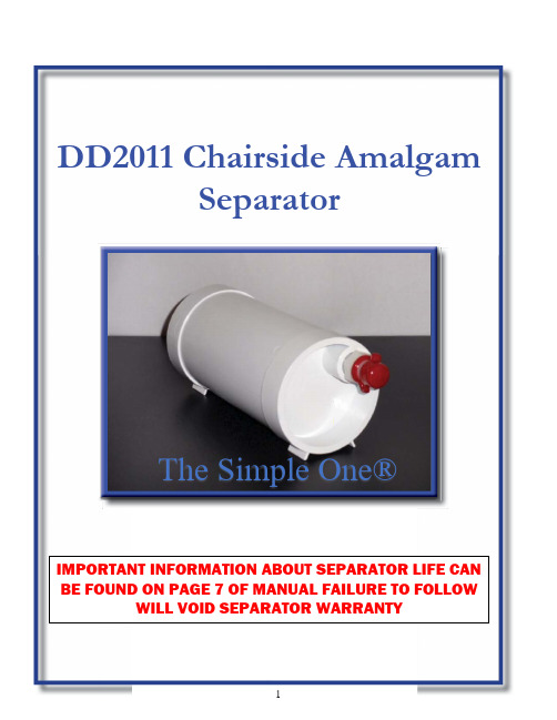
DD2011 Chairside AmalgamSeparatorThe Simple One® IMPORTANT INFORMATION ABOUT SEPARATOR LIFE CAN BE FOUND ON PAGE 7 OF MANUAL FAILURE TO FOLLOW WILL VOID SEPARATOR WARRANTYProduct Description andSpecificationsThe DD2011 disposable chairside amalgam sepa-ration system has been tested and passed the ISO 11143 protocol [ISO 1143:2008(E)]. The DD2011 is designated as a Type 3 amalgam separator .The maximum water flow rate is 1.0 liters per minute. The maximum fillable volume of the separator is calculated to be 360 ml. The sepa-rator is installed in the dental vacuum line (HVE line). A loss of suction will occur 3-7 days prior to the DD2011 becoming full and requiringreplacement. The DD2011 needs to be changed when the air flow at the HVE tip is no longer ade-quate, which will be demonstrated by the noticea-ble decrease of suction. The decrease in suction is the gauge used to determine the necessary replace-ment of the unit. If the system is not replaced within 3-7 days after noticeable decrease of suc-tion is noted and is allowed to fill completely, the unique design of the system will alarm you by shutting off completely, not allowing hazardous waste to flow past the unit.The change out rate varies from 9 to 12 months and depends upon chair activity. The 2011 is de-signed to handle a Standard dental vacuum of 7 inches of Hg. Instructions for changing of the amal-gam separator are found at the end of the manual.InstallationInstallation of the chairside amalgam separator varies as a function of dental chair design. Photo-graphs of typical installations are shown below and may be a useful guide. The separator is placed under the dental chair and spliced in line with the high volume evacuation lines. The unit ships with 1/2, 5/8, and 1 inch nylon hose barb fittings. The separator has two NPT ports: one is the “inlet”port and is located “off axis”. The second port is the discharge and is located in the center axis of the separator. It is important to have the “inlet”port connected to the HVE tip (i.e. coming from the patient) and the “outlet” Port connected to the vacuum source ( dental vacuum pump) In manyd ental chairs, the vacuum hose is “snaked” inside the chair and subject to sharp bends which limit the air flow through the hose. A short direct con-nection from tthe floor to the separator improves air flow and prevents debris and prevents debris from clogging the lines.It is recommended that the chairside trap remain in use. The trap prevents large pieces of debris from clogging the lines.The Department of Defense Medical Military Fa-cilities Design and Construction Criteria (Mili-tary Handbook-1191) calls for the following den-tal vacuum system operating criteria to be met:21 to 27 kPa (6 to 8 in-Hg) with a minimum vacuum of 21 kPa (6 in-Hg) to be maintained at the farthest HVE inletA flow rate of 3.3 liters/second (7 standard cubic feet per minute).Amalgam Waste Recycling Issues Contact your local environmental specialist prior to disposal of any mercury containinghazardous wasteAlthough mercury in the form of dental amalgam is very stable, amalgam should not be disposed of in the garbage, infectious waste “red bag,” or sharps container. Mercury containing amalgam waste generated in the dental operatory can on occasion meet the requirement of a hazardous waste. Amalgam should not be rinsed down the drain. Some communities incinerate municipal garbage, medical waste, and sludge from wastewater treatment plants. If amalgam waste ends up being incinerated mercury vapor can be released to the environment due to the high tem-peratures used in the incineration process. In-creasingly, local communities are enacting re-strictions on the incineration of wastes contain-ing mercury.The DD2011 amalgam separator shown installed on a Dental EZ chair. The unit is placed on the floor next to the chair. It can be located inside the floor mounted junction box if space permits. The unit shown here is placed to the side of the chair but can be move to any location that is convenient. The unit shown here has the 5/8 inch nylon hose barb fittings with the red vinyl caps. For some in-stallations, the HVE hose may have to be relo-cated outside the chair. Velcro® fasteners can be used to mount the unit to the dental chair, keeping the unit off the floor.The photograph at the left shows the inflow side of the DD2011. Note that the inflow port is “off axis”. This side of the separator is connected to the HVE line coming from the patient. Note the red vinyl cover over the 5/8 inch inflow port of the separator. When the separator is loaded with de-bris and needs changing, the red vinyl cover is placed over the port to prevent any leakage of de-bris from the separator.The photograph at the left shows the outflow side of the DD2011. Note that the outflow port is in line with the long axis of the separator. This side of the separator is connected to the vacuum source. Note the red vinyl cover over the 5/8 inch outflow port of the separator. When the separator is loaded with debris and needs changing, the red vinyl cover is placed over the port to prevent any leakage of debris from the separator.Recycling ProgramThe American Dental Association Best Management Practices (BMPs) recommends that all amalgam waste be recycled.Vacuum Line Cleaner Effects on Hg Lev-els in Dental Wastewater Vacuum line cleaners are recommended by some manufacturers of dental vacuum systems to help keep the lines from clogging and to limit the for-mation of odors. The chemical makeup of line clean-ers can have important effects on dissolved Hg levels in dental wastewater. Oxidizing line cleaners, espe-cially chlorine containing products like sodium hy-pochlorite (bleach) can mobilize or dissolve Hg con-tained in amalgam particles found in vacuum lines.Oxidizing vacuum line cleaners should be avoided. Vacuum Line Cleaners and Foam Pro-ductionMany different issues can affect the performance and endurance of dry dental vacuum systems. The use of vacuum line cleaners can have a profound effect on both dry vacuum pumps and on DD2011 amalgam separator. Foam producing line cleaners produce plaque-like deposits in vacuum lines and more sig-nificantly have been shown to damage dental vac-uum pumps. Foam enters the dry vacuum pumps and over time cause the buildup of deposits that causes them to fail prematurely. Foam also causes the DD2011 amalgam separator to clog prematurely.For these reasons, the use of line cleaners that foam is not recommended. We recommend the use of PureVac (Sultan Chemists, Englewood, N.J.) as it does not mobilize Hg (to a significant extent) and does not foam to the point where it will damage vacuum pumps.Air Flow Levels (Vacuum Quality) inDental UnitsThe ability of the High Volume Evacuator (HVE) to remove water and d ebris from the dental patient’s mouth is an important issue. Adequate suction levels are needed to safely remove water and debris from the patient’s oral cavity. A critical factor in HVE vac-uum level is the diameter and geometry of the vac-uum lines that run through the dental chair. Small di-ameter lines running a tortuous course can limit air flow and cause inadequate vacuum Right angle (90 degree) vacuum line fittings and “pinched” vacuum lines can substantially reduce air flow leading to in-adequate HVE performance. For this reason, it is rec-ommended that vacuum levels at the HVE tip be as-sessed prior to installation of the DD2011 amalgam separator. In some cases, rerouting the vacuum lines outside the chair may be needed to achieve adequate vacuum levels (before the DD2011 is installed). We recommend the use of the Dental EZ Flowcheck™ vacuum gauge to measure chairside vacuum levels before and after installation of the filtration unit. The Flowcheck™ dental vacuum flow measurement de-vice is available from Dental EZ Corporation. /ramvac/accesso-ries/flowcheck.htmlThere is a draft ISO standard for dental vacuum sys-tems, ISO/PDTS 22595-1. The draft ISO standard calls for an air flow of at least 250 liters/minute (4.1 liters/second) at the HVE tip. Testing of the DD2011 chairside amalgam separator has demonstrated mini-mal impact on suction quality (0.1 inches of Hg)AddendumPrior to the installation of the DD2011 amalgam sep-arator:1.Verify that the dental chair has an adequate vacuum level. Vacuum levels can be measured with a digital vacuum gauge at the HVE tip. A recom-mended vacuum gauge is the DentalEZ Flowcheck™. More information at: http://www. /ramvac/accessories/flowcheck.html2.A n alternative to the Flowcheck™ is the DentalEZ Vacheck™ which is a Pass/Fail device that fi ts into the HVE tip. Adequate vacuum will hold the device in the HVE when it is turned “upside down” More information on the Vacheck™ is avail-able at: /ramvac/ accesso-ries/vacheck.html3.Before taking vacuum measurements: in-stall a new or “clean” chairside trap in dental chair. There may be several causes for inadequate vacuum levels:a. 90 degree fittings on dental vacuumlines can severely impact air flowb. kinked vacuum hosesc. vacuum hoses plugged with debris4.To improve air flow, vacuum lines can be re-routed outside the dental unit to improve dental vac-uum levels5.Once the vacuum levels have been verified as providing adequate air flow, the DD2011 can be installed. Vacuum levels should be re-measured and recorded in a log book after the installation of the DD2011.e an appropriate vacuum line cleaner to help maintain dental vacuum lines. We recommend the use of Purevac (Sultan Healthcare, Englewood, N.J.). Purevac is a non-foaming line cleaner that does not substantially mobilize mercury from amal-gam.Always wear personal protective equipment when changing or replacing the DD2011 Amalgam Sepa-rator. At a minimum the person changing the separa-tor should wear gloves, protective eye wear, mask and gown. Any remaining fluid in the separator should be considered potentially infectious medical waste.The Chairside amalgam separator will need to be changed when vacuum levels fall below recom-mended values (see the manual for additional de-tails). The used amalgam separator ( still connected to the vacuum lines) should be placed in a tray that will collect any spilled wastewater, preventing it from contacting the Operating floor. The inflow side of the amalgam separator is an-gled up at approximately 45 degrees and the vac-uum hose is pulled off the inflow side off the inflow side barb. The end of the vacuum lines should be kept in the tray to trap any wastewater that may re-main in the lines. Any wastewater that collects in the tray should be dis-posed of appropriately. DO NOT pour any of the wastewater down the drain as it may contain substantial amounts of mercury. The red vinyl cap is then placed over the inflow hose barb which seals this side of the amal-gam separator. The amal-gam separator is then an-gled at 45 degrees so that the outflow barb is pointed up and the pro-cess is repeated. The red vinyl cap securely placed on the outflow barb. Photograph showing the used amalgam separator disconnected from the vacuum lines. The red caps are securely placed on both ends and used amalgam separator is ready for recycling. A new DD2011 amalgam separa-tor can now be installed by placing the vacuum hoses on the appropriate hosebarb fittingsHOW TO AVOID PREMATURE AMALGAM SEPARATOR LIFE1 ) Never use on a hygienist chair. Cleaning compounds will clog amalgam separator with prophy paste, etc. Hygienist chairs have no hazardous materials and can go directly to sewer system.2) Do not use a foam producing line cleaner. Plaque-like deposits will build up and have been shown to damage dental vacuum pumps.3) We highly recommend a non-foaming liquid cleaner. Some granular and tablet cleaners do not break downand can cause premature amalgam separator life. 1 Liter maximum or manufacturers recommendation.4) It is very important not to use 90° fitting when installing amalgam separator. It will cause improper vacuum flow.5) Do not use granular or tablet cleaners in amalgam trap it will cause premature amalgam separator failure.It is very important not to use 90° fitting when installing filter. It will cause improper vacuumflowDD2011 CHAIRSIDE AMALGAM SEPARATOR1. Verify suction lines have adequate vacuum prior to installation.2. Clean suction lines with line cleaner. Turn off vacuum pump before proceeding with the installation.3.Thread the included hose adapters into each inlet and outlet of separator housing. Teflon tape on threads isrecommended. Attach flexible plastic cap plugs for recycling convenience. 4. Cut the main suction line at a proper location for the separator.5. Connect the suction hose portion from the chair to the off-center (inlet) port of separator.6. Connect central (outlet) port of separator to the remaining suction hose leading to the junction box .7. Avoid sharp bends and elbows in the suction hoses which decrease line vacuum.8. Turn on the vacuum pump to verify suction with separator installed.IMPORTANT• Hygiene procedures using polishing powders/prophy pastes clog the separator and must be avoided in opera-tories with the DD2011 separator installed.• Use non-foaming, neutral pH (6-8) liquid line cleaners to maintain service life of the separator and reduce dissolved mercury. 1 liter maximum or manufacturers recommendation. • Avoid sharp bends and elbows in the suction hoses which decrease line vacuum.REFER TO INSTRUCTION MANUAL PAGE 2 FOR MORE DETAILSINSTALLATION SUMMARYFROM CHAIR (INLET)TO VACUUMPUMP ( O UTLET )TO VACUUM PUMPJUNCTION BOXHose AdapterDENTALCHAIRDD2011。
泥浆分离器工作原理

泥浆分离器工作原理
泥浆分离器是一种设备,其工作原理是利用离心力将泥浆中的固体颗粒和液体分离。
当泥浆进入分离器后,首先经过一个进料管道进入到分离器的圆柱体内部。
在圆柱体内部,泥浆由于离心力的作用被分离成固体相和液体相。
固体相(即固体颗粒)被离心力推向圆柱体的内壁,并在内壁上形成一个固体相层。
这时,固体相的质量会迅速增加,从而增加固体相层的厚度。
固体相随后沿着内壁移动,最终进入到圆柱体的下部,形成一个固体相底层。
液体相(即液态泥浆)则受到离心力的作用向外被挤压,形成一个环状的液体相层。
液体相的质量相对固体相来说较小,因此液体相层的厚度较薄。
分离后,固体相和液体相通过不同的出料管道分别排出。
固体相通过固体出料口排出,一般通过开启阀门的方式控制排出速度。
液体相则通过液体出料口排出。
泥浆分离器常用于石油、化工、污水处理等领域,用于分离泥浆中的固体颗粒,从而达到净化和回收液体的目的。
GIW LSA S泥浆传输泵说明书

8 Impeller release ring for easy impeller removal. Feature is standard on larger pump sizes.
900 PSI test availablal end suction. Single wall pump shell with replaceable suction side liner, three (for larger particle solids) or four vane impeller options.
Interchangeability
To optimize wear life and efficiency, various hydraulic design and material options can be used on the same mechanical end.
2 Two aramid gaskets aid in the removal of the impeller.
3 Replaceable suction liner facilitates pump internal inspection and minimizes wear part usage cost. Liner can be rotated at intervals to increase wear life.
Slurry pipeline
Tailings discharge
LSA10-2008
GIW Model LSA S Pumps
Low Maintenance, Severe Duty, Abrasion Resistant
浓稠化分离器说明书

Cyclonic desanding of fluids is a robust method of removing problem solids from your production system prior to the main production separators without the risk of rapid blockage, manual intervention, and operational expense associated with filters. It is particularly suitable for short bursts of high concentration solids flow or control of erosive solids over the longer term. The cyclonic action separates the solids into the accumulation vessel - this lower section can be isolated allowing the solids to be discharged without interrupting the process flow. 10k Wellhead Cyclonic Desanders are just one part of the NOV sand control equipment portfolio. Whether it is well clean-up or solids breakthrough during production, NOV can advise on the most cost-effective solution./wellstreamprocessing ****************************Design, material, classAPI 6A, ASME VIII div. 2, EE-360 Rated pressure,temperature10k psi, -29°C to 177°C (-20°F to 350°F)FrameDNV 2.7-3, 2.4 m x 2.8 m x 6.1 m Weight19,320 kg (dry)Capacity15,000 bpd. 100 MMSCFD Accumulation 0.4 m3Design specificationsWellhead cyclonics 10k MultiPhase DesanderProtect your downstream equipment from erosionBenefits:• Robust, high-capacity unit• Erosion resistant replaceable liners to maximize vessel life• Multiple liner sizes available to maximize performance• Enhanced corrosion protection• Standard product designs available to minimize cost• Custom designs available to meet project needs• NOV expertise in solids handling© 2021 NOV Inc. All rights reserved. JIRA 14574。
气液分离器操作规程

生产分离器操作规程1。
1启动前的准备工作1。
1。
1检查气液分离器闸门是否灵活可靠,液位计、安全阀、压力表是否完好。
1。
1。
2冬季使用时,应打开热水循环进出口闸门检查气液分离器采暖盘管是否完好,夏季使用时,关闭热水循环进出口闸门。
1。
1。
3检查排污管线是否畅通1。
2气液分离器的启用1。
2。
1打开分离器进气闸门,当压力达到0.1Mpa 时,打开出气闸门,并调节出气闸门,给锅炉供气,检查供气管线是否有泄露。
1。
2。
2调节放空闸门,使分离器压力稳定在0.15Ma.1.2。
3当分离器内液位达到0。
1m时,打开排污阀,向污油箱排放液体。
1。
3正常运行时的检查1.3。
1检查分离器的压力是否正常;1。
3。
2检查供气管线及放空管线是否有泄露.1.4安全阀拆卸与安装1.4。
1分离器安全阀每年效验一次,由区统一送到指定地点效验。
1。
4。
2效验安全阀前需要备用一个同类型,已效验好的安全阀.1.4。
3拆卸安全阀时,关闭分离器进口闸门、供气(用户)闸门,放空分离器压力,拆卸后安装备用安全阀。
常压锅炉(水套式加热炉)操作规程5.1点火前的检查与准备5.1。
1检查循环泵、补水泵是否完好,手动盘车是否灵活,电气开关及接线、接地是否可靠.5.1.2检查整个循环系统是否密闭,有无滴漏窜水现象,阀门、旋塞是否灵活可靠。
5.1。
3检查烟道挡板是否已经打开,炉顶排气管是否畅通。
5。
1.4检查烟气管线(燃气炉)是否畅通,管线及控制阀有无漏气、窜气现象,炉前燃气压力是否满足(一般点火前燃气压力应在0。
03MPa—0。
15MPa);燃煤(燃煤炉)是否准备充分。
上述检查合格(一切不安全因素消除完毕),各项准备工作完成,方可进行点炉。
5。
2点火与运行5。
2。
1启动循环水泵,使锅炉及管网内的水先循环流动起来。
5。
2。
2点火。
点火前就应全开燃烧器风门或炉门、灰门,使炉内自然通风5-10分钟。
5.2。
2。
1若以天然气作燃料,应先在炉外点燃点火棒,将点火棒从点火孔伸入火嘴前方,然后缓慢开启天然气阀门。
泛泥洁盒 STV 高性能泥浆吸收器说明书

supports ensure excellent flow distribution, thus fully utilising the surface area of the desiccant and avoiding dead spaces.
Various types of desiccant adsorption material are available for the removal of different types of contamination from gas streams. All adsorbers are equipped with flanged connections as standard, if necessary screw connections can be provided. All external surfaces are protected with an anti-corrosion resin coating.
TGA112/16C-B/A TGA112/16C-B/A TGA112/16C-B/A TGA112/16C-B/A TGA116/16C-B/A TGA116/16C-B/A TGA116/16C-B/A TGA118/16C-B/A TGS214/16C-F/A TGS216/16C-F/A TGS216/16C-F/A TGS216/16C-F/A TGS218/16C-F/A TGS218/16C-F/A TGS218/16C-F/A TGS218/16C-F/A TGS222/16C-F/A
Series STV
Wedges wire desiccant suppor t
Adsorption cycle Regeneration cycle, heating phase
