800系列BRANSON超声波说明书
DXI800 中文手册

2005 Beckman Coulter, Inc. P/N 986266E 3/05
i
UniCel DxI 800 使用说明
目录
4 样品架和样品容器 . . . . . . . . . . . . . . . . . . . . . . . . . . . . . . . . . . . . . . . . . . .4-1
本手册与 UniCel DxI Access 免疫分析系统 一同使用。
Access、 AccuTnI、 DxI、 Hybritech、 Ostase、 UniCel 以及 BECKMAN COULTER 徽标是 Beckman Coulter, Inc. 的商标
UniCel DxI 800 使用说明
2 关闭和重新启动 . . . . . . . . . . . . . . . . . . . . . . . . . . . . . . . . . . . . . . . . . . . . .2-1
超声波热量计说明书
目录一概述 .............................................................................................................................................. - 3 - §1.1 引言 .................................................................................................................................... - 3 - §1.2 FC-80的特点 ....................................................................................................................... - 3 - §1.3 工作原理............................................................................................................................. - 3 - §1.6 可选备件............................................................................................................................. - 4 - §1.7产品型号编码规则 ............................................................................................................... - 4 - §1.8 外形图和接线图.................................................................................................................. - 5 - §1.9 性能指标............................................................................................................................. - 6 - 二开始安装测量................................................................................................................................ - 7 - §2.1 开箱检查............................................................................................................................. - 7 - §2.2 供电电源............................................................................................................................. - 7 - §2.2.1便携式 ....................................................................................................................... - 7 - §2.2.2固定式 ....................................................................................................................... - 7 - §2.2.3接线........................................................................................................................... - 7 - §2.3 通电 .................................................................................................................................... - 7 - §2.4 键盘 .................................................................................................................................... - 8 - §2.5 怎样操作............................................................................................................................. - 8 - §2.6 窗口简介............................................................................................................................. - 9 - §2.7 快速输入管道参数和步骤 ................................................................................................... - 9 - §2.8 选择测量点 ....................................................................................................................... - 10 - §2.9 探头接线........................................................................................................................... - 10 - §2.10 安装探头......................................................................................................................... - 10 - §2.10.1 探头安装距离........................................................................................................ - 11 - §2.10.2 探头安装方式........................................................................................................ - 11 - §2.10.3 V法 ....................................................................................................................... - 11 - §2.10.4 Z法........................................................................................................................ - 11 - §2.10.5 N法(不常用的方法) .......................................................................................... - 11 - §2.10.6 W法(极不常用的方法)...................................................................................... - 12 - §2.10.7 插入式传感器的安装............................................................................................. - 12 - §2.11 检查安装 ......................................................................................................................... - 15 - §2.11.1 信号强度 ............................................................................................................... - 15 - §2.11.2信号质量(Q值) ...................................................................................................... - 15 - §2.11.3 总传输时间、时差................................................................................................. - 16 - §2.11.4 传输时间比............................................................................................................ - 16 - §2.11.4 安装时注意的问题................................................................................................. - 16 - 三怎样使用..................................................................................................................................... - 17 -§3.1 怎样判断流量计是否工作正常 .......................................................................................... - 17 -§3.2 怎样选择流量单位制......................................................................................................... - 17 -§3.3 怎样选择瞬时流量单位..................................................................................................... - 17 -§3.4 怎样选择累积流量单位..................................................................................................... - 17 -§3.5 怎样选择累积器倍乘因子 ................................................................................................. - 17 -§3.6 怎样打开或关闭流量累积器.............................................................................................. - 17 -§3.7 怎样实现流量累积器清零 ................................................................................................. - 17 -§3.8 怎样恢复出厂设置 ............................................................................................................ - 17 -§3.9 怎样使用阻尼器稳定流量显示 .......................................................................................... - 17 -§3.10 怎样使用零点切除避免无效累积..................................................................................... - 18 -§3.11 设置零点提高测量精度 ................................................................................................... - 18 -§3.12 修改仪表系数(标尺因子)进行标定校正...................................................................... - 18 -§3.13 密码保护(加锁与开锁)................................................................................................ - 18 -§3.14 使用键盘锁定,避免无关人员操作................................................................................. - 18 -§3.15 怎样使用打印机.............................................................................................................. - 19 -§3.16 怎样使用4~20mA电流环输出........................................................................................ - 19 -§3.17 怎样输出模拟电压信号................................................................................................... - 19 -§3.18 怎样使用频率信号输出................................................................................................... - 19 -§3.19 怎样输出累积脉冲 .......................................................................................................... - 20 -§3.20 怎样产生输出报警信号................................................................................................... - 20 -§3.21 怎样使用蜂鸣器.............................................................................................................. - 20 -§3.22 怎样使用OCT输出 ........................................................................................................ - 21 -§3.23 怎样使用继电器输出....................................................................................................... - 21 -§3.24 怎样修改日期时间 .......................................................................................................... - 21 -§3.25 怎样调整LCD显示器..................................................................................................... - 21 -§3.26 怎样使用RS232/RS485串行口 ....................................................................................... - 21 -§3.27 怎样查看每日、每月、每年流量 .................................................................................... - 21 -§3.28 怎样连接压力信号和温度信号(模拟输入) .................................................................. - 21 -§3.29 怎样实现断电时间段内流量的自动补加 ......................................................................... - 22 -§3.30 怎样使用工作计时器....................................................................................................... - 22 -§3.31 怎样使用手动累积器....................................................................................................... - 22 -§3.32 怎样使用批量(定量)控制器........................................................................................ - 22 -§3.33 怎样对模拟输出进行校准 ............................................................................................... - 22 -§3.34 查看电子序列号和其他细节............................................................................................ - 22 -四命令/显示窗口详解..................................................................................................................... - 23 -§4.1 显示窗口一览表................................................................................................................ - 23 -§4.2 显示窗口顺序介绍............................................................................................................ - 24 -五问题处理..................................................................................................................................... - 41 -表1. 硬件上电自检信息及原因对策......................................................................................... - 41 -表2. 工作时错误代码原因及对策............................................................................................. - 42 -其他常见问题问答 .................................................................................................................... - 42 -六联网使用及通信协议 .................................................................................................................. - 44 -§6.1 概述.................................................................................................................................. - 44 -§6.2 流量计串行口定义............................................................................................................ - 44 -§6.3 同上位机的RS232直接联接............................................................................................. - 44 -§6.4 通信协议及其使用............................................................................................................ - 44 -§6.4.1 基本命令................................................................................................................. - 44 -§6.4.2 功能前缀和功能符号 .............................................................................................. - 46 -§6.4.3 兼容协议1.............................................................................................................. - 46 -§6.4.4 兼容协议2.............................................................................................................. - 47 -§6.5 键值编码........................................................................................................................... - 49 -§6.7 编程举例........................................................................................................................... - 49 -§7.1 功能介绍........................................................................................................................... - 50 -§7.2热量测量硬件接线............................................................................................................. - 50 -§7.3怎样进行热量测量............................................................................................................. - 50 -§7.4温度、压力等信号的量程范围设置 ................................................................................... - 51 -§7.5模拟输入的校准................................................................................................................. - 51 -§7.5联网时模拟输入量的读取.................................................................................................. - 51 -§8.1 质量保证........................................................................................................................... - 52 -§8.2 公司服务........................................................................................................................... - 52 -§8.3 产品升级........................................................................................................................... - 52 -§8.4 技术咨询........................................................................................................................... - 52 -九附录............................................................................................................................................ - 53 -§9.1常用液体声速和粘度 ......................................................................................................... - 53 -§9.2常用材料声速............................................................................................................................... - 53 -一概述§1.1 引言欢迎您选择使用性能更优异、功能更多、采用了专利技术制造的FC-80系列超声波流量计。
Branson超声波手册中文

Branson+超声波手册-中文目录质保1安全预防3简介3 超声清洗机4 拆封清洗机4 安装清洗机5 设备规格6 清洗机如何工作7 操作清洗机7 操作MT和MTH型清洗机10 操作DTH型清洗机14 排空清洗机16 优化清洗机18 使用提示19 清洗方式21 清洗液24 故障排除28 服务中心安全预防在使用超声清洗机之前,请完整阅读和理解这些安全预防的规则。
不遵循这些规则将导致对人身的伤害和财产的损失。
避免电击一定要拔下电源插头●在加满或清空水箱之前,●一定要保持控制面板以及周围区域的洁净和干燥-及时清除溢出到水箱边缘的水。
水和高压可能导致电击。
●在没有正确接地之前,请不要操作清洗机●不要移除接地线和插头●不要打开清洗机-清洗机内的高压非常危险●不要将清洗机浸入水中防止个人伤害和财产损失●使用清洗机时要采用有排出口的护盖或者不使用护盖●使用以水为主的清洗液●一定不要使用酒精、汽油或者其它可燃性清洗液。
否则将导致火灾、爆炸,并且使保修失效。
一定使用以水为主的清洗液。
●不要使用可能损坏水箱的酸性物质。
●不要碰触不锈钢水箱-其温度可能很高 ●不要使液体温度超过70℃。
●当清洗机运转时,不要将手伸入水箱。
否则会导致不舒适或皮肤刺激。
避免接触并保持合适的通风。
●不要采用含有氯气漂白的清洗液防止清洗机的损坏●定期更换清洗液 ●不要覆盖盖子上的出口 ●不要在无水情况下操作清洗机●不要将部件或容器直接放在清洗水箱的底部,采用托盘或绳索悬置清洗物。
否则将损坏传感器并导致保修失效。
在加热或超声打开时,不要让溶液下降到操作线下3/8英寸以下。
否则将导致传感器或加热器损坏并导致保修失效。
介 绍超声清洗机该系列的超声清洗机包括5个型号,包括1/2加仑,3/4加仑,1-1/2加仑,2-1/2加仑和5-1/2加仑。
每个型号都装备有耐用的工业用40KHz 传感器。
强大的清洗能力加上内置的清洗频率能够提供有效的统一的清洗。
1/2和3/4加仑型号装有一个浇铸的有倾斜角度的边缘,使从水箱中清空溶液非常简便。
Branson+超声波手册-中文
1安全预防
3简介
3超声清洗机
4拆封清洗机
4安装清洗机
5设备规格
6清洗机如何工作
7操作清洗机
7操作MT和MTH型清洗机
10操作DTH型清洗机
14排空清洗机
16优化清洗机
18使用提示
19清洗方式
21清洗液
24故障排除
28服务中心
安全预防
在使用超声清洗机之前,请完整阅读和理解这些安全预防的规则。不遵循这些规则将导致对人身的伤害和财产的损失。
当你第一次向清洗机内注水或者重新添加新溶液时,要使用温水。先打开加热器(按HEAT开关),然后打开超声(按SONIC或者旋转计时器),盖上盖子,溶液将很块加热到所需温度。
清洗机附件
备件包括常规的和可固定烧杯的盖子,实心的带孔的盘子,网兜和烧杯。
拆封清洗机
请仔细检查你的清洗机和纸板箱是否有内部或外部损坏。如果你发现有破损,请在通知我们的销售商之前立即联系运输商。请保留商品包装以备将来之用。
在加热或超声打开时,不要让溶液下降到操作线下3/8英寸以下。
一定不要使用酒精、汽油或者其它可燃性清洗液。否则将导致火灾、爆炸,要使用水基溶液。
不要使用酸性物质,这可能损坏水箱。
不遵守这些注意事项将导致保修失效
步骤
做法
1
选择清洗液(参考第23页溶液对于金属的作用)
2
考虑你需要清洗的物品以及所需的溶液量,向水箱内添加温的自来水直到操作线(离顶端1英寸)
3
添加清洗液
4
插入接地插座
5
为达到最大功效,请参考第16页,“优化你的清洗机”
注意
如果你是第一次使用清洗机,或者你更换了清洗液,你必须先除去溶液内气体。如果不是,请跳到“清洗物品”一节。
超声波说明书

超声波使用说明书模块实物图如下图所示:123(12V+)(GND)(485通信口)一、接线说明模块采用DC12V供电;图中标号为1的红色箭头处接电源正,标号为2的红色箭头处接电源负。
标号为3的红色箭头处接485通信线。
二、通信协议说明模块采用485通信,波特率为9600;通信协议如下:协议头预留字节预留字节预留字节距离高字节距离低字节帧尾校验和0Xfe0X000X000X000Xxx0Xxx0Xef0Xxx校验和计算方法:从协议头到帧尾个各数据之和取最低两位距离返回值单位为:mm;例:0xfe0x000x000x000x040xb00xef0xa1当返回数据如上所示时,测距结果为1200mm。
三、模块测量方法由于模块是高精度设计用,所以对测量环境有严格的说明界定。
请参考如下测量安装方式,否则会产生较大的测量误差。
安装方式如下:滤波处理装置,可以用PCB板来固定代替移动平面是本模块的移动方向,反射平面是基础高度。
在移动平面方向前后运动将会测量到实际的反射平面与模块的实际距离。
测量条件:1:参考平面(模块固定的平面)一定要垂直于反射平面。
2:测量模块在反射面这个方向上的1米半径范围内不能有遮挡物。
3:在移动模块到了指定位置后(想测量的距离位置处),模块的前端一定要绝对垂直于反射面。
4:根据超声波的扇形反射面原理,最好在超声波的接收端安装反射能量限定装置,这样能更准确的获得实际的测量结果。
在实际应用场合,有更多的安装要求。
基本的测量测试,照目前条件能基本反应出来。
成都镓舒适科技有限公司2014-09-01。
Branson+超声波手册-中文
目录质保1安全预防3简介3 超声清洗机4 拆封清洗机4 安装清洗机5 设备规格6 清洗机如何工作7 操作清洗机7 操作MT和MTH型清洗机10 操作DTH型清洗机14 排空清洗机16 优化清洗机18 使用提示19 清洗方式21 清洗液24 故障排除28 服务中心安全预防在使用超声清洗机之前,请完整阅读和理解这些安全预防的规则。
不遵循这些规则将导致对人身的伤害和财产的损失。
避免电击●在加满或清空水箱之前,一定要拔下电源插头●一定要保持控制面板以及周围区域的洁净和干燥-及时清除溢出到水箱边缘的水。
水和高压可能导致电击。
●在没有正确接地之前,请不要操作清洗机●不要移除接地线和插头●不要打开清洗机-清洗机内的高压非常危险●不要将清洗机浸入水中防止个人伤害和财产损失●使用清洗机时要采用有排出口的护盖或者不使用护盖●使用以水为主的清洗液●一定不要使用酒精、汽油或者其它可燃性清洗液。
否则将导致火灾、爆炸,并且使保修失效。
一定使用以水为主的清洗液。
●不要使用可能损坏水箱的酸性物质。
●不要碰触不锈钢水箱-其温度可能很高●不要使液体温度超过70℃。
●当清洗机运转时,不要将手伸入水箱。
否则会导致不舒适或皮肤刺激。
避免接触并保持合适的通风。
●不要采用含有氯气漂白的清洗液防止清洗机的损坏●定期更换清洗液●不要覆盖盖子上的出口●不要在无水情况下操作清洗机●不要将部件或容器直接放在清洗水箱的底部,采用托盘或绳索悬置清洗物。
否则将损坏传感器并导致保修失效。
●在加热或超声打开时,不要让溶液下降到操作线下3/8英寸以下。
否则将导致传感器或加热器损坏并导致保修失效。
介绍超声清洗机该系列的超声清洗机包括5个型号,包括1/2加仑,3/4加仑,1-1/2加仑,2-1/2加仑和5-1/2加仑。
每个型号都装备有耐用的工业用40KHz传感器。
强大的清洗能力加上内置的清洗频率能够提供有效的统一的清洗。
1/2和3/4加仑型号装有一个浇铸的有倾斜角度的边缘,使从水箱中清空溶液非常简便。
Branson超声轮胎切割系统介绍

33 COMPANY CONFIDENTIAL
34 COMPANY CONFIDENTIAL
轮胎切割刀与橫向振動
当轮胎切割刀的宽度大 于半波长,橫向振动就 会出现。 (只适用于20kHz焊接 頭)
在适当的位置加上長孔 ,减少橫向振动。
35 COMPANY CONFIDENTIAL
40kHz换能器的振动幅度 为 10microns
23 COMPANY CONFIDENTIAL
換能器
24 COMPANY CONFIDENTIAL
换能器的保养
无橫向振动的工作环境
减少热力的产生
减少撞击 产生超声时,非夹持区域点严禁接触金属
换能器仅起辅助夹持作用,严禁使用过大夹紧力
建议使用空气过滤装置,定期清洁和更换
工作环境温度在5-50℃之间 发生器避免离地太近,防止灰尘进入 保证进、排气口顺通 发生器远离射线或热通风口 定期清洁必要部件(视具体情况)
19 COMPANY CONFIDENTIAL
换能器的振动原理
电流经过换能器,在换能器 內产生电磁场
轮胎超声切割的原理
由换能器—调幅器—切割刀组成的共振体,产生共 振,对轮胎橡胶热作用的结果.
共振的基本条件
__共振体的频率相同 __共振体的长度为半波长的整数倍
3 COMPANY CONFIDENTIAL
超声橡胶切割系统
功率发生器
• 工頻电流转换为高頻电流, •
切割过程控制中心. 高頻电流能转换为机械振 动能. 改变振幅及作为夹持点的 作用. 热作用切割橡胶.
Branson Bransonic 超声清洗浴缸说明书

The Branson reputation for impeccable quality and reliable ultrasonics is unsurpassed. Our global network of distributors ensures that you will have the machinery, accessories, supplies, and support you need to meet your basic cleaning needs for the most demanding applications.Bransonic CPX Series•S leep mode provides energy savings automatically by shutting off unit if controlThe CPX SeriesThe value leader for quality and reliability.The Bransonic M Series includes two simple-to-use models: the M and MH Series. Both series are designed for basic yet effective cleaning, with set-it-and-forget-it mechanical timers, which can be set up to 60 minutes or run continuously. MH Series units also offer a heating option. And both series are excellent for use in a variety of applications:aboratories and dental offices ewelry and precious metalsBransonic M SeriesTo conserve energy, the unit goes into sleep mode if control keys are not touched for 15 minutes after cycle ends, and restarts after any key is touched.Temperature can be set for either Fahrenheit or Celsius CPX Series is completely programmable, so engineers can choose temperature, start, and stop times for “set-it-and-forget-it” operation.Degassing periods of up to 99 minutes also allow for various sample prep applications.Digital timer allows for continuous ultrasonic operation or can be set for up to 99 minutes.Ultrasonic power tracking maintains steady,consistent activity in the bath when conditions change.High/low power control provides safer cleaning of delicate components. 100% power for normal, or 70% for delicate applications.Precision Cleaning for All Types of ApplicationsAccessories and SolutionsLaboratoryThoroughly removes blood, protein, andcontaminants on tools such as glassware, lenses, instruments, and precision components.Medical and Dental LabsOffers a safer, more consistent way to clean dental and medical instruments in combination with sterilization.IndustryDeep cleans to remove dirt, grease, waves, and oils from industrial parts and components of all kinds, including steel, light and nonferrous metals, plastic, and glass.ElectronicsCompletely removes flux and contaminants from such precision components as PC boards, SMDs, quartz crystals, capacitors, and many others.JewelryThoroughly cleans and restores brilliance towatches, chains and charms, settings, coins, fine jewelry, and clockworks.OpticalEnsures precision cleaning of optics.Bransonic baths are in use worldwide, providing simple, effective results for the ultimate in ultrasonic cleaning.Beyond CleaningBranson ultrasonic cleaners also can be used for sample preparation; degassing liquids, mixing and homogenization, dissolving solids, lysing and dispersion of particles.AccessoriesBransonic ® ultrasonic baths also can be accessorized to best suit your specific cleaning or laboratoryneeds. Choose the appropriate suspension method for your applications, solid or perforated tray, basket, support rack, and beaker holder to customize each unit as needed.The Right Cleaning SolutionIt’s the most important decision you can make. A large variety of excellent formulations are available, designed for specific applications. Proper selection is crucial for acceptable cleaning activity and to preclude undesirable reactivity with the items being cleaned.M Series MH Series CPX Series CPXH Series 60-minute 60-minute 99-minute 99-minute。
超声波测速仪用户手册说明书
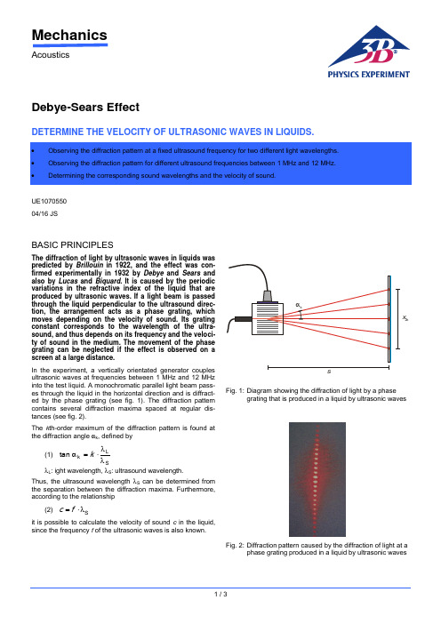
MechanicsAcousticsDebye-Sears EffectDETERMINE THE VELOCITY OF ULTRASONIC WAVES IN LIQUIDS.UE1070550 04/16 JSBASIC PRINCIPLESThe diffraction of light by ultrasonic waves in liquids was predicted by Brillouin in 1922, and the effect was con-firmed experimentally in 1932 by Debye and Sears and also by Lucas and Biquard . It is caused by the periodic variations in the refractive index of the liquid that are produced by ultrasonic waves. If a light beam is passed through the liquid perpendicular to the ultrasound direc-tion, the arrangement acts as a phase grating, which moves depending on the velocity of sound. Its grating constant corresponds to the wavelength of the ultra-sound, and thus depends on its frequency and the veloci-ty of sound in the medium. The movement of the phase grating can be neglected if the effect is observed on a screen at a large distance.In the experiment, a vertically orientated generator couples ultrasonic waves at frequencies between 1 MHz and 12 MHz into the test liquid. A monochromatic parallel light beam pass-es through the liquid in the horizontal direction and is diffract-ed by the phase grating (see fig. 1). The diffraction pattern contains several diffraction maxima spaced at regular dis-tances (see fig. 2).The k th-order maximum of the diffraction pattern is found at the diffraction angle αk , defined by(1) SLk tan λλ⋅=αk λL : ight wavelength, λS : ultrasound wavelength.Thus, the ultrasound wavelength λS can be determined from the separation between the diffraction maxima. Furthermore, according to the relationship(2) S λ⋅=f cit is possible to calculate the velocity of sound c in the liquid, since the frequency f of the ultrasonic waves is also known.Fig. 1: D iagram showing the diffraction of light by a phasegrating that is produced in a liquid by ultrasonic wavesFig. 2: D iffraction pattern caused by the diffraction of light at aphase grating produced in a liquid by ultrasonic wavesLIST OF APPARATUS1 Ultrasonic cw Generator with Probe 1002576 (U100061) 1 Test Vessel, Complete 1002578 (U10008)1 Laser Diode for D-S Effect, Red 1002577 (U10007)1 Laser Diode for D-S Effect, Green 1002579 (U10009)1 Pocket Measuring Tape,2 m 1002603 (U10073)1 Ultrasonic Coupling Gel 1008575 (XP999)SET-UP∙Fill the test vessel with distilled water and place it about3 m from the projection screen.∙Mount the multi-frequency probe vertically in the holder of the test vessel and connect it to the PROBE output of the ultrasonic generator (see Fig. 3).∙Mount the red laser diode in the laser holder of the test vessel and connect it to the LASER output of the ultra-sonic generator.Fig. 3: Experiment set-up for the diffraction of light at a phase grating produced in a liquid by ultrasonic waves EXPERIMENT PROCEDURE∙Measure the distance s between the multi-frequency probe and the screen.∙Switch on the ultrasonic cw generator.∙Switch on the laser and the multi-frequency probe.∙Set the frequency to 1 MHz.∙Adjust the amplitude of the transducer signal, and by means of the three adjusting screws of the transducer holder adjust the orientation of the multi-frequency probe so that standing waves are generated.∙On the screen measure the distance x2k between the –k th order and the +k th order diffraction maxima.∙Increase the frequency in steps of 1 MHz up to 12 MHz, and for each frequency measure the distance x2k and de-termine the diffraction order k.∙Replace the red laser diode with a green one and make a similar set of measurements. SAMPLE MEASUREMENTS AND EVALUA-TIONs =325 cmTable 1: Experiment data with light of wavelength λL = 652 nm (red laser)Table 2: Experiment data with light of wavelength λL = 532 nm (green laser)It is necessary to measure the distance s between the ultra-sound generator and the screen used to observe the diffrac-tion pattern, and the distance x2k between the -k th and the +k th diffraction maxima. From these two distances, it is possi-ble to calculate the diffraction angle αk for the k th-order maxi-mum, given by:sx⋅=α2tan2kk.This leads to the following equation for determining the ultra-sound wavelength λS:L2kS2λ⋅⋅⋅=λxsk.This is the equation by which the sound wavelengths in the right-hand column of both tables were calculated.3B Scientific GmbH, Rudorffweg 8, 21031 Hamburg, Germany, Figure 4 shows the calculated sound wavelength as a function of the frequency of the ultrasonic waves. The hyperbola curve was calculated according to Equation (2) as:fc =λS with s m 1482=cThe velocity of sound c determined by this curve-fitting proce-dure is in excellent agreement with the literature value.510f / M H zλ μ/ mFig. 4: S ound wavelength λS in water as a function of the fre-quency f。
必能信焊机使用说明

电池用金属焊接机40MA-B焊接机架使用手册EDP代码:500.220.020版本号:R ev.0501生产商:必能信超声(上海)有限公司地址:上海市松江工业区荣乐东路528号邮编: 201613电话:(0086) – 21 – 57745558网址: 目录1电池用超声波金属焊接系统介绍1.1安全要求与警告················································································1-11.2系统概述····························································································1-21.2.1BWe/t超声波信号发生器······················································1-31.2.240MA-B焊接机架··································································1-41.2.340MA-B焊接机架的气动系统··············································1-51.2.440MA-B焊接机架的高限开关··············································1-51.2.540MA-B焊接机架的输入/输出接口·····································1-61.2.640MA-B焊接机架的底座······················································1-61.2.740MA-B焊接机架的换能器/变幅器/焊头夹具·····················1-61.2.8换能器/变幅器·······································································1-61.340MA-B焊接机架的基本功能简介···················································1-71.3.140MA-B焊接机架上部部件简介··········································1-71.3.240MA-B焊接机架侧/后部部件简介·····································1-81.4综述··································································································1-10 240MA-B焊接机架的安装2.1安装要求····························································································2-12.1.1安装空间················································································2-12.1.2环境要求················································································2-32.1.3电源输入范围········································································2-32.1.4工厂气源················································································2-32.1.5气源输入接口········································································2-42.2包装拆卸····························································································2-42.3常规安装步骤····················································································2-62.3.1系统连线················································································2-62.3.2换能器/变幅器/焊头组件······················································2-82.3.3换能器/变幅器/焊头组件的装入···········································2-92.3.4焊接用下模具的安装··························································2-10340MA-B焊接机架的操作3.1焊接模式····························································································3-13.1.1焊头下降模式········································································3-13.1.2超声测试模式········································································3-13.1.3循环焊接模式········································································3-23.2焊接操作的常规流程·········································································3-33.340MA-B机架上焊接参数的设置·······················································3-43.3.1气压的调节与设定································································3-43.3.2焊头上升/下降速度的调节···················································3-43.3.3焊头上限位置的调整····························································3-53.3.4焊头下限位置的调整····························································3-63.3.5高限开关位置的调整和设定·················································3-73.440MA-B机架上输入/输出接口·························································3-93.4.1启动接口················································································3-93.4.2发生器/机架控制接口···························································3-93.4.3运动控制接口·······································································3-10 440MA-B焊接机架的维护4.1定期常规维护····················································································4-14.1.1换能器/变幅器/焊头组件的维护···········································4-14.1.2空气过滤器的维护································································4-24.2备件清单····························································································4-44.340MA-B焊接机架连线图··································································4-5 5备注5.1附图索引····························································································5-15.2附表索引····························································································5-21. 电池用超声波金属焊接系统介绍1.1安全要求与警告本节解释了手册上各种“安全注意”符号和标志的意义,并提供了超声波金属焊接系统的常规安全预防措施。
巴卢夫超声波传感器说明书

BUS Ultrasonic SensorsPrecise – simple and reliable TouchControl2Use maximumprecision with Balluffultrasonic sensors. With over 50 years of sensor experience, Balluff is a leading globalsensor specialist with its own line of connectivity products for everyarea of factory automation. Balluff is based in Germany and has atight international network of 54 representatives and subsidiaries.Balluff stands for comprehensive systems from a single source, con-tinuous innovation, state-of-the-art technology, highest quality, andgreatest reliability. That's not all: Balluff also stands for exceptionalcustomer orientation, customized solutions, fast worldwide service,and outstanding application assistance.High-quality, innovative products – certified in accordancewith DIN ISO 9001:2008 (EN 29001) – are a secure foundation foroptimized value creation for our customers.Whether electronic and mechanical sensors, rotary and linear trans-ducers, identification systems or optimized connection technologyfor high-performance automation, Balluff masters not only the entiretechnological variety with all of the different operating principles, butalso provides technology that fulfills regional quality standards andis suitable for use worldwide. Wherever you are in the world, Ballufftechnology is never far away. You won't have to look far for younearest Balluff expert.Balluff products increase performance, quality and productivityaround the world every day. They satisfy prerequisites for meetingdemands for greater performance and cost reductions on the globalmarket. Even in the most demanding areas. No matter how stringentyour requirements may be, Balluff delivers state-of-the-art solutions.Ultrasonic Sensors Precise – simple and reliableRegardless of color and materialBUS ultrasonic sensors are perfect for distance measurement or position detection of granules, fluids and powders. They measure fill levels, heights and sag without making contact as well as count and monitor the presence of objects.They are extremely versatile, operate independently of color and sur-face finish, and are not affected by transparent objects that generate strong reflections.Ultrasonic sensors are precision all-rounders designed for critical situations. Dust, dirt and steam do not pose a problem.Broad detection range – high precisionTheir detection range extends from 20 mm to 8 m, meaning that even longer object distances can be handled without problem. Their high resolution and small blind zones ensure extreme precision. Integral synchronization means that the sensors do not interfere with one another.Switching and analog variantsOur BUS ultrasonic sensors differ form one another in their output signal. Each series is available as a switching or analog version, whereby all analog versions are available with voltage or current output (0...10 V or 4...20 mA). The BUS M30 includes variants with two switching outputs, one switching and one analog output or two switching outputs and one analog output so that one sensor can adopt the function of a second sensor.IO-LinkBUS 18M sensors with push/pull output are equipped with anIO-Link interface that enables a change from SIO mode to IO-Link mode.Table of contents 3 Media 4 Industries, application areas 5 Application areas, sensor selection 6 Modes 7 M30 tubular-style housing 8 M18 tubular-style housing 10 R06 block-style housing 12 M12 tubular-style housing 14 Q80 block-style housing 1534Ultrasonic SensorsMediaLiquidsClear water, cloudy liquids, oils or black coffee — ultrasonic sensors can be used with nearly any liquid. The liquid surface should have no foam.ColorsRed, green, yellow or blue — all make no difference to Balluff ultrasonic sensors: they reliably detect all colors.ContrastsBlack objects against a black background or white on white — even with weak contrasts, our BUS sensors measure without ifs and buts.Transparent layersGlass plates, Plexiglas and razor thin foils — BUS ultrasonic sensors reliably detect transparent layers.Material surfacesWhether velvet, wool or leather — nearly all clothing materials can be simply detected with our BUS ultrasonic sensors.Surfaces of bulk materialsFine sand, shavings or coarse-grainedmaterials — in the areas of fill-level measure-ment, our ultrasonic sensors are unbeatable.The all-rounders, even for difficult environmentsBecause the distance to the object is de-termined via a sound transit time, ultrasonic sensors have excellent background suppres-sion. With their transit time measurement, ultrasonic sensors can record the measuredvalue with highly-precise resolution. Some sensors to even 0.025 mm.The sensors are able to measure in dusty air or through paint spray mist. Nearly all materi-als that reflect the sound are detected. Eventhin foils, crystal clear materials and different colors are no problem for ultrasonic sensors. Thin deposits on the sensor membrane do not affect sensor function.Ultrasonic SensorsIndustries, application areasHandling and automation Bottling and packaging Automotive industryBUS ultrasonic sensors are particularly wellsuited for the following industries■■Handling and automation■■Specialty machine construction■■Automotive industry■■Bottling and packaging■■Pharmaceutical industry■■Plastic and rubber industry■■Timber and furniture industry■■Paper and printing industry■■Conveying■■Commercial vehicles■■Scales■■Agricultural machinery■■Food processing machinery■■Office and information technology■■Construction andbuilding material machinery■■Textile machineryUltrasonic sensors can be used in many application areasOther applications on the next pageHeight andwidth measurementThrough the use ofmultiple BUS M30 orBUS _18M ultrasonicsensors, three-dimen-sional measurements canbe made for everythingfrom small boxes to largecartons.Foil tear monitoringUltrasonic sensorswith switching outputcan be used for foil tearmonitoring. If largewaves are formed in thefoil, the sensor shouldbe operated as a diffusereflective sensor. Thisoperating mode functionsreliably even if the soundis reflected by waves inthe foil.Detection of peopleIf people need to bedetected, a sensorshould be used that hasan operating scanningrange that is considerablygreater than the requiredmeasurement distance.The greater the operatingscanning range, the lowerthe ultrasonic frequency.And the better absorbentpieces of clothing, suchas wool, can be detected.Presence verificationBUS detect filled orempty pallets andmeasure the content oftransport containers. If abox or a container is tobe inspected with multiplesensors, they can besynchronized with eachother.Robot positioningDue to their smalldimensions, BUS areideally suited for exactlypositioning robot arms:BUS_18M ultrasonicsensors in threadedsleeve and BUS R06K inblock-style housing. 56The red areas are measured with a thin round rod (Ø 10 mm or 27 mm, depending on sensor type) and show the typical working range of a sensor.To obtain the blue areas, a plate is moved into the sound fields from the side. In doing so, the optimum angle of the plate to the sensor is set. This is thus the maximum detection range of the sensor.It is not possible to evaluate ultrasound reflections outside of the blue sound cones.Detection rangesDefinitions■■Blind zoneThe blind zone defines the smallest reliable scanning range of the sensor. There must be no objects or interfering reflections within the blind zone, as measurement errors may otherwise occur.■■Operating scanning rangeThe operating scanning range is the typical working range of a sensor. For objects with good reflective properties, it can also be used up to its limiting scanning range.■■Detection rangeThe detection range is measured using various standard reflectors.ObjectScanning rangeLimiting scanning rangeSensor selectionImportant selection criteria for an ultrasonic sensor are its scanning range and the associated, three-dimensional detection range.Fill-level monitoring In silos, bunkers, contain-ers – for all bulk materials (e.g., sand, gravel, coal, grain), our ultrasonic sen-sors are ideal.PositioningWhen scanning glass plates or other smooth and flat surfaces, make certain that the ultra-sound strikes the surface at a right angle.Object detectionBUS ultrasonic sensors sort containers and parts with different heights. BUS count objects. And with absolute reliability.Wire-breakage monitoringWhen winding and unwinding a wire rope, ultrasonic sensors with analog output detect its position on the layer.Stack-height detection Whether wooden boards, glass plates, paper or color plastic plates, BUS ultrasonic sensors measure stack heights with high precision.Ultrasonic SensorsModesThe ultrasonic sensor as a diffuse reflective sensor is theclassic operating mode. Compared to other sensor principles, it hassuperior background suppression. During operation, the switchingoutput is set as soon as the object is located within the set switchingdistance. The switch point has a hysteresis. The operating mode issuitable for, e.g., counting objects on a conveyor belt or for perform-ing presence verification.The ultrasonic sensor in window mode is an extended functionof the ultrasonic diffuse reflective sensor. In this case, the switchingoutput can only be set if the object is located within a window thatis defined by two window limits. This can be used to monitor, e.g.,the correct bottle size in a bottle crate. Bottles that are too tall or tooshort are sorted out. Window mode and the diffuse reflection ultra-sonic sensor can be set on all ultrasonic sensors that are equippedwith teach-in.The function of the diffuse reflection ultrasonic sensor is similar to that of a photoelectric sensor. Any reflector, such as a metal sheet, is sufficient. In window mode, the ultrasonic sensor is set so that the permanently mounted reflector lies within the window. The ultrasonic sensor returns a signal as soon as an object fully covers the reflector. It plays no role here whether the object completely absorbs or reflects away the sound. This operating mode is therefore used for materials than can be only poorly reflected, such as foam, or for scanning objects with irregular surfaces.Ultrasonic sensors with analog output output the measured dis-tance value as a voltage that is proportional to distance (0...10 V) or as current that is proportional distance (4...20 mA). For the ultrasonic sensors with analog output, the sensor-near and sensor-distant window limits of the analog characteristic as well as a rising or falling characteristic can be set. Depending on the sensor model and win-dow width, the resolution is between 0.025 mm and 0.36 mm. Ultrasonic sensors with IO-Link enable gapless communication through all levels of the system architecture: from the sensor to the top fieldbus level. Transmission of the measured distance value to the controller is bit serial.Set windowSetanalog windowSetwindowReflector Set switching distance7Ultrasonic SensorsM30 tubular-style housingInspecting transport boxes for completeness Performance shows up on conveyor belts. Multiple ultrasonic sensors simultaneously monitor transport containers for completeness. Reflective, transparent or different-colored surfaces are reliably detected. Inmultiplex operation, mutual interference of the sensors is prevented.TouchControlWith TouchControl, all settings are made on the sensors. The three-digit LED indicator continuously displays thecurrent distance value and automatically switches between mm and cm display. Two buttons are used to call up the configuration and navigate through the self-explanatory menu structure.Scanning range ■■Display with direct, measured value output for immediately visible results■■Numeric setting of the sensor via the display for completely presetting the sensor■■Automatic synchronization and multiplex operation for simultaneous operation of up to ten sensors■■5 scanning ranges with a measuring range from 30 mm to 8 m ■■1 or 2 switching outputs in PNP- or NPN-design ■■Analog output 4...20 mA and 0...10 VAutomatic changeover between current and voltage output ■■Analog output plus switching outputfor measurement that is proportional to distance with an additional limit value ■■Teach-in via 2 buttonsfor simple, menu-driven commissioning8Ultrasonic SensorsM30 tubular-style housingYou can find additional electrical accessories in our catalog Industrial Networking and Connectivity .You can find additional mechanical accessories in our catalog Accessories Line .9Ultrasonic SensorsM18 tubular-style housingControl foil sag and monitor roll diameterUsing an ultrasonic sensor with analog output, the material on a roll or a coil is detected and the roll drive or a brake readjusted. Another sensor with analog output readjusts the material infeed at the dancer roller as a function of the cable loop.■■Variant with 90° angled headfor individual installation situations ■■IO-Link interfacefor supporting the new industrial standard■■Automatic synchronization and multiplex operation for simultaneous operation of up to ten sensors■■4 scanning ranges with a measuring range from 20 mm to 1.3 m ■■1 push/pull switching output PNP- or NPN-switching ■■Analog output 4...20 mA or 0...10 V for analog distance measurements ■■Teach-in via control line (pin 5)IO-Link — the new standardWith the IO-Link interface, the prerequisites are filled for gapless communication through all levels of the system architecture all the way to the sensor. Commission-ing and maintenance of a machine are simplified and productivity increased.10Ultrasonic SensorsM18 tubular-style housingYou can find additional electrical accessories in our catalog Industrial Networking and Connectivity .You can find additional mechanical accessories in our catalog Accessories Line .BUS M18… straight BUS W18… angled11Ultrasonic SensorsR06 block-style housing■■Small ultrasonic sensor in block-style housing makes possible completely new solutions■■Same construction as many optical sensors a true alternative in critical applications ■■Option for focusing attachment for challenging measurement tasks■■■■1 switching output in PNP or NPN design ■■Analog output 4...20 mA or 0...10 V ■■Teach-in via a buttonFill-level measurement in narrow containersOn a rotary indexing table, narrow containers are filled with liquid or solid media. The ultrasonic sensor then checks the exact filling level.Focusing attachmentFor fill-level measurement through tiny openings with diameters to 5 mm, the sensor with focusing attachment is positioned directly over the measure-ment location. The tightly bundled sound field is incident exactly on the location that is to be measured.The blind zone of the sensor lies within the focusing attachment, makingmeasurement possible starting directly from the sound outlet.Comment: Can be used with BUS R06K1..-02/007-.. and BUS R06K1..-02/015-.. for measurements inboreholes and filling levels as well as for scanning circuit boards or highly transparent foils.12Operating scanning ranges 20–70 mm and 20–150 mm Operating scanning range 120–700 mmUltrasonic SensorsR06 block-style housingYou can find additional electrical accessories in our catalogIndustrial Networking and Connectivity .You can find additional mechanical accessories in our catalog Accessories Line .13Ultrasonic SensorsM12 tubular-style housing■■Stainless steel housing■■Measuring range from 25 mm to 200 mm ■■1 switching output in PNP or NPN design ■■Teach-in via line (PIN 2)You can find additional electrical accessories in our catalog Industrial Networking and Connectivity .You can find additional mechanical accessories in our catalog Accessories Line .Monitoring of packagesHigh hygienic requirements in the food industry place special demands on sensor technology. The ultrasonic sensor reliably monitors the proper sealing of packages and thereby ensures uniform quality.14Fill-level monitoring in silosThe fill level of bulk materials in a container is detected by a continuous measurement with ultrasonic sensors. The fill level can optionally be output by an analog signal or with two switching signals – as min./max. value.Ultrasonic SensorsQ80 block-style housing■■Measuring range from 600 mm to 6000 mm ■■2 switching outputs in PNP- or NPN-design ■■Analog output 4...20 mA or 0...10 V ■■Teach-in via line (PIN 5)You can find additional electrical accessories in our catalog Industrial Networking and Connectivity .15Balluff GmbHSchurwaldstrasse 973765 Neuhausen a.d.F .GermanyPhone +49 7158 173-0Fax +49 7158 5010******************Object DetectionLinear Position SensingFluid SensorsIndustrial IdentificationIndustrial Networking and ConnectivityAccessoriesServiceDoc. no. 892815/Mat. no. 227188 E Edition 1210; subject to changes.。
BBRANSON超声清洗机资料

二 :功能指示灯
按功能选择键显示相应的功能指示灯。 SOLUTION TEMP ℃:显示当前槽内温度。(10 ─ 75℃ ,
±4℃)。 SET TEMP ℃:设置清洗槽内温度(01─ 69℃)。 SET SONICS MIN:设置超声程序时间(01─ 99 分钟,
默认值60分钟)。 SET DEGAS MIN:设置除气时间(01─ 99 分钟,默认值
装载 — 不要将任何物品直接放在槽底。重物在槽底会抑 制声音能量并且会使变频器损坏。请用托盘装放所有的物 品。
物品大小 — 清洗较多的小物品比清洗少数的大物品更快, 效率更高。
溶剂 — 不能使用易燃溶剂。易燃溶液的蒸汽会聚集在清 洗机下,可能会造成电路点火。
推荐溶液 — 添加碱性清洗剂可增加超声清洗效果。
除气 — 新鲜的溶液含有大量的气体,使超声效果减低。 虽然溶液可以随时间自然除气,运行除气程序可以加速除 气过程。搁置超过24小时的溶液会再次吸收气体。
温度加热 — 加热可能会使清洗槽内壁变色。这是正常的, 不会影响清洗效果。
过热保护 — 清洗机在加热到75 ℃时会自关闭,这时屏幕 上会闪烁“75”。关闭清洗机让它冷却。也可用适当添加 一些冷水。
注意:选择设置时间后再按ON/OFF键一次可以在 任何时间停止超底部的排水阀将废液排入废
水池中。废液排干净后将排水阀重新关闭。
台式超声清洗机使用提示:
注水 — 在注水之前拔去电源线。加水至操作水平线(在 离顶端一英寸)。
溶液操作线 — 确保水位加至正常操作要求。水位过低会 导致超声清洗失败。从清洗槽中取出重的或体积大的物品 时,溶液水位可能会低于操作水平线。应根据使用次数。 更换溶液并且除气。
必能信焊机使用说明
电池用金属焊接机40MA-B焊接机架使用手册EDP代码:500.220.020版本号:R ev.0501生产商:必能信超声(上海)有限公司地址:上海市松江工业区荣乐东路528号邮编: 201613电话:(0086) – 21 – 57745558网址: 目录1电池用超声波金属焊接系统介绍1.1安全要求与警告················································································1-11.2系统概述····························································································1-21.2.1BWe/t超声波信号发生器······················································1-31.2.240MA-B焊接机架··································································1-41.2.340MA-B焊接机架的气动系统··············································1-51.2.440MA-B焊接机架的高限开关··············································1-51.2.540MA-B焊接机架的输入/输出接口·····································1-61.2.640MA-B焊接机架的底座······················································1-61.2.740MA-B焊接机架的换能器/变幅器/焊头夹具·····················1-61.2.8换能器/变幅器·······································································1-61.340MA-B焊接机架的基本功能简介···················································1-71.3.140MA-B焊接机架上部部件简介··········································1-71.3.240MA-B焊接机架侧/后部部件简介·····································1-81.4综述··································································································1-10 240MA-B焊接机架的安装2.1安装要求····························································································2-12.1.1安装空间················································································2-12.1.2环境要求················································································2-32.1.3电源输入范围········································································2-32.1.4工厂气源················································································2-32.1.5气源输入接口········································································2-42.2包装拆卸····························································································2-42.3常规安装步骤····················································································2-62.3.1系统连线················································································2-62.3.2换能器/变幅器/焊头组件······················································2-82.3.3换能器/变幅器/焊头组件的装入···········································2-92.3.4焊接用下模具的安装··························································2-10340MA-B焊接机架的操作3.1焊接模式····························································································3-13.1.1焊头下降模式········································································3-13.1.2超声测试模式········································································3-13.1.3循环焊接模式········································································3-23.2焊接操作的常规流程·········································································3-33.340MA-B机架上焊接参数的设置·······················································3-43.3.1气压的调节与设定································································3-43.3.2焊头上升/下降速度的调节···················································3-43.3.3焊头上限位置的调整····························································3-53.3.4焊头下限位置的调整····························································3-63.3.5高限开关位置的调整和设定·················································3-73.440MA-B机架上输入/输出接口·························································3-93.4.1启动接口················································································3-93.4.2发生器/机架控制接口···························································3-93.4.3运动控制接口·······································································3-10 440MA-B焊接机架的维护4.1定期常规维护····················································································4-14.1.1换能器/变幅器/焊头组件的维护···········································4-14.1.2空气过滤器的维护································································4-24.2备件清单····························································································4-44.340MA-B焊接机架连线图··································································4-5 5备注5.1附图索引····························································································5-15.2附表索引····························································································5-21. 电池用超声波金属焊接系统介绍1.1安全要求与警告本节解释了手册上各种“安全注意”符号和标志的意义,并提供了超声波金属焊接系统的常规安全预防措施。
防爆超声波说明书7页word

EA900超声波液位计安装调试说明◆产品简介:超声波液位计是一种一体式智能型非接触式液位测量仪表,为工业和市政一般液位测量场合而设计。
采用先进的检测技术和计算技术,提高仪表的测量精度,对干扰回波有抑制功能,保证测量结果的真实。
产品可广泛用于各种液体的测量,特别是水处理工业,也可用于距离的测量。
◆工作原理:超声波物位计的工作原理是由换能器(探头)发出超声波脉冲遇到被测介质表面被反射回来,反射回波被同一换能器接收,转换成电信号。
超声波脉冲以声波速度传播,从发射到接收到超声波脉冲所需要时间间隔与换能器到被测介质表面的距离成正比。
此距离值D与声速C和传输时间T之间的关系可以用公式表示:D=C×T/2。
物位计发射超声波脉冲时,不能同时检测反射回波。
由于发射的超声波脉冲具有一定的时间宽度,同时发射完超声波后传感器还有余振,期间不能检测反射回波,因此从探头表面向下开始的一小段距离无法正常检测,这段距离称为盲区。
被测的最高物位如进入盲区,仪表将不能正确检测,会出现误差。
如有需要,可以将物位计加高安装。
一、拆箱小心的打开包装箱并除去包装箱内的填充物,仔细核对装箱单上的每项条款,包括仪表型号、安装附件、说明书等,若发现有缺货,与装箱单不符或破损现象,请立即与我公司联系。
二、查看说明书该说明书包括仪表的技术参数、安装及调试规范,请仔细阅读说明书中的每一项内容,如对说明书中的内容有不明白的地方,可以打电话或传真的方式与我公司联系。
EA型超声波液位计包括1个传感元件、1个电子单元及1套壳体三、技术参数◆量程:EA900: 4m(液体);EA900: 8m(液体);◆盲区:0.30m◆供电:24VDC(标准);◆输出:4~20mA两线制◆介质温度:-20℃~60℃◆过程压力:0.1Mpa以下◆发射波束角:12°◆温度补偿:通过内置温度传感器全量程自动补偿◆分辨率:1mm◆精度(空气中):量程的0.3%◆电气接口:M20*1.5◆过程连接:G2”螺纹安装;法兰安装(可选);支架安装(可选)◆外壳防护:IP65◆外壳材质:铝◆换能器材质:ABS四、安装说明(一)基本要求:换能器发射超声波脉冲时,都有一定的发射开角。
超声波中文说明书

超声波液面探测仪简介注:超声波液面探测仪只能按本手册描述的方法使用。
超声波液面探测仪由传感器和相关电路组成一体,用于测量开敞式容器和密封容器的液面高度。
传感器涂有特氟龙,可广泛用于各行各业,尤其是食品和化学工业。
传感器包含超声波变送器和温度感应元件。
变送器发出超声波脉冲,物质对每个脉冲都有回声,变送器接收回声并用“Milltronics 声音智能〞技术进展处理。
真假回声进展过滤。
超声波传到物质再回来的时间和温度补偿计算后转化为距离,用毫安单位输出。
安装工作环境探测仪工作环境温度在规定的范围内,适合传感器外壳和被测物质工作。
前盖应活动自如,以便于编程、走线和显示。
探测仪应防止接近高电压、高电流、接触器和SCR控制驱动器。
安装位置传感器安装后,它和被测液面之间应在垂直方向上有清晰的声音通道。
传感器声音通道应防止充油口、粗糙墙面、裂缝、横档等。
注:传感器安装后,其外表据最高液面应有25厘米以上。
拧螺纹探测仪有三种螺纹:2〞NPT,BSP和PF2。
注:把传感器放入安装口之前应确认两边的螺纹类型相匹配。
法兰配适器〔选项〕探测仪可配75毫米〔3〞〕法兰配适器,法兰有3〞ANSI、DIN 65PN 10 和JIS 10K3B 等型号。
连接电缆输入:A.关上盖子,翻开电缆入口两端。
B.拧松螺丝,翻开盖子。
C.接入电缆。
D.连接环状电路。
E. 关上盖子。
拧紧螺丝,扭力1.1到1.7N·m。
系统图联接到DAQ使用启动·探测仪正确安装后〔距液面0.25米到5米〕,通电。
·启动时探测仪显示如下:·默认状态为RUN状态,即传感器外表到被测物的距离。
如下图:·如默认状态不是RUN状态,参见“使用状态〞章。
调校进展输出调校后,输出值与液面高度可为正比或反比。
正比范围反比范围高液面=20毫安高液面=4毫安低液面=4毫安低液面=20毫安注:可按正比或反比进展调校。
调校方法:确定与输出值对应的距离后,分别按“4〞和“20〞键。
BRANSON安装操作培训

• 温度模式说明: 1、若未输入运行时间或者脉冲温度模式,仪 器在达到设定的最大温度时停止工作。
2、若输入运行时间及最大温度值,仪器在时 间结束时停止运行。如果在设定时间结束前 达到设定最大温度,则仪器暂停工作,待温 度回落到低于设定温度3度时再重新启动工作。 3、脉冲温度为仪器工作达到最大温度回落的 下限值。
• Print/Send键:在操作结束后,按下该键可 以讲实验结果打印出来(需要另外配外接 打印机)。 • Enter键:按下该键确定输入的参数值。
• Clear键:输入参数时按下该键可以清除之 前的输入 操作,数值栏空白时按下Enter键 不会对之前输入的数据进行存储。
• 数字键:输入、更改参数。
4、机器背部出风口需放置在通风处,以保证 风扇运转正常。
超声波细胞破碎仪操作说明 ( S250D、S450D )
• 准备一个小型容器,里面装水或者样品, 以备试机使用,因为超声波破碎仪的探头 不能空气中直接使用。
• 开机自检,自检好之后将探头放在容器液 面以下至少1cm处,设定参数进行测试。
S250D正面控制面板图示
• 操作过程中屏幕显示 屏幕分两页显示,通过上下箭头键翻页 操作过程中屏幕第一页显示运行时间、当前 温度(需加装温度探头)、是否脉冲及条状 图,如下图:
• 第二页显示设定最大温度、脉冲温度、设 定运行时间及当前输出功率,如下图:
• 所有参数设定好之后,按下TEST 键进行检 测,正确安装好的机器会有两秒钟的脉冲 检测,如果机器未正确安装成功,脉冲时 间则短于两秒。 • 之后便可按照设定的参数进行操作。
超声波细胞破碎仪安装
1、连接电源线,接口在机器背面。
超音波传感器数据手册说明书
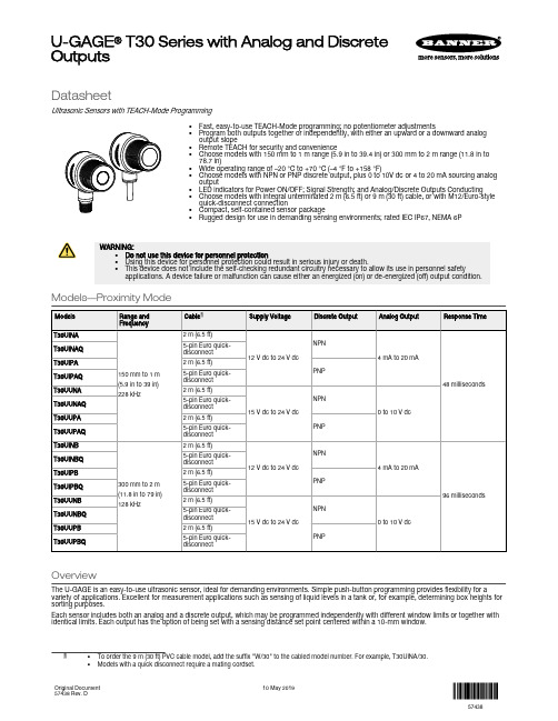
DatasheetUltrasonic Sensors with TEACH-Mode Programming•Fast, easy-to-use TEACH-Mode programming; no potentiometer adjustments•Program both outputs together or independently, with either an upward or a downward analogoutput slope•Remote TEACH for security and convenience•Choose models with 150 mm to 1 m range (5.9 in to 39.4 in) or 300 mm to 2 m range (11.8 in to78.7 in)•Wide operating range of –20 °C to +70 °C (–4 °F to +158 °F)•Choose models with NPN or PNP discrete output, plus 0 to 10V dc or 4 to 20 mA sourcing analogoutput•LED indicators for Power ON/OFF; Signal Strength; and Analog/Discrete Outputs Conducting•Choose models with integral unterminated 2 m (6.5 ft) or 9 m (30 ft) cable, or with M12/Euro-stylequick-disconnect connection•Compact, self-contained sensor package•Rugged design for use in demanding sensing environments; rated IEC IP67, NEMA 6PWARNING:•Do not use this device for personnel protection•Using this device for personnel protection could result in serious injury or death.•This device does not include the self-checking redundant circuitry necessary to allow its use in personnel safety applications. A device failure or malfunction can cause either an energized (on) or de-energized (off) output condition.Models—Proximity ModeOverviewThe U-GAGE is an easy-to-use ultrasonic sensor, ideal for demanding environments. Simple push-button programming provides flexibility for a variety of applications. Excellent for measurement applications such as sensing of liquid levels in a tank or, for example, determining box heights for sorting purposes.Each sensor includes both an analog and a discrete output, which may be programmed independently with different window limits or together with identical limits. Each output has the option of being set with a sensing distance set point centered within a 10-mm window.U-GAGE® T30 Series with Analog and DiscreteOutputsFeatures and IndicatorsU-GAGE Figure 1. U-GAGE T30 Series sensor programming push buttons and indicatorsNote: All LED indicators momentarily turn off when the sensor changes state between Program and Run modes.The U-GAGE sensor has four LED indicators. The red Signal LED indicates the strength and condition of the sensor's incoming signal. Each amberOutput LED, whether analog or discrete, turns on when a target is sensed within the programmed window limits. The green Power ON/OFF LED indicates the operating status of the sensor. There are two modes of indication for the LED indicators: Run Mode and Program Mode.In Run mode:In Program mode:WiringNPN*It is recommended that the shield wire be connected to either earth ground or DC common.–+ PNP*It is recommended that the shield wire be connected to either earth ground or DC common.–+Cabled wiring diagrams are shown. Quick disconnect wiring diagrams are functionally identical.Configuring a Sensor Window LimitsWindow limits can be taught to the sensor in several ways, using either the push buttons on the back of the sensor or remote input.Note: When the sensor changes state between PROGRAM and RUN modes, all of the LED indicators turn OFF momentarily,before the appropriate LEDs come ON as described below. The sensing window limits expand temporarily to full scale (max range) during PROGRAM mode.Remote InputTo program the sensor remotely or to disable the keypad, use the Remote Programming function. In addition to programming the sensor, use the remote input to disable the buttons for security, preventing unauthorized or accidental programming changes. Connect the gray wire of the sensor to +12 V dc to 24 V dc, with a remote programming switch connected between them.Note: The impedance of the remote teach input is 55 kΩ.Programming is accomplished by following the sequence of input pulses. The duration of each pulse (corresponding to a push button “click”), and the period between multiple pulses, are defined as: 0.04 seconds < T < 0.8 seconds.Note: To exit PROGRAM mode without saving any changes, hold the Remote line high > 2 seconds (before teaching the second limit). The sensor reverts to the last saved program.LimitOutput 2 Limits OnlyLimitLimitPush Button Locked out(or Enabled)Output 1Limits OnlyLimit Both OutputsTogetherPush ButtonLockout (or Enable)0.04 sec < T < 0.8 secFigure 2. Timing programs for remote TEACH programmingGeneral Notes on Configuration•The sensor returns to Run mode if the first TEACH condition is not registered within 120 seconds.•After the first limit is taught, the sensor remains in Program mode until the TEACH sequence is finished.•To exit PROGRAM mode without saving any changes, press and hold the programming push button > 2 seconds or hold the Remote line high > 2 seconds (before teaching the second limit). The sensor reverts to the last saved program.Configuring Limits for Either Analog or Discrete OutputNote: To exit PROGRAM mode without saving any changes, press and hold the programming push button > 2 seconds or hold the Remote line high > 2 seconds (before teaching the second limit). The sensor reverts to the last saved program.1.Choose the output for the first set of window limits (analog or discrete).2.Configure the first limit.3.Teach the second limit.4.Repeat for the other output (analog or discrete) if a second output is desired.Configure Analog or Discrete Limits Using the Auto-Zero FeatureFor some applications, a sensing distance set point centered within a minimum sensing window may be required. The TEACH procedure for this application is simple: configuring the same limit twice causes the sensor to program a 10-mm window centered on the position taught (position ±5mm).Note: The sensor allows for some forgiveness in this procedure. If the two limits are not exactly the same (but closer than the minimum 10-mm window required), the sensor places the set point at the average of the two limits.Configuring Identical Limits for Both Analog and Discrete Outputs SimultaneouslyTo set both the analog and the discrete outputs at exactly the same limits, both may be set simultaneously.1.Enter PROGRAM mode.2.Configure the first limit.3.Teach the second limit.Push Button LockoutAnalog OutputThe U-GAGE T30 Series series sensor may be configured for either a positive or a negative output slope, based on which condition is taught first (see Figure 3 on page 6). If the near limit is taught first, the slope is positive; if the far limit is taught first, the slope is negative. Banner’s scalable analog output automatically distributes the output signal over the width of the programmed sensing window.The U-GAGE T30 Series also features a 2-second hold upon loss of the received analog signal, which is useful for harsh and unstable applications.In the event of analog signal loss for longer than 2 seconds, the analog output goes to 3.6 mA or 0 V dc, which may be used to trigger an alarm.Current-Sourcing Models Target Position Positive SlopeNear WindowFar WindowA n a l o g O u t p u t (m A )204Negative SlopeVoltage-Sourcing ModelsTarget PositionPositive SlopeNearWindowFar WindowV o l t a g e O u t p u t (V d c )100Negative SlopeFigure 3. Positive and Negative Output SlopesNote: The analog current output tracks slightly past each window limit (from 3.8 to 20.5 mA).Self-Diagnostic Error ModeIn the unlikely event of a microprocessor memory error, all of the LEDs will flash in sequence. If this occurs, the setup parameters have been lost and the sensor may be corrupt. Contact Banner Engineering for further information.SpecificationsProximity Mode RangeA suffix models: 150 mm (5.9 in) minimum near limit; 1 m (39 in) maximum far limitB suffix models: 300 mm (11.8 in) minimum near limit; 2 m (79 in) maximum far limit Supply VoltageCurrent-sourcing analog output models: 12 V dc to 24 V dc (10% maximum ripple) at 90 mA, exclusive of loadVoltage-sourcing analog output models: 15 V dc to 24V dc (10% maximum ripple) at 90 mA, exclusive of load Supply Protection CircuitryProtected against reverse polarity and transient voltages Output ConfigurationsDiscrete (switched) output: SPST solid-state switch conducts when target is sensed within sensing window; choose NPN or PNP modelsAnalog output: Choose 0 V dc to 10 V dc sourcing or 4 mA to 20 mA sourcing output models; output slope may be selected via TEACH sequence (see Window Limits on page 3)Output RatingsDiscrete (switched) output: 100 mA maximumOff-state leakage current: less than 5 microampsOn-state saturation voltage: less than 1 V at 10 mA and less than 1.5 V at 100 mA Analog output:Voltage sourcing: 0 V dc to 10 V dc (at 1K Ω minimum resistance)Current sourcing: 4 to 20 mA, 1 Ω to Rmax Rmax = V supply - 7V / 20 mA Output Protection CircuitryProtected against output short-circuit, continuous overload, transient overvoltages,and false pulse on power-up Output Response Time Discrete output:“A” suffix models: 48 milliseconds “B” suffix models: 96 milliseconds Analog output:“A” suffix models: 48 milliseconds average, 16-millisecond update “B”suffix models: 96 milliseconds average, 32-millisecond update ConstructionMolded reinforced thermoplastic polyester housingSensing PerformanceNote: Specified using a 10 cm × 10 cm aluminum target at 25 ºC under fixed sensing conditions.Analog sensing resolution: ±0.25% of measured distance Analog linearity: ±0.5% of full-scale sensing range Sensing repeatability: ±0.25% of distance Minimum window size: 10 mm (0.4 in)Hysteresis of discrete output: 2.5 mm (0.10 in)AdjustmentsSensing window limits (analog or discrete): TEACH-mode programming of near and far window limits may be set using the push buttons on the sensor or remotely via TEACH input (see Configuring a Sensor on page 3). Discrete and analog window limits may be programmed separately, or together.Analog output slope: the first limit taught is assigned to the minimum output value (4mA or 0V)Environmental RatingLeakproof design is rated IEC IP67; NEMA 6P Connections2 m (6.5 ft) or 9 m (30 ft) 5-conductor PVC-covered attached cable, or 5-pin Euro-style quick-disconnect fitting Operating ConditionsTemperature: –20 °C to +70 °C (–4 °F to +158 °F)100% maximum relative humidity Application NotesObjects passing inside the specified near limit will produce a false response.Note: For more information about out-of-range and signal loss response of the analog output, see Analog Output on page 5.Vibration and Mechanical ShockAll models meet MIL-STD-202F, Method 201A (Vibration: 10 Hz to 60 Hz maximum,0.06 inch (1.52 mm) double amplitude, 10G maximum acceleration) requirements. Also meets IEC 60947-5-2 (Shock: 30G 11 ms duration, half sine wave) requirements.CertificationsDimensionsM30 x 1.5ThreadQuick-Disconnect ModelsPerformance Curves00200 mm (8.0 in)400 mm (16.0 in)600 mm (24.0 in)800 mm (32.0 in)1000 mm (40.0 in)50501001001501502002002.0 in 2.0 in 4.0 in4.0 in 6.0 in 6.0 in8.0 in 8.0 in DISTANCEW I D T H (m m )Figure 4. A Models 00400 mm (16.0 in)800 mm (32.0 in)1200 mm (48.0 in)1600 mm (64.0 in)2000 mm (80.0 in)10010020020030030040040004.0 in 4.0 in 8.0 in 8.0 in 12.0 in 12.0 in16.0 in 16.0 inDISTANCEWI D T H (m m )Figure 5. B Models05050100100150150200200(8.0 in)(16.0 in)(24.0 in)(32.0 in)(40.0 in)2.0 in 2.0 in 4.0 in4.0 in 6.0 in 6.0 in8.0 in 8.0 in DISTANCE W I D T H (m m )Figure 6. A Models 010*******200300300400400DISTANCE400 mm (16.0 in)800 mm (32.0 in)1200 mm (48.0 in)1600 mm (64.0 in)2000 mm (80.0 in)04.0 in 4.0 in 8.0 in 8.0 in 12.0 in12.0 in16.0 in 16.0 inW I D T H (m m )Figure 7. B ModelsAccessories CordsetsBracketsAll measurements are in mm.Banner Engineering Corp. Limited WarrantyBanner Engineering Corp. warrants its products to be free from defects in material and workmanship for one year following the date of shipment. Banner Engineering Corp. will repair or replace, free of charge, any product of its manufacture which, at the time it is returned to the factory, is found to have been defective during the warranty period. This warranty does not cover damage or liability for misuse, abuse, or the improper application or installation of the Banner product.THIS LIMITED WARRANTY IS EXCLUSIVE AND IN LIEU OF ALL OTHER WARRANTIES WHETHER EXPRESS OR IMPLIED (INCLUDING, WITHOUT LIMITATION, ANY WARRANTY OF MERCHANTABILITY OR FITNESS FOR A PARTICULAR PURPOSE), AND WHETHER ARISING UNDER COURSE OF PERFORMANCE, COURSE OF DEALING OR TRADE USAGE.This Warranty is exclusive and limited to repair or, at the discretion of Banner Engineering Corp., replacement. IN NO EVENT SHALL BANNER ENGINEERING CORP. BE LIABLE TO BUYER OR ANY OTHER PERSON OR ENTITY FOR ANY EXTRA COSTS, EXPENSES, LOSSES, LOSS OF PROFITS, OR ANY INCIDENTAL, CONSEQUENTIAL OR SPECIAL DAMAGES RESULTING FROM ANY PRODUCT DEFECT OR FROM THE USE OR INABILITY TO USE THE PRODUCT, WHETHER ARISING IN CONTRACT OR WARRANTY, STATUTE, TORT, STRICT LIABILITY, NEGLIGENCE, OR OTHERWISE.Banner Engineering Corp. reserves the right to change, modify or improve the design of the product without assuming any obligations or liabilities relating to any product previously manufactured by Banner Engineering Corp. Any misuse, abuse, or improper application or installation of this product or use of the product for personal protection applications when the product is identified as not intended for such purposes will void the product warranty. Any modifications to this product without prior express approval by Banner Engineering Corp will void the product warranties. All specifications published in this document are subject to change; Banner reserves the right to modify product specifications or update documentation at any time. Specifications and product information in English supersede that which is provided in any other language. For the most recent version of any documentation, refer to: .For patent information, see /patents.。
邦纳 超声波传感器操作说明

QS18U操作按键QS18U 操作将目标物放在第二点位置再给示教线一个负脉冲将目标物放在第一点位置给示教线一个负脉冲远程示教示教成功: 输出灯: 亮黄灯或不亮示教不成功: 输出灯: 继续红灯闪烁将目标物放在第二点位置再按一下按纽示教成功: 输出灯: 红灯闪烁示教不成功: 输出灯: 继续亮红灯将目标物放在第一点位置按一下按纽输出灯:亮红色电源灯:亮绿色(信号好的情况下)亮红色(没有信号)按住按纽保持2S 以上结果按键示教方法两点示教方法传感器就在您设定的两点范围之内进行输出QS18U 操作单点示教方法传感器自动以设定点为中心形成一个20mm 输出窗口将目标物不要移动再给示教线一个负脉冲将目标物放在第一点位置给示教线一个负脉冲远程示教示教成功: 输出灯: 亮黄灯或不亮示教不成功: 输出灯: 继续红灯闪烁将目标物不要移动再按一下按纽示教成功: 输出灯: 红灯闪烁示教不成功: 输出灯: 继续亮红灯将目标物放在第一点位置按一下按纽输出灯:亮红色电源灯:亮绿色(信号好的情况下)亮红色(没有信号)按住按纽保持2S 以上结果按键示教方法QS18U 操作常开/常闭选择给示教线三个负脉冲远程示教常开/常闭相互转换不能实现转换功能结果按键示教方法按键锁定与解锁给示教线四个负脉冲远程示教锁定/解锁相互转换不能实现转换功能结果按键示教方法接线图S18U操作按键S18U 操作将目标物放在第二点位置再给示教线一个负脉冲将目标物放在第一点位置给示教线一个负脉冲远程示教示教成功: 输出灯: 亮黄灯或不亮示教不成功: 输出灯: 继续红灯闪烁将目标物放在第二点位置再按一下按纽示教成功: 输出灯: 红灯闪烁示教不成功: 输出灯: 继续亮红灯将目标物放在第一点位置按一下按纽输出灯:亮红色电源灯:亮绿色(信号好的情况下)亮红色(没有信号)按住按纽保持2S 以上结果按键示教方法两点示教方法传感器就在您设定的两点范围之内进行输出S18U 操作单点示教方法开关量输出的传感器自动以设定点为中心形成一个10mm 输出窗口;模拟量输出的传感器自动以设定点为中心形成一个100mm 输出窗口;将目标物不要移动再给示教线一个负脉冲将目标物放在第一点位置给示教线一个负脉冲远程示教示教成功: 输出灯: 亮黄灯或不亮示教不成功: 输出灯: 继续红灯闪烁将目标物不要移动再按一下按纽示教成功: 输出灯: 红灯闪烁示教不成功: 输出灯: 继续亮红灯将目标物放在第一点位置按一下按纽输出灯:亮红色电源灯:亮绿色(信号好的情况下)亮红色(没有信号)按住按纽保持2S 以上结果按键示教方法S18U 操作常开/常闭选择(只针对开关量)给示教线三个负脉冲远程示教常开/常闭相互转换不能实现转换功能结果按键示教方法按键锁定与解锁给示教线四个负脉冲远程示教锁定/解锁相互转换不能实现转换功能结果按键示教方法接线图T18U操作信号灯传感器正常工作状态亮绿色输出过载绿灯闪烁没有电源不亮作用电源灯声波信号的接收状态闪烁速率正比于接收的信号的强度黄灯闪烁作用信号灯将发射器与接受器对准就可以了T30U双开关量操作传感器正常工作状态亮绿色输出过载绿灯闪烁没有电源不亮作用电源灯表示传感器接受信号的强弱,闪烁越快,信号越强.红灯闪烁表示声波没有返回来不亮作用信号灯哪个开关量有输出,相应的输出灯就会变亮T30U 双开关量操作将目标物放在第二点位置再给示教线一个正脉冲将目标物放在第一点位置给示教线二个正脉冲远程示教示教成功: 电源灯: 亮绿灯示教不成功: 相应输出灯: 继续黄灯闪烁将目标物放在第二点位置,再按一下按纽示教成功: 相应输出灯: 黄灯闪烁示教不成功: 相应输出灯: 继续亮黄灯将目标物放在第一点位置,按一下相应按纽电源灯: 熄灭输出灯: 相应的输出灯亮黄色按住按纽保持2S 以上结果按键示教方法两点示教方法传感器就在您设定的两点范围之内进行输出开关量输出1设定方法T30U 双开关量操作将目标物放在第二点位置再给示教线一个正脉冲将目标物放在第一点位置给示教线一个正脉冲远程示教示教成功: 电源灯: 亮绿灯示教不成功: 相应输出灯: 继续黄灯闪烁将目标物放在第二点位置,再按一下按纽示教成功: 相应输出灯: 黄灯闪烁示教不成功: 相应输出灯: 继续亮黄灯将目标物放在第一点位置,按一下相应按纽电源灯: 熄灭输出灯: 相应的输出灯亮黄色按住按纽保持2S 以上结果按键示教方法两点示教方法传感器就在您设定的两点范围之内进行输出开关量输出2设定方法T30U 双开关量操作单点示教方法传感器自动以设定点为中心形成一个10mm 输出窗口远程示教示教成功: 电源灯: 亮绿灯示教不成功: 相应输出灯: 继续黄灯闪烁将目标物不要移动再按一下相应按纽示教成功: 相应输出灯: 黄灯闪烁示教不成功: 相应输出灯: 继续亮黄灯将目标物放在第一点位置按一下相应的按纽电源灯: 熄灭输出灯: 相应的输出灯亮黄色按住按纽保持2S 以上结果按键示教方法T30U 双开关量操作OUTPUT2在设定检测窗口输出,在设定窗口之外时OUTPUT1互补输出.将目标物放在第二点位置再给示教线一个正脉冲将目标物放在第一点位置给示教线三个正脉冲远程示教示教成功: 电源灯: 亮绿灯示教不成功: 输出灯: 继续黄灯闪烁将目标物放在第二点的位置再按一下按纽示教成功: 输出灯: 黄灯闪烁示教不成功: 输出灯: 继续亮黄灯将目标物放在第一点位置按一下按纽电源灯: 熄灭输出灯: 两个输出灯亮黄色同时按住两个按纽并保持2S 以上结果按键示教方法T30U 双开关量操作OUTPUT2从最近点到设定点进行输出,OUTPUT1在设定点到最远点进行互补输出.将目标物不要移动再给示教线一个正脉冲将目标物放在第一点位置给示教线三个正脉冲远程示教示教成功: 电源灯: 亮绿灯示教不成功: 输出灯: 继续黄灯闪烁将目标物不要移动再按一下相应按纽示教成功: 输出灯: 黄灯闪烁示教不成功: 输出灯: 继续亮黄灯将目标物放在第一点位置按一下按纽电源灯: 熄灭输出灯: 两个输出灯亮黄色同时按住两个按纽并保持2S 以上结果按键示教方法按键锁定与解锁给示教线四个正脉冲远程示教锁定/解锁相互转换不能实现转换功能结果按键示教方法T30U 开关量与模拟量操作传感器正常工作状态亮绿色输出过载绿灯闪烁没有电源不亮作用电源灯表示传感器接受信号的强弱,闪烁越快,信号越强.红灯闪烁表示声波没有返回来不亮作用信号灯哪个输出灯亮表示对应的量有输出T30U 开关量与模拟量操作将目标物放在第二点位置再给示教线一个正脉冲将目标物放在第一点位置给示教线一个正脉冲远程示教示教成功: 电源灯: 亮绿灯示教不成功: 相应输出灯: 继续黄灯闪烁将目标物放在第二点位置,再按一下按纽示教成功: 相应输出灯: 黄灯闪烁示教不成功: 相应输出灯: 继续亮黄灯将目标物放在第一点位置,按一下相应按纽电源灯: 熄灭输出灯: 相应的输出灯亮黄色按住按纽保持2S 以上结果按键示教方法两点示教方法传感器就在您设定的两点范围之内进行输出开关量输出设定方法T30U 开关量与模拟量操作将目标物放在第二点位置再给示教线一个正脉冲将目标物放在第一点位置给示教线二个正脉冲远程示教示教成功: 电源灯: 亮绿灯示教不成功: 相应输出灯: 继续黄灯闪烁将目标物放在第二点位置,再按一下按纽示教成功: 相应输出灯: 黄灯闪烁示教不成功: 相应输出灯: 继续亮黄灯将目标物放在第一点位置,按一下相应按纽电源灯: 熄灭输出灯: 相应的输出灯亮黄色按住按纽保持2S 以上结果按键示教方法两点示教方法传感器就在您设定的两点范围之内进行输出模拟量输出设定方法T30U 开关量与模拟量操作单点示教方法传感器自动以设定点为中心形成一个10mm 输出窗口远程示教示教成功: 电源灯: 亮绿灯示教不成功: 相应输出灯: 继续黄灯闪烁将目标物不要移动再按一下相应的按纽示教成功: 相应输出灯: 黄灯闪烁示教不成功: 相应输出灯: 继续亮黄灯将目标物放在第一点位置按一下相应的按纽电源灯: 熄灭输出灯: 相应的输出灯亮黄色按住按纽保持2S 以上结果按键示教方法T30U 开关量与模拟量操作模拟量与开关量同步设定方法将目标物不要移动再给示教线一个正脉冲将目标物放在第一点位置给示教线三个正脉冲远程示教示教成功: 电源灯: 亮绿灯示教不成功: 输出灯: 继续黄灯闪烁将目标物放在第二点位置,再按一下按纽示教成功: 输出灯: 黄灯闪烁示教不成功: 输出灯: 继续亮黄灯将目标物放在第一点位置按一下按纽电源灯: 熄灭输出灯: 两个输出灯亮黄色同时按住两个按纽并保持2S 以上结果按键示教方法T30U 泵入与泵出操作传感器正常工作状态亮绿色输出过载绿灯闪烁没有电源不亮作用电源灯表示传感器接受信号的强弱,闪烁越快,信号越强.红灯闪烁表示声波没有返回来不亮作用信号灯哪个输出灯亮表示对应的量有输出T30U 泵入/泵出操作将目标物放在第二点位置再给示教线一个正脉冲将目标物放在第一点位置给示教线二个正脉冲远程示教示教成功: 电源灯: 亮绿灯示教不成功: 相应输出灯: 继续黄灯闪烁将目标物放在第二点位置再按一下按纽示教成功: 相应输出灯: 黄灯闪烁示教不成功: 相应输出灯: 继续亮黄灯将目标物放在第一点位置按一下相应按纽电源灯: 熄灭输出灯: 相应的输出灯亮黄色按住按纽保持2S 以上结果按键示教方法两点示教方法开关量(泵出)输出1设定方法T30U 泵入/泵出操作将目标物放在第二点位置再给示教线一个正脉冲将目标物放在第一点位置给示教线一个正脉冲远程示教示教成功: 电源灯: 亮绿灯示教不成功:相应输出灯: 继续黄灯闪烁将目标物放在第二点位置再按一下按纽示教成功: 相应输出灯: 黄灯闪烁示教不成功: 相应输出灯: 继续亮黄灯将目标物放在第一点位置按一下相应按纽电源灯: 熄灭输出灯: 相应的输出灯亮黄色按住按纽保持2S 以上结果按键示教方法两点示教方法开关量(泵入)输出2设定方法T30U 泵入/泵出操作OUTPUT2(泵入)在设定检测窗口最近处和最远处输出OUTPUT1(泵出)在设定检测窗口最近处和最近处输出将目标物放在第二点位置再给示教线一个正脉冲将目标物放在第一点位置给示教线三个正脉冲远程示教示教成功: 电源灯: 亮绿灯示教不成功: 输出灯: 继续黄灯闪烁将目标物放在第二点的位置再按一下按纽示教成功: 输出灯: 黄灯闪烁示教不成功: 输出灯: 继续亮黄灯将目标物放在第一点位置按一下按纽电源灯: 熄灭输出灯: 两个输出灯亮黄色同时按住两个按纽并保持2S 以上结果按键示教方法T30U 泵入/泵出操作按键锁定与解锁给示教线四个正脉冲远程示教锁定/解锁相互转换不能实现转换功能结果按键示教方法接线图T30UX开关量操作T30UX 开关量操作两点示教方法传感器就在您设定的两点范围之内进行输出(常开模式)或者不输出(常闭模式).输出设定方法:将目标物放在第二点位置再给示教线一个负脉冲将目标物放在第一点位置给示教线一个负脉冲远程示教示教成功: 输出灯亮黄灯或不亮,电源灯:亮示教不成功: 输出灯: 继续黄灯闪烁将目标物放在第二点位置再按一下按纽示教成功: 输出灯闪烁示教不成功: 输出灯继续亮将目标物放在第一点位置按一下相应按纽电源灯: 熄灭输出灯: 亮按住开关量设置按纽保持2S 以上结果按键示教方法单点设置方法开关量输出的传感器自动以设定点为中心形成一个±10mm (1米), ±20mm (2米), ±30mm (3米)输出窗口(常开模式),常闭模式输出相反;将目标物不要移动再给示教线一个负脉冲将目标物放在第一点位置给示教线一个负脉冲远程示教示教成功: 输出灯亮黄灯或不亮,电源灯:亮示教不成功: 输出灯: 继续闪烁将目标物不要移动再按一下按纽示教成功: 输出灯闪烁示教不成功: 输出灯: 继续亮将目标物放在第一点位置按一下按纽输出灯:亮电源灯:熄灭按住开关量设置按纽保持2S 以上结果按键示教方法T30UX 开关量操作模拟设置方法:可以用来选择常开/常闭模式,NPN/PNP 输出形式,使用远程示教线进行设置:NPN/常开:给一个负脉冲NPN/常闭:给两个负脉冲PNP/常开:给三个负脉冲PNP/常闭:给四个负脉冲给远程示教两个负脉冲远程示教电源灯:亮退出模式设置模式,传感器返回运行状态.按住模式设置按纽保持2S 以上按纽示教结果:设置成功: 相应的指示灯闪烁.远程示教结果:设置成功:电源灯亮,相应的指示灯亮,传感器返回运行模式.单击模式按纽进行选择您所需要的输出形式,可以选择:NPN:常开NPN:常闭PNP:常开PNP:常闭电源灯:熄灭模式灯:先前设定的模式灯开始闪烁按住模式设置按纽保持2S 以上结果按键示教方法T30UX 开关量操作其它远程设置方法:可以用来选择开启/锁定按键,开启/关闭温度补偿,返回出厂默认设置.给八个负脉冲传感器返回出厂默认设置返回出厂设置温度补偿关闭再给四个负脉冲再给三个负脉冲再给两个负脉冲再给一个负脉冲先给三个负脉冲远程示教温度补偿开启温度补偿开启与关闭按键锁定按键开启按键的开启与锁定结果功能T30UX 开关量操作给示教线四个负脉冲远程示教锁定/解锁相互转换不能实现转换功能结果按键示教方法按键锁定与解锁Q45U开关量操作方法面板的作用5段目标位置显示(N 为近点)示教按纽电源灯红色信号灯黄色输出灯盖子卡槽拨码开关的作用Mode:On = HIGH/LOW (fill level control)Off = ON/OFF (standard presence detect)SWITCH FUNCTION123 -4ON/OFF ModeOutput:On = Normally closed Off = Normally openHIGH/LOW Mode On = Pump Out Off = Pump InResponse(20 ms/ cycle)Switch 3Switch 41 Cycle2 Cycles 8 Cycles 32 CyclesOffOn Off OnOff Off On On1234ON4 Position Right Angle DIP Switch检测窗口的调整绿色灯:亮黄色灯:指示目标物是否在设定的范围内.当目标物在设定范围内时指示灯点亮红色灯:闪烁表示信号的强度,闪烁越快表示信号越强.绿色灯:灭黄色灯:以2HZ 频率闪烁红色灯:闪烁表示信号的强度,闪烁越快表示信号越强.绿色灯:灭黄色灯:常亮红色灯:闪烁表示信号的强度,闪烁越快表示信号越强.按示教按纽指示灯的状态1.按住示教按纽2S 以上进入示教状态(1)给远程示教线保持2S 以上正脉冲进入示教状态2.示教第一点:将目标物放在第一点,单击示教按纽(2)远程示教线给一个正脉冲3.示教第二点:将目标物放在第一点,单击示教按纽(3)远程示教线给一个正脉冲Q45U模拟量操作方法面板的作用5段目标位置显示(N 为近点)示教按纽电源灯红色信号灯黄色输出灯响应时间调整盖子卡槽响应时间的的调整响应时间的调整位置响应时间1 32 4 5 680ms 160ms 320ms 640ms2.56s1.28s拨码开关的作用ON:正斜率输出斜率OFF:负斜率ON:电流输出输出模式OFF:电压输出ON:最小/最大模式选择回波丢失OFF:保持模式ON:最大输出最小/最大输出选择OFF:最小输出检测窗口的调整绿色灯:亮黄色灯:指示目标物是否在设定的范围内.当目标物在设定范围内时指示灯点亮红色灯:闪烁表示信号的强度,闪烁越快表示信号越强.绿色灯:灭黄色灯:以2HZ 频率闪烁红色灯:闪烁表示信号的强度,闪烁越快表示信号越强.绿色灯:灭黄色灯:常亮红色灯:闪烁表示信号的强度,闪烁越快表示信号越强.按示教按纽指示灯的状态1.按住示教按纽2S 以上进入示教状态(1)给远程示教线保持2S 以上正脉冲进入示教状态2.示教第一点:将目标物放在第一点,单击示教按纽(2)远程示教线给一个正脉冲3.示教第二点:将目标物放在第一点,单击示教按纽(3)远程示教线给一个正脉冲Q45UR开关量操作方法Q45UR 面板的作用5段目标位置显示(N 为近点)示教按纽电源灯红色信号灯黄色输出灯盖子卡槽拨码开关的作用ONON OFF OFF ONOFF ON OFF 4mm(±2mm)3mm(±1.5mm)2mm(±1mm)321mm(±0.5mm)检测尺寸2-3响应时间ON:40ms OFF:160ms4常开/常闭ON:常闭OFF:常开1功能开关检测窗口的调整绿色灯:亮黄色灯:指示目标物是否在设定的范围内.当目标物在设定范围内时指示灯点亮红色灯:闪烁表示信号的强度,闪烁越快表示信号越强.绿色灯:灭黄色灯:以2HZ 频率闪烁红色灯:闪烁表示信号的强度,闪烁越快表示信号越强.绿色灯:灭黄色灯:常亮红色灯:闪烁表示信号的强度,闪烁越快表示信号越强.按示教按纽指示灯的状态1.按住示教按纽2S 以上进入示教状态(1)给远程示教线保持2S 以上正脉冲进入示教状态2.示教第一点:将目标物放在第一点,单击示教按纽(2)远程示教线给一个正脉冲3.示教第二点:将目标物放在第一点,单击示教按纽(3)远程示教线给一个正脉冲Q45UR模拟量操作方法面板的作用5段目标位置显示(N 为近点)示教按纽电源灯红色信号灯黄色输出灯响应时间调整盖子卡槽响应时间的的调整响应时间的调整位置响应时间1 32 4 5 610ms 20ms 40ms 80ms320ms160ms拨码开关的作用ON:正斜率输出斜率OFF:负斜率ON:电流输出输出模式OFF:电压输出ON:最小/最大模式选择回波丢失OFF:保持模式ON:最大输出最小/最大输出选择OFF:最小输出检测窗口的调整绿色灯:亮黄色灯:指示目标物是否在设定的范围内.当目标物在设定范围内时指示灯点亮红色灯:闪烁表示信号的强度,闪烁越快表示信号越强.绿色灯:灭黄色灯:以2HZ 频率闪烁红色灯:闪烁表示信号的强度,闪烁越快表示信号越强.绿色灯:灭黄色灯:常亮红色灯:闪烁表示信号的强度,闪烁越快表示信号越强.按示教按纽指示灯的状态1.按住示教按纽2S 以上进入示教状态(1)给远程示教线保持2S 以上正脉冲进入示教状态2.示教第一点:将目标物放在第一点,单击示教按纽(2)远程示教线给一个正脉冲3.示教第二点:将目标物放在第一点,单击示教按纽(3)远程示教线给一个正脉冲QT50U双开关量操作方法。
波士顿家用电器800系列36英寸天然气炉-黑色+黑色钢筋钮说明书
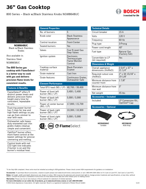
Accessories: To purchase Bosch accessories, cleaners & parts please visit /us/store or call 1-800-944-2904 (Mon to Fri 5 am to 6 pm PST, Sat 6 am to 3 pm PST).36" Gas Cooktop800 Series – Black w/Black Stainless Knobs NGM8648UCNGM8648UCBlack w/Black StainlessKnobs Also available in:Stainless Steel NGM8658UCThe 800 Series gascooktop with FlameSelect ® is a better way to cook with gas and deliversprecision flame levels for consistent results. FlameSelect® offers 9 distinct power levels and delivers precision flame height every time for consistent, repeatable results.Dual-ring power burner has 2 rings for low and high flame settings so you can go from simmer to sear with ease.Dishwasher safe heavy-duty enameled cast iron grates makes cleanup simple and convenient.OptiSim® burner offers more flame control at the lowest settings for precise simmering and melting.Control knob with red LED light line indicates if burner is on and the burner's residual heat.†To be fully ADA compliant, these units must be installed according to ADA guidelines. Please check current ADA requirements for guidance on installation.†FlameSelectHEZ9GR58UCGriddleHEZ298102Wok RingAccessories: To purchase Bosch accessories, cleaners & parts please visit /us/store or call 1-800-944-2904 (Mon to Fri 5 am to 6 pm PST, Sat 6 am to 3 pm PST).Installation Details36" Gas Cooktop800 Series – Black w/Black Stainless Knobs NGM8648UChood, refer to hood manufacturer’s grates B C(940)(≤ 51)(330)0 (≥ 0)Accessories:To purchase Bosch accessories, cleaners & parts please visit /us/store or call 1-800-944-2904 (Mon to Fri 5 am to 6 pm PST, Sat 6 am to 3 pm PST).Installation Details36" Gas Cooktop800 Series – Black w/Black Stainless Knobs NGM8648UCA。