SPD02N50C3中文资料
三品变频器主要参数

Pr010
参数锁定
说明: 0:无效 1:有效 即参数锁定,除本参数外,其余参数不可 修改。 此参数可防止非维护人员误设定其 他参数,参数锁定后,仍可由面板按键改 变运转频率。
Pr011
参数重置
说明: 在参数值因故设置不当或不正常时,可将 此参数设定为 08,恢复出厂值后, 再重新 设置 类比施耐德变频器drC-FCS
PLC 运转选择
外控四段速、外控多段速
Pr080 第二频率设定 Pr081 第三频率设定 Pr082 第四频率设定 Pr083 第五频率设定 Pr084 第六频率设定 Pr085 第七频率设定 Pr086 第八频率设定 外控端子:FUn-PSS-PS2~PS4 预置速度:FUn-PSS-SP2~SP16
Pr003-Pr007用来确定变频器的V/F曲线, 以应对不同的负载特性
Pr009 频率下限
说明: 频率下限主要防止现场人员的误操作,避 免马达因运转频率过低可能产生的过热或 其他机械故障等。 频率下限的设定必须小 于频率上限的设定值。 (频率上限即Pr007最高操作频率) 类比施耐德变频器SEt-LSP、 SEt-HSP
类比施耐德变频器SEt-JPF、JF2
多功能输入端子设置
三品:端子——功能 施耐德:功能——端子
多功能输出端子设置
输出配置:I-O-AOIt、dO(AOV/AOC) 继电器配置:I-O-r1、r2
Pr076
0:普通运行 1:外控四段速 2:外控多段速 3:扰动 4:内控多段速 5:牵伸
三品变频器主要参数说明
Pr000
主频率设定
说明: 在运转频率来源设定为面板操作情况下, 频率以 Pr000 设定值运行。 在多段速运行中,主频率为第一段速频率。 在设定为外控多段速运行时,如果把Pr034 设定为1,即外部端子给定时,则第一段速 由外部端子模拟量给定。 主频率的设定受最大操作频率限制。
稳压二极管型号对照表

稳压二极管型号对照表稳压二极管型号对照表作者: 晨昏 | 浏览数(51) | 评论数(0) | 10-21 21:39 稳压二极管型号对照表200W、230W、300W、350W、420W等各功率电脑电源上的整流部分散热片上的快恢复、肖特基二极管.型号如:1.快恢复二极管:F12C20 F16C20C U20C20C U20D20C2.肖特基二极管:S10C40C S16C40C S20C40C S30D40C S40D45C S40D60C3.光藕BPC817C ,IN5408、FR107/FR104/KBP206等不同种类二极管如何选用1.检波二极管的选用检波二极管一般可选用点接触型锗二极管,例如2AP系列等。
选用时,应根据电路的具体要求来选择工作频率高、反向电流小、正向电流足够大的检波二极管。
2.整流二极管的选用整流二极管一般为平面型硅二极管,用于各种电源整流电路中。
选用整流二极管时,主要应考虑其最大整流电流、最大反向工作电流、截止频率及反向恢复时间等参数。
普通串联稳压电源电路中使用的整流二极管,对截止频率的反向恢复时间要求不高,只要根据电路的要求选择最大整流电流和最大反向工作电流符合要求的整流二极管即可。
例如,1N系列、2CZ系列、RLR系列等。
开关稳压电源的整流电路及脉冲整流电路中使用的整流二极管,应选用工作频率较高、反向恢复时间较短的整流二极管(例如RU系列、EU系列、V系列、1SR系列等)或选择快恢复二极管。
3.稳压二极管的选用稳压二极管一般用在稳压电源中作为基准电压源或用在过电压保护电路中作为保护二极管。
选用的稳压二极管,应满足应用电路中主要参数的要求。
稳压二极管的稳定电压值应与应用电路的基准电压值相同,稳压二极管的最大稳定电流应高于应用电路的最大负载电流50%左右。
4、开关二极管的选用开关二极管主要应用于收录机、电视机、影碟机等家用电器及电子设备有开关电路、检波电路、高频脉冲整流电路等。
开关电源关键元件的各个参数中英文对照表!

开关电源关键元件的各个参数中英文对照表!肖特基二极管Symbol Parameter 中文翻译VRRM Peak repetitive reverse voltage 反向重复峰值电压VRWM Working peak reverse voltage 反向工作峰值电压VR DC Blocking Voltage 反向直流电压VR(RMS) RMS Reverse Voltage 反向电压有效值IF(AV) Average Rectified Forward Current 正向平均电流IR Reverse Current 反向电流IFSM Non-Repetitive Peak Forward Surge Current 浪涌电流VF Forward Voltage 正向直流电压Cj Typical Junction Capactiance 结电容PD Power Dissipation 耗散功率Tj Operating Junction Temperature 工作结温Tstg Storage Temperature Range 存储温度Rth(j-a) Thermal Resistance from Junction to Ambient 结到环境的热阻二极管Symbol Parameter 中文翻译VR Continuous reverse voltage 反向直流电压IF Continuous forward current 正向直流电流VF Forward voltage 正向电压IR Reverse current 反向电流Cd diode capacitance 二极管电容Rd diode forward resistance 二极管正向电阻Ptot total power dissipation 功率总损耗Tj Junction Temperature 结温Tstg storage temperature 存储温度TVS管Symbol Parameter 中文翻译IPP Maximum reverse peak pulse current 峰值脉冲电流VC Clampling voltage 钳位电压IR Maximum reverse leakage current 最大反向漏电流V(BR) Breakdown voltage 击穿电压VRWM Working peak reverse voltage 反向工作峰值电压VF Forward voltage 正向电压IF Forward current 正向电流IT Test current 测试电流可控硅Symbol Parameter 中文翻译VDRM Peak repetitive off-state voltage 断态重复峰值电压VRRM Peak repetitive reverse voltage 反向重复峰值电压IT(RMS) RMS On-state current 额定通态电流ITSM Non repetitive surge peak on-state current 通态非重复浪涌电流IGM Forward peak gate current 控制极重复峰值电流VTM peak forward on-state voltage 通态峰值电压IGT Gate trigger current 控制极触发直流电流VGT Gate trigger voltage 控制极触发电压IH Holding current 维持电流IDRM Peak repetitive off-state current 断态重复峰值电流IRRM Peak repetitive reverse current 反向重复峰值电流PG(AV) Average gate power dissipation 控制极平均功率Tj operating junction temperature range 工作结温Tstg storage temperature range 存储温度稳压管Symbol Parameter 中文翻译VI input voltage 输入电压Vo output voltage 输出电压ΔVo Load regulation 输出调整率ΔVo Line regulation 输入调整率Iq quiescent current 偏置电流ΔIq quiescent current change 偏置电流变化量VN Output noise voltage 输出噪声电压RR Ripple rejection 纹波抑制比Vd dropout voltage 降落电压Isc short circuit current 短路输出电流Ipk peak current 峰值输出电流Topr operating junction temperature range 结温Tstg storage temperature range 存储温度43系列基准源Symbol Parameter 中文翻译VKA Cathode voltage 阴极电压IK Cathode current range(continous) 阴极电流 Iref Reference input current range ,continous 基准输入电流 PD Power dissipation耗散功率Rth(j-a) Thermal resistance from junction toambient结到环境的热阻Topr operating junction temperature range 工作结温 Tstg storage temperature range 存储温度 Vref Reference input voltage基准输入电压ΔVref(dev)Deviation of reference input voltage over full temperature range 全温度范围内基准输入电压的偏差ΔVref/ΔVKA Ratio of change in reference inputvoltage to the change in cathode voltage基准输入电压变化量与阴极电压变化量的比 ΔIref(dev) Deviation of reference input current over full temperature range 全温度范围内基准输入电流的偏差 Imin Minimum cathode current for regulation 稳压时最小负极电流Ioff off-state cathode current 关断状态阴极电流 |ZKA|Dynamic impedance动态阻抗普通晶体管Symbol Parameter 中文翻译VCBO Collector-Base voltage 发射极开路,集电极-基极电压 VCEO Collector-emitter voltage 基极开路,集电极-发射极电压 VEBO Emitter-base voltage 集电极开路,发射极-基极电压 IC Collector current集电极电流 PC Collector power dissipation 集电极耗散功率 Tj Junction temperature 结温 Tstgstorage temperature存储温度V(BR)CBO Collector-Base breakdown voltage发射极开路,集电极-基极反向电压 V(BR)CEOCollector-emitterbreakdown voltage基极开路,集电极-发射极反向电压V(BR)EBO Emitter-base breakdown voltage 集电极开路,发射极-基极反向电压ICBO Collector cut-off current 发射极开路,集电极-基极截止电流IEBO Emitter cut-off current 集电极开路,发射极-基极截止电流ICEOCollector cut-off current基极开路,集电极-发射极截止电流hFE DC current gain 共发射极正向电流传输比的静态值VCEsatCollector-emitter saturationvoltage集电极-发射极饱和电压VBEsat Base-emitter saturation voltage 基极-发射极饱和电压 VBE Base-emitter voltage 基极-发射极电压 fT Transition frequency 特征频率 Cobo Collector output capacitance 共基极输出电容 Cibo Collector input capacitance 共基极输入电容 F Noise figure 噪声系数 Ton Turn-on time 开通时间 Toff Turn-off time 关断时间 Tr Rise time 上升时间 Ts Storage time 存储时间 Tf Fall time 下降时间 TdDelay time延迟时间MOS 管Symbol Parameter 中文翻译 ID Continuous drain current 漏极直流电流 VGS Gate-source voltage 栅-源电压 VDS Drain-source voltage漏-源电压EASsingle pulse avalchane energy单脉冲雪崩击穿能量Rth(j-a) Thermal resistance from junction toambient 结到环境的热阻Rth(j-c) Thermal resistance from junction tocase 结到管壳的热阻V(BR)DSS Drain-source breakdown voltage 漏源击穿电压 V(GS)th Gate threshold voltage 栅源阈值电压 IGSS Gate-body leakage current 漏-源短路的栅极电流 IDSS Zero gate voltage drain current 栅-源短路的漏极电流 rDS(on) Drain-source on-resistance漏源通态电阻 gfs Forward trans conductance 跨导VSD Diode forward voltage 漏源间体内反并联二极管正向压降 Ciss Input capacitance 栅-源电容 Coss Output capacitance漏-源电容 CrssReverse transfer capacitance反向传输电容Rg Gate resistance 栅极电阻td(on) Turn-on delay time 开通延迟时间tr Rise time 上升时间td(off) Turn-off delay time 关断延迟时间tf Fall time 下降时间IDM Pulsed drain current 最大脉冲漏电流PD Power dissipation 耗散功率Tj operating junction temperature range 结温Tstg storage temperature range 存储温度。
施耐德宝光微机保护产品选型手册说明书
Schneider Baoguang关于施耐德宝光施耐德(陕西)宝光电器有限公司(简称SSBEA或施耐德宝光)是施耐德电气有限公司与陕西宝光集团有限公司共同组建的一家专业从事中、系统及相关产品研发、生产和销售的中外合资企业。
高新科技园区。
在世界五百强企业与中国中压电器龙头企业的通力合作下,作为国内中压行业著名的“宝光”品牌真空断路器的唯一合法生产商,施耐德宝光秉承精益生产科学理念,凭借品质过硬、安全可靠的全系列高品质产品和覆盖用户全生命周期的完善服务,帮助用户实现卓越的生产运营绩效和市场竞争力,用品质的“不妥协”实现可持续发展之道。
我们致力于将施耐德宝光打造成为中国卓越和高效的中压断路器和系统的制造平台,依托自身的专业优势,为广大用户和合作伙伴提供领先的总成本和长期全面的安心保障。
目录V5系列新一代微机保护测控装置 (1)产品概述 (1)产品特点 (2)型号及功能说明 (3)保护功能 (4)测控功能 (6)技术参数 (7)典型接线图 (8)外形尺寸及面板开孔尺寸 (11)V5订货选型表 (12)V3系列微机保护测控装置 (13)产品概述 (13)产品特点 (14)型号及功能说明 (15)保护功能 (16)测控功能 (17)技术参数 (18)典型接线图 (19)外形尺寸及面板开孔尺寸 (21)V3订货选型表 (22)V3U微机综合保护装置 (23)产品概述 (23)型号及功能说明 (24)保护功能 (25)测控功能 (26)技术参数 (27)外形尺寸图/典型接线图 (28)后台系统 (29)系统总体结构 (30)V5系列新一代微机保护测控装置是一种用于测量、控制、保护、通讯一体化的智能设备,产品主要用于工业及能源领域对线路、变压器、电动机及电容器的保护测控。
此产品外观时尚、结构精巧、大屏幕液晶显示,图形化中文菜单,四位方向导航盘,操作快捷方便。
内部基于SOC芯片软件方案,32位处理器,并根据硬件进行深度改良优化的嵌入式操作系统,使CPU运行效率更高。
康普斯压缩机分类大全-康普斯压缩机有限公司驻成都办事处

康普斯压缩机分类大全
/shop-20882/一、康普斯SEP系列/双螺杆电动移动式压缩机
SEP210E SEP系列
SEP850G SEP系列
SEP700E SEP系列
二、康普斯SDP系列/双螺杆柴油移动式压缩机
SDP530G SDP系列
SDP350E SDP系列
三、康普斯SMP系列/双螺杆煤矿用防爆压缩机
SMP1060E SMP系列
SMP710 SMP系列
四、康普斯SEF低压系列/双螺杆电动固定式压缩机
SEF210 SEF系列
SEF350 SEF系列
SEF105 SEF系列
SEF35 SEF系列
五、康普斯SEF系列/双螺杆电动固定侧连式压缩机
SEF210 SEF系
SEF350 SEF系
SEF105 SEF系
SEF35 SEF系
六、康普斯SEF系列/双螺杆电动固定直连式压缩机(水、风冷)
SEF210Z
七、康普斯KPS空气净化系统
KPS空气净化系统
康普斯压缩机有限公司驻成都办事处提供。
泽尔顿PDG52M1200D3WN电源防御型塑料外壳电路保护器说明书

Eaton PDG52M1200D3WNEaton Power Defense molded case circuit breaker, Globally Rated, Frame 5, Two Pole, 1200A, 65kA/480V, PXR20D LSIG w/ Modbus RTU, ZSI and Relays, No TerminalsEaton Power Defense molded case circuit breakerPDG52M1200D3WN 786679225912139.7 mm 406.4 mm 209.5 mm 21.32 kg Eaton Selling Policy 25-000, one (1) year from the date of installation of theProduct or eighteen (18) months from thedate of shipment of the Product,whichever occurs first.RoHS Compliant IEC 60947-2UL 489CSACCC MarkedProduct NameCatalog Number UPCProduct Length/Depth Product Height Product Width Product Weight WarrantyCompliancesCertifications1200 AComplete breaker 5Two-polePD5 Global Class A PXR 20D LSIGModbus RTU600 Vac600 VNo Terminals65 kAIC at 480 Vac 50 kAIC Icu/ 30 kAIC Ics/ 105 kAIC Icm @480V Brazil (IEC) 100 kAIC Icu/ 100 kAIC Ics/ 220 kAIC Icm @240V (IEC) 65 kAIC @480/277V (UL)70 kAIC Icu/ 53 kAIC Ics/ 154 kAIC Icm @380-415V (IEC) 15 kAIC Icu/ 7.5 kAIC Ics/ 31.5 kAIC Icm @690V (IEC)30 kAIC Icu/ 25 kAIC Ics/ 63 kAIC Icm @525V South Africa (IEC)100 kAIC @240V (UL) 35 kAIC @600/347V (UL)50 kAIC Icu/ 40 kAIC Ics/ 105 kAIC Icm @440V (IEC)Eaton Power Defense MCCB PDG52M1200D3WN 3D drawing Consulting application guide - molded case circuit breakersAmperage Rating Circuit breaker frame type Frame Number of poles Circuit breaker type Class Trip Type Communication Voltage rating Voltage rating - max Terminals Interrupt rating Interrupt rating range3D CAD drawing packageApplication notesPower Xpert Protection Manager x64BrochuresStrandAble terminals product aidPower Defense molded case circuit breaker selection posterPower Defense brochurePower Defense technical selling bookletCatalogsPower Defense molded case circuit breakers - Frame 5 product aid Power Xpert Release trip units for Power Defense molded case circuit breakersMolded case circuit breakers catalogCertification reportsPDG5 UL authorizationPDG5 CB reportPDG5 CCC certificationEU Declaration of Conformity - Power Defense molded case circuit breakersPDG5 CSA CertificationPower Defense Declaration concerning California’s Proposition 65PDG6 CSA certificationPDG6 CCC certificateInstallation instructionsPower Defense Frame 5 walking beam installation instructions -IL012290ENPower Defense Frame 5 key interlock installation instructions -IL012294ENPower Defense Frame 5 vertical padlockable handle lock hasp installation instructions - IL012283ENPower Defense Frame 5 aux, alarm, shunt trip and uvr instructions(IL012201EN).pdfPower Defense Frame 5 breaker status module installation instructions – IL012307ENPower Defense Frame 4_5_6 high performance flex shaft handle mech assembly instructions - IL012296ENPower Defense Frame 4_5 flex shaft handle mech assembly instructions - IL012284ENPower Defense Frame 2/3/4/5/6 voltage neutral sensor module wiring instructions – IL012316ENInstallation videosPower Defense Frame 5 Aux, Alarm, ST and UVR Animated Instructions.rh1Power Defense Frame 5 Trip Unit Upgrade Relays Board, Animated Instructions.rhPower Defense Frame 5 Trip Unit Replacement Animated Instructions Power Defense Frame 5 UVR Trip How-To VideoPower Defense Frame 5 Shunt Trip, Aux and Alarm Trip How-To Video Power Defense Frame 5 Trip Unit Upgrade Wire Harnesses, Animated Instructions.rhMultimediaPower Defense Frame 5 Trip Unit How-To VideoPower Defense BreakersEaton Power Defense for superior arc flash safetyPower Defense Frame 3 Variable Depth Rotary Handle Mechanism Installation How-To VideoPower Defense molded case circuit breakersPower Defense Frame 2 Variable Depth Rotary Handle Mechanism Installation How-To VideoPower Defense Frame 6 Trip Unit How-To VideoSpecifications and datasheetsEaton Specification Sheet - PDG52M1200D3WNTime/current curvesPower Defense time current curve Frame 5 - PD5White papersMaking a better machineIntelligent power starts with accurate, actionable dataImplementation of arc flash mitigating solutions at industrial manufacturing facilitiesMolded case and low-voltage power circuit breaker healthSingle and double break MCCB performance revisitedIntelligent circuit protection yields space savingsMolded case and low-voltage breaker healthSafer by design: arc energy reduction techniquesEaton Corporation plc Eaton House30 Pembroke Road Dublin 4, Ireland © 2023 Eaton. All Rights Reserved. Eaton is a registered trademark.All other trademarks areproperty of their respectiveowners./socialmedia。
爱立信PDG23N0150P2MN电源保护筋胶电路保护器说明书

Eaton PDG23N0150P2MNEaton Power Defense molded case circuit breaker, Globally Rated, Frame 2, Three Pole, 150A, 85kA/480V, PXR25 LSI w/ Modbus RTU and Relays, No TerminalsGeneral specificationsEaton Power Defense molded case circuit breakerPDG23N0150P2MN 78667927094388.9 mm 152.4 mm 104.6 mm 1.82 kg Eaton Selling Policy 25-000, one (1) year from the date of installation of theProduct or eighteen (18) months from thedate of shipment of the Product,whichever occurs first.RoHS Compliant UL 489IEC 60947-2CCC MarkedCSAProduct NameCatalog Number UPCProduct Length/Depth Product Height Product Width Product Weight WarrantyCompliancesCertifications150 AComplete breaker 2Three-polePD2 Global Class A PXR 25 LSIModbus RTU600 Vac600 VNo Terminals85 kAIC at 480 Vac 22 kAIC Icu @125 Vdc 150 kAIC @240V (UL) 22 kAIC Icu @250 Vdc65 kAIC Icu/ 40 kAIC Ics/ 143 kAIC Icm @480V Brazil (IEC) 30/25 kAIC @600V (UL/CSA)30/25 kAIC Icu/ 15/13 kAIC Ics @525V South Africa (IEC) 70 kAIC Icu/ 50 kAIC Ics/ 154 kAIC Icm @440V (IEC) 70 kAIC Icu/ 70 kAIC Ics/ 154 kAIC Icm @380-415V (IEC) 85 kAIC @480V (UL)150 kAIC Icu/ 100 kAIC Ics/ 330 kAIC Icm @240V (IEC) 10 kAIC Icu/ 5 kAIC Ics/ 21 kAIC Icm @690V (IEC) 25 kAIC @600V (UL/CSA)Eaton Power Defense MCCB PDG23N0150P2MN 3D drawingAmperage Rating Circuit breaker frame type Frame Number of poles Circuit breaker type Class Trip Type Communication Voltage rating Voltage rating - max Terminals Interrupt rating Interrupt rating range 3D CAD drawing packageApplication notesConsulting application guide - molded case circuit breakersPower Xpert Protection Manager x32Power Xpert Protection Manager x64BrochuresPower Defense technical selling bookletPower Defense brochurePower Defense molded case circuit breaker selection posterPower Defense molded case circuit breakers - Frame 2 product aid CatalogsPower Xpert Release trip units for Power Defense molded case circuit breakersMolded case circuit breakers catalogCertification reportsPDG4 CCC certificationPDG4 CB reportEU Declaration of Conformity - Power Defense molded case circuit breakersPDG2 CB reportPower Defense Declaration concerning California’s Proposition 65 Installation instructionsPower Defense Frame 2 global terminal shield, 3 pole - IL012330EN Power Defense Frame 1-2-3-4 IP door barrier assembly instructions -IL012278ENPower Defense Frame 2 multi wire connector kit -PDG2X3(2)(4)TA2253W instructions - IL012243EN H01Power Defense Frame 2 terminal kit - PDG2X3(2)(4)TA225RF instructions - IL012245EN H01Power Defense Frame 2 tunnel terminal kits - PDG2X1TA225K instructions- IL012239EN H01Power Defense Frame 2 screw terminal_end cap kit, 225A, 3 pole instructions - IL012258EN H01Power Defense Frame 2 Direct Rotary Handle Assy With Interlock Version Instructions (IL012138EN).pdfPower Defense Frame 1 IEC and Frame 2 Rotary Mechanism with NFPA Handle Attachment Instructions (IL012260EN).pdfPower Defense Frame 2 tunnel terminal (aluminum), 50A, 3 pole instructions - IL012236EN H03Power Defense Frame 2 locking devices and handle block instructions - IL012149ENPower Defense Frame 2/3/4/5/6 voltage neutral sensor module wiringinstructions – IL012316ENPower Defense Frame 2 handle mech variable depth rotary handle instructions - IL012136ENPower Defense Frame 2 handle mech direct rotary handle instructions - IL012134ENPower Defense Frame 2 tunnel terminal (aluminum), 100A, 3 pole instructions - IL012237EN H03Power Defense Frame 2 box terminal (steel), 100A, 3 pole instructions - IL012234EN H03Power Defense Frame 2 box terminal (aluminum), 225A, 3 pole instructions - IL012235EN H03Power Defense Frame 2 terminal kit - PDG2X3(2)(4)TA150RF instructions - IL012244EN H01Power Defense Frame 2 tunnel terminal (aluminum), 150A, 3 pole instructions - IL012238EN H03Power Defense Frame 2 PDG2 and PDC(E)9 breaker instructions -IL012106ENPower Defense Frame 2 multi wire connector kit -PDG2X3(2)(4)TA2256W instructions - IL012242EN H01Power Defense Frame 2 clamp terminal (steel), 20A, 3 pole instructions - IL012246EN H03Power Defense Frame 2 shunt trip UVR instructions - IL012130EN Power Defense Frame 2 Bell Alarm Switch Instructions (IL012154EN).pdf Power Defense Frame 2 bell alarm switch instructions - IL012154EN Installation videosPower Defense Frame 2 Locking Devices and Handle Block Animated Instructions.pdf.rhPower Defense Frame 2 TMTU Aux, Alarm, ST and UVR Animated Instructions.rhPower Defense Frame 2 Handle Mech Variable Depth Rotary Handle Animated Instructions.rhPower Defense Frame 2 Bell Alarm with PXR Animated Instructions.pdf.rh Power Defense Frame 2 withTMTU, Shunt Trip_UVR Animated Instructions.rhMultimediaPower Defense Frame 2 Variable Depth Rotary Handle Mechanism Installation How-To VideoPower Defense Frame 2 Aux, Alarm, Shunt Trip, and UVR How-To Video Power Defense Frame 3 Variable Depth Rotary Handle Mechanism Installation How-To VideoPower Defense Frame 2 Direct Rotary Handle Mechanism Installation How-To VideoEaton Corporation plc Eaton House30 Pembroke Road Dublin 4, Ireland © 2023 Eaton. All Rights Reserved. Eaton is a registered trademark.All other trademarks areproperty of their respectiveowners./socialmediaEaton Power Defense for superior arc flash safety Power Defense molded case circuit breakers Power Defense Frame 5 Trip Unit How-To Video Power Defense Frame 6 Trip Unit How-To Video Power Defense Breakers Eaton Specification Sheet - PDG23N0150P2MN Power Defense time current curve Frame 2 - PD2Molded case and low-voltage power circuit breaker health Making a better machineSingle and double break MCCB performance revisited Intelligent power starts with accurate, actionable data Intelligent circuit protection yields space savings Safer by design: arc energy reduction techniques Molded case and low-voltage breaker healthSpecifications and datasheetsTime/current curvesWhite papers。
浦发电子商务微波炉RC22S维修指南说明书

Series Qty
1 1 12 3 1 1 1 1 1 2 4 6 3 1 2 1 2 2 1 1 1
12/06
*Color Code (-)=Not Shown #=Series, Serial Prefix or Run No., N=Not Available
2
Section: DOOR Model: RC22S_P1329103M
Series Qty
2 1 3 1 1 2 2 1 1 2 4 2 2 2 1 4 2 2 2 2 3 8 1 2 1 7 2 1 1 1 4 1 1 2 4 1 1 3 1 2 1 1 1 1 1
12/06
*Color Code (-)=Not Shown #=Series, Serial Prefix or Run No., N=Not Available
Description
WRAPPER-OC (SS) ASSY, ACCESS PANEL (REAR) SCREW *** SCREW COVER LIGHT (SS) SCREW, T F CLIP ASSY, BASE PAN BRACKET,HINGE SUPPORT SCREW, TF SCREW, T F SCREW SCREW, T F TRIM-OC (BRUSHED) SUPPORT-TRAY GRILLE, AIR INLET SCREW, DECORATIVE WASHER, NYLON SHIELD, GREASE TRAY-CERAMIC FLOOR W/SEALER SEALER
8
Section: SUPPLEMENTAL INFORMATION
No. Part No.
1 RS2240003 2 12392758 3 16022019 4 59001132 5 16021751 6 R0193574 7 R0130265 8 12543101 9 12543401 10 12598201 11 59001133 12 59001020 13 12155701 14 12002483
海森尔电源 PDG32N0600E4WN 电源防护塑料包容电路保护器说明书

Eaton PDG32N0600E4WNEaton Power Defense molded case circuit breaker, Globally Rated, Frame 3, Two Pole, 600A, 85kA/480V, PXR20 ARMS LSI w/ Modbus RTU, ZSI and Relays, No TerminalsGeneral specificationsEaton Power Defense molded case circuit breakerPDG32N0600E4WN 786679481530109.1 mm 257.1 mm 138.9 mm 5.2163 kg Eaton Selling Policy 25-000, one (1) year from the date of installation of theProduct or eighteen (18) months from thedate of shipment of the Product,whichever occurs first.RoHS Compliant CCC MarkedUL 489CSAIEC 60947-2Product NameCatalog Number UPCProduct Length/Depth Product Height Product Width Product Weight WarrantyCompliancesCertifications600 AComplete breaker 3Two-polePD3 Global Class A PXR 20 LSI w/ARMSModbus RTU600 Vac600 VNo Terminals85 kAIC at 480 Vac 22 kAIC Icu @250 Vdc 150 kAIC @240V (UL)600 AEaton Power Defense MCCB PDG32N0600E4WN 3D drawing Power Xpert Protection Manager x64Consulting application guide - molded case circuit breakers StrandAble terminals product aidPower Defense molded case circuit breaker selection posterAmperage Rating Circuit breaker frame type Frame Number of poles Circuit breaker type Class Trip TypeCommunication Voltage rating Voltage rating - max Terminals Interrupt rating Interrupt rating range Trip rating 3D CAD drawing packageApplication notesBrochuresPower Defense brochurePower Defense technical selling bookletCatalogsMolded case circuit breakers catalogPower Xpert Release trip units for Power Defense molded case circuit breakersCertification reportsPDG3 45-400A CB reportPDG3 CSA certification 100-400aPDG3 CSA certification 250-600aPDG3 UL authorization 100-400aPDG3 UL authorization 250-600a TMTUPDG3B 450A-600A CB reportEU Declaration of Conformity - Power Defense molded case circuit breakersInstallation instructionsPower Defense Frame 1-2-3-4 IP door barrier assembly instructions -IL012278ENPower Defense Frame 3 interphase barrier - IL012229EN H03Power Defense Frame 3 terminal kit Cat Num PDG3X3(2)(4)TA400RF instructions - IL012251ENPower Defense Frame 3 shunt trip UVR instructions - IL012140EN Power Defense Frame 3 trip unit replacement instructions - IL012157EN Power Defense Frame 3 plug-in adapter installation instructions -IL012311ENPower Defense Frame 3 handle mech direct rotary handle instructions - IL012111ENPower Defense Frame 3 locking devices and handle block instructions - IL012150ENPower Defense Frame 3 terminal spreader assembly instructions -IL012301ENPower Defense Frame 2/3/4/5/6 voltage neutral sensor module wiring instructions – IL012316ENPower Defense Frame 3 Breaker Instructions (IL012107EN).pdfPower Defense Frame 3 multi-tap terminal kit Cat NumPDG3X3(2)(4)TA6006WSW instructions - IL012250ENPower Defense Frame 3 reverse feed connector kit Cat NumPDG3X3(2)(4)TA630RF instructions - IL012253ENPower Defense Frame 3 box terminal installation instructions -IL012299ENPower Defense Frame 3 extendable shaft rotary handle mech -IL012112ENPower Defense Frame 3 adapter kit installation instructions LZM3 to PD3 - IL012227ENPower Defense Frame 4 locking devices and handle block instructions - IL012151ENPower Defense Frame 3 multi wire connector kit -PDG3X3(2)(4)TA4006W and PDG3X3(2)(4)TA4003W instructions-IL012247EN H01Power Defense Frame 3 Direct Rotary Handle Assy With Interlock Version Instructions (IL012139EN).pdfPower Defense Frame 4 shunt trip UVR instructions - IL012129EN Power Defense Frame 3 Aux, Alarm, ST and UVR Animated Instructions.rh Power Defense Frame 3 multi-tap terminal kit Cat NumPDG3X3(2)(4)TA6006W Instructions - IL012248ENPower Defense Frame 3 finger protection assembly installation instructions - IL012279ENPower Defense Frame 3 reverse feed connector kit Cat NumPDG3X3(2)(4)TA400HRF instructions - IL012252ENPower Defense Frame 3 rear connection installation instructions -IL012300ENPower Defense Frame 4 reverse feed connector kit instructions for PDG4X3(2)(4)TA800RF instructions - IL012254ENInstallation videosPower Defense Frame 3 Handle Mech Variable Depth Rotary Handle Animated Instructions.rhPower Defense Frame 3 Shunt Trip_UVR Animated Instructions.pdf.rh Power Defense Frame 3 Locking Devices and Handle Block Animated Instructions.pdf.rhPower Defense Frame 3 Handle Mech Direct Rotary Handle Animated Instructions.rhPower Defense Frame 3 trip unit replacement animated instructions.rhMultimediaPower Defense Frame 3 Aux, Alarm, Shunt Trip, and UVR How-To Video Power Defense Frame 5 Trip Unit How-To VideoPower Defense Frame 3 Variable Depth Rotary Handle Mechanism Installation How-To VideoEaton Power Defense for superior arc flash safetyPower Defense Frame 2 Variable Depth Rotary Handle Mechanism Installation How-To VideoPower Defense molded case circuit breakersPower Defense Frame 6 Trip Unit How-To VideoPower Defense BreakersEaton Corporation plc Eaton House30 Pembroke Road Dublin 4, Ireland © 2023 Eaton. All Rights Reserved. Eaton is a registered trademark.All other trademarks areproperty of their respectiveowners./socialmediaEaton Specification Sheet - PDG32N0600E4WN Power Defense time current curve Frame 3 - PD3Implementation of arc flash mitigating solutions at industrial manufacturing facilitiesIntelligent power starts with accurate, actionable data Single and double break MCCB performance revisited Molded case and low-voltage power circuit breaker health Making a better machineIntelligent circuit protection yields space savings Molded case and low-voltage breaker health Safer by design: arc energy reduction techniquesSpecifications and datasheetsTime/current curvesWhite papers。
实力系列固态开关配件,电线,类型 RCS说明书

RHS00
Electroplated steel 12.3 °C/W (>10W)
44
13.5
81 65 50
2 x M4
Dimensions in mm
Specifications are subject to change without notice (09.11.2021)
Specifications are subject to change without notice (09.11.2021)
5
Solid State Relays Accessories, DIN Adaptors
DIN Adaptors for PCB SSRs
DIN rail adaptor module for mounting RP series SSRs on DIN rail. The RPM1 is intended for max. operational voltage of 250V, whilst the RPM2 can be used up to 600V.
- Packing qty. 10 pcs.
RGHT
- Graphite thermal pad for RG series with adhesive on one side
- Width x Height x Thickness = 14 x 35 x 0.13 mm
- Packing qty. 10 pcs.
3
Solid State Relays Accessories, Thermal Interface
Thermal Pads
Ordering Key
24N60C3中文资料
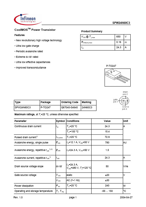
SPW24N60C3Parameter Symbol Conditions Unitmin.typ.max. Thermal characteristicsThermal resistance, junction - case R thJC--0.52K/WR thJA leaded--62Soldering temperature T sold 1.6 mm (0.063 in.)from case for 10 s--260°CElectrical characteristics, at T j=25 °C, unless otherwise specifiedStatic characteristicsDrain-source breakdown voltage V(BR)DSS V GS=0 V, I D=250 µA600--V Avalanche breakdown voltage V(BR)DS V GS=0 V, I D=24.3 A-700-Gate threshold voltage V GS(th)V DS=V GS, I D=1.2 mA 2.13 3.9Zero gate voltage drain current I DSS V DS=600 V, V GS=0 V,T j=25 °C-0.11µAV DS=600 V, V GS=0 V,T j=150 °C--100Gate-source leakage current I GSS V GS=20 V, V DS=0 V--100nADrain-source on-state resistance R DS(on)V GS=10 V, I D=15.4 A,T j=25 °C-0.140.16ΩV GS=10 V, I D=15.4 A,T j=150 °C-0.34-Gate resistance R G f=1 MHz, open drain-0.7-Transconductance g fs |V DS|>2|I D|R DS(on)max,I D=15.4 A-24-SValuesThermal resistance, junction - ambientSPW24N60C3Parameter Symbol Conditions Unitmin.typ.max. Dynamic characteristicsInput capacitance C iss-2800-pF Output capacitance C oss-930-Reverse transfer capacitance C rss-66-Effective output capacitance, energyrelated3)C o(er)-114-Effective output capacitance, timerelated4)C o(tr)-204-Turn-on delay time t d(on)-13-ns Rise time t r-21-Turn-off delay time t d(off)-73-Fall time t f-6-Gate Charge CharacteristicsGate to source charge Q gs-15-nC Gate to drain charge Q gd-49-Gate charge total Q g-105137Gate plateau voltage V plateau- 5.4-V4)Co(tr) is a fixed capacitance that gives the same charging time as C oss while V DS is rising from 0 to 80% V DSS.ValuesV GS=0 V, V DS=25 V,f=1 MHzV DD=480 V,V GS=10 V, I D=24.3 A,R G=3.3 ΩV DD=480 V,I D=24.3 A,V GS=0 to 10 VV GS=0 V, V DS=0 Vto 480 V1) Pulse width limited by maximum temperature Tj,maxonly2) Repetitive avalanche causes additional power losses that can be calculated as PAV=E AR*f.3)Co(er)is a fixed capacitance that gives the same stored energy as C oss while V DS is rising from 0 to 80% V DSS.SPW24N60C3 Definition of diode switching characteristicsP-TO247: OutlineDimensions in mmSPW24N60C3 Published byInfineon Technologies AGBereich KommunikationSt.-Martin-Straße 53D-81541 München© Infineon Technologies AG 1999All Rights Reserved.Attention please!The information herein is given to describe certain components and shall not be considered aswarranted characteristics.Terms of delivery and rights to technical change reserved.We hereby disclaim any and all warranties, including but not limited to warranties of non-infringement, regarding circuits, descriptions and charts stated herein.Infineon Technologies is an approved CECC manufacturer.InformationFor further information on technology, delivery terms and conditions and prices, please contact your nearest Infineon Technologies office in Germany or our Infineon Technologies representatives worldwide (see address list).WarningsDue to technical requirements, components may contain dangerous substances.For information on the types in question, please contact your nearest Infineon Technologies office. Infineon Technologies' components may only be used in life-support devices or systems with the expressed written approval of Infineon Technologies if a failure of such components can reasonablybe expected to cause the failure of that life-support device or system, or to affect the safety or effectiveness of that device or system. Life support devices or systems are intended to be implantedin the human body, or to support and/or maintain and sustain and/or protect human life. If they fail,it is reasonable to assume that the health of the user or other persons may be endangered.。
爱森电源JGS3250NN型号的电源保护类型电路保护器辅助帧说明书
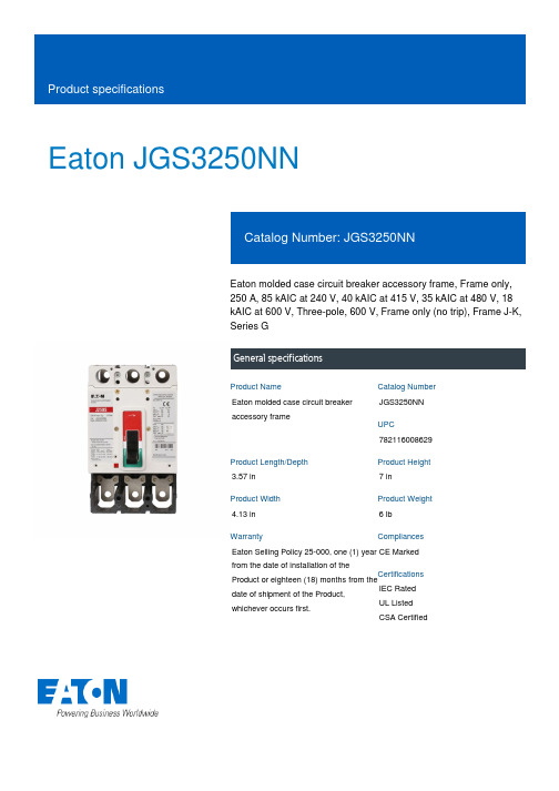
Eaton JGS3250NNEaton molded case circuit breaker accessory frame, Frame only, 250 A, 85 kAIC at 240 V, 40 kAIC at 415 V, 35 kAIC at 480 V, 18 kAIC at 600 V, Three-pole, 600 V, Frame only (no trip), Frame J-K, Series GGeneral specificationsEaton molded case circuit breaker accessory frameJGS3250NN 7821160086293.57 in 7 in4.13 in 6 lb Eaton Selling Policy 25-000, one (1) year from the date of installation of theProduct or eighteen (18) months from thedate of shipment of the Product,whichever occurs first.CE Marked IEC RatedUL ListedCSA CertifiedProduct NameCatalog Number UPCProduct Length/Depth Product Height Product Width Product Weight WarrantyCompliancesCertificationsFrame J-KSeries G18 kAIC at 600 V 40 kAIC at 415 V 85 kAIC at 240 V 35 kAIC at 480 VFrame only600 V250 AFrame only (no trip)Three-pole Application of Multi-Wire Terminals for Molded Case Circuit Breakers Application of Tap Rules to Molded Case Breaker TerminalsMulti-wire lugs product aidCurrent limiting molded case circuit breaker module product aid Comprehensive circuit protection for control panel applicationsPlug-in adapters for molded case circuit breakers product aidPower metering and monitoring with Modbus RTU product aidCircuit breaker motor operators product aidStrandAble terminals product aidMotor protection circuit breakers product aidSeries G MCCB quick selectorCurrent limiting molded case circuit breaker module for series G, JG and CLHigh performance operating handles for Series G circuit breakers product aidMolded case circuit breakers providing higher levels of selective coordination product aidJ-Frame 310+ and L-Frame 310+ Molded-case circuit breakers Breaker service centersMolded case circuit breakers catalogEaton's Volume 4—Circuit ProtectionJG-frame Molded Case Circuit Breaker DrawingAB DE-ION CIRCUIT BREAKER TYPE JG BRKR JG CURR LIMITER 3 POLE OUTLINEInstallation Instructions for Series G J-Frame Circuit BreakersFlex shaft handle installation tutorialNG and ND-Frame molded case circuit breakersMOEM MCCB product selection guideEaton Specification Sheet - JGS3250NNFrame size SeriesInterrupt ratingTypeVoltage rating Amperage Rating Trip Type Number of poles Application notesBrochuresCatalogsDrawingsInstallation instructions MultimediaSpecifications and datasheetsEaton Corporation plc Eaton House30 Pembroke Road Dublin 4, Ireland © 2023 Eaton. All Rights Reserved. Eaton is a registered trademark.All other trademarks areproperty of their respectiveowners./socialmediaSeries G, J-frame Time Current Curve。
SPD07N60C3中文资料

0.00012 0.0004578 0.000645 0.001867 0.004795
0.045
Unit Ws/K
Ptot (t)
Tj R th1
C th 1
C th 2
Rth,n Tcase External Heatsink
C th ,n
Tamb
Page 4
2003-09-16
元器件交易网
VGS VGS Ptot Tj , Tstg
Page 1
Value
Unit
A
7.3
4.6
21.9
230
mJ
0.5
7.3
A
6
V/ns
±20
V
±30
83
W
-55... +150
°C
2003-09-16
元器件交易网
Final data
SPD07N60C3 SPU07N60C3
7V
16
6,5V
ZthJC
ID
10 -1
D = 0.5
12
D = 0.2
D = 0.1
D = 0.05
8
10 -2
D = 0.02 D = 0.01
single pulse
4
10
-3
10
-7
10 -6
10 -5
10 -4
10 -3
s 10 -1
0 0
tp
Page 5
6V
5,5V
Page 3
2003-09-16
元器件交易网
Final data
SPD07N60C3 SPU07N60C3
Electrical Characteristics, at Tj = 25 °C, unless otherwise specified
肖特基二极管常用参数大全
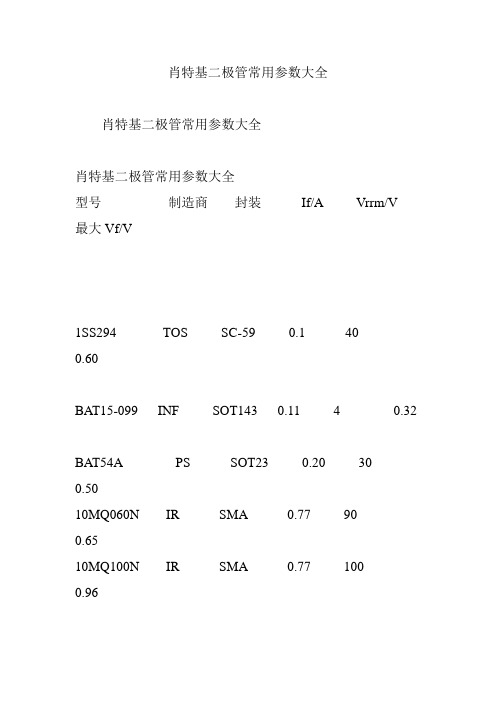
肖特基二极管常用参数大全肖特基二极管常用参数大全肖特基二极管常用参数大全型号制造商封装If/A Vrrm/V最大Vf/V1SS294 TOS SC-59 0.1 400.60BAT15-099 INF SOT143 0.11 4 0.32BAT54A PS SOT23 0.20 300.5010MQ060N IR SMA 0.77 900.6510MQ100N IR SMA 0.77 1000.9610BQ015 IR SMB 1.00 150.34SS12 GS DO214 1.00 20 0.50MBRS130LT3 ON - 1.00 300.3910BQ040 IR SMB 1.00 400.53RB060L-40 ROHM PMDS 1.00 400.55RB160L-40 ROHM PMDS 1.00 400.55SS14 GS DO214 1.00 40 0.50MBRS140T3 ON - 1.00 400.6010BQ060 IR SMB 1.00 600.57SS16 GS DO214 1.00 60 0.7510BQ100 IR SMB 1.00 100 0.78MBRS1100T3 ON - 1.00 100 0.7510MQ040N IR SMA 1.10 40 0.5115MQ040N IR SMA 1.70 40 0.55PBYR245CT PS SOT223 2.00 45 0.4530BQ015 IR SMC 3.00 15 0.3530BQ040 IR SMC 3.00 40 0.5130BQ060 IR SMC 3.00 60 0.5830BQ100 IR SMC 3.00 100 0.79STPS340U STM SOD6 3.00 400.84MBRS340T3 ON - 3.00 40 0.52RB051L-40 ROHM PMDS 3.00 40 0.45MBRS360T3 ON - 3.00 60 0.7030WQ04FN IR DPAK 3.30 40 0.6230WQ06FN IR DPAK 3.30 60 0.7030WQ10FN IR DPAK 3.30 100 0.9130WQ03FN IR DPAK 3.50 30 0.5250WQ03FN IR DPAK 5.50 30 0.5350WQ06FN IR DPAK 5.50 60 0.576CWQ06FN IR DPAK 6.60 600.586CWQ10FN IR DPAK pr 6.60 1000.811N5817 ON 轴向 1.00 20 0.75 1N5818 ON 轴向 1.00 30 0.55SB130 GS 轴向 1.00 30 0.50 1N5819 ON 轴向 1.00 40 0.60 MBR150 ON 轴向 1.00 501.00MBR160 ON 轴向 1.00 601.0011DQ10 IR 轴向 1.10 100 0.8511DQ04 IR 轴向 1.10 40 0.55 11DQ05 IR 轴向 1.10 50 0.58 11DQ06 IR 轴向 1.10 60 0.58MBRS340TR IR SMC 3.00 400.431N5820 ON 轴向 3.00 20 0.85 1N5821 ON 轴向 3.00 30 0.38 1N5822 ON 轴向 3.00 40 0.52MBR360 ON 轴向 3.00 601.00SS32 GS DO214 3.00 20 3.00 SS34 GS DO214 3.00 40 0.50 31DQ10 IR DO201 3.30 100 0.85SB530 GS 轴向 5.00 30 0.57 SB540 GS DO201 5.00 40 0.57 50SQ080 IR 轴向 5.00 80 0.66 50SQ100 IR 轴向 5.00 100 0.66 MBR735 GS TO220 7.50 350.84MBR745 GS TO220 7.50 450.84MBR745 IR TO220 7.50 450.8480SQ040 IR 轴向8.00 40 0.53 STQ080 IR TO220 8.00 80 0.72 8TQ100 TO220 8.00 100 0.72 80SQ040 IR 轴向8.00 40 0.5380SQ035 IR DO204AR 8.00 350.53HFA16PA60C IR TO247CT 8.00 6001.7095SQ015 轴向9.00 15 0.3190SQ040 轴向9.00 40 0.48 10TQ045 TO220 10.00 45 0.57 MBR1035 GS TO220 10.00 350.84MBR1045 ON TO220 10.00 450.84STPS1045F ON ISO220 10.00 45 0.64MBR2060CT ON TO220 10.00 600.85 <P style="TEXT-INDE。
贴片电容电阻参数及详解
公司主营产品相关知识一.贴片电容贴片电容全称:多层(积层,叠层)片式陶瓷电容器,也称为贴片电容,片容。
英文缩写:MLCC。
1.品牌:日系:TDK 、村田(MURATA)、京瓷(Kyocera)、太阳诱电(TAIYO YUDEN)、松下(Panasonic)、罗姆(ROHM)、KOA(KOA SpeerElectronics.Inc)台系:国巨(YAGEO)、华科(WALSIN)韩系:三星(Samsung)国产:风华(FH)、宇阳(E YANG)2.主要参数:容值电压误差材质(精度)尺寸3.各个参数详解:①.容值容值的算法常用容值单位:UF 、 NF 、 PF (微法、纳法、皮法)容值都为千进制(以上前者为后者的1000倍)如:1,000PF =1NF =102 =0.001UF10,000PF =10NF =103 =0.01UF100,000PF =100NF =104 =0.1UF另注:5PF = 509用二位数字表示有效数字,再用一个字母表示数值的量级。
如:1p2表示1.2pF, 220n表示0.22uF,3u3表示3.3uF, 2m2表示2200uF。
另一种表示法,是用三位数字表示电容量,最后用一个字母表示误差。
三位数字中的前两位表示有效值,第三位表示10的n次方,n 一般为1—8。
特殊情况是:当n=9时,不表示10的9次方,而表示为10的 -1次方。
例如:"102"表示10*100=1000pF"223"表示22*1000=22000pF=0.022uF"474"表示47*10000=0.47uF"159"表示15*0.1=1.5pF②.电压各个品牌电容的电压表示方法各不相同。
系列电压有6.3V、10V、16V、25V、50V、100V、200V、500V、1000V、2000V、3000V、 4000V③.误差电容的容值误差通常用字符表示:第一种,绝对误差,通常以电容量的值的绝对误差表示,以PF为单位,即:B代表±0.1PF、C代表±0.25PF、D代表±0.5PF,Y代表±1PF,A代表±1.5PF,V代表±5PF。
三叶源-常规厚膜片式固定电阻器-产品说明书

2018产品说明书PRODUCT MANUAL深圳市叁叶源主要生产被动元器件SMD R‐Chip 电阻,产品尺寸:0402‐1206,阻值范围:1‐22兆欧姆,产品具有高可靠性电极设计、兼容所有焊接制程等特点。
Administrator深圳市叁叶源电子有限公司2018/6/1目录Contents●特点Features3●品名构成Type Designation3●结构Construction4●规格尺寸Dimensions4●负荷下降曲线Derating Curve4●额定值Ratings5●常规TCR值5●高精度TCR±50额定值6●特性Characteristics6●推荐焊盘尺寸Recommend Solder Pad Size9●包装Packaging9●IEC E-24、E-96系列电阻值代码对照表12●厚膜电阻阻值代码及标记规则14●片式电阻器使用说明16●焊接Soldering17■常规厚膜片式固定电阻器General Thick Film Chip Fixed Resistor●特点Features体积小、重量轻Miniature and light weight 适应再流焊与波峰焊Suit for reflow and wave flow solder 电性能稳定,可靠性高Stable electrical capability,high reliability 装配成本低,并与自动贴装设备匹配Low assembly cost,suit for automatic SMT equipment 机械强度高,高频特性优越Superior mechanical and frequency characteristics 符合RoHS 指令要求Compliant with RoHS directive 符合无卤素Halogen free requirement●品名构成Type Designation Single Chip ResistorSY 0402J N 100R P (1)(2)(3)(4)(5)(6)(1)(2)(3)(4)(5)(6)SeriesSize Reslstance Toleiance TCRResistance Packing style SY Thinck Film ST Thinck FilmSA Atuomotive Garde0402060308051206B=±0.1%D=±0.5%F=±1%J=±5%N=Base on Spc E=±50ppm/℃D=±25ppm/℃F=±100ppm/℃G=±200ppm/℃1K 100K 10R 4K71MP=Pager TapeB=Embossed Plastic●结构Construction①陶瓷基板Ceramic Substrate ②背电极Bottom Electrode ③面电极Top Electrode ④电阻体Resistor Layer ⑤一次保护Primary Overcoat ⑥二次保护Secondary Overcoat ⑦端电极Edge Electrode ⑧中间电极Barrier Layer ⑨外部电极External Electrode●规格尺寸Dimensions型号Type 尺寸Dimensions(mm)L W t a b 0402 1.00±0.100.50±0.050.35±0.050.20±0.100.25±0.100603 1.60±0.100.80±0.100.45±0.100.30±0.200.30±0.200805 2.00±0.15 1.25+0.15-0.100.55±0.100.40±0.200.40±0.2012063.10±0.151.55+0.15-0.100.55±0.100.45±0.200.45±0.20●负荷下降曲线Derating Curve额定负荷百分比Percent Rated Load环境温度Ambient temperature(℃)使用温度范围:OperatingTemperature Range:①-55℃~125℃②-55℃~155℃注1:图中曲线适用于适用于0402、0603、0805、1206。
ob2500ncp引脚参数 -回复
ob2500ncp引脚参数-回复引脚是电子设备中非常重要的部分,它们用于连接不同的电子元件,传输信号和能量。
在本文中,我们将探讨OB2500NCP芯片的引脚参数,并详细解释每个引脚的功能和用途。
OB2500NCP是一款高性能的集成电路芯片,主要用于LED驱动器。
它具有多种引脚,每个引脚都有不同的功能和作用。
在下面,我们将一步一步地回答关于OB2500NCP芯片引脚参数的问题。
引脚1:VDDVDD引脚是芯片的电源引脚。
它连接到电源正极,为芯片提供电源。
通常,VDD引脚需要与电源电压相匹配,以确保芯片正常工作。
在OB2500NCP芯片中,VDD引脚的电压范围为3.3V至5V。
引脚2:VINVIN引脚是输入电源引脚。
它用于接收外部电源的电压。
一般情况下,VIN 引脚的电压必须小于或等于VDD引脚的电压。
在OB2500NCP芯片中,VIN引脚的电压范围为0V至3.3V。
引脚3:VOUTVOUT引脚是芯片的输出引脚。
它连接到LED的阴极,用于驱动LED。
通过调节VDD和VIN之间的电压差异,可以改变VOUT引脚的电压输出。
在OB2500NCP芯片中,VOUT引脚的电平可以通过其他引脚进行调节。
引脚4:ADJADJ引脚是模拟调节引脚。
通过改变ADJ引脚的电压,可以调整OB2500NCP芯片输出的电流。
通常,将一个可调电阻与ADJ引脚连接,以实现电流的调节。
ADJ引脚的电压范围为0V至3.3V。
引脚5:ENEN引脚是使能引脚。
当EN引脚处于高电平状态时,芯片工作并输出电流。
当EN引脚处于低电平状态时,芯片停止工作并不输出电流。
EN引脚可以连接到外部控制器,以实现对芯片的控制。
引脚6:ISETISET引脚是电流设置引脚。
通过连接一个电流传感器,可以测量由OB2500NCP芯片输出的电流大小。
ISET引脚的电压与输出电流之间存在一定的关系。
通过调整ISET引脚的电压,可以改变输出电流的大小。
引脚7:OCLIPOCLIP引脚是过流保护引脚。
德欣集团热保护压敏电阻产品规格说明书

SPD Series Specifications德欣集团深圳市德欣电器有限公司SPD全系列规格书产品名称:热保护压敏电阻型号规格: COV25D-COV60D(201K~162K)日期: 2019年6月30日本集团公司旗下总生产面积 60000 平米以上,主营产品压敏芯片及压敏电阻器,电压范围从15V--1800V,产品直径从3mm--80mm均能全系列生产,年产能压敏芯片12亿只以上,压敏电阻器成品8亿只以上,综合年产能20亿只以上,为国内压敏芯片,压敏电阻器产能最大生产商之一,其中(15V-82V)低压压敏芯片,产能,产量,市场占有率位居世界第一。
本公司旗下所生产的全系列产品均有完善的认证体系:具备CQC,UL,CSA,VDE,SGS等多国认证,产品畅销多个国家,全员推行并遵守ISO9001质量管理体系,ISO14001环境管理体系,OHSAS18001职业健康安全管理体系,拥有国家发明专利6项,实用新型专利7项,为高新技术企业。
华北生产基地:山东省德州市平原县经济开发区德欣电器高新科技产业园华南生产基地:惠州市惠阳区秋长将军路合美兴工业园西南生产基地:四川省南充市阆中市七里汉王祠路小微企业孵化园 3 号联系人:林茂发移动电话:136****5669固定电话:*************官方网站:SPD Series Specifications SPD 系列规格说明 Explanation of Part Numbers 型号说明:-Specifications 规格说明:□Varistor Voltage Range压敏电阻动作电压范围 200V~1600V(dc) □Peak Current For 8/20us Current Wave在8/20us电流波形最大通流量 20KA~70KA □Energy Range For 10/1000us Current Wave在10/1000us电流波形的能量范围 250J~2500J □Storage Temperature Range储存温度范围 -40℃~85℃℃ □Operation Ambient Temperature Range作业环境温度范围储存温度范围 -40℃~85℃ □Typical Response Time反应时间 〈25ns □Insulation Resistance绝缘电阻 ≧1000MΩApplications 应用领导域:▇ Protection Of Communication Against Lightning 通信电源防雷保护▇ Industrial Power Distributors 工业配电柜▇ Railway Highway and Air-signal 铁路、公路、航空信号系统▇ Building Power Distributors Input Against Lightning 大楼供电电源入端防雷COV D KC Common Code 产品类别代码DE xin COV Metal Oxide Varistor Surg e Absorber 德欣COV 金属氧化物压敏电阻器 25 32,.34 53 60ChipDiameter 芯片直径 Φ25mm Φ32mm S34mm Φ53mm Φ60mmChip .Shape芯片形状Varistor Voltage 压敏电阻动作电压例如Examples: 47 × 100 = 47 V 47 × 101 = 470 V 11 × 102 = 1100 V47471112Tolerance 误差 K .±10%L .±15% M .±20% OrCustomer Special Requirem entD-Disc 圆形B-Block 塑胶方S-Square 方形Enclosure 包封材质C:Epoxy 环氧树脂 E:Plastic...Case 注塑外壳Tab Style 引出端形状P Planet 平板型 L L Shape L 型 C Radial 圆型L•25D Specifiation*32D Specification(表一:基本尺寸表)(表二:厚度尺寸表) (图1:32D系列简图)SPD Series Specifications *40D Specification(表一:基本尺寸表)(表二:厚度尺寸表) (图1:40D系列简图)*53D Specification(表一:基本尺寸表)(表二:厚度尺寸表) (图1:53D系列简图)*34S Specification(表一:基本尺寸表)(表二:厚度尺寸表) (图1:34S系列简图)*34B (BLOCK VARISTOR) Specification注:未注明公差±0.5mm(图1:34B系列简图)*60B (BLOCK VARISTOR) Specification注:未注明公差±0.5mm(图1:60B系列简图)V-I Curve 电压电流特性曲线:第 21 页 SPD Series Specifications。
- 1、下载文档前请自行甄别文档内容的完整性,平台不提供额外的编辑、内容补充、找答案等附加服务。
- 2、"仅部分预览"的文档,不可在线预览部分如存在完整性等问题,可反馈申请退款(可完整预览的文档不适用该条件!)。
- 3、如文档侵犯您的权益,请联系客服反馈,我们会尽快为您处理(人工客服工作时间:9:00-18:30)。
Cool MOS™ Power TransistorV DS @ T jmax 560V R DS(on)3ΩI D1.8AFeature• New revolutionary high voltage technology • Ultra low gate charge • Periodic avalanche rated • Extreme d v /d t rated• Ultra low effective capacitances • Improved transconductanceTypePackage Ordering Code SPD02N50C3P-TO252-3-1Q67040-S4570Marking 02N50C3Maximum Ratings ParameterSymbol ValueUnitContinuous drain current T C = 25 °C T C = 100 °CI D1.81.1APulsed drain current, t p limited by T jmax I D puls 5.4Avalanche energy, single pulse I D = 1.35 A, V DD = 50 VE AS50mJAvalanche energy, repetitive t AR limited by T jmax 1)I D = 1.8 A, V DD = 50 VE AR 0.07Avalanche current, repetitive t AR limited by T jmax I AR 1.8A Gate source voltage V GS ±20V Gate source voltage AC (f >1Hz)V GS ±30Power dissipation, T C = 25°C P tot 25W Operating and storage temperatureT j , T stg-55... +150°CMaximum RatingsParameter Symbol Value Unit Drain Source voltage slopeV DS = 400 V, I D = 1.8 A, T j = 125 °Cd v/d t50V/nsThermal CharacteristicsParameter Symbol Values Unitmin.typ.max. Thermal resistance, junction - case R thJC --5K/W Thermal resistance, junction - ambient, leaded R thJA--75SMD version, device on PCB: @ min. footprint@ 6 cm2 cooling area 2)R thJA----7550Soldering temperature,1.6 mm (0.063 in.) from case for 10sT sold --260°CElectrical Characteristics, at T j=25°C unless otherwise specifiedParameter Symbol Conditions Values Unitmin.typ.max.Drain-source breakdown voltage V(BR)DSS V GS=0V, I D=0.25mA500--V Drain-Source avalanchebreakdown voltageV(BR)DS V GS=0V, I D=1.8A-600-Gate threshold voltage V GS(th)I D=80µΑ, V GS=V DS 2.13 3.9Zero gate voltage drain current I DSS V DS=500V, V GS=0V,T j=25°C, T j=150°C --0.1-1100µAGate-source leakage current I GSS V GS=20V, V DS=0V--100nA Drain-source on-state resistance R DS(on)V GS=10V, I D=1.1A,T j=25°C T j=150°C --2.77.33-ΩGate input resistance R G f=1MHz, open Drain-12-Electrical Characteristics , at T j = 25 °C, unless otherwise specifiedParameter Symbol Conditions Values Unitmin.typ.max. Transconductance g fs V DS≥2*I D*R DS(on)max,I D=1.1A- 1.8-SInput capacitance C iss V GS=0V, V DS=25V,f=1MHz -190-pFOutput capacitance C oss-80-Reverse transfer capacitance C rss-2-Effective output capacitance,3) energy related C o(er)V GS=0V,V DS=0V to 400V-9-pFEffective output capacitance,4)time relatedC o(tr)-17-Turn-on delay time t d(on)V DD=350V, V GS=0/10V,I D=1.8A, R G=25Ω-10-nsRise time t r-5-Turn-off delay time t d(off)-70-Fall time t f-15-Gate Charge CharacteristicsGate to source charge Q gs V DD=400V, I D=1.8A- 1.5-nC Gate to drain charge Q gd- 4.5-Gate charge total Q g V DD=400V, I D=1.8A,V GS=0 to 10V-9-Gate plateau voltage V(plateau)V DD=400V, I D=1.8A-5-V1Repetitve avalanche causes additional power losses that can be calculated as PAV=E AR*f.2Device on 40mm*40mm*1.5mm epoxy PCB FR4 with 6cm² (one layer, 70 µm thick) copper area for drain connection. PCB is vertical without blown air.3Co(er) is a fixed capacitance that gives the same stored energy as C oss while V DS is rising from 0 to 80% V DSS. 4Co(tr) is a fixed capacitance that gives the same charging time as C oss while V DS is rising from 0 to 80% V DSS.Electrical Characteristics, at T j = 25 °C, unless otherwise specifiedParameter Symbol Conditions Values Unitmin.typ.max. Inverse diode continuousforward currentI S T C=25°C-- 1.8AInverse diode direct current,pulsedI SM-- 5.4 Inverse diode forward voltage V SD V GS=0V, I F=I S-1 1.2VReverse recovery time t rr V R=400V, I F=I S ,d i F/d t=100A/µs -180-nsReverse recovery charge Q rr- 1.2-µC Peak reverse recovery current I rrm-8-A Peak rate of fall of reverserecovery currentdi rr/dt-200-A/µsTypical Transient Thermal CharacteristicsSymbol Value Unit Symbol Value Unittyp.typ.Thermal resistanceR th10.1K/W R th20.184R th30.306R th4 1.207R th50.974R th60.251Thermal capacitanceC th10.00002806Ws/K C th20.0001113C th30.0001679C th40.000547C th50.001388C th60.0191 Power dissipation P tot = f (T C)SPD02N50C3Ptot2 Safe operating areaI D = f( V DS )parameter : D = 0 , T C=25°C3ID3 Transient thermal impedanceZ thJC = f (t p)parameter: D = t p/T-11010101010K/WZthJC4 Typ. output characteristicI D = f (V DS);T j=25°Cparameter: t p = 10 µs, V GSID5 Typ. output characteristicI D = f (V DS); T j=150°C parameter: t p = 10 µs, V GSID6 Typ. drain-source on resistanceR DS(on)=f(I D)parameter: T j=150°C, V GSRDS(on)7 Drain-source on-state resistanceR DS(on) = f (T j)parameter : I = 1.1 A, V = 10 VRDS(on)8 Typ. transfer characteristicsI D= f ( VGS ); V DS≥ 2 x I D x R DS(on)maxparameter: t p = 10 µsID9 Typ. gate charge V GS= f (Q Gate) parameter: I= 1.8 A pulsedVGS10 Forward characteristics of body diodeI F = f (V SD)parameter: T, t p = 10 µsIF11 Avalanche SOAI AR = f (t AR)par.: T j≤ 150 °C4IAR12 Avalanche energyE AS = f (T j)par.: I D = 1.35 A, V DD = 50 VE13 Drain-source breakdown voltage V(BR)DSS = f (T j)SPD02N50C3V(BR)DSS14 Avalanche power lossesP AR = f (f )parameter: E AR=0.07mJ6PAR15 Typ. capacitancesC= f (V DS)parameter: V GS=0V, f=1 MHz16 Typ. C oss stored energyE oss=f(V DS)EDefinition of diodes switching characteristicsP-TO-252-3-1 (D-PAK)2003-10-07Page 11Published byInfineon Technologies AG ,Bereichs KommunikationSt.-Martin-Strasse 53,D-81541 München© Infineon Technologies AG 1999All Rights Reserved.Attention please!The information herein is given to describe certain components and shall not be considered as warranted characteristics.Terms of delivery and rights to technical change reserved.We hereby disclaim any and all warranties, including but not limited to warranties of non-infringement, regarding circuits, descriptions and charts stated herein.Infineon Technologies is an approved CECC manufacturer.InformationFor further information on technology, delivery terms and conditions and prices please contact your nearestInfineon Technologies Office in Germany or our Infineon Technologies Reprensatives worldwide (see address list).WarningsDue to technical requirements components may contain dangerous substances.For information on the types in question please contact your nearest Infineon Technologies Office.Infineon Technologies Components may only be used in life-support devices or systems with the express written approval of Infineon Technologies, if a failure of such components can reasonably be expected to cause the failure of that life-support device or system, or to affect the safety or effectiveness of that device or system Life support devices or systems are intended to be implanted in the human body, or to support and/or maintain and sustain and/or protect human life. If they fail, it is reasonable to assume that the health of the user or other persons may be endangered.元器件交易网。
