arcgis 三维影像制作手册
ARCGIS空间分析指导手册_三_
ARCGIS空间分析实习指导书(三)——三维分析部分本章内容:练习一:在地形表面上叠加影像练习二:污染物在蓄水层中的可视化练习三:土壤污染及甲状腺癌发病率的可视化练习四:创建TIN表面表示地形学习三维分析的最佳办法就是在使用中学习.在本教程的这个练习中,您将学习:用ArcCatalog查找、预览三维数据在ArcScene中添加数据察看数据的三维属性从二维要素与表面中创建新的三维要素从点数据源中创建新的栅格表面从现有要素数据中创建TIN表面为了能够顺利使用本教程,用户的机器上必须安装了ArcGIS及三维扩展模块,并且在本机或网络上安装有本教程所需要的数据.如未在教程指定的默认目录中找到练习数据,请与系统管理员联系,以获取正确的数据路径.拷贝教程数据首先将教程数据拷贝到本机。
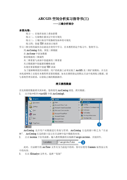
您将使用ArcCatalog浏览、拷贝数据。
1.击开始->程序->ArcGIS中的ArcCatalog8。
ArcCatalog允许用户对数据进行查找与管理。
ArcCatalog左边的窗口称之为“目录树”.ArcCatalog右边的窗口显示在目录树中选中数据的内容。
2.点击location下拉列表框,输入教程数据的安装路径\arcgis\Arctutor,并按回车.此时,目录树中的ArcTutor文件夹为当前选中的项。
你可以使用Contents标签显示其中的内容。
3.右击3DAnalyst文件夹,选择“复制”4.右击本地将拷入数据的文件夹,选择“粘贴”。
此时文件夹拷贝到了本地驱动器中。
下面,在ArcCatalog的目录树中连接3DAnalyst 文件夹进行连接。
5.在本地驱动器中点击3DAnalyst文件夹,并将其拖至ArcCatalog的目录树的最顶层结点中。
此时将在目录树中出现一个本地数据的文件夹连接。
练习一:在地形表面上叠加影像在地形表面上叠加遥感影像,有助于对影像模式及其与地形的相关性的理解。
假如你是加州Death峡谷的地质学家。
Esri ArcGIS 3D地理信息系统用户手册说明书
Create Multipatch Features and Texture Editing380 New York Street Redlands, California 92373 – 8100 USACopyright © 2019 EsriAll rights reserved.Printed in the United States of America.The information contained in this document is the exclusive property of Esri. This work is protected under United States copyright law and other international copyright treaties and conventions. No part of this work may be reproduced or transmitted in any form or by any means, electronic or mechanical, including photocopying and recording, or by any information storage or retrieval system, except as expressly permitted in writing by Esri. All requests should be sent to Attention: Contracts and Legal Services Manager, Esri, 380 New York Street, Redlands, CA 92373-8100 USA.The information contained in this document is subject to change without notice.Using 3D thematic symbology to display features in a sceneTime: 1 hour, 30 minutesOverviewWorking in 3D environments involves more than making features look realistic. It also involves precision, analysis, visual perspectives, and so on. Working in 3D requires new, accurate x, y, and z content, as well as modifying that content, especially when working with real-life scenarios. These aspects are always changing, so you must be able to modify them in a 3D scene environment.As an urban planner, you have been tasked with creating multipatch features and performing texture editing for an urban area. As part of the workflow, you will extrude, edit, and symbolize the building footprints. After converting building footprints to multipatch features, you will apply textures to the buildings to make them as realistic as possible.In this lesson, you will learn to do the following:•Extrude and edit the building footprints•Symbolize the building footprints•Add and configure preset trees•Set a constant elevation•Edit a 3D grid for a building workflow•Create a new feature from existing data•Create a multipatch feature•Perform textured editingDownload the dataFirst, download the data.1. Download the Create-New-Content.zip compressed folder.2. Locate the downloaded file on your computer and extract it to a location you can easily find,such as your Documents folder.3. Open the Create New Content folder.The study area is centered around Redlands, California.Open map packageFirst, you need to create a project using the Blank project template.1.Start ArcGIS Pro and under New, click Local Scene.Note: If you don't have ArcGIS Pro or an ArcGIS account, you can sign up for an ArcGIS free trial.2.On the Quick Access toolbar, click Save or press Ctrl+S to save your project. the project 3D-Editing and choose a suitable location.4.On the Insert tab, in the Project group, click Import Map.5.Browse to or search for Create_New_Content.mpkx to import this local scene.6.Click OK.The Brookside Park scene opens.Extrude the building footprints to represent heightSpend a few minutes familiarizing yourself with the scene content and the 2D and 3D layers organized in the scene contents layer.Apartments bookmark.2.In the Contents pane, click the Building Footprint Brookside layer to select and activate it.3.In the Appearance tab, Extrusion group, click the Type drop-down menu and click Base Height.4.Click the Field drop-down list and select the Building Height field to use this attribute fieldinformation.5.Click the Unit drop-down list and select Feet.The building footprints display with extrusion representing their height. Currently all buildings have a default height of 10 feet.6.Click the Extrusion Expression button to open the Expression Builder window.7.In the Expression Builder window, delete the current [BLDGHEIGHT] expression.8.Type 5 and click OK.The building footprints update showing an extrusion of 5 feet for all buildings.9.Click on the Type drop-down arrow and select None to remove extrusion in preparation for thenext step.Symbolize the building footprints using procedural symbols1.In the Contents pane, click the Building Footprint Brookside layer symbol icon to displaythe Symbology pane.2.In the Format Polygon Symbol pane, click the Properties tab.3.In the Properties tab, click the Layers button.4.Click the Solid fill drop-down menu and select Procedural fill.5.Click the Rule button to open the Select Rule Package browser window.6.Browse for Create New Content > Files > RPK and choose Int_City_2014.rpk.The Int_City_2014 properties pane updates.7.In the Int_City_2014 properties pane, for Type, choose Apartment Building.8.For Building Shape, choose L-Shaped.9.For Total Height, click the database icon to open the Set Attribute Mapping window.10.From the drop-down menu, choose BLDGHEIGHT.11.Click OK.Note: The database icon will be highlighted in blue to indicate that a field is being used.12.In the Symbology pane, click Apply to implement the rule package updates to the buildingfootprints.The building footprints are now symbolized with models that have been derived from the rule package.Experiment with the updated scene and observe how the rule package has applied different roof types and additional parameters to the building footprints. Feel free to update and modify additional rule package settings such as facade texture.13.Save the project.Add trees with preset configurations1.On the Map tab, in the Layer group, click Add Preset and click Realistic Trees.2.In the Add Data dialog box, browse for Create New Content, Brookside Park, and Redlands.gdb >Data and select the TreesA point feature class.3.Click OK.The scene updates to display trees within the footprint of Brookside Park. However, the trees appear to be giant trees as the unit for their height is incorrectly set to meters. Let’s make some corrections to symbology to render the trees more realistically.4.In the Symbology pane for the TreesA layer, set the Unit to Feet.The tree height is derived from an attribute named Crown Height and the values in the attribute field are in feet, but the default symbol unit is meters. You corrected this and the scene updates to display realistic 3D trees that now render with the correct height for each tree.Set constant elevationA constant elevation plane is a level surface that can be used as a reference for the determination of the elevation of geographic features such as buildings and trees. In other words, it’s a baseline from which you can visually determine if a feature is elevated above or below the elevation of the constant plane. It is also useful in 3D editing as it serves as a constant for the defining the z-value of a feature.1.In the Brookside Park scene status bar located in the lower left of the scene, click the DynamicConstraints button to enable this function.2.On the Map tab, in the Navigate group, click Bookmarks and choose Community Center SouthView.ing the Navigator, explore the community center building and surrounding area.4.Click the Building Slab bookmark to display the community center building slab from above.You need to determine the elevation of the building slab to generate a constant elevation plane at the same height as the slab.5.On the Edit tab, in the Elevation group, click the Mode button to enable a constant Z mode.6.In the Elevation group, click the Get Z from View button.7.In the scene, click the Building Slab polygon with the active Get Z from View button.The elevation derived from the slab polygon should be 1,327.6 feet. (Your elevation could vary.)8.Next, change the elevation units to meters (m).The units in meters updates to 404.65 m. For our purposes, we need a constant plane generated at 395 meters.9.In the elevation dialog box, update the value to the exact value of 395, then press Enter.The scene updates and now displays a constant elevation plane at an elevation of 395 meters. This is essentially a level surface taken as reference for the determination of elevations of other geographic features such as buildings and trees.The constant elevation plane displays in the scene as a transparent medium gray overlay.Notice how the constant plane extends north of the building slab, meaning that these areas are at 395 meters, or lower than 395 meters, and that areas south of the slab are higher than 395 meters, as they are not covered by the plane.ing the explore tool, zoom out and tilt the scene to get a better perspective of the extent of thearea covered by the constant elevation plane.Working with the 3D gridBefore editing and creating new 3D features, it is useful to generate a 3D grid that will serve as a reference and guide for the new or updated features. Next, you will setup a 3D grid.1.Click the Building Slab bookmark to display the community center building slab from above.2.In the Brookside Park scene status bar located in the lower left of the scene, click the Grid buttonto enable this function.Note, a display 3D grid will show up in the scene.3.Hold the mouse pointer over the grid button to display the Grid properties pane.4.In the Grid properties pane, click the Set Origin and Rotation button.5.For Origin, snap to and click on the lower left corner of the Building Slab polygon feature.6.Once again, hold the mouse pointer overthe grid button to display the Grid properties pane.7.In the Grid properties pane, update:•Elevation to 395.25 meters.•Rotation to 90 degrees.•Spacing to 5 ft.Now your editing grid should be aligned to the Building Slab polygon feature.8.Save the project.Draw an additional concrete step for the building slabIn the following steps, you will create and design a rectangular concrete step north of the slab to provide an additional step down to a lower grass area. Remember, you have set a constant elevation value of 395 meters. As a result, your newly constructed slab will be constructed at this elevation.1.If necessary, click the Building Slab bookmark to display the community center building slab fromabove.2.On the Edit tab, in the Features group, click Create to activate the Create Features pane.3.In the Create Features pane, expand the Building Slab feature template.4.If the polygon construction tool is not active by default, click it to activate it.5.In the Brookside Park scene status bar in the lower left of the scene, click the snapping button toturn on snapping.6.Hold the mouse pointer over the snapping button to display the Snapping properties pane.In the Snapping properties pane, notice how you can modify the type of snapping from the default.7.Ensure that you have point snapping selected.Next, you will start feature construction.8.For the start point, snap to a grid intersection to the lower left of the building slab with an offsetand left-click to start the sketch.9.Move the pointer north along the grid, parallel with the existing slab to create the first segment.10.Make another left-click to add a vertex, offset from the existing corner.Your first line segment should be created.11.For the second segment, move the pointer east along the grid, parallel with the existing slab.12.Left-click to create the vertex offset from the existing structure.The second line segment should be created.13.For the remaining line segments, right-click to open the construction tool context menu.14.Click Square and Finish to complete the polygon.You should now have a new rectangular polygon feature that steps down to the grass area.15.On the Edit tab, in the Manage Edits group, click Save.16.Click Yes to commit your edits to the geodatabase.17.On the Edit tab in the Elevation group, click the Mode button to disable the constant elevationmode.18.Save the project.Note: You can also repeat this entire section on feature creation, using dynamic constraints to enter the direction, offsets and distance, and so on for the polygon’s line segments. By pressing Tab you will be able to move from each input box to the next one. This workflow is recommended for high-precision workflows in which accuracy and attention to detail is of importance.Multipatch creationTo complete this last step for this lesson we need to open another map package to the existing project.19.On the Insert tab, in the Project group, click Import Map.20.Browse in the same Create New Content lesson folder directory for ME2.mpkx to import thisscene.21.Click OK.22. In Bookmarks for the new scene, select Second.The bookmark updates the extent to display a new retail development named the Packing House District.23.In the scene status bar in the lower left of the scene, click the Grid button to enable.24.In Bookmarks for the new scene, select Four.26.In the Grid properties pane, click the Set Origin and Rotation button. (Your elevation may vary.)27.For Origin, snap to and click the lower left corner of the building from the basemap imagery.28.Hold the mouse pointer over the Grid button to display the Grid properties pane.29.In the Grid properties pane, update:•Elevation to 1,337 ft.•Rotation to 360 degrees.•Spacing to 8 ft.The editing grid should now be aligned to the basemap imagery building.30.In the scene status bar in the lower left of the scene, click both the Constraints and Snappingbuttons to enable them.31.On the Edit tab, in the Features group, click Create to activate the Create Features pane.32.In the Create Features pane, expand the New_Building feature template.33.Click the Create 3D geometry sketch tool.34.Construct the first vertex by snapping to the bottom left corner of the building.35.Next, create a vertex at the right corner of the building.36.Continue north and create a vertex at the upper right corner.37.Add a vertex at the upper left corner.38.Right-click and select Finish.Your new building has been constructed.39.Click the Third bookmark and zoom in to the newly created building.40.Move the pointer to the middle of the newly created multipatch face.A green sphere should display in the middle of the feature.41.Place the pointer directly over the green sphere, which will turn red.42.Left-click and hold on the red sphere to interactively pull the face and press Tab.43.Type “20ft” and press Enter followed by the Finish button or press F2.44.Turn off the Grid and Snapping from the status bar.45.On the Edit tab > Manage Edits group, click Save.46.Click Yes to commit your edits to the geodatabase.47.Save the project.Texture editing1.Make sure the newly created multipatch is still selected; if not, select the new multipatch.2.Click the Modify button under the Edit tab to open the Modify Features pane.3.Select the Multipatch Texture tool.4.Click the Load Texture button.5.Browse in the Create New Content lesson directory for a Textures folder.6.Select Roof.jpg and click Open.Wait until the preview image appears on the bottom part of the tool.7.Place the pointer on the roof face and left-click to place it on that face.8.Once the image is placed on the face, move the pointer back to the preview on the ModifyFeatures pane.9.Move (pan), rotate or scale the preview as needed to fit it correctly on the roof of your newbuilding.Hint: You could also use the three interactive mouse functions. Left-click hold pans, middle-click hold rotates, and right-click hold zoom.10.Add and place the other two textures to the sides by yourself.11.When finished, click Apply on the tool.12.On the Edit tab > Manage Edits group, click Save.13.Click Yes to commit your edits to the geodatabase.14.In the Scene Contents pane, check the Other_Buildings layer.This will display all the additional buildings that were constructed using the same process that you just learned.15.Save your project and close ArcGIS Pro.SummaryIn this lesson, you created a realistic building using multipatch editing tools and textures. In the real world, you could encounter simple to complex building geometry and roof forms. The above workflow can be used for different building types and shapes, with little more than a building footprint, height information, and images for texturing.。
ArcGIS三维建模
ArcGIS三维建模流程概括(1)使用ArcGIS桌面,即ArcMap,加载矢量数据;(2)在ArcMap环境中,利用SketchUp插件工具,将所需要建模的区域导入SketchUp 中。
(3)在SketchUp创建模型。
(4)在SketchUp中将模型转成ArcGIS的Multipatch模型要素文件并保存于Personal GeoDatabase(后面统称为PGDB)中。
环状建模流程图软件环境²ArcGIS桌面产品和服务器产品;²SketchUP 6专业版三维建模软件(建议安装版本6 pro);²SketchUp ESRI插件;²以及图像处理软件Photoshop,用来制作材质文件。
软件安装及配置步骤(1)安装ArcGIS Desktop软件,如ArcInfo。
(过程略)(2)安装草图大师Goolge SketchUp 6 Pro软件。
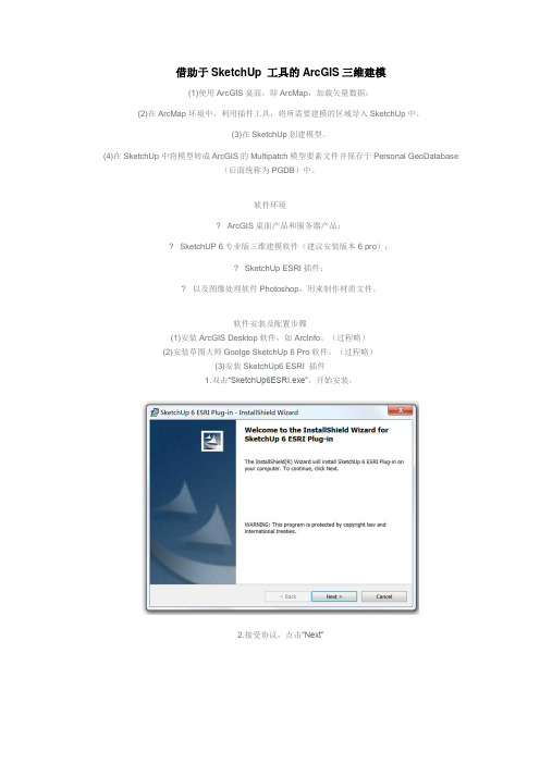
(过程略)(3)安装SketchUp6 ESRI 插件1.双击“SketchUp6ESRI.exe”,开始安装,2.接受协议,点击“Next”3.第一个组件“GIS Plugin”,使用户能够在SketchUp中将模型以Multipatch要素的形式导入GDB。
第二个组件“3D Analyst SketchUp 3D Symbol Support”,用户可以在ArcMap中将GIS数据导入SketchUp中。
上述两个组件的安装位置尽量不要改变,可能会导致在SketchUp中导出3D模型失败。
4.执行组件安装(4)在ArcGIS环境中激活SketchUp6 ESRI插件1.启动ArcMap界面,在工具栏上右键,单击“Customize”2.点击“Add from file”,找到SketchUp ArcGIS Plugin安装目录下的Features To SKP.dll3.添加插件动态库后,在Toolbars项中可以找到SketchUp6的功能项。
ArcGIS三维分析教程
(2)制作3D规划图 E 选定点之后,点击“地理配准—更新显示”
如果配准不满意,可点击“查看连接表”删除
F ,配准好后,点击“地 理配准—纠正”设置“输 出位置”对话框,保存
G 启动ArcScene ,加载“TIN原始地表面”图层和纠正 后的“用地规划图1” (上一步保存的目录和名字) H给规划图附高程 右键“用地规划图1”图层——属性——基本高度;对 话框设置如下图
3.2 TIN地表面的可视化
(1)在ArcScene中查看地面
A启动ArcScene 开始程序中启动
B加载TIN图层
地表面的可视化\原始地表面
C符号化地表面 右键图层—属性,显示“图层属性”对话框 总共有11种符号化类型。
先取消 勾选
再点击添 加,高程
D三维漫游
点击“导航”即可以放大缩小(滚轮),旋转(左 键拖动),平移(按住滚轮拖拉)
D 添加河流道路等其他地图 显示道路河流水塘,打开“图层属性”对话框中的“基
本高度”选项卡,勾选“浮动在自定义表面”上,并选 择“没有基于要素的高度”,使他们附在捕捉不同视角来制作动画
确定一个画面点一次“捕捉视图”,最后点“播放”
3.5 制作三维动画 (2)通过改变一组图层的开关构建动画
应用三:三维场景模拟
ArcMap只能从二维的角度看场景,ArcGIS中提供了 ArcScene和ArcGlobe两种三维场景工具,其中ArcGlobe 适合从全球视角无缝无限量地显示数据,ArcSecne适合 于局部三维透视场景的显示,在规划中较为常用。
使用三维功能需要加载“3D分析”扩展模块: 菜单——自定义——扩展模块,勾选“3D Analyst”
ARCSCENE三维GIS虚拟现实可视化制作教程
ARCSCENE三维GIS虚拟现实可视化制作教程在三维场景中浏览数据更加直观和真实,对于同样的数据,三维可视化将使数据能够提供一些平面图上无法直接获得的信息。
可以很直观地对区域地形起伏的形态及沟、谷、鞍部等基本地形形态进行判读,比二维图形如等高线图更容易为大部分读图者所接受。
ArcScene 是ArcGIS 三维分析模块的一部分,通过在3D Analyst 菜单条中点击按钮打开。
它具有管理3D GIS 数据、进行3D 分析、编辑3D 要素、创建3D 图层以及把二维数据生成3D 要素等功能。
一、要素立体显示有时需要将要素数据在三维场景中以透视图显示出来进行观察和分析。
要素数据与表面数据的不同之处在于,要素数据描述的是离散的对象如点对象、线对象、面对象(多边形)等。
它们通常具有一定的几何形状和属性。
常见的点要素有通信塔台、泉眼等在地图上通常表现为点状符号;线状要素更为常见,如道路、水系、管线等等;多边形要素如湖泊、行政区及大比例尺地形图上的居民地等。
在三维场景中显示要素的先决条件是要素必须被以某种方式赋予高程值或其本身具有高程信息。
因此,要素的三维显示主要有两种方式:1)具有三维几何的要素,在其属性中存储有高程值,可以直接使用其要素几何中或属性中的高程值,实现三维显示;2)对于缺少高程值的要素,可以通过叠加或突出两种方式在三维场景中显示。
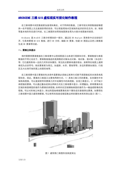
所谓叠加,即将要素所在区域的表面模型的值作为要素的高程值,如将所在区域栅格表面的值作为一幅遥感影像的高程值,可以对其做立体显示;突出则是指根据要素的某个属性或任意值突出要素,如要想在三维场景中显示建筑物要素,可以使用其高度或楼层数这样的属性来将其突出显示(图1)。
图1 建筑物二维图形按高度突出另外,有时研究分析可能需要使用要素的非高程属性值作为三维Z值,在场景中显示要素。
最常见的是在社会、经济领域的应用。
如对某省行政范围内每个市县的经济总量值作为Z 值进行三维立体显示(图2),可直观地观察和分析全省总体的情况。
ArcGIS三维开发帮助文档(VB)
1.ArcOjects 3D开发方法简介一、ArcOjects 3D开发方法简介众所周知,在ArcGIS 3D分析扩展模块中提供了丰富的三维可视化和分析功能:你可以通过不同的视角查看表面数据,对表面数据进行查询,以及对表面数据进行坡度、坡向、视域分析等操作,进行三维动画模拟等等。
其中所涉及的3D对象都是ArcObjects的一部分,针对3D的开发,实际上是ArcObjects的开发,所以具体的开发方法有:基于ArcScene中内嵌的VBA开发;通过VB、VC++等兼容COM的开发语言进行开发新的3D组件和功能。
二、基本的3D对象模型在3D开发中,我们可以用ArcMap对应ArcScene,其中MxDocument对象对应SxDocument 对象,Map对象对应着Scene对象,而相对于Display显示对象,在ArcScene中有SceneGraph 对象。
在对象模型图的顶部是Application对象,从它我们可以执行和应用相关的任务,比如打开文档或者访问和应用相关的其它对象。
在VBA中,我们可以直接获得Application对象:Dim pApp as IApplicaitonSet pApp = Application如果你在VB DLL中实现命令和工具,那么在具体实例化这个类时你可以获得和Application 对象挂接的钩子(hook):Implements ICommandPrivate m_pApp as esriCore.IapplicationPrivate Sub ICommand_OnCreate(ByVal Hook As Object)Set m_pApp = Hook…End Sub有了Application对象,你就可以访问它所包含的其它所有对象了。
比如可以获得SxDocument 对象,而它包含一个Scene对象,Scene对应的SceneGraph对象包含了一个或多个SceneViewer对象,每个SceneViewer对象中有一个Camera对象,它代表了观察点的特性。
ArcGIS三维分析使用指南中文高清版part4
242
ARCGIS 三维分析使用手册
创建关键帧
关键帧是动画的最基本的元素。 一系列的关键帧组装成轨迹。创 建关键帧来创造对象属性的快 照。使用关键帧来创造场景或球 体属性的,或摄影属性(如三维 视图的背景颜色,图层透明度, 或摄影的位置等)的快照。
提示 如何编辑关键帧属性?
使用动画管理器,可以编辑关键帧的 属性。
Animation 工具条介绍
在 ArcScene 和 ArcGlobe 中,Animation 工具条上有用于操 作动画的所有工具。使用这些工具,可以记录浏览,捕获透 视图,保存和输出轨迹,创建视频文件,创建动画组,从路 径创建轨迹以及管理和预览动画等。
创建动画
通过创建动画所包含的轨迹来创建动画。可以通过创建一系 列的关键帧,记录行为,交换图层组的可见度,以及输入限 制运动的路径来创建轨迹。使用动画管理器(Animation Manager)来编辑轨迹和关键帧,并管理动画中的轨迹间如 何相互作用。
创建图层属性的关键帧
1. 更改想要进行捕获的图层属 性。如,打开 3D Effects 工具 条,并给图层设置透明度。
2. 单击 Animation 菜单,并选择 Create Keyframe。
3. 单击 Type 的下拉箭头,并选择 图层。
4. 单击 New。
5. 单击 OK。
6. 单击 Create。
创建场景关键帧属性
1. 右击 Scene layers,并选择 Scene Properties。
2. 设置场景属性或想要捕获的属 性。
3. 打开 Animatoin 工具条,单击 Animation 菜单,并选择 Create Keyframe。
4. 单击 Type 的下拉箭头,并选择 场景。
三维影像制作.pptx
2020-5-29
谢谢阅读
3
(1) 右击图层,在弹出的对话框中,选择 Base Heights(如图标1所示);
(2) 单击Obtain heights for layerfrom suface (如图标2所示),选择您要添加的图层;
(3) 如果两个图层的单位不一致,则要改变 Z Unit Conversion(如图标3所示),同时, 该系数也是用于高程放大因子;
五、三维场景输出 方法一、见下图。
2020-5-29
谢谢阅读
7
在弹出窗口中设置几个参数,用来控制输出图片的 大小。
2020-5-29
设置这两处地方的参数,
以控制输出文件大小。经
多次实验,貌似分辨率最 大 只 能 600 , scene 最 大 只 能6000(实验版本:9.3)
谢谢阅读
8
方法二、
2020-5-29
谢谢阅读
1
二、启动arcscene
2020-5-29
谢谢阅读
2
三、创建三维场景:
1、创建新场景,又称为添加数据。在 ArcScene中,直接单击标准工具上的 图表 即可。
2、定义图层的Z值
一般有三种方法可以用来定义图层的Z 值,即:使用属性设置图层的基准高程;通 过在表面上添加新要素;突出要素。最常用 的是通过在表面上添加新要素,其步骤如下:
2020-5-29
谢谢阅读
10
2020-5-29
谢谢阅读
11
2020-5-29
谢谢阅读
12
2020-5-29
谢谢阅读
13
(4) 单击确定(如图标4所示)!
2020-5-29
谢谢阅读
4
ArcGIS三维建模步骤
借助于SketchUp 工具的ArcGIS三维建模(1)使用ArcGIS桌面,即ArcMap,加载矢量数据;(2)在ArcMap环境中,利用插件工具,将所需要建模的区域导入SketchUp中。
(3)在SketchUp创建模型。
(4)在SketchUp中将模型转成ArcGIS的Multipatch模型要素文件并保存于Personal GeoDatabase(后面统称为PGDB)中。
软件环境ArcGIS桌面产品和服务器产品;SketchUP 6专业版三维建模软件(建议安装版本6 pro);SketchUp ESRI插件;以及图像处理软件Photoshop,用来制作材质文件。
软件安装及配置步骤(1)安装ArcGIS Desktop软件,如ArcInfo。
(过程略)(2)安装草图大师Goolge SketchUp 6 Pro软件。
(过程略)(3)安装SketchUp6 ESRI 插件1.双击“SketchUp6ESRI.exe”,开始安装,2.接受协议,点击“Next”3.第一个组件“GIS Plugin”,使用户能够在SketchUp中将模型以Multipatch要素的形式导入GDB。
第二个组件“3D Analyst SketchUp 3D Symbol Support”,用户可以在ArcMap中将GIS数据导入SketchUp中。
上述两个组件的安装位置尽量不要改变,可能会导致在SketchUp中导出3D模型失败。
4.执行组件安装(4)在ArcGIS环境中激活SketchUp6 ESRI插件1.启动ArcMap界面,在工具栏上右键,单击“Customize”2.点击“Add from file”,找到SketchUp ArcGIS Plugin安装目录下的Features To SKP.dll3.添加插件动态库后,在Toolbars项中可以找到SketchUp6的功能项。
4.选中“SketchUp 6 Tools”组件以后,在桌面上会弹出组件的功能按钮。
ArcGIS三维建模步骤

借助于SketchUp 工具的ArcGIS三维建模(1)使用ArcGIS桌面,即ArcMap,加载矢量数据;(2)在ArcMap环境中,利用插件工具,将所需要建模的区域导入SketchUp中。
(3)在SketchUp创建模型。
(4)在SketchUp中将模型转成ArcGIS的Multipatch模型要素文件并保存于Personal GeoDatabase(后面统称为PGDB)中。
软件环境 ArcGIS桌面产品和服务器产品; SketchUP 6专业版三维建模软件(建议安装版本6 pro); SketchUp ESRI插件; 以及图像处理软件Photoshop,用来制作材质文件。
软件安装及配置步骤(1)安装ArcGIS Desktop软件,如ArcInfo。
(过程略)(2)安装草图大师Goolge SketchUp 6 Pro软件。
(过程略)(3)安装SketchUp6 ESRI 插件1.双击“SketchUp6ESRI.exe”,开始安装,2.接受协议,点击“Next”3.第一个组件“GIS Plugin”,使用户能够在SketchUp中将模型以Multipatch要素的形式导入GDB。
,用户可以在ArcMap中将GIS数据导入SketchUp 第二个组件“3D Analyst SketchUp 3D Symbol Support”中。
上述两个组件的安装位置尽量不要改变,可能会导致在SketchUp中导出3D模型失败。
4.执行组件安装 (4)在ArcGIS环境中激活SketchUp6 ESRI插件1.启动ArcMap界面,在工具栏上右键,单击“Customize”2.点击“Add from file”,找到,找到SketchUp ArcGIS Plugin安装目录下的Features To SKP.dll 3.添加插件动态库后,在Toolbars项中可以找到SketchUp6的功能项。
4.选中“SketchUp 6 Tools”组件以后,在桌面上会弹出组件的功能按钮。
ArcGIS三维开发帮助文档(VB)

1.ArcOjects 3D开发方法简介一、ArcOjects 3D开发方法简介众所周知,在ArcGIS 3D分析扩展模块中提供了丰富的三维可视化和分析功能:你可以通过不同的视角查看表面数据,对表面数据进行查询,以及对表面数据进行坡度、坡向、视域分析等操作,进行三维动画模拟等等。
其中所涉及的3D对象都是ArcObjects的一部分,针对3D的开发,实际上是ArcObjects的开发,所以具体的开发方法有:基于ArcScene中内嵌的VBA开发;通过VB、VC++等兼容COM的开发语言进行开发新的3D组件和功能。
二、基本的3D对象模型在3D开发中,我们可以用ArcMap对应ArcScene,其中MxDocument对象对应SxDocument 对象,Map对象对应着Scene对象,而相对于Display显示对象,在ArcScene中有SceneGraph 对象。
在对象模型图的顶部是Application对象,从它我们可以执行和应用相关的任务,比如打开文档或者访问和应用相关的其它对象。
在VBA中,我们可以直接获得Application对象:Dim pApp as IApplicaitonSet pApp = Application如果你在VB DLL中实现命令和工具,那么在具体实例化这个类时你可以获得和Application 对象挂接的钩子(hook):Implements ICommandPrivate m_pApp as esriCore.IapplicationPrivate Sub ICommand_OnCreate(ByVal Hook As Object)Set m_pApp = Hook…End Sub有了Application对象,你就可以访问它所包含的其它所有对象了。
比如可以获得SxDocument 对象,而它包含一个Scene对象,Scene对应的SceneGraph对象包含了一个或多个SceneViewer对象,每个SceneViewer对象中有一个Camera对象,它代表了观察点的特性。
利用ArcGIS创建逼真三维图

步骤:1.单击开始 > 所有程序〉 ArcGIS > ArcGlobe 10启动ArcGlobe.2.在“ArcGlobe - 启动"对话框中,单击浏览,将地球的默认地理数据库路径设置为:D:\3DAnalyst\3D_Default。
gdb此位置用于存放在教程练习中生成的输出空间数据。
3.接下来,在“ArcGlobe - 启动”对话框中,单击现有Scene > 浏览更多.将出现打开对话框。
1.导航至Exercise9 文件夹。
2.双击London_Start ArcGlobe 文档。
ArcGlobe 文档包含高分辨率影像(由DigitalGlobe QuickBird 公司提供)、一个使用树符号符号化的3D 要素数据集以及一个表示研究区域建筑物的带纹理的3D 多面体(multipatch)数据集.3.单击文件,然后单击另存为。
4.输入globe 文档的名称London.5.单击保存。
设置图层的可见距离范围您可通过为每个图层设置适当的可见距离来优化ArcGlobe 文档的性能。
可通过指定可见距离范围来控制执行缩放操作时图层何时可见.您既可以为整个图层设置最小和最大距离,也可以根据各切片的距离来确定图层的可见性。
“建筑物"图层旁边处于选中状态的复选框在内容列表中不可用.这意味着,显示当前超过了图层的最大可见距离.稍后您将在本练习中更改其他两个图层的最大可见距离。
步骤:1.在内容列表中,右键单击Holborn.jp2 图层,然后单击属性。
2.单击Globe 常规选项卡.3.单击缩放超过下列限制时不显示图层选项。
4.在缩小超过文本框中输入5。
此距离的单位为千米。
5.根据各切片距离检查可见性以启用图层离散部分的距离可见性。
此设置可进一步提高性能,尽管默认情况不启用该设置。
启用该设置后,在图层的距离阈值附近进行浏览时数据的离散切片可见。
6.单击确定。
在最小和最大距离之间,图层将可见。
ARCGIS三维影像制作

六、三维路径飞行 1、调出如右图菜单
(4) 单击确定(如图标4放大缩小,鼠标左 键为改变角度,鼠标中间按住拖动为移动场 景。在下图中,可调节影像的亮度与对比度。
视图质量设置
将此参数调高,否 那么输出图很模糊
【五】三维场景输出 方法【一】见下图。
在弹出窗口中设置几个参数,用来控制输出图片的 大小。
ARCGIS三维影像制作
【二】启动arcscene
【三】创建三维场景:
1、创建新场景,又称为添加数据。在 ArcScene中,直截了当单击标准工具上的 图表即可。
2、定义图层的Z值
一般有三种方法能够用来定义图层的Z 值,即:使用属性设置图层的基准高程;通 过在表面上添加新要素;突出要素。最常用 的是通过在表面上添加新要素,其步骤如下:
(1) 右击图层,在弹出的对话框中,选择 Base Heights(如图标1所示);
(2) 单击Obtain heights for layerfrom suface (如图标2所示),选择您要添加的图层;
(3) 假如两个图层的单位不一致,那么要改 变Z Unit Conversion(如图标3所示),同时, 该系数也是用于高程放大因子;
设置这两处地方的参数, 以控制输出文件大小。经 多次实验,貌似分辨率最 大 只 能 600 , scene最 大 只 能6000(实验版本:9.3)
方法【二】
设置好参数之后,能够采用pdf打印输出。 输出时,设置纸张为较大尺寸,如A0等以上,
分辨率设置低一些,如150以下,如此可避免 出现白线条。
ArcGIS三维建模步骤

借助于SketchUp 工具的ArcGIS三维建模(1)使用ArcGIS桌面,即ArcMap,加载矢量数据;(2)在ArcMap环境中,利用插件工具,将所需要建模的区域导入SketchUp中。
(3)在SketchUp创建模型。
(4)在SketchUp中将模型转成ArcGIS的Multipatch模型要素文件并保存于Personal GeoDatabase(后面统称为PGDB)中。
软件环境ArcGIS桌面产品和服务器产品;SketchUP 6专业版三维建模软件(建议安装版本6 pro);SketchUp ESRI插件;以及图像处理软件Photoshop,用来制作材质文件。
软件安装及配置步骤(1)安装ArcGIS Desktop软件,如ArcInfo。
(过程略)(2)安装草图大师Goolge SketchUp 6 Pro软件。
(过程略)(3)安装SketchUp6 ESRI 插件1.双击“SketchUp6ESRI.exe”,开始安装,2.接受协议,点击“Next”3.第一个组件“GIS Plugin”,使用户能够在SketchUp中将模型以Multipatch要素的形式导入GDB。
第二个组件“3D Analyst SketchUp 3D Symbol Support”,用户可以在ArcMap中将GIS数据导入SketchUp中。
上述两个组件的安装位置尽量不要改变,可能会导致在SketchUp中导出3D模型失败。
4.执行组件安装(4)在ArcGIS环境中激活SketchUp6 ESRI插件1.启动ArcMap界面,在工具栏上右键,单击“Customize”2.点击“Add from file”,找到SketchUp ArcGIS Plugin安装目录下的Features To SKP.dll3.添加插件动态库后,在Toolbars项中可以找到SketchUp6的功能项。
4.选中“SketchUp 6 Tools”组件以后,在桌面上会弹出组件的功能按钮。
arcgis教程_ArcGIS三维分析
14.3 表面分析
表面(包含无数点的区域)通常蕴含了丰富的信息。用户 可能想简单地浏览表面,这是一个从总体上理解表面的好方式, 或者用户可能会对表面上某个感兴趣的特定区域进行详细研究。 例如,用户可能想知道表面上某一点处高度、温度、气压或杀虫 剂浓度等信息的值。用户可能想知道是否在A点的观测者能够看 到B点,或者一条规划的小路有多陡。用户可能对某个水库的库 容或某条山脊的石方感兴趣。或者,用户可能对表面形状的整体 信息感兴趣,这并不是通过对表面进行简单的观察就能立即得到 的信息。例如,用户可能想知道哪些点在相同的高程,表面的哪 些部分有着相同的朝向,哪里的化学污染的浓度最高或者地表下 降得最厉害。
第14章 ArcGIS三维分析
ArcGIS具有一个能为三维可视化、三维分析以及表面 生成提供高级分析功能的扩展模块“3D Analyst “ ,可以用 它来创建动态三维模型和交互式地图,从而更好地实现地理 数据的可视化和分析处理。 使用上述ArcMap软件工具可以对ArcGIS中的矢量数据 进行三维分析操作。本章主要介绍ArcMap软件工具的三维 分析,并在此基础之上讲解如何进行具体的三维操作。
ArcScene是三维分析(3D Analyst)添加的三维可视化应用程 序之一,它们扩展了ArcGIS Desktop的功能,并且扩展了 ArcCatalog和ArcMap的三维功能。 ArcScene允许用户制作具有透视效果的场景,在这个场景中可 以对地理信息系统数据进行浏览和交互。不仅如此,用户还可以在 表面上叠加栅格和矢量数据,并从矢量数据源创建线、面和体。用 户也可以使用ArcScene中的三维分析工具创建和分析表面。 1.ArcScene的用途简介 2.ArcScene中的3D工具 3.ArcGIS表面模型(GRID和TIN)的三维显示 4.二维栅格数据的三维显示 5.二维矢量数据的三维显示
ArcGIS Pro三维教程
ArcGIS Pro三维教程打开工程研究区域为新西兰惠灵顿Kelburn 郊区。
完成导入ArcMap 文档教程后,你将熟悉起始地图。
1.启动ArcGIS Pro 并根据需要进行登录。
2.在起始页的最近工程下方,单击打开其他工程。
注:如果已打开一个工程,请单击功能区上的工程选项卡。
在左侧的菜单项列表中,单击打开。
在打开页面上单击门户,然后单击页面底部的打开其他工程。
1.在打开工程对话框的门户下,单击ArcGIS Online。
注:如果你看到列出的是ArcGIS Enterprise,则必须添加门户连接或设置活动门户(设置为ArcGIS Online)。
或者,你可以从浏览器下载教程数据。
1.在对话框顶部的搜索框中,输入Convert a map to a scene tutorial,然后按Enter 键。
2.在搜索结果列表中,单击将地图转换为场景以选择工程包。
注:如果该名称下不只有一个工程包,请查看所有者列。
选择所有者名称为ArcGISProTutorials的项目。
如果未得到任何结果,请参阅未返回任何搜索结果。
1.单击确定。
此工程将打开Kelburn 郊区的地图视图。
表示步行路径、车行道路和区域划分的图层显示在深灰色的底图之上。
从地图创建场景在ArcGIS Pro 中,3D 地图被称为场景。
可在全球或局部模式下查看所有场景。
在全球模式下,地球被绘制成球体,视点通常是涵盖数千公里的数据。
该视图是大型研究区域的最佳之选。
在局部模式下,地球以视角方式绘制,视点通常是涵盖数万千米的数据。
对于小研究区域,此视图是最佳之选。
在此工程中,你感兴趣的区域非常小。
你需要将地图转换为局部场景。
上图:以新西兰为中心的全球视图。
下图:惠灵顿土地覆盖的局部视图。
1.单击功能区上的视图选项卡。
在窗口组中,单击重置窗格,然后单击重置窗格以进行映射。
此操作可确保内容和目录窗格打开,其他窗格关闭。
2.在视图选项卡上的视图组中,单击转换。
ArcGIS三维分析使用指南-2
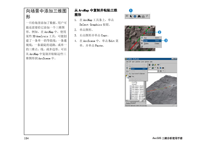
从ArcMap 中复制并粘贴三维图形1. 在ArcMap 工具条上,单击Select Graphics 按钮。
2. 单击图形。
3. 右击图形并单击Copy。
4. 在ArcScene 中,单击Edit 菜单,并单击Paste。
A RC GIS 三维分析使用手册184要素数据与三维显示用户可能想以透视视图可视化要素数据,以及表面数据。
在表达离散对象,而不是连续现象时,要素数据不同于表面数据。
一般来说,要素数据拥有一个(几何)形状和属性。
典型的要素几何图形有点、线和多边形。
点要素可能表示山峰,电话线杆,或水井位置。
线要素可能表示公路、河流或者脊岭。
多边形要素可能表示建筑物,湖泊,或行政区域。
要素的属性可以存储代表要素高程或高度的值。
某些GIS 要素以要素几何图形本身来存储高程值;例如,PointZ要素是以一套x,y,z坐标来存储。
在三维场景中,可以使用要素的几何图形或属性的Z值来显示要素。
以建筑物基底按高度拉伸的效果图有时候,要素缺少高程或高度值。
在三维场景中,通过叠加(draping)或拉伸(extruding)还可以查看这些要素。
如果有该区域的表面模型,可以使用模型中的值作为要素的Z值。
这叫做叠加要素。
也可以使用这一技术来三维可视化影像数据。
如果想要显示三维的建筑物要素,可以使用属性如建筑物高度或楼层数来突出显示它们。
也可以基于任意值来突出要素。
有时候,用户想要基于某一属性Z值而不是高度值在场景中查看二维要素。
例如,可能创建一个场景,这一场景显示基于人口值将城市突出成柱状。
美国城市按1990年人口数量拉伸显示的效果图三维可视化185查看图层的基表面高度1. 在ArcScene或ArcCatalog中,右击图层并单击Properties。
2. 单击Base Heights选项卡。
该图层没有基表面高度。
A RC GIS三维分析使用手册186通过属性设置基表面高度1. 右击图层并单击Properties。
ArcGIS三维分析使用指南中文高清版part1

什么是表面和表面模型? 78 使用点集创建栅格数据表面 80 栅格表面插值 89 克里格插值法 93 保存所有栅格到指定位置 96 设置分析掩膜 97 设置分析结果的坐标系统 98 设置输出范围 99 设置输出栅格单元尺寸 100 使用矢量数据创建TIN表面 101 创建TIN 103 使用栅格数据创建TIN表面 105 使用TIN创建栅格 106
在另一个浏览器中从其它角度浏览场景
用户可以改变三维图层的属性,应用图案阴影或者透明度; 也可以改变一个三维场景的属性,
栅格数据和矢量数据的三维视景
ArcScene的用途
ArcScene提供了可以查看具有多个图层的三维数据、数据可 视化、创建表面并分析表面的接口。
数据可视化
三维分析允许用户在表面上叠加影像或矢量数据,并从表面 上提取矢量要素。用户可以通过不同的浏览器从多个角度浏 览一个场景。
目录
ArcGIS三维分析使用手册 1
第一章 ArcGIS三维分析简介 3
三维分析的用途 5 学习三维分析的技巧 8
第二章 快速入门教程 9
复制教程数据 10 练习1:在地形表面上叠加影像 12 练习2:污染物在蓄水层中的可视化 22 练习3:土壤污染及甲状腺癌发病率的可视化 27 练习4:创建TIN表示地形 37 练习5:在ArcScene中操作动画 51 练习6:ArcGlobe基础 58 练习7:ArcGlobe图层分类 68
ArcMap中在栅格上创建的三维线图形以及这条线对应的剖 面图。
面z值数字化三维要素和图形的工具,以及一个沿三维线创
建剖面图(一定范围内的高程变化)的工具。
三维预览;识别要素、栅格单元以及TIN三角形。
ArcGIS 三维分析简介
ArcGIS3D学习指南
ArcGIS 3D学习指南目录一、3D分析功能简介二、创建表面模型三、表面分析四、三维可视化一、3D分析功能简介与3D分析功能有关的常用模块有:ArcSceneArcMap, ArcCatalog,其基本功能如下:1、A rcScene的功能:浏览三维数据、创建衣面、进行农面分析等。
2、ArcMap的功能:浏览三维数据、创建农面、进行衣面分析、在农面上寻找视线瞄准线、三个数字化三维要素工具与使用农面Z值图形工具、沿三维线创建剖面图的工具等。
3、ArcCatalog的功能:创建GIS数据图层并定义三维视图的-些展本属性、预览A reScene中场景等。
二、创建表面模型1、栅格衣面插值ArcGIS中支持的栅格农面插值有四种:反距离加权插值法、样条插值法、克里格插值法和自然领域插值法。
打开方式如图1所示:图1常用的栅格表而插值方法打开示例(1)反距离加权插值法如图1所示,单击Inverse Distance Weighted可打开反距离加权插值法(如下图所示),按照对话框提示可进行操作。
需要说明的是:Power指反距离加权法中距离的指数,指数越小农而越光滑,常用范围为O.5~3; Search radius type有两个选项,其中Variable <!<示可变半径反距离加权插值法,Fixed农示固定半径反距离加权插值法:在Output Raster中,选择你要保存的位置,否则容易丢失。
2)样条插值法如图1所示,单击Spline可打开样条插值法(如下图所示),可按照对话框提示进行操作。
需妥说明的是:在Spline type有两个选择,其中Tension衣示张力样条插值法,Regularized衣示规则样条插值法。
其它同上。
(3)克里格插值法如图1所示,单击Kriging可打开克里格插值法(如下图所示),按照对话框捉示可进行操作。
需要说明的是:Krging method衣示克立格类型,有普通克立格和泛克立格两种;从Semivariogram model 中,选择所需的模型,常用的有球而模型、指数模型等:Search radius type有两个选项,其中Variable 衣示可变半径克里格插值法,Fixed衣示固定半径克里格插值法。
- 1、下载文档前请自行甄别文档内容的完整性,平台不提供额外的编辑、内容补充、找答案等附加服务。
- 2、"仅部分预览"的文档,不可在线预览部分如存在完整性等问题,可反馈申请退款(可完整预览的文档不适用该条件!)。
- 3、如文档侵犯您的权益,请联系客服反馈,我们会尽快为您处理(人工客服工作时间:9:00-18:30)。
在ArcGIS中,三维可视化的主要功能有:创建三 维场景、向场景中添加图层与图形、定义图层的 三维属性、定义场景的属性、识别和选择要素、 管理场景浏览器、输出场景、打映场景等。下面 分别具体说明: 一、准备材料 1、 三波段合成的geotif影像数据 2、与影像坐标配套的DEM数据 3、如果有其他矢量元素,转为shape格式 4、arcgis软件(好像需要desktop版本,安装时选 择安装arcscene模块)
(4) 单击确定(如图标4所示)!
四、三维视图操作 鼠标右键上下移动为放大缩小,鼠标左 键为改变角度,鼠标中间按住拖动为移动场 景。在下图中,可调节影像的亮度与对比度。
视图质量设置
将此参数调高,否 则输出图很模糊
五、三维场景输出 方法一、见下图。
在弹出窗口中设置几个参数,用来控制输出图片的 大小。
设置这两处地方的参数, 以控制输出文件大小。经 多次实验,貌似ห้องสมุดไป่ตู้辨率最 大 只 能 600 , scene 最 大 只 能6000(实验版本:9.3)
方法二、 设置好参数之后,可以采用pdf打印输出。 输出时,设置纸张为较大尺寸,如A0等以上, 分辨率设置低一些,如150以下,这样可避免 出现白线条。 经过不成熟的摸索,认为白线条主要与影像 文件大小有关,应该避免让影像文件超过 200M
(1) 右击图层,在弹出的对话框中,选择 Base Heights(如图标1所示); (2) 单击Obtain heights for layerfrom suface (如图标2所示),选择您要添加的图层; (3) 如果两个图层的单位不一致,则要改变 Z Unit Conversion(如图标3所示),同时, 该系数也是用于高程放大因子;
六、三维路径飞行 1、调出如右图菜单
二、启动arcscene
三、创建三维场景: 1、创建新场景,又称为添加数据。在 ArcScene中,直接单击标准工具上的 图表 即可。 2、定义图层的Z值 一般有三种方法可以用来定义图层的Z 值,即:使用属性设置图层的基准高程;通 过在表面上添加新要素;突出要素。最常用 的是通过在表面上添加新要素,其步骤如下:
