W75AP
WNDAP360 Wi-Fi Access Point 安装和配置指南说明书
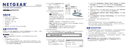
安装指南b. 将以太网线从WNDAP360连接到计算机上(图中的A 点)。
c.将网线的另一端牢固地插入WNDAP360的以太网端口(图中的B点)。
d.将电源适配器连接到WNDAP360上,并验证以下各项:•电源。
WNDAP360通电之后,电源指示灯会闪烁。
启动完成后,电源指示灯会长亮(保持亮绿灯)。
如果 30 秒后电源指示灯不亮或仍在闪烁,请检查相关连接,并查看电源插座是否由某个墙壁开关控制并已关闭。
•ACTIVE。
有网络流量时,ACTIVE LED 指示灯会闪烁。
•LAN。
LAN LED 指示灯指示 LAN 速度:绿色代表 1000 Mbps,琥珀色代表 100Mbps,熄灭则代表 10Mbps。
• 2.4G Hz (WLAN)。
此 LED 指示2.4GHz频段的无线流量。
• 5 G Hz (WLAN)。
此 LED 指示 5GHz频段的无线流量。
2.配置 LAN 和无线访问a.从计算机配置WNDAP360以太网端口以访问 LAN。
打开浏览器并在地址栏中输入以下网址来连接WNDAP360:http://192.168.0.100。
b.此时显示登录窗口。
在提示时,输入用户名admin和密码password,两者都为小写字母。
此时显示WNDAP360用户界面。
NETGEAR 线缆ABWNDAP360以太网端口c.从菜单中选择Configuration > System > Basic > General。
填写AccessPoint Name字段,并从下拉列表中选择操作所属的Country/Region。
d.从菜单中选择Configuration > IP > IP Settings,然后针对您的网络配置 IP设置。
e.如果您使用 DHCP,请在 DHCP 服务器上预留 IP 地址(根据WNDAP360的 MAC 地址)。
然后,您可以使用该地址登录WNDAP360。
f.选择Configuration > Wireless > Basic > Wireless Settings,并选中TurnRadio On设置。
Part-V-NETGEAR-WC7520无线控制器配置操课件

•28
WC7520配置
无线策略配置
•Part-V-NETGEAR-WC7520无线控制器配置操
•29
WC7520配置
基本属性配置
1. 在Configuration > Wireless > Basic > Channel Allocation中,将 Automatic Channel allocation选中enable;关闭Prevent Channel Change During的选项;关闭Schedule Channel Allocation的选项:
•Part-V-NETGEAR-WC7520无线控制器配置操
•21
WC7520配置
WC7520的基本配置 AP与WC7520的关联
WC7520会立即搜索网络中可管理的AP并显示在列表中
•Part-V-NETGEAR-WC7520无线控制器配置操
•22
WC7520配置
WC7520的基本配置
AP与WC7520的关联
•24
WC7520配置
WC7520的基本配置 AP与WC7520的关联
•Part-V-NETGEAR-WC7520无线控制器配置操
•25
WC7520配置
WC7520的基本配置 AP与WC7520的关联 4. 当AP的状态Status显示Connected的时候,那么AP就已经成功的关 联到WC7520。
•Part-V-NETGEAR-WC7520无线控制器配置操
•14
WC7520配置
检查WC7520的版本及版本升级
•Part-V-NETGEAR-WC7520无线控制器配置操
•15
WC7520配置
WC7520的基本配置
滚筒洗衣机使用与安装说明书-美诺

58 58 59 60 60 60 62 63 63
3
目录
______________________________________________________________________________________________________________________________________________
中断程序......................................................... 38 添加或取出衣物................................................... 39 衣物护理标签符号................................................. 40 洗涤剂........................................................... 41 正确的洗涤剂..................................................... 41 水质软化片....................................................... 41 配给量辅助用具................................................... 41 衣物柔顺剂或液态粉浆............................................. 41 Miele 建议洗涤产品................................................ 42 按照(EU)1015/2010 指令建议的洗涤剂............................. 43 清洁与保养....................................................... 清洁滚筒(除菌信息)............................................. 外壳与面板....................................................... 清洗............................................................. 清洁进水口过滤器................................................. 45 45 45 45 47
GSK980TDb 车床CNC使用手册(2010年3月第2版)--2010-03-23定稿

1.3.4 插补功能 ................................................................................................................................8
1.3.5 绝对坐标编程和相对坐标编程 ................................................................................................9
警 告!
z 在对本产品进行安装连接、编程和操作之前,必须详细阅读本产品手册 以及机床制造厂的使用说明书,严格按手册与说明书等的要求进行相关 的操作,否则可能导致产品、机床损坏,工件报废甚至人身伤害。
注 意!
z 本手册描述的产品功能、技术指标(如精度、速度等)仅针对本产品, 安装了本产品的数控机床,实际的功能配置和技术性能由机床制造厂的 设计决定,数控机床功能配置和技术指标以机床制造厂的使用说明书为 准;
一 篇
1.1 GSK980TDB 介绍..........................................................................................................................1
1.1.1 产品简介 ................................................................................................................................1 编
netgear wndap380r 安装指南说明书
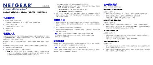
安装指南包装箱内容打开包装,验证是否有如下物品:•ProSafe® 双频 Wireless-N 接入点(支持 RFID)WNDAP380R•直通型 5 类以太网线•电源适配器和电缆(12V,1A)•墙壁安装工具•安装指南设置接入点本接入点无法单独使用。
它必须使用 ProSafe WC7520 无线控制器进行配置。
在继续 安装 WNDAP380R 前,请先熟读本手册中的内容,以及《ProSafe 20-AP 无线控制 器参考手册》中的接入点配置说明。
默认情况下,接入点上已启用 DHCP 寻址。
网络中必须配有 DHCP 服务器才能正常 运行。
如果要将接入点安装在比较高的位置,请先设置并测试设备来验证无线网络连接。
1.将无线接入点连接到您的网络。
2.将电源适配器连接到接入点,并验证下列事项。
•电源。
接入点第一次开机时,电源 LED 会闪烁。
几秒钟后,它会保持点亮(稳 定绿色光)。
如果 30 秒后电源 LED 不亮或仍然闪烁,请检查连接情况,并查 看电源插座是否由墙壁开关控制并且墙壁开关是否已关闭。
•ACTIVE。
有网络流量时,ACTIVE LED 指示灯会闪烁。
•LAN。
LAN LED 指示灯指示 LAN 的速度;亮绿色代表 1000 Mbps,亮琥珀色代表 100Mbps,熄灭时则代表 10Mbps。
• 2.4G Hz (WLAN)。
此 LED 指示灯指示 2.4 G Hz 通信。
• 5 G Hz (WLAN)。
此 LED 指示 5 G Hz 通信。
3.使用 PC 访问 WC7520,然后对 WC7520 执行发现过程。
WC7520 应在发现列表中显示接入点。
通过 PC 和 WC7520 无线 AP 控制器配置该接入点。
请参见《WC7520 参考手册》。
部署接入点1.断开接入点的连接,将它放在您要部署的位置上。
最佳的位置是架在墙壁等位置或安装于天花板上,最好是在您的无线覆盖区域的中心,并在所有移动设备的视线之内。
腾达Tenda便携式无线AP-路由器 W150M 用户手册

版权申明是深圳市吉祥腾达科技有限公司注册商标。
文中提及到的其它商标或商品名称均是他们所属公司的商标或注册商标。
本产品的所有部分,包括配件和软件,其版权属深圳市吉祥腾达科技有限公司所有,在未经过深圳市吉祥腾达科技有限公司许可的情况下,不得任意拷贝、抄袭、仿制或翻译成其它语言。
本手册中的所有图片和产品规格参数仅供参考,随着软件或硬件的升级会略有差异,如有变更,恕不另行通知,如需了解更多产品信息,请浏览我们的网站:目录第1章产品简介 (1)1.1产品规格 (2)1.2包装清单 (2)1.3面板指示灯及接口说明 (3)第2章产品硬件安装 (5)2.1硬件安装 (5)第3章工作模式介绍 (7)3.1无线接入点模式(AP模式) (7)3.2客户端+覆盖模式(C LIENT+AP模式) (8)3.3桥接+覆盖模式(WDS+AP模式) (8)3.4无线信号放大模式(WISP模式) (9)3.5无线路由器模式(W IRELESS R OUTER模式) (10)第4章如何登录到设备 (11)4.1正确设置您的计算机网络配置 (11)4.2登陆 (13)第5章工作模式设置 (14)5.1无线接入点模式设置向导 (14)5.2无线客户端+覆盖模式设置向导 (15)5.3无线桥接+覆盖模式设置向导 (18)5.4无线信号放大模式设置向导 (21)5.5无线路由器模式设置向导 (24)第6章高级设置 (30)6.1LAN设置 (30)6.2WAN设置 (31)6.3WAN口参数 (33)6.4MAC地址克隆 (33)6.5域名服务器 (34)第7章无线设置 (36)7.1基本设置 (36)7.2无线安全设置 (37)7.3高级设置 (40)7.4WPS设置 (41)7.5无线访问控制 (43)7.6连接状态 (44)第8章DHCP服务器 (45)8.1DHCP服务设置 (45)8.2DHCP列表与绑定 (46)第9章虚拟服务器 (47)9.1端口段映射 (47)9.2DMZ主机 (48)9.3UPNP设置 (49)第10章安全设置 (50)10.1客户端过滤 (50)10.2URL过滤 (51)10.3MAC地址过滤 (52)10.4防网络攻击 (54)10.5远程WEB管理 (54)10.6WAN口PING (55)第11章路由设置 (56)11.1路由表 (56)第12章系统工具 (57)12.1时间设置 (57)12.2DDNS (57)12.3备份/恢复设置 (59)12.4恢复出厂设置 (60)12.5软件升级 (61)12.6重启设备 (61)12.7修改登录密码 (62)12.8系统日志 (62)12.9退出登录 (63)附录一:如何将电脑的IP地址改成自动获取? (64)附录二:设备加密后如何设置,能让无线网卡成功连接到本设备? (67)附录三:名词解释 (69)附录四:常见问题解答 (71)第1章产品简介感谢您购买W150M便携式无线AP/路由器(以下简称设备)W150M是一款便携式无线AP/设备,W150M无线传输速率为150Mbps,它具有五种功能实现各种无线应用。
NETGEAR ProSAFE WC7500 企业级无线控制器数据表说明书
Deployed as an overlay on the existing wired network infrastructure, the NETGEAR ProSAFE WC7500 Premium Wireless Controller simplifies the network management by providing a single point of management for the entire wireless network. Easy to set up, the WC7500 Controller discovers all supported access points in the network, even across VLANs and subnets. Once identified, the access points are provisioned in minutes. The discovery process follows an efficient and fast protocol in Ufast™.
The NETGEAR ProSAFE WC7500 Wireless Controller manages the full line of NETGEAR ProSAFE Access Points, from entry level single band APs (WNAP210 and WNAP320), business class dual band APs (WNDAP350 and WNDAP360), high performance 3x3:450 Mbps per radio dual band concurrent APs (WNDAP660), to specialized in-wall mounted APs (WN370) and outdoor APs (WND930) to a full line of industry fastest 802.11 ac APs (WAC720 and WAC730) all with a single click of a mouse.
网件WNDAP350-C和WC7520产品
12V DC,1A电源适配器(各个国家采用定制电源插头)
LEDs
电源、测试、100/1000Mbps、Link/ACT、2.4GHz频段、5GHz频段
控制端口
1个标准的RS232C接口(DB-9 Male连接器)
天线连接器
2个反向的SMA天线连接器(Reverse SMA)
注:不建议搭配使用Prosafe天线ANT24O5、ANT2409或ANT24D18
网件WNDAP350-C和WC7520产品
产品参数
序号
产品名称
品牌
型号
产品描述
1
无线接入点
NETGEAR
WNDAP350-C
ProSafe WNDAP350-C 802.11A/B/G/N无线以太网接入点(AP),支持POE远程供电,桥接并提供业界领先的安全功能;配合WC7520无线控制器提供全新的802.11n的第三代智能无线控制器方案
卸下AP或者妥协FR环境下的监测警报
自我修复:自动调节邻近AP的功率以增加到填满覆盖损耗
负载平衡
AP的负载检测和过载预防
客户端重定向减轻邻近AP负载
快速漫游
通过VLAN和子网实现无缝快速漫游
包括802.lli pre-auth和快速漫游
快速漫游支持横跨L2,和L3为视频、音频、无线客户端传来的声音
服务质量(QoS)
2
无线控制器
NETGEAR
WC7520
ProSafe WC7520无线控制器,4个10/100/1000M端口,单台可管理50AP;支持IEEE802.11a/b/g/n协议;支持二层、三层漫游;最大支持3台堆叠(最大可支持150个AP);支持N+1冗余(N=<3)
IP-COM全系列产品对比表(手打)
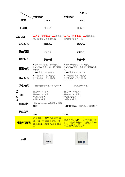
W10APW15AP150M150M建议5台建议5台办公室,酒店客房,KTV 等墙体多,需要稳定覆盖的区域办公室,酒店客房,KTV 等墙体多,需要稳定覆盖的区域面板式AP面板式AP1-2间房1-2间房胖瘦一体胖瘦一体1.集中软件管理(胖AP模式)2.M系列AC管理,无上限(限瘦AP模式)3.web管理(胖AP模式) 1.集中软件管理(胖AP模式)2.M系列AC管理,无上限(限瘦AP模式)3.web管理(胖AP模式)1.三层漫游(瘦AP模式)2.二层漫游(胖AP模式)1.三层漫游(瘦AP模式)2.二层漫游(胖AP模式)直流适配器供电,不支持POE 只支持POE供电接口按键接口百兆LAN口*1输入百兆LAN口*1输出电话口*1接入电话口*1接出百兆LAN口*1输入百兆LAN口*2输出电话口*1接入电话口*1接出(86*86*35mm)86盒设计,兼容75盒(86*86*35mm)86盒设计,兼容75盒50mW 50mW酒店客房,KTV,办公室等墙体较多,环境较为复杂,现场具有86底盒或75底盒的地方酒店客房,KTV,办公室等墙体较多,环境较为复杂,现场具有86底盒或75底盒的地方带机量适用场合安装方式管理方式漫游方式胖瘦方式供电方式覆盖范围外观规格外观速率天线功率推荐适用环境入墙式W30APF130AP300M300M建议8台规范:满载7台,简单手机上网10-15办公室,酒店客房,KTV 等墙体多,需要稳定覆盖的区域酒店客房区,KTV,餐厅,商场,会议室等空旷区域面板式AP吸顶式AP室内15-20m,3-5间房室内20米,4个房间胖瘦一体胖瘦一体出厂瘦AP模式,可切换为胖AP 1.集中软件管理(胖AP模式)2.M系列AC管理,无上限(限瘦AP模式)3.web管理(胖AP模式) 1.瘦AP模式只支持CW500控制器管理2.胖Ap web管理1.三层漫游(瘦AP模式)2.二层漫游(胖AP模式)1.三层漫游(瘦AP模式)2.二层漫游(胖AP模式)只支持POE供电1.直流适配器供电2.POE供电百兆LAN口*1 输入百兆LAN口*1 输出USB供电输出端口千兆LAN口*1板载预留TTL,JTAG调接口(86*86*35mm)86盒设计,兼容75盒直径15CM100mW90mW酒店客房,KTV,办公室等墙体较多,环境较为复杂,现场具有86底盒或75底盒的地方酒店自助餐厅、酒店大堂、会议室、商场、KTV、办公楼过道等空旷区域,需要大范围覆盖的室内区域W40APW45APW65AP450M300M450M规范:满载7台,简单手机上网10-15规范:满载15台,手机20-25台规范:满载25台,手机45台以内酒店客房区,KTV,餐厅,商场,会议室等空旷区域酒店客房区,KTV,餐厅,商场,会议室等空旷区域酒店客房区,KTV,餐厅,商场,会议室等空旷区域吸顶式AP吸顶式AP吸顶式AP室内20米,8个房间室内20m-30m,8-12个房间室内40m-50m,10-16个房间胖瘦一体胖瘦一体胖瘦一体1.集中软件管理(胖AP模式)2.M系列AC管理,无上限(限瘦AP模式)3.web管理(胖AP模式) 1.集中软件管理(胖AP模式)2.M系列AC管理,无上限(限瘦AP模式)3.web管理(胖AP模式) 1.集中软件管理(胖AP模式)2.M系列AC管理,无上限(限瘦AP 模式)3.web管理(胖AP模式)1.三层漫游(瘦AP模式)2.二层漫游(胖AP模式) 1.三层漫游(瘦AP模式)2.二层漫游(胖AP模式) 1.三层漫游(瘦AP模式)2.二层漫游(胖AP模式)1.直流适配器供电2.POE供电1.直流适配器供电2.POE供电只支持POE供电千兆LAN口*1板载预留TTL,JTAG调接口千兆LAN口*1板载预留TTL,JTAG调接口千兆LAN口*1 输入千兆LAN口*1 输出板载预留TTL,JTAG调接口V2.0版增加了无线开关按钮直径15CM直径15CM20*20*3cm100mW200mw(11b模式最高可达400mW)400mW(b/g/n模式)酒店自助餐厅、酒店大堂、会议室、商场、KTV、办公楼过道等空旷区域,需要大范围覆盖的室内区域酒店自助餐厅、酒店大堂、会议室、商场、KTV、办公楼过道等空旷区域,需要大范围覆盖的室内区域酒店自助餐厅、酒店大堂、会议室、商场、KTV、办公楼过道等空旷区域,需要大范围覆盖的室内区域吸顶式W75APW85AP900M(2.4G为450;5G为450M)1750M(2.4G为450;5G为1350M)规范:双频满载60以内,手机40-50规范:双频满载45以内,手机40-50酒店客房区,KTV,餐厅,商场,会议室等空旷区域酒店客房区,KTV,餐厅,商场,会议室等空旷区域吸顶式AP吸顶式AP室内40m-50m,10-16个房间室内40m-50m,10-16个房间胖瘦一体胖瘦一体1.集中软件管理(胖AP模式)2.M系列AC管理,无上限(限瘦AP模式)3.web管理(胖AP模式) 1.集中软件管理(胖AP模式)2.M系列AC管理,无上限(限瘦AP模式)3.web管理(胖AP模式)1.三层漫游(瘦AP模式)2.二层漫游(胖AP模式)1.三层漫游(瘦AP模式)2.二层漫游(胖AP模式)只支持POE供电只支持POE供电千兆LAN口*1 输入千兆LAN口*2 输出板载预留TTL,JTAG调接口千兆LAN口*1 输入千兆LAN口*1 输出板载预留TTL,JTAG调接口20*20*3cm直径21,高12.8cm400mW(2.4G),(b/g模式可达400mW,n模式为200mW);100mW(5G)400mW(2.4G),(11B模式可达400mW,n模式为200mW);100mW(5G)酒店自助餐厅、酒店大堂、会议室、商场、KTV、办公楼过道等空旷区域,需要大范围覆盖的室内区域酒店自助餐厅、酒店大堂、会议室、商场、KTV、办公楼过道等空旷区域,需要高带机量的区域双频吸顶式P130APP131AP300M没设计最高连接数,接入信息根据实际连接带宽计算。
WC7520 Wireless Access Point 用户指南说明书
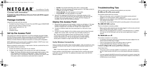
Installation Guide• ACTIVE . The ACTIVE LED blinks when there is network traffic.• LAN. The LAN LED indicates LAN speeds; green for 1000 Mbps, amber for 100Mbps, and no light for 10Mbps.• 2.4G Hz (WLAN). This LED indicates 2.4 G Hz traffic.• 5 G Hz (WLAN). This LED indicates 5 G Hz traffic.2. Use a PC to access the WC7520 and run a Discovery process on theWC7520. The WC7520 should show the access point in the discovery list. Configure the access point using a PC and the WC7520 Wireless AP Controller. See the WC7520 Reference Manual .Deploy the Access Point1. Disconnect the access point and position it where you will deploy it. The bestlocation is elevated such as wall or ceiling mounted, at the center of your wireless coverage area, and within line of sight of all mobile devices.2. Connect an Ethernet cable from the access point to a LAN port on yournetwork.3. Connect the power adapter to the wireless access point and plug the poweradapter into a power outlet. The Power and LAN LEDs should go on.Tip: The access point supports Power over Ethernet (PoE). If you have a switch that provides PoE, you do not need to use the power adapter to power the access point. This can be especially convenient when the access point is installed in a high location far from a power outlet.Verify Wireless ConnectivityUsing a computer with an 802.11b/g/n wireless adapter, verify connectivity by using a browser to connect to the Internet, or check for file and printer access on your network.Note: If you cannot connect, see Troubleshooting Tips in this guide.Proper operation of the RFID feature can be determined by reviewing the access point status using the WC7520. For additional information refer to the WC7520 Reference Manual.Troubleshooting TipsHere are some tips for correcting simple problems you may have.No LEDs are lit on the access point.The wireless access point has no power.• Make sure the power cord is connected to the wireless access point andplugged in to a working power outlet or power strip.• Make sure you are using the correct NETGEAR power adapter supplied withyour wireless access point.• If using PoE, ensure that the PoE switch is providing power to the access point.The LINK/ACT LED is not on.There is a hardware connection problem.• Make sure the cable connectors are securely plugged in to the access point andto the network device (hub, switch, or router).• Make sure the connected device is turned on. If the Ethernet link is a 10 Mbpslink, then the 10/100/1000 light is off, but the Link/Act light blinks if traffic is present.The WLAN LEDs are off.The wireless connection is not working.• If a Wireless LAN activity LED stays off, disconnect the power adapter from itspower source and then plug it in again.• Log in to the access point and verify that the radio is turned on.• Contact NETGEAR if the Wireless LAN LED remains off.I cannot configure the access point from a browser.Check these items:• The access point is correctly installed, it is powered on, and LAN connectionsare OK. Check that the LAN LED is on to verify that the Ethernet connection is OK.• If you are using the Net BIOS name of the access point to connect, ensure thatyour PC and the access point are on the same network segment or that there is a WINS server on your network.ProSafe® Dual Band Wireless-N Access Point with RFID support WNDAP380RPackage ContentsUnpack the box and verify the contents:• ProSafe® Dual Band Wireless-N Access Point with RFID support WNDAP380R • Straight through Category 5 Ethernet cable • Power adapter and cord (12V, 1A)• Wall mount kit • Installation GuideSet Up the Access PointThis access point cannot be used alone. It must be configured using the ProSafe WC7520 Wireless Controller. Before proceeding with the WNDAP380R installation, familiarize yourself with the contents of this manual and the ProSafe 20-APWireless Controller Reference Manual instructions on access point configuration. DHCP addressing on the access point is enabled by default. A DHCP server must be present in the network for proper operation.Before mounting the access point in a high location, first set up and test the unit to verify wireless network connectivity.1. Connect the wireless access point to your network.2. Connect the power adapter to the access point and verify the following:• Power. The Power LED blinks when the access point is first turned on. After a few seconds it should stay on (steady green). If after 30 seconds thePower LED is off or is still blinking, check the connections and check to see if the power outlet is controlled by a wall switch that is turned off.December 2011This symbol was placed in accordance with the European Union Directive 2002/96 on the Waste Electrical and Electronic Equipment (the WEEE Directive). If disposed of within the European Union, this product should be treated and recycled in accordance with the laws of your jurisdiction implementing the WEEE Directive.©2011 by NETGEAR, Inc. All rights reserved. NETGEAR, the NETGEAR logo, and ProSafe® are registered trademarks of NETGEAR, Inc. in the United States and/or other countries. Other brand and product names aretrademarks or registered trademarks of their respective holders. Information is subject to change without notice.I cannot access the Internet or the LAN with a wireless capable computer.There is a configuration problem. Check these items:• You might not have restarted the computer with the wireless adapter to haveTCP/IP changes take effect. Restart the computer.• The computer with the wireless adapter might not have the correct TCP/IPsettings to communicate with the network. Restart the computer and check that TCP/IP is set up correctly for that network. The usual setting for Windows on the Network Properties is set to “Obtain an IP address automatically.”• The wireless access point’s default values might not work with your network.Check the wireless access point default configuration against the configuration of other devices in your network.• For full instructions on changing the default values of the wireless access point,see the WC7520 Reference Manual .Statement of ConditionsIn the interest of improving internal design, operational function, and/operability, NETGEAR reserves the right to make changes to the product described in this document without notice. NETGEAR does not assume any liability that may occur due to the use or application of the product(s) or circuit layout(s) described herein.Technical SupportThank you for selecting NETGEAR products.After installing your device, locate the serial number on the label of your product and use it to register your product at /register . Registration is required before you can use our telephone support service. Registration via our web site is strongly recommended.Go to for product updates and Web support. ForWarranty and Regional Customer Support information, see the Resource CD that came with your product.For complete DoC please visit the NETGEAR EU Declarations of Conformity website at: /app/answers/detail/a_id/11621/。
WC7520无线控制器

ProSafe™无线控制器WC7520为中小型企业、学校和医院设计的安全可靠的可扩展的无线控制器网件ProSafe 20-AP无线控制器WC7520提供了一个高性能、多功能的无线局域网架构,以满足中小型企业、学校和医院等环境多达1500个以上用户的需求。
为了易于使用,WC7520无线控制器简化了无线网络的部署和管理,同时拥有最好的无线可靠性、覆盖面和性能。
WC7520无线控制器的可扩展性让企业拥有非常大的投资回报,企业用户可以根据需求变化选择相应的licenses,从而扩展其无线网络。
通过升级licensing,ProSafe 无线控制器不但能够扩展到支持50个接入点,而且能够支持新一代的IEEE 802.11n接入点。
对于大型的网络部署,WC7520控制器通过3个单位的堆叠,实现冗余的同时能够支持多达150个接入点。
为了适应往后更多应用的需要,WC7520控制器提供了集中式的无线管理,综合了无线的灵活性,强大高端的安全性能,丰富的管理应用如二层/三层的快速漫游、captive portal客人访问认证、支持Wi-Fi Voice。
最后,WC7520提供了企业级的接入和安全的无线局域网连接。
可升级的架构体系WC7520控制器能够支持IEEE 802.11a/b/g,通过升级WC75NL license可支持IEEE 802.11n。
WC7520控制器本身可以支持20个接入点,升级一次WC7510L licenses,可以增加10个接入点,最多可以支持50个接入点。
可以实现3个控制器的堆叠,1组堆叠的WC7520控制器可以通过一个接口连接150个接入点。
更重要的是,WC7520提供了可靠的不间断的令人放心的冗余技术。
集中管理相对目前的有线网络的部署架构而言,NETGEAR的ProSafe 20-AP 无线控制器能够通过一个单一端口管理整个无线网络,从而简化了网络管理。
WC7520控制器安装非常简单,即使是跨越VLAN和子网,它也能够发现网络中可以支持的接入点。
ProSAFE 无线控制器 Model WC7500 和 Model WC7600 安装指南说明书
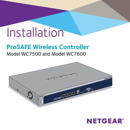
Installation ProSAFE Wireless ControllerModel WC7500 and Model WC7600Hardware OverviewBefore you install your wireless controller, familiarize yourself with its LEDs, buttons, and ports.ResetportEthernet ports Power, Status, Fan, Stack Master SD slot Digital access portsPackage Contents• Wireless controller• Ethernet cable• One or more power cords (varies by region)• Rack-mounting hardware• Installation guide (this document)Connect PowerWARNING: DO NOT place equipment in tight spaces or in drawers. Be sure that your equipment is surrounded by at least 5 cm (2 inches) of air space. Before deploying the wireless controller, we recommend that you set up and test the device.1. Plug the wireless controller into a power outlet.2. Check the LEDs on the wireless controller.The following table describes the behavior of the wireless controller LEDs.Wireless Controller LEDsConfigure the Wireless Controller1. Record your computer’s TCP/IP configuration settings, and thenconfigure the computer with a static IP address of 192.168.0.210and with 255.255.255.0 as the subnet mask.Note: If you are unsure how to do this, visit and search for Static IP address on computer.2. Connect one end of the supplied Ethernet cable to the Ethernet porton your computer and the other end to the Ethernet port on the front panel of the wireless controller.Note: All four Ethernet ports provide equal performance and arebonded together to form Linux active-backup mode.3. Open a web browser and enter http://192.168.0.250.4. Enter the password.The default password is password.Note: The first time you log in, you must change the password.You cannot change the admin user name, but you can create a newadministrative account with a customized user name.5. Click the Login button.6. To set up the wireless controller name and select the country in whichthe wireless controller is used, select Configuration > System >General.7. To choose the time zone and optionally configure NTP settings, selectConfiguration > System > Time.8. To configure the wireless controller IP settings, select Configuration> System > IP/VLAN.When you click the Apply button to save your settings, yourconnection to the wireless controller is terminated because youchanged its IP address.9. Reconfigure your computer with an IP address and subnet mask thatare in the same IP subnet as the wireless controller. Use the new IPaddress of the wireless controller to log in again.10. Select Configuration > System > DHCP Server and specify theDHCP server settings.The Discovery Wizard (see Discover Access Points on page 8)requires a DHCP server to discover the access points.If your network already includes a DHCP server, disable the DHCP server on the wireless controller. Otherwise, configure the DHCP settings for the DHCP server on the wireless controller.11. To configure the WLAN settings, select Configuration > Profile.Basic settings are suitable for a small WLAN. Advanced settings are suitable for a large WLAN with profile groups.For information about wireless controller configuration, including profile groups, see the reference manual.Deploy the Wireless Controller1. Disconnect the power cord from the wireless controller.2. Disconnect the wireless controller from the computer and place itwhere you intend to deploy it.3. Connect one end of an Ethernet cable to a LAN port on a router orswitch in your network and the other end to the Ethernet port on the front panel of the wireless controller.4. Reconnect the power cord from the wireless controller to an ACpower outlet.The LEDs light as described in Wireless Controller LEDs on page 4. Discover Access PointsThe Discovery Wizard can discover access points over a Layer 2 or Layer 3 network. The following general guidelines apply to the discovery process (for specific Layer 3 guidelines, see the reference manual):• The wireless controller can discover access points that are still in their factory default state and access points that are already deployed in a standalone configuration.Both access points in the factory default state and deployedstandalone access points run standalone firmware.• Access points in the factory default state that are in the same Layer 2 network and are assigned the same IP address can be discovered.In the factory default state, AP dynamic IP configuration is disabled by default. After discovering an access point, you can either enable it from the wireless controller or leave it in its default state. If youenable dynamic IP configuration on the access points, firmwareupgrades on access points occur in parallel. Otherwise, firmwareupgrades on access points happens sequentially, which takes longer.• Specifying an internal DHCP server on the wireless controller automatically enables DHCP option 43 (vendor-specific information) with the IP address of the wireless controller.When an external DHCP server is used, Option 43 is not required if the access points are in the same Layer 2 network as the wirelesscontroller. If the access points are not in the same L2 network, then Option 43 with the wireless controller IP must be configured on the external server.¾To discover access points and add them to the Managed AP List:1. Access the wireless controller at the network IP address that youconfigured (see Configure the Wireless Controller on page 5).2. Select Access Point > Discovery > Discovery Wizard.3. Follow the steps onscreen to discover the access points and reviewthe discovery results.4. Select Access Point > Discovery > Managed AP List. Add theaccess points that you want to be managed by the wireless controller to the Managed AP List.While the access points are being converted from standalone mode to managed mode, the following occurs:• The wireless controller pushes management firmware onto the access points.• The access points become DHCP clients and receive an IP address from either the DHCP server in your network or the DHCP serveron the wireless controller.• The profiles that you have configured on the wireless controller are pushed onto the access points.Note: For extensive information about the Discovery Wizard and the discovery process, see the reference manual.Troubleshooting TipsYou cannot access the wireless controller at its default IP address (192.168.0.250). Do the following:• Confirm that the computer is connected to the wireless controller.• You might not have restarted the computer with the wireless controller to have TCP/IP changes take effect. Restart the computer.• The computer might be set to enable NetBIOS over TCP/IP.• Check to see that TCP/IP is set to use the same subnet as the wireless controller. By default, the wireless controller uses a subnet mask of255.255.255.0. (The default TCP/IP setting for Windows is to obtain an IP address automatically.) Restart the computer.After initial configuration, you cannot access the wireless controller at its network address. Do the following:• Use the ping command to verify the connection.• Verify that the computer and wireless controller are on the same VLAN.• After initial configuration, make sure that the wireless controller settings are correct and compatible with your network.11January 2016NETGEAR, Inc.350 East Plumeria DriveSan Jose, CA 95134, USASupportThank you for purchasing this NETGEAR product. You can visit /support to register your product, get help, access the latest downloads and user manuals, and join our community. We recommend that you use only official NETGEAR support resources.Trademarks© NETGEAR, Inc., NETGEAR and the NETGEAR Logo are trademarks of NETGEAR, Inc. Any non-NETGEAR trademarks are used for reference purposes only.ComplianceFor the current EU Declaration of Conformity, visit /app/answers/detail/a_id/11621/.For regulatory compliance information, visit /about/regulatory/.See the regulatory compliance document before connecting the power supply.。
NETGEAR ProSafe 20-AP Wireless Controller WC7520 中
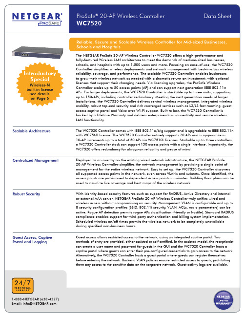
Introductory SpecialWC7520+1 x WC75NL+3 x WC7510LGSM7352S(stack)STM600SRX5308PoEPoE80 x WNDAP35040 x WNAP210WC7520 +1 x WC75NL +3 x WC7510LWC7520+1 x WC75NLWC7520+1 x WC75NL+3 x WC7510L(stack)(redundant) InternetExample of Wireless-N configuration with 120 access points (AP) and one redundant controller.WC7510L Adds 10 APWC7510LAdds 10 APWC7510LAdds 10 APSupports 20 APAdds Wireless-N supportWC7510L Adds 10 APWC7510LAdds 10 APWC7510LAdds 10 APWC7520 Supports 20 APWC7510LAdds 10 APWC7510LAdds 10 APWC7510LAdds 10 APWC7520Supports 20 APWC7510LAdds 10 APWC7510LAdds 10 APWC7510LAdds 10 APWC7520Supports 20 APAdds Wireless-N support Adds Wireless-N support Adds Wireless-N supportCONFIGURATION EXAMPLES - WIRELESS A/B/G DEPLOYMENTIP AND VLANS CONFIGURATIONDHCP Server/Relay• Integrated DHCP server• Multiple DHCP server/pool can be added for different VLANs (up to 64)VLANs for the Wireless Controller One management VLAN (confi gurable VLAN ID)VLANs Access Points / Multiple SSIDs64 VLANsVLANs Deployment The Wireless Controller must have IP connectivity with the access points through the management VLAN. If the Controller and theAPs are on different management VLANs, external VLAN routing must allow IP connectivity between the Controller and the APs. RF PLANNING AND MONITORINGIntegrated Deployment Planning• Hierarchical view of the network: Floor maps upload and fl oor maps dimensions input• Automated RF planning algorithm: Computed number of APs required to cover a fl oor plan• Theorical cloud coverage indicated for each AP for positionning assistance on the fl oor planRF Monitoring• Coverage computing per fl oor plan• Alert for any detected coverage holes with mitigation options with neighboring APs• Rogue AP/blacklisted clients triangulationRF MANAGEMENTAutomatic Channel Allocation• Channel automatic distribution to reduce interference• Auto-channel allocation takes into consideration the AP location, interferences, and neighborhood maps for each AP• Modifi able list of corporate channels to be used• Scheduled mode for auto-channel allocation• Automatic mode available in case of high level of interferenceAutomatic Power Control• Optimum transmit power determination based on coverage requirements• Automatic power control mode available• Neighborhood scan of RF environment to minimize neighboring AP interference and leakage across fl oorsCoverage Hole Detection• Automatic mode• Down APs or compromised RF environment detection with alerts• Self healing: Automatic neighboring AP power increase to fi ll in for coverage lossesLoad Balancing• AP load monitoring and overload prevention• Client redirection to lightly loaded neighboring APsFast Roaming• Seamless rapid mobility across VLAN and subnets• Includes 802.11i pre-auth and fast roaming• Fast roaming support accross L2, and L3 for video, audio and voice over wireless clientQUALITY OF SERVICEWMM Quality of Service WMM (802.11e) prioritizes traffi c for both upstream traffi c from the stations to the access points (station EDCA parameters) anddownstream traffi c from the access points to the client stations (AP EDCA parameters)WMM Queues in Decreasing Order of Priority • Voice: The highest priority queue with minimum delay, which makes it ideal for applications like VoIP and streaming media• Video: The second highest priority queue with low delay is given to this queue. Video applications are routed to this queue• Best effort: The medium priority queue with medium delay is given to this queue. Most standard IP application will use this queue • Background: Low priority queue with high throughput. Applications, such as FTP, which are not time-sensitive but require high throughput can use this queueWMM Power Save Option WMM power save helps conserve battery power in small devices such as phones, laptops, PDAs, and audio players using IEEE®802.11e mechanismsRate Limiting• Rate limit per SSID set as a percentage of total available bandwidthWIRELESS SECURITYClient Authentication Protocols• Open, WEP, WPA/WPA2-PSK• 802.11i/WPA/WPA2 Enterprise with standard interface to external AAA/RADIUS ServerDistinct AAA Server per SSID YesRADIUS Accounting Protocol Per Client tracking for:• Bytes Tx/Rx• Connect/disconnect timeLDAP-based Authentication• Standard interface to external LDAP server/Microsoft® Active Directory ServerIntegrated AAA Server Local database authentication based on WC7520 internal RADIUS ServerGuest Access• Integrated captive portal available for client authentication in a security profi le• Password based authentifi cation mode: Local user store available, receptionist assigned user name/password• Open authentication mode: Guest auto registration with email address• Extraction of logs of guest activityCaptive Portal Confi gurable portal page, including image fi lesRogue Access Points• Rogue AP defi nition: AP with radio SSID oberved by any of the managed APs and seen transmitting on same L2 wired network• Detection and mapping of up to 512 rogue APsWIRELESS NETWORK MONITORINGMonitoring Summary Summary of managed access points status, rogue access points detected, wireless stations connected, Wireless Controllerinformation and wireless network usageManaged Access Points AP status for the managed access points and details that includes confi guration settings, current wireless settings, current clientsand detailed traffi c statisticsRogue Access Points• Rogue access points reported• Rogue access points in same channel• Rogue access points in interfering channelsWireless Clients• Clients statistics and details per AP, per SSID, per fl oor, per location• Blacklisted clients, roaming clientsWireless Network Usage Network usage statistics display plots of average received/transmitted network traffi c per managed access point. Three differentplots show Ethernet, Wireless 802.11 b/bg/ng and 802.11 a/na mode traffi c separatelyHeat Maps• Live coverage and visualization heat maps• Location visualization and device trackingDHCP Leases DHCP details for wireless clientsMANAGEMENTManagement Interface HTTP, SNMP v1/v2c, telnet, Secure Shell (SSH)Logging and Reporting• If available syslog server on the network, the Wireless Controller can send all logs. Logs are also available on the GUI and readyto download (log export fi le)• Email alerts for events as per confi guration to mutiple email addressesDiagnostics Managed access points pingMaintenance Save/restore confi guration, restore to factory defaults, admin password change, add user (read-only), fi rmware upgrade via Webbrowser for the Wireless Controller and the managed access pointsDual Boot Image SupportedSNMP SNMP v1/v2cIEEE AND IETF RFC STANDARDSWired IEEE Standards• IEEE 802.3 10BASE-T, IEEE 802.3u 100BASE-TX, IEEE 802.3ab 1000BASE-T• IEEE 802.1Q VLAN taggingWired IEEE Standards• IEEE 802.11a, 802.11b, 802.11g, 802.11n• WMM (from 802.11e)RFC - System Facilities• RFC 1001 Protocol standard for a NetBIOS service on a TCP/UDP transport: Concepts and methods• RFC 1002 Protocol standard for a NetBIOS service on a TCP/UDP transport: Detailed specifi cations• RFC 1155 Management information for TCP/IP networks• RFC 1305 Network Time Protocol (Version 3) Specifi cation, Implementation and Analysis• RFC 2131 DHCP• RFC 3768 Virtual Router Redundancy Protocol (VRRP)• RFC 768 UDP• RFC 791 IP• RFC 792 ICMP• RFC 793 TCP• RFC 826 ARPRFC - Security and AAA • WPA-PSK, WPA2-PSK• RFC 1321 MD5 Message – Digest Algorithm• RFC 1851 Triple DES Algorithm• RFC 2246 TLS Protocol Version 1.0• RFC 2404 HMAC-SHA-1-96• RFC 3280 Internet X.509 PKI Certifi cate and CRL certifi cate• RFC 3377 Lightweight Directory Access Protocol (v3): Technical Specifi cation• RFC 3565 Use of the Advanced Encryption Standard (AES) Encryption Algorithm in Cryptographic Message Syntax• RFC 4346 TLS Protocol version 1.1IEEE AND IETF RFC STANDARDSRFC - Management• SNMP v1, v2c• RFC 364 syslog• RFC 854 telnet• RFC 1156 MIB• RFC 1157 SNMP• RFC 1213 MIB II• RFC 1350 TFTP• RFC 2616 HTTP• RFC 3164 The BSD Syslog Protocol• Enterprise private MIBs350 E. Plumeria DriveSan Jose, CA 95134-19111-888-NETGEAR (638-4327) E-mail: info@ © 2010 NETGEAR, Inc. NETGEAR, the NETGEAR Logo, NETGEAR Digital Entertainer Logo, Connect with Innovation, FrontView, IntelliFi, PowerShift, ProSafe, ProSecure, RAIDar, RAIDiator, RangeMax, ReadyNAS, Smart Wizard, X-RAID, and X-RAID2, are trademarks and/or registered trademarks of NETGEAR, Inc. and/or subsidiaries in the United States and/or other countries. Mac and the Mac logo are trademarks of Apple Inc., registered in the U.S. and other countries. Other brand names mentioned herein are for identification purposes only and may be trademarks of their respective holder(s). Information is subject to change without notice. All rights reserved.*Free basic installation support provided for 90 days from date of purchase. Advanced product features and configurations are not included in free basic installation support; optional premium support available.D-WC7520-3HARDWAREGigabit RJ45 Ports LAN Switch 4-port 10/100/1000Flash Memory/RAM8 MB + 2 GB CF/1 GB DDR2USB Port 1 port for USB storage• More fl oor heat maps• Extended statistics historyMajor Regulatory Compliance FCC Class A, CE, WEEE, RoHSStorage and Operating Temperatures Operating temperature 0°-45° C (32°-113° F),Storage temperature -20°-70° C (-4°-158° F)Humidity Operation 90% Maximum Relative, Storage 95% Maximum RelativeElectrical Specifi cations100-240V, AC/50-60Hz, Universal Input, DC 5V/8A (internal power supply)Dimensions (W x H x D) cm26.1 x 4.3 x 44Dimensions (W x H x D) in10.3 x 1.7 x 17.3Weight kb/lb 2.912/6.4System Requirements Internet Explorer® 5.0 or higher or Mozilla Firefox® 1.0 or higherPackage Contents ProSafe 20-AP Wireless Controller (WC7520), Ethernet cable, power cord, installation guide, resource CD Warranty ProSafe Lifetime WarrantyORDERING INFORMATION - CONTROLLERNorth America WC7520-100NAS Promotional version including built-in Wireless-N License*Europe WC7520-100EUS Promotional version including built-in Wireless-N License*Asia WC7520-100AUS Promotional version including built-in Wireless-N License* ORDERING INFORMATION - LICENSESIncremental 10-AP License Upgrade WC7510L-10000SWireless-N License Upgrade WC75NL-10000SPROSUPPORT SERVICE PACKSOnCall 24x7, Category 3PMB0333XPressHW, Category 3PRR0333-100* NETGEAR reserves the right to terminate the built-in Wireless-N promotion anytime without prior notice.。
NETGEAR ProSAFE WC7520 Wireless Controller 配置办公室和客
NETGEAR® ProSAFE® WC7520Wireless ControllerConfi guring Offi ce and Guest SSIDs Using a Layer 3 Switch on Separate Layer 3 SubnetsAPPLICATION NOTESINTRODUCTIONBusiness environments are dynamic in nature, with many diff erent types of users, each with a wide range of networking needs. Employees and contractors require Internet connectivity and access to printers, fi les, and other shared resourc-es through the wireless network. The organization may also want to enable Internet access for visitors, without allowing them to see the other users or access any corporate resources. This paper will discuss how to use the NETGEAR® ProSAFE® wireless system to provide an appropriate level of access to multiple groups of users while maintaining the highest level of security.OVERVIEWThere are two ways to go about resolving this challenge. One way is to use two access points – one for employees and contractors, and one for the guest users. However, this strategy requires twice the amount of equipment to be purchased, confi gured, and managed long-term, thereby increasing capital and operating expenses.A superior solution is to use access points that support multiple SSIDs, such as NETGEAR ProSAFE access points. Then, using the NETGEAR ProSAFE WC7520 Wireless Controller, the organization can easily confi gure and maintain two separate SSIDs on one access point – one for employees and the other for guests. A single ProSafe WC7520 can manage up to 50 access points from a single interface, blending extraordinary fl exibility with robust security administration.CONFIGURATIONThe fi rst thing that needs to be done is to separate the guests from the employees using VLANs on the wired network. To do this, we’ll create an Offi ce VLAN and a Guest VLAN. Then, we’ll enable routing on that VLAN and provide Guests with their own subnet.Here’s the address scheme we’ll use:SwitchVLAN1 (Management and internet)192.168.1.2VLAN10 (Offi ce)192.168.10.1VLAN20 (Guest)192.168.20.1WC7520192.168.1.250PC192.168.1.3In this scenario we’re assuming that there is already a wired network set up on VLAN 1, 192.168.1.0/24,with a router with a DHCP server and internet access on 192.168.1.1.Internet/Corporate Router192.168.1.1CONFIGURATIONM4100 SwitchStep 1 – Add VLAN 10 and 20 for WirelessSelect Routing – VLAN – VLAN Routing Wizard for each VLAN to add the VLAN, IP address and enable routing.You only need to tag the ports that have the access points in them. Since the actual traffi c will go through the switch, it doesn’t go through the WC7520 itself. Aft er, make sure that the ports for the APs and WC7520 have VLAN1 Untaggedand PVID 1 set, for discovery of the access points later.Step 2 – Confi gure the DHCP poolsSelect System – Services – DHCP Server. Select DHCP Pool Confi guration and add 2 pools, one for each VLAN. Making sure you pick the correct subnet, assign default gateway matching the switch VLAN IP address created earlier in the wizard, and assign a DNS server. Don’t forget to turn on the server under System – Services – DHCP Server – DHCP Server Confi guration.Step 3 – Add ACLs to deny Guests from reaching the Offi ce LAN and WLANAdd ACLs like in the screenshots below, making sure that there is a Permit – Match Every at the end, and above that, rules to deny traffi c to the Offi ce LAN and Offi ce WLAN, but allowing access to the router for DNS. Aft er creating the ACLs, youhave to bind them to the Guest VLAN.WC7520Step 1 – Confi gure the IP settingsLog in to the WC7520 and select Confi guration – System – IP/VLAN.Connect to the default IP of the WC7520, 192.168.0.250. Change the IP address; we’ll use 192.168.1.250/24. The default gateway and the DNS server will be the router on 192.168.1.1. You’ll have to change IP now, and reconnect to the WC7520 on its new IP address.Step 2 – Confi gure the Offi ce SSIDsSelect Confi guration – Profi le – Basic – Radio. We will call the fi rst wireless network Offi ce; we won’t use any encryption for now. We will call the second wireless network Guests. We’ll enable client separation to prevent wireless guests from seeing each other.Step 3 – Plug in your Access Points to port 3 and 4Make sure the Access Point is on Factory Defaults, and wait until it’s fully booted up.Step 4 - Discover and add your APSelect Access Point – Discovery Wizard. Choose Factory Default state and Same L2 network. You should fi nd the Access Point on its default IP address. Select it, and select Add. Leave the password fi eld blank and select Add. Wait until you see Connected in the status column. This will take a few minutesRouterStep 1 – Add static routes to new Wireless LANsThe router needs to know about these new IP subnets. So we need to add two static routes. One for192.168.10.0/255.255.255.0 and on for 192.168.20.0/255.255.255.0, through the gateway, which is the switch on 192.168.1.2.NOTESThis guide is based on a factory default WC7520, running fi rmware 2.5.0.5_3215.NETGEAR, the NETGEAR logo, ProSAFE and ProSECURE are trademarks and/or registered trademarks of NETGEAR, Inc. and/or its subsidiaries in the United States and/or other countries. Information is subject to change without notice. ©2013 NETGEAR, Inc. All rights reserved.。
TPLINK无线AP覆盖方案

TP-LINK无线AP覆盖方案无线网络项目技术方案目录一、概述 (1)一、概述 (5)二、网络现状及需求分析 (5)2.1 无线网络需求分析 (5)2.2无线网络覆盖范围需求 (6)三、WLAN网络设计原则 (6)四、WLAN网络设计方 (8)4.1网络架构选择 (8)4.2 网络管理设计 (9)集中式管理 (10)网络负载均衡 (10)4.3网络安全设计 (11)五、设备选型 (12)5.1无线控制器选型 (12)、支持精细的无线用户接入控制和管理 (13)5.2无线接入点(AP) (17)、产品特点: (17)、无线智能高速云接入 (18)、支持IPv4/IPv6双协议栈 (19)、支持远程捕获分析 (19)、支持智能负载均衡 (19)、支持接口报文统计 (20)、提供only 11n接入功能 (20)、支持中文SSID (20)、支持SNMP特性 (20)、支持无线分布系统(WDS) (20)、支持无线QoS (21)、支持客户端QoS (21)5.3 方案设备配置清单 (21)六、培训及售后服务 (22)6.1、培训 (22)6.2、售后服务 (22)一、概述近年来,随着国内海量信息处理,人们对网速及便捷性的需求爆炸性增长。
这为国内各行各业的发展提供了良好的契机,但随之而来的行业竞争也日显激烈。
在各行业硬件条件日趋同质化的今天,如何通过提高服务意识和服务水平吸引更多的潜在客户并将其发展成忠实客户成为管理者不断深入思考的问题。
随着国际互联网在国内的广泛普及和全球信息化的不断发展,网络建设逐渐受到各行各业的关注并被提到议事日程上来。
但如何在建设网络的同时减少对业务的影响并有效提高同行业中的竞争力是重点考虑的问题。
在各行各业网络建设中如果采用传统有线网络进行建设,一方面需要进行大面积的布线施工,这将严重影响日常经营活动;另一方面,有线网络的整体施工周期较长,将会使增加投资回报时间。
而近年来逐渐兴起的无线局域网络(WLAN)以其技术成熟、快速部署、易于扩展、可移动性和使用便利等特点,在网络建设中大显身手,成为网络建设的主要技术之一。
华硕WiFiAccess Point产品说明书
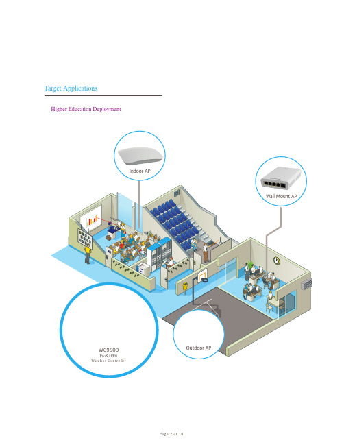
The NETGEAR WC9500 High Capacity Wireless Controller supports rapid mobility across VLANs and subnets including 802.11i preauthentication and fast roaming support (FRS). Seamless L2 and L3 roaming provides support for latency-sensitive applications such as video, audio and voice over wireless. WiFi Multimedia (WMM) advanced prioritization extends WiFi s high-quality end-user experience to voice applications (VoWiFi).
WAC730
Description
Part Numbers
WAC720 WNDAP660
Typical Deployment
Product Image (Front)
Product Image (Back)
WNDAP620
WNDAP360
WNDAP350 WNAP320 WNAP210 WN370 WND930
Page 3 of 10
Features
Scalable Architecture
The NETGEAR WC9500 High Capacity Controller supports up to 200 APs and is upgradable in 10, 50, 100, or 200 APs via so ware licenses. Stackable up to three controllers, a WC9500 High Capacity Controller stack can support up to 600 access points with a single interface. The WC9500 o ers redundancy for always-on reliability.
Cepa W901 Simple WiFi AP 转换器 说明书
W901 Simple WiFi AP(W901 口袋型無線網路轉換器) 使用手冊Copyright© 2010 Cepa Electronics Group Inc.No part of this manual, including the products and software described in it, may be reproduced, transmitted, transcribed, stored in a retrieval system, or translated into any language in any form or by any means, except documentation kept by the purchaser for backup purposes, without the express written permission of Cepa Electronic Group Inc., (“CepaGroup”).Product warranty or service will not be extended if: (1) the product is repaired, modified or altered, unless such repair, modification of alteration is authorized in writing by CepaGroup; or (2) the serial number of the product is defaced or missing. CEPAGROUP PROVIDES THIS MANUAL “AS IS” WITHOUT WARRANTY OF ANY KIND, EITHER EXPRESS OR IMPLIED, INCLUDING BUT NOT LIMITED TO THE IMPLIED WARRANTIES OR CONDITIONS OF MERCHANTABILITY OR FITNESS FOR A PARTICULAR PURPOSE. IN NO EVENT SHALL CEPAGROUP, ITS DIRECTORS, OFFICERS, EMPLOYEES OR AGENTS BE LIABLE FOR ANY INDIRECT, SPECIAL, INCIDENTAL, OR CONSEQUENTIAL DAMAGES (INCLUDING DAMAGES FOR LOSS OF PROFITS, LOSS OF BUSINESS, LOSS OF USE OR DATA, INTERRUPTION OF BUSINESS AND THE LIKE), EVEN IF CEPAGROUP HAS BEEN ADVISED OF THE POSSIBILITY OF SUCH DAMAGES ARISING FROM ANY DEFECT OR ERROR IN THIS MANUAL OR PRODUCT.SPECIFICATIONS AND INFORMATION CONTAINED IN THIS MANUAL ARE FURNISHED FOR INFORMATIONAL USE ONLY, AND ARE SUBJECT TO CHANGE AT ANY TIME WITHOUT NOTICE, AND SHOULD NOT BE CONSTRUED AS A COMMITMENT BY CEPAGROUP. CEPAGROUP ASSUMES NO RESPONSIBILITY OR LIABILITY FOR ANY ERRORS OR INACCURACIES THAT MAY APPEAR IN THIS MANUAL, INCLUDING THE PRODUCTS AND SOFTWARE DESCRIBED IN IT.Products and corporate names appearing in this manual may or may not be registered trademarks or copyrights of their respective companies, and are used only for identification or explanation and to the owners’ benefit, without intent to infringe. First EditionDec. 2010目錄1. W901 產品簡介 (4)2. W901 快速啟用導覽 (5)1) 外觀介面示意圖 (5)2) W901接線示意圖 (5)3) W901 快速啟用操作範例 ( 以Windows XP為例) (6)3. 變更W901 網路名稱(SSID) 及密碼 (8)4. 固定式IP網路環境之設定 (10)5. 撥接網路連線環境之設定 (14)6. 附錄 (16)1) 連線至區域網路(LAN)環境時之注意事項 (16)2) 直接連線至數據機時之注意事項 (17)3) 智慧型手機 (以iPhone為例) 的連線設定 (18)1.W901 產品簡介不用再被繁複的無線設定困擾了,無論你的有線網路是LAN/ ADSL/ Cable/ 撥接網路,有了 W901口袋型無線AP您就可以立刻輕鬆將有線環境轉換成無線WiFi環境,讓您的手機、電腦、 遊戲機等無線裝置立刻無線上網。
ProSAFE WC9500 无线控制器安装指南说明书
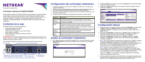
Guía de instalaciónControlador inalámbrico ProSAFE® WC9500El controlador inalámbrico ProSAFE WC9500 le permite gestionar una red inalámbrica grande desde un punto central, implementar las funciones de seguridad de forma central, admitir itinerancia rápida de capa 2 y capa 3, configurar un portal cautivo con acceso de invitados, y soporte de voz sobre Wi-Fi (VoWi-Fi). En esta guía deinstalación, el controlador inalámbrico ProSAFE WC9500 se denomina "controlador inalámbrico".Contenido de la cajaEl paquete contiene los siguientes elementos:•Controlador inalámbrico WC9500•Cable de alimentación de CA•Cable Ethernet de categoría 5 de conexión directa•Kit de montaje en bastidor•Patas de goma (4), cuya parte posterior es adhesiva•Guía de instalaciónADVERTENCIA:NO coloque los dispositivos uno encima del otro (en una pila), ni en espacios reducidos o cajones. Asegúrese de que hay un espacio libre de al menos 5 cm alrededor del equipo para que ventile.En la siguiente ilustración se muestra solo el lateral izquierdo del panel frontal:Configuración del controlador inalámbrico1.Configure el equipo con la dirección IP estática 192.168.0.210 y la máscara desubred 255.255.255.0.2.Conecte un extremo del cable Ethernet proporcionado al puerto Ethernet del equipo y elotro extremo al puerto Ethernet del panel frontal del controlador inalámbrico.3.Conecte el cable de alimentación proporcionado del controlador inalámbrico a unatoma de corriente de CA.pruebe que se encienden los siguientes indicadores en el panel frontal:Acceso al controlador inalámbrico1.En el equipo, abra una ventana del navegador. En el campo de dirección, escribahttp://192.168.0.250. Se muestra la pantalla de inicio de sesión del controladorIndicador DescripciónEntrada de lafuente dealimentaciónEl indicador de alimentación verde está iluminado. En caso contrario,compruebe las conexiones y cualquier interruptor en la toma de corrienteque pudiera estar apagado.Estado El indicador de estado se ilumina en amarillo mientras el controladorinalámbrico se está inicializando. Después de aproximadamente dosminutos, cuando el controlador inalámbrico ha completado su inicialización,el indicador de estado se ilumina en verde.Rejilla deventilaciónEl indicador de ventilador verde está encendido, lo que indica que losventiladores están funcionando correctamente.PuertoEthernetEl indicador de puerto Ethernet de la derecha se ilumina en verde para unaconexión de 1000 Mbps o en amarillo para una conexión de 100 ó 10 Mbps.2.Introduzca admin como nombre de usuario y password como contraseña (utiliceminúsculas en ambos casos).3.Haga clic en Login (Iniciar sesión). Se muestra la interfaz de gestión web delcontrolador inalámbrico.Configuración básica1.Desde el menú de navegación principal, seleccione Configuration (Configuración)> System (Sistema) > General (General). Introduzca un nombre para elcontrolador inalámbrico y seleccione el país en el que se utiliza. Haga clic enApply (Aplicar).2.Seleccione Configuration (Configuración) > System (Sistema) > Time (Hora).Seleccione la zona horaria en la que se utiliza el controlador inalámbrico.(Opcional) Configure las opciones de NTP. Haga clic en Aplicar.3.Seleccione Configuration (Configuración) > System (Sistema) > IP/VLAN.Introduzca la configuración de IP de la red y las VLAN que desea asignar alcontrolador inalámbrico.Nota:Una VLAN de gestión se utiliza para todo el tráfico HTTP y SNMP a y desde elcontrolador inalámbrico y los puntos de acceso gestionados. Para grandesinstalaciones, NETGEAR recomienda que el controlador inalámbrico y los puntos deacceso estén en VLAN independientes para garantizar una conectividad sininterrupciones entre el controlador inalámbrico y los puntos de acceso.Nota:Desactive la casilla Untagged VLAN (VLAN sin etiquetas) sólo si losconcentradores y conmutadores de la red son compatibles con el estándar VLAN(802.1Q). Igualmente, cambie el valor de VLAN sin etiquetar sólo si los concentradoresy conmutadores de la red son compatibles con el estándar VLAN (802.1Q).Haga clic en Aplicar. La conexión al controlador inalámbrico ha terminadoporque ha cambiado su dirección IP.4.Vuelva a configurar el equipo con una dirección IP y una máscara de subred que seencuentren en la misma subred IP que el controlador inalámbrico. Utilice la nuevadirección IP del controlador inalámbrico para iniciar una nueva sesión.Diciembre de 2013NETGEAR, el logotipo de NETGEAR y Connect with Innovation son marcas comerciales o marcas comerciales registradas de NETGEAR, Inc. o sus filiales en Estados Unidos y otros países. La información contenida en el documento puede sufrir modificaciones sin previo aviso. © NETGEAR, Inc. Todos los derechos reservados.Solo para uso en interiores en todos los estados miembro de la UE, estados EFTA y Suiza.NETGEAR, Inc.350 East Plumeria DriveSan José, CA 95134 Estados Unidos5.Seleccione Configuration (Configuración) > System (Sistema) > DHCP Server (Servidor DHCP). El asistente para la detección (consulte Detección de puntos de acceso ) necesita un servidor DHCP para detectar los puntos de acceso. Si ya dispone de un servidor DHCP en la red, desactive el servidor DHCP en el controladorinalámbrico. De lo contrario, configure los ajustes DHCP para el servidor DHCP en el controlador inalámbrico. Haga clic en Aplicar .6.Determine si desea utilizar el grupo de perfiles básicos (apto para una WLAN pequeña) o uno o más grupos de perfiles avanzados (apto para una WLAN grande):•El grupo de perfiles básico del controlador inalámbrico incluye todas las características que se pueden configurar en un punto de acceso: hasta 8 perfiles (16 para los puntos de acceso de banda dual), cada uno de los cuales tiene su propio SSID, seguridad, ACL de MAC, configuración de limitación de velocidad, ajustes WMM, etc.Seleccione Configuration (Configuración) > Profile (Perfil) > Basic (Básico) > Radio (Radio). Configure uno o más perfiles, cada uno con su configuración de SSID y de seguridad. Haga clic en Apply (Aplicar) después de haber configurado un perfil.•El perfil avanzado le permite configurar hasta 8 grupos perfil. Cada grupo incluye todos los ajustes que son necesarios para configurar un punto de acceso totalmente funcional con hasta 8 perfiles de seguridad (16 puntos de acceso de banda dual).Seleccione Configuration (Configuración) > Profile (Perfil) > Advanced(Avanzado) > Radio (Radio). Configure uno o más grupos de perfiles, cada uno con uno o más perfiles con su propia configuración de SSID y de seguridad. Haga clic en Apply (Aplicar) después de haber configurado un perfil.Nota:Para obtener más información sobre las opciones de configuración del controlador inalámbrico, incluidos los grupos de perfiles, consulte el manual de referencia.Instalación del controlador inalámbrico1.Desconecte el cable de alimentación del controlador inalámbrico.2.Desconecte el controlador inalámbrico del equipo y sitúelo donde desee instalarlo.3.Conecte un extremo de un cable Ethernet a un puerto LAN en un router o conmutador de la red y el otro extremo al puerto Ethernet del panel frontal del controlador inalámbrico.4.Vuelva a conectar el cable de alimentación desde el controlador inalámbrico a una toma de corriente de CA. Los indicadores se iluminan como se describe en Configuración del controlador inalámbrico .Detección de puntos de accesoEl controlador inalámbrico gestiona los puntos de acceso de NETGEAR seleccionados. Para obtener una lista de los puntos de acceso de NETGEAR compatibles, visite el sitio web de asistencia técnica de NETGEAR. Si el controlador inalámbrico y los puntos de acceso están conectados a través de la red en la misma capa 2, el asistente para la detecciónpuede detectar puntos de acceso que se encuentren en estado predeterminado de fábrica o ya instalados y en funcionamiento.Para que el asistente para la detección detecte puntos de acceso a través de una red de capa 3 (detrás de un router) o puntos de acceso remoto, se tienen que cumplir los siguientes requisitos:•La red debe disponer de un servidor DHCP que tenga la opción 43 activada con ladirección IP del controlador inalámbrico, o el servidor DHCP del controlador inalámbrico debe ser accesible para todos los puntos de acceso.•Cada punto de acceso debe tener una dirección IP .•Cada punto de acceso debe tener SNMP y SSH activado (que es el valorpredeterminado).•El cortafuegos debe desbloquear el número de puerto UDP 7890.Para que el controlador inalámbrico detecte puntos de acceso:1.Acceda al controlador inalámbrico en la dirección IP de red que ha configurado enConfiguración básica .2.Seleccione Access Point (Punto de acceso) > Discovery (Detección) > DiscoveryWizard (Asistente de detección). Siga los pasos que aparecen en pantalla para detectar los puntos de acceso y revise los resultados de la detección.3.Seleccione Access Point (Punto de acceso) > Discovery (Detección) > ManagedAP List (Lista de PA gestionados). Agregue los puntos de acceso que desee que gestione el controlador inalámbrico a la lista de puntos de acceso gestionados.Aunque los puntos de acceso se convierte de modo autónomo a modo gestionado, ocurre lo siguiente:•El controlador inalámbrico inserta el firmware de gestión en los puntos de acceso.•Los puntos de acceso se convierten en clientes DHCP y reciben una dirección IP delservidor DHCP en la red o del servidor DHCP en el controlador inalámbrico.•Los perfiles que ha configurado en el controlador inalámbrico se insertan en lospuntos de acceso.Nota:Para obtener más información sobre el asistente para la detección y el proceso de detección, consulte el manual de referencia.Solución de problemasNo se puede acceder al controlador inalámbrico en su dirección IP predeterminada (192.168.0.250):•Compruebe que el equipo esté conectado a un controlador inalámbrico.•Puede que no haya reiniciado el equipo con el controlador inalámbrico para que seapliquen los cambios de TCP/IP . Reinicie el ordenador.•El equipo puede estar configurado para activar NetBIOS a través de TCP/IP .Compruebe que el TCP/IP está configurado para utilizar una dirección IP estática 192.168.0.210 y la máscara de subred 255.255.255.0. (La configuración TCP/IP predeterminada para Windows es obtener una dirección IP automáticamente.) Reinicie el equipo.Después de la configuración inicial, no se puede acceder al controlador inalámbrico en su propia dirección de red:•Utilice el comando ping para comprobar la conexión.•Compruebe que el equipo y el controlador inalámbrico están en la misma VLAN.•Puede que alguna configuración predeterminada del controlador inalámbrico nofuncione con la red. Compruebe la configuración predeterminada del controlador inalámbrico comparándola con la del resto de dispositivos de la red.SoporteGracias por elegir un producto NETGEAR.Una vez instalado el controlador inalámbrico, busque el número de serie en la etiqueta y regístrelo en https:// .Deberá registrar su controlador inalámbrico para poder hacer uso de nuestro servicio telefónico de asistencia NETGEAR. NETGEAR recomienda registrar su controlador inalámbrico a través de la página web de NETGEAR. Podrá encontrar actualizaciones del producto y asistencia técnica en .NETGEAR le recomienda que utilice solo los recursos del servicio técnico oficial de NETGEAR.Encontrará el manual de referencia en línea en o a través de un vínculo en la interfaz de usuario del controlador inalámbrico.Para consultar la declaración de conformidad de la UE actual, visite/app/answers/detail/a_id/11621/.。
