MD3000-06.17.77.60-shelloutput
MCD3000操作说明
MCD3000操作说明步骤一:准备工作1.在计算机上安装MCD3000软件,并确保软件已经正确启动。
2.将MCD3000软启动设备连接到计算机的USB接口上。
步骤二:设置启动顺序1. 打开计算机的BIOS设置界面,一般可以通过按下"Del"或"F2"键来进入。
2. 在BIOS设置界面中找到"Boot"或"BIOS Boot"选项,并进入该菜单。
3. 找到"Boot Device Priority"或类似的选项,并选择"MCD3000"作为第一启动设备。
4.保存设置并退出BIOS设置界面。
步骤三:重启计算机1.关闭计算机,并重新启动。
2. 在计算机重新启动时,屏幕上会显示"Press any key to boot from MCD3000"的提示信息。
3.在提示信息出现后,立即按下键盘上的任意键。
4.此时,计算机会从MCD3000设备启动。
步骤四:选择操作模式1.在MCD3000的启动界面中,会显示几种不同的操作模式选项,如"安装操作系统"、"备份与恢复"、"磁盘工具"等。
2.使用方向键选择你想要进行的操作模式,并按下回车键确认选择。
3.根据所选择的操作模式,MCD3000会加载相应的工具和资源。
步骤五:进行实际操作1.根据所选择的操作模式,MCD3000会提供相应的操作界面和指导。
2.按照界面上的提示,进行相应的操作,如安装操作系统、备份数据、磁盘分区等。
3.在操作过程中,可以根据需要选择不同的选项来完成各种操作。
4.操作完成后,可以选择退出MCD3000,或重新启动计算机。
需要注意的是,MCD3000软启动工具具有一定的风险性,如果操作不当可能会导致数据丢失或系统无法正常启动。
因此,在使用MCD3000进行软启动操作时,请务必按照官方说明和操作手册进行操作,并提前备份重要数据。
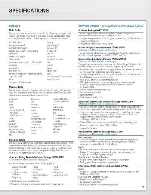
Tektronix MDO3000 Series 数字多功能作业仪用户指南说明书
19StandardMath ToolsDisplay up to four math function traces (F1-F4). The easy-to-use graphical interface simplifies setup of up to two operations on each function trace;and function traces can be chained together to perform math-on-math.absolute value integralaverage (summed)invert (negate)average (continuous)log (base e)custom (MATLAB) – limited points product (x)derivativeratio (/)deskew (resample)reciprocaldifference (–)rescale (with units)enhanced resolution (to 11 bits vertical)roof envelope (sinx)/x exp (base e)square exp (base 10)square root fft (power spectrum, magnitude, phase,sum (+)up to 50 kpts) trend (datalog) of 1000 events floorzoom (identity)histogram of 1000 eventsMeasure ToolsDisplay any 6 parameters together with statistics, including their average,high, low, and standard deviations. Histicons provide a fast, dynamic view of parameters and wave-shape characteristics.Pass/Fail TestingSimultaneously test multiple parameters against selectable parameter limits or pre-defined masks. Pass or fail conditions can initiate actions including document to local or networked files, e-mail the image of the failure, save waveforms, send a pulse out at the rear panel auxiliary BNC output, or (with the GPIB option) send a GPIB SRQ.Jitter and Timing Analysis Software Package (WRXi-JTA2)(Standard with MXi-A model oscilloscopes)•Jitter and timing parameters, with “Track”graphs of •Edge@lv parameter (counts edges)• Persistence histogram, persistence trace (mean, range, sigma)Software Options –Advanced Math and WaveShape AnalysisStatistics Package (WRXi-STAT)This package provides additional capability to statistically display measurement information and to analyze results:• Histograms expanded with 19 histogram parameters/up to 2 billion events.• Persistence Histogram• Persistence Trace (mean, range, sigma)Master Analysis Software Package (WRXi-XMAP)(Standard with MXi-A model oscilloscopes)This package provides maximum capability and flexibility, and includes all the functionality present in XMATH, XDEV, and JTA2.Advanced Math Software Package (WRXi-XMATH)(Standard with MXi-A model oscilloscopes)This package provides a comprehensive set of WaveShape Analysis tools providing insight into the wave shape of complex signals. Includes:•Parameter math – add, subtract, multiply, or divide two different parameters.Invert a parameter and rescale parameter values.•Histograms expanded with 19 histogram parameters/up to 2 billion events.•Trend (datalog) of up to 1 million events•Track graphs of any measurement parameter•FFT capability includes: power averaging, power density, real and imaginary components, frequency domain parameters, and FFT on up to 24 Mpts.•Narrow-band power measurements •Auto-correlation function •Sparse function• Cubic interpolation functionAdvanced Customization Software Package (WRXi-XDEV)(Standard with MXi-A model oscilloscopes)This package provides a set of tools to modify the scope and customize it to meet your unique needs. Additional capability provided by XDEV includes:•Creation of your own measurement parameter or math function, using third-party software packages, and display of the result in the scope. Supported third-party software packages include:– VBScript – MATLAB – Excel•CustomDSO – create your own user interface in a scope dialog box.• Addition of macro keys to run VBScript files •Support for plug-insValue Analysis Software Package (WRXi-XVAP)(Standard with MXi-A model oscilloscopes)Measurements:•Jitter and Timing parameters (period@level,width@level, edge@level,duty@level, time interval error@level, frequency@level, half period, setup, skew, Δ period@level, Δ width@level).Math:•Persistence histogram •Persistence trace (mean, sigma, range)•1 Mpts FFTs with power spectrum density, power averaging, real, imaginary, and real+imaginary settings)Statistical and Graphical Analysis•1 Mpts Trends and Histograms •19 histogram parameters •Track graphs of any measurement parameterIntermediate Math Software Package (WRXi-XWAV)Math:•1 Mpts FFTs with power spectrum density, power averaging, real, and imaginary componentsStatistical and Graphical Analysis •1 Mpts Trends and Histograms •19 histogram parameters•Track graphs of any measurement parameteramplitude area base cyclescustom (MATLAB,VBScript) –limited points delay Δdelay duration duty cyclefalltime (90–10%, 80–20%, @ level)firstfrequency lastlevel @ x maximum mean median minimumnumber of points +overshoot –overshoot peak-to-peak period phaserisetime (10–90%, 20–80%, @ level)rmsstd. deviation time @ level topΔ time @ levelΔ time @ level from triggerwidth (positive + negative)x@ max.x@ min.– Cycle-Cycle Jitter – N-Cycle– N-Cycle with start selection – Frequency– Period – Half Period – Width– Time Interval Error – Setup– Hold – Skew– Duty Cycle– Duty Cycle Error20WaveRunner WaveRunner WaveRunner WaveRunner WaveRunner 44Xi-A64Xi-A62Xi-A104Xi-A204Xi-AVertical System44MXi-A64MXi-A104MXi-A204MXi-ANominal Analog Bandwidth 400 MHz600 MHz600 MHz 1 GHz 2 GHz@ 50 Ω, 10 mV–1 V/divRise Time (Typical)875 ps500 ps500 ps300 ps180 psInput Channels44244Bandwidth Limiters20 MHz; 200 MHzInput Impedance 1 MΩ||16 pF or 50 Ω 1 MΩ||20 pF or 50 ΩInput Coupling50 Ω: DC, 1 MΩ: AC, DC, GNDMaximum Input Voltage50 Ω: 5 V rms, 1 MΩ: 400 V max.50 Ω: 5 V rms, 1 MΩ: 250 V max.(DC + Peak AC ≤ 5 kHz)(DC + Peak AC ≤ 10 kHz)Vertical Resolution8 bits; up to 11 with enhanced resolution (ERES)Sensitivity50 Ω: 2 mV/div–1 V/div fully variable; 1 MΩ: 2 mV–10 V/div fully variableDC Gain Accuracy±1.0% of full scale (typical); ±1.5% of full scale, ≥ 10 mV/div (warranted)Offset Range50 Ω: ±1 V @ 2–98 mV/div, ±10 V @ 100 mV/div–1 V/div; 50Ω:±400mV@2–4.95mV/div,±1V@5–99mv/div,1 M Ω: ±1 V @ 2–98 mV/div, ±10 V @ 100 mV/div–1 V/div,±10 V @ 100 mV–1 V/div±**********/div–10V/div 1 M Ω: ±400 mV @ 2–4.95 mV/div, ±1 V @5–99 mV/div, ±10 V @ 100 mV–1 V/div,±*********–10V/divInput Connector ProBus/BNCTimebase SystemTimebases Internal timebase common to all input channels; an external clock may be applied at the auxiliary inputTime/Division Range Real time: 200 ps/div–10 s/div, RIS mode: 200 ps/div to 10 ns/div, Roll mode: up to 1,000 s/divClock Accuracy≤ 5 ppm @ 25 °C (typical) (≤ 10 ppm @ 5–40 °C)Sample Rate and Delay Time Accuracy Equal to Clock AccuracyChannel to Channel Deskew Range±9 x time/div setting, 100 ms max., each channelExternal Sample Clock DC to 600 MHz; (DC to 1 GHz for 104Xi-A/104MXi-A and 204Xi-A/204MXi-A) 50 Ω, (limited BW in 1 MΩ),BNC input, limited to 2 Ch operation (1 Ch in 62Xi-A), (minimum rise time and amplitude requirements applyat low frequencies)Roll Mode User selectable at ≥ 500 ms/div and ≤100 kS/s44Xi-A64Xi-A62Xi-A104Xi-A204Xi-A Acquisition System44MXi-A64MXi-A104MXi-A204MXi-ASingle-Shot Sample Rate/Ch 5 GS/sInterleaved Sample Rate (2 Ch) 5 GS/s10 GS/s10 GS/s10 GS/s10 GS/sRandom Interleaved Sampling (RIS)200 GS/sRIS Mode User selectable from 200 ps/div to 10 ns/div User selectable from 100 ps/div to 10 ns/div Trigger Rate (Maximum) 1,250,000 waveforms/secondSequence Time Stamp Resolution 1 nsMinimum Time Between 800 nsSequential SegmentsAcquisition Memory Options Max. Acquisition Points (4 Ch/2 Ch, 2 Ch/1 Ch in 62Xi-A)Segments (Sequence Mode)Standard12.5M/25M10,00044Xi-A64Xi-A62Xi-A104Xi-A204Xi-A Acquisition Processing44MXi-A64MXi-A104MXi-A204MXi-ATime Resolution (min, Single-shot)200 ps (5 GS/s)100 ps (10 GS/s)100 ps (10 GS/s)100 ps (10 GS/s)100 ps (10 GS/s) Averaging Summed and continuous averaging to 1 million sweepsERES From 8.5 to 11 bits vertical resolutionEnvelope (Extrema)Envelope, floor, or roof for up to 1 million sweepsInterpolation Linear or (Sinx)/xTrigger SystemTrigger Modes Normal, Auto, Single, StopSources Any input channel, External, Ext/10, or Line; slope and level unique to each source, except LineTrigger Coupling DC, AC (typically 7.5 Hz), HF Reject, LF RejectPre-trigger Delay 0–100% of memory size (adjustable in 1% increments, or 100 ns)Post-trigger Delay Up to 10,000 divisions in real time mode, limited at slower time/div settings in roll modeHold-off 1 ns to 20 s or 1 to 1,000,000,000 events21WaveRunner WaveRunner WaveRunner WaveRunner WaveRunner 44Xi-A 64Xi-A 62Xi-A104Xi-A 204Xi-A Trigger System (cont’d)44MXi-A64MXi-A104MXi-A204MXi-AInternal Trigger Level Range ±4.1 div from center (typical)Trigger and Interpolator Jitter≤ 3 ps rms (typical)Trigger Sensitivity with Edge Trigger 2 div @ < 400 MHz 2 div @ < 600 MHz 2 div @ < 600 MHz 2 div @ < 1 GHz 2 div @ < 2 GHz (Ch 1–4 + external, DC, AC, and 1 div @ < 200 MHz 1 div @ < 200 MHz 1 div @ < 200 MHz 1 div @ < 200 MHz 1 div @ < 200 MHz LFrej coupling)Max. Trigger Frequency with400 MHz 600 MHz 600 MHz 1 GHz2 GHzSMART Trigger™ (Ch 1–4 + external)@ ≥ 10 mV@ ≥ 10 mV@ ≥ 10 mV@ ≥ 10 mV@ ≥ 10 mVExternal Trigger RangeEXT/10 ±4 V; EXT ±400 mVBasic TriggersEdgeTriggers when signal meets slope (positive, negative, either, or Window) and level conditionTV-Composite VideoT riggers NTSC or PAL with selectable line and field; HDTV (720p, 1080i, 1080p) with selectable frame rate (50 or 60 Hz)and Line; or CUSTOM with selectable Fields (1–8), Lines (up to 2000), Frame Rates (25, 30, 50, or 60 Hz), Interlacing (1:1, 2:1, 4:1, 8:1), or Synch Pulse Slope (Positive or Negative)SMART TriggersState or Edge Qualified Triggers on any input source only if a defined state or edge occurred on another input source.Delay between sources is selectable by time or eventsQualified First In Sequence acquisition mode, triggers repeatedly on event B only if a defined pattern, state, or edge (event A) is satisfied in the first segment of the acquisition. Delay between sources is selectable by time or events Dropout Triggers if signal drops out for longer than selected time between 1 ns and 20 s.PatternLogic combination (AND, NAND, OR, NOR) of 5 inputs (4 channels and external trigger input – 2 Ch+EXT on WaveRunner 62Xi-A). Each source can be high, low, or don’t care. The High and Low level can be selected independently. Triggers at start or end of the patternSMART Triggers with Exclusion TechnologyGlitch and Pulse Width Triggers on positive or negative glitches with widths selectable from 500 ps to 20 s or on intermittent faults (subject to bandwidth limit of oscilloscope)Signal or Pattern IntervalTriggers on intervals selectable between 1 ns and 20 sTimeout (State/Edge Qualified)Triggers on any source if a given state (or transition edge) has occurred on another source.Delay between sources is 1 ns to 20 s, or 1 to 99,999,999 eventsRuntTrigger on positive or negative runts defined by two voltage limits and two time limits. Select between 1 ns and 20 sSlew RateTrigger on edge rates. Select limits for dV, dt, and slope. Select edge limits between 1 ns and 20 s Exclusion TriggeringTrigger on intermittent faults by specifying the normal width or periodLeCroy WaveStream Fast Viewing ModeIntensity256 Intensity Levels, 1–100% adjustable via front panel control Number of Channels up to 4 simultaneouslyMax Sampling Rate5 GS/s (10 GS/s for WR 62Xi-A, 64Xi-A/64MXi-A,104Xi-A/104MXi-A, 204Xi-A/204MXi-A in interleaved mode)Waveforms/second (continuous)Up to 20,000 waveforms/secondOperationFront panel toggle between normal real-time mode and LeCroy WaveStream Fast Viewing modeAutomatic SetupAuto SetupAutomatically sets timebase, trigger, and sensitivity to display a wide range of repetitive signalsVertical Find ScaleAutomatically sets the vertical sensitivity and offset for the selected channels to display a waveform with maximum dynamic range44Xi-A 64Xi-A 62Xi-A104Xi-A 204Xi-A Probes44MXi-A 64MXi-A104MXi-A 204MXi-AProbesOne Passive probe per channel; Optional passive and active probes available Probe System; ProBus Automatically detects and supports a variety of compatible probes Scale FactorsAutomatically or manually selected, depending on probe usedColor Waveform DisplayTypeColor 10.4" flat-panel TFT-LCD with high resolution touch screenResolutionSVGA; 800 x 600 pixels; maximum external monitor output resolution of 2048 x 1536 pixelsNumber of Traces Display a maximum of 8 traces. Simultaneously display channel, zoom, memory, and math traces Grid StylesAuto, Single, Dual, Quad, Octal, XY , Single + XY , Dual + XY Waveform StylesSample dots joined or dots only in real-time mode22Zoom Expansion TracesDisplay up to 4 Zoom/Math traces with 16 bits/data pointInternal Waveform MemoryM1, M2, M3, M4 Internal Waveform Memory (store full-length waveform with 16 bits/data point) or store to any number of files limited only by data storage mediaSetup StorageFront Panel and Instrument StatusStore to the internal hard drive, over the network, or to a USB-connected peripheral deviceInterfaceRemote ControlVia Windows Automation, or via LeCroy Remote Command Set Network Communication Standard VXI-11 or VICP , LXI Class C Compliant GPIB Port (Accessory)Supports IEEE – 488.2Ethernet Port 10/100/1000Base-T Ethernet interface (RJ-45 connector)USB Ports5 USB 2.0 ports (one on front of instrument) supports Windows-compatible devices External Monitor Port Standard 15-pin D-Type SVGA-compatible DB-15; connect a second monitor to use extended desktop display mode with XGA resolution Serial PortDB-9 RS-232 port (not for remote oscilloscope control)44Xi-A 64Xi-A 62Xi-A104Xi-A 204Xi-A Auxiliary Input44MXi-A 64MXi-A104MXi-A 204MXi-ASignal Types Selected from External Trigger or External Clock input on front panel Coupling50 Ω: DC, 1 M Ω: AC, DC, GND Maximum Input Voltage50 Ω: 5 V rms , 1 M Ω: 400 V max.50 Ω: 5 V rms , 1 M Ω: 250 V max. (DC + Peak AC ≤ 5 kHz)(DC + Peak AC ≤ 10 kHz)Auxiliary OutputSignal TypeTrigger Enabled, Trigger Output. Pass/Fail, or Off Output Level TTL, ≈3.3 VConnector TypeBNC, located on rear panelGeneralAuto Calibration Ensures specified DC and timing accuracy is maintained for 1 year minimumCalibratorOutput available on front panel connector provides a variety of signals for probe calibration and compensationPower Requirements90–264 V rms at 50/60 Hz; 115 V rms (±10%) at 400 Hz, Automatic AC Voltage SelectionInstallation Category: 300 V CAT II; Max. Power Consumption: 340 VA/340 W; 290 VA/290 W for WaveRunner 62Xi-AEnvironmentalTemperature: Operating+5 °C to +40 °C Temperature: Non-Operating -20 °C to +60 °CHumidity: Operating Maximum relative humidity 80% for temperatures up to 31 °C decreasing linearly to 50% relative humidity at 40 °CHumidity: Non-Operating 5% to 95% RH (non-condensing) as tested per MIL-PRF-28800F Altitude: OperatingUp to 3,048 m (10,000 ft.) @ ≤ 25 °C Altitude: Non-OperatingUp to 12,190 m (40,000 ft.)PhysicalDimensions (HWD)260 mm x 340 mm x 152 mm Excluding accessories and projections (10.25" x 13.4" x 6")Net Weight7.26kg. (16.0lbs.)CertificationsCE Compliant, UL and cUL listed; Conforms to EN 61326, EN 61010-1, UL 61010-1 2nd Edition, and CSA C22.2 No. 61010-1-04Warranty and Service3-year warranty; calibration recommended annually. Optional service programs include extended warranty, upgrades, calibration, and customization services23Product DescriptionProduct CodeWaveRunner Xi-A Series Oscilloscopes2 GHz, 4 Ch, 5 GS/s, 12.5 Mpts/ChWaveRunner 204Xi-A(10 GS/s, 25 Mpts/Ch in interleaved mode)with 10.4" Color Touch Screen Display 1 GHz, 4 Ch, 5 GS/s, 12.5 Mpts/ChWaveRunner 104Xi-A(10 GS/s, 25 Mpts/Ch in interleaved mode)with 10.4" Color Touch Screen Display 600 MHz, 4 Ch, 5 GS/s, 12.5 Mpts/Ch WaveRunner 64Xi-A(10 GS/s, 25 Mpts/Ch in interleaved mode)with 10.4" Color Touch Screen Display 600 MHz, 2 Ch, 5 GS/s, 12.5 Mpts/Ch WaveRunner 62Xi-A(10 GS/s, 25 Mpts/Ch in interleaved mode)with 10.4" Color Touch Screen Display 400 MHz, 4 Ch, 5 GS/s, 12.5 Mpts/Ch WaveRunner 44Xi-A(25 Mpts/Ch in interleaved mode)with 10.4" Color Touch Screen DisplayWaveRunner MXi-A Series Oscilloscopes2 GHz, 4 Ch, 5 GS/s, 12.5 Mpts/ChWaveRunner 204MXi-A(10 GS/s, 25 Mpts/Ch in Interleaved Mode)with 10.4" Color Touch Screen Display 1 GHz, 4 Ch, 5 GS/s, 12.5 Mpts/ChWaveRunner 104MXi-A(10 GS/s, 25 Mpts/Ch in Interleaved Mode)with 10.4" Color Touch Screen Display 600 MHz, 4 Ch, 5 GS/s, 12.5 Mpts/Ch WaveRunner 64MXi-A(10 GS/s, 25 Mpts/Ch in Interleaved Mode)with 10.4" Color Touch Screen Display 400 MHz, 4 Ch, 5 GS/s, 12.5 Mpts/Ch WaveRunner 44MXi-A(25 Mpts/Ch in Interleaved Mode)with 10.4" Color Touch Screen DisplayIncluded with Standard Configuration÷10, 500 MHz, 10 M Ω Passive Probe (Total of 1 Per Channel)Standard Ports; 10/100/1000Base-T Ethernet, USB 2.0 (5), SVGA Video out, Audio in/out, RS-232Optical 3-button Wheel Mouse – USB 2.0Protective Front Cover Accessory PouchGetting Started Manual Quick Reference GuideAnti-virus Software (Trial Version)Commercial NIST Traceable Calibration with Certificate 3-year WarrantyGeneral Purpose Software OptionsStatistics Software Package WRXi-STAT Master Analysis Software Package WRXi-XMAP (Standard with MXi-A model oscilloscopes)Advanced Math Software Package WRXi-XMATH (Standard with MXi-A model oscilloscopes)Intermediate Math Software Package WRXi-XWAV (Standard with MXi-A model oscilloscopes)Value Analysis Software Package (Includes XWAV and JTA2) WRXi-XVAP (Standard with MXi-A model oscilloscopes)Advanced Customization Software Package WRXi-XDEV (Standard with MXi-A model oscilloscopes)Spectrum Analyzer and Advanced FFT Option WRXi-SPECTRUM Processing Web Editor Software Package WRXi-XWEBProduct Description Product CodeApplication Specific Software OptionsJitter and Timing Analysis Software Package WRXi-JTA2(Standard with MXi-A model oscilloscopes)Digital Filter Software PackageWRXi-DFP2Disk Drive Measurement Software Package WRXi-DDM2PowerMeasure Analysis Software Package WRXi-PMA2Serial Data Mask Software PackageWRXi-SDM QualiPHY Enabled Ethernet Software Option QPHY-ENET*QualiPHY Enabled USB 2.0 Software Option QPHY-USB †EMC Pulse Parameter Software Package WRXi-EMC Electrical Telecom Mask Test PackageET-PMT* TF-ENET-B required. †TF-USB-B required.Serial Data OptionsI 2C Trigger and Decode Option WRXi-I2Cbus TD SPI Trigger and Decode Option WRXi-SPIbus TD UART and RS-232 Trigger and Decode Option WRXi-UART-RS232bus TD LIN Trigger and Decode Option WRXi-LINbus TD CANbus TD Trigger and Decode Option CANbus TD CANbus TDM Trigger, Decode, and Measure/Graph Option CANbus TDM FlexRay Trigger and Decode Option WRXi-FlexRaybus TD FlexRay Trigger and Decode Physical Layer WRXi-FlexRaybus TDP Test OptionAudiobus Trigger and Decode Option WRXi-Audiobus TDfor I 2S , LJ, RJ, and TDMAudiobus Trigger, Decode, and Graph Option WRXi-Audiobus TDGfor I 2S LJ, RJ, and TDMMIL-STD-1553 Trigger and Decode Option WRXi-1553 TDA variety of Vehicle Bus Analyzers based on the WaveRunner Xi-A platform are available.These units are equipped with a Symbolic CAN trigger and decode.Mixed Signal Oscilloscope Options500 MHz, 18 Ch, 2 GS/s, 50 Mpts/Ch MS-500Mixed Signal Oscilloscope Option 250 MHz, 36 Ch, 1 GS/s, 25 Mpts/ChMS-500-36(500 MHz, 18 Ch, 2 GS/s, 50 Mpts/Ch Interleaved) Mixed Signal Oscilloscope Option 250 MHz, 18 Ch, 1 GS/s, 10 Mpts/Ch MS-250Mixed Signal Oscilloscope OptionProbes and Amplifiers*Set of 4 ZS1500, 1.5 GHz, 0.9 pF , 1 M ΩZS1500-QUADPAK High Impedance Active ProbeSet of 4 ZS1000, 1 GHz, 0.9 pF , 1 M ΩZS1000-QUADPAK High Impedance Active Probe 2.5 GHz, 0.7 pF Active Probe HFP25001 GHz Active Differential Probe (÷1, ÷10, ÷20)AP034500 MHz Active Differential Probe (x10, ÷1, ÷10, ÷100)AP03330 A; 100 MHz Current Probe – AC/DC; 30 A rms ; 50 A rms Pulse CP03130 A; 50 MHz Current Probe – AC/DC; 30 A rms ; 50 A rms Pulse CP03030 A; 50 MHz Current Probe – AC/DC; 30 A rms ; 50 A peak Pulse AP015150 A; 10 MHz Current Probe – AC/DC; 150 A rms ; 500 A peak Pulse CP150500 A; 2 MHz Current Probe – AC/DC; 500 A rms ; 700 A peak Pulse CP5001,400 V, 100 MHz High-Voltage Differential Probe ADP3051,400 V, 20 MHz High-Voltage Differential Probe ADP3001 Ch, 100 MHz Differential Amplifier DA1855A*A wide variety of other passive, active, and differential probes are also available.Consult LeCroy for more information.Product Description Product CodeHardware Accessories*10/100/1000Base-T Compliance Test Fixture TF-ENET-B †USB 2.0 Compliance Test Fixture TF-USB-B External GPIB Interface WS-GPIBSoft Carrying Case WRXi-SOFTCASE Hard Transit CaseWRXi-HARDCASE Mounting Stand – Desktop Clamp Style WRXi-MS-CLAMPRackmount Kit WRXi-RACK Mini KeyboardWRXi-KYBD Removable Hard Drive Package (Includes removeable WRXi-A-RHD hard drive kit and two hard drives)Additional Removable Hard DriveWRXi-A-RHD-02* A variety of local language front panel overlays are also available .† Includes ENET-2CAB-SMA018 and ENET-2ADA-BNCSMA.Customer ServiceLeCroy oscilloscopes and probes are designed, built, and tested to ensure high reliability. In the unlikely event you experience difficulties, our digital oscilloscopes are fully warranted for three years, and our probes are warranted for one year.This warranty includes:• No charge for return shipping • Long-term 7-year support• Upgrade to latest software at no chargeLocal sales offices are located throughout the world. Visit our website to find the most convenient location.© 2010 by LeCroy Corporation. All rights reserved. Specifications, prices, availability, and delivery subject to change without notice. Product or brand names are trademarks or requested trademarks of their respective holders.1-800-5-LeCroy WRXi-ADS-14Apr10PDF。
NDMP NAS 选项指南 r17 Arcserve Backup for Windows说明书
列印或提供「文件」複本之權利僅限於軟體的相關授權有效期間。如果該授權因任何原因而終止,使用者有責任向 Arcserve 以書面證明該「文件」的所有複本與部份複本均已經交還 Arcserve 或銷毀。
程式庫。此網站可讓您存取我們的知識庫 (KB) 文件。在這裡,您可以輕 易地搜尋及尋找產品相關的知識庫文章,內容包括許多主要議題和常見 問題的實際測試解決方案。 ■ 您可以透過我們的 [即時聊天] 連結,立即啟動您與 Arcserve 支援團隊的 即時對話。有了 [即時聊天],您的顧慮和問題可以即刻獲得答覆,同時 還能繼續存取該產品。 ■ 您可以加入「Arcserve 全球使用者社群」來詢問與答覆問題、分享秘訣 與技巧、討論最佳做法,以及加入同儕之間的對話。 ■ 您可以開立支援票證。透過線上開立支援票證,我們其中一位與您查詢 產品相關領域的專家會回電給您。
Arcserve® Backup for Windows
NDMP NAS Option Guide
r17
本文件包含內嵌說明系統與文件 (以下稱為「文件」) 僅供您參考之用,且 Arcserve 得隨時予以變更或撤銷。
未經 Arcserve 事先書面同意,任何人不得對本「文件」之任何部份或全部內容進行影印、傳閱、再製、公開、修改或複 製。此「文件」為 Arcserve 之機密與專屬資訊,您不得予以洩漏或 用於任何其他用途,除非 (i) 您與 Arcserve 已另立協 議管理與本「文件」相關之 Arcserve 軟體之使用;或 (ii) 與 Arcserve 另立保密協議同意使用之用途。
Dell PowerVault MD3000i 配置指南说明书
Dell PowerVault MD3000iConfiguration Guide for VMware ESX Server SoftwareJanuary 2008Dell Virtualization Solutions Engineering/vmwareTable of Contents1. Introduction (3)2. Architectural Setup (3)3. iSCSI Connectivity Support (4)4. PowerVault MD3000i Storage Setup and Configuration (4)5. iSCSI Software Initiator Configuration on ESX Server (5)6. Configure iSCSI storage on ESX Server (8)7. References (9)Dell Inc Page 31.IntroductionThe Dell ™PowerVault ™ MD3000i storage solution consists of a standard or high availability configuration. The standard model has a single controller with two 1GbE ports. It can be deployed to support up to 16 hosts non-redundantly. The high availability model has dual controllers with two 1GbE ports per controller for a total of four 1GbE ports. The dual controller option can connect up to 16 fully redundant hosts. This document provides instructions to setup the MD3000i iSCSI storage solution for usage with VMware® ESX Server ™ software.The Dell PowerVault MD3000i iSCSI storage array contains four Ethernet ports through which the VD can be accessed affording both redundancy and availability of data. Provisioning of storage on servers in a VM environment is a multiple step process starting with definition of the server names for host access. The iSCSI connection is then established from the storage subsystem, and after detection and configuration is established as a two way link with the associated ESX server(s), completing the iSCSI communication subsystem. The final step allocates the detected storage to the individual virtual machines (VM’s), where all or part of the configured storage can be assigned to individual VM’s.2. Architectural SetupThe following figure illustrates a typical high availability setup for using the MD3000i in an ESX Server farm. As a best practice, Dell recommends using a separate Gigabit Ethernet network switch to handle iSCSI storage traffic. Two servers are connected to two switches. Each switch has a path to the MD3000i via the two dual port controllers. In this base HA configuration, the servers, switches, and MD3000i ports share the same subnet. The NIC ports serving iSCSI traffic on the ESX servers are teamed.Figure 1: MD3000i High Availability ConfigurationLANESX Server 1MD3000iESX Server 2MD1000MD1000Ethernet Switches3.iSCSI Connectivity SupportOperating System Host Bus AdapterVMware ESX Server 3.5 iSCSI software initiator with ESX Server 4.PowerVault MD3000i Storage Setup and Configuration Create virtual disks on MD3000i using steps described in:/support/edocs/systems/md3000i/en/IG/PDF/IGbk0HR.pdf.After opening the Modular Disk Storage Manager and selecting the MD3000i storage array to be configured, select the Configure tab.Note: in the examples to follow the Storage array “sg23_training” is an MD3000i withvirtual disks already configured using the Create Virtual Disks selection. The new server being added to an existing host group is named “Valhalla”.From the Configure tab1. Select Configure Host Access (Manual).2. Enter the host name for the server which has the ESX Server software is installed.3. Select Linux as the host type.From the next screen, specify the iSCSI Initiator by selecting the New button (lower right on screen). On the Enter New iSCSI Initiator screen enter a name for the iSCSI initiator name. The label is auto-populated from the server name.Figure 2: iSCSI Initiator WindowHost Group configuratio n starts from the following screen titled “Configure Host Access (Manual) –Specify Host Group”. For ESX servers supporting VMotion, HA, and DRS, a host group must be defined so the MD3000i storage subsystem has a configured iSCSI path to each of the hosts.Select “Yes: This host will share access to the same virtual disks with other hosts”If a new host group is desired select the radio button for that option and enter in a namefor your host group using standard host naming conventions (e.g. no spaces etc).Should you already have one or more host groups assigned, select the radio buttonenabling selection from a drop down list of existing host groups. This option is to beused when configuring the second, third, etc. host in a group. Once the host group isselected previously configured hosts for that host group will be displayed. Note thatthese are shown as Linux hosts even though they are configured as ESX servers. Selecting Next provides a Confirmation screen in which the new server being configured is shown and the other previously configured associated hosts are named. For the first server configured in a new host group there will be no associated hosts listed under the Associated host group.Figure 3: Modular Disk Storage Manager Configure TabSelect Finish confirming the new host definition. This initiates the wizard configuration of the new host.On completion,Select Yes to proceed to the next host you wish to configure, orSelect No to end the configuration wizard.Helpful Hint: Record the MD3000i IP address for later configuration5.iSCSI Software Initiator Configuration on ESX ServerThis section lists the steps required to configure the software initiator on the VMware ESX Server. Connect to the ESX server/VirtualCenter using VI Client, and follow the below steps:1. Select Configuration->Security Profile on the ESX server.2. Click on Properties. The Firewall Properties box appears.Figure 5: Firewall Properties Window3. Check Software iSCSI Client.4. Select Configuration->Storage Adapters on the ESX server.5. Select iSCSI software adapter and click on Properties.Figure 6: iSCSI software adapter under Storage Adapters on VI client6. The iSCSI initiator Properties window appears.7. Under the general tab select Configure tab. Select the Enabled checkbox and click OK.Select Close.Figure 7: iSCSI software initiator properties window8. Select iSCSI software adapter under storage. You should now see your iSCSI Targetname listed.Figure 8: iSCSI software adapter after initial configuration9. Select Properties under storage adapters. Select Dynamic Discovery. Select Add.Provide the IP address of the MD3000i and click OK. There may be a slight delay before the process completes.Figure 9: iSCSI software initiator properties window10. Click Close.6.Configure iSCSI storage on ESX ServerConnect to the ESX server/Virtual Center using VI Client and follow the steps below.1. Go to the configuration tab and select Storage Adapters. Select the iSCSI SoftwareAdapter and click Rescan. The newly created iSCSI target and LUN should be visiblefrom the ESX server.Figure 10: iSCSI target and LUNs as visible through VI client2. Go to the configuration tab and select Storage. Click on Add Storage, select Disk/Lunand click Next. Select the newly added storage and click Next.3. Select the newly created iSCSI LUN and click Next.4. Review the disk layout and click Next.5. Provide a name for the VMFS datastore and click Next.6. Select the appropriate block size and capacity for the VMFS datastore and click Next.7. Review the disk layout and click Finish to create the VMFS datastore. The new datastoreis now ready to be used for storing virtual machine images.7. References1. Dell PowerVault MD3000i support documents:/support/edocs/systems/md3000i/2. Drivers download page for MD3000i:/support/downloads/driverslist.aspx?c=us&cs=555&l=en&s=biz&Se rviceTag=&SystemID=PWV_MD3000I&os=NAA&osl=EN3. VMware Virtual Infrastructure 3 Documentation:/support/pubs/vi_pubs.html4. Dell|VMware alliance home page: /vmwareTHIS DOCUMENT IS FOR INFORMATIONAL PURPOSES ONLY, AND MAY CONTAIN TYPOGRAPHICAL ERRORS AND TECHNICAL INACCURACIES. THE CONTENT IS PROVIDED AS IS, WITHOUT EXPRESS OR IMPLIED WARRANTIES OF ANY KIND.Microsoft and Windows are registered trademarks of Microsoft Corporation. VMware is a registered trademark and VMotion, Virtual SMP, and ESX Server are trademarks of VMware, Inc. Intel and Xeon are registered trademarks of Intel Corp. Other trademarks and trade names may be used in this document to refer to either the entities claiming the marks and names or their products. Dell disclaims proprietary interest in the marks and names of others.Copyright 2007 Dell Inc. All rights reserved. Reproduction in any manner whatsoever without the express written permission of Dell Inc. is strictly forbidden. For more information, contact Dell. Information in this document is subject to change without notice.。
SVC3000用户手册
SmartView Clinet 3000用户手册目录1运行环境 (1)1.1硬件设备 (1)1.2支持软件 (1)2 软件安装 (2)3 登录 (4)4 设备管理 (5)4.1 新增设备 (6)4.2 搜索设备 (6)4.3 删除设备 (8)4.4 设备信息变更 (8)5 用户管理 (9)5.1 认证文件管理 (9)5.2 用户组管理 (10)5.3 用户管理 (13)6 会话管理 (14)6.1 启动会话 (14)6.2 终止会话 (15)6.3 会话设置 (16)6.4 鼠标 (17)6.5 键盘 (17)6.6 选项设置 (18)6.7 全屏 (19)6.7 虚拟媒体 (19)6.8 智能电源管理器(PDU)管理 (20)6.8.1 PDU 信息变更 (20)6.8.2 PDU控制 (21)1运行环境1.1硬件设备中央处理器:主频1GHz以上,推荐使用英特尔“奔腾4”以上处理器内存:256MB以上内存硬盘:200M以上可用硬盘空间显示:标准 VGA,16位真彩色以上驱动器:CD-ROM驱动器(可选)1.2支持软件操作系统:Windows XP或更高版本2 软件安装【第一步】启动计算机,并将《SmartView Client 3000》安装盘放入光驱。
单机版文件名:SVC3000(STAND)_Setup,网络版分为32位、64位,请按需求安装。
【第二步】点击“下一步”继续安装,读取用户许可协议【第三步】同意后点击“下一步”继续安装,安装程序出现“选择目的地位置”框,默认安装目录为C:\Program Files\COMPANY\SmartView,点击“更改”可更改安装目录,如图2.1:图2.1【第四步】点击“下一步”进入软件安装过程,如图2.2:图2.2出现如图2.3所示,表示安装成功图2.33 登录双击桌面上的图标,进入SVC3000系统,也可以从【开始】→【程序】→【SVC3000】进入。
MD3000i linux5 installation and configuration 文档
MD3000i linux5 installation and configurationip:The default IP addresses of the Ethernet connectors on the RAID Controllers are as follows:? Controller 0o Management Port - 192.168.128.101o iSCSI Port 0 - 192.168.130.101o iSCSI Port 1 - 192.168.131.101? Controller 1o Management Port - 192.168.128.102o iSCSI Port 0 - 192.168.130.102o iSCSI Port 1 - 192.168.131.102安装步骤:1.启动Linux5,设置服务器网卡IP,确保能ping通MD3000i.2. mount /dev/cdrom /mnt,并查看光盘文件包,安装MDSM软件.注意:如果安装命令./install.sh有问题,请考虑几个因素:1)安装权限.2)需要linux的kernel包,等.3.1.选择Typical(full installation)完全安装。
(Managament Station只安装Smclient,Host只安装storage agent),安装完成后,桌面生成图标。
4. 安装Redhat Initiator,安装ISCSI包,同时建立连接4.1进入Redhat 安装盘,搜索iscsi包[root@localhost Server]# ls |grep iscsiiscsi-initiator-utils-6.2.0.868-0.7.el5.i386.rpm4.2安装iscsi包,使用rpm 命令.[root@localhost Server]# rpm -ivh iscsi-initiator-utils-6.2.0.868-0.7.el5.i386.rpm warning: iscsi-initiator-utils-6.2.0.868-0.7.el5.i386.rpm: Header V3 DSA signature: NOKEY, key ID 37017186Preparing... ########################################### [100%]1:iscsi-initiator-utils ########################################### [100%] 4.3进入iscsi目录,启动iscsi服务.[root@localhost Server]# cd /etc/init.d[root@localhost init.d]# ./iscsiUsage: ./iscsi {start|stop|restart|status|condrestart}[root@localhost init.d]# ./iscsi statusiscsid is stopped[root@localhost init.d]# service iscsi startiscsid is stoppedTurning off network shutdown. Starting iSCSI daemon: [ OK ][ OK ] Setting up iSCSI targets: iscsiadm: No records found![ OK ]4.4搜索iscsi target. 自动显示当前iscsi连接target.[root@localhost init.d]# iscsiadm -m discovery -t sendtargets -p 192.168.130.101:3260 192.168.130.101:3260,1.dell:powervault.60019b9000c295240000000048e9a9db192.168.130.102:3260,2.dell:powervault.60019b9000c295240000000048e9a9db192.168.131.101:3260,1.dell:powervault.60019b9000c295240000000048e9a9db192.168.131.102:3260,2.dell:powervault.60019b9000c295240000000048e9a9db[root@localhost init.d]# iscsiadm -m discovery -t sendtargets -p 192.168.130.102:3260 192.168.130.101:3260,1.dell:powervault.60019b9000c295240000000048e9a9db192.168.130.102:3260,2.dell:powervault.60019b9000c295240000000048e9a9db192.168.131.101:3260,1.dell:powervault.60019b9000c295240000000048e9a9db192.168.131.102:3260,2.dell:powervault.60019b9000c295240000000048e9a9db4.5检查并启动iscsi后台程序,重启iscsi服务,iscsi自动建立连接.[root@localhost init.d]# chkconfig --list iscsiiscsi 0:off 1:off 2:off 3:on 4:on 5:on 6:off[root@localhost init.d]# service iscsi restartStopping iSCSI daemon: /etc/init.d/iscsi: line 33: 27726 Killed/etc/init.d/iscsid stopiscsid (pid 27523) is running... [ OK ]Setting up iSCSI targets: Logging in to [iface: default, target:.dell:powervault.60019b9000c295240000000048e9a9db, portal: 192.168.131.101,3260]iscsiadm: can not connect to iSCSI daemon (111)!iscsiadm: initiator reported error (18 - could not communicate to iscsid)Logging in to [iface: default, target:.dell:powervault.60019b9000c295240000000048e9a9db, portal: 192.168.130.101,3260]iscsiadm: can not connect to iSCSI daemon (111)!iscsiadm: initiator reported error (18 - could not communicate to iscsid)Logging in to [iface: default, target:.dell:powervault.60019b9000c295240000000048e9a9db, portal: 192.168.131.102,3260]iscsiadm: can not connect to iSCSI daemon (111)!iscsiadm: initiator reported error (18 - could not communicate to iscsid)Logging in to [iface: default, target:.dell:powervault.60019b9000c295240000000048e9a9db, portal: 192.168.130.102,3260]iscsiadm: can not connect to iSCSI daemon (111)!iscsiadm: initiator reported error (18 - could not communicate to iscsid)[ OK ] [root@localhost init.d]#查看映射的磁盘fdisk –l (/dev/sdb表示磁盘已找到)MD3000i linux5 installation and configuration安装前准备:1.硬件连接正常1)开机顺序为先开MD3000i,待状态灯正常后再开服务器2)如果有扩展连接MD1000,要先开MD1000,再开MD3000,最后再开服务器2.软件:MD3000i安装光盘,目前使用redhat 5.2版本(2.6.18-92.el5)进行测试3.连接ip:The default IP addresses of the Ethernet connectors on the RAID Controllers are as follows: ∙Controller 0o Management Port - 192.168.128.101o iSCSI Port 0 - 192.168.130.101o iSCSI Port 1 - 192.168.131.101∙Controller 1o Management Port - 192.168.128.102o iSCSI Port 0 - 192.168.130.102o iSCSI Port 1 - 192.168.131.102安装步骤:1.启动Linux5,设置服务器网卡IP,确保能ping通MD3000i.2. mount /dev/cdrom /mnt,并查看光盘文件包,安装MDSM软件.注意:如果安装命令./install.sh有问题,请考虑几个因素:1)安装权限.2)需要linux的kernel包,等.3.安装画面3.1.选择Typical(full installation)完全安装。
MD3K(二)-初始化盘柜和网络设置
MD3000 调试和配置–单机版(二) 初始化盘柜和网络设置首先,初始化MD3000 1.经过上面的准备,我们可以配置阵列了:2.打开软件,开始自动监测,在软件中发现MD3000的信息2.如果MD3000中有残留的信息,我们可用命令行的方法,先对MD3000进行初始化。
当然,这一步也可以跳过4.首先,start---run----cmd 打开MSdos命令行5.然后,在命令行中,进入MDSM程序所在的子目录运行 cd C:\Program Files\Dell\MD Storage Manager\client\6.进入目录后,运行: SMcli 127.0.0.1 (如果是带外管理,把127.0.0.1替换成相应的控制器访问IP)注意大小写,回车,然后就进入了MD3000的命令行模式7.在命令行模式下,运行下面的命令:clear storageArray configuration;请注意大小写,还有最后的分号回车,大概5分钟后,MD3k前面板左上角的状态指示灯会变成紫色,待指示灯由紫色恢复成蓝色后,初始化完成8.完成后,MD3000就可以恢复到初始的状态了下面,来看如何设置MD3000控制器的访问IPMD3000即可以用带内方式管理(通过SAS数据线),也可以用带外方式辅助管理(通过连接控制器的网线)。
带外管理对于系统的调试和故障排查非常有用。
1.选择 modify –Network configure2.在这里可以修改控制模块的IP默认的IP :控制器0 --- 192.168.128.101 (正对机器右侧的控制器为0号)控制器1--- 192.168.128.102特别提醒:IP地址一旦忘记,需要在工厂模式下恢复,操作非常繁琐请尽量保留默认IP或妥善记录更改后的IP3.用网线连接设备,等待3-5分钟,确认可以ping通控制器IP后,就可以使用带外管理了点选阵列名称旁边的new 选项,然后让软件自动扫描一次4.可以看到两种管理方式都有了带内管理(通过SAS数据线管理): 127.0.0.1 带外管理(通过网线):192.168.128.101。
西门子技术问题总汇

文档标题
如何设置模拟量输入模板 SM 431-7KF00的温度补偿? 如何解决 SIMATIC BATCH 的 IL43基本设备上 hotfix 安装的问题? 如果通过 PCS7 V6.1 SP1 DVD 单独安装 SIMATIC BATCH Report 需要注意哪些设置? 为什么冗余模拟量输出模块的每个通道只有一半电流输出? 使用WinCC/Web Navigator V6.1 SP1需要什么样的操作系统和软件? 是否 COM PROFIBUS 可以使用所有版本的 GSD 文件? 如何在 WinCC flexible 中组态与S7 控制器的 Profinet 连接? 如何在操作面板上设定定时器时间, 同时如何输出定时器的剩余时间? 数据块初始值与实际值的含义 如何通过窗口对象滚动条步进调节过程值参数? 使用 SINAUT ST7 向电子邮箱接受方发送文本信息 SMS 需要做何设置? 可以使用CPU317-2PN/DP替代在iMap中组态的CPU315-2PN/DP吗? 什么情况下插入C-PLUG卡或者C-PLUG有什么作用? 通过一台PC,可以使用哪种方式访问与IWLAN/PB link PNIO或IE/PB link PNIO连接的PROFIBUS设备? 当在SINAUT网络中使用4线变压器应该注意哪些设置? 在 SINAUT 网络中,使用MD3拨号调制解调器作为专线调制解调器时,要进行哪些设置? 如何安装 DCF77 天线, 当选择 DCF77 天线时需要注意什么? 使用SINAUT ST7向传真机发送文本信息时,需要进行哪些设置? 在 SINAUT 项目中发送短消息必须进行哪些特殊服务的设置? 如何在S7-300 PN CPU和CP343-1之间建立一个open TCP 通讯连接,以及如何进行数据交换? 如何在两个S7-300 PN CPU之间建立一个open TCP 通讯连接,以及如何进行数据交换? 哪些控制系统可以成功与SINAUT ST7一起使用? 使用“零-Modem”电缆连接 TIM 模块应该注意什么? 当用 SINAUT 诊断工具的ST1协议进行诊断时,为什么TIM的状态不能显示? TIM 3V-IE 和 TIM 3V-IE Advanced 模块在以太网上通信时使用哪个端口号? 如何对没有接入网络的S7-200CPU编程? 掉电后,LOGO!的程序会丢失吗? 从 PCS7 V6.1 起,为什么没有分配任何 hierarchy (PH) 的 测量点(变量)通过编译不能在OS中自动创建相应的变量? 在SFC中,如何实现从一个 Sequencer 跳出后回到另一个 Sequencer 的某个固定位置并继续执行? 如何实现过程变量的平均值归档? 存储文件的目标路径和备份可选路径有何作用? WinCC变量归档中如何实现采集周期小于500ms的变量归档? 为什么在 OS 上会显示如下信息“时间跳变通知-永久切换为从站模式”? 在西门子A&D产品支持网站是否可以下载关于ET200M的手册? 在S7-400上怎样安装冗余电源? UDT改变后怎样更新使用UDT产生的数据块。 为什么在FB块中使用OUT变量赋值被调用FB块的IN变量时出现错误信息34:4469? 如何查看4-mation导入-导出错误 不能正确引导8212-1QU IBM/Lenovo M52 ThinkCentre 实时趋势更新缓慢的原因 如何保存变量名字典CSV文件的格式
OPEN-3000系统使用手册-PAS
第四章 调度员潮流 ...................................................................................................................................................... 25
4.1 简介 ...................................................................................................................................................................... 25 4.2 初始方式准备....................................................................................................................................................... 25 4.3 调度操作模拟....................................................................................................................................................... 27 4.4 运行参数维护....................................................................................................................................................... 32 4.5 计算结果分析....................................................................................................................................................... 33 4.6 误差统计 .............................................................................................................................................................. 37 4.7 常用工具介绍....................................................................................................................................................... 38
Multi NC3000中文说明书

中文操作手册德国耶拿分析仪器股份公司1目录1 简介 (4)1.1用户注意事项 (4)1.2安全注意事项 (4)1.3使用的符号 (4)2 概述 (5)2.1 TOC分析仪的应用 (5)2.2 扩展选项 (5)3测量方法 (5)3.1TC 分析 (5)3.2 TIC分析 (5)3.3 TOC分析 (5)3.4 NPOC分析 (6)3.5TNb分析 (6)3.5.1用CLD分析TNb (6)3.5.2用CHD 分析TNb (6)3.5.3用NDIR 分析TNb (7)4 操作原理 (7)4.1水样的消解 (7)4.2催化剂 (7)4.3干燥 (7)4.4 CO2测量 (7)4.5数据处理:VITA 技术 (7)5系统设计 (8)5.1总体设计特征 (8)5.2安装要求 (9)5.3技术参数 (9)5.4材料要求 (9)5.4.1试剂 (9)5.4.2耗材和备件 (9)5.5组件的相互连接 (9)5.5.1基本单元 (10)5.5.2 PC 计算机 (10)5.5.3自动进样器 (10)5.5.4CLD 化学发光检测器 (10)5.5.5 泵单元(CLD) (10)5.5.6 打印机 (10)5.5.7 HT 1500高温模块 (11)5.6 控制计算机 (11)5.7基本单元 (11)5.7.1基本单元的设计 (12)5.7.2计量进样泵 (13)5.7.3管路系统 (14)25.7.4Multi N/C 3000 燃烧系统 (15)5.7.4.1 设计和安装 (15)5.7.4.2燃烧管 (15)6启动 (16)6.1初始化启动 (16)6.2标准启动 (16)6.2.1打开主机 (16)6.3预热阶段 (16)6.4简单的开机程序 (17)7 校正 (19)7.1固定体积不同浓度系列校正 (19)7.2固定浓度不同体积系列校正 (19)7.3单点校正(仅适用于TOC) (19)8 软件操作介绍 (19)8.1 菜单和工具条 (19)8.2进入和退出软件 (23)8.3方法 (25)8.3.1创建新方法 (26)8.3.2装载方法 (29)8.3.3 删除方法 (31)8.3.4查看和编辑方法 (32)8.4准备和开始测量 (33)8.4.1手动开始测量 (33)8.4.2自动开始测量 (35)8.4.3校正 (38)8.4.3.1选择正确的校正方法 (38)8.5 数据报告 (49)8.5.1结果文件 (49)8.5.2分析结果表 (50)8.6设备 (50)8.7质量保证 (51)8.8 设置 (52)8.8.1选项 (52)8.8.2实验室操作人员姓名设置 (54)9 HT1500 固体模块 (55)9.1安全 (55)9.2设计和操作原理 (56)9.3样品处理 (56)9.3.1Multi N/C 3000 与HT1500之间连接 (56)9.4分析物气体监测 (57)9.5操作步骤 (57)10维护指南 (58)10.1 基本单元 (58)10.1.1气体颗粒捕集器的更换 (58)310.1.2水气捕集器的更换 (58)10.1.3冷凝罐的更换 (58)10.1.4银丝的更换 (58)10.1.5吸样针或吹扫针的更换 (58)10.1.6注射针的更换 (58)10.1.7注射器的更换 (59)10.1.8蠕动泵上的软管的更换 (59)10.1.9催化剂的更换 (59)10.2 CLD及CHD (59)10.2.1消音器的更换(在CLD的真空泵上) (59)10.2.2CHD的电池的更换 (59)10.3HT-1500高温模块 (59)10.3.1灰尘捕集器 (59)10.3.2干燥剂 (59)10.3.3燃烧管的更换 (60)11 故障查找 (60)11.1 硬件 (60)11.2multiWin 软件 (61)11.3分析 (61).尊敬的用户;感谢您购买multi N/C 3000 TOC分析仪。
CDD3000双硬盘 DOCK 用户手册说明书
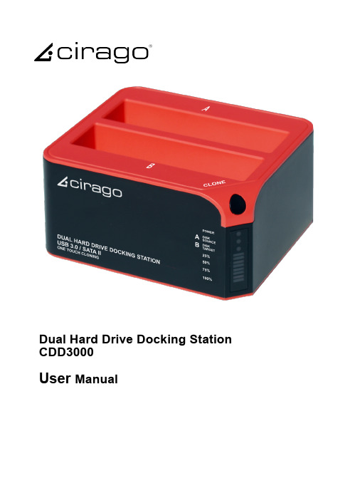
Dual Hard Drive Docking Station CDD3000User ManualIntroductionCDD3000 is a USB 3.0 dual-SATA 2.0 hard drive docking station. It supports simultaneous use of two 2.5” or 3.5” SATA hard disks for both data read and data write. It is also backward compatible with USB 2.0 and USB 1.1. It features One Touch Cloning, which clones your hard drive with touch of a button. One Touch Cloning copies data and system files from Source HDD to Target HDD, so if your Source HDD is bootable, so will your Target HDD.1) Power indicator 2) Slot ‘A’ indicator 3) Slot ‘B’ indicator 4) Clone processing indicator 5) Clone button 6) Slot ‘B’ 7) Slot ‘A’ 8) USB 3.0 input 9) Power switch (ON/OFF) 10) DC inputNote:When using E-SATA interface, the PC can only recognize one HDD in the docking station. If two HDDs are in the docking station, only Slot ‘A’ HDD will be recognized by the PC. If only one HDD is inserted to the dock, then you may use either Slot ’A’ or Slot ’B’.Function:•Complies with Gen2i/Gen2m of Serial ATA II Electrical Specification 2.6•Supports SATA II Asynchronous Signal Recovery (Hot Plug) feature•Supports SATA to SATA pass through•Complies with USB 3.0 Specification, USB Mass Storage Class, Bulk-Only Transport Specification•Supports USB Super-Speed/High-Speed/Full-Speed Operation •Supports USB HID operation•Supports USB2.0/USB3.0/eSATA power saving mode •Supports Dual LUN for USB2.0/USB3.0•One Touch Cloning•Easy to Install and Set-up•Design for Windows 2000/XP/Vista/7, Mac OS X or later version.CLONE:Please note the below conditions before clone:-Slot ‘A’ = SOURCE HDD-Slot ‘B’ = TARGET HDD-TARGET HDD’s capacity MUST be larger than SOURCE HDD, otherwise the CLONE cannot be completed. (Same capacity is also not acceptable)-Before CLONE function starts, make sure you back up any important data in TARGET HDD; once CLONE started, all data from TARGET HDD will gone.-Once the docking station is connected to the PC via USB, One Touch Cloning will not be active. See Cloning with USB section for details.1)One Touch Cloninga) Insert source HDD to Slot ‘A’; target HDD to Slot ‘B’, and then turn on the powerb)Once the Slot indicators are on, that means CDD3000 is ready for cloning.c) Press and hold the clone button for 3 seconds until the indicator light is on, press the button once more for Clone confirmation. Cloning process begins.d) Clone progress indicator flashes and shows the progress (25%, 50%, 75%, 100%).e) Once cloning is finished, all progress indicators will light up.f) Turn off power and remove the HDDs carefully2) Cloning with USBSoftware Installation (Windows only)a) Please insert the CD drive and click “setup.exe”. Chooseb) Fill in the S/N # accordingly (you can find the S/N# on the cover of CD)c) Click “Install” to begin installationd) Installation progress is displayedClone from Source HDD to Target HDDa) Insert Source HDD and Target HDD into the docking station and connect CDD3000 to PC via USB cable. Turn on the power, and you can find the clone icon on the right bottom of window. Double click the CLONE Icon to start the program.CLONE Iconb) CloneDrive activated, click “Start”c) Press start to proceed with Cloned) Clone progress is displayede) Click “OK” once clone is finishedf) You should find the same contents of Source HDD in Target HDDg) If your target HDD has extra space, the system will allocate it to “unallocated” area automatically, please refer to the below picture. Windows system only allows a maximum of fourprimary partitions, if the original disc already exist fourprimarypartitions, then it can not distinguish the extra space but logical drives can have more than oneHDD Partitiona) Open Disk management and select the unallocated areab) Right click “New partition” for further actionc) “Next”d) Base on your need and click “Next”e) Please enter the new partition capacity and click “Next” for further actionf) Assign the drive letter and “Next”g) Select “Quick Format” to format the new partitionh) Click “Finish”i) m Partition completed, the new partition can be found.Limited WarrantyThis is to certify that this Product is free of congenital defects in materials and workmanship. Cirago’s Limited warranty provides the customer 1-year free service with the following conditions:1. Warranty service is valid only in the United States and only applies to Cirago Products.2. If you are having trouble with a product, before seeking limited warranty service, first following the troubleshooting procedures that Cirago or your reseller provides.Visit to download product drivers and troubleshooting instructions.3. If you are unable to correct the problem after following the troubleshooting instructions, please call the Cirago service hotline at 408-331-8824. Have your product’s serial number and your date of purchase available when you make the call to expedite service.4. If the problem cannot be corrected over the telephone, you must take the Product, or deliver the Product freight prepaid, in either its original packaging or packaging affording an equal degree of protection to Cirago’s service center together with a copy of your dated proof of purchase, a complete explanation of the problem and a return address. Do not include other items with the defective Product.5. Any Product received by Cirago's service center that is not covered by the limited warranty will be returned unrepaired.6. We are responsible for repairing or replacing parts that are considered manufacturing defects or damaged under normal user behavior by our technicians. These parts will be free of charge within the 1-year warranty period from the date of purchase.7. All damaged parts will become Cirago’s property.8. Free warranty service will not be provided if:i) The Product has been explicitly or implicitly modified, tampered with, altered or repaired in any way by persons other than our technicians or approved vendors; orii) The Product has been damaged due to misuse, negligence, accident, shipment, inserts or natural calamities; or iii) The Product has been installed, maintained or operated not in accordance with the instructions furnished by Cirago; or iv) Any damage, deterioration or malfunction is caused by power interruption or abnormal voltage input.9. Warranty will only be valid if the date of purchase on the warranty card corresponds with that of the official purchase receipt.10. The warranty card should be properly completed and mailed back to the address indicated within 14 Days of purchase.11. The original purchase receipt shall be provided upon request for service.12. Under no circumstances will Cirago be liable for any consequential damages caused in relation to the use of this product.13. This warranty gives you specific legal rights, and you may have other rights which vary from state to state.For your convenience, Cirago has established a service hotline for frequently asked questions and service assistance or resolution of a service problem, or for product information or operation:Cirago Service CenterAddress: 611 Vaqueros Ave., Sunnyvale, CA 94085Service : 408-331-8824。
BS-3000说明书1
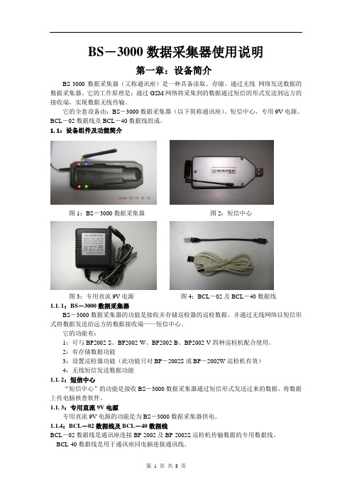
BS-3000数据采集器使用说明第一章:设备简介BS-3000数据采集器(又称通讯座)是一种具备读取、存储、通过无线网络发送数据的数据采集器。
它的工作原理是:通过GSM网络将采集到的数据通过短信的形式发送到远方的接收端,实现数据无线传输。
它的全套设备由:BS-3000数据采集器(以下简称通讯座)、短信中心、专用9V电源、BCL-02数据线及BCL-40数据线组成。
1.1:设备组件及功能简介图1:BS-3000数据采集器图2:短信中心图3:专用直流9V电源图4:BCL-02及BCL-40数据线1.1.1:BS-3000数据采集器BS-3000数据采集器的功能是接收并存储巡检器的巡检数据,并通过无线网络以短信形式将数据发送给远方的数据接收端——短信中心。
它的功能有:1:可与BP2002-S、BP2002-W、BP2002-B、BP2002-V四种巡检机配合使用。
2:有存储数据功能3:设置巡检器功能(此功能只对BP-2002S或BP-2002W巡检机有效)4:无线短信发送数据功能1.1.2:短信中心“短信中心”的功能是接收BS-3000数据采集器通过短信形式发送过来的数据,将数据上传电脑核查软件。
1.1.3:专用直流9V电源专用直流9V电源的功能是为BS-3000数据采集器供电。
1.1.4:BCL-02数据线及BCL-40数据线BCL-02数据线是通讯座连接BP-2002及BP-2002S巡检机传输数据的专用数据线。
BCL-40数据线是用于通讯座同电脑连接通讯线。
第二章:设备参数2.1通讯座相关参数体积(长×宽×高)157mm×77.5mm×31mm质量(g)164g供电方式(三种)1:直流9V电源供电2:USB接口供电3:3.6V锂电电池供电存储介质Flash、掉电保存存储容量49713条记录读卡类型EMID 射频格式工作温度-20℃~70℃工作湿度0~95%2.2:设备指示灯简介2.2.1:数据指示灯闪烁:表示通讯座正在接收/发送数据常亮:表示通讯座内有未上传的数据熄灭:表示通讯座内无未上传数据2.2.2:与电脑通讯状态指示灯/低电压报警闪烁频率1次/秒表示正常工作长亮或长灭:表示工作异常。
HT-IDE3000 Holtek C语言编程指南(中文)
语言的程序结构 C
......................................................................................2
语句 ......................................................................................................2
注释 ......................................................................................................2
标识符..........................................................................................................3
逻辑运算符 ..........................................................................................8
位运算符 ..............................................................................................8
常量 ....................................................................................................28
HT-IDE3000 Holtek C 语言 编程指南 Ver 1.1
Transition Networks产品目录:传输设备、扩展器、NIDs说明书
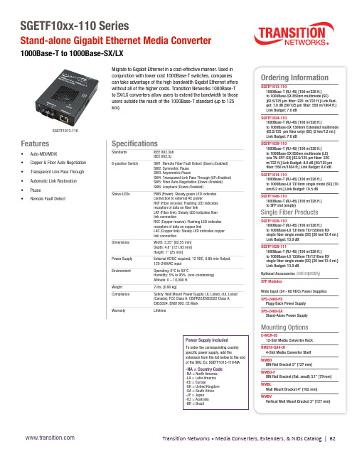
Transition Networks • Media Converters, Extenders, & NIDs Catalog | 62Power Supply Included To order the corresponding country specific power supply, add the extension from the list below to the end of the SKU; Ex: SGETF1013-110-NA -NA = Country Code -NA = North America -LA = Latin America -EU = Europe -UK = United Kingdom -SA = South Africa -JP = Japan -OZ = Australia -BR = Brazil Specifications Standards IEEE 802.3ab IEEE 802.3z 6-position Switch SW1: Remote Fiber Fault Detect (Down=Enabled) SW2: Symmetric Pause SW3: Asymmetric Pause SW4: Transparent Link Pass Through (UP=Enabled) SW5: Fiber Auto-Negotiation (Down=Enabled) SW6: Loopback (Down=Enabled)Status LEDs PWR (Power): Steady green LED indicates connection to external AC power RXF (Fiber receive): Flashing LED indicates reception of data on fiber link LKF (Fiber link): Steady LED indicates fiber link connection RXC (Copper receive): Flashing LED indicates reception of data on copper link LKC (Copper link): Steady LED indicates copper link connection Dimensions Width: 3.25” [82.55 mm] Depth: 4.8” [121.92 mm] Height: 1" [25 mm]Power Supply External AC/DC required; 12 VDC, 0.8A min Output; 120-240VAC input Environment Operating: 0°C to 50°C Humidity: 5% to 95% (non-condensing) Altitude: 0 – 10,000 ft. Weight 2 lbs. [0.90 kg]Compliance Safety: Wall Mount Power Supply: UL Listed, cUL Listed (Canada); FCC Class A, CISPR22/EN55022 Class A, EN55024, EN61000, CE Mark Warranty Lifetime Migrate to Gigabit Ethernet in a cost-effective manner. Used in conjunction with lower cost 1000Base-T switches, companies can take advantage of the high bandwidth Gigabit Ethernet offers without all of the higher costs. Transition Networks 1000Base-T to SX/LX converters allow users to extend the bandwidth to thoseusers outside the reach of the 1000Base-T standard (up to 125 km).Features• Auto-MDI/MDIX• Copper & Fiber Auto-Negotiation• Transparent Link Pass Through• Automatic Link Restoration• Pause• Remote Fault DetectSGETF10xx-110 SeriesStand-alone Gigabit Ethernet Media Converter 1000Base-T to 1000Base-SX/LXOrdering Information SGETF1013-110 1000Base-T (RJ-45) [100 m/328 ft.] to 1000Base-SX 850nm multimode (SC) [62.5/125 µm fiber: 220 m/722 ft.] Link Bud-get: 7.0 dB [50/125 µm fiber: 550 m/1804 ft.] Link Budget: 7.0 dB SGETF1024-110 1000Base-T (RJ-45) [100 m/328 ft.] to 1000Base-SX 1300nm Extended multimode (62.5/125 µm fiber only) (SC) [2 km/1.2 mi.] Link Budget: 7.0 dB SGETF1039-110 1000Base-T (RJ-45) [100 m/328 ft.] to 1000Base-SX 850nm multimode (LC) (via TN-SFP-SX) [62.5/125 µm fiber: 220 m/722 ft.] Link Budget: 8.0 dB [50/125 µm fiber: 550 m/1804 ft.] Link Budget: 8.0 dB SGETF1014-110 1000Base-T (RJ-45) [100 m/328 ft.] to 1000Base-LX 1310nm single mode (SC) [10 km/6.2 mi.] Link Budget: 10.5 dB SGETF1040-110 1000Base-T (RJ-45) [100 m/328 ft.] to SFP slot (empty)Single Fiber Products SGETF1029-110 1000Base-T (RJ-45) [100 m/328 ft.] to 1000Base-LX 1310nm TX/1550nm RX single fiber single mode (SC) [20 km/12.4 mi.] Link Budget: 13.0 dB SGETF1029-111 1000Base-T (RJ-45) [100 m/328 ft.] to 1000Base-LX 1550nm TX/1310nm RX single fiber single mode (SC) [20 km/12.4 mi.] Link Budget: 13.0 dB Optional Accessories (sold separately)SFP Modules Wide Input (24 - 60 VDC) Power Supplies SPS-2460-PS Piggy Back Power Supply SPS-2460-SA Stand-Alone Power Supply Mounting Options E-MCR-05 12-Slot Media Converter Rack RMS19-SA4-01 4-Slot Media Converter Shelf WMBD DIN Rail Bracket 5" [127 mm]WMBD-F DIN Rail Bracket (flat, small) 3.1” [79 mm]WMBL Wall Mount Bracket 4" [102 mm]WMBV Vertical Wall Mount Bracket 5" [127 mm]SGETF1013-110。
带 Microsoft Windows Server 故障转移群集的 Dell PowerVault
带 Microsoft ® Windows Server ® 故障转移群集的 Dell™ PowerVault™ MD3000 存储阵列硬件安装与故障排除指南简介群集硬件的布线准备用于群集的系统故障排除群集数据表注、注意和警告本说明文件中的信息如有更改,恕不另行通知。
© 2008 Dell Inc. 版权所有,翻印必究。
未经 Dell Inc. 书面许可,严禁以任何形式进行复制。
本文中使用的商标:Dell 、DELL 徽标、PowerEdge 、 PowerVault 和 OpenManage 是 Dell Inc. 的商标;Microsoft 、SQL Server 、Windows 、 和 Windows NT 是 Microsoft Corporation 在美国和/或其它国家和地区的商标或注册商标。
本文中述及的其它商标和产品名称是指拥有相应商标和产品名称的公司或其制造的产品。
Dell Inc. 对本公司的商标和产品名称之外的其它商标和产品名称不拥有任何专有权。
2008 年 4 月 修订版 A00注: "注"表示可以帮助您更好地使用计算机的重要信息。
注意: "注意"表示可能会损坏硬件或导致数据丢失,并告诉您如何避免此类问题。
警告: "警告"表示可能会导致财产损失、人身伤害甚至死亡。
返回目录页面群集硬件的布线带Microsoft ® Windows Server ® 故障转移群集的 Dell™ PowerVault™ MD3000 存储阵列硬件安装与故障排除指南鼠标、键盘和显示器的布线电源设备的布线公用网络和专用网络的布线存储系统的布线以下部分将帮助您将电源、网络和存储电缆连接至群集。
连接硬件组件后,本文档中的后续部分将向您提供配置群集的说明。
鼠标、键盘和显示器的布线在机架中安装群集配置时,必须安装切换器盒,以将鼠标、键盘和显示器连接至节点。
MD-3000系统实验教材
MD3000生物信号采集系统高校教材安徽正华生物仪器设备有限公司目录一、前言 (3)二、MD3000系统介绍 .................................................................................................... 3-4(一)系统组成与基本工作原理 (3)(三)系统应用软件简介 (5)三、MD3000系统软件使用说明..................................................................................... 7-27四、MD3000在典型生理学实验中的应用介绍........................................................... 30-29实验一、神经干动作电位的引导实验........................................................................ 30-28实验二、动物动脉血压、心电及呼吸的记录、实验................................................ 30-29五、系统使用问题及解决方法 (32)六、实验案例……………………………………………………………………………………………30-116(实验一)蟾蜍坐骨神经腓肠肌标本制备……………………………..…………………………………30-33(实验二)不同刺激强度和频率对骨骼肌收缩的影响………………………………………………….34-38(实验三)骨骼肌兴奋时电活动与收缩的关系…………………………………………………………...38-41(实验四)神经干动作电位及其传导速度的测定……………………………………………………….41-45(实验五)神经兴奋不应期的测定……………………………………………………………………….45-47(实验六)神经-肌肉接头兴奋的传递和阻滞…………………………………………………………..47-49(实验七)红细胞渗透脆性测定………………………………………………………………………….49-51(实验八)出血时间和凝血时间的测定………………………………………………………………….51-52(实验九)影响血液凝固的因素………………………………………………………………………….53-55(实验十)ABO血型的测定……………………………………………………………………………….55-56(实验十一)心室期前收缩与代偿间歇及不应期的测定……………………………………………..56-60(实验十二)离体蛙心灌流……………………………………………………………………………..61-65(实验十三)容积导体的心电描记………………………………………………………………………65-67(实验十四)离体心脏冠脉流量和心脏收缩活动测定…………………………………………………68-72(实验十五)心脏听诊和人体动脉血压测定 (73)(实验十六)人体心电图描记…………………………………………………………………………….73-74(实验十七)动脉血压的神经、体液调节……………………………………………………………….74-78(实验十八)降压神经放电……………………………………………………………………………….78-81(实验十九)左心室内压的测定…………………………………………………………………………81-84(实验二十)肠系膜微循环观察………………………………………………………………………..84-86(实验二十一)呼吸运动的调节………………………………………………………………………..86-89(实验二十二)胸内负压的观察………………………………………………………………………..89-91(实验二十三)肺通气功能的测定……………………………………………………………………..91-94(实验二十四)膈神经放电……………………………………………………………………………..94-97(实验二十五)胰液和胆汁分泌的调节…………………………………………………………………97-100(实验二十六)离体小肠平滑肌运动………………………………………………………………..100-104(实验二十七)胃肠运动观察…………………………………………………………………………104-106(实验二十八)尿生成的影响因素…………………………………………………………………..106-109(实验二十九)大脑皮质诱发电位…………………………………………………………………….110-113(实验三十)耳蜗微音器电位…………………………………………………………………………113-116一、前言MD3000生物信号采集处理系统,是集众多专家、教授多年研制PC机生物信号采集处理系统经验而推出的又一高科技产品,可取代传统的记录仪、示波器和刺激器等实验仪器,应用于大中专院校的生理学、药理学和病理生理学等方面的教学与科研实验。
MDO3000 系列示波器产品技术资料
混合域示波器 - MDO3000 系列
带有 FastAcq 的数字荧光技术可以实现 > 280,000 wfm/s 的波形捕 获速率和实时颜色辉度等级。
触发 发现设备问题只是第一步,然后,您必须捕获关心的事件, 以确定根本原因。为了实现这一目标,MDO3000 系列含有 超过 125 种触发组合,提供了一套完整的触发功能,包括欠 幅脉冲触发、逻辑触发、脉宽 / 毛刺触发、建立时间 / 保持时 间违规触发、串行数据包触发和并行数据触发,帮助您迅速 找到关心的事件。由于具有高达 10 M 点的记录长度,您可 以在一次采集中捕获许多关心的事件,甚至包括数千个串行 数据包,以进一步进行分析,同时保持高分辨率,以放大观 察精细的信号细节。
自动测量读数提供了可重复的波形特点统计视图。
搜索步骤 2:Wave Inspector 自动搜索和记录每个事件,并用空心 白三角标记事件。然后可以使用 Previous 和 Next 按钮,从一个事件 跳到下一个事件。
每种测量均有帮助文本以及相关图形,帮助解释如何进行测量。
搜索步骤 3:搜索标记 (Search Mark) 表以表格视图呈现了通过自动 搜索所发现的每个事件。每个事件都显示有一个时间戳,在事件之 间方便地进行定时测量。
这些调色板可以迅速突出显示发生频次高的事件,在偶发异 常事件中,则会突出显示发生频次低的事件。
您可以选择无限余辉或可变余辉,确定波形在屏幕上停留多 长时间,进而可以确定异常事件的发生频次。
►► 3 GHz 和 6 GHz 集成频谱分析仪 ►► 同时采集模拟信号、数字信号和射频信号 ►► 20 M 记录长度 ►► 10.4 英寸 XGA 显示器
缩放和卷动
这个专用的两层前面板控件为缩放和卷动提供直观的控制。 内环控件调节缩放系数 ( 或缩放比例 ),顺时针旋转将激活缩 放并逐渐增大缩放系数,逆时针旋转将减小缩放系数,最终 可关闭缩放。您无需再去通过几个菜单来完成缩放显示。外 环控件在波形中卷动缩放框,以快速到达所关心的波形部分, 同时还利用力反馈来确定在波形中卷动的速度。外环控件旋 转得越快,缩放框移动得越快。只需向相反方向转动即可改 变卷动的方向。
Tektronix MDO3000 Series Oscilloscope Safety Guide

Contacting TektronixTektronix,Inc.,14150SW Karl Braun Drive,P.O.Box 500,Beaverton,OR 97077,USAFor product information,sales,service,and technical support:In North America,call 1-800-833-9200.Worldwide,visit to find contacts in your area.General safety summaryUse the product only as speci fied.Review the following safety precautions to avoid injury and prevent damage to this product or any products connected to it.Carefully read all instructions.Retain these instructions for future ply with local and national safety codes.For correct and safe operation of the product,it is essential that you follow generally accepted safety procedures in addition to the safety precautions speci fied in this manual.The product is designed to be used by trained personnel only.Only quali fied personnel who are aware of the hazards involved should remove the cover for repair,maintenance,or adjustment.To avoid fire or personal injuryUse proper power e only the power cord speci fied for this product and certi fied for the country of use.Do not use the provided power cord for other products.Ground the product.This product is grounded through the grounding conductor of the power cord.To avoid electric shock,the grounding conductor must be connected to earth ground.Before making connections to the input or output terminals of the product,ensure that the product is properly grounded.Do not disable the power cord grounding connection.Observe all terminal ratings.To avoid fire or shock hazard,observe all ratings and markings on the product.Consult the product manual for further ratings information before making connections to the product.Do not apply a potential to any terminal,including the common terminal,that exceeds the maximum rating of that terminal.Power disconnect.The power cord disconnects the product from the power source.See instructions for the location.Do not position equipment so that it is dif ficult to disconnect the power cord;it must remain accessible to the user at all times to allow for quick disconnection if needed.Connect and disconnect properly.Do not connect or disconnect probes or test leads while they are connected to a voltage source.Use only insulated voltage probes,test leads,and adapters supplied with the product,or indicated by Tektronix to be suitable for the product.Do not float the common terminal above the rated voltage for that terminal.Do not operate without covers.Do not operate this product with covers or panels removed.Avoid exposed circuitry.Do not touch exposed connections and components when power is present.Do not operate with suspected failures.If you suspect that there is damage to this product,have it inspected by quali fied service personnel.Disable the product if it is damaged.Do not use the product if it is damaged or operates incorrectly.If in doubt about safety of the product,turn it off and disconnect the power cord.Clearly mark the product to prevent its further operation.Before use,inspect voltage probes,test leads,and accessories for mechanical damage and replace when damaged.Do not use probes or test leads if they are damaged,if there is exposed metal,or if a wear indicator shows.Examine the exterior of the product before you use it.Look for cracks or missing e only speci fied replacement parts.Do not operate in wet/damp conditions.Be aware that condensation may occur if a unit is moved from a cold to a warm environment.Do not operate in an explosive atmosphere.Provide proper ventilation.Refer to the installation instructions for details on installing the product so it has proper ventilation.Slots and openings are provided for ventilation and should never be covered or otherwise obstructed.Do not push objects into any of the openings.Provide a safe working environment.Always place the product in a location convenient for viewing the display and e care when lifting and carrying the product.This product is provided with handles for lifting and carrying.Use only the Tektronix rackmount hardware speci fied for this product.Keep product surfaces clean and dry.Remove the input signals before you clean the product.Inspect the instrument as often as operating conditions require.To clean the exterior surface,perform the following steps:1.Remove loose dust on the outside of the instrument with a lint-free e care to avoid scratching the clear glass display filter.2.Use a soft cloth dampened with water to clean the e an aqueous solution of 75%isopropyl alcohol for more ef ficientcleaning.CAUTION.Avoid getting moisture inside the unit during external e only enough cleaning solution to dampen the cloth or swab.To avoid damage to the instrument,do not expose it to sprays,liquids,or solvents,and do not use any abrasive or chemical cleaning agents.Service safety summaryThe Service safety summary section contains additionalinformation required to safely perform service on the product.Only quali fied personnel should perform service procedures.Read this Service safety summary and the General safety summary before performing any service procedures.To avoid electric shock.Do not touch exposed connections.Do not touch exposed connections..Do not perform internal service or adjustments of this product unless another person capable of rendering first aid and resuscitation is present.Disconnect power.To avoid electric shock,switch off the product power and disconnect the power cord from the mains power before removing any covers or panels,or opening the case for servicing.Use care when servicing with power on.Dangerous voltages or currents may exist in this product.Disconnect power,remove battery (if applicable),and disconnect test leads before removing protective panels,soldering,or replacing components.Verify safety after repair.Always recheck ground continuity and mains dielectric strength after performing a repair.Terms in this manualThese terms may appear in thismanual:WARNING.Warning statements identify conditions or practices that could result in injury or loss oflife.CAUTION.Caution statements identify conditions or practices that could result in damage to this product or other property.Symbols and terms on the productThese terms may appear on the product:DANGER indicates an injury hazard immediately accessible as you read the marking.WARNING indicates an injury hazard not immediately accessible as you read the marking.CAUTION indicates a hazard to property including the product.The following symbol(s)may appear on theproduct:Compliance informationThis section lists the EMC (electromagnetic compliance),safety,and environmental standards with which the instrument complies.EMC complianceEC Declaration of Conformity –EMCMeets intent of Directive 2004/108/EC for Electromagnetic pliance was demonstrated to the following speci fications as listed in the Of ficial Journal of the European Communities:EN 61326-1:2006.EMC requirements for electrical equipment for measurement,control,and laboratory use.123CISPR 11:2003.Radiated and conducted emissions,Group 1,Class AIEC 61000-4-2:2001.Electrostatic discharge immunity IEC 61000-4-3:2002.RF electromagnetic field immunity IEC 61000-4-4:2004.Electrical fast transient/burst immunityIEC 61000-4-5:2001.Power line surge immunity IEC 61000-4-6:2003.Conducted RF immunity IEC 61000-4-11:2004.V oltage dips and interruptions immunityEN 61000-3-2:2006.AC power line harmonic emissions EN 61000-3-3:1995.Voltage changes,fluctuations,and flicker European contact.Tektronix UK,Ltd.Western Peninsula Western RoadBracknell,RG121RF United Kingdom1This product is intended for use in nonresidential areas e in residential areas may cause electromagnetic interference.2Emissions which exceed the levels required by this standard may occur when this equipment is connected to a test object.3To ensure compliance with the EMC standards listed here,high quality shielded interface cables should be used.Australia /New Zealand Declaration of Conformity –EMCComplies with the EMC provision of the Radiocommunications Act per the following standard,in accordance with ACMA:CISPR 11:2003.Radiated and Conducted Emissions,Group 1,Class A,in accordance with EN 61326-1:2006.Australia/New Zealand contact.Baker &Mckenzie Level 27,AMP Centre 50Bridge Street Sydney NSW 2000AustraliaSafety complianceEU Declaration of Conformity –Low VoltageCompliance was demonstrated to the following speci fication as listed in the Of ficial Journal of the European Union:Low V oltage Directive 2006/95/EC.EN 61010-1.Safety requirements for electrical equipment for measurement,control,and laboratory use –Part 1:General Requirements.U.S.nationally recognized testing laboratory listingUL 61010-1.Safety requirements for electrical equipment for measurement,control,and laboratory use –Part 1:General Requirements.Canadian certi ficationCAN/CSA-C22.2No.61010-1.Safety requirements for electrical equipment for measurement,control,and laboratory use –Part 1:General Requirements.Additional compliancesIEC 61010-1.Safety requirements for electrical equipment for measurement,control,and laboratory use –Part 1:General Requirements.Equipment typeTest and measuring equipment.Safety classClass 1–grounded product.AFG3000C Series Generators Compliance and Safety Instructions1*P071324400*071-3244-00Pollution degree descriptionA measure of the contaminants that could occur in the environment around and within a product.Typically the internal environment inside a product is considered to be the same as the external.Products should be used only in the environment for which they are rated.Pollution Degree1.No pollution or only dry,nonconductive pollution occurs.Products in this category are generally encapsulated,hermetically sealed,or located in clean rooms.Pollution Degree2.Normally only dry,nonconductivepollution occurs.Occasionally a temporary conductivitythat is caused by condensation must be expected.Thislocation is a typical office/home environment.Temporary condensation occurs only when the product is out ofservice.Pollution Degree3.Conductive pollution,or dry,nonconductive pollution that becomes conductive dueto condensation.These are sheltered locations whereneither temperature nor humidity is controlled.The area is protected from direct sunshine,rain,or direct wind.Pollution Degree4.Pollution that generates persistentconductivity through conductive dust,rain,or snow.Typical outdoor locations.Pollution degree ratingPollution Degree2(as defined in IEC61010-1).Rated for indoor,dry location use only.IP ratingIP20(as defined in IEC60529).Measurement and overvoltage category descriptions Measurement terminals on this product may be rated for measuring mains voltages from one or more of the following categories(see specific ratings marked on the product and in the manual).Category II.Circuits directly connected to the buildingwiring at utilizationpoints(socket outlets and similar points).Category III.In the building wiring and distributionsystem.Category IV.At the source of the electrical supply to the building.NOTE.Only mains power supply circuits have an overvoltage category rating.Only measurement circuits have a measurement category rating.Other circuits within the product do not have either rating.Mains overvoltage category ratingOvervoltage Category II(as defined in IEC61010-1).Environmental considerationsRefer to the Quick Start User Manual for information about the environmental impact of the product.Operating overviewThis document contains information for the followingAFG3000C Series Arbitrary Function Generator products. Refer to the Quick Start User Manual and Specifications and Performance Verification Technical Reference for complete operating information and product specifications.AFG3011C,AFG3021C,AFG3101C,AFG3102C,AFG3022C,AFG3051C,AFG3052C,AFG3251C,AFG3252CPower sourceThis generator operates from a single-phase power source with the neutral conductor at or near earth ground.It is intended for only ground-referenced measurements.A protective ground connection through the grounding conductor in the power cord is essential for safe operation.Power the unit on by connecting the supplied power cord to the rear-panel power connector(1).Push the power button(2)on the front of the instrument to turn it on.To power the unit off,push the power button on the front of the instrument again.Toremove power completely,disconnect the power cord from therear-panel of theinstrument.WARNING.To reduce the risk offire and shock,ensure thatthe mains supply voltagefluctuations do not exceed10%ofthe operating voltagerange.Power specifications and clearance requirementsCharacteristic DescriptionSource voltage and frequency100V to240V,47Hzto63Hz115V,360to440HzPower consumption Less than120WPlace the instrument on a cart or bench,observing the followingclearance requirements.Before operating,ensure that theambient temperature is between0°C to+50°C(+32°F to+122°F).Sides:50mm(2in)Rear:50mm(2in)CAUTION.To ensure proper cooling,keep both sides of theinstrument clear ofobstructions.Environmental specificationsCharacteristic DescriptionTemperature rangeOperating0°C to+50°CNon operating-30°C to+70°CHumidityOperating(non condensing)0°C to+40°C:≤80%+40°C to+50°C:≤60%Non operating(non condensing)<+40°C:5%to90%≥+40°C to≤+60°C:5%to80%>+60°C to≤+70°C:5%to40%AltitudeOperating Up to3,000meters(9,843feet)Non operating Up to12,000meters(39,370feet)Front panel controlsThe front panel is divided into easy-to-use functional areas.The followingfigure shows a dual-channelmodel.1.Bezel menu buttons2.Top menu button3.Function buttons4.Shortcut buttons5.Numeric keypad6.Triggered LED is lit when the instrument receives aninternal or external trigger7.Trigger input connector8.Trigger output connector9.Menu buttons10.CH1and CH2output connectors11.Return to previous menu button12.View buttonB connector14.Power on/off switchScreeninterface1.Output status:If the output is set to disable,Output Offmessage is displayed in this area.When you push thefront panel channel output button to enable the output,the message will disappear.2.Bezel menu:When you push a front panel button,theinstrument displays the corresponding menu on the rightside of the screen.The menu shows the options that areavailable when you push the unlabeled bezel buttonsdirectly to the right of the screen.3.Message display area:A message that monitors hardwarestatus such as clock or trigger is displayed in this area.4.Level meter:Amplitude level is displayed.5.Main display area and View tab:Pushing the front-panelView button toggles through the view format of the maindisplay area.The view tabs correspond with the currentview format.The instrument can display three differentscreen formats.Copyright©Tektronix,Inc.All rights Tektronix 联系信息Tektronix,Inc.,14150SW Karl Braun Drive,P.O.Box 500,Beaverton,OR 97077,USA有关产品信息、销售、服务和技术支持:在北美地区,请拨打1-800-833-9200。
101种混合域示波器实战技巧
电源
MDO3PWR 功率分析软件包。 46. 对比电源线谐波和法规极限 47. 确认 MOSFET 位于安全作业区内 48. 测量纹波 49. 测量涌入电流 50. 检查变化负载下的稳压情况 51. 捕获功率瞬态信号 52. 确认电压电平 53. 检定功率峰数校正 54. 测量波峰因数 55. 量化开关损耗 56. 检查最小和最大工频电压 57. 测量待机电流 58. 检查逆电器上的相位关系
MDO3000 系列混合域示波器的 101 种用途 处理器系统
1. 检查开机时间 2. 解码 SPI 业务,查看信号质量 3. 查看开机期间的时钟及第一次 I2C 业务 4. 检查并行总线定时 5. 测量相邻引脚上的串扰 6. 测量 I2C 和 USB2.0 总线数据之间的定时 7. 触发 FPGA 上的欠幅脉冲 8. 触发建立时间 / 保持时间违规 9. 测量程序执行时间 10. 触发缓慢上升时间 11. 触发缓慢下降时间 12. 在监视计时器到时时,捕获 SPI 总线和电源状态 13. 诊断地电平弹跳 14. 检查引脚到引脚总线定时变化 15. 测量中断响应时间 16. 查找并行总线上的争用情况来源 17. 测量差分信号
MDO3000 系列混合域示波器的 101 种用途
六台仪器合一
MDO3000 覆盖了您的大多数日常需求,同时融合下述仪器的功能: 行业领先的示波器 频谱分析仪 任意波形 / 函数发生器 逻辑分析仪 协议分析仪 数字电压表和频率计数器 通过融合示波器和频谱分析仪的功能,混合域示波器可以使用一台仪器,同 时 在 时 域 和 频 域 中 工 作。 毫 无 疑 问, 一 旦 到 位, 您 可 以 通 过 各 种 方 式 使 用 MDO3000,而下面则列出了您可以考虑完成的 101 项任务。
