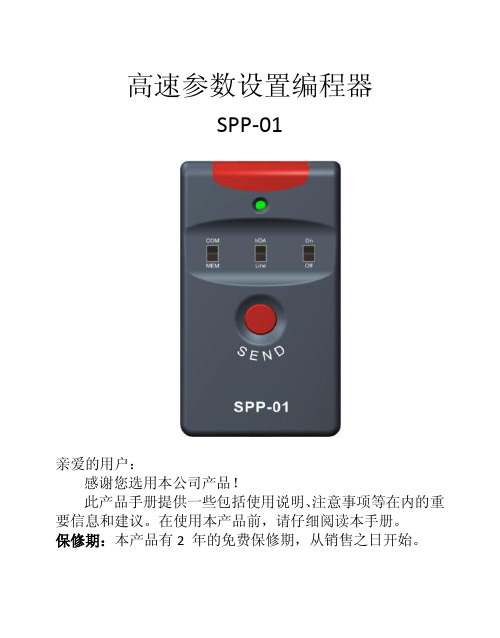
SP40编程器使用手册 V1.00
SP16系列编程器使用手册说明书

SP16系列编程器使用手册Revision B5使用编程器之前,请仔细阅读本手册,并按要求正确操作编程器,不按要求操作 将会导致编程器损坏,并得不到保修服务!深圳硕飞科技有限公司SHENZHEN SOFI TECHNOLOGY CO.,LTD .WEB: 硕飞科技目录第一章产品介绍∙∙∙∙∙∙∙∙∙∙∙∙∙∙∙∙∙∙∙∙∙∙∙∙∙∙∙∙∙∙∙∙∙∙∙∙∙∙∙∙∙∙∙∙∙∙∙∙∙∙∙∙∙∙∙∙∙∙∙∙∙∙∙∙∙∙∙∙∙∙∙∙∙∙∙∙∙∙∙∙∙∙∙∙∙∙∙∙∙∙∙∙∙∙∙∙∙∙∙∙∙∙∙∙∙∙∙∙∙∙∙∙∙∙∙∙∙∙∙∙∙3 功能特点∙∙∙∙∙∙∙∙∙∙∙∙∙∙∙∙∙∙∙∙∙∙∙∙∙∙∙∙∙∙∙∙∙∙∙∙∙∙∙∙∙∙∙∙∙∙∙∙∙∙∙∙∙∙∙∙∙∙∙∙∙∙∙∙∙∙∙∙∙∙∙∙∙∙∙∙∙∙∙∙∙∙∙∙∙∙∙∙∙∙∙∙∙∙∙∙∙∙∙∙∙∙∙∙∙∙∙∙∙∙∙∙∙∙∙∙∙∙∙∙∙3 SP16系列编程器功能对比表∙∙∙∙∙∙∙∙∙∙∙∙∙∙∙∙∙∙∙∙∙∙∙∙∙∙∙∙∙∙∙∙∙∙∙∙∙∙∙∙∙∙∙∙∙∙∙∙∙∙∙∙∙∙∙∙∙∙∙∙∙∙∙∙∙∙∙∙∙∙∙∙∙∙∙∙∙∙∙∙∙∙∙∙∙∙∙∙∙∙∙∙∙ 4 第二章编程器硬件∙∙∙∙∙∙∙∙∙∙∙∙∙∙∙∙∙∙∙∙∙∙∙∙∙∙∙∙∙∙∙∙∙∙∙∙∙∙∙∙∙∙∙∙∙∙∙∙∙∙∙∙∙∙∙∙∙∙∙∙∙∙∙∙∙∙∙∙∙∙∙∙∙∙∙∙∙∙∙∙∙∙∙∙∙∙∙∙∙∙∙∙∙∙∙∙∙∙∙∙∙∙∙∙∙∙∙∙∙∙∙∙∙∙∙∙∙∙5 第三章快速使用∙∙∙∙∙∙∙∙∙∙∙∙∙∙∙∙∙∙∙∙∙∙∙∙∙∙∙∙∙∙∙∙∙∙∙∙∙∙∙∙∙∙∙∙∙∙∙∙∙∙∙∙∙∙∙∙∙∙∙∙∙∙∙∙∙∙∙∙∙∙∙∙∙∙∙∙∙∙∙∙∙∙∙∙∙∙∙∙∙∙∙∙∙∙∙∙∙∙∙∙∙∙∙∙∙∙∙∙∙∙∙∙∙∙∙∙∙∙∙∙∙6 联机模式烧录步骤∙∙∙∙∙∙∙∙∙∙∙∙∙∙∙∙∙∙∙∙∙∙∙∙∙∙∙∙∙∙∙∙∙∙∙∙∙∙∙∙∙∙∙∙∙∙∙∙∙∙∙∙∙∙∙∙∙∙∙∙∙∙∙∙∙∙∙∙∙∙∙∙∙∙∙∙∙∙∙∙∙∙∙∙∙∙∙∙∙∙∙∙∙∙∙∙∙∙∙∙∙∙∙∙∙∙∙ 6 联机烧录模式指示灯状态说明∙∙∙∙∙∙∙∙∙∙∙∙∙∙∙∙∙∙∙∙∙∙∙.∙∙∙∙∙∙∙∙∙∙∙∙∙∙∙∙∙∙∙∙∙∙∙∙∙∙∙∙∙∙∙∙∙∙∙∙∙∙∙∙∙∙∙∙∙∙∙∙∙∙∙∙∙∙∙∙∙∙∙∙∙∙∙∙∙∙∙8 第四章脱机烧录∙∙∙∙∙∙∙∙∙∙∙∙∙∙∙∙∙∙∙∙∙∙∙∙∙∙∙∙∙∙∙∙∙∙∙∙∙∙∙∙∙∙∙∙∙∙∙∙∙∙∙∙∙∙∙∙∙∙∙∙∙∙∙∙∙∙∙∙∙∙∙∙∙∙∙∙∙∙∙∙∙∙∙∙∙∙∙∙∙∙∙∙∙∙∙∙∙∙∙∙∙∙∙∙∙∙∙∙∙∙∙∙∙∙∙∙∙∙∙∙∙9 下载脱机数据∙∙∙∙∙∙∙∙∙∙∙∙∙∙∙∙∙∙∙∙∙∙∙∙∙∙∙∙∙∙∙∙∙∙∙∙∙∙∙∙∙∙∙∙∙∙∙∙∙∙∙∙∙∙∙∙∙∙∙∙∙∙∙∙∙∙∙∙∙∙∙∙∙∙∙∙∙∙∙∙∙∙∙∙∙∙∙∙∙∙∙∙∙∙∙∙∙∙∙∙∙∙∙∙∙∙∙∙∙∙∙∙∙∙9 脱机运行–手动方式∙∙∙∙∙∙∙∙∙∙∙∙∙∙∙∙∙∙∙∙∙∙∙∙∙∙∙∙∙∙∙∙∙∙∙∙∙∙∙∙∙∙∙∙∙∙∙∙∙∙∙∙∙∙∙∙∙∙∙∙∙∙∙∙∙∙∙∙∙∙∙∙∙∙∙∙∙∙∙∙∙∙∙∙∙∙∙∙∙∙∙∙∙∙∙∙∙∙∙∙∙∙10 脱机运行–自动控制方式∙∙∙∙∙∙∙∙∙∙∙∙∙∙∙∙∙∙∙∙∙∙∙∙∙∙∙∙∙∙∙∙∙∙∙∙∙∙∙∙∙∙∙∙∙∙∙∙∙∙∙∙∙∙∙∙∙∙∙∙∙∙∙∙∙∙∙∙∙∙∙∙∙∙∙∙∙∙∙∙∙∙∙∙∙∙∙∙∙∙∙∙∙∙∙∙10 ATE接口定义∙∙∙∙∙∙∙∙∙∙∙∙∙∙∙∙∙∙∙∙∙∙∙∙∙∙∙∙∙∙∙∙∙∙∙∙∙∙∙∙∙∙∙∙∙∙∙∙∙∙∙∙∙∙∙∙∙∙∙∙∙∙∙∙∙∙∙∙∙∙∙∙∙∙∙∙∙∙∙∙∙∙∙∙∙∙∙∙∙∙∙∙∙∙∙∙∙∙∙∙∙∙∙∙∙∙∙∙∙∙∙∙10 脱机工作模式状态指示灯∙∙∙∙∙∙∙∙∙∙∙∙∙∙∙∙∙∙∙∙∙∙∙∙∙∙∙∙∙∙∙∙∙∙∙∙∙∙∙∙∙∙∙∙∙∙∙∙∙∙∙∙∙∙∙∙∙∙∙∙∙∙∙∙∙∙∙∙∙∙∙∙∙∙∙∙∙∙∙∙∙∙∙∙∙∙∙∙∙∙∙∙∙∙∙∙∙∙ 11 脱机数据查看∙∙∙∙∙∙∙∙∙∙∙∙∙∙∙∙∙∙∙∙∙∙∙∙∙∙∙∙∙∙∙∙∙∙∙∙∙∙∙∙∙∙∙∙∙∙∙∙∙∙∙∙∙∙∙∙∙∙∙∙∙∙∙∙∙∙∙∙∙∙∙∙∙∙∙∙∙∙∙∙∙∙∙∙∙∙∙∙∙∙∙∙∙∙∙∙∙∙∙∙∙∙∙∙∙∙∙∙∙∙∙∙∙∙∙11 第五章ISP 模式烧录∙∙∙∙∙∙∙∙∙∙∙∙∙∙∙∙∙∙∙∙∙∙∙∙∙∙∙∙∙∙∙∙∙∙∙∙∙∙∙∙∙∙∙∙∙∙∙∙∙∙∙∙∙∙∙∙∙∙∙∙∙∙∙∙∙∙∙∙∙∙∙∙∙∙∙∙∙∙∙∙∙∙∙∙∙∙∙∙∙∙∙∙∙∙∙∙∙∙∙∙∙∙∙∙∙∙∙∙∙∙∙∙∙12 ISP接口∙∙∙∙∙∙∙∙∙∙∙∙∙∙∙∙∙∙∙∙∙∙∙∙∙∙∙∙∙∙∙∙∙∙∙∙∙∙∙∙∙∙∙∙∙∙∙∙∙∙∙∙∙∙∙∙∙∙∙∙∙∙∙∙∙∙∙∙∙∙∙∙∙∙∙∙∙∙∙∙∙∙∙∙∙∙∙∙∙∙∙∙∙∙∙∙∙∙∙∙∙∙∙∙∙∙∙∙∙∙∙∙∙∙∙∙∙∙∙∙12 ISP连接线∙∙∙∙∙∙∙∙∙∙∙∙∙∙∙∙∙∙∙∙∙∙∙∙∙∙∙∙∙∙∙∙∙∙∙∙∙∙∙∙∙∙∙∙∙∙∙∙∙∙∙∙∙∙∙∙∙∙∙∙∙∙∙∙∙∙∙∙∙∙∙∙∙∙∙∙∙∙∙∙∙∙∙∙∙∙∙∙∙∙∙∙∙∙∙∙∙∙∙∙∙∙∙∙∙∙∙∙∙∙∙∙∙∙∙∙∙12 目标芯片连接∙∙∙∙∙∙∙∙∙∙∙∙∙∙∙∙∙∙∙∙∙∙∙∙∙∙∙∙∙∙∙∙∙∙∙∙∙∙∙∙∙∙∙∙∙∙∙∙∙∙∙∙∙∙∙∙∙∙∙∙∙∙∙∙∙∙∙∙∙∙∙∙∙∙∙∙∙∙∙∙∙∙∙∙∙∙∙∙∙∙∙∙∙∙∙∙∙∙∙∙∙∙∙∙∙∙∙∙∙∙∙∙∙13 ISP供电模式∙∙∙∙∙∙∙∙∙∙∙∙∙∙∙∙∙∙∙∙∙∙∙∙∙∙∙∙∙∙∙∙∙∙∙∙∙∙∙∙∙∙∙∙∙∙∙∙∙∙∙∙∙∙∙∙∙∙∙∙∙∙∙∙∙∙∙∙∙∙∙∙∙∙∙∙∙∙∙∙∙∙∙∙∙∙∙∙∙∙∙∙∙∙∙∙∙∙∙∙∙∙∙∙∙∙∙∙∙∙∙∙∙14 第六章FlyPRO MCP多机控制软件∙∙∙∙∙∙∙∙∙∙∙∙∙∙∙∙∙∙∙∙∙∙∙∙∙∙∙∙∙∙∙∙∙∙∙∙∙∙∙∙∙∙∙∙∙∙∙∙∙∙∙∙∙∙∙∙∙∙∙∙∙∙∙∙∙∙∙∙∙∙∙∙∙∙∙∙∙∙∙∙∙∙∙∙∙∙∙∙∙∙∙∙∙∙15 功能介绍∙∙∙∙∙∙∙∙∙∙∙∙∙∙∙∙∙∙∙∙∙∙∙∙∙∙∙∙∙∙∙∙∙∙∙∙∙∙∙∙∙∙∙∙∙∙∙∙∙∙∙∙∙∙∙∙∙∙∙∙∙∙∙∙∙∙∙∙∙∙∙∙∙∙∙∙∙∙∙∙∙∙∙∙∙∙∙∙∙∙∙∙∙∙∙∙∙∙∙∙∙∙∙∙∙∙∙∙∙∙∙∙∙∙∙∙∙∙∙∙15 使用方法∙∙∙∙∙∙∙∙∙∙∙∙∙∙∙∙∙∙∙∙∙∙∙∙∙∙∙∙∙∙∙∙∙∙∙∙∙∙∙∙∙∙∙∙∙∙∙∙∙∙∙∙∙∙∙∙∙∙∙∙∙∙∙∙∙∙∙∙∙∙∙∙∙∙∙∙∙∙∙∙∙∙∙∙∙∙∙∙∙∙∙∙∙∙∙∙∙∙∙∙∙∙∙∙∙∙∙∙∙∙∙∙∙∙∙∙∙∙∙∙∙15 附录一常见问题∙∙∙∙∙∙∙∙∙∙∙∙∙∙∙∙∙∙∙∙∙∙∙∙∙∙∙∙∙∙∙∙∙∙∙∙∙∙∙∙∙∙∙∙∙∙∙∙∙∙∙∙∙∙∙∙∙∙∙∙∙∙∙∙∙∙∙∙∙∙∙∙∙∙∙∙∙∙∙∙∙∙∙∙∙∙∙∙∙∙∙∙∙∙∙∙∙∙∙∙∙∙∙∙∙∙∙∙∙∙∙∙∙∙∙∙∙∙∙∙∙19 附录二免责声明∙∙∙∙∙∙∙∙∙∙∙∙∙∙∙∙∙∙∙∙∙∙∙∙∙∙∙∙∙∙∙∙∙∙∙∙∙∙∙∙∙∙∙∙∙∙∙∙∙∙∙∙∙∙∙∙∙∙∙∙∙∙∙∙∙∙∙∙∙∙∙∙∙∙∙∙∙∙∙∙∙∙∙∙∙∙∙∙∙∙∙∙∙∙∙∙∙∙∙∙∙∙∙∙∙∙∙∙∙∙∙∙∙∙∙∙∙∙∙∙∙21 附录三文件修订记录信息∙∙∙∙∙∙∙∙∙∙∙∙∙∙∙∙∙∙∙∙∙∙∙∙∙∙∙∙∙∙∙∙∙∙∙∙∙∙∙∙∙∙∙∙∙∙∙∙∙∙∙∙∙∙∙∙∙∙∙∙∙∙∙∙∙∙∙∙∙∙∙∙∙∙∙∙∙∙∙∙∙∙∙∙∙∙∙∙∙∙∙∙∙∙∙∙∙∙∙∙∙∙∙∙∙∙∙∙22第一章产品介绍功能特点⚫专门针对串行EEPROM / SPI FLASH芯片进行设计,相比于通用编程器速度更快,稳定性更高;⚫USB供电及通讯,无需外接电源。
DS40手册
3.根据提示,完成继续的安装操作。
软件的操作方法 菜单功能操作:
所有的操作功能都可直接由菜单选择完成。根据操作状态暂时不能使用的命令菜单项 变成灰色。所有菜单功能,参考:菜单 热键:
⒈从 File 菜单选择 Import 菜单。 ⒉从文件打开对话框的列表框中,选择转换输入的文件类型。 ⒊通过 Drivers(驱动器目录),Directories(目录),以及 File Names(文件名)
选择要打开并进行转换的文件。 ⒋选择好以后,单击或按 OK 读入程序。
如何… 编辑
编辑方式:
线圈名(Coil): 显示当前选择的线圈指令。也可以在这里键盘输入线圈指令的助记符然后选择 “OK”建立或编辑该指令。
线圈类型(Coil Classes): 在功能项里列表列出可用的指令类型。例如,如果你希望这样的指令,开始新的 电源母线,并且使后面的程序都受前面的条件控制,可以从该列表框里选择 “Program Control(程序控制)”类型,这样就会在 Coils(线圈)列表框里显 示出可以使用的程序控制线圈。——在那里可以找到 MLS 或 MCS 等指令。
对程序做修改,必须在编辑方式。 切换编辑方式 On/Off:
工具条按钮: 热键:CTRL + E 菜单:Edit/Edit Mode
编辑工具和方法:
无论鼠标或键盘,都有几种方法编辑指令、回路和程序。随你喜好。在编辑方式,编辑程 序时可以使用以下一些工具和方法。
梯形图编辑工具板 触点作成 线圈作成 BOX 处理指令作成 助记符选择 助记符编辑 功能存储器说明 多行逻辑输入
SmartPRO编程器编程Spansion的MCU产品应用手册说明书
广州致远电子股份有限公司文件信息类别内容关键词SmartPRO 通用编程器 Spansion FUJITSU MCU摘要本文介绍如何使用SmartPRO 系列通用编程器来编程Spansion 的MCU 芯片。
SmartPRO 编程器编程Spansion 的MCU修订历史版本日期原因V1.00 2008/09/01 创建文档。
V1.01 2009/10/10 将文档中图片修改为SmartPRO 2008版软件截图V1.02 2014/07/23 更改半导体公司名称、修改错别字目录1.Spansion的MCU芯片支持情况 (1)2.Spansion的MCU芯片特点 (2)2.1 加密特点 (2)2.2 NVR区 (2)3.应用软件界面简介 (3)4.烧录器件的步骤 (4)4.1 选择器件 (4)4.2 将数据装入缓冲区 (5)4.3 设置芯片配置信息及加密选项 (6)4.4 编程芯片 (6)4.5 组合定制 (7)4.6 量产 (7)5.脱机模式 (9)5.1 脱机操作说明 (9)5.1.1 键盘使用规则 (9)5.1.2 菜单介绍 (9)5.1.3 创建脱机工程 (9)1.制作脱机工程 (9)2.填写工程信息 (10)3.选择存储介质 (10)5.2 脱机操作步骤 (10)6.免责声明 (13)1. Spansion的MCU芯片支持情况目前,在SmartPRO 5000U-Plus和SmartPRO T9000-PLUS 编程器上均支持52种Spansion(原FUJITSU)的MCU芯片(包含封装),包括F2MC-8FX系列, F2MC-8L系列,F2MC-16LX系列和F2MC-16FX系列。
详细情况见表 1.1。
表 1.1 FUJITSU 芯片支持情况Series Part Number Adapter Part Number AdapterF2MC-8FX MB95F108AMWPFM@QFP64ZY514E MB95F203K@SOP20 ZY308A MB95F108AHWPFM@ QFP64ZY514E MB95F203H@SDIP24 ZY403A MB95F108PFV@ QFP64 ZY565B MB95F203K@SDIP24 ZY403A MB95F118ASPMT@QFP48 ZY509A MB95F204H@SOP20 ZY308A MB95F118NSPMC@LQFP52ZY552D MB95F204K@SOP20 ZY308A MB95F128MBPMC@LQFP100ZY515A MB95F204H@SDIP24 ZY403A MB95F128NBPMC@LQFP100ZY515A MB95F204K@SDIP24 ZY403A MB95F136MBSPF@SOP28 ZY309A MB95F212KMB95F156MPMT@QFP48 ZY509A MB95F212K@SOP8 ZY301A MB95F166DPMC1@QFP64 ZY565A MB95F213KMB95F168JPMC1@QFP64 ZY565A MB95F213K@SOP8 ZY301A MB95F202H@SOP20 ZY308A MB95F214KMB95F202K@SOP20 ZY308A MB95F214K@SOP8 ZY301A MB95F202H@SDIP24 ZY403A MB95F223KMB95F202K@SDIP24 ZY403A MB95F223K@SOP16 ZY301A MB95F203H@SOP20 ZY308A MB95F264K@SOP20 ZY308AF2MC-8LMB89F202P-SH@SDIP32ZY403A MB89F538L-101PFM@LQFP64ZY514DMB89F202RA@SDIP32ZY403A MB89F538L-201PFM@LQFP64ZY514DF2MC-16LXMB90F057@ LQFP100 ZY515C MB90F562BPFM@ LQFP64 ZY514CMB90F342CAPF@ QFP100 ZY510E MB90F562PFM@LQFP64 ZY514CMB90F352SPFM@QFP64 ZY514B MB90F823APF@QFP80 ZY583A MB90F462APFM@ LQFP64 ZY514C MB90F882PMC@ LQFP100 ZY515CMB90F488BPFV@ LQFP100 ZY515B MB90F927PF@ QFP100 ZY510DMB90F543GPF@ QFP100 ZY510DF2MC-16FX MB96F346RWBPQC@QFP100ZY510E MB96F347RSBPQC@QFP100 ZY510E MB96F347RSBPMC@LQFP100ZY515D MB96F348HSBPQC@QFP100 ZY510E注:对于FUJITSU芯片我们正在持续添加中,请到/sitecn/program下载最新软件“SmartPRO 系列通用编程器软件(SmartPRO 2008)”。
S40系统PLC你说明书(V1.1)
3.8 NOP 与 END 指令 NOP:空操作指令。 END:结束指令,表示程序结束。
4 元件说明 元件是用来识别在PLC 中处理的信号的地址符号。元件编号是分配给元件的系列号。在本
系统PLC中的元件X 、Y 和M等的元件编号以十进制符号表示的。
4.1 元件列表
下表为 PLC 系统所有元件列表
元件
说明
X 系统输入信号
Y 系统输出信号
10ms 通用定时器;10ms 积算定时器;100ms 通用定时 T 器;100ms 积算定时器;1s 通用定时器;1s 积算定时
器。
C 系统计数器
M 系统辅助继电器
4.2 元件详细说明 4.2.1 输入继电器(X)
-3-
Your needs ,We have
成都卡诺普自动化控制技术有限公司 CRP Automation Control Technology Co.ltd
作用:I/O 接口 Y00 到 Y15 输出
引脚
名称
定义
说明
1
Y00
通用输出口
2
Y01
通用输出口
3
Y02
通用输出口
4
Y03
通用输出口
5
Y04
通用输出口
6
Y05
通用输出口
7
Y06
通用输出口
8
Y07
通用输出口
9
Y08
通用输出口
10
Y09
通用输出口
11
Y10
通用输出口
12
Y11
通用输出口
13
Y12
通用输出口
作用:I/O 接口 X00 到 X15 输入
引脚
最先进的设备编程器用户指南说明书
USER GUIDE(Revision 1.04)Micro-Pro User Guide V1.04Information in this document is subject to change without notice and does not represent a commitment on the part of the manufacturer. The software described in this document is furnished under license agreement or nondisclosure agreement and may be used or copied only in accordance with the terms of the agreement.It is against the law to copy the software on any medium except as specifically allowed in the license or nondisclosure agreement.The purchaser may make one copy of the software for backup purposes. No part of this manual may be reproduced or transmitted in any form or by any means, electronic, mechanical, including photocopying, recording, or information retrieval systems, for any purpose other than for the purchaser’s personal use, without written permission.Copyright Information(C) 1994-1997 Copyright Equinox Technologies. All rights reserved.Atmel TM and AVR TM are trademarks of the Atmel CorporationKeil C51TM and dScope TM are trademarks of Keil Elektronik GmbHMicrosoft, MS-DOS, Windows TM and Windows 95TM are registered trademarks ofthe Microsoft CorporationIBM, PC and PS/2 are registered trademarks of International Business Machines Corporation Intel, MCS 51, ASM-51 and PL/M-51 are registered trademarks of the Intel Corporation Every effort was made to ensure accuracy in this manual and to give appropriate credit to persons, companies and trademarks referenced herein.ContactsEquinox Technologies UK Limited 3 Atlas House, St Georges Square, Bolton, England BL1 2HBTelephone Sales .......................:+44 (0) 1204 529000Fax ..............................................:+44 (0) 1204 535555E-mail .........................................: **********************Web site ....................................: For technical support on this product please e-mail us at:*************************Software UpdatesIn line with our policy of continuous improvement, the ‘Meridian for Windows™’ software is updated on a regular basis. If you would like to receive an automatic e-mail every time a new version is released, please make sure you have registered your system with Equinox and you have quoted your e-mail address. You may cancel this service at any time.The Meridian software updates can currently be downloaded from the following places:Internet:ftp site:Atmel BBS:+1 408 436-4309ContentsINTRODUCTION (1)SYSTEM SPECIFICATIONS (2)INSTALLATION OVERVIEW (3)HARDWARE INSTALLATION INSTRUCTIONS (4)SOFTWARE INSTALLATION (5)PARALLEL PORT SELECTION (6)HARDWARE OVERVIEW (7)SOFTWARE OVERVIEW (8)DEVICE SELECTION (10)DEVICE POSITION & ORIENTATION (11)DEVICE SUPPORT (12)8051 SUPPORT PRODUCTS GUIDE (14)AVR SUPPORT PRODUCTS GUIDE (15)MISCELLANEOUS ACCESSORIES (16)Micro-Pro User Guide V1.04he Micro-Pro is a state-of-the-artdevice programmer supporting a wide range of programmable devices. The programmer was originally developed to program the Atmel AT89C and AT89S microcontroller families, but support has now been widened to include many other 8051 derivatives and also a selection of popular Atmel FLASH and EEPROM memories.The Micro-Pro programmer features extremely fast programming speeds due to its optimised field-programmable hardware. Further speed enhancements have been made possible by virtue of the parallel data connection to the PC. The powerfulfront-end software caters for both involved development cycle programming needs and production batch programming requirements.MICRO-PRO DEVICE PROGRAMMER HIGHLIGHTS•State-of-the-art Device Programmer •Supports the entire Atmel 89C & 89Smicrocontroller families as standard •Supports many generic 8051 devices(87C51-FA/FB/FC)•Supports many Atmel AVRmicrocontroller derivatives•Also supports many Atmel FLASH,EEPROM and Configurator devices •Field Programmable hardware ensuresfuture device support•FAST programming times due tooptimised hardware/softwarealgorithm for each device•Device Manufacturer Certification formany algorithms•Supports most DIL devices up to 40pins without an adaptor •Adaptors available for many otherpackage types•Connects to spare PC parallel port •Straightforward hardware/softwareinstallation•Supports programming of securitylock bits security tables and specialoption bitsIntroduction TMicro-Pro User Guide V1.04 System SpecificationsMINIMUM SYSTEM CONTENTSMicro-Pro Device ProgrammerPower Supply (PSU)Parallel Cable (25w M/M pin to pin) MICRO-PRO PARALLEL PROGRAMMER SPECIFICATIONS Programmer Size:10.5 x 8 x 2 cm Shipped Weight:approx 1.5kgPSU:15V DC @250mA Port connection:Parallel 25-way DZIF socket:Quality 40way socketAccepts both 0.3/0.6”pitch devices MINIMUM PC REQUIREMENTSThe minimum hardware and software requirements to ensure that the programmer operates correctly are as follows:100% IBM compatible 386+ Windows 3.1 or higherMinimum 4MB RAMMinimum 1MB free hard disk space Spare PC parallel portMicro-Pro User Guide V1.04Installation OverviewThe Hardware/Software Overview for the installation process of the Micro-Pro programmer is detailed diagrammatically below. Please refer to the following pages for a more detailed explanation.Micro-Pro User Guide V1.04Hardware Installation Instructions OVERVIEWThe Micro-Pro programmer connects to any spare PC parallel(LPT) port. If you only have one parallel port and this is in use for eg. a printer, it may be possible to add a second parallel port to your machine by inserting a new I/O card. If you are limited to one parallel port eg. on a laptop, then it is necessary to remove any other devices connected to that parallel port for the duration of using the Micro-Pro.For further hardware installation help, please refer to the Installation Troubleshooting Guide.Connect the programmer to the PC as follows:1Plug male end of PC parallel cable into spare PC parallel port2Plug female end of PC parallel cable into 25-way connector on the programmer3Plug power jack into programmer4Plug mains adaptor into suitable mains supplyThe programmer RED ‘POWER’ LED should now be illuminatedMicro-Pro User Guide V1.04The Micro-Pro programmer is supplied with 'Micro-Pro for Windows' PC driver software. This software is supplied on one 3.5" floppy disk.TO INSTALL 'MICRO-PRO FOR WINDOWS' SOFTWARE:•Boot the PC into Windows environment (Win 3.1 or Win 95 )•Insert 'Micro-Pro for Windows' disk into floppy disk drive (A: / B:)•Select the 'Run...' command from the'File' menu in the Program Manager •Select 'Browse' and navigate to the floppy drive (A: / B:)•Select 'micropro.exe'•Select the 'OK' buttonThe software installation program should now display an introductory screen. Please follow the on-screen prompts in order to complete the software installation process.For more detailed information on which libraries to install, please refer to the ‘Device Support’ section.On completion, the installation program will install the 'Micro-Pro' icon within a new program group called 'Micro-Pro'.To launch the software, simplydouble-click on the'Micro-Pro' icon.Software InstallationMicro-Pro User Guide V1.04The Micro-Pro programmer plugs into a spare parallel port of any IBM compatible PC including the majority of laptop machines.The programmer should operate correctly in the following parallel port (LPT) modes:i.Uni-directional modeii.Bi-directional (Enhanced or EPP) mode However, if the programmer fails to be detected it is worth switching the LPT mode between uni and bi-directional using the PC bios and then re-trying the communication test.TO SELECT THE CORRECT PARALLEL PORT (LPT):i.From the menu bar select <Options><Select Port>The available LPT ports on your computer together with the corresponding address are now displayed. eg. LPT1 ($378)If you have more than one parallel port on your PC, but only one LPT address is displayed, it is likely that your hardware setup requires adjusting in the PC bios.ii.Select the LPT port to which the programmer is connectediii.Select <Test>A programmer communications test is now performed.This tests both the programmer, cable and PC parallel port. COMMUNICATIONS TEST PASSThe programmer has been detected OK by the Micro-Pro software. If you now<Cancel> out of the <Test Port> dialogue box, the words ‘ON LINE’ should now be displayed at the bottom right of the Micro-Pro Window.Installation is complete and the programmer should now be ready to-use. COMMUNICATIONS TEST FAILThe programmer was not detected on the LPT port selected. Please check that the correct LPT port was selected, and if not, repeat the <Select Port> < Test> operation. If the programmer is still not detected, please refer to the Installation Troubleshooting Guide located in the help file on disk.Parallel Port Selection (Select Port)Hardware Overview273Key1PSU input2Parallel cable connection (to PC)3ZIF (Zero Insertion Force) socket (40 way)4Auxiliary power connector5Power LED (Red)6Active LED (Yellow)7Atmel AT6002 FPGABLANK CHECKChecks if the currently selected device is blank.i.e. All locations = FFhSoftware OverviewSAVE TO DISK (Ctrl + S)Allows you to save the contents of the buffer(s) to a file.Currently supports Intel Hex and Binary file formats as standard.The Micro-Pro for Windows software features many powerful functions which can be activated by simply clicking a single icon. Other utilities and commands are available by selecting the relevant menu option.For further information about the Micro-Pro for Windows software , please refer to the 'On-line Help System' supplied with the software.The most commonly used functions for which an icon exits are listed below.Software Overview continuedERASE DEVICEPerforms an ELECTRONIC erase on the currently selected device.Please note: OTP and EPROM devices do not support anELECTRONIC erase cycle.It is necessary to select the particular device to be programmed as follows:e.g. To select the Atmel AT89S8252 microcontroller as the current device Device Selection2You will now be presented with a list of device types Choose MICROCONTROLLER1Select the DEVICE menu and choose SELECT3 A list of device manufacturers is now displayed Select the one you require i.e. Atmel4 A list of microcontroller devices produced by that manufacturer is now displayed.Select the one you require i.e. AT89S8252The currently selected device is now activeDevice Position & OrientationThe Micro-Pro programmer accepts a wide variety of devices in dual-in-line (DIL) packages without the need for additional package adaptors or convertors. The Zero Insertion Force (ZIF) socket caters for DIL device with up to 40 pins and can also accept both 0.3” and 0.6”pitch devices.The diagram below shows the correct position and orientation of the target device in the ZIF socket. The position of pin 1 of the target device is marked by a dot.Device Position & Orientation Key1MICROCONTROLLER (40 pin - 0.6” pitch)e.g. 89C51, 87C522FLASH (32 pin - 0.6” pitch)e.g. AT29C512, AT29C010PARALLEL EEPROM (32 pin)e.g. 28C5123MICROCONTROLLER (20 pin - 0.3” pitch)e.g. AT89C2051, AT90S12004SERIAL EEPROM (8 pin - 0.3” pitch)e.g. AT24C08, AT250105SERIAL CONFIGURATORS (8 pin - 0.3” pitch)e.g. 17C256Device SupportATMEL89C Microcontroller AT89C5189C Microcontroller AT89C5289C Microcontroller AT89C5589C Microcontroller AT89LV5189C Microcontroller AT89LV5289C Microcontroller AT89LV5589C Microcontroller AT89C51-xxxx-589C Microcontroller AT89C52-xxxx-589C Microcontroller AT89C55-xxxx-589C Microcontroller AT89LV51-xxxx-589C Microcontroller AT89LV52-xxxx-589C Microcontroller AT89LV55-xxxx-589C Microcontroller AT87F5189C Microcontroller AT87F5289C Microcontroller AT89C105189C Microcontroller AT89C1051U 89C Microcontroller AT89C205189C Microcontroller AT89C405189S Microcontroller AT89S825289S Microcontroller AT89S5389S Microcontroller AT89LS825289S Microcontroller AT89LS53EEPROM Memory AT28C010-DIL32EEPROM Memory AT28C010E -DIL32EEPROM Memory AT28C010-PLCC32EEPROM Memory AT28C010E -PLCC32EEPROM Memory AT28C16-PLCC32EEPROM Memory AT28C16E -PLCC32EEPROM Memory *AT28C17-PLCC32EEPROM Memory AT28C17E -PLCC32EEPROM Memory *AT28C64-PLCC32EEPROM Memory *AT28C64E -PLCC32EEPROM Memory *AT28C64X -PLCC32EEPROM Memory *AT28C64B -PLCC32EEPROM Memory *AT28HC64B -PLCC32EEPROM Memory *AT28C256-PLCC32EEPROM Memory *AT28HC256-PLCC32EEPROM Memory *AT28C256E -PLCC32EEPROM MemoryAT28C040-44PLCCTypeDeviceFPGA Configurator AT17C65DIP8FPGA Configurator AT17C128DIP8FPGA Configurator AT17C256DIP8FPGA Configurator AT17C65SOIC20/PLCC FPGA Configurator AT17C128SOIC20/PLCC FPGA Configurator AT17C256SOIC20/PLCC Flash Memory *AT29C256-DIL28 NEED Flash Memory AT29C256-PLCC32Flash Memory *AT29C257-PLCC32Flash Memory AT29C512Flash Memory AT29C010Flash Memory AT29C010A Flash Memory AT29C020Flash Memory AT29C040A Flash Memory AT49F010Flash Memory AT49F020Flash Memory AT49F040Serial EEPROM AT24C01Serial EEPROM AT24C01A Serial EEPROM AT24C02Serial EEPROM AT24C04Serial EEPROM AT24C08Serial EEPROM AT24C16Serial EEPROM AT24C164Serial EEPROM AT24C32Serial EEPROM AT24C64Serial EEPROM AT24C32SOIC14Serial EEPROM AT24C64 SOIC14Serial EEPROM AT25010Serial EEPROM AT25020Serial EEPROM AT25040Serial EEPROM AT93C46Serial EEPROM AT93C56Serial EEPROM AT93C57 Serial EEPROM AT93C66AVR Microcontroller AT90S1200AVR Microcontroller AT90S1200A AVR Microcontroller AT90S2313AVR Microcontroller AT90S8515-SPI ¦AVR MicrocontrollerAT90S4414-SPI ¦* Please note:The following 28-pin FLASH &EEPROM devices can only be supported in PLCC-32 package. The DIL-28package can not be supported.¦ Only Serial (ISP) programming mode is supportedINTELType Device Microcontroller80C251SB Microcontroller87C251SB Microcontroller D87C51-2 Microcontroller D87C51 Microcontroller D87C51OTP Microcontroller D87C51BH OTP Microcontroller D87C52 Microcontroller D87C52OTP Microcontroller D87C52BH Microcontroller D87C51FA Microcontroller D87C51FA OTP Microcontroller MR87C51/B Microcontroller D87C51FB Microcontroller D87C51FB OTP Microcontroller D87C54OTP Microcontroller D87C51B OTPPHILIPS/SIGNETICSType Device Microcontroller SC87C51 Microcontroller SC87C51OTP Microcontroller SC87C52OTP Microcontroller S87C51FA Microcontroller S87C51FB Microcontroller S87C51FC Microcontroller 87C52EBPN OTP Microcontroller87C52EPFFA Microcontroller S87C51CCN40OTP Microcontroller S87C51 FB-4F40OTP Microcontroller S87C51CCF40OTP TEMICType Device Microcontroller87C251SBDevice Support continuedDALLASType Device Microcontroller DS87C5208051 Support Products GuideAVR Support Products GuideMiscellaneous AccessoriesCablesCAB-PAR25MMPC Parallel Cable (25W to 25W M/M 2M)Power SuppliesPSU-15250-UK, PSU-15250-US, PSU-15250-EUMains Power Supply Adaptor 15V@250mASuitable for use with:Micro-PRO ProgrammerActiv8r Programmer Adaptors20-pin SOICadaptorillustratedPin 144-pin PLCCadaptorillustratedEquinox Technologies UK Limited reserves the right to change any information contained withinthis manual without prior notice. E&OETerms and product names contained in this document may be trademarks of others.。
SP20_Manual_cn说明书

+SP20B/SP20F/SP20X/SP20P编程器使用手册2022-12-20 Revision A6深圳硕飞科技有限公司SHENZHEN SFLY TECHNOLOGY CO.,LTD.目录第一章简介1.1 性能特点 -------------------------------------------------------------------------------------------- 31.2 SP20系列编程器参数表----------------------------------------------------------------------------- 4第二章编程器硬件2.1 编程器主机------------------------------------------------------------------------------------------ 52.2 附件------------------------------------------------------------------------------------------------- 5第三章快速使用3.1 软件安装 -------------------------------------------------------------------------------------------- 63.2 烧录芯片步骤 --------------------------------------------------------------------------------------- 63.3 读取芯片数据并写入新的芯片----------------------------------------------------------------------- 83.4 联机模式指示灯状态 -------------------------------------------------------------------------------- 9第四章脱机烧录4.1下载脱机数据 ---------------------------------------------------------------------------------------104.2 脱机烧录操作----------------------------------------------------------------------------------------11手动方式 -------------------------------------------------------------------------------------------11 自动控制方式(通过ATE接口控制)---------------------------------------------------------------124.3 脱机模式指示灯状态 -------------------------------------------------------------------------------12第五章ISP模式烧录5.1选择ISP烧录模式 ----------------------------------------------------------------------------------135.2 ISP接口定义----------------------------------------------------------------------------------------135.3 连接目标芯片 --------------------------------------------------------------------------------------145.4 选择ISP供电方式----------------------------------------------------------------------------------145.5 烧录操作 -------------------------------------------------------------------------------------------14第六章多机模式烧录6.1 编程器硬件连接 ------------------------------------------------------------------------------------156.2 烧录操作 -------------------------------------------------------------------------------------------16附录一常见问题解答 -------------------------------------------------------------------------------------------- 17附录二免责声明------------------------------------------------------------------------------------------------- 18附录三修订记录-------------------------------------------------------------------------------------------------19第一章简介SP20系列(SP20B/SP20F/SP20X/SP20P)编程器是深圳硕飞科技最新推出的一款SPI FLASH专用高速量产型编程器,是SP16系列的升级版,全面支持国内外各厂商的SPI NOR FLASH、I2C/MicroWire 等EEPROM的高速量产烧录。
SPP-01超级编程器使用说明书
负载工作模式 手动模式( 可通过手动按键操作或远程开关命令进行负载 开关控制) 说 明 控制器上电进入稳定后,自动开启负载输 手动默 出,并在蓄电池电量足够、未发生异常的状 认开 况下,将每天 24 小时持续输出;
13
手动默 认关
控制器上电进入稳定工作时, 控制器自动关 闭负载输出,仅当用户操作开启后开通输 出,并在蓄电池电量足够、未发生异常的状 况下,将每天 24 小时持续输出;
备注 设置设备参 数 设置设备参 数 设置 SPP-01 参数 使用 CR1220 电池 AAA
3.2 SPP-01 的供电及启动
设备三种供电方式: 1. 通过 USB 数据线,由 PC 机 USB 接口向 SPP-01 供电 2. 通过专用数据线,由控制器通讯接口向 SPP-01 供电 3. 可安装 3 节 7 号电池向 SPP-01 供电 启动方式:将 K3 开关拨到“ON”位置启动 SPP-01。 工作状态 启动正常 SPP-01 中无数据 现象 绿灯闪烁 1 次,蜂鸣器响 1 声 绿灯闪烁多次,蜂鸣器响多声
10
蓄电池类型选择 蓄电池类型 铅酸免维护蓄电池(默认) 胶体铅酸蓄电池 铅酸液体蓄电池 User(自定义) 充电方式 充电方式 电压补偿 SOC 其它控制参数 参数 蓄电池容量 温度补偿系数 额定电压等级 蓄电池充电(%) 蓄电池放电(%) 默认值 200Ah -3mV/℃/2V Auto 100 30 修改范围 1~9999Ah -9~0mV Auto/12V/24V/36V/48V 20~100 (SOC充电方式) 10~80 (SOC充电方式) 备注 电压控制充电方式(默认) SOC充电方式是通过设置充、放电SOC目标值 实现蓄电池充放电控制 备注 固定控制电压、无法修改 固定控制电压、无法修改 固定控制电压、无法修改 用户可修改电压控制点
IPAM-4050 数字量非隔离输入输出模块 用户手册
5. 免责声明............................................................................................................ 24
产品用户手册
Quanzhou Jinjiang Airport Electronic Intelligent Technology Co.,Ltd
4. IPAM-4050 命令简析.......................................................................................... 18
4.1 MODBUS 协议命令........................................................................................................ 18 4.2 Custom-ASCII 协议命令解析......................................................................................... 19 4.3 Custom-ASCII 协议结构................................................................................................. 19 4.3.1 协议命令集.......................................................................................................... 19 4.3.2 公共命令集.......................................................................................................... 19 4.3.3 数字量输入输出模块命令集.............................................................................. 22
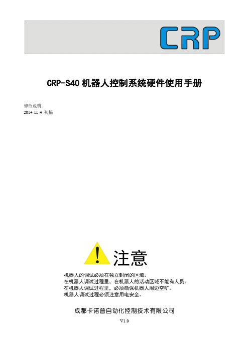
CRP-S40系统硬件说明书V1.0
CRP-S40机器人控制系统硬件使用手册修改说明:2014-11-4 初稿注意机器人的调试必须在独立封闭的区域。
在机器人调试过程里,在机器人的活动区域不能有人员。
在机器人调试过程里,必须确保机器人周边空旷。
机器人调试过程必须注意用电安全。
成都卡诺普自动化控制技术有限公司V1.0一、CRP-S40控制系统各部件外观图及安装尺寸图1、主机箱外观图主机箱安装尺寸图主机箱面板分布2、示教盒示教盒外观图示教盒信号线缆穿线示意图二、控制系统控制部分电气互联示意图三、系统安装环境系统必须牢固的安装在电柜内,四周应保留一定(不小于100mm)的空间,保证空气上下流通;系统周围应无强磁、强电干扰源,尽量远离易燃、易爆物品和各种危险品。
系统具体环境要求如下表:运行 0℃ ~ +45℃温度储存 -20℃~ +60℃湿度 10~90RH振动 ≤0.5G电源 AC220V +10% - -15% 50/60Hz 150W必需用隔离变压器供电, 变压器初级输入电压要求使用AC380V。
环境 避免粉尘、油雾及腐 、蚀性气体、通风良好四、接口定义1、电源接口本系统电流为交流AC220V输入,其必须经隔离变压器供,容量不小于200W。
注意:统必须可靠接地,否侧会造成设备故障或事故。
2、TP(示教盒)接口引脚定义作用:连接示教盒引脚名称定义有效状态接收 RS232COM41 COM4_RXD键盘数据信号脉冲信号(双向)2 K_DATA3 AD0+ 液晶LVDS信号差分信号(输出)4 AD1+ 液晶LVDS信号差分信号(输出)5 AD2- 液晶LVDS信号差分信号(输出)急停信号 0V有效(输入)6 E_STOP选择开关1 0V有效(输入)7 SWITCH18 GND 地线0V \9 +24V 输出+24V \COM4发送 RS23210 COM4_TXD11 HB 手轮B信号极电极开路(输入)键盘时钟信号脉冲信号(双向)12 K_CLOCK13 AD0- 液晶LVDS信号差分信号(输出)14 AD2+ 液晶LVDS信号差分信号(输出)15 ACLK- 液晶LVDS信号差分信号(输出)安全开关2 0V有效(输入)16 SAFE-SW2LCD灯管控制 0V有效(输出)17 LCD_CON18 +24V 输出+24V \19 HA 手轮A信号极电极开路(输入)20 SOUND 蜂鸣器控制 0V有效(输出)安全开关3 0V有效(输入)21 SAFE-SW322 AD1- 液晶LVDS信号差分信号(输出)23 ACLK+ 液晶LVDS信号差分信号(输出)安全开关1 0V有效(输入)24 SAFE-SW1选择开关2 0V有效(输入)25 SWITCH226 GND 地线0V \说明:该接口与示教相连,其线缆长度标准规格为6米,使用不同规格时需用系统厂家联系不得随意更改线缆长度,更不能在线缆中间加连接头。
S80,40控制系统调试使用说明(V1.1)

Pr0.16
Pr5.04
通讯参 数设置
(绝对伺 服电机才 需设置该
功能)
Pr5.29 Pr5.30 Pr5.31
成都卡诺普自动化控制技术有限公司
CRP Automation Control Technology Co.ltd
0
制动器动作时间 当伺服使能撤消时立即输出制动信号
300 制动器动作动速 设置电机转动时输出制动信号的转动速度
设置为方向+脉冲方式
3 输入脉冲方式 PN200
xxx0
PN200
xxx0 注:x 表示不修改其值,初始为多
就为多少
4
反馈脉冲
PN201
2500
PN212
2048
当编码器分辨率为 13Bit 时只能设 置为 2048,高于 13Bit 设置为 2500
设置电机一圈需要 6000 个脉冲,
5 电子齿轮分子 PN202
10 正反转禁止取 PN50A
11
消
PN50B
12
13
抱闸设置
14
PN50E PN50F PN512
15 外接制动电阻 PN600
8100
xxx8
3200 0100 0000
16 自动增益设置
17
刚性设置
18 转矩限制设置
PN110 FN001 PN402
PN403
xxx1 1-4 100-300
-3–
Your needs ,We have
NO:21
NO:23
扩展参 数1
NO:27 NO:41
NO:28 NO:33
成都卡诺普自动化控制技术有限公司
CRP Automation Control Technology Co.ltd
Semico OTP编程器v4[1].0使用说明v1.2
![Semico OTP编程器v4[1].0使用说明v1.2](https://img.taocdn.com/s3/m/e23770184431b90d6c85c732.png)
Semico 8-Bit OTP MCU编程器v4.0版用户使用手册V1.2版本说明:版本日期作者描述巫建刚初始版本1.0 2008/12/211.1 2009/1/14 巫建刚增加对CS98P258各种封装能否进行频率校准的说明1.2 2009/2/11 巫建刚增加离线模式下对CS77P17烧写出错信息显示的说明1 Semico OTP编程器介绍 (3)1.1简介 (3)1.2功能概述 (3)1.3硬件介绍 (3)1.4硬件电路组装 (5)1.5配件说明 (6)2 软硬件安装 (7)2.1软件安装 (7)2.2硬件电路连接 (11)2.3 USB驱动安装 (12)3 芯片联机烧录操作 (16)3.1芯片联机烧录步骤 (16)3.2滚动码操作 (25)3.2 CS98P153频率校准 (26)4 芯片脱机烧录操作 (27)4.1下载烧录代码 (27)4.2芯片脱机烧录步骤 (28)5 LCD显示说明 (29)5.1 LCD显示框图: (29)5.2 离线烧写模式下LCD显示信息 (29)5.2.1 不带频率校正和滚动码的芯片烧写时显示信息 (29)5.2.1 频率校正和滚动码显示信息 (31)6 模式选择说明 (33)7 注意事项 (34)8 部分OTP芯片转接口定义 (35)CS98P258 (35)CS8L01PY、CS8K01P (35)CS87P06(老版本) (36)CS98P806 (36)CS87P06(新版本) (37)CS98P153 (37)CS98P259 (38)CS53P84 (39)CS53P85 (39)CS77P17 (40)1Semico OTP编程器介绍1.1简介本说明介绍了Semico OTP编程器的硬件及软件使用。
Semico OTP编程器功能强大,是一款支持多种Semico 8-Bit OTP MCU的新一代烧录器,具有在线和离线烧录功能,采用USB接口通讯,可通过USB口与PC通讯直接进行在线烧录,也可以将待烧录代码下载到SPI FLASH,从而支持离线烧录。
TV160编程器 SPI FLASH编程器使用操作说明书
片)芯片和待写芯片(子片)都放好时,编程器自动检测出器件容量和读写算法,并将数
据源芯片中的数据拷贝到待写芯片。当连接到电脑读写时,请不要放数据源(母片)芯片。
5. 固件升级:用户可以从彩电维修资料网的支持网站获取最新的固件升级到编程器中。
6. 支持芯片全面:全面支持 25 系列 SPI FLASH、24 EEPROM、25 EEPROM、93 EEPROM。
3.8
AT93C86
16Kbit
1.3
写时间(秒) 1.0 3.4 1.0 10.1 11.7 6.5 9.3 29.3 0.7 6.0 3.0
校验时间(秒) 0.4 0.4 0.4 3.1 3.1 3.1 3.1 13.2 0.3 3.8 1.3
4. 免按键全自动脱机拷贝:本编程器有自动检测芯片是否放好的功能,当检测到数据源(母
母片:脱机拷贝时的数据源(内有数据)芯片。 子片:脱机拷贝时的待烧写(空芯片)芯片。 在放置芯片时注意芯片方向,请按编程器标识的方向放入。
2.1 脱机拷贝如下图连接:
芯片放 置位置
将电源通电 后,稍等,黄 灯变红灯后, 即完成复制
电源自配,只要 是 5V 的输出, 并是标准的 USB 接口即可使用, 建议选择质量好 的稳压电源
M25PX64
MXIC
MX25L512 、 MX25L1005 、 MX25L2005 、 MX25L4005 、 MX25L8005 、 MX25L1605 、 MX25L3205、MX25L6405
PMC
PM25LV512A、PM25LV010A、PM25LV020、PM25LV040、PM25LV080B、PM25LV016B
7. USB 接口供电:系统运行时总功耗不超过 100mA,一般电脑 USB 口供能能力都在 500mA 左
P800Flash 量产型 Flash 编程器产品用户手册说明书

广州致远电子有限公司P800Flash量产型Flash 编程器修订历史目录1. P800Flash编程器简介 (1)2. eMMC烧录方案信息表 (2)3. eMMC烧录功能介绍 (3)3.1创建 (3)3.1.1新建工程 (3)3.1.2芯片选择 (4)3.1.3烧录方式 (4)3.2配置 (5)3.2.1芯片选择 (6)3.2.2通道配置 (6)3.2.3组合配置 (7)3.2.4芯片配置 (7)3.2.5操作选项 (8)3.3保存 (9)3.4操作 (9)4. eMMC烧录操作流程 (11)4.1方式一、文件调入 (11)4.1.1创建工程 (11)4.1.2选择芯片 (12)4.1.3烧录模式 (12)4.1.4时钟频率 (13)4.1.5调入文件 (13)4.1.6ExtCSD寄存器配置 (15)4.1.7通道配置 (16)4.1.8保存工程 (17)4.2方式二、文件分析 (18)4.2.1创建工程 (18)4.2.2选择芯片 (19)4.2.3烧录模式 (19)4.2.4时钟频率 (20)4.2.5分析文件 (20)4.2.6ExtCSD寄存器配置 (23)4.2.7通道配置 (24)4.2.8保存工程 (25)4.3方式三、母片分析 (26)4.3.1创建工程 (26)4.3.2选择芯片 (27)4.3.3烧录模式 (27)4.3.4时钟频率 (28)4.3.5分析母片 (29)4.3.6通道配置 (31)4.3.7保存工程 (32)4.4方式四、母片拷贝 (32)4.4.1创建工程 (33)4.4.2选择芯片 (34)4.4.3烧录模式 (34)4.4.4时钟频率 (35)4.4.5分析母片 (35)4.4.6通道配置 (38)4.4.7保存工程 (38)5. eMMC芯片烧录 (40)5.1量产烧录 (40)5.2芯片测试 (40)5.3日志文件 (41)5.3.1即时信息 (41)5.3.2Log文件 (41)6.免责声明 (43)1. P800Flash编程器简介P800Flash是广州致远电子有限公司历经十多年的编程技术积累,深耕打造的一款脱机、座烧、量产型的Flash编程器;它能支持各种封装的EEPROM Flash、SPI NorFlash、Parallel NorFlash、NandFlash、SPI NandFlash、eMMC等存储器。
SP40用户编程手册
SP40 用户编程手册V1SP40 编程环境软件需求: 1. keil (C51)本人使用的是4.54 版本2. SP40编译工具Infineon SP3x Keil Driver Setup.exe使用烧录器版安装 Keil 之后,需要安装 SP370 编译工具,才能编译出 SP40 的执行文件需要自行添加1.如何创建第一个例程(01.测试LED )1.1 创建需要的文件夹如右图文件结构1.2 项目创建SP40为 8051 内核核,所以可以选择一个 8051的项目来创建 。
SP370硬 件 与8052 一致,这里选择8052,其实 51内核 的编译器都是一致的, 选 不同的 IC 没有影响。
1.3 目录机构1.4 配置(SP40 的 CODE 地址为 0xC000,大小为 0x2FFF, RAM 地址 0xFF60,0x00A0)1.5 编译与结果在Object 文件下生成LED.hex,(通过烧录器烧录,可以看到PP2,PP3 对应的LED 灯被点亮)。
1.6 程序说明整个程序是一个寄存器配置的过程(详见SP40_UserManual.pdf Page:38)程序运行过程中需要不断”喂看门狗”,否则系统会重启。
2.使用SP40 内部库函数(02.闪烁LED)此例程使用到库函数(Aux_Delay_10us)2.1 Aux 库函数Aux 提供了一些较为常用的库函数,例如延时函数,串口使用等函数。
Aux 相关的库函数使用可以查阅 SP40_Aux_Lib.h 文件2.2目录机构2.3 编译与结果在Object 文件下生成LED_FLASH.hex可以看到PP3 对应的LED 灯开始闪烁,闪烁频率为1s 2.4 程序说明通过内部库函数Aux_Delay_10us 提供精确的延时。
同时使用内部库函数,可以节省大量的程序空间。
3.实现Printf 函数(03.测试UART)说明:在调试过程中,Printf 函数是最好用一种方式,可打印任何用户想要看到的数据。
归钜泉光电科技(上海) ATT7025 7027 单口编程器 说明书(210-SD-128)

ATT7025/7027单口编程器使用手册Tel: 021-********Fax: 021-********Email: sales@ Web: 目录1概述 (4)2适用范围 (4)3单口编程器配件 (4)4单口编程器功能 (4)5单口编程器硬件示意图 (4)6单口编程器原理框图 (5)7联机模式操作规程 (5)7.1硬件连接 (5)7.2PC端软件外观 (5)7.3操作流程(具体请看后面的图示说明) (6)7.4详细操作图示说明 (6)8脱机模式操作规程 (11)9编程中会出现的错误 (11)9.1第一类错误情况 (11)9.2第二类错误情况 (11)1概述单口编程器是针对ATT7025 / 7027在量产的时候编程使用的工具,电脑通过串口将用户需要下载的程序以及校验和传送到编程器内主控芯片的外部Flash中,当用户将需要烧写的目标芯片放入socket内的时候,通过点击编程器面板的红色按钮或者使用软件中的相应按钮,主控芯片会将其外部Flash中的数据烧写到目标芯片中,并计算校验和与之前存在主控芯片外部flash的数据比较,从而保证程序烧写的正确性。
2适用范围ATT7025 / 7027 系列芯片3单口编程器配件ATT7025/7027单口编程器硬件公-母串口连接线单口串行编程器软件单口串行编程器软件使用说明(在公司网站下载)AC-DC电源适配器:9V---12V4单口编程器功能支持使用PC对目标芯片编程支持脱机编程编程完成后自动校验5单口编程器硬件示意图6单口编程器原理框图7联机模式操作规程7.1 硬件连接将编程器与PC用串口线相互连接,接入AC-DC电源适配器,打开编程器电源,此时电源指示灯应该点亮,说明电源供电正常。
7.2 PC端软件外观(1) OpenPort ――― 打开串口(2) OpenFile ——― 打开一个Hex文件,以Bin文件的形式在左边窗口中显示(3) FlashErase ――― 擦除主控芯片的Flash(4) FlashWritten ――― 将要烧写的的程序内容写入主控芯片外挂的Flash内,同时会计算写入程序的校验码,并将其显示在Checksum1窗口,校验码是32K地址空间所有数据的累加和。
Silicon Laboratories Si4010 RF SoC 开发板快速启动指南说明书
Rev 0.1 6/12Copyright © 2012 by Silicon Laboratories AN690EVELOPMENT IT UICK TART UIDE 1. PurposeThank you for your interest in Silicon Laboratories Si4010 RF SoC transmitter development kit. This developmentkit contains everything you need to develop your software with the Si4010 embedded Si8051 MCU. The kit hasthree versions: one for the 434MHz band (P/N 4010-KFOBDEV-434), one for the 868MHz band (P/N 4010-KFOBDEV-868) and one for the 915MHz band (P/N 4010-KFOBDEV-915). The key features of the developmentplatform are as follows:⏹ The key fob development board has five push buttons and one LED.⏹ The key fob development board has a battery to enable disconnect from the programming interface boardand SMA antenna output to allow wired measurements.⏹ Uses Silicon Laboratories Integrated Development Environment (IDE) for software debugging and can alsouse Keil C compiler, assembler, and linker.⏹ Interfaces with Silicon Laboratories USB Debug Adapter or Toolstick.⏹ Contains a socketed key fob development board for burning the OTP NVM memory. Contains Si4355receiver board for link testing.⏹ Contains three blank NVM Si4010 chips and key fob demo boards without IC for burning and testing usercode on an actual key fob PCB.2. Kit ContentTable 1 lists the items contained in the kits.Table 1. Kit Content QtyPart Number Description 4010-KFOBDEV-434Si4010 Key Fob Development Kit 434MHz 24010-KFOB-434-NF Si4010 key fob demo board 434MHz w/o IC 1MSC-DKPE1SOIC/MSOP socketed development board 3Si4010-C2-GS Si4010-C2-GS transmitter IC, SOIC Package 14010-DKPB434-BM Si4010 MSOP key fob development board 434 MHz, SMA 14355-LED-434-SRX Si4355 RFStick 434MHz receiver board 1MSC-PLPB_1Key Fob Plastic Case (translucent grey)1MSC-BA5Programming interface board 1MSC-BA4Burning adapter board 1EC3USB Debug Adapter 1Toolstick_BA Toolstick Base Adapter 1MSC-DKCS5USB Cable 1USB extender cable (USBA-USBA)2AAA AAA battery 2CRD2032CR2032 3V coin batteryAN690Table 1. Kit Content (Continued)4010- KFOBDEV-868Si4010 Key Fob Development Kit 868MHz 24010-KFOB-868-NF Si4010 key fob demo board 868MHz w/o IC1MSC-DKPE1SOIC/MSOP socketed development board3Si4010-C2-GS Si4010-C2-GS transmitter IC, SOIC Package14010-DKPB868-BM Si4010 MSOP key fob development board 868 MHz, SMA14355-LED-868-SRX Si4355 RFStick 868MHz receiver board1MSC-PLPB_1Key Fob Plastic Case (translucent grey)1MSC-BA5Programming interface board1MSC-BA4Burning adapter board1EC3USB Debug Adapter1Toolstick_BA Toolstick Base Adapter1MSC-DKCS5USB Cable1USB extender cable (USBA-USBA)2AAA AAA battery2CRD2032CR2032 3V coin battery4010- KFOBDEV-915Si4010 Key Fob Development Kit 915MHz 24010-KFOB-915-NF Si4010 key fob demo board 915MHz w/o IC1MSC-DKPE1SOIC/MSOP socketed development board3Si4010-C2-GS Si4010-C2-GS transmitter IC, SOIC Package14010-DKPB915-BM Si4010 MSOP key fob development board 915MHz, SMA14355-LED-915-SRX Si4355 RFStick 915MHz receiver board1MSC-PLPB_1Key Fob Plastic Case (translucent grey)1MSC-BA5Programming interface board1MSC-BA4Burning adapter board1EC3USB Debug Adapter1Toolstick_BA Toolstick Base Adapter1MSC-DKCS5USB Cable1USB extender cable (USBA-USBA)2AAA AAA battery2CRD2032CR2032 3V coin batteryAN690Figure1.Burning Adapter Board (P/N MSC-BA4)Figure 2.Si4010 Socketed Key Fob Development Board (P/N MSC-DKPE1)Figure3.Si4010 MSOP Key Fob Development Board 434MHz, SMA (P/N 4010-DKPB434-BM)Note:Instead of this board, the 434MHz development kits may contain the pcb antenna version of this board called the Si4010 key fob development board 434MHz (P/N 4010-DKPB_434).Figure4.Si4355 RFStick 434MHz Receiver Board (P/N 4355-LED-434-SRX)AN690Figure 5.4010 Key Fob Demo Board 434MHz w/o IC (P/N 4010-KFOB-434-NF)Figure6.Key Fob Plastic Case (Translucent Grey) (P/N MSC-PLPB_1)Figure 7.EC3 Debug Adapter (P/N EC3)Figure 8.Toolstick Base Adapter (P/N Toolstick_BA)AN690 3. Software InstallationThe software and documentation pack for the development kit is available as a zip file on the Silicon Labs website at /products/wireless/EZRadio/Pages/Si4010.aspx on the Tools tab. The provided software pack contains all the documentation and files needed to develop a user application. It also contains example applications using API functions and the key fob demo application.The directory structure of the software examples is as follows:+--Si4010_projects| +--aes_demo| | +--bin .. Keil uVision and SiLabs IDE files| | +--out .. output directory for Keil toolchain| | +--src .. aes_demo source code| +--common| | +--lib .. Si4010 additional API functions library| | +--src .. Si4010 required files| +--fcast_demo.. frequency casting (tuning) demo| | +--bin| | +--out| | +--src| +--fstep_demo.. frequency two step tuning demo| | +--bin| | +--out| | +--src| +--tone_demo.. continuous wave (tone) demo| | +--bin| | +--out| | +--src| +--keyfob_demo.. simple keyfob demo| | +--bin| | +--out| | +--src| +--rke_demo.. advanced keyfob demo with AES| | +--bin| | +--out| | +--srcCopy the directory structure in a directory of your choice. It is recommended to keep the structure of the Si4010_projects folder to allow the compiler to find the Si4010 common files. Each project has a *.wsp project file in the bin folder that contains all the settings of the IDE for the project, including the relative path of the common files.AN6904. Silicon Labs IDE RunDownload the Silicon Labs IDE (Integrated Development Environment) from the following URL:/products/mcu/Pages/SiliconLaboratoriesIDE.aspx and install it on your computer. To run theSilicon Labs IDE, open an *.wsp project file.5. Hardware Setup using a USB Debug AdapterA detailed description about the IDE and debug adapters can be found in the Si4010 Development Kit User'sGuide.The target board is connected to a PC running the Silicon Laboratories IDE via the USB Debug Adapter as shownin Figure 9.Figure 9.Target Board and Debug AdapterPerform the following steps to set up the debug adapter:1. Connect the EC3 Debug Adapter to the J2 connector on the Burning Adapter board with the 10-pin ribboncable.2. Connect one end of the USB cable to the USB connector on the USB Debug Adapter.3. Connect the other end of the USB cable to a USB Port on the PC.4. Reset the firmware of the Debug adapter by running the following application:\Silabs_IDE\usb_debug_adapter_firmware_reset.exe(This operation needs to be done only once per USB Debug Adapter before a new version of the IDE canbe used.)5. Run Silabs_IDE\ide.exeThe first time the IDE program is run, it will automatically update the correct firmware for the adapter.Note:Remove power from the target board and the USB Debug Adapter before connecting or disconnecting the ribbon cablefrom the target board. Connecting or disconnecting the cable when the devices have power can damage the deviceand/or the USB Debug Adapter.AN690 6. Keil Toolchain IntegrationThe project files in examples assume that the Keil toolchain is installed to: C:\Keil directory. The location of the Keil toolchain can be easily changed in the Silabs IDE in the Project—Tool Chain Integration menu. An evaluation version of the Keil toolchain can be downloaded from the Keil web site, /. This free version has 2kB code limitation and starts the code at 0x0800 address. The Keil free evaluation version can be unlocked to become a 4k version with no code placement limitation by following the directions given in application note “AN104: Integrating Keil 8051 Tools into the Silicon Labs IDE”, which covers Keil toolchain integration and license management. The unlock code can be found in the documentation pack mentioned in "3. Software Installation" on page 5 of this document. You can find the unlock code in the root folder in the Keil_license_number.txt file. Contact your Silicon Laboratories sales representative or distributor for application assistance.7. Known IssuesThere is an issue related to the LED driver, which demonstrates itself only under the following circumstances when all three conditions are satisfied:1. The device programming level is Factory or User. For those levels, the C2 debugging interface is enabledafter the boot by a boot routine.2. The device has been disconnected from the Silicon Labs IDE. “Disconnected” is meant in the softwaresense (not physically) using the Connect/Disconnect buttons on IDE, or the device is running the Usercode automatically after the boot without ever being connected to the IDE.3. The device is running a code that turns the LED on and off.If all the conditions are satisfied, after the first LED blink when the LED is turned off, the GPIO4 stops working and is no longer visible to the application.If the device programming level is Run or the C2 debugging interface is internally disabled, there is no issue. The LED can be turned on and off without affecting the device GPIO4 functionality.The issue can be summarized as follows: Whenever the C2 debugging interface is enabled and the device is not connected to the IDE and the LED is turned on and off, then the GPIO4 will stop functioning. Since, in Run mode, the C2 is disabled after the boot process finishes, the GPIO4 is not affected.Therefore, this issue only affects the software development process and inconveniences the developer. After the application is finalized and the chip is programmed as Run, there is no issue.There are several possible software workarounds; see details in the Si4010 key fob development kit user guide.Disclaimer Silicon Laboratories intends to provide customers with the latest, accurate, and in-depth documentation of all peripherals and modules available for system and software implementers using or intending to use the Silicon Laboratories products. Characterization data, available modules and peripherals, memory sizes and memory addresses refer to each specific device, and "Typical" parameters provided can and do vary in different applications. Application examples described herein are for illustrative purposes only. Silicon Laboratories reserves the right to make changes without further notice and limitation to product information, specifications, and descriptions herein, and does not give warranties as to the accuracy or completeness of the included information. Silicon Laboratories shall have no liability for the consequences of use of the information supplied herein. This document does not imply or express copyright licenses granted hereunder to design or fabricate any integrated circuits. The products must not be used within any Life Support System without the specific written consent of Silicon Laboratories. A "Life Support System" is any product or system intended to support or sustain life and/or health, which, if it fails, can be reasonably expected to result in significant personal injury or death. Silicon Laboratories products are generally not intended for military applications. Silicon Laboratories products shall under no circumstances be used in weapons of mass destruction including (but not limited to) nuclear, biological or chemical weapons, or missiles capable of delivering such weapons.Trademark Information Silicon Laboratories Inc., Silicon Laboratories, Silicon Labs, SiLabs and the Silicon Labs logo, CMEMS®, EFM, EFM32, EFR, Energy Micro, Energy Micro logo and combinations thereof, "the world’s most energy friendly microcontrollers", Ember®, EZLink®, EZMac®, EZRadio®, EZRadioPRO®, DSPLL®, ISOmodem ®, Precision32®, ProSLIC®, SiPHY®, USBXpress® and others are trademarks or registered trademarks of Silicon Laboratories Inc. ARM, CORTEX, Cortex-M3 and THUMB are trademarks or registered trademarks of ARM Holdings. Keil is a registered trademark of ARM Limited. All other products or brand names mentioned herein are trademarks of their respective holders. Silicon Laboratories Inc.400 West Cesar Chavez Austin, TX 78701USASimp li city StudioOne-click access to MCU tools,documentation, software, sourcecode libraries & more. Availablefor Windows, Mac and Linux!/simplicityMCU Portfolio /mcu SW/HW /simplicity Quality /quality Support and Community。
PSOCISSP编程器使用说明
PSOCISSP编程器使用说明Cypress PSOC ISSP 编程器烧录器PSoC ISSP下载器 miniprog CY3217简介:1.使用USB接口,可向目标板供电2.支持RESET和POWER-ON方式编程3.支持:CY8C21x23、CY8C21x34、CY8C21x23A、CY8C24x33、CY8C24x94、CY8C27x43、CY8C29x66,在不改变软硬件的条件下支持芯片数量可不断增加4.编程接口定义为官方标准版,如下:1.VDD 3.GND 5.XRES 7.SCLK 9.SDATA2.VDD 4.GND 6.XRES 8.SCLK 10.SDATA5.将下载器插入USB口,驱动成功安装后READY闪烁,与上位机编程软件通信正常后COM闪烁6.提供编程软件,配套光盘装箱清单:1.主机一个2.赠送5P编程电缆一个3.使用光盘(下载软件、开发软件及相关开发资料)一张B连接线一根5.五芯下载线一根填加新器件:如果增加新的芯片,PC上的上位机软件和PSoC-ISSP中的固件程序都不用改动,只要将PC上安装PSoC-ISSP编程软件目录下的“PSoC_Device.xml”文件(文本文件)中增加一行就行了。
例如,增加CY7C64215就只用了2分钟时间:在文件种添上以下几行描述:<="" banknum="2" blockperbank="128" checksumvectortype="3" id="30" name="CY7C64215-28LFXI" p="" powercyclemode="0" programvectortype="1" securitydataperbank="32" uniqueinitvector="0" uniqueprogramvector="0">ResetMode="1">。
重庆曲圣电子 PLC-40音乐喷泉控制器 使用说明
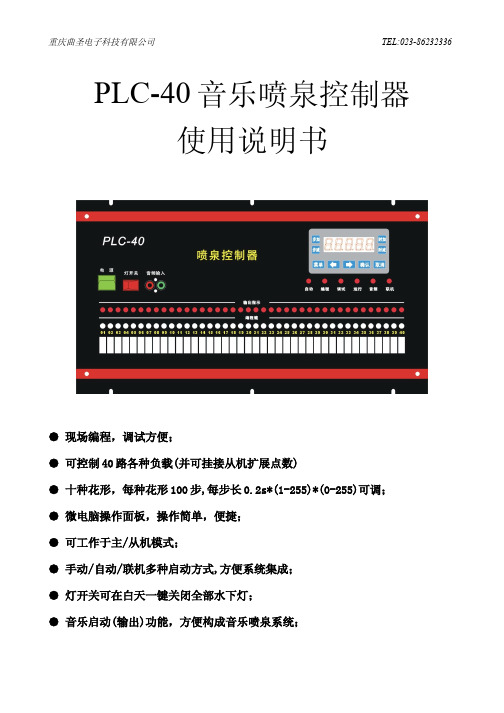
PLC-40音乐喷泉控制器使用说明书● 现场编程,调试方便;● 可控制40路各种负载(并可挂接从机扩展点数)● 十种花形,每种花形100步,每步长0.2s*(1-255)*(0-255)可调;● 微电脑操作面板,操作简单,便捷;● 可工作于主/从机模式;● 手动/自动/联机多种启动方式,方便系统集成;● 灯开关可在白天一键关闭全部水下灯;● 音乐启动(输出)功能,方便构成音乐喷泉系统;● 内置时钟模块、485通讯端口;● 4组定时启/停程序指令;● 输入/输出光电隔离,安全可靠;一、概述PLC-40程序控制器是一种专用于音乐喷泉、程控喷泉的可编程控制器,控制器面板简洁、美观、实用;内核采用当代最先进的MCU技术,功能强大、性能稳定可靠、超强抗干扰;使用方便,内置音乐信号检测模块、时间日历模块、2路可编程外部端子输入、RS-485总线、40路光电隔离输出、水下灯开关,10种花型、每种花型100步可编程,可单独用于程控或音乐喷泉,也可与工控机或PC机联机实现电脑音乐喷泉;是中小型程控、音乐喷泉的最佳选择。
1、控制面板简洁、美观、实用,输入及输出全部数字化,并用数码管显示,准确、直观,可存储多达 10种花形,每种花形100 步程序,每步程序之间的间隔时间独立可调0.2s*(1-255)*(0-255)可调,用户编程非常灵活、自由。
2、操作简单,方便使用:可根据实际情况现场编程,输入信息自动存储,而且改变程序的操作只须通过简单的按键操作即可完成。
3、系统功能菜单分为两组,只有输入正确的密码,才能调出第二组菜单,实现编程等高级功能,避免程序被随意修改。
4、控制器设有调试工作模式,调试模式下可通过面板上的编程键控制任何一路负载的启动或停止,方便调试线路、设备及水型、。
5、面板上设有水下灯开关,白天时可一钮化关掉所有水下灯,夜晚时又可一钮化将水下灯打开,由程序控制水下灯。
6、音乐启动(输出)功能,可由音乐信号控制程序是否输出,方便构成音乐喷泉,也可直接输出,做成程控喷泉。
编程器使用说明
编程器使用说明PSD编程器使用说明一. 安装PSDSoft Express软件将文件解压后直接运行SETUP.EXE进行安装,运行于WINDOW98与WINDOWME下面,在NT与WINDOW2000下可能会出现运行不稳定的情况。
在安完成以后直接运行程序即可。
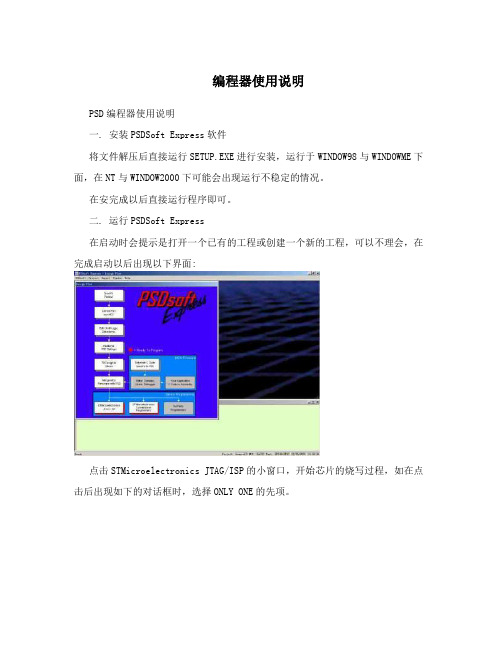
二. 运行PSDSoft Express在启动时会提示是打开一个已有的工程或创建一个新的工程,可以不理会,在完成启动以后出现以下界面:点击STMicroelectronics JTAG/ISP的小窗口,开始芯片的烧写过程,如在点击后出现如下的对话框时,选择ONLY ONE的先项。
在完成启动后将出现如下的对话框:在第一步当中选择要进行编程的OBJ文件(对话框图Select folder and programming file),此文件将由创网公司提供。
在器件类型(Select device:)当中选择PSD813F1V的型号。
在第二步当中的所有选择项目设为和上图一样的选项,然后按Execute按钮开始对PSD813F1V进行编程,在编程过程当中有相应的信息出现。
三. 出错处理出错信息一:表示并口线没有正确接到PSD的烧写器,请检查电缆是否连接好。
出错信息二:出现以上错误时,表示PSD烧写器没有加电,请检查电源线是否接好。
出错信三:出现以上错误时,表示芯片可能在插座上插反了,如芯片没有插错,且经多次重次以后仍是这种状态,表示这个PDS已经被锁定,不能由PDS FLASH进行编程。
在完成编程以后将信息窗的显示如下:四. 接线说明USB PC并行口开关电源PSD芯片插座外接编程口1. 并行口使用25芯的电缆接到PC机,必须连接正确才可以使用。
2. USB口主要是用于从PC机当中引出电源,可以不接,此时必须通过电源插座接入直流电源,电压为3.5-5.5V。
3. 电源接口在没有接入USB电源时使用。
4. PSD芯片插座可以插入PSD芯片,要求芯片的缺口应与上图所示的相一致。
编程器教程
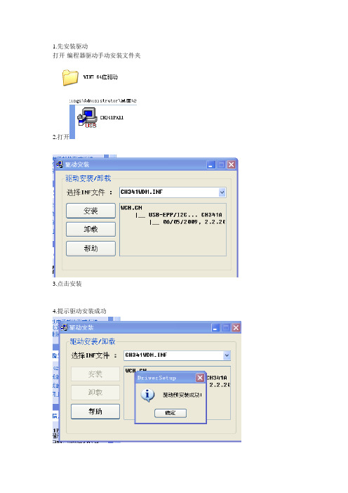
1.先安装驱动
打开-编程器驱动手动安装文件夹
2.打开
3.点击安装
4.提示驱动安装成功
5.打开软件文件夹
6.打开341程序插上编程器
7.软件右下角显示已连接说明驱动安装成功
8.下面安装图片我们测试25X40直插芯片(图片安装方法想见
9.按软件检测按钮检测不到或者型号不一致就手动选择你的型号
显示检测到芯片25X40
10.芯片检测OK 以后要读取芯片的话按读取
11.稍等片刻软件下角提示
12.点击保存按钮保存好读取的文件到你的制定的位置
13.编程方法
14.检测到芯片型号以后按载入你的文件
15.如果没有显示你的文件请文件类型选择所有文件
16.载入文件以后直接按自动按钮
17稍等片刻软件提示
就是编程完成!。
- 1、下载文档前请自行甄别文档内容的完整性,平台不提供额外的编辑、内容补充、找答案等附加服务。
- 2、"仅部分预览"的文档,不可在线预览部分如存在完整性等问题,可反馈申请退款(可完整预览的文档不适用该条件!)。
- 3、如文档侵犯您的权益,请联系客服反馈,我们会尽快为您处理(人工客服工作时间:9:00-18:30)。
SP40编程器使用手册技术支持:517372477(QQ)
目录
1. SP40编程器 ...........................................................................................................1-3
1.1编程软件................................................................................................................... 1-4
1.2功能介绍................................................................................................................... 1-5
1.3操作介绍................................................................................................................... 1-7
1. SP40编程器
此编程器专门为英飞凌SP40(TPMS,胎压监测)配套使用。
图 1.1 SP40芯片
图 1.2 SP40编程器
SP40操作界面如下:
●电源指示灯
●运行指示灯
●脱机烧写按键
●ISP接口:VCC PP0 PP1 PP2 GND(2X5)
图 1.3 SP40编程器界面
1.1 编程软件
SP40编程器软件图标是一个IC,如下图。
图 1.4 编程软件图标编程软件界面如下图。
图 1.5 编程软件界面
1.2 功能介绍
界面功能介绍如下:
1. 串口部分
【Open】:打开串口
【Refresh】:刷新串口列表
【编程器版本】:17020100
图 1.6 串口部分
2. Hex文件部分
【Download】:将Hex文件下载到编程器,用于脱机烧写
【Upload】Hex文件,方便查询存在于编程器的Hex文件【…】:浏览文件,选择Hex文件路径
【0】:HEX有多少行,已经是Hex-32格式(Keil生成的是Hex-80格式)
图 1.7 Hex文件部分
3. 操作部分
【Program】:在线编程按钮,单击直接将Hex文件下载到SP40(一键完成模式切换、擦除、编程和校验),最后直接恢复到NORMAL模式(SP40程序正常运行)【Erase】:在线擦除按钮,单击擦除SP40,必须先进入PROGRAMMING模式
【Verify】:CRC16校验,校验下载的程序的CRC16,必须先进入PROGRAMMING模式
【Normal】:模式切换,PROGRAMMING和NORMAL直接切换
【Set/Get Tire ID】:设置SP40编码(人为设定,选用),起始地址0x5780(User Code Config Sector),字节数(最多128字节)以及数据内容(16进制)
图 1.8 操作部分
4. Sensor部分
【Start】:启动读取SP40的气压、加速度、温度和电压参数,读取必须先进入PROGRAMMING模式
图 1.9 Sensor部分
5. 打印信息部分
打印操作过程中的相关信息,包括Hex文件内容和操作成功/失败等信息。
【Read】:在地址框输入起始地址,以及需要读取多少行数据(每行32字节);例如0x4000,10,即读取从0x4000开始,连续10行的数据
【Save】:保持打印信息
【Clear】:清除打印信息
图 1.10 打印信息部分
1.3 操作介绍
1. 连接硬件
通过仿真电缆连接编程器和目标板(SP40),如下图。
将编程器通过USB连接PC,通电时编程器蜂鸣器响1声。
2. 打开软件
打开软件,同时选择对应串口(如果只连接了一个仿真,只会显示一个串口),单击【Open】。
图 1.11 打开串口3. 打开Hex文件
在Hex文件部分,选择【…】选择Hex文件路径。
图 1.12 打开hex文件1 选择需要下载的hex文件。
图 1.13 打开hex文件2
图 1.14 打开hex文件3 4. 在线编程
单击【Program】按钮,直接将程序下载到SP40。
图 1.15 在线编程
5. 读取Flash
单击【Normal】按钮,先进入PROGRAMMING模式,否则会出现错误提示。
图 1.16 模式错误
图 1.17 读取Flash数据
与之前编程时的打印信息对比,比较写入和读出的数据。
图 1.18 编程时写入的数据
图 1.19 连续读多行
6. 保存打印信息
单击【Save】按钮,保存打印信息,包括之前编程时的Hex文件。
在SP40编程软件所在的文件夹,可以找到三个文件:
Program-HexFile.txt:编程时打印的Hex信息,未执行在线编程时为空
Upload-HexFile.txt:读取编程器的Hex文件,未执行upload操作时为空
Log.txt:日志信息,保存最后打印的信息。
图 1.20 保存打印信息
图 1.21 打印信息文件
图 1.22 打印信息文件内容
7. 读取传感器
读取传感器,要先进入PROGRAMMING模式,否则同样出现错误提示。
图 1.23 读取传感器
改变目标板(SP40)的方向,加速度值发生变化。
如果用手按着SP40,使其温度升高,同样可以看到温度变化。
图 1.24 读取传感器-温度
8. 设置Tire ID
在SP40例程代码,将0x57E0后续4个字节作为Tire ID(地址必须是32的倍数,例如0x5781就会导致数据无法写入),因而可以通过编程软件修改Tire ID。
图 1.25 设置Tire ID-修改地址
图 1.26 设置Tire ID-设置ID
图 1.27 设置Tire ID-清空数值框
图 1.28 设置Tire ID-读取ID
图 1.29 设置Tire ID-读取0xF304地址
9. 脱机编程
脱机编程时方便生产时使用,如果新的编程,单击【Upload】按钮会提示不存在Hex 文件。
在Hex文件部分,选择【…】选择Hex文件路径。
图 1.30 打开hex文件1
选择需要下载的hex文件。
图 1.31 打开hex文件2
图 1.32 打开hex文件3 单击【Download】按钮,将Hex文件下载到编程器。
图 1.33 Download hex文件单击【Upload】按钮,读取编程器内的Hex文件。
图 1.34 Upload hex文件
关闭编程器软件,重新给编程器上电。
按编程器上的【Prog】按钮,蜂鸣器响2声表明脱机编程成功。
10. 脱机运行
重新给SP40断电,PP3连接到USB转串口的RXD(TTL电平),打开串口调试工具,程序脱机运行。
程序会自动从睡眠启动,然后复位运行。
图 1.35 脱机运行。
