魔灯中文说明书
魔尼闪LED闪光灯说明书
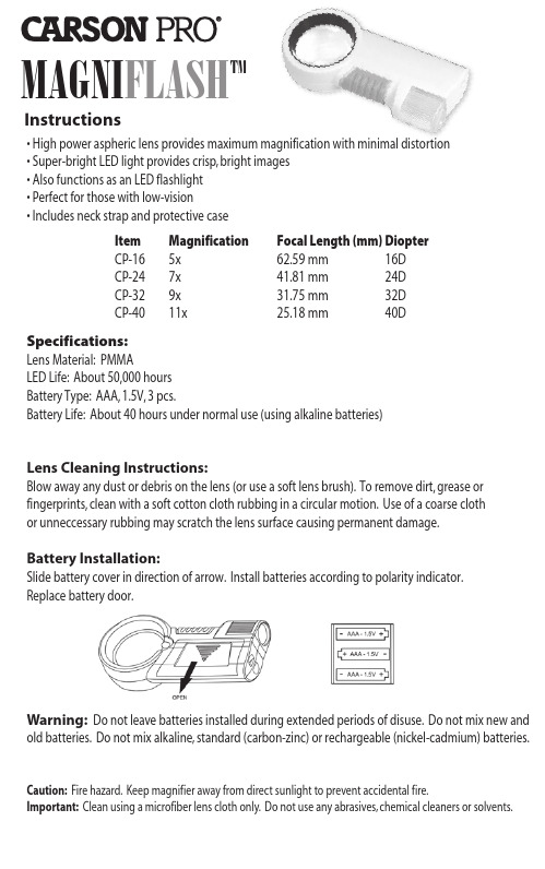
MAGNI FLASH TM Instructions • High power aspheric lens provides maximum magnification with minimal distortion • Super-bright LED light provides crisp, bright images • Also functions as an LED flashlight • Perfect for those with low-vision • Includes neck strap and protective case Item Magnification Focal Length (mm) DiopterCP-16 5x 62.59 mm 16D CP-24 7x 41.81 mm 24D CP-32 9x 31.75 mm 32D CP-40 11x25.18 mm 40D Specifications: Lens Material: PMMA LED Life: About 50,000 hours Battery Type: AAA, 1.5V, 3 pcs.Battery Life: About 40 hours under normal use (using alkaline batteries) Lens Cleaning Instructions:Blow away any dust or debris on the lens (or use a soft lens brush). To remove dirt, grease or fingerprints, clean with a soft cotton cloth rubbing in a circular motion. Use of a coarse cloth or unneccessary rubbing may scratch the lens surface causing permanent damage.Battery Installation:Slide battery cover in direction of arrow. Install batteries according to polarity indicator.Replace battery door.Warning: Do not leave batteries installed during extended periods of disuse. Do not mix new and old batteries. Do not mix alkaline, standard (carbon-zinc) or rechargeable (nickel-cadmium) batteries. Caution: Fire hazard. Keep magnifier away from direct sunlight to prevent accidental fire.Important: Clean using a microfiber lens cloth only. Do not use any abrasives, chemical cleaners or solvents.。
AvengerII SOLO、DUO、TRIO 双类型警示灯(带线)说明书
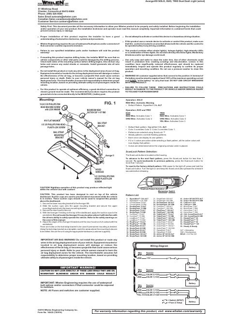
Avenger®II SOLO, DUO, TRIO Dual Dash Light (wired)CAUTION! Nighttime operation of this product may produce reflected light within the vehicle! Use with caution!CAUTION:This product has been designed to rest on top of the vehicle dashboard.Suction cups are used to prevent lateral movement while the vehicle is in motion.These suction cups should not be used to suspend this product above the dashboard.1.Secure the lower mounting bracket to theAvenger II®.2.Slide the suction cups onto the upper mounting bracket and secure the upper mounting bracket onto the lower mounting bracket.3.Secure the visor hood to the unit.4.With the Avenger II resting on the top of the dashboard,apply the suction cups to the windshield.Do not locate the Avenger II in any location where it will interfere with the drivers ability to safely operate the vehicle.Refer to the safety warnings on the cover of this manual.5.Adjust the angle of the Avenger II bracket until the visor hood is in full contact with the windshield.There are holes on the bail strap bracket to be used if permanent mounting is ing the bail strap bracket as a template,mark the areas where the mounting holes are to be drilled.Secure the unit using the appropriate hardware (customer supplied).For warranty information regarding this product, visit /warranty©2016 Whelen Engineering Company Inc.Form No. 14A22 (120916)Mounting:1.SignalAlert™CAL ALT2.SignalAlert™CAL SIMetFlash® 75ALTetFlash® 75 SIM5.DoubleFlash 75ALT6.DoubleFlash 75 SIM7.SingleFlash 75ALT8.SingleFlash 75 SIMAlert™75ALT Alert™75 SIM 11.LongBurst™75ALT 12.LongBurst™75 SIM 13.PingPong™75ALT 14.PingPong™75 SIM 15.SingleFlash 60ALT 16.SingleFlash 60 SIM 17.SingleFlash 90ALT 18.SingleFlash 90 SIM 19.SingleFlash 120ALT 20.SingleFlash 120 SIM21.SingleFlash 300ALT 22.SingleFlash 300 SIM 23.DoubleFlash 120ALT 24.DoubleFlash 120 SIM Alert™150ALT Alert™150 SIM 27.PingPong™120ALT 28.PingPong™120 SIM 29.TripleFlash™75ALT 30.TripleFlash™75 SIM 31.TripleFlash™120ALT 32.TripleFlash™120 SIM 33.ActionFlash™50ALT 34.ActionFlash™50 SIM 35.ActionFlash™150ALT 36.ActionFlash™150 SIM 37.SignalAlert 75ALT 38.SignalAlert 75 SIM 39.Action SF 60/120ALT 40.Action SF 60/120 SIM41.Action SF120/TF75ALT 42.Action SF120/TF75 SIM 43.CalScan™ALT 44.CalScan™SIM 45.ModuFlash™ALT 46.ModuFlash™SIM 47.ActionScan™ALT 48.ActionScan™SIM49.CAL CometFlash®ALT 50.CAL CometFlash® SIM 51.SteadyFlash™6052.SteadyFlash™7553.SteadyFlash™9054.SteadyFlash™12055.Steady & SteadyALT =Alternating SIM = Simultaneous BOLD = CA Title XIIIPattern ListSafety First: This document provides all the necessary information to allow your Whelen product to be properly and safely installed. Before beginning the installation and/or operation of your new product, the installation technician and operator must read this manual completely. Important information is contained herein that could prevent serious injury or damage.IMPORTANT AIR BAG WARNING!Do notinstall this product or route any wires in the air bag deployment zone of your vehicle.Equipment mounted or located in air bag deployment zones will damage or reduce the effectiveness of the air bag,or become a projectile that could cause serious personal injury or death.Refer to your vehicle owners manual to learn the air bag deployment zones for the vehicle.The User/Installer assumes full responsibility to determine proper mounting location,based on providing ultimate safety to all passengers inside the vehicle.Operation: SOLORED Wire:Activates Warning.•ALT Default Pattern: SignalAlert CAL Operation: DUO and TRIO DUOTRIORED Wire:RED Wire:Activates Color 1Activates Color 1ORG Wire:ORG Wire:Activates Color 2Activates Color 2YEL Wire:Activates Color 3•Default flash pattern: SignalAlert CAL ALT.•Color 3 overrides Color 2. Color 2 overrides Color 1.•Patterns are selected using ScanLock ™•Steady patterns override flashing patterns.•Each color can display its own pattern.•If 2 or 3 colors are active while selecting a flash pattern, all the active colors will now display that pattern.•Colors are determined when the original purchase order is placed.ScanLock Pattern Selection:The ScanLock button is located on the housing.To advance to the next flash pattern,press the ScanLock button for less than 1second.press the ScanLock button for To cycle backwards to previous patterns,more than 1second.To reset to the factory default pattern:With power to the light off,press and hold the ScanLock button.Turn the light on and keep the ScanLock button pressed for at least 5seconds before releasing.SCREWMomentar Switchy IMPORTANT: Whelen Engineering requires the use of waterproof butt splices and/or connectors if that connector could be exposed to moisture.NOTE:All Fuses and switches are customer supplied.!Proper installation of this product requires the installer to have a good understanding of automotive electronics,systems and procedures.!Whelen Engineering requires the use of waterproof butt splices and/or connectors if that connector could be exposed to moisture.!Failure to use specified installation parts and/or hardware will void the product warranty!!If mounting this product requires drilling holes,the installer MUST be sure that no vehicle components or other vital parts could be damaged by the drilling process.Check both sides of the mounting surface before drilling begins.Also de-burr any holes and remove any metal shards or remnants.Install grommets into all wire passage holes.!Do not install this product or route any wires in the deployment area of your air bag.Equipment mounted or located in the air bag deployment area will damage or reduce the effectiveness of the air bag,or become a projectile that could cause serious personal injury or death.Refer to your vehicle owner's manual for the air bag deployment area.The User/Installer assumes full responsibility to determine proper mounting location,based on providing ultimate safety to all passengers inside the vehicle.!For this product to operate at optimum efficiency,a good electrical connection to chassis ground must be made.The recommended procedure requires the product ground wire to be connected directly to the NEGATIVE (-)battery post.!Do not attempt to activate or control this device in a hazardous driving situation.!If this product uses a remote device to activate or control this product,make sure that this control is located in an area that allows both the vehicle and the control to be operated safely in any driving condition.!This product contains either strobe light(s),halogen light(s),high-intensity LEDs or a combination of these lights.Do not stare directly into these lights.Momentary blindness and/or eye damage could result.!Use only soap and water to clean the outer e of other chemicals could result in premature lens cracking (crazing)and discoloration.Lenses in this condition have significantly reduced effectiveness and should be replaced immediately.Inspect and operate this product regularly to confirm its proper operation and mounting condition.Do not use a pressure washer to clean this product.!WARNING!All customer supplied wires that connect to the positive (+)terminal of the battery must be sized to supply at least 125%of the maximum operating current and “at the battery”to carry that load.DO NOT USE CIRCUIT BREAKERS FUSED WITH THIS PRODUCT!!FAILURE TO FOLLOW THESE PRECAUTIONS AND INSTRUCTIONS COULD RESULT IN DAMAGE TO THE PRODUCT OR VEHICLE AND/OR SERIOUS INJURY TO YOU AND YOUR PASSENGERS!ENGINEERING COMPANY INC.51 Winthrop RoadChester, Connecticut 06412-0684Phone: (860) 526-9504SalesEmail:*******************CanadianSales:************************CustomerService:*******************www..comWarnings to InstallersWhelen’s emergency vehicle warning devices must be properly mounted and wired in order to be effective and safe. Read and follow all of Whelen’s written instructions when installing or using this device. Emergency vehicles are often operated under high speed stressful conditions which must be accounted for when installing all emergency warning devices. Controls should be placed within convenient reach of the operator so that he can operate the system without taking his eyes off the roadway. Emergency warning devices can require high electrical voltages and/or currents. Properly protect and use caution around live electrical connections.Grounding or shorting of electrical connections can cause high current arcing, which can cause personal injury and/or vehicle damage, including fire. Many electronic devices used in emergency vehicles can create or be affected by electromagnetic interference.Therefore, after installation of any electronic device it is necessary to test all electronic equipment simultaneously to insure that they operate free of interference from other components within the vehicle. Never power emergency warning equipment from the same circuit or share the same grounding circuit with radio communication equipment.All devices should be mounted in accordance with the manufacturer’s instructions and securely fastened to vehicle elements of sufficient strength to withstand the forces applied to the device. Driver and/or passenger air bags (SRS) will affect the way equipment should be mounted.This device should be mounted by permanent installation and within the zones specified by the vehicle manufacturer, if any.Any device mounted in the deployment area of an air bag will damage or reduce the effectiveness of the air bag and may damage or dislodge the device. Installer must be sure that this device, its mounting hardware and electrical supply wiring does not interfere with the air bag or the SRS wiring or sensors. Mounting the unit inside the vehicle by a method other than permanent installation is not recommended as unit may become dislodged during swerving; sudden braking or collision. Failure to follow instructions can result in personal injury. Whelen assumes no liability for any loss resulting from the use of this warning device. PROPER INSTALLATION COMBINED WITH OPERATOR TRAINING IN THE PROPER USE OF EMERGENCY WARNING DEVICES IS ESSENTIAL TO INSURE THE SAFETY OF EMERGENCY PERSONNEL AND THE PUBLIC.Warnings to UsersWhelen’s emergency vehicle warning devices are intended to alert other operators and pedestrians to the presence and operation of emergency vehicles and personnel. However, the use of this or any other Whelen emergency warning device does not guarantee that you will have the right-of-way or that other drivers and pedestrians will properly heed an emergency warning signal. Never assume you have the right-of-way. It is your responsibility to proceed safely before entering an intersection, driving against traffic, responding at a high rate of speed, or walking on or around traffic lanes. Emergency vehicle warning devices should be tested on a daily basis to ensure that they operate properly. When in actual use, the operator must ensure that both visual and audible warnings are not blocked by vehicle components (i.e.: open trunks or compartment doors), people, vehicles, or other obstructions. It is the user’s responsibility to understand and obey all laws regarding emergency warning devices.The user should be familiar with all applicable laws and regulations prior to the use of any emergency vehicle warning device. Whelen’s audible warning devices are designed to project sound in a forward direction away from the vehicle occupants. However, because sustained periodic exposure to loud sounds can cause hearing loss, all audible warning devices should be installed and operated in accordance with the standards established by the National Fire Protection Association.。
魔灯(Moodle)安装与使用

http://59.67.71.237:8080/aw/news/Article_Show.asp?ArticleID=1085 可汗学院课程 翻转课堂: /view/5b4c2c1e14791711cc791763.html
5.1 网络课程案例
Apache和IIS都要占用80端口,所以要停止IIS的网站服务。
二、Moodle的安装
3、安装moodle 从/download下载Moodle最新版本压缩包,解压至C盘 或X盘根目录。注意:将文件夹只读属性取消。 从/lang16/网站上下载zh_cn_utf8压缩 包,并将其解压后放在moodle文件夹下的lang文件夹下,以便系统支持 简体中文。 打开浏览器,输入网址http://127.0.0.1,出现安装画面,完成数据库 和moodle的安装与配置。
澳大利亚教师 Martin Dougiamas
Moodle站点世界各地分布情况
一、什么是魔灯(Moodle)
为了促进Moodle在我国教育中的使用更加本土化,黎加厚教授给 Moodle翻译了一个中文名称“魔灯”。正如Google的中文名“谷 歌”,蕴含“丰收之歌”的含义一样,“魔灯”则蕴含“教师是课 堂上的真正魔法师,而Moodle则是他手中的那盏阿拉丁神灯” 。
4、网络课程的特点与核心要素 三方面特征: 充分考虑学习者特点 遵循远程教育规律 充分发挥网络技术、多媒体技术的优势 网络课程的核心要素 教学设计 学习活动 教学资源 学习支持 学习评价与反馈 技术手段
专题:魔灯(Moodle)网络课程管理系统
一、什么是魔灯(Moodle)
一、什么是魔灯(Moodle)
魔灯(Moodle)的主要功能
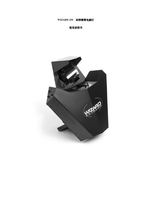
Wizard 250巫师灯使用说明
2.如果灯泡发热,等 5 分钟让它冷却。 戴上护目镜以保护您的眼睛。 3.拆下 6 个螺丝,取出灯具外壳。 4.在变压器上,拆褐色线到变压器端子。这些端子显示在变压器顶部的一个标签上。 5.在镇流器, 拆褐色线到电压端子。 这些端子显示在镇流器的一个标签上。 6.重新安装灯具外壳。
· 如果将 Wizard Extreme 设置为单机操作,又想把它们连接到数据链中,那么在连接数据链之前, 把它们设置为从机。
· 如果将一个 Wizard Extreme 设置为主机,又想将另外一只灯设置为主机,那么在你设置新的主 机之前,你应该把现有的主机设置为从机。 单机操作
Wizard Extreme 可以在音控或自控模式设置为单机操作。这不需要数据链路。 主/从操作
4
5
公
母
1
1
2
2
3
3
4
5
公
母
1
1
2
2
3
3
P/N 11820005
P/N 11820004
P/N 11820006
连接数据链
1.把一根数据电源线连接到控台输出端。如果控台有一个 5 脚输出端,使用一个 5 脚公适配器线到
3 脚母适配器线(P/N 11820005)。
2.将控台出来的数据线连接到控台。把电源线插入灯具的数据输入端。
-3-
·灯具外部温度可达到 60°C(140°F) ,灯泡边上的螺丝温度可达到 90°C(194°F)。 至少要有 5 分钟让灯泡冷却。
·如果外部温度超过 40°C(104°F)时请勿操作灯。 ·请勿直视灯光。 ·在镜头和外壳完全安装前,请勿使用灯具。 ·如果外壳,保护物,镜头受损时,请及时更换。 ·灯泡受损时, 请及时更换。 避免掉落 ·当灯具吊起来时, 确保悬挂装置可承受的重量为所有安装设备的 10 倍以上重量。 ·确保所有外部面板和吊挂硬件都已安全固定,可使用安全缆索等辅助工具保证万无一失。 ·安装维修或拆卸灯具时应确保工作平台安全,并封锁底下的工作区域
HELLA黑魔法LED系列辅助灯说明书

BLACK MAGIC LED SERIES AUXILIARY LIGHTSHELLA legendary lightsOFF-ROAD AUXILIARY LIGHTSTake the adventure with youOffroad – a word which many people associate with adventure and wilderness.For HELLA however, offroad means so much more. For us it means the aspirati-on to keep developing new and even better products that can withstand extreme demands and stresses. The New HELLA BLACK MAGIC LED SERIES, our latest innovation, is proof of this.This auxiliary lights, 100% LED technology, is always going to be an obvious choice for offroad use due to its heavy duty blackout design and compact dimensions.INTRODUCTIONTABLE OF CONTENTSIntroduction . . . . . . . . . . . . . . . . . . . . . . . . . . . .2 Product range . . . . . . . . . . . . . . . . . . . . . . . . . . .4 Flexible installation . . . . . . . . . . . . . . . . . . . . . . . .6 Product overview. . . . . . . . . . . . . . . . . . . . . . . . . .6 Black Magic LED SeriesCube Sets. . . . . . . . . . . . . . . . . . . . . . . . . . . . . .8Mini Lightbars . . . . . . . . . . . . . . . . . . . . . . . . . . 14 Lightbars . . . . . . . . . . . . . . . . . . . . . . . . . . . . . 18 Accessories. . . . . . . . . . . . . . . . . . . . . . . . . . . . 192|3PRODUCT OVERVIEWBLACK MAGIC LED AUXILIARY LIGHTSBLACK MAGIC LEDPRODUCT RANGE AT A GLANCE HELLA BLACK MAGIC LED: REBIRTH OF A LEGEND!CUBES MINI LIGHTBARS LIGHTBARS LEDCubes Kit2.7˝, Flood1FA 358 176-8016.2˝, Flood1FB 358 176-20120˝, Slim1FJ 358 176-30132˝, Slim1FJ 358 176-31140˝, Slim1FJ 358 176-32150˝, Slim1FJ 358 176-33121.5˝, Double1FJ 358 176-4016.2˝, Spot1FB 358 176-2116.2˝Flush Mount,Flood1FB 358 176-2213.2˝, Flood1FA 358 176-8113.2˝, Spot1FA 358 176-8213.2˝, Spot/Flush1FA 358 176-831Single Single|54BLACK MAGIC LEDSee on page 16FLEXIBLE INSTALLATIONThe long included cable allows easy vehicle mounting. TheMini Lightbar, Cubes and Lightbars comes as a Flood orSpot light and can be upright or pendant mounted or integ-rated into the body work or bumper. This light bar is readyto brighten up your next adventure.See on page 8See on page 16See on page 8 See on page 12For further information on each product, see general overview on page 8-19SPECIFICATIONS➔Offers some of the toughest dust / water protection on themarket➔Full blackout appearance ➔Including mounting hardware ➔Sleek design➔Specially developed reflector design for homogeneousilluminationBLACK MAGIC LED SERIESTHE NEW FULL BLACKOUT APPEARANCEL E D| 76Technical data Rated voltage Multi-voltage Operating voltage 10 – 30 VCurrent consumption 2.7˝: 1.8 A (12 V) / 0.9 A (24 V) 3.2˝: 3.4 A (12 V) / 1.6 A (24 V)Power consumption 20 W (2.7˝)40 W (3.2˝)Light function Spot or Flood Light source LED Colour temperature 5,700 KelvinMaterial Aluminium, black stainless steel bracket Weight350 g (single light 2.7˝)358 g (single light 3.2˝)372 g (flush mount 3.2˝ single)Protection class IP 68, IP 69K EMC protection ECE-R10Mounting Upright / pendant or flush mounting Connection DT connector Amount of LEDs 4Length of cable500 mm cable with DT connector + short adapter harness Light performance (effective)1,400 lm (2.7˝)3,000 lm (3.2˝)Application For Offroad vehicles such as 4x4‘s,SUV‘s, Pick-ups, Buggy‘s, Quads, Trikes, Snow mobiles, Construction Machinery, TractorsBLACK MAGIC LED CUBESFull blackout appearanceBlack holder for mounting options upright and pendantEdgeless design avoids sticking of dust and rainSmart constructed reflector without glare effectSPECIFICATIONS➔Full blackout appearance including black brackets➔Sleek design eliminates dust and dirt from being lodged inedges➔Each kit includes the wiring harness with DT connector,switch, connector and relays (easy to install)➔Compact design for universal installationHELLA‘s Black Magic Cubes are available in 2 sizes, 2.7˝and 3.2˝. Distinguished by the full blackout appearance andsleek design makes this light stand out from the crowd.Black Magic Cubes received the highest dust and waterproofrating. They come in kits of 2 lights including a wiring harnesswith DT connector, switch, connector and relays making themeasy to install. The 3.2˝ is available in Flood or Spot light and canbe upright or pendant mounted or integrated into the body workor bumper. HELLA‘s Black Magic Cubes are ready to brighten upyour next adventure.BLACK MAGIC LED SERIESCUBE SETDimensional sketches of the BLACK MAGIC LED CUBESLED Cube 2.7˝ (surface mount version)LED Cube 3.2˝ (flush mount version)LED Cube 3.2˝ (surface mount version)LED|9812BLACK MAGIC LED CUBESLED Cube KIT 2.7˝, Flood LED Cube KIT 3.2˝, FloodLED Cube KIT 3.2˝, Spot LED Cube KIT 3.2˝, Flood / Flush APPLICATION EXAMPLES1) 2 x Black Magic Cube: A-Pillar mount – angled outside2) 2 x Black Magic Cube: Bumper mount ILLUMINATIONThe light distribution charts show the ranges of two lights (a pair).Scope of delivery DescriptionPart numberLED Cube Kit 2,7˝ (Flood)Includes: (2) LED spotlights, (1) relay, (1) switch and mounting instructions, (1) wiring harness with DT connector1FA 358 176-801LED Cube Kit 3.2˝ (Flood)Includes: (2) LED spotlights, (1) relay, (1) switch and mounting instructions, (1) wiring harness with DT connector1FA 358 176-811LED Cube Kit 3.2˝ (Spot)Includes: (2) LED spotlights, (1) relay, (1) switch and mounting instructions, (1) wiring harness with DT connector1FA 358 176-821LED Cube Kit 3.2˝ (Flood / Flush)Includes: (2) LED spotlights, (1) relay, (1) switch and mounting instructions, (1) wiring harness with DT connector 1FA 358 176-831PROGRAM OVERVIEW|1110Technical dataRated voltage Multi-voltageOperating voltage10 – 30 VCurrent consumption 2.6 A (12 V) / 1.3 A (24 V)Power consumption30 WLight function Spot or FloodLight source LEDColour temperature5,700 KelvinMaterial Aluminium, black stainless steel bracket Weight470 g (surface mount version)505 g (flush mount version) Protection class IP 68, IP 69KEMC protection ECE-R10Mounting Upright / pendant or flush mounting Connection800 mm cable with open ends Amount of LEDs6Light performance1,600 lmApplicationFor Offroad vehicles such as 4x4‘s,SUV‘s, Pick-ups, Buggy‘s, Quads, Trikes,Snow mobilesSleek design avoids sticking ofdust and rain Aerodynamic designFull blackout appearance Compact design applicablefor multiple locationsBLACK MAGIC LED MINI LIGHT BARSSPECIFICATIONS➔Offers some of the toughest dust / water protection on themarket➔Full blackout appearance ➔Including mounting hardware ➔Sleek designBLACK MAGIC LED SERIESMINI LIGHTBARSDistinguished by the full blackout appearance and sleek design that stands out from the crowd with unmatched light output. This product family scored the highest dust / waterproof rating and the edgeless design prevents dust deposits from settling along edges. The long included cable allows for easy vehicle mounting. The Mini Lightbar comes as a Flood or Spot light and can be upright or pendant mounted or integrated into the body work or bumper. This light bar is ready to brighten up your next adventure.Dimensional sketches of the BLACK MAGIC LED MINI LIGHT BARS Surface mount versionsFlush mount versionL E D| 131240608010012020METERSLUX1001051200300400100METERSLUX100105140608010012020METERSLUX1001051 ILLUMINATIONThe light distribution charts show the ranges of two lights.Black Magic Mini Lightbar 6.2˝, FloodBlack Magic Mini Lightbar 6.2˝, SpotBlack Magic Mini Lightbar 6.2˝Flush Mount, FloodBLACK MAGIC LED MINI LIGHT BARSScope of deliveryDescriptionPart numberLED Mini Lightbar 6.2˝ (Flood)Includes: (1) LED spotlight, (1) mounting hardware,(1) mounting instructions1FB 358 176-201LED Mini Lightbar 6.2˝ (Spot)Includes: (1) LED spotlight, (1) mounting hardware,(1) mounting instructions1FB 358 176-211LED Mini Lightbar 6.2˝ Flush Mount (Flood)Includes: (1) LED spotlight, (1) mounting frame and screws,(1) mounting instructions1FB 358 176-221APPLICATION EXAMPLEPROGRAM OVERVIEW1) 2 x Black Magic Mini Lightbar: Front bumper mount| 1514Technical dataVersionLED Slim LightbarLED Double Lightbar 20˝32˝40˝50˝21.5˝Rated voltage Multi-voltage Operating voltage 10 – 30 V Current consumption 5.7 – 8 A (12 V)2.8 – 3.9 A (24 V)8.9 – 12.5 A (12 V)4.2 – 6.1 A (24 V)10.1 – 14.9 A (12 V)4.9 – 7.8 A (24 V)11.8 – 19.2 A (12 V)5.6 – 10.1 A (24 V)6.7 – 14.6 A (12 V)3.5 –7.2 A (24 V)Power consumption 105 W165 W 210 W270 W200 WLight function / Light sourceSpot (offroad only) / LEDColour temperature 5,700 KelvinMaterial Aluminium, black stainless steel bracketWeight1,400 g1,780 g2,400 g3,000 g2,420 gProtection class/ EMC protection IP 68, IP 69K, ECE-R10Mounting Upright / pendant Connection 2,000 mm cable with open endsAmount of LEDs 2133425440Light performance (effective)max. 6,000 lmmax. 9,000 lmmax. 12,000 lmmax. 15,000 lmmax. 11,000 lmEdgeless design avoids sticking of dust and rainFull blackout appearanceSleek designSlim design applicable for multiple locationsBLACK MAGIC LED LIGHT BARSBlack Magic Lightbar 20˝ (Slim)BLACK MAGIC LED SERIESLIGHTBARSSPECIFICATIONS➔Full blackout appearance➔Including black brackets➔Sleek design➔Temperature Control System➔Intense light outputThe HELLA Black Magic Lightbars offer driving beams withvery powerful lightoutput up to 15,000 lumen, ideal foroff-road situations where you need this the most. They have arecognizable and attractive full blackout appearance, slim andedgeless design. Typical applications would be installations asHood, Bumper, Ground Bumper and Roof Lightbars.The product scored the highest dust / waterproof rating andthe edgeless design prevents dust deposits from settlingalong edges.The extra long 2 meter cable allows easy mounting on yourvehicle. The Black Magic Lightbars have an integrated thermalsensor that adapts to the ambient temperature. This newfeature not only prevents overheating or LED failure, butalso increases light output when the ambient temperatureis low. In this way the user is given the optimum light underall conditions.Dimensional sketches of the BLACK MAGIC LED LIGHT BARSBlack Magic Lightbar 40˝ (Slim)Black Magic Lightbar 21.5˝ (Double)Black Magic Lightbar 32˝ (Slim)Black Magic Lightbar 50˝ (Slim)LED|1716Black Magic Lightbar 20˝, SlimBlack Magic Lightbar 32˝, SlimBlack Magic Lightbar 40˝, SlimBlack Magic Lightbar 21.5˝, DoubleBlack Magic Lightbar 50˝, SlimILLUMINATIONThe light distribution charts show the ranges of two lights.APPLICATION EXAMPLESIllumination shown in photo made by one: 1 x 40˝ Black Magic Slim Lightbar (Hood mount)BLACK MAGIC LED LIGHT BARSScope of deliveryDescriptionPart numberLED Slim Lightbar 20˝Includes: (1) LED spotlight, (1) mounting hardware,(1) mounting instructions1FJ 358 176-301LED Slim Lightbar 32˝Includes: (1) LED spotlight, (1) mounting hardware,(1) mounting instructions1FJ 358 176-311LED Slim Lightbar 40˝Includes: (1) LED spotlight, (1) mounting hardware,(1) mounting instructions1FJ 358 176-321LED Slim Lightbar 50˝Includes: (1) LED spotlight, (1) mounting hardware,(1) mounting instructions1FJ 358 176-331LED Double Lightbar 21.5˝Includes: (1) LED spotlight, (1) mounting hardware,(1) mounting instructions1FJ 358 176-401Scope of deliveryDescriptionPart numberSlim Lightbar Back Side Mounting Bracket + screws set (2 pcs),recommended to be used for extra support for 40˝ and50˝ Lightbar8HG 358 176-341PROGRAM OVERVIEWACCESSORIES| 1918HELLA Asia Singapore Pte Ltd Regional Headquarters Asia Pacific Independent Aftermarket2 International Business Park#02-12 The StrategySingapore 609930Tel: +65 6854 7300Fax: +65 6854 7302E-mail:***************** Internet: © HELLA GmbH & Co. KGaA, Lippstadt9Z2 999 142-852 J01791/KB/09.21/0.1 Printed in GermanySubject to technical and price modifications. /offroad。
魔灯Dual ISO的理解与设置探索(原创)
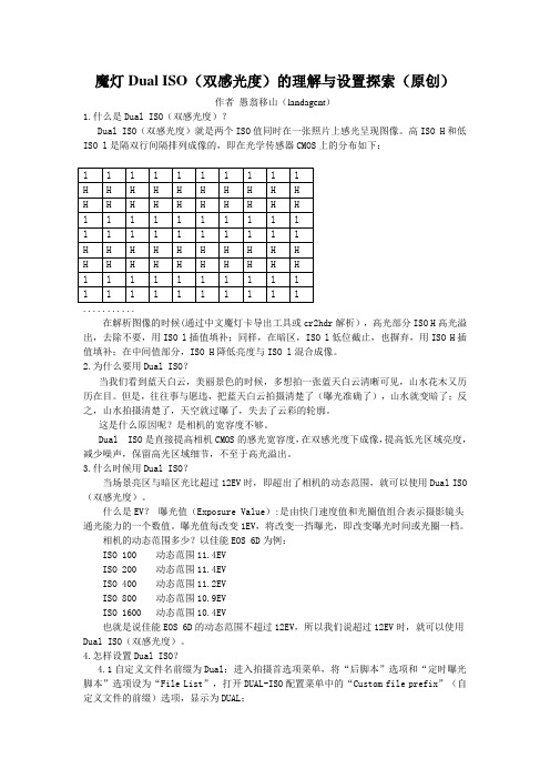
魔灯Dual ISO(双感光度)的理解与设置探索(原创)作者愚翁移山(landagent)1.什么是Dual ISO(双感光度)?Dual ISO(双感光度)就是两个ISO值同时在一张照片上感光呈现图像。
高ISO H和低ISO l是隔双行间隔排列成像的,即在光学传感器CMOS上的分布如下:l l l l l l l l l lH H H H H H H H H HH H H H H H H H H Hl l l l l l l l l ll l l l l l l l l lH H H H H H H H H HH H H H H H H H H Hl l l l l l l l l ll l l l l l l l l l...........在解析图像的时候(通过中文魔灯卡导出工具或cr2hdr解析),高光部分ISO H高光溢出,去除不要,用ISO l插值填补;同样,在暗区,ISO l低位截止,也摒弃,用ISO H插值填补;在中间值部分,ISO H降低亮度与ISO l混合成像。
2.为什么要用Dual ISO?当我们看到蓝天白云,美丽景色的时候,多想拍一张蓝天白云清晰可见,山水花木又历历在目。
但是,往往事与愿违,把蓝天白云拍摄清楚了(曝光准确了),山水就变暗了;反之,山水拍摄清楚了,天空就过曝了,失去了云彩的轮廓。
这是什么原因呢?是相机的宽容度不够。
Dual ISO是直接提高相机CMOS的感光宽容度,在双感光度下成像,提高低光区域亮度,减少噪声,保留高光区域细节,不至于高光溢出。
3.什么时候用Dual ISO?当场景亮区与暗区光比超过12EV时,即超出了相机的动态范围,就可以使用Dual ISO (双感光度)。
什么是EV?曝光值(Exposure Value):是由快门速度值和光圈值组合表示摄影镜头通光能力的一个数值。
曝光值每改变1EV,将改变一挡曝光,即改变曝光时间或光圈一档。
相机的动态范围多少?以佳能EOS 6D为例:ISO 100 动态范围11.4EVISO 200 动态范围11.4EVISO 400 动态范围11.2EVISO 800 动态范围10.9EVISO 1600 动态范围10.4EV也就是说佳能EOS 6D的动态范围不超过12EV,所以我们说超过12EV时,就可以使用Dual ISO(双感光度)。
Magic Lantern(魔灯) v2.3用户指南
Magic Lantern v2.3 - User's Guide魔术灯2.3版用户指南资料来源:http://wiki.magiclantern.fm/userguide内容下载时间:2014年2月中文翻译:蜗居客Features产品特点●Audio: disable AGC, audio meters, manual audio controls, selectable input source (internal,internal+external, external stereo, balanced), audio monitoring via A/V cable.音频:使用自动增益控制、音频表、手动音频控制、可选择的输入源(内部,内部+外部,外部立体声,平衡状态)、通过A / V电缆监控音频。
●Exposure helpers: ETTR, zebras, false color, histogram, waveform, spotmeter, vectorscope.曝光辅助:向右曝光、斑马图、伪彩色、直方图、波形图、点测光表、矢量图。
●Focus tools: focus peaking, zoom while recording, trap focus, rack_focus, follow_focus,stack_focus.对焦工具:峰值对焦、录像中变焦、陷阱对焦、焦点偏移、跟踪对焦。
●Movie helpers: Bitrate control, movie logging (Exif-like metadata), auto-restart after bufferoverflow or 4 GB limit, HDR video, advanced FPS control.摄像辅助:比特率控制、录像记录(EXIF类型的元数据)、缓冲区溢出或因4 GB的限制中断后自动重新启动录像过程、高动态视频、高级每秒帧数控制。
魔灯中文说明书
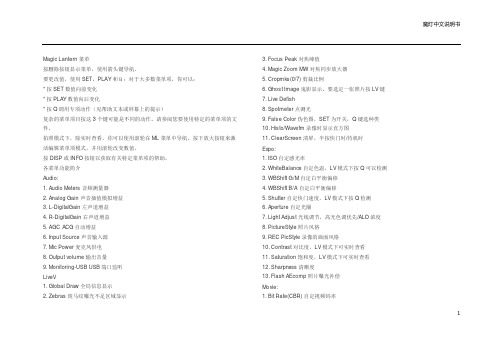
Magic Lantern 菜单按删除按钮显示菜单,使用箭头键导航。
要更改值,使用SET,PLAY和Q:对于大多数菜单项,你可以:* 按SET数值向前变化* 按PLAY数值向后变化* 按Q调用专项动作(见帮助文本或屏幕上的提示)复杂的菜单项目按这3个键可能是不同的动作。
请参阅您要使用特定的菜单项的文件。
拍照模式下,除实时查看,你可以使用滚轮在ML菜单中导航。
按下放大按钮来激活编辑菜单项模式,并用滚轮改变数值。
按DISP或INFO按钮以获取有关特定菜单项的帮助。
各菜单功能简介Audio:1. Audio Meters 音频测量器2. Analog Gain 声音插值模拟增益3. L-DigitalGain 左声道增益4. R-DigitalGain 右声道增益5. AGC ACG自动增益6. Input Source 声音输入源7. Mic Power 麦克风供电8. Output volume 输出音量9. Monitoring-USB USB端口监听LiveV1. Global Draw 全局信息显示2. Zebras 斑马纹曝光不足区域显示3. Focus Peak 对焦峰值4. Magic Zoom MW对焦同步放大器5. Cropmks(0/7) 剪裁比例6. Ghost Image 鬼影显示,要选定一张照片按LV键7. Live Defish8. Spotmeter 点测光9. False Color 伪色图,SET为开关,Q键选种类10. Histo/Wavefm 录像时显示直方图11. ClearScreen 清屏,半按快门时/待机时Expo:1. ISO 自定感光率2. WhiteBalance 自定色温,LV模式下按Q可以检测3. WBShift G/M 自定白平衡偏移4. WBShift B/A 自定白平衡偏移5. Shutter 自定快门速度,LV模式下按Q检测6. Aperture 自定光圈7. Light Adjust 光线调节,高光色调优先/ALO浓度8. PictureStyle 照片风格9. REC PicStyle 录像的画面风格10. Contrast 对比度,LV模式下可实时查看11. Saturation 饱和度,LV模式下可实时查看12. Sharpness 清晰度13. Flash AEcomp 照片曝光补偿Movie:1. Bit Rate(CBR) 自定视频码率12. BuffWarnLevel 缓冲区报警设置3. Time Indicator 时间指示器4. Bitrate Info 比特率信息5. Movie Logging 生成短片文件日志6. Movie Restart 录像中断时(29分29秒)重新录像7. MovieModeRemap 视频模式映射8. REC/STBY notif 录制备用通知9. Movie REC key 录制热键设置10. Force LiveView 强制保持实时显示模式11. Force HDMI-VGA 强制同步输出HDIM或VGA信号Shoot:1. HDR Bracketing HDR档次,Q关闭/SET快门数/PLAY键设置EV值。
魔灯中文说明书

Magic Lantern 菜单按删除按钮显示菜单,使用箭头键导航。
要更改值,使用SET,PLAY和Q:对于大多数菜单项,你可以:* 按SET数值向前变化* 按PLAY数值向后变化* 按Q调用专项动作(见帮助文本或屏幕上的提示)复杂的菜单项目按这3个键可能是不同的动作。
请参阅您要使用特定的菜单项的文件。
拍照模式下,除实时查看,你可以使用滚轮在ML菜单中导航。
按下放大按钮来激活编辑菜单项模式,并用滚轮改变数值。
按DISP或INFO按钮以获取有关特定菜单项的帮助。
各菜单功能简介Audio:1. Audio Meters 音频测量器2. Analog Gain 声音插值模拟增益3. L-DigitalGain 左声道增益4. R-DigitalGain 右声道增益5. AGC ACG自动增益6. Input Source 声音输入源7. Mic Power 麦克风供电8. Output volume 输出音量9. Monitoring-USB USB端口监听LiveV1. Global Draw 全局信息显示2. Zebras 斑马纹曝光不足区域显示3. Focus Peak 对焦峰值4. Magic Zoom MW对焦同步放大器5. Cropmks(0/7) 剪裁比例6. Ghost Image 鬼影显示,要选定一张照片按LV键7. Live Defish8. Spotmeter 点测光9. False Color 伪色图,SET为开关,Q键选种类10. Histo/Wavefm 录像时显示直方图11. ClearScreen 清屏,半按快门时/待机时Expo:1. ISO 自定感光率2. WhiteBalance 自定色温,LV模式下按Q可以检测3. WBShift G/M 自定白平衡偏移4. WBShift B/A 自定白平衡偏移5. Shutter 自定快门速度,LV模式下按Q检测6. Aperture 自定光圈7. Light Adjust 光线调节,高光色调优先/ALO浓度8. PictureStyle 照片风格9. REC PicStyle 录像的画面风格10. Contrast 对比度,LV模式下可实时查看11. Saturation 饱和度,LV模式下可实时查看12. Sharpness 清晰度13. Flash AEcomp 照片曝光补偿Movie:1. Bit Rate(CBR) 自定视频码率12. BuffWarnLevel 缓冲区报警设置3. Time Indicator 时间指示器4. Bitrate Info 比特率信息5. Movie Logging 生成短片文件日志6. Movie Restart 录像中断时(29分29秒)重新录像7. MovieModeRemap 视频模式映射8. REC/STBY notif 录制备用通知9. Movie REC key 录制热键设置10. Force LiveView 强制保持实时显示模式11. Force HDMI-VGA 强制同步输出HDIM或VGA信号Shoot:1. HDR Bracketing HDR档次,Q关闭/SET快门数/PLAY键设置EV值。
佳能5D2魔灯中文固件安装方法

如果以前安装过英文老版本,请先用PC格式化SD卡或CF卡,再重新安装中文版。
(切记用
PC格式化)
第一步:
首先将相机设为M模式,如下图:
第二步:
按MENU键,进入菜单,使用相机格式化功能格式化SD卡,菜单位置如下:
进入格式化菜单后选择“低级格式化”,点确认,开始格式化SD卡,如下图。
第三步:
将SD卡插入读卡器,将压缩文件包中的文件拷到SD卡,拷贝完后,SD卡根目录如下图。
第四部:
将SD卡插回相机,按MENU键,进入固件升级菜单,菜单位置如下:
进入固件升级菜单后,点击确定开始升级,如下图
升级过程不要按任何按键(大约5-10秒左右),直到出现绿色的字。
关键:出现绿色字后,30秒内一定要按电源键关机,否则绿色字消失,会进入自动卸载流程,白装了,切记。
注:按垃圾桶删除键进入魔灯界面半按快门键退出魔灯界面
Lifeview模式下,按INFO切换取景模式,多按几次可进入魔灯取景模式。
(学习的目的是增长知识,提高能力,相信一分耕耘一分收获,努力就一定可以获得应有的回报)。
GODOX LED钻光环灯LR150说明书

Shenzhen, China Thank you for purchasing this Godox Product!This LED Ring Light LR150 is suitable for almost all shooting occasions, which can offer lighting for live, make up, portrait shooting, video, wedding, catchlight, etc.Features:● Bicolor adjustment: steplessly adjust color temperature from 3000K-6000K ● Freely adjust brightness from 1% to 100%● Included an adapter and a smartphone holderForwardTechnical DataLED Ring Light DC Power Supply USB Power Output PowerColor Temperature100% Brightness(LUX)0.5m≈Light Brightness Range CRI TLCILED Beads Quantity Operation Temperature Dimension WeightLR15024V/2A 5V/2A Approx. 38W 3000K-6000K 14001%~100%> 90> 90336-10~40°C 455x555x45mm Black version: 880g Pink version: 870gWarningAlways keep this product dry. Do not use in rain or in damp conditions.Do not disassemble. Should repairs become necessary, this product must be sent to an authorized maintenance center.Keep out of reach of children.As this product do not have waterproof function, please take measures of waterproof in rainy or damp environment.Do not use the light in the presence of flammable gases, chemicals and other similar materials. In certain circumstance, these materials may be sensitive to the strong light emitting from this flash unit and fire or electromagnetic interference may result.LED RING LIGHTMade in ChinaAdd: Building 2, Yaochuan Industrial Zone, Tangwei Community, Fuhai Street, Bao’an District,Tel: +86-755-29609320(8062) Fax: +86-755-25723423 E-mail: *************** GODOX Photo Equipment Co., Ltd.705-LR1200-01。
Polaris AfterDark 灯光驱动器说明书

AfterDark I M P O RTA N T I N F O R M AT I O NImportant InformationFollow these simple guidelines, to protect against injury and prolong the life of your Polaris AfterDark®light driver.•The light driver operates on 120VAC, 60Hz.Do not attempt to alter the unit to operate on any other voltage.•Always turn off the power supply to the light driver before removing the cover.•Keep the ventilation slots at the bottom of the unit clear of leaves and debris.•Do not sit or stand on the light driver, or place anything on top of it.•Do not submerge the light driver in water or operate it while it is buried in snow.The unit must be ventilated at all times to avoid damage and voiding of the warranty.•Do not allow children to play with the light driver.•The light driver is equipped with a metal-halide lamp which builds brightness gradually.It may take as long as 2 minutes for the light intensity to peak.If the light driver is shut off after warming up, it may take up to two minutes to regain full intensity.•Use only Polaris lamp #AD300 to replace the bulb in this light driver.Failure to do so could result in bodily injury or damage to the light driver.•Install the light driver at least five feet (1.5 meters) from the pool, spa or hot tub.•The Polaris After Dark light driver is designed to work with genuine Polaris fiber optic cable only.Polaris is not responsible for damage to non-Polaris fiber optic cable.For customer service or support:• Please mail Warranty Card immediately.• For on-line support:• To contact Polaris:US and Canada Australia EuropeCustomer Service Unit 4, 19-21 Gibbes Street,C/Osana s/n.2620 Commerce Way Chatswood, NSW 2067(Pol.End.El Ramassar),Vista, CA 92081-84381-300-POLARIS98520 Les Franqueses del Vallés1-800-822-7933ACN 080 168 092Barcelona, Spain+34 93 840 25 85Congratulations on the purchase of your new fiber optic lighting system and thank you for choosing Polaris.The Polaris AfterDark ®light driver is designed to provide safe,beautifully colored lighting and years of trouble-free service.The brightness of a fiber optic lighting system is determined by many factors including the cable length, the size of the pool, the color of the pool’s interior, and the amount of ambient light in the pool area.If you have purchased the AD150 equipped with a Color Wheel, you will notice variations in color intensity in different colors.Each color emits a different level of brightness, white is the brightest and magenta is the least bright.Always insist on genuine Polaris replacement parts.Non-Polaris parts are not made to our specifications and can adversely affect the operation of your light driver.Introduction1.Cover2.Chassis Assembly3.Installation Base4.Parts Baga.Color wheel control plugb.Manifoldc.4" filler cablesd.Screwse.ClampPolaris After Dark CompletePrepare the ConduitRun separate conduits for each lens e only sweep ells or heat-bent PVC, not standard 90°plumbing fittings.Center the fiber optic conduits where the installation base will be placed.Remove the cover and separate the chassis assembly from the installation ing the handles, lift the chassis off the base and place it in a safe location until ready to complete electrical connections.Cut the conduit so it protrudes 1/3 of the way into the installation base.Guide the electrical conduit through the small hole in the installation base until it extends 1" to 4" above the base.Installation Instructions1Install the BaseIf installing underwater lights, install the Universal Fiber Lens (part #AD10) first and then install the light driver.If installing a light kit, install the fiber first and then install the light driver.Remove the installation base to access conduit ends.1.Feed the fiber optic cable through the conduits.Measure enough cable for a service loopof at least 18" but no more than 36" at the light driver.2.Strip the fiber casing back 8-10" to expose the bare fibers.Hold the tips of the fibercables even and insert them through the fiber manifold body starting at the compression fitting.Push the fiber through until the bare fibers extend 3-4”past the manifold opening.3.Secure the loose fibers with the clamp provided, making sure that the individual fibersextend at least 1”beyond the e the Polaris Hot Knife (part #AD25) to trim the fibers until the ends are clean and even with the clamp.4.Remove the clamp and slide the fibers back so that they are flush with themanifold opening.5.Hand tighten the compression fitting.If the fitting does not hold the fiber casings securely,loosen the fitting, insert the filler cables provided and re-tighten the fitting.26.Insert the fiber manifold into the installation base from the bottom and secure it at the topwith the manifold nut.7.Place the installation base over the ends of the fiber optic conduits while guiding theelectrical conduit through the smaller hole.8.Backfill dirt around the installation base to secure it.Ground level should be at least 1"below the top of the base.Install Chassis AssemblyUsing the handles, lift the chassis assembly onto the installation base and secure.To connect the electrical supply, check the model number of your light driver and refer to the wiring connection requirements below for the proper configuration.Position and secure the cover onto the installation base/chassis assembly.3OperationParts Bag 1AD210Cover12AD300Lamp/Reflector Assembly 13AD305Lamp Only, 150W H.I.D 14AD310Lamp Bracket15AD325Lamp Wire/Socket Assembly 16AD320Heat Filter Assembly 17AD435Fuse, Color Wheel18AD430Color Wheel Control Board 19AD640Fuse Holder, Main Power 110AD650Fuse, Main Power 111AD410Color Wheel Retainer 112AD400Color Wheel Assembly 113AD630Fan114AD620Switch, Color wheel Power 3-way 115AD610Switch, Main Power 2-way 116AD420Color Wheel Motor117AD500Color Wheel Power Connector 118AD100Manifold Assembly1AD10UFL Waterproof Lens Housing, Universal, 1-1/2" MIP AD15Wireless RemoteNo.P a rt DescriptionQtyAfterDarkExploded Parts DiagramIf the Polaris After Dark displays any of the following actions, adjustments may be necessary to restore performance.Refer to the exploded par ts diagram for par t numbers indicated in parenthesis.Action:The light driver does not come on. Solution: 1.Verify that unit is turned on.2.If using an external remotecontroller to activate the120VAC supply, make surethat the relay controlling thelight driver is on andsupplying power.3.Locate the Ground FaultCircuit Interrupter (G.F.C.I.)protecting the circuit andverify proper operation byfollowing the T est and Resetinstructions on the G.F.C.I.4.Verify that the in-line fuse (#8),located on the chassis, is intact. Action:The color wheel does not rotate. Solution: 1.Verify that the color switchis positioned for slow orfast operation.2.If using a Polaris Solcontroller or other externalremote controller, make surethe relay controlling it is onand supplying power.3.Check the spade connectorson the color wheel circuitboard (#7) and verify that theyare connected properly. Action:The light output has dimmedover time.Solution: 1.T urn off the power to the lightdriver and check for dirt buildup on the manifold tip, colorwheel, and heat filter.Cleanas necessary.2.Check the universal fiber lensto make sure it is not filledwith water.The area aroundthe fiber tip inside the lensmust be dry.Action:The light driver is turned on butit continues to cycle on and off. Solution: 1.With the unit operating, listenfor the cooling fan (#13).If it isnot heard, it may be blocked.T urn off the main power to thelight driver, remove the cover,clear the fan of any debrisand check its wiring.TroubleshootingModel SpecificationsModel:AD150 (Colored Light)Model:AD151 (White Light)Lamp Type:Metal-Halide Lamp, CDM Lamp T ype:Metal-Halide Lamp, CDM Replacement Lamp P/N:AD300Replacement Lamp P/N:AD300 Colors:9No ColorsC/W Motor:12 VDC, 2 speeds No Color Wheel MotorVoltage:120 VAC, 60 HZ Voltage:120 VAC, 60HZPower Consumption:200 Watts Max Power Consumption:200 Watts Max Start Current Load:4.4 Amps Start Current Load:4.4 AmpsRun Current Load:1.8 Amps Run Current Load:1.8 Amps Enclosure Material:Luran®S ASA Enclosure Material:Luran®S ASA Ventilation:110 cu.ft./min.Ventilation:110 cu.ft./min.Weight:21 lbs.Weight:20 lbs.©2004 Polaris Pools Systems, Inc.All Rights Reserved.TL-600 1/04。
GODOX Round RGB Mini Creative Light R1说明书
- 15 -
Contents
13 Forward 14 Warning 17 Names of Parts 18 Included Items 18 Separately Sold Accessories 19 Battery 19 Operation 23 Technical Data 24 Maintenance
OFF ON
1.2 Mode Selection: Bicolor mode/Colorful mode/Situational special effects mode Press MOD button to switch different modes: CCT displayed on the screen means bicolor mode, HIS displayed on the screen means colorful mode and 1 to14 means situational special effects mode.
- 16 -
Names of Parts
01. LED Beads 02. Diffuser 03. 1/4" Mounting Socket 04. Type-C USB Charging Port 05. MIC 06. Power Switch 07. Mode SБайду номын сангаасlection Button 08. FN Multifunctional Select Dial 09. Display Screen 10. Light Brightness Select Dial
HARMAN 800W LED ERA 800 Profile 移动头灯说明书
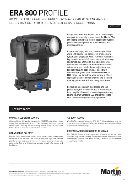
800 WATT LED LIGHT SOURCEWith an efficient 800 watt light source, the ERA 800 Profile delivers more output than similar-sized fixtures. Fully electronic dimming ensures extremely fast strobing, instant intensity control, and a flat, consistent field that can be maintained down to zero percent.GREAT COLOR PALETTEPrecise color temperature control with variable color temperature correction (CTO). Vibrant CMY color mixing from light and smooth pastels to rich, saturated primaries. The color wheel produces nice color splits, fast color bumps and extends overall color gamut and brightness.1:8 ZOOM RANGEWith 7 to 56 degrees of zoom, the ERA 800 Profile works great even on larger trim heights. Zooming is fast and accurate and maintains a high output throughout the range.COMPACT AND DESIGNED FOR THE ROADThe ERA 800 Profile is a very compact and low weight for its class making it easy to handle and rig. The modular design makes accessing and replacing of effects safe, quick, and easy – modules can be swapped in less than a minute.KEY MESSAGES Designed to fulfill the demand for an ultra-bright, compact, tour-worthy moving head, the Martin ERA 800 Profile combines a feature-loaded and rugged, yet cost-efficient profile for entertainment and rental applications.It features a highly efficient, super-bright 800W white LED engine that produces a bright, sharp 6,500K gobo projection with a flat field. Additional key benefits include 1:8 zoom, electronic dimming and strobe, full CMY color mixing and separate color wheel, variable color temperature control, animation wheel, iris for beam adjustment and fixed and rotating gobo wheels, loaded withuser-favorite gobos from the renowned Martin MAC range that includes a wide variety of effects, especially when combined with the two included rotating prisms and soft and heavy frost filters. Perfect for big, stadium-sized stage and live productions, the Martin ERA 800 Profile is idealfor a long list of scenarios, requiring an extremely bright, yet truly versatile LED profile that offers near limitless design and usage potential.MODELS• ERA 800 Profile in cardboard box .............................P/N 9025123581• ERA 800 Profile White in cardboard box ..................P/N 9025123582• Flightcase, two unit, for 2 x ERA 800Performance / Profile ...................................................P/N 91512255 INCLUDED ITEMS• Two omega brackets with 1/4 turn fastenersfor rigging clamp attachment .................................2 x P/N 91602001 RELATED ITEMS• Martin Companion software suite(incl. firmware uploader) .......Free download from • Martin Companion Cable USB/DMXhardware interface .......................................................P/N 91616091• Martin RDM 5.5 Splitter ................................................P/N 90758150CONVERSION KITS• Framing Module(converts ERA 800 Profile to Performance) ..............P/N 5125961-00• Gobo Wheel 3 Effects Module(converts ERA 800 Performance to Profile) ..............P/N 5131799-00OPTICAL ACCESSORIES• CRI Boost Filter(CRI >80, installs on gobo wheel) ..............................MAR-91614059POWER INPUT CABLES• Power Input Cable, H07RN-F, 2.5 mm 2, 14 AWG, bare ends to TRUE1 NAC3FX-W(female), 1.5 m (4.9 ft.) ..................................................P/N 91611797• Power Input Cable, H07RN-F, 2.5 mm 2, 14 AWG, bare ends to TRUE1 NAC3FX-W(female), 5 m (16.4 ft.) ...................................................P/N 91611786• Power Input Cable, SJOOW, 12 AWG, bare ends to TRUE1 NAC3FX-W(female), 1.5 m (4.9 ft.) ..................................................P/N 91610173• Power Input Cable, SJOOW, 12 AWG, bare ends to TRUE1 NAC3FX-W(female), 5 m (16.4 ft.) ...................................................P/N 91610174POWER RELAY CABLES, 16 A, FOR RELAYING POWER TO A SECOND FIXTURE AT 200 - 230 V MAINS POWER• Power Relay Cable, H07RN-F, 2.5 mm 2,TRUE1 to TRUE1, 0.45 m (1.5 ft.) ..................................P/N 91611784• Power Relay Cable, H07RN-F, 2.5 mm 2,TRUE1 to TRUE1, 1.2 m (3.9 ft.) ....................................P/N 91611785• Power Relay Cable, H07RN-F, 2.5 mm 2,TRUE1 to TRUE1, 2.5 m (8.2 ft.) ....................................P/N 91611796• Power Relay Cable, SJOOW, 12 AWG,TRUE1 to TRUE1, 0.45 m (1.5 ft.) ..................................P/N 91610170• Power Relay Cable, H07RN-F, 2.5 mm 2,TRUE1 to TRUE1, 1.2 m (3.9 ft.) ....................................P/N 91610171• Power Relay Cable, H07RN-F, 2.5 mm 2,TRUE1 to TRUE1, 2.5 m (8.2 ft.) ....................................P/N 91610172POWER CONNECTORS• Cable Connector, Neutrik powerCON TRUE1NAC3FX-W TOP (female) .........................................P/N 91611789HU • Cable Connector, Neutrik powerCON TRUE1NAC3FX-W TOP (male) ............................................P/N 91611788HUINSTALLATION HARDWARE• Hand-coupler Clamp ....................................................P/N 91602005• Safety Cable, SWL 60 kg,BGV C1 / DGUV 17, black ..............................................P/N 91604006• Safety Cable, SWL 60 kg,BGV C1 / DGUV 17, silver ..............................................P/N 91604007DYNAMIC EFFECTSElectronic 'shutter' effect......................S trobe effect, pulse effects, instantopen and blackoutElectronic dimming ...............................0 - 100%, four dimming curve options Color mixing ..........................................CMY, independently variable 0-100% Color temperature control ....................Variable 6500 - 2700 KColor wheel............................................6 color filters plus openRotating gobo whee l ..............................6 gobos plus open, wheel rotation, goborotation, indexing and shakeSecond rotating gobo whee l ..................6 gobos plus open, wheel rotation, goborotation, indexing and shakeStatic gobo wheel ..................................7 gobos plus open, wheel indexing,rotation and shakeGobo animation......................................A nimation wheel, indexing, continuousrotation with variable speed anddirection Iris..........................................................0-100%Zoom ......................................................Motorized Focus......................................................Motorized Prism......................................................2 rotating/indexing prisms(4-facet circular and 6-facet linear) Frost.......................................................Soft frost effect and heavy frost effect Pan .........................................................540°, coarse & fine control and speed Tilt ..........................................................260°, coarse & fine control and speedCONTROL AND PROGRAMMINGControl options ......................................DMX16-bit control .........................................Dimming, CMY, CTO, pan and tilt Setting and addressing .........................Control panel with backlit LCD display DMX channels, ERA 800 Performance..42DMX channels, ERA 800 Profile (36)DMX compliance ITT DMX512/1990RDM compliance....................................ANSI/ESTA E1.20Transceiver ............................................Opto-isolated RS-485OPTICSFront lens diameter...............................160 mm (6.3 in.)Zoom range............................................7° - 56° (1:8)Light source...........................................800 W LED engineMinimum LED lifetime...........................20 000 hours (to >70% luminousoutput)**Figure obtained under manufacturer's test conditionsSpecifications 35PHOTOMETRIC DATALight engine luminous output...............70000lumensFixture luminous output........................34000 lumensCCT (Calibrated Color Temperature) ....6500 K (+/-250K)CRI (Color Rendering Index) .................>70CQS (Color Quality Scale) ......................>67TM-30 Rf(IES TM-30-15 Fidelity Index)................>65TM-30 Rg(IES TM-30-15 Gamut Index).................>93TLCI (Television LightingConsistency Index) ................................>44LED refresh rate ...................................3600 Hz CONSTRUCTIONHousing..................................................H igh-impact flame-retardantthermoplasticColor.......................................................BlackProtection rating....................................IP20GOBOSExternal diameter .................................30.0 mm +0 / -0.2 mm (1.181 in.+0 / -0.008 in.)Maximum image diameter ....................25 mm (0.98 in.)Maximum gobo thickness .....................1.1 mm (0.04 in.)Material..................................................Borofloat 33Coating...................................................Heavy matted aluminum INSTALLATIONMounting points.....................................2 pairs of 1/4-turn points for 106 mm(4.17 in.) center-to-center omegabracketsLocation .................................................D ry location only, must be fastened tosurface or structureOrientation.............................................AnyMinimum distance tocombustible materials .........................0.2 m (8 in.)Minimum distance toilluminated surfaces .............................2.0 m (6.6 ft.)CONNECTIONSAC mains power input ...........................N eutrik TRUE1 socket, accepts TRUE1NAC3FX-W (TOP) connectorAC mains power throughput .................N eutrik TRUE1 socket, accepts TRUE1NAC3MX-W (TOP) connectorDMX and RDM data in/out .....................5-pin locking XLRELECTRICALAC power................................................100-240 VAC (nominal), 50/60 Hz Power supply unit..................................Auto-ranging electronic switch mode Maximum total power consumption .....1397 WPower consumption, all effects static,zero light output ....................................64 WHalf-cycle RMS inrush current at230 V, 50 Hz............................................10.3 ARecommended MCB (MiniatureCircuit Breaker) per IEC60898/UL489/CSA C22.2 No. 5..............Type DTYPICAL POWER AND CURRENT120V, 60Hz .............................................10.8 A, 1270 W, PF 0.99230V, 50Hz .............................................5.5 A, 1240 W, PF 0.97Figures are typical, not maximum. Measurements made at nominal voltage with all LEDs at full intensity. Allow for a deviation of +/- 10%. PF = power factorTHERMALCooling...................................................F orced air (temperature regulated,low noise)Maximum surface temperature,steady state, at Ta 40° C .......................70° C (158° F)Maximum ambient temperature(Ta max.) ................................................40° C (104° F)Minimum ambient temperature(Ta min.) .................................................5° C (41° F)Maximum total heat dissipation(calculated, +/- 10%) .............................4770 BTU/hr.APPROVALSGlobal CB Certification/IECEE ..............IEC 60598-2-17 (IEC 60598-1)EU safety................................................E N 60598-2-17 (EN 60598-1), EN 62471,EN62493EU EMC ..................................................E N 55015; EN 55032; EN 55035;EN 61000-3-2, EN 61000-3-3, EN 61547 US safety................................................UL 1573US EMC ..................................................FCC Part 15 Class BCanadian safety .....................................CSA C22.2 No. 166Canadian EMC........................................I CES-3 (B) / NMB-3 (B); ICES-5 (B) /NMB-5 (B)Australia/NZ ..........................................RCM36 ERA 800 Performance / Profile Safety and Installation ManualPHYSICALLength (head) .........................................608 mm (24.0 in.)Width (base) ...........................................290 mm (11.4 in.)Length (base) .........................................416 mm (16.4 in.)Width (across yoke) ...............................431 mm (17.0 in.)Height (head straight up) ......................802 mm (31.6 in.)Height (maximum) .................................821 mm (33.5 in.)Minimum center-to-center distancein side-by-side installation ...................730 mm (28.8 in.)Weight ....................................................40.0 kg (88.2 lbs.)。
Philips 24V H7 车灯亮光球,MasterDuty 产品说明书

MasterDutyType of lamp: H7Pack of: 124V, 70WMore light13972MDB1Built to lastMaximum vibration resistanceThe Philips MasterDuty headlight bulbs are designed for maximum vibrationresistance and excellent lifetime. They provide up to 130% brighter light*. PhilipsMasterDuty is the right choice for drivers seeking toughness that lasts.Durable lights with vibration resistanceDurable lights with increased resistance to vibrationAmong the safest road-legal headlightsUp to 130% brighter light* for better visibilitySee further and react faster with up to 130% brighter light*Enhanced lifetimeA lifetime of safety so you can see and be seenPhilips automotive qualityPhilips is the choice of major car manufacturers24V headlight bulb13972MDB1 Highlights SpecificationsMaximum vibration resistancePhilips MasterDuty features increased mount and base stiffness for ultimate protection against mechanical shock as well as a robust double coil filament designed to withstand severe vibration while remaining stable. Philips MasterDuty provides drivers with an increased lifetime up to 500 hours.Up to 130% brighter light*Perfect illumination is especially important in the distance – usually between 75-100 metres in front of your vehicle. Philips MasterDuty boosts your visibility with up to 130% brighter light* on the road. This helps you recognise obstacles and any potential dangers earlier than with most other halogen headlight lamps. Enhanced lifetimeEvery potential failure of a spare part is a risk for you and your vehicle. This is especially true for headlights. Every broken headlight lamp reduces visibility and safety for you and the oncoming traffic. Philips MasterDuty isoptimised for a long and reliable lifetime. Youcan see and be seen for longer than with anyother high-performance lamp.Safe road-legal headlightsPhilips MasterDuty is among the safest,easiest and most efficient way to upgrade yourtruck or bus headlights within legal parameters.The lights are fully ECE certified.Highest quality car lightingTechnologically advanced Philips lighting isrenowned in the automotive industry, and hasbeen for over 100 years. The Philips OriginalEquipment Quality products are designed anddeveloped following strict quality controlprocesses (including applicable ISO norms),leading to consistently high productionstandards. Philips MasterDuty is compatiblewith truck and bus models of major brands. Seethe product selector guide for more information.Marketing specificationsExpected benefits: Long lastingProduct highlight: Maximum vibrationresistanceProduct descriptionApplication: High beam, Low beam, FogDesignation: 13972MDB1Range: MasterDutyTechnology: HalogenType: H7Base: PX26dHomologation ECEElectrical characteristicsVoltage [V]: 24 VWattage [W]: 70 WOrdering informationOrder entry: 13972MDB1Ordering code: 82589630Outerpack informationGross weight per piece: 0.344 kgHeight: 13 cmLength: 19 cmWidth: 19 cmPackaging DataEAN1: 8711500825896EAN3: 8711500825902Packaging type: B1Packed product informationGross weight per piece: 0.227 gHeight: 12.9 cmLength: 9.5 cmNet weight per piece: 0.103 gWidth: 3.5 cmMOQ (for professionals): 10Pack Quantity: 1Light characteristicsColor temperature: 3200 K KLifetimeLife time: 550 hrs© 2021 Philips Lighting Holding B.V. All Rights reserved.Specifications are subject to change without notice. Trademarks are the property of Philips Lighting Holding B.V. or their respective owners.Issue date 2021‑07‑02 Version: 3.0.112 NC: 8670 001 67605 。
Whelen Avenger Series LED Dash Light 产品说明书
©2016 Whelen Engineering Company Inc. Form No. 14A18 (082516)Avenger™Series LED Dash Light Model(s) WATAV*1NFBLKMounting:CAUTION!Nighttime operation of this product may producereflected light within the vehicle!Use with caution!CAUTION:This product has been designed to rest on top ofthe vehicle dashboard.Suction cups are used to preventlateral movement while the vehicle is in motion.Thesesuction cups should not be used to suspend this productabove the dashboard.1.Secure the lowerbracket to the Avengerd u a l A ve n g e r u s e s t wbrackets).2.Slide the suction cups ontoupper mounting bracket.secure the upperb r ac k e t o n t o t h e l o w emounting bracket.3.Attach the reflector tape tovisor hood and secure thehood to the unit.4.With the Avenger resting onof the dashboard,applysuction cups to theDo not locate the Avengerany location where it will interfere with the drivers ability tosafely operate the vehicle.Refer to the safety warnings onthe cover of this manual!5.Adjust the angle of the Avenger bracket until the visor hood is infull contact with the windshieldThere are holes on the upper bracket to be used if permanentmounting is ing the upper bracket as a template,markthe areas where the mounting holes are to be drilled.Secure theunit using the appropriate hardware(customer supplied).WiringIMPORTANT AIR BAG WARNING!Do not install this productor route any wires in the air bag deployment zone of yourvehicle.Equipment mounted or located in air bagdeployment zones will damage or reduce the effectiveness ofthe air bag,or become a projectile that could cause seriouspersonal injury or death.Refer to you vehicle owners manualto learn the air bag deployment zones for the vehicle.TheUser/Installer assumes full responsibility to determineproper mounting location,based on providing ultimatesafety to all passengers inside the vehicle.All customer supplied wires that connect to the positiveterminal of the battery must be sized to supply at least120%of the maximum operating current and at the batteryFUSEDto carry that load.DO NOT USE CIRCUIT BREAKERS WITHTHIS PRODUCT!1.Extend the RED or BLU wire to a Single Pole/Single Throwswitch.From this switch,extend a wire to+12VDC.See thewiring Diagram for fusing information.2.Extend the BLACK wire to chassis ground.Before returning the vehicle to active service,visuallyconfirm the proper operation of this product,as well as allvehicle components and/or equipment.Waterproof butt splices and/or connectorsare required if that connection could beexposed to moisture.Any unused wiresmust be sealed(waterproofed)to preventmoisture infiltration.Single Avenger shownfor referenceSafety First: This document provides all the necessary information to allow your Whelen product to be properly and safely installed. Before beginning the installation and/or operation of your new product, the installation technician and operator must read this manual completely. Important information is contained herein that could prevent serious injury or damage.!Proper installation of this product requires the installer to have agood understanding of automotive electronics,systems andprocedures.!Whelen Engineering requires the use of waterproof butt splicesand/or connectors if that connector could be exposed tomoisture.!Failure to use specified installation parts and/or hardware willvoid the product warranty!!If mounting this product requires drilling holes,the installerMUST be sure that no vehicle components or other vital partscould be damaged by the drilling process.Check both sides ofthe mounting surface before drilling begins.Also de-burr anyholes and remove any metal shards or remnants.Installgrommets into all wire passage holes.!Do not install this product or route any wires in the deploymentarea of your air bag.Equipment mounted or located in the air bagdeployment area will damage or reduce the effectiveness of theair bag,or become a projectile that could cause serious personalinjury or death.Refer to your vehicle owner's manual for the airbag deployment area.The User/Installer assumes fullresponsibility to determine proper mounting location,based onproviding ultimate safety to all passengers inside the vehicle.!For this product to operate at optimum efficiency,a goodelectrical connection to chassis ground must be made.Therecommended procedure requires the product ground wire to beconnected directly to the NEGATIVE(-)battery post.!Do not attempt to activate or control this device in a hazardousdriving situation.!If this product uses a remote device to activate or control thisproduct,make sure that this control is located in an area thatallows both the vehicle and the control to be operated safely inany driving condition.!This product contains either strobe light(s),halogen light(s),high-intensity LEDs or a combination of these lights.Do notstare directly into these lights.Momentary blindness and/or eyedamage could result.!Use only soap and water to clean the outer e of otherchemicals could result in premature lens cracking(crazing)anddiscoloration.Lenses in this condition have significantlyreduced effectiveness and should be replaced immediately.Inspect and operate this product regularly to confirm its properoperation and mounting condition.Do not use a pressurewasher to clean this product.!WARNING!All customer supplied wires that connect to thepositive(+)terminal of the battery must be sized to supply atleast125%of the maximum operating current and“at theFUSEDbattery”to carry that load.DO NOT USE CIRCUIT BREAKERSWITH THIS PRODUCT!!FAILURE TO FOLLOW THESE PRECAUTIONS ANDINSTRUCTIONS COULD RESULT IN DAMAGE TO THEPRODUCT OR VEHICLE AND/OR SERIOUS INJURY TO YOUAND YOUR PASSENGERS!ENGINEERING COMPANY INC.51 Winthrop RoadChester, Connecticut 06412-0684Phone: (860) 526-9504SalesEmail:*******************CanadianSales:************************CustomerService:*******************For warranty information regarding this product, visit /warrantyWarnings to InstallersWhelen’s emergency vehicle warning devices must be properly mounted and wired in order to be effective and safe. Read and follow all of Whelen’s written instructions when installing or using this device. Emergency vehicles are often operated under high speed stressful conditions which must be accounted for when installing all emergency warning devices. Controls should be placed within convenient reach of the operator so that he can operate the system without taking his eyes off the roadway. Emergency warning devices can require high electrical voltages and/or currents. Properly protect and use caution around live electrical connections.Grounding or shorting of electrical connections can cause high current arcing, which can cause personal injury and/or vehicle damage, including fire. Many electronic devices used in emergency vehicles can create or be affected by electromagnetic interference.Therefore, after installation of any electronic device it is necessary to test all electronic equipment simultaneously to insure that they operate free of interference from other components within the vehicle. Never power emergency warning equipment from the same circuit or share the same grounding circuit with radio communication equipment.All devices should be mounted in accordance with the manufacturer’s instructions and securely fastened to vehicle elements of sufficient strength to withstand the forces applied to the device. Driver and/or passenger air bags (SRS) will affect the way equipment should be mounted.This device should be mounted by permanent installation and within the zones specified by the vehicle manufacturer, if any.Any device mounted in the deployment area of an air bag will damage or reduce the effectiveness of the air bag and may damage or dislodge the device. Installer must be sure that this device, its mounting hardware and electrical supply wiring does not interfere with the air bag or the SRS wiring or sensors. Mounting the unit inside the vehicle by a method other than permanent installation is not recommended as unit may become dislodged during swerving; sudden braking or collision. Failure to follow instructions can result in personal injury. Whelen assumes no liability for any loss resulting from the use of this warning device. PROPER INSTALLATION COMBINED WITH OPERATOR TRAINING IN THE PROPER USE OF EMERGENCY WARNING DEVICES IS ESSENTIAL TO INSURE THE SAFETY OF EMERGENCY PERSONNEL AND THE PUBLIC.Warnings to UsersWhelen’s emergency vehicle warning devices are intended to alert other operators and pedestrians to the presence and operation of emergency vehicles and personnel. However, the use of this or any other Whelen emergency warning device does not guarantee that you will have the right-of-way or that other drivers and pedestrians will properly heed an emergency warning signal. Never assume you have the right-of-way. It is your responsibility to proceed safely before entering an intersection, driving against traffic, responding at a high rate of speed, or walking on or around traffic lanes. Emergency vehicle warning devices should be tested on a daily basis to ensure that they operate properly. When in actual use, the operator must ensure that both visual and audible warnings are not blocked by vehicle components (i.e.: open trunks or compartment doors), people, vehicles, or other obstructions. It is the user’s responsibility to understand and obey all laws regarding emergency warning devices.The user should be familiar with all applicable laws and regulations prior to the use of any emergency vehicle warning device. Whelen’s audible warning devices are designed to project sound in a forward direction away from the vehicle occupants. However, because sustained periodic exposure to loud sounds can cause hearing loss, all audible warning devices should be installed and operated in accordance with the standards established by the National Fire Protection Association.。
摩恩sw1501d说明书

摩恩sw1501 d说明书
摩恩sw1501d说明书这是一款高性价比的户外LED灯,可根据自己的实际需求进行调节。
该产品采用智能控制,内置多种模式,可以根据环境变换灯光颜色。
操作简单方便,可调节亮度、色温、照射角度、光照方向等参数,同时还具备防眩光、防紫外线功能。
摩恩sw1501d适用于任何场所:如户外运动、海边散步、旅游、登山等环境下使用;也适用于各种室内场所。
使用方法:打开电源开关,调至最亮档。
通过调节不同的光源和照射角度即可实现多种灯光效果。
通过手机APP设置灯光效果,更可一键切换所需模式及。
- 1、下载文档前请自行甄别文档内容的完整性,平台不提供额外的编辑、内容补充、找答案等附加服务。
- 2、"仅部分预览"的文档,不可在线预览部分如存在完整性等问题,可反馈申请退款(可完整预览的文档不适用该条件!)。
- 3、如文档侵犯您的权益,请联系客服反馈,我们会尽快为您处理(人工客服工作时间:9:00-18:30)。
Magic Lantern 菜单按删除按钮显示菜单,使用箭头键导航。
要更改值,使用SET,PLAY和Q:对于大多数菜单项,你可以:* 按SET数值向前变化* 按PLAY数值向后变化* 按Q调用专项动作(见帮助文本或屏幕上的提示)复杂的菜单项目按这3个键可能是不同的动作。
请参阅您要使用特定的菜单项的文件。
拍照模式下,除实时查看,你可以使用滚轮在ML菜单中导航。
按下放大按钮来激活编辑菜单项模式,并用滚轮改变数值。
按DISP或INFO按钮以获取有关特定菜单项的帮助。
各菜单功能简介Audio:1. Audio Meters 音频测量器2. Analog Gain 声音插值模拟增益3. L-DigitalGain 左声道增益4. R-DigitalGain 右声道增益5. AGC ACG自动增益6. Input Source 声音输入源7. Mic Power 麦克风供电8. Output volume 输出音量9. Monitoring-USB USB端口监听LiveV1. Global Draw 全局信息显示2. Zebras 斑马纹曝光不足区域显示3. Focus Peak 对焦峰值4. Magic Zoom MW对焦同步放大器5. Cropmks(0/7) 剪裁比例6. Ghost Image 鬼影显示,要选定一张照片按LV键7. Live Defish8. Spotmeter 点测光9. False Color 伪色图,SET为开关,Q键选种类10. Histo/Wavefm 录像时显示直方图11. ClearScreen 清屏,半按快门时/待机时Expo:1. ISO 自定感光率2. WhiteBalance 自定色温,LV模式下按Q可以检测3. WBShift G/M 自定白平衡偏移4. WBShift B/A 自定白平衡偏移5. Shutter 自定快门速度,LV模式下按Q检测6. Aperture 自定光圈7. Light Adjust 光线调节,高光色调优先/ALO浓度8. PictureStyle 照片风格9. REC PicStyle 录像的画面风格10. Contrast 对比度,LV模式下可实时查看11. Saturation 饱和度,LV模式下可实时查看12. Sharpness 清晰度13. Flash AEcomp 照片曝光补偿Movie:1. Bit Rate(CBR) 自定视频码率12. BuffWarnLevel 缓冲区报警设置3. Time Indicator 时间指示器4. Bitrate Info 比特率信息5. Movie Logging 生成短片文件日志6. Movie Restart 录像中断时(29分29秒)重新录像7. MovieModeRemap 视频模式映射8. REC/STBY notif 录制备用通知9. Movie REC key 录制热键设置10. Force LiveView 强制保持实时显示模式11. Force HDMI-VGA 强制同步输出HDIM或VGA信号Shoot:1. HDR Bracketing HDR档次,Q关闭/SET快门数/PLAY键设置EV值。
2. Take a pic ever 设定间隔拍摄时间,第三项需激活3. Intervalometer 间隔拍摄启动,PLAY或MENU件停止4. Bulb Ramping 曝光斜坡图5. Bulb Timer 自定义慢速快门6. LCD Remote Shot 使用LCD感应器拍照7. Audio RemoteShot 使用话筒感知声音拍照8. Motion Detect 运动、移位侦测拍照9. Silent/slit pic 无声图片/分割图片,文件扩展名42210. Mirror Lockup 反光板锁定,LV模式按第二次快门反光板即可复位Focus:1. Trap Focus 陷阱对焦,MF档,半按快门对焦完成即拍照2. Focus Patterns 集中对焦3. Follow Focus 按键跟焦4. Focus StepSize 焦点选择5. Focus StepDelay 对焦延迟6. Focus End Point 对焦后自动结束7. Rack focus 虚焦,LV模式下MF档调焦距8. Stack focus 对焦堆积,SET调节,PLAY运行,LV模式下Tweaks:1. LVGain(NightVision) 添加LV模式2. Exposure Simulation 模拟曝光3. DOF Preview 景深预览4. AF frame display AF帧显示5. LCD Sensor Shortcuts 手动调整LCD亮度,挡住感应器按上下键6. Auto BurstPicQuality 自动图片分割质量7. Show cropmarks in 显示剪裁比例8. ISO selection ISO选择9. LV Auto ISO (M mode) LV模式自动ISO10. Crop Factor Display 系数显示11. LiveView Zoom LV时放大比例,PLAY键选择Play:1. SET+MainDial(play)2. Cropmarks3. After taking a pic 已使用的照片4. Zoom in PLAY mode 缩放模式5. Quick Erase 快速删除Config:1. Config AutoSave 参数自动保存22. Save config now 保存参数3. Delete config file 删除设置文件4. DISP profiles 设置文件地址设置Debug:此功能调试相机用,非特殊情况严禁使用!Power:电源1. Dim display 显示较暗时2. Turn off LCD and LV 关闭LCD和LV模式时3. Turn off GlobalDraw4. Save power when REC 当录制时保存电源信息Movie 短片(一)短片模式的具体功能。
Bit Rate: FW default / CBR / QScale比特率:固件默认/ CBR /量化尺度用于控制的H.264比特率的视频录制。
模式:* FW默认:佳能固件(CBR, 45mbpsin 1080P左右,包括声音)所使用的默认比特率。
* CBR:固定比特率。
您指定一个默认的视频比特率乘以一个因数,介于0.1倍和3倍之间。
CBR的1X相当于FW默认。
实现使用变量的QScale,显示在记录点附近。
* QScale:稳定的质量,可变比特率(VBR)。
可用值:-16 ... 16。
数字越小意味着更高的比特率。
按键:* 用SET更改模式* 用Q和PLAY更改数值注:* 有一个红色的记录点显示在比特率/QScale附近,每秒更新一次。
* 慢的卡将无法处理高码率,如果您尝试使用它们拍摄将自动停止。
这包括某些卡标为Class10。
* 在QScale模式,比特率随帧的复杂性而变化,你不能超过其数值直接控制。
* 在CBR模式,没有很多细节的场景,QScale将不低于-16,并且比特率将低于要求。
只要帧的复杂性增加,比特率将增加很多,而视频可能会停止录制。
在这种情况下,比特率表将显示为红色。
* 在录制过程中,您无法更改此设置。
详见比特率的页面。
Movie 短片(二)BuffWarnLevel:30%... ... 100%如果缓冲区的使用情况得到高于此值,ML会显示红色的缓冲区指标,将暂停所有CPU密集型图形(几乎所有LiveV菜单),这将使影片拍摄任务使用所有可用的CPU资源,以避免可能出现的缓冲区溢出。
Movie Restart: ON/OFF短片重新启动ON / OFF当设置为ON时,短片拍摄将自动重新启动,除非你停止它。
在重新启动过程中会3跳过了几秒钟。
Movie logging: ON/OFF短片日志记录:开/关如果此设置为ON时,ML会写下的每段短片的元数据文件到MVI_1234.LOG(短片后的编号)。
日志文件中包含的镜头和曝光信息,以及任何一个参数是在录制过程中改变了一个时间段。
日志文件被放置在短片相同的文件夹中:DCIM/100CANON / 101CANON等提示:您可以重命名日志文件到CSV,并且可在MS Excel中导入。
MovieModeRemap: A-DEP / CA更改短片模式在转盘上的位置。
可将其更改到A - DEP或CA位置。
另一种方法:按住ISO同时按下LV(Live View)键。
Movie REC key: Default / HalfShutter短片REC键:默认/ HalfShutter此选项可以通过半按快门按钮启动/停止录制动画。
Time Indicator: OFF / Elapsed / Remain.Card / Remain.4GB时间指示:关闭/已/ Remain.Card / Remain.4GB当拍摄一部短片时,ML会显示在右上角,可小的时间计数器:* 经过:当前剪辑的持续时间* Remain.Card:记录卡上的剩余时间的估计数额。
* Remain.4GB:记录时间的估计量,直至达到4GB(或卡记录满,以先到者为准)。
佳能定时器假定恒定的比特率,ML定时器与它不同,它以可变比特率为假定,甚至启用QScale值。
但是,由于比特率的变化,估计数值可能会有很大波动,这是正常的。
Movie 短片(三)WB workaround: ON/OFF白平衡解决方法:ON / OFF在短片模式中,记住开尔文温度(色温)和WBShift G / M和B / A值的解决方法。
如果此设置,这些值存储在配置文件中。
他们将在短片和照片模式之间共享。
注:照片模式下可以从佳能菜单改变WBShift B / A值,但WB workaround开启时,在短片模式下以将产生效果(在自动模式,是一个副作用)。
Zebra when REC: Hide / Don't HideREC时的斑马线:隐藏/不隐藏您可以在录制过程中不显示斑马线。
Force LiveView: OFF / Start & CPU lenses / Always强制实时显示:关闭/启动&CPU镜头/总是在短片模式下强制实时显示(按下LV按钮激活短片拍摄时绕过对话框)* Always:强制实时显示,即使您使用无电子芯片镜头,或没有镜头。
更换镜头时要小心,传感器上可能会落上灰尘。
* Start & CPU lenses:这将迫使在启动时实时显示,不论是否在使用镜头。
