Optional features
CODE V 技术文档:如何准备模拟结果以进行演示、作业和其他出版物说明书
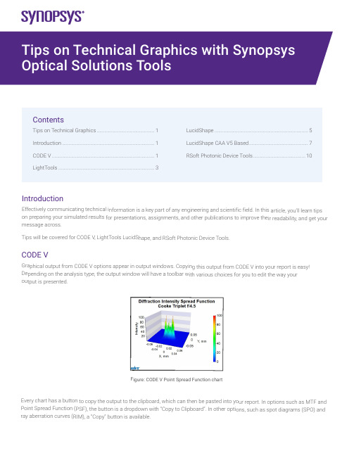
Introductio nEffectively com municating tec hnical informat ion is a key par t of any engine ering and scien tific field. In this article, you’ll le arn tips on preparing yo ur simulated re sults for presen tations, assignm ents, and other publications to improve their r eadability, and get your message acros s.Tips will be cov ered for CODE V, LightTools Lu cidShape, and R Soft Photonic D evice Tools.CODE VGraphical outp ut from CODE V options appea r in output wind ows. Copying t his output from CODE V into yo ur report is eas y! Depending on t he analysis typ e, the output w indow will have a toolbar with various choices for you to edit the way your output is presented.Figure: CODE V P oint Spread Func tion chartEvery chart has a button to cop y the output to the clipboard, w hich can then b e pasted into yo ur report. In op tions such as M TF and Point Spread F unction (PSF), t he button is a d ropdown with “Copy to Clipboa rd”. In other op tions, such as s pot diagrams (S PO) and ray aberration c urves (RIM), a “Copy” button is available.ContentsTips on Technical Graphics (1)Introduction (1)CODE V (1)LightTools ...........................................................................3LucidShape .........................................................................5LucidShape CAA V5 Based ..............................................7RSoft Photonic Device Tools .. (10)vFigure: Copying charts from CODE V’s MTF option and Spot Diagram optionAnalysis options such as MTF and PSF have buttons to increase font size and line width to aid you in making your output more legible when pasted into results. There is even an “Apply Presentation/Report Template” button to quickly prepare the chart for presentations:Figure: Controls to adjust chart font size, line width, and switch to “Apply Presentation/Report Template”Figure: MTF chart copied using the default MTF template (on left), and Presentation/Report settings (on right).Notice the text in the chart on the right is easier to read.For more extensive chart customizations, you can press the Chart Properties button to access controls for chart colors, axes scales, and more.Figure: Some options have a toolbar button to customize chart properties furtherRight click on the chart to save the property settings as a template to use later, or apply the settings to all similar charts in the window.Figure: Right clicking on a chart gives you options to apply and save templates,apply settings to all charts in the window, and revert settings back to the defaultFor charts that don’t have editable properties, such as spot diagrams and ray aberration curves, you can extract the components in Microsoft products and edit the picture:Figure: Copy of a RIM curve in Microsoft Powerpoint. Right click to edit the picture (left).Example of edited picture after adjusting font and line sizes (right)The edited picture becomes a Microsoft drawing object. These objects can then be ungrouped and moved/modified independently. LightToolsGraphical output from LightTools analysis can be accessed from the Analysis menu and choosing the metric you’d like to assess (illuminance, intensity, luminance, etc.). The main output is to present illumination metrics using the LumViewer, but there are also other types of analysis for color charts, polarization, and more. Each chart has a toolbar to help you customize how the analysis is presented.Copying charts from the LumViewer is easy! Right click on the copy icon and choose “Copy to Clipboard”. You can then paste the chart into your document.Figure: LumViewer’s “Copy to Clipboard”You can make text more readable by adjusting the font size up and down.Figure: In the LumViewer toolbar, you can adjust text font sizevFigure: Irradiance LumViewer plot copied with default settings (on left),compared to chart copied after increasing the font size to be more readible.For more extensive chart customizations, you can press the Chart Properties button to access controls for chart colors, axes scales, and more!Figure: Analysis options have a toolbar button to customize chart properties furtherRight click on the LumViewer to save the property settings as a template to use later, or apply the settings to all similar charts.Figure: Right clicking on a LumViewer chart gives you options to apply andsave templates and apply settings to all charts in the window.For luminance measurements, you can overlay forward simulation results directly on the associated geometry in the V3D window. To enable this setting, go to the View menu > Simulation Results and choose True Color or False Color.Figure: False color illuminance overlaid on lens geometry in the LightTools 3D ViewLucidShapeGraphical output from LucidShape can be customized from context menus for the specific output. After you’ve opened the results, you can customize the appearance by right clicking on the chart.Figure: Analysis from LucidShapeTo copy a chart or GeoView from LucidShape, right click in the window’s area and select “Copy Bitmap”. You can now paste the chart from the clipboard to the desired destination.Figure: To copy output from a chart or the GeoView, right click and choose “Copy Bitmap”You can use other options from the context sensitive menu as well. For example, when plotting sensor data you can switch ISO lines off for a smoother view, and select “View Properties” to open further chart customizations:Figure: For chart customization, right click and choose “View Properties”In the properties window, you can change settings such as the axes ranges, the type of chart, the scale, and more:Figure: The data properties windows lets you customize the way sensor data is presentedYou can customize the GeoView too! The context menu has choices to set the background color and edit the global axis system attributes the Stock Scene selection.• From the GeoView’s Options menu > GeoView, you can set the background color and edit stock sceneFigure: GeoView with the global axis system (on left) and without the stock scene visibleFrom the GeoView’s Options menu > Global Settings, you can increase the line widths to make wireframes clearer to see inpresentations and reports.Figure: Wireframe view with default width (on left) and increased line width (on right)The GeoView toolbar has options to change orientation and the change surface rendering mode. For instance, you can switch between shaded/wireframe modes, and even display sensor results from “Display Light Data”.Figure: GeoView with shaded geometry (on left), wireframe geometry (middle), and Display Light Data (on right) LucidShape CAA VA BasedTo take a screenshot in CATIA you can go to Tools > Image > Capture:Click the 3rd Icon “Options”:In the second tab “Pixel”, you can check “White background”, “Anti-aliasing” and switch render quality to “Highest”:Click OK, and back with these icons, click the second one “Select Mode”, and then do a left click, mode and release the left click in CATIA: a rectangle appears:By clicking the corners of the rectangle and moving them, you can resize the area which will be taken as screenshot.With the CATIA controls, you can move/rotate your design: the screenshot rectangle is not moving:Once the screenshot size is adjusted, click the first icon “Capture”: a new window is opening and you can either save the screenshot, or copy it:Also, in case you want to take a screenshot from the same viewing position, you may want to create cameras: in a product, go to Infrastructure > Photo Studio:vOn the right of the screen, click “Create camera” after you chose the view you needed:In the CATIA tree, under Applications, the camera is created. You also see a glyph in the 3D view. By double clicking the camera, you will look at your design always from the same view. With a right click, properties, you can move the camera:vRSoft Photonic Device ToolsAll RSoft Photonic Device Tools plot data through an included plotting program called WinPLOT. You can customize the plot through an editor with a comprehensive set of commands.Figure: A customized line plot (on left), and contour plot (on right) from RSoft WinPLOTCopying a plot from WinPLOT is easy, just go to the File menu > Export Graph to save to a variety of formats.Figure: Export RSoft WinPLOT plots from the File menu > Export GraphEach plot file contains a series of commands that control how the plot is displayed. Click the “View Editor” button in the toolbar to see and edit the commands. Then click the “View Plot” button to return to the plot. For example, the “/tt” command sets the “Title at the Top” of the plot. See the WinPLOT manual for command documentation.Figure: Edit WinPLOT settings from the View Editor• Learn more about using WinPLOT to create high-quality graphics for publications:–Line plots–Contour plotsVisit /optical-solutions to learn more about our optical design software tools, services, and equipment. Or contact us at ******************* so we can help you with demos, trial licenses, and product pricing.©2022 Synopsys, Inc. All rights reserved. Synopsys is a trademark of Synopsys, Inc. in the United States and other countries. A list of Synopsys trademarks isavailable at /copyright.html. All other names mentioned herein are trademarks or registered trademarks of their respective owners.03/23/22.tempfile_10000038.。
from typing import optional 的用法
from typing import optional 的用法1.引言1.1 概述"from typing import Optional"是Python中的一个重要的模块,它提供了一种新的类型注解,用于指示某个变量可以是一个特定类型的值,也可以是None。
这个模块主要用于增强代码的可读性和可维护性,同时也提供了更加严格的数据类型检查。
在Python中,变量的类型通常是动态的,这就意味着同一个变量可以在不同的上下文中被赋予不同的类型的值。
这种灵活性是Python所倡导的,但有时也容易导致潜在的错误。
当我们在编写大型复杂的代码时,往往会面临类型错误的问题。
为了解决这个问题,Python引入了类型注解的机制,允许程序员在代码中显式地指定某个变量的类型。
这样在代码中就能明确地知道变量的类型,从而增加了代码的可读性和可维护性。
"from typing import Optional"模块中的"Optional"类是一种特殊的泛型类型,它可以用来指示某个变量可以是指定类型的值,也可以是None。
它的使用方式是在类型注解中加上"Optional[]",并在方括号中指定期望的类型。
使用"Optional"类型注解的主要好处是能够明确地表达出某个变量是可选的,它可以是一个值,也可以是None。
这有助于提醒其他开发人员在处理这个变量时,要考虑到None的情况,并采取相应的处理措施,避免出现潜在的错误。
在本文的后续部分,我们将详细介绍"from typing import Optional"模块的语法和用法,以及它的优点、应用场景、限制和注意事项。
通过深入了解这个模块,我们将能够更好地利用它来编写更加可靠和健壮的Python代码。
1.2 文章结构本文将围绕着"from typing import Optional"的用法展开讨论。
富士通笔记本电脑 LIFEBOOK E5411 产品规格手册说明书
Data Sheet Fujitsu Notebook LIFEBOOK E5411Fujitsu recommends Windows 11 Pro.Data SheetFujitsu Notebook LIFEBOOK E5411Your Powerful and Modern Business DeviceThe FUJITSU Notebook LIFEBOOK E5411 is designed for office workers needing a powerful, fully-equipped notebook. Thanks to the 11th generation Intel® Core™ processor you can work efficiently wherever you are. The advanced security features like PalmSecure™ are protecting your business data against unauthorized access. Modern Standby provides you an instantly ready and always connected notebook.Modern and robust designReliable mobility, ease of use and modern good looks for everyday business demands Slim 23.9 mm entry notebook starting at 1.79 kg with a solid designEnjoy an ergonomic viewing experience with a 14.0-inch outdoor friendly anti-glare FHD display With optional touch or non-touch screen Long Lifecycle with 24 monthsReliable and secure performanceProtect your business data from unauthorized access at all times Integrated PalmSecure™ or finger print sensorInfrared Camera: Allows face recognition with Windows Hello Intel® Iris® Xe GraphicsBuilt-in Privacy Camera Shutter: Protecting your privacy SmartCard reader and TPM 2.0Best in class connectivityBe flexible and stay productive anywhere, anytimeCompact and versatile Intel® Thunderbolt™ 4 USB Type-C connector to charge your laptop, transfer files at fast speeds, connect external monitors and other peripherals Full set of ports with a full-sized HDMI, VGA and LAN connector and USB Type-C Based on the latest QuadCore Intel processor, enabling data to be processed faster Convenient serviceability and upgradeabilityEasy access to key components reduces upgrade time and costsBattery, memory, internal storage and connectivity components can be changed with ease Long-term stable platformProtect your investments and be ready for shared desk conceptsThis LIFEBOOK E5 Series provides an extraordinary guaranteed product lifecycle of 24 months.ComponentsBase unit LIFEBOOK E5411Operating systemsOperating system pre-installed Windows 11 Pro. Fujitsu recommends Windows 11 Pro for business.Windows 11 HomeWindows 10 Pro. Fujitsu recommends Windows 11 Pro for business.Operating system compatible FREE Upgrade to Windows 11**Upgrade timing may vary by device. Features and app availability may vary by region. Certain features requirespecific hardware (see aka.ms/windows11-spec).Operating system notes Windows 11 requires for first device setup:- Internet connectivity- Microsoft account for Home editions or organizational account (e.g. ADD) for Pro editionsAfter product end of life, Fujitsu continues to test and support new Windows releases for max. 5 years, depending onextension of hardware services through warranty top ups.For more details please visit our Fujitsu Service Statement under https:///IndexProdSupport.asp?lng=com&OpenTab=Processor Intel® Core™ i7-1185G7 processor (4 Cores / 8 Threads, up to 4.8 GHz)*Processor only for retail, SMB, education and governmentMemory modules 4 GB (1 module(s) 4 GB) DDR4, 3,200 MT/s, SO DIMM8 GB (1 module(s) 8 GB) DDR4, 3,200 MT/s, SO DIMM16 GB (1 module(s) 16 GB) DDR4, 3,200 MT/s, SO DIMM32 GB (1 module(s) 32 GB) DDR4, 3,200 MT/s, SO DIMMHard disk drives (internal)PCIe-SSD, 512 GB M.2 NVMe module, SEDPCIe-SSD, 256 GB M.2 NVMe module, SEDPCIe-SSD, 256 GB M.2 NVMe modulePCIe-SSD, 1 TB M.2 NVMe module, SEDHard disk notes Accessible capacity may vary, also depending on used software.Interface add on cards/components(optional)3G/4G (optional)LTE Sierra Wireless EM7421 (Cat.7) (Downlink speed up to 300 Mbit/s, Uplink speed up to 150 Mbit/s)Display35.6 cm (14.0-inch), IPS, FHD, 1,920 x 1,080 pixel, Anti-glare multi-touch, 300 cd/m² (Touch), 700:1 (Touch)35.6 cm (14.0-inch), FHD, 1,920 x 1,080 pixel, Anti-glare IPS display, 220 cd/m² (FHD), 700:1 (FHD)MultimediaCamera Built-in webcam (HD) with Status LED Built-in Infrared webcam (HD) with Status LED Camera notes720p, 1 megapixels, 1280 x 720, with Privacy Camera ShutterMicrophone dual digital array microphoneBase unitBase unit LIFEBOOK E5411General system informationChipset IntegratedSupported capacity RAM (min.) 4 GBSupported capacity RAM (max.)64 GBMemory slots 2 SO DIMM (DDR4, 3200 MHz)Memory notes Dual channel supportGeneral system informationLAN10/100/1,000 MBit/s Intel® I219LMIntegrated WLAN Intel WiFi 6 AX201 - WLAN, BT, SRD cat. 1BIOS version UEFI Specification 2.7BIOS features InsydeH2O BIOSAudio type On boardAudio codec Realtek ALC255Audio features2x built-in speakers (stereo)MIL-STD tested Yes, selected MIL-STD-810H tests passed.MIL-STD-810H test results are not a guarantee of future performance under identified test conditions.Accidental damage is not covered under standard international limited warranty.DisplayDisplay notes FHD - Viewing angle: Left/Right 80°, Top 80°, Bottom 80°; Color Gamut: 45% NTSC, response time 25 ms* HD Display option available in LIFEBOOK E5411/HD baseunit *GraphicsBase unit LIFEBOOK E5411TFT resolution (HDMI)Up to 4,096 x 2,160 pixel (30 Hz)TFT resolution (VGA)up to 1,920 x 1,200Graphics brand name Intel® UHD Graphics (with Single channel memory), Intel® Iris® Xe Graphics (with Dual channel memory) Graphics features 3 Display SupportDirectX® 12OpenGL® 4.5Graphics notes Shared memory depending on main memory size and operating systemInterfaces (Base unit specific)DC-in1Audio: line-in / line-out1Internal microphones2x digital array microphones (optional)USB 3.2 Gen1 (5 Gbps) total2x Type-A (1 with Anytime USB charge functionality)USB 4.0 Gen3 (20 Gbps) total1x Type-C Intel® Thunderbolt™ 4 (40Gbps), Power Delivery (15W), DP outVGA1HDMI 1 supports resolutions as specified in HDMI 1.4bEthernet (RJ-45)1Memory card slots 1 SD 3.0 StandardSD/microSD cardSDHC/microSDHC cardSDXC/microSDXC cardSpeed Class: up to UHS-ISmartCard slot 1 (optional)SIM card slot 1 (Nano-SIM, only for models with integrated 4G/LTE module)Docking connector for Port Replicator1Kensington Lock support1Port Replicator interfaces (optional)Thunderbolt™ 4 PR Model: NPR46 (mech. PR)USB Type-C PRDC-in 1 (20V/170W required) 1 (19V/90W required) 1 (19V/90W required)Power on switch111Audio: headphone---1---Audio: microphone---1---Audio: comments 1 Combo jack for headset usage--- 1 Combo jack for headset usage---USB 3.2 Gen1 (5 Gbps) total---4x Type-A2x Type-CDisplayPort2x V1.4++ 2 (up to 2x 3840x2160 60Hz)1x V1.2VGA--- 1 (up to 1920x1200 60Hz)1DVI--- 1 (up to 1920x1200 60Hz)---HDMI text V 2.0b---1Port Replicator interfaces (optional)Interface Notes2x Type-A - 5V/0.9A, 4.5W1x Type-A - 5V/2.4A, 12W2x Type-C - 5V, 1.5A/4.5W chargingport1x Type-C - TBT4 up to 60 W (PD v2.0-1.1), 5-20V/3.0A upstream (PC), IntelAMT support (vPRO)1x Type-C - TBT4 up to 15 W (PDv2.0-1.1), 5V/3.0A downstream, poweroutput to client ---3x Type-A - 5V/0.9A, 4.5W1x Type-C - 15W1x Type-C - Up to 60 W (PD v2.0-1.1)power output to client or 4.5W inputKensington Lock support1 1 (Portrep only, Portrep option withkey lock to secure Portrep & System)no Ethernet (RJ-45) 1 (10/100/1000 Mbit/s, 2,5 Gbps)---1Notes Number of simultaneous useddisplays and its possible resolutionsand frequencies depend on mobilesystem and display interface type.Please consult always also the manualof the connected client.1 RJ45 (10/100/1000)Number of simultaneous useddisplays and its possible resolutionsand frequencies depend on mobilesystem and display interface type.Please consult always also the manualof the connected client.Keyboard and pointing devicesKeyboard w/o touchstick (spill-resistant), Keyboard w/ touchstick, Backlit keyboard w/o touchstickNumber of keyboard keys: 85, Keyboard pitch: 18.4 mm, Keyboard stroke: 1.7 mmMulti gesture touchpad with two mouse buttonsWireless technologiesAntennas 2 Dual band WLAN antennas, 2 LTE antennas optionalBluetooth v5.1Integrated WLAN Intel WiFi 6 AX201 - WLAN, BT, SRD cat. 1WLAN encryption WPA/WPA2/WPA3 (Wi-Fi Protected Access)WLAN notes Import and usage according to country-specific regulations.LTE/UMTS/GPS notes OptionalIntegrated WWAN LTE Sierra Wireless EM7421 (cat.7) - UMTS,LTEGPS Embedded in 4G module if configured with WWANPower supplyAC Adapter20 V / 65 W (3.25 A), 100 V - 240 V, 50 Hz - 60 Hz, 3-pin (grounded) Type-C AC-Adapter standardAC Adapter19 V / 90 W (4.74 A), 100 V - 240 V, 50 Hz - 60 Hz, 3-pin (grounded) DC-in AC-Adapter (for PR)AC Adapter19 V / 65 W (3.42 A), 100 V - 240 V, 50 Hz - 60 Hz, 3-pin (grounded) DC-in AC-AdapterAC Adapter20 V / 65 W (3.25 A), 100 V - 240 V, 50 Hz - 60 Hz, 3-pin (grounded) Type-C AC-Adapter slim&lightNotes65W AC Adapter for usage with system/ 90W AC Adapter for usage with Port Replicator1st battery Lithium polymer battery 4-cell, 50 Wh, 3,490 mAhBattery features Quick Charge: 80% in 1hRuntime 1st battery9 h 10 minBattery notes Battery runtime information is based on worldwide acknowledged BAPCo® MobileMark® 2018. Refer to www.bapco.com for additional details.The BAPCo® MobileMark® Benchmark provides results that enable direct product comparisons betweenmanufacturers. It does not guarantee any specific battery runtime which actually can be lower and may varydepending on product model, configuration, application and power management settings. The battery capacitydecreases slightly with every re-charge and over its lifetime.Noise emissionNoise emission Please refer to the Eco DeclarationDimensions / Weight / EnvironmentalDimensions (W x D x H)333.6 x 234 x 23.9 mm13.13 x 9.21 x 0.94 inchWeight 1.79 kgWeight (lbs) 3.94 lbsDimensions / Weight / EnvironmentalWeight notes Weight may vary depending on actual configurationOperating ambient temperature 5 - 35 °C (41 - 95 °F)Operating relative humidity20 - 80 %ComplianceProduct LIFEBOOK E5411Model5E14A2Germany GS (Full HD Display only)Europe CECBUSA/Canada FCC (depending on configuration) (planned)Global RoHS (Restriction of hazardous substances)WEEE (Waste electrical and electronic equipment)Microsoft Operating Systems (HCT / HCL entry / WHQL)TCO Certified 8.0 (depending on configuration)EPEAT® Silver (dedicated regions), depending on configurationENERGY STAR® 8.0MIL-STD-810H testedIndia BISRussia EACChina CCC (depending on configuration)Compliance link https:///sites/certificatesAdditional SoftwareAdditional software (preinstalled)Fujitsu Plugfree Network (network management utility)Fujitsu Anytime USB Charge UtilityFujitsu Battery UtilityFujitsu Function ManagerFujitsu DeskUpdate (driver and utility tool)Additional software (optional)Recovery DVD for Windows®Drivers & Utilities DVD (DUDVD)Microsoft® Office Professional 2019Microsoft® Office Home and Business 2019(A Microsoft Account is required to activate each copy of these products. For purchase and activation only in theregion in which it was acquired.)Additional software (notes)Use of accompanying and/or additional Software is subject to proactive acceptance of the respective LicenseAgreements /EULAs/ Subscription and support terms of the Software manufacturer as applicable for the relevantSoftware whether preinstalled or optional. The software may only be available bundled with a software supportsubscription which – depending on the Software - may be subject to separate remuneration.ManageabilityManageability technology DeskUpdate Driver managementPXE 2.1 Boot codeWake up from S5 (off mode)WoL (Wake on LAN)Intel® vPro™ technologyManageability software DeskView ClientDeskView Instant BIOS ManagementDeskView components Inventory ManagementBIOS ManagementDriver ManagementSecurity ManagementAlarm ManagementSupported standards WMI (Windows Management Instrumentation)PXE (Preboot Execution Environment)DMI (Desktop Management Interface)SMBIOS (System Management BIOS)CIM (Common Information Model)BootP (made4you)Manageability link https:///global/products/computing/pc/manageability/SecuritySystem and BIOS Security EraseDiskTrusted Platform Module (TPM 2.0)User SecurityEmbedded PalmSecure™ sensor (optional)Embedded fingerprint sensor (optional)Access protection via internal SmartCard reader (optional)Hard disk passwordUser and supervisor BIOS passwordSecurity NotesThe properties of the product provide a baseline for product security and therefore end-customer IT security. However, these properties are not sufficient on their own to protect the product from all existing threats, such as intrusion attempts, data exfiltration and other forms of cyberattacks. To customize security settings, please use the configuration options as available for the respective product. During operation, the IT security of this product is within the responsibility of the respective administrator/end-user of the product. Please note, that Fujitsu as a manufacturer does not make any policy prescriptions or advocacy statements regarding IT security best practices and/or general product operation.Warranty Warranty period 1 year (for countries in EMEIA)Warranty typeBring-in Service / Collect & Return Service (depending on country)Warranty Terms & Conditions /warrantyDigital bug fixesSubject to availability and following their generic release for the product, bug fixes and function-preserving patches for product-related software (firmware) can be downloaded from the technical support at: https:/// free of charge by entering the respective product serial number. For application software supplied together with the product, please directly refer to the support websites of the respective software manufacturer.Product Support - the perfect extension Recommended Service 9x5, Onsite Response Time: Next Business DaySpare Parts availability at least 5 years after shipment, for details see https:///Service Weblink/emeia/products/product-support-services/Recommended AccessoriesPort Replicator for LIFEBOOK U7 and E5 family with key lock(2020)Flexibility, expandability, desktop replacement, investment protection – to name just a few benefits of Fujitsu’s docking options.Order Code: S26391-F1607-L219USB Type-C Port Replicator 2Connect to your peripherals. Adapt to the task on demand. The universal USB Type-C interface supports you to get your peripheral devicesconnected easily. Multiply your USB ports to connect your peripherals as well as your external display via HDMI, DisplayPort or VGA.You also can charge your external USB devices without the need of any additional charger.Order Code:S26391-F3327-L100Battery 4 cell 50 WhThe 4 cell 50 Wh battery requires a voltage of 14.4 V and has a capacity of 3490 mAh. The weight of the battery is 300 gms and the recharge time of the cell is 60 minutes for a 80% charge and 150 minutes for a complete 100% charge.Order Code:S26391-F1616-L100Prestige Backpack 17 (2021)The Fujitsu Prestige Backpack 17 (2021) protects notebooks with up to 17-inch displays. It contains three large compartments, an elastic mesh side pocket and a front bay. The padded back compartment provides protection for your notebook, while the other sections store power adaptors and office supplies. Padded shoulder straps and back cushions provide comfort on the move.Order Code:S26391-F1120-L135Wireless Mouse WI860 BTCThe Wireless Mouse WI860 BTC can be paired with up to 3 different clients, 2x Bluetooth and 1x wireless USB Type-C dongle.With the blue optical sensor, it works on nearly all surfaces with an 3-step adjustable DPI selector (800/1600/2400).The mouse charges wirelessly through Qi or by USB Type-C cable.A utility button on the side is programmable. The default functions are optimized for Teams calls.Order Code:S26381-K474-L100ContactFujitsu Technology Solutions GmbH Website: 2023-05-02 EM-ENworldwide project for reducing burdens on the environment.Using our global know-how, we aim to contribute to the creation of a sustainable environment for future generations through IT.Please find further information at http://www./global/about/environmenttechnical specification with the maximum selection of components for the named system and not the detailed scope ofdelivery. The scope of delivery is defined by the selection of components at the time of ordering.Technical data is subject to modification and delivery subject to availability. Any liability that the data and illustrations are complete, actual or correct is excluded. Designations may be trademarks and/or copyrights of the respective owner, the use of which by third parties for their own purposes may infringe the rights of such owner.The overall product has been designed and manufactured for general office use, regular personal use and ordinary industrial use.More informationAll rights reserved, including intellectual property rights. Designations may be trademarks and/or copyrights of therespective owner, the use of which by third parties for their own purposes may infringe the rights of such owner. For further information see https:///global/about/resources/terms/ Copyright 2023 Fujitsu Technology Solutions GmbH。
车辆诊断协议SAEJ2534-2-OptionalPass-ThruFeatures
车辆诊断协议SAEJ2534-2-OptionalPass-ThruFeatures VEHICLERECOMMENDED SAE Technical Standards Board Rules provide that: “This report is published by SAE to advance the state of technical and engineering sciences. The use of this report isentirely voluntary, and its applicability and suitability for any particular use, including any patent infringement arising therefrom, is the sole responsibility of the user.”SAE reviews each technical report at least every five years at which time it may be reaffirmed, revised, or cancelled. SAE invites your written comments and suggestions.Copyright ? 2006 SAE InternationalAll rights reserved. No part of this publication may be reproduced, stored in a retrieval system or transmitted, in any form or by any means, electronic, mechanical, photocopying, recording, or otherwise, without the prior written permission of SAE.6.Access to Additional Channels (10)7.Accessing Multiple SAE J2534 Devices (10)8.Mixed Format Frames on a CAN Network (10)8.1Scope of the Mixed Format Frames on a CAN Network Optional Feature (10)8.2Win32 Application Programming Interface (11)8.2.1API Functions – Overview (11)8.2.2API Functions – Detailed Information (14)8.2.2.1 PassThruReadMsgs (14)8.2.2.2PassThruWriteMsgs (14)8.2.2.3PassThruStartPeriodicMsg (15)8.2.2.4PassThruStartMsgFilter (15)8.2.3IOCTL Section (15)8.2.3.1GET_CONFIG (16)8.2.3.2SET_CONFIG (16)8.3Message Structure (17)8.3.1Elements (17)9.Single Wire CAN (17)9.1Scope of the Single Wire CAN Optional Feature (17)9.2Pass-Thru System Requirements (17)9.2.1Pin Usage (17)9.3Win32 Application Programming Interface (17)9.3.1API Functions – Overview (17)9.3.2API Functions – Detailed Information (19)9.3.2.1PassThruConnect (19)9.3.2.2ProtocolID Values (19)9.3.2.3PassThruReadMsgs (20)9.3.3IOCTL Section (20)9.3.3.1GET_CONFIG (20)9.3.3.2SET_CONFIG (21)9.3.3.3SW_CAN_HS (21)9.3.3.4SW_CAN_NS (22)9.4Message Structure (22)9.4.1Elements (22)9.4.1.1RxStatus (23)9.4.1.2TxFlags (23)10.Analog Inputs (24)10.1Scope of the Analog Inputs Optional Feature (24)10.2Pass-Thru System Requirements (24)10.2.1Analog Inputs (24)10.2.2Simultaneous Communication on Multiple Protocols (24) 10.3Win32 Application Programming Interface (24)10.3.1API Functions – Overview (24)10.3.2API Functions – Detailed Information (25)10.3.2.1PassThruConnect (25)10.3.2.2ProtocolID Values (25)10.3.2.3PassThruReadMsgs (25)10.3.2.4PassThruWriteMsgs (25)10.3.2.5PassThruStartPeriodicMsg (25)10.3.2.6PassThruStopPeriodicMsg (26)10.3.2.7PassThruStartMsgFilter (26)10.3.2.8PassThruStopMsgFilter (26)10.3.3IOCTL Section (26)10.3.3.1GET_CONFIG (26)10.3.3.2SET_CONFIG (26)10.3.3.2.1ACTIVE_CHANNELS (27)10.3.3.2.2SAMPLE_RATE (28)10.3.3.2.3SAMPLES_PER_READING (28)10.3.3.2.4READINGS_PER_MSG (28)10.3.3.2.5AVERAGING_METHOD (29)10.3.3.2.5.1SIMPLE_AVERAGE (29)10.3.3.2.5.2MAX_LIMIT_AVERAGE (29)10.3.3.2.5.3MIN_LIMIT_AVERAGE (29)10.3.3.2.5.4MEDIAN_AVERAGE (30)10.3.3.2.5.5Vendor-Specific Averaging Methods (30)10.3.3.2.6SAMPLE_RESOLUTION (30)10.3.3.2.7INPUT_RANGE_LOW (30)10.3.3.2.8INPUT_RANGE_HIGH (30)10.3.3.3FIVE_BAUD_INIT (30)10.3.3.4FAST_INIT (30)10.3.3.5CLEAR_TX_BUFFER (30)10.3.3.6CLEAR_RX_BUFFER (30)10.3.3.7CLEAR_PERIODIC_MSGS (30)10.3.3.8CLEAR_MSG_FILTERS (31)10.3.3.9CLEAR_FUNCT_MSG_LOOKUP_TABLE (31)10.3.3.10ADD_TO_FUNCT_MSG_LOOKUP_TABLE (31)10.3.3.11DELETE_FROM_FUNCT_MSG_LOOKUP_TABLE (31) 10.4Message Structure (31)10.4.1Examples: (32)10.4.2Message Flag and Status Definitions (33)11.GM UART (SAE J2740) (33)11.1Scope of the GM UART Optional Feature (33)11.2Pass-Thru System Requirements (33)11.2.1Pin Usage (33)11.3Win32 Application Programming Interface (34)11.3.1API Functions – Overview (34)11.3.2API Functions – Detailed Information (35)11.3.2.1PassThruConnect (35)11.3.2.1.1ProtocolID Values (GM UART) (35)11.3.3IOCTL Section (36)11.3.3.1SET_POLL_RESPONSE (36)11.3.3.2BECOME_MASTER (37)11.4Message Structure (40)11.4.1Elements (40)11.4.2Message Data Formats (40)11.5DLL Installation and Registration (40)6.Access to Additional ChannelsThis section defines an optional mechanism available to initiate and use multiple channels of the same protocol, if vendor hardware provides the support. The channels addressed this way may not be tied to pins on the SAE J1962 connector. What channel appears at what pins on the interface device will depend on the vendor configuration.For example a particular vendor’s hardware may support four channels of dual-wire high-speed CAN. These additional channels will be available as separate ProtocolIDs defined by SAE J2534-2. This document will allocate 128 predefined ProtocolIDs for each protocol to target a possible maximum of 128 channels of each protocol. The ProtocolIDs will follow the following format:CAN_CH1C AN_CH2…………..C AN_CH128This scheme of providing additional ProtocolIDs will apply to both SAE J2534-1 and SAE J2534-2 defined protocols. A complete list of ProtocolIDs for multiple channel access can be found in the ‘SAE J2534-2 Resources’ section.7.Accessing Multiple SAE J2534 DevicesSAE J2534-2 allows the use of multiple devices from the same PC. The connection is established by passing the device identification in the PassThruOpen pName parameter. This function will expect this parameter to be a NULL terminated string, typecast as a void pointer. The content of the string is currently vendor specific.It is acceptable to pass a NULL parameter as defined in SAE J2534-1. In this case, the vendor determined default device will be selected.8.Mixed Format Frames on a CAN Network8.1Scope of the Mixed Format Frames on a CAN Network Optional FeatureThis section details the extensions to SAE J2534-1 that will allow the simultaneous reception and transmission of ISO 15765 messages and unformatted CAN frames on an ISO 15765 channel. The ProtocolID (in the PASSTHRU_MSG structure) will be used to identify the format of the associated message. This section details only the changes from SAE J2534-1. Items not specifically detailed in this document are assumed not to have changed.8.2.2.3PassThruStartPeriodicMsgThere is no change to this function. H owever, only ISO 15765 channels will allow the IOCTL configuration parameter CAN_MIXED_FORMAT to be either CAN_MIXED_FORMAT_ON or CAN_MIXED_FORMAT_ALL_FRAMES. In these cases, the ProtocolID in the PASSTHRU_MSG structure shall reflect either an unformatted CAN frame (e.g., CAN,SW_CAN_PS, etc.) or an ISO 15765 message (e.g., ISO15765, SW_ISO15765_PS, etc.). Consult the appropriate SAE J2534 document for the requirements, restrictions, and error conditions for the specific protocol. This function will return a value of ERR_MSG_PROTOCOL_ID if the IOCTL configuration parameter CAN_MIXED_FORMAT is set toCAN_MIXED_FORMAT_OFF and the ProtocolID reflects an unformatted CAN frame.Additionally, each time the IOCTL configuration parameter CAN_MIXED_FORMAT is set, periodic messages with ProtocolID of CAN shall be deleted.The SAE J2534 device will not protect the user from writing a CAN message that may be interpreted as a valid ISO 15765 frame. The consequences of this action are undefined and may disrupt ISO 15765 communications taking place on the network.8.2.2.4PassThruStartMsgFilterEach ISO 15765 channel shall support a minimum of 64 FLOW_CONTROL_FILTER s as well as 10PASS_FILTERs/BLOCK_FILTERs.This function shall be used to identify ISO 15765 messages as well as unformatted CAN frames. A received message that matches a FLOW_CONTROL_FILTER shall be processed as an ISO 15765 message and shall have the appropriate ProtocolID in the PASSTHRU_MSG structure before it is added to the receive queue. Additionally, based upon the setting of CAN_MIXED_FORMAT, the CAN frames may also be subject to the PASS_FILTER s and BLOCK_FILTER s, where the ProtocolID in the PASSTHRU_MSG structure shall be set to reflect an unformatted CAN frame before it is added to the receive queue.Only ISO 15765 channels will allow the IOCTL configuration parameter CAN_MIXED_FORMAT to be set to eitherCAN_MIXED_FORMAT_ON or CAN_MIXED_FORMAT_ALL_FRAMES. In these cases, the ProtocolID in the PASSTHRU_MSG structure must reflect an unformatted CAN frame (e.g., CAN, SW_CAN_PS, etc.) for a PASS_FILTER or a BLOCK_FILTER and an ISO 15765 message (e.g., ISO15765, SW_ISO15765_PS, etc.) for a FLOW_CONTROL_FILTER. Consult the appropriate SAE J2534 document for the requirements, restrictions, and error conditions for the specific protocol and filter type. This function will return a value of ERR_MSG_PROTOCOL_ID if the ProtocolID is not appropriate for the type of filter being started.Additionally, each time the IOCTL configuration parameter CAN_MIXED_FORMAT is set all PASS_FILTERs andBLOCK_FILTERs shall be deleted.8.2.3IOCTL S ECTIONIf this feature is not supported on the current ISO 15765 channel, the call to get or set the IOCTL configuration parameter CAN_MIXED_FORMAT shall return the value ERR_INVALID_IOCTL_VALUE.8.3Message Structure8.3.1E LEMENTSThere is no change to any of the elements, but it should be noted that the ProtocolID in the PASSTHRU_MSG structure shall identify the message type (e.g., ISO15765, CAN, SW_ISO15765_PS, SW_CAN_PS, etc.). Consult the appropriate SAEJ2534 document for the requirements, restrictions, and error conditions for the specific protocol.9.Single Wire CAN9.1Scope of the Single Wire CAN Optional FeatureInformation contained in this section will define extensions to a compliant SAE J2534-1 interface to support Single WireCAN.9.2Pass-Thru System Requirements9.2.1P IN U SAGEGeneral Motors Corporation use of Single Wire CAN is connected to pin 1 of the SAE J1962 connector. Note that when PassThruConnect is called, the physical layer remains disconnected until a call to PassThruIoctl, SET_CONFIG,J1962_PINS is made.9.3Win32 Application Programming Interface9.3.1API F UNCTIONS –O VERVIEWInformation contained in this document is intended to define the API resources required to incorporate an optional protocol channel. This channel, identified as Single-Wire CAN (SWCAN), will require hardware and software API support to fully implement this feature.The details on the physical implementation of SWCAN are defined in GMW3089, titled “GMLAN Single Wire CAN Physical and Data Link Layers Specification.”This document outlines the requirements for providing an interface channel supporting this protocol.At a high level a new ProtocolID has been defined to indicate the use of the Single Wire CAN physical layer. Additionally, Flags required to support high voltage wake up and high / normal speed are defined as required. The device is required to support high voltage wakeup and time critical data rate changes defined in SWCAN specification. This document details the API resources required to enable use of the SAE J2534 API as applied to SWCAN.If this feature is not supported an error code, ERR_INVALID_PROTOCOL_ID, will be returned by the call PassThruConnect. The calling application will be required to notify the user that this optional feature may not be supported by the interface. ExampleThe IOCTL and Configuration settings related to SWCAN speed change and load resistor control are designed for use when the SAE J2534-2 hardware interface is used in either of two modes:1. As a hardware interface for a flash programming application (such as DPS).2. As a hardware interface for any other application that could be used to monitor traffic during a flashprogramming event performed by another test tool on the bus.GMW3110 requires a maximum transition time of 30 msec to switch between bus speeds. Depending on the individual SAE J2534-2 hardware interface and its associated PC communications interface and application processing speed, the 30 msec transition time may or may not be met using speed transition logic that is embedded in the PC application. The IOCTL and Configuration settings allow for this speed change logic to be controlled by either the application or the SAE J2534-2 hardware interface itself.Since not all application / SAE J2534-2 interface combinations can control speed transition timing within the GMW3110 specification, a method is required to allow the SAE J2534-2 hardware interface to automatically switch speeds while performing a flash programming operation. The following example illustrates this sequence:Assume all settings are in the Default mode.1. The application sets the configuration of the SW_CAN_RES_SWITCH parameter to 2 –AUTO_RESISTOR.2. The application sets the configuration of SW_CAN_SPEEDC H ANGE_ENABLE to 1 –ENABLE_SPDCHANGE.3. The application sends the correct GMW 3110 H S programming message sequence ($A5 $02,$A5 $03).4. The SAE J2534-2 hardware interface monitors the ($A5 $02, $A5 $03) sequence and automaticallyswitches in the load resistor, changes the SWCAN transceiver mode, and reconfigures the CAN controller. Note that this must be accomplished within 30 msec of the $A5 $03 frame. A SW_CAN_HS_RX indication will be generated upon completion of this transition.5. Upon completion of the flash programming event, the application transmits the return to normal modecommand (mode $20). A SW_CAN_NS_RX indication will be generated upon completion of this transition.6. The SAE J2534-2 hardware interface responds to the return to normal mode command, whichreconfigures the CAN controller, changes the transceiver mode, and disconnects the load resistor.Note that this must be accomplished within 30 msec of the transmission of the return to normal mode frame.There are also times when the SAE J2534-2 hardware interface could be used with a separate application to monitor a flash-programming event being performed by another test tool. In this case, the SAE J2534-2 hardware interface would need to be able to perform speed transitions within the GMW3110 specified limit. An SAE J2534-2 hardware interface used in this manner should not connect its load resistor, as this functionality should already be contained in the test tool performing the flash-programming event.。
马兰士 SR8200说明书
R Model SR8200 User GuideAV Surround ReceiverThe lightning flash with arrowhead symbolwithin an equilateral triangle is intended toalert the user to the presence of uninsulated“dangerous voltage” within the product’senclosure that may be of sufficient magnitudeto constitute a risk of electric shock to persons.The exclamation point within an equilateraltriangle is intended to alert the user to thepresence of important operating andmaintenance (servicing) instructions in theliterature accompanying the product.WARNINGTO REDUCE THE RISK OF FIRE OR ELECTRIC SHOCK,DO NOT EXPOSE THIS PRODUCT TO RAIN OR MOISTURE.CAUTION: TO PREVENT ELECTRIC SHOCK, MATCH WIDEBLADE OF PLUG TO WIDE SLOT, FULLY INSERT.ATTENTION: POUR ÉVITER LES CHOC ÉLECTRIQUES,INTRODUIRE LA LAME LA PLUS LARGE DE LA FICHE DANS LABORNE CORRESPONDANTE DE LA PRISE ET POUSSERJUSQU’AU FOND.NOTE TO CATV SYSTEM INSTALLER:This reminder is provided to call the CATV (Cable-TV) system installer’s attention to Section 820-40 of the NEC which provides guidelines for proper grounding and, in particular, specifies that the cable ground shall be connected to the grounding system of the building, as close to the point of cable entry as practical.NOTE:This equipment has been tested and found to comply withthe limits for a Class B digital device, pursuant to Part 15of the FCC Rules. These limits are designed to providereasonable protection against harmful interference in aresidential installation. This equipment generates, usesand can radiate radio frequency energy and, if notinstalled and used in accordance with the instructions,may cause harmful interference to radio communica-tions. However, there is no guarantee that interferencewill not occur in a particular installation. If this equipmentdoes cause harmful interference to radio or televisionreception, which can be determined by tuning theequipment off and on, the user is encouraged to try tocorrect the interference by one or more of the followingmeasures:-Reorient or relocate the receiving antenna.-Increase the separation between the equipment and receiver.-Connect the equipment into an outlet on a circuit differentfrom that to which the receiver is connected.-Consult the dealer or an experienced radio/TV technician forhelp.NOTE:Changes or modifications not expressly approved by theparty responsible for compliance could void the user’sauthority to operate the equipment.IMPORTANT SAFETY INSTRUCTIONSREAD BEFORE OPERATING EQUIPMENTThis product was designed and manufactured to meet strict quality and safety standards. There are, however, some installation and operation precautions which you should be particularly aware of.1.Read Instructions – All the safety and operating instructionsshould be read before the product is operated.2.Retain Instructions – The safety and operating instructions shouldbe retained for future reference.3.Heed Warnings – All warnings on the product and in the operatinginstructions should be adhered to.4.Follow Instructions – All operating and use instructions should befollowed.5.Cleaning – Unplug this product from the wall outlet beforecleaning. Do not use liquid cleaners or aerosol cleaners. Use a damp cloth for cleaning.6.Attachments – Do not use attachments not recommended by theproduct manufacturer as they may cause hazards.7.Water and Moisture – Do not use this product near water-forexample, near a bath tub, wash bowl, kitchen sink, or laundry tub, in a wet basement, or near a swimming pool, and the like.8.Accessories – Do not place this product on an unstable cart,stand, tripod, bracket, or table. The product may fall, causing serious injury to a child or adult, and serious damage to the product. Use only with a cart, stand, tripod, bracket, or table recommended by the manufacturer, or sold with the product. Any mounting of the product should follow the manufacturer’s instructions, and should use a mounting accessory recommended by the manufacturer.9. A product and cart combination should be moved with care. Quickstops, excessive force, and uneven surfaces may cause theproduct and cart combination to overturn.10.Ventilation – Slots and openings in the cabinet are provided forventilation and to ensure reliable operation of the product and to protect it from overheating, and these openings must not be blocked or covered. The openings should never be blocked by placing the product on a bed, sofa, rug, or other similar surface.This product should not be placed in a built-in installation such asa bookcase or rack unless proper ventilation is provided or themanufacturer’s instructions have been adhered to.11.Power Sources – This product should be operated only from thetype of power source indicated on the marking label. If you are not sure of the type of power supply to your home, consult your product dealer or local power company. For products intended to operate from battery power, or other sources, refer to the operating instructions.12.Grounding or Polarization – This product may be equipped with apolarized alternating-current line plug (a plug having one blade wider than the other). This plug will fit into the power outlet only one way. This is a safety feature. If you are unable to insert the plug fully into the outlet, try reversing the plug. If the plug should still fail to fit, contact your electrician to replace your obsolete outlet. Do not defeat the safety purpose of the polarized plug.AC POLARIZED PLUG13.Power-Cord Protection – Power-supply cords should be routed sothat they are not likely to be walked on or pinched by items placed upon or against them, paying particular attention to cords at plugs, convenience receptacles, and the point where they exit from the product.14.Protective Attachment Plug – The product is equipped with anattachment plug having overload protection. This is a safety feature. See Instruction Manual for replacement or resetting of protective device. If replacement of the plug is required, be sure the service technician has used a replacement plug specified by the manufacturer that has the same overload protection as the original plug.15.Outdoor Antenna Grounding – If an outside antenna or cablesystem is connected to the product, be sure the antenna or cable system is grounded so as to provide some protection against voltage surges and built-up static charges. Article 810 of the National Electrical Code, ANSI/NFPA 70, provides information with regard to proper grounding of the mast and supporting structure, grounding of the lead-in wire to an antenna discharge unit, size of grounding conductors, location of antenna-discharge unit, connection to grounding electrodes, and requirements for the grounding electrode. See Figure 1.16.Lightning – For added protection for this product during a lightningstorm, or when it is left unattended and unused for long periods of time, unplug it from the wall outlet and disconnect the antenna or cable system. This will prevent damage to the product due to lightning and power-line surges.17.Power Lines – An outside antenna system should not be locatedin the vicinity of overhead power lines or other electric light or power circuits, or where it can fall into such power lines or circuits.When installing an outside antenna system, extreme care should be taken to keep from touching such power lines or circuits as contact with them might be fatal.18.Overloading – Do not overload wall outlets, extension cords, orintegral convenience receptacles as this can result in a risk of fire or electric shock.19.Object and Liquid Entry – Never push objects of any kind into thisproduct through openings as they may touch dangerous voltage points or short-out parts that could result in a fire or electric shock.Never spill liquid of any kind on the product.iii20.Servicing – Do not attempt to service this product yourself as opening or removing covers may expose you to dangerous voltage or other hazards. Refer all servicing to qualified service personnel.21.Damage Requiring Service – Unplug this product from the wall outlet and refer servicing to qualified service personnel under the following conditions:a.When the power-supply cord or plug is damaged.b.If liquid has been spilled, or objects have fallen into the product.c.If the product has been exposed to rain or water.d.If the product does not operate normally by following the operating instructions. Adjust only those controls that are covered by the operating instructions as an improper adjustment of other controls may result in damage and will often require extensive work by a qualified technician to restore the product to its normal operation.e.If the product has been dropped or damaged in any way, and f.When the product exhibits a distinct change in performance – this indicates a need for service.22.Replacement Parts – When replacement parts are required, be sure the service technician has used replacement parts specified by the manufacturer or have the same characteristics as the original part. Unauthorized substitutions may result in fire, electric shock, or other hazards.23.Safety Check – Upon completion of any service or repairs to this product, ask the service technician to perform safety checks to determine that the product is in proper operating condition.24.Wall or Ceiling Mounting – The product should be mounted to a wall or ceiling only as recommended by the manufacturer.25.Heat – The product should be situated away from heat sources such as radiators, heat registers, stoves, or other products (including amplifiers) that produce heat.FIGURE 1EXAMPLE OF ANTENNA GROUNDING AS PER NATIONAL ELECTRICAL CODE, ANSI/NFPA 70This Class B digital apparatus complies with Canadian ICES-003.Cet appareil numérique de la Classe B est conforme à la norme NMB-003 du Canada.NEC - NATIONAL ELECTRICAL CODE(NEC ART 250, PART H)FEATURES (2)AMPLIFIER FEATURES (2)AUDIO/VIDEO FEATURES (2)FLEXBILITY FEATURES (2)OTHER FEATURES (2)DESCRIPTION (3)FRONT PANEL (5)FL DISPLAY (7)REAR PANEL (9)REMOTE CONTROL UNIT RC3200A (11)LOADING BATTERIES (11)ACTIVATING THE RC3200A (11)OPERATING DEVICES (12)REMOTE-CONTROLLABLE RANGE (12)OPERATING AMP & TUNER (13)SHOW THE STATUS OF SR8200 ON THE LCD OF RC3200A (15)WORKING WITH MODES (16)ADJUSTING THE SETTINGS (16)LEARNING COMMANDS (18)RECORDING MACROS (18)RC3200 EDIT (20)IMPORTANT NOTICES (21)CLEANING RC3200A (21)HOW TO RESET THE RC3200A (21)CONNECTING (22)CONNECTING THE AUDIO COMPONENTS (22)CONNECTING THE VIDEO COMPONENTS (22)CONNECTING THE VIDEO COMPONENTS WITH S-VIDEO / COMPONENT (23)CONNECTING THE MONITOR AND VIDEO CAMERA (23)CONNECTING THE DIGITAL / 7.1CH INPUT (24)CONNECTING THE SPEAKERS (24)CONNECTING THE SPEAKERS WITH EXTERNAL AMPLIFIER (25)CONNECTING THE ANTENNA AND POWER CORD (25)CONNECTING THE REMOTE CONTROL BUS (RC-5) (26)CONNECTING FOR THE MULTI ROOM (26)SETUP (27)ON SCREEN DISPLAY MENU SYSTEM (27)INPUT SETUP (ASSIGNABLE DIGITAL INPUT) (28)SPEAKER SETUP (28)PREFERENCE (30)SURROUND (31)PL2 (PRO LOGIC II) MUSIC PARAMETER (31)MULTI ROOM (32)7.1 CH INPUT LEVEL (32)DC TRIGGER SETUP.................................................................................32BASIC OPERATION (PLAY BACK) (33)SELECTING AN INPUT SOURCE (33)SELECTING THE SURROUND MODE (33)ADJUSTING THE MAIN VOLUME (33)ADJUSTING THE TONE(BASS & TREBLE) CONTROL (33)TEMPORARILY TURNING OFF THE SOUND (34)USING THE SLEEP TIMER (34)NIGHT MODE (34)DIALOGUE NORMALIZATION MESSAGE (34)SURROUND MODE (35)OTHER FUNCTION (39)TV AUTO ON/OFF FUNCTION (39)ATTENUATION TO ANALOG INPUT SIGNAL (39)LISTENING OVER HEADPHONES (39)VIDEO ON/OFF (39)DISPLAY MODE (39)SELECTING ANALOG AUDIO INPUT OR DIGITAL AUDIO INPUT (39)RECORDING AN ANALOG SOURCE (40)RECORDING A DIGITAL SOURCE (40)7.1 CH INPUT (41)AUX2 INPUT (41)BASIC OPERATION (TUNER) (42)LISTENING TO THE TUNER (42)PRESET MEMORY (42)MULTI ROOM SYSTEM (45)MULTI ROOM PLAYBACK USING THE MULTI ROOM OUT TERMINALS (45)MULTI ROOM PLAYBACK USING THE MULTI SPEAKER TERMINALS (45)OPERATION TO MULTI ROOM OUTPUTS WITH THE REMOTE CONTROLLER FROM SECOND ROOM (45)TROUBLESHOOTING (46)1AMPLIFIER FEATURES• THX Select certified6ch amplifiers have enough power for even the most difficult conditions found in large rooms.Enormous power reserves endow the system with substantial dynamic ability at high sound levels.130 watts to each of the six main channels the power amp section features an advanced, premium high- storage power supply capacitors, and fully discrete output stages housed in cast aluminum heat sinks .• Current feedback 6ch AmplifierCurrent feedback topology combines total operation stability with excellent frequency response,while requiring only minimal amounts of negative feedback.It makes excellent transient response and superb sonic transparency. AUDIO/VIDEO FEATURES•THX SURROUND EX built in to decode the additional two surround buck channels from THX Surround EX-encoded DVDs and laserdiscs.•DTS-ES decoder built in to decode the impeccable 6.1-channel discrete digital audio from DTS-ES encoded DVD-Video discs, DVD-Audio discs, CDs and laserdiscs.•DOLBY DIGITAL decoder built in to decode the 5.1-channel digital audio of DVDs, Digital TV, HDTV, satellite broadcasts and other sources.•DOLBY PRO LOGIC II decoder provides better spatiality and directionality on Dolby Surround program material; provides a convincing three-dimensional sound field on conventional stereo music recordings.•CIRCLE SURROUND decoder built in to decode surround sound from any stereo or passive matrix-encoded material.•Multi-channel (7.1ch)direct inputs accommodate future multi-channel sound formats or an external digital decoder.•192kHz/24-bit D/A CONVERTERS for all channels.•ADDC (Advanced Double Differential Converter) output for STEREO playback.•Source Direct mode bypasses, tone controls and bass management for purest audio quality.•Two sets of Y/Cr/Cb component video inputs and component video outputs provide unsurpassed video quality and switching flexibility from component video sources.•Easy to use on-screen menu system in all video monitor output.FLEXBILITY FEATURESFUTURE-PROOF INTERFACE ARCHITECTUREa versatile RS232 port allows the SR8200’s internal Flash Memory to be directly computer accessed for installing such future upgrades as new DSP algorithms, new surround formats/parameters, and other types of processing updates.MULTIROOM CAPABILITYa full set of line outs for audio, composite video, allows for set-up of an additional system in another room, and complete second-room control can be achieved with such A/V distribution control systems as Xantech, Niles, to name but a few.Digital I/OAssignable six Digital inputs, for connection to other sources, such as DVD,DSS or CD.A optical Digital input on front AUX1 terminals, for connection to portable player or game.Two Digital outputs for connection to digital recorder as CD-R or MD. OTHER FEATURES• High-quality AM/FM tuner with 50 station presets.• 2way programmable learning remote control RC3200A.23E N G L ITHX ® is an exclusive set of standards and technologies established by the world-renowned film production company, Lucasfilm Ltd. THX resulted from George Lucas’ desire to reproduce the movie soundtrack as faithfully as possible both in the movie theater and in the home theater.THX engineers developed patented technologies to accurately translate the sound from a movie theater environment into the home,correcting the tonal and spatial errors that occur.When the THX mode of the SR8200 is on, three distinct THX technologies are automatically added:Re-Equalization-restores the correct tonal balance for watching a movie in a home environment.These sounds are otherwise mixed to be brighter for a large movie theater. Re-EQ compensates for this and prevents the soundtracks from being overly bright and harsh when played in a home theater.Timbre Matching-filters the information going to the surround speakers so they more closely match the tonal characteristics of the sound coming from the front speakers.This ensures seamless panning between the front and surround speakers.Adaptive Decorrelation-slightly changes one surround channel’s time and phase relationship with respect to the other surround channel.This expands the listening position and creates with only two surround speakers the same spacious surround experience as in a movie theater with multiple surround speakers.The Marantz SR8200 was required to pass a rigorous series of quality and performance tests, in addition to incorporating the technologies explained above, in order to be THX Ultra certified by Lucasfilm Ltd.THX Ultra requirements cover every aspect of performance including pre-amplifier and power amplifier performance and operation, and hundreds of other parameters in both the digital and analog domain.Movies which have been encoded in Dolby Digital, DTS, Dolby Pro Logic,stereo and Mono will all benefit from the THX mode when being viewed.The THX mode should only be activated when watching movies which were originally produced for a movie theater environment.THX need not be activated for music, movies made especially for TV,or shows such as sports programming, talk shows, etc.This is because they were originally mixed for a small room environment.“Lucasfilm ®” and “THX ®” are registered trademarks of Lucasfilm Ltd.Lucasfilm and THX are trademarks or registered trademarks of Lucasfilm Ltd. ©Lucasfilm Ltd. & TM. Surround EX is a jointly developed technology of THX and Dolby Laboratories, Inc. and is a trademark of Dolby Laboratories, Inc. All rights reserved. Used under authorization.THX Surround EX - Dolby Digital Surround EX is a joint development of Dolby Laboratories and the THX division of Lucasfilm Ltd.In a movie theater, film soundtracks that have been encoded with Dolby Digital Surround EX technology are able to reproduce an extra channel which has been added during the mixing of the program.This channel, called Surround Back, places sounds behind the listener in addition to the currently available front left, front center,front right, surround right, surround left and subwoofer channels.This additional channel provides the opportunity for more detailed imaging behind the listener and brings more depth, spacious ambience and sound localization than ever before.Movies that were created using the Dolby Digital Surround EX technology when released into the home consumer market may exhibit a Dolby Digital Surround EX logo on the packaging.A list of movies created using this technology can be found on the Dolby web site athttp ://.“SURROUND EX ™” is a trademark of Dolby Laboratories. Used under authorization.DTS was introduced in 1994 to provide 5.1 channels of discrete digital audio into home theater systems.DTS brings you premium quality discrete multi-channel digital sound to both movies and music.DTS is a multi-channel sound system designed to create full range digital sound reproduction.The no compromise DTS digital process sets the standard of quality for cinema sound by delivering an exact copyof the studio master recordings to neighborhood and home theaters.Now, every moviegoer can hear the sound exactly as the moviemaker intended.DTS can be enjoyed in the home for either movies or music on of DVD’s, LD’s, and CD’s.“DTS” and “DTS Digital Surround” are trademarks of Digital Theater Systems, Inc.DTS-ES Extended Surround is a new multi-channel digital signal format developed by Digital Theater Systems Inc. While offering high compatibility with the conventional DTS Digital Surround format, DTS-ES Extended Surround greatly improves the 360-degree surround impression and space expression thanks to further expanded surround signals. This format has been used professionally in movie theaters since 1999.In addition to the 5.1 surround channels (FL, FR, C, SL, SR and LFE),DTS-ES Extended Surround also offers the SB (Surround Back)channel for surround playback with a total of 6.1 channels. DTS-ES Extended Surround includes two signal formats with different surround signal recording methods, as DTS-ES Discrete 6.1 and DTS-ES Matrix 6.1.]Dolby Digital identifies the use of Dolby Digital (AC-3) audio coding for such consumer formats as DVD and DTV. As with film sound, Dolby Digital can provide up to five full-range channels for left, center, and right screen channels, independent left and right surround channels,and a sixth ( ".1") channel for low-frequency effects.Dolby Surround Pro Logic II is an improved matrix decoding technology that provides better spatiality and directionality on Dolby Surround program material; provides a convincing three-dimensional soundfield on conventional stereo music recordings; and is ideally suited to bring the surround experience to automotive sound. While conventional surround programming is fully compatible with Dolby Surround Pro Logic II decoders, soundtracks will be able to be encoded specifically to take full advantage of Pro Logic II playback,including separate left and right surround channels. (Such material is also compatible with conventional Pro Logic decoders.)Circle Surround is backward compatible, such that surround playback is possible from any stereo or passive matrix-encoded material.Five full-bandwidth, discrete channels of information can be extracted from an enormous library of material not multi-channel encoded.These sources include many of today’s DVDs and laser discs, as well as most all video tape, VCD, Compact Disc, radio and television broadcast material.Circle Surround and the symbol are trademarks of SRS Labs, Inc.Circle Surround technology is incorporated under license from SRS Labs, Inc.45E N u MEMO (memory) buttonPress this button to enter the tuner preset memory numbers or station names.i TUNING UP / DOWN buttonsPress thses buttons to change the frequency or the preset number.o F/P (FREQUENCY / PRESET) buttonDuring reception of AM (MW/LW) or FM, you can change the function of the UP/DOWN buttons for scanning frequencies or selecting preset stations by pressing these buttons.!0T-MODE buttonPress this button to select the auto stereo mode or mono mode when the FM band is selected.The “AUTO ” indicator lights in the auto stereo mode.!1P.SCAN (preset scan) buttonThis button is used to scan preset stations automatically.When pressed, the tuner starts scanning the all preset stations. Press again to cancel the P-SCAN.!2VOLUME control knobAdjusts the overall sound level. Turning the control clockwise increases the sound level.!3ATT (Attenuate) buttonIf the selected analog audio input signal is greater than the capable level of internal processing, PEAK indicator will light. If this happens,you should press the ATT button. “ATT ” is displayed when this function is activated.The signal-input level is reduced by about the half. Attenuation will not work with the output signal of “REC OUT” (TAPE, CD-R/MD, VCR1and VCR2 output). This function is memorized for each input function.q POWER switch and STANDBY indicatorWhen this switch is pressed once, the unit turns ON and display appears on the display panel. When pressed again, the unit turns OFF and the STANDBY indicator lights.When the STANDBY indicator is turned on, the unit is NOT disconnected from the AC power.w SELECT (MULTI FUNCTION MODESELECT) buttonPress this button to change the mode for MULTI FUNCTION control dial.e SURROUND MODE Selector & MULTIFUNCTION control dialThis dial changes surround mode sequentially or select contents of OSD menu system.r ENTER (MULTI FUNCTION ENTER)buttonPress this button to enter the setup by MULTI FUNCTION dial.t DISPLAY mode buttonWhen this button is pressed, the FL display mode is changed as NORMAL → Auto Off → Off and the display off indicator(DISP ) lights up in condition of DISPLAY OFF.y CLEAR buttonPress this button to cancel the station-memory setting mode or preset scan tuning.!4MUTE buttonPress this button to mute the output to the speakers. Press it again to return to the previous volume level.!5INPUT FUNCTION SELECTOR buttons (AUDIO/ VIDEO)These buttons are used to select the input sources.The video function selector, such as TV, DVD, DSS, VCR1 and VCR2, selects video and audio simultaneously.Audio function sources such as CD, TAPE, CDR/MD, TUNER, and 7.1CH-IN may be selected in conjunction with a Video source.This feature (Sound Injection) combines a sound from one source with a picture from another.Choose the video source first, and then choose a different audio source to activate this function.Press TUNER button to switch the between FM or AM.!6AUX1 input jacksThese auxiliary video/audio and optical digital input jacks accept the connection of a camcorder, portable DVD, game etc.!7AUX1 buttonThis button is used to select the AUX1 input source.!8AUX2 buttonThis button is used to select the AUX2 (L/R input of 7.1 CH. IN).!9S. (Source) DIRECT buttonWhen this button is pressed, the tone control circuitry is bypassed as well as Bass Management.Notes:•The surround mode is automatically switched to AUTO when the source direct function is turned on.•Additionally, Speaker Configurations are fixed automatically as follow.•Front SPKR = Large, Center SPKR = Large, Surround SPKR = Large, Sub woofer = On@0NIGHT buttonThis button is used to set night mode. This feature reduces the input level of dolby digital sources by 1/3 to 1/4 at their loudest thresholds, preventing the dynamic range or loud sounds without restricting the dynamic range or volume of other sounds or at less than maximum levels.@1SLEEP buttonSet the sleep timer function with this button.@2A/D (Analog/Digital) SELECTOR button This is used to select between the analog and digital inputs.Note:•This button is not used for an input source that is not set to a digital input in the system setup menu.@3M-SPKR (Multi Room Speaker) button Press this button to activate the Multiroom Speaker system . “M-SPKR” indicator will light in the display.@4MULTI (Multi Room) buttonPress this button to activate the Multiroom system . “MULTI ” indicator will light in the display.@5PHONES jack for stereo headphones This jack may be used to listen to the SR8200’s output through a pair of headphones. Be certain that the headphones have a standard 1 / 4" stereo phone plug. Note that the main room speakers will automatically be turned off when the headphone jack is in use. Notes:•When using headphones, the surround mode will automatically change to STEREO.• The surround mode returns to the previous setting as soon as the plug is removed from the jack.@6INFRARED transmitting sensor window This window transmits infrared signals for the remote control unit.@7INFRARED receiving sensor windowThis window receives infrared signals for the remote control unit.6。
Microchip CoreFIR_PF v3.0 多项式滤波器核心数据手册说明书
CoreFIR_PF Release NotesCoreFIR_PF provides a configurable high performance Multiplier-Accumulator (MACC)-based FIR filter. The core is available as a Register Transfer Level (RTL) code of the filter in VHDL language.This release notes is a part of the production release of CoreFIR_PF v3.0. This document provides details about the features, enhancements, system requirements, supported families, implementations, known issues, workarounds, and resolved issues.Features (Ask a Question)CoreFIR_PF supports various filter types: Fully Enumerated and polyphase interpolator. The following table liststhe key features for each type.Supported Families (Ask a Question)•PolarFire® SoC•PolarFireTable of ContentsIntroduction (1)Features (1)Supported Families (1)1. Overview (3)1.1. Licensing (3)1.2. Supported Tool Flows (3)1.3. Installation Instructions (3)1.4. Supported Test Environments (3)2. Discontinued Features and Devices (4)3. Known Limitations and Workarounds (5)4. Resolved Issues (6)4.1. Resolved Issues in the CoreFIR_PF v3.0 Release (6)4.2. Resolved Issues in the CoreFIR_PF v2.3 Release (6)4.3. Resolved Issues in the CoreFIR_PF v2.2 Release (6)4.4. Resolved Issues in the CoreFIR_PF v2.1 Release (6)4.5. Resolved Issues in the CoreFIR_PF v2.0 Release (6)5. Revision History (7)Microchip FPGA Support (8)Microchip Information (8)The Microchip Website (8)Product Change Notification Service (8)Customer Support (8)Microchip Devices Code Protection Feature (8)Legal Notice (9)Trademarks (9)Quality Management System (10)Worldwide Sales and Service (11)Overview 1. Overview (Ask a Question)This release contains a copy of the CoreFIR_PF user guide. The user guide, describes the IP corefunctionalities and provides step-by-step instructions on how to simulate, synthesize, and place-and-route this IP core, and also provides implementation suggestions.For updates and additional information about the software, devices, and hardware, visit theIntellectual Property pages on the Microchip FPGA Products Group website.1.1 Licensing (Ask a Question)CoreFIR_PF is freely distributed with Microchip Libero SoC. Complete HDL source code is providedfor the core and testbenches.1.2 Supported Tool Flows (Ask a Question)CoreFIR_PF v3.0 requires Libero System-on-Chip (SoC) software v12.0 or later.1.3 Installation Instructions (Ask a Question)The IP core must be installed to the IP Catalog of Libero SoC software. This is done automaticallythrough the IP Catalog update function in Libero SoC software, or the IP core can be manuallydownloaded from the catalog. Once the IP core is installed in Libero SoC software IP Catalog, thecore can be configured, generated, and instantiated within SmartDesign for inclusion in the Liberoproject.1.4 Supported Test Environments (Ask a Question)The test environment supported for default configuration constant coefficient set, VHDL usertestbench.Discontinued Features and Devices 2. Discontinued Features and Devices (Ask a Question)CoreFIR_PF discontinued support for SmartFusion2 and IGLOO2 devices. These devices aresupported in CoreFIR v8.6.Known Limitations and Workarounds 3. Known Limitations and Workarounds (Ask a Question)None.4. Resolved Issues (Ask a Question)This topic describes the resolved issues for the various CoreFIR_PF core releases.4.1 Resolved Issues in the CoreFIR_PF v3.0 Release (Ask a Question)The following table lists all the resolved issues in the CoreFIR_PF v3.0 release.4.2 Resolved Issues in the CoreFIR_PF v2.3 Release (Ask a Question)There were no issues reported or resolved in the CoreFIR_PF v2.3 release. PolarFire SoC support was added.4.3 Resolved Issues in the CoreFIR_PF v2.2 Release (Ask a Question)The following table lists all the resolved issues in the CoreFIR_PF v2.2 release.4.4 Resolved Issues in the CoreFIR_PF v2.1 Release (Ask a Question)The following table lists all the resolved issues in the CoreFIR_PF v2.1 release.4.5 Resolved Issues in the CoreFIR_PF v2.0 Release (Ask a Question)The following table lists all the resolved issues in the CoreFIR_PF v2.0 release.5. Revision History (Ask a Question)The revision history describes the changes that were implemented in the document. The changes are listed by revision, starting with the most current publication.Microchip FPGA products group backs its products with various support services, including Customer Service, Customer Technical Support Center, a website, and worldwide sales offices. Customers are suggested to visit Microchip online resources prior to contacting support as it is very likely that their queries have been already answered.Contact Technical Support Center through the website at /support. Mention the FPGA Device Part number, select appropriate case category, and upload design files while creating a technical support case.Contact Customer Service for non-technical product support, such as product pricing, product upgrades, update information, order status, and authorization.•From North America, call 800.262.1060•From the rest of the world, call 650.318.4460•Fax, from anywhere in the world, 650.318.8044The Microchip Website (Ask a Question)Microchip provides online support via our website at /. This website is used to make files and information easily available to customers. Some of the content available includes:•Product Support – Data sheets and errata, application notes and sample programs, design resources, user’s guides and hardware support documents, latest software releases and archived software•General Technical Support – Frequently Asked Questions (FAQs), technical support requests, online discussion groups, Microchip design partner program member listing•Business of Microchip – Product selector and ordering guides, latest Microchip press releases, listing of seminars and events, listings of Microchip sales offices, distributors and factoryrepresentativesProduct Change Notification Service (Ask a Question)Microchip’s product change notification service helps keep customers current on Microchip products. Subscribers will receive email notification whenever there are changes, updates, revisions or errata related to a specified product family or development tool of interest.To register, go to /pcn and follow the registration instructions.Customer Support (Ask a Question)Users of Microchip products can receive assistance through several channels:•Distributor or Representative•Local Sales Office•Embedded Solutions Engineer (ESE)•Technical SupportCustomers should contact their distributor, representative or ESE for support. Local sales offices are also available to help customers. A listing of sales offices and locations is included in this document. Technical support is available through the website at: /support Microchip Devices Code Protection Feature (Ask a Question)Note the following details of the code protection feature on Microchip products:•Microchip products meet the specifications contained in their particular Microchip Data Sheet.•Microchip believes that its family of products is secure when used in the intended manner, within operating specifications, and under normal conditions.•Microchip values and aggressively protects its intellectual property rights. Attempts to breach the code protection features of Microchip product is strictly prohibited and may violate the Digital Millennium Copyright Act.•Neither Microchip nor any other semiconductor manufacturer can guarantee the security of its code. Code protection does not mean that we are guaranteeing the product is “unbreakable”.Code protection is constantly evolving. Microchip is committed to continuously improving the code protection features of our products.Legal Notice (Ask a Question)This publication and the information herein may be used only with Microchip products, includingto design, test, and integrate Microchip products with your application. Use of this informationin any other manner violates these terms. Information regarding device applications is provided only for your convenience and may be superseded by updates. It is your responsibility to ensure that your application meets with your specifications. Contact your local Microchip sales office for additional support or, obtain additional support at /en-us/support/design-help/ client-support-services.THIS INFORMATION IS PROVIDED BY MICROCHIP "AS IS". MICROCHIP MAKES NO REPRESENTATIONS OR WARRANTIES OF ANY KIND WHETHER EXPRESS OR IMPLIED, WRITTEN OR ORAL, STATUTORY OR OTHERWISE, RELATED TO THE INFORMATION INCLUDING BUT NOT LIMITED TO ANY IMPLIED WARRANTIES OF NON-INFRINGEMENT, MERCHANTABILITY, AND FITNESS FOR A PARTICULAR PURPOSE, OR WARRANTIES RELATED TO ITS CONDITION, QUALITY, OR PERFORMANCE.IN NO EVENT WILL MICROCHIP BE LIABLE FOR ANY INDIRECT, SPECIAL, PUNITIVE, INCIDENTAL, OR CONSEQUENTIAL LOSS, DAMAGE, COST, OR EXPENSE OF ANY KIND WHATSOEVER RELATED TO THE INFORMATION OR ITS USE, HOWEVER CAUSED, EVEN IF MICROCHIP HAS BEEN ADVISED OF THE POSSIBILITY OR THE DAMAGES ARE FORESEEABLE. TO THE FULLEST EXTENT ALLOWED BY LAW, MICROCHIP'S TOTAL LIABILITY ON ALL CLAIMS IN ANY WAY RELATED TO THE INFORMATION ORITS USE WILL NOT EXCEED THE AMOUNT OF FEES, IF ANY, THAT YOU HAVE PAID DIRECTLY TO MICROCHIP FOR THE INFORMATION.Use of Microchip devices in life support and/or safety applications is entirely at the buyer's risk, and the buyer agrees to defend, indemnify and hold harmless Microchip from any and all damages, claims, suits, or expenses resulting from such use. No licenses are conveyed, implicitly or otherwise, under any Microchip intellectual property rights unless otherwise stated.Trademarks (Ask a Question)The Microchip name and logo, the Microchip logo, Adaptec, AVR, AVR logo, AVR Freaks, BesTime, BitCloud, CryptoMemory, CryptoRF, dsPIC, flexPWR, HELDO, IGLOO, JukeBlox, KeeLoq, Kleer, LANCheck, LinkMD, maXStylus, maXTouch, MediaLB, megaAVR, Microsemi, Microsemi logo, MOST, MOST logo, MPLAB, OptoLyzer, PIC, picoPower, PICSTART, PIC32 logo, PolarFire, Prochip Designer, QTouch, SAM-BA, SenGenuity, SpyNIC, SST, SST Logo, SuperFlash, Symmetricom, SyncServer, Tachyon, TimeSource, tinyAVR, UNI/O, Vectron, and XMEGA are registered trademarks of Microchip Technology Incorporated in the U.S.A. and other countries.AgileSwitch, APT, ClockWorks, The Embedded Control Solutions Company, EtherSynch, Flashtec, Hyper Speed Control, HyperLight Load, Libero, motorBench, mTouch, Powermite 3, Precision Edge, ProASIC, ProASIC Plus, ProASIC Plus logo, Quiet- Wire, SmartFusion, SyncWorld, Temux, TimeCesium, TimeHub, TimePictra, TimeProvider, TrueTime, and ZL are registered trademarks of Microchip Technology Incorporated in the U.S.A.Adjacent Key Suppression, AKS, Analog-for-the-Digital Age, Any Capacitor, AnyIn, AnyOut, Augmented Switching, BlueSky, BodyCom, Clockstudio, CodeGuard, CryptoAuthentication, CryptoAutomotive, CryptoCompanion, CryptoController, dsPICDEM, , DynamicAverage Matching, DAM, ECAN, Espresso T1S, EtherGREEN, GridTime, IdealBridge, In-Circuit Serial Programming, ICSP, INICnet, Intelligent Paralleling, IntelliMOS, Inter-Chip Connectivity, JitterBlocker, Knob-on-Display, KoD, maxCrypto, maxView, memBrain, Mindi, MiWi, MPASM, MPF, MPLAB Certified logo, MPLIB, MPLINK, MultiTRAK, NetDetach, Omniscient Code Generation, PICDEM, , PICkit, PICtail, PowerSmart, PureSilicon, QMatrix, REAL ICE, Ripple Blocker, RTAX, RTG4, SAM-ICE, Serial Quad I/O, simpleMAP, SimpliPHY, SmartBuffer, SmartHLS, SMART-I.S., storClad, SQI, SuperSwitcher, SuperSwitcher II, Switchtec, SynchroPHY, Total Endurance, Trusted Time, TSHARC, USBCheck, VariSense, VectorBlox, VeriPHY, ViewSpan, WiperLock, XpressConnect, and ZENA are trademarks of Microchip Technology Incorporated in the U.S.A. and other countries.SQTP is a service mark of Microchip Technology Incorporated in the U.S.A.The Adaptec logo, Frequency on Demand, Silicon Storage Technology, and Symmcom are registered trademarks of Microchip Technology Inc. in other countries.GestIC is a registered trademark of Microchip Technology Germany II GmbH & Co. KG, a subsidiary of Microchip Technology Inc., in other countries.All other trademarks mentioned herein are property of their respective companies.© 2023, Microchip Technology Incorporated and its subsidiaries. All Rights Reserved.ISBN:Quality Management System (Ask a Question)For information regarding Microchip’s Quality Management Systems, please visit/quality.Worldwide Sales and ServiceRelease Note© 2023 Microchip Technology Inc. and its subsidiaries A - 11。
optionfeature 命令
如我所了解的,“optionfeature”命令是一种用于配置和管理系统功能选项的命令。
在本文中,我将探讨这一主题,并根据你的要求,按照深度和广度的要求进行全面评估,并据此撰写一篇有价值的文章。
1. 什么是“optionfeature”命令?在开始深入探讨之前,让我们先了解一下“optionfeature”命令的基本定义和作用。
在计算机系统中,“optionfeature”命令通常用于开启或关闭特定的系统功能选项,以满足用户的个性化需求。
通过这个命令,用户可以定制自己的系统环境,使其更符合个人或组织的工作流程和需求。
2. “optionfeature”命令的广泛应用“optionfeature”命令广泛应用于各种操作系统和软件评台中。
无论是在Windows、Linux还是其他操作系统中,“optionfeature”命令都扮演着非常重要的角色。
许多软件开发评台和应用程序框架也提供了类似的功能选项管理命令,以帮助开发人员配置和管理自己的开发环境。
3. “optionfeature”命令的使用方法针对不同的操作系统和软件评台,“optionfeature”命令的使用方法可能会有所不同。
在大多数情况下,用户可以通过命令行或图形用户界面来启用或禁用特定的功能选项。
一些高级用户还可以通过编辑配置文件或注册表来对系统功能选项进行更细致的管理。
4. 个人观点和理解对我个人来说,“optionfeature”命令是非常实用和便捷的工具。
在日常工作中,我经常需要根据不同的任务需求来调整自己的系统环境,以便更高效地完成工作。
有了“optionfeature”命令,我可以轻松地管理系统功能选项,使其更符合我的工作习惯和需求。
“optionfeature”命令也为软件开发人员提供了便捷的方式来调试和优化系统功能,从而提升软件的稳定性和性能。
在本文中,我对“optionfeature”命令进行了全面评估,并根据你的要求,撰写了一篇关于这一主题的深度和广度兼具的文章。
optional类的用法
optional类的用法Java 8中引入了`Optional`类,用于处理可能为`null`的引用,`Optional`类提供了一系列方法来处理这种情况,下面将提供这些方法的使用示例:- `get()`方法:当你需要从一个可能为空的对象中获取值时,可以使用`Java`中的`Optional`类。
下面是一个简单的示例,演示了如何使用`Optional`的`get`方法:```javaimport java.util.Optional;public class Main {public static void main(String[] args) {// 创建一个 Optional 对象,该对象的值为 nullOptional<String> name = Optional.ofNullable(null);// 使用 get 方法从 Optional 对象中获取值String value = name.get();System.out.println("Value: " + value);}}```- `isPresent()`方法:当你想要检查`Optional`对象中是否存在值时,可以使用`Optional`类的`isPresent`方法。
下面是一个简单的示例,演示了如何使用`isPresent`方法:```javaimport java.util.Optional;public class Main {public static void main(String[] args) {// 创建一个 Optional 对象,该对象的值为 helloOptional<String> name = Optional.ofNullable("hello");// 使用 isPresent 方法检查 Optional 对象中是否存在值boolean present = name.isPresent();System.out.println("Present: " + present);}}```- `orElse()`方法:当你想要从`Optional`对象中获取值,但如果该对象为空时提供一个默认值时,可以使用`Optional`类的`orElse`方法。
optional用法及搭配

optional用法及搭配
optional作形容词,意思是“可选择的,不是必需的”。
也可用来
指“不是必须的,但可供选择的”,或“可提供的,可供选择的”。
optional的用法有几种:
1、表示可选择的:I have an optional English course. 我有一门
可选英语课程。
2、表示可选择的:This feature is optional. 这个功能是可选的。
3、表示但不一定必须的:Optional extra charges may apply. 可
能会有可选的额外费用。
4、表示可供选择的:We offer optional services. 我们提供可选
的服务。
Optional常与形容词、名词等多种词汇连用,起着提供、更改、添加、修改等作用。
例如:
optional equipment:可选设备。
optional module:可选模块。
optional extras:可选配置。
optional activity:可选活动。
optional class:可选课程。
optional feature:可选功能。
optional package:可选方案。
optional的ifpresent用法
如果你想要深入了解“optional的ifpresent用法”,那么首先可以从optional的概念和用法入手。
optional是Java 8引入的一个类,它的作用是处理可能为空的值,避免了空指针异常的问题。
在这个主题下,我们将探讨optional的ifpresent方法的使用,以及它在实际项目中的应用和价值。
1. optional概念和基本用法optional是一个容器类,可以包含一个非空的值,也可以为空。
它提供了一种优雅的方式来处理可能不存在的值,避免了繁琐的空指针检查。
使用optional可以使你的代码更加健壮和清晰。
在这里,我们不会深入讨论optional的基本方法和用法,而是重点关注ifpresent方法。
2. ifpresent方法的使用在optional类中,ifpresent方法是一个非常重要且常用的方法。
它接受一个Consumer函数式接口作为参数,当optional中包含值时,会执行该函数,否则不做任何操作。
这个方法在许多场景下都能发挥重要的作用,比如在对optional中的值进行处理时,可以使用ifpresent方法来执行相应的操作。
3. 在实际项目中的应用和价值ifpresent方法在实际项目中有着广泛的应用和价值。
在进行数据处理时,我们经常会遇到需要对optional中的值进行一些操作的情况,此时ifpresent方法可以大显身手。
它能让我们以一种更加简洁和优雅的方式来处理optional中的值,使得代码更加清晰和易读。
总结回顾:通过本文的探讨,我们对optional的ifpresent用法有了更深入的了解。
ifpresent方法的使用可以让我们更好地处理optional中的值,使得代码更加健壮和优雅。
在实际项目中,ifpresent方法发挥着重要的作用,为我们解决了许多可能出现的空指针异常问题,提高了代码的可靠性和稳定性。
个人观点和理解:作为文章写手,我个人认为optional的ifpresent用法是Java 8中一个非常有价值和强大的特性。
optional用法

optional用法
在英语中,“Optional”一词,指的是被允许有选择权的意思,有的事情可以自由选择实施或者忽略,有的事情是可以被变更的,也
能被用作可选的替代方案。
Optional经常用在表示报名细节和条款的场合,例如文书的要求,活动选项等等,参加者可以根据自己的实际情况来做出选择,完成报名。
另外,optional也经常用于实验过程中,例如可以选择接受某种
方式的治疗,也可以回避不予接受。
在办公室文件的处理工作中,也可以用optional标记某些处理
方式,拥有更多的可选项,这样可以更加有效地处理某些特定的文件,更加合理地利用资源,同时也能让参与者能够更好地把握自己的工作
进度,同时可以选择性地跳过某些不必要的工作,以有效提高工作效率。
Optional有时也可以用来表示更加灵活的作品格式,例如音乐制作,视频拍摄或者新闻编辑,在不同的项目中可以根据实际情况,选
择性地给予某些更加灵活的解决方式,从而解决不同的实际问题,而
不局限于固定的一成不变的工作。
Optional的用法可以帮助人们更有效地处理和完成任务,可以给参与者更多的选择权,让我们有更好的自主选择的空间,而他的存在
也让我们的工作更加灵活,可以更好地提速工作效率,而也有助于提
高工作的质量。
optional的各种方法的用法
Optional是Java 8中引入的一个重要特性,它可以帮助开发人员更好地处理可能为空的对象,避免出现NullPointerException异常。
在实际开发中,Optional的使用方法有很多种,本文将通过详细解释和示例代码来介绍Optional的各种用法。
一、Optional的基本概念Optional是一个容器类,代表一个值存在或者不存在,可以用来解决空指针异常的问题。
它有以下几个主要的方法:1. of():创建一个指定非null值的Optional。
2. ofNullable():创建一个可以为null的Optional。
3. isPresent():判断值是否存在。
4. ifPresent():值存在时执行某些操作。
5. orElse():值存在时返回值,值不存在时返回默认值。
二、Optional的常见用法1. 使用of()方法创建Optional对象Optional.of()方法用于创建一个指定非null值的Optional对象,如果传入的值为null,则会抛出NullPointerException异常。
```javaString str = "Hello";Optional<String> optionalStr = Optional.of(str);```2. 使用ofNullable()方法创建Optional对象Optional.ofNullable()方法用于创建一个可以为null的Optional对象,如果传入的值为null,则表示该Optional对象的值不存在。
```javaString str = null;Optional<String> optionalStr = Optional.ofNullable(str);```3. 使用isPresent()方法判断值是否存在Optional对象的isPresent()方法用于判断值是否存在,如果存在则返回true,否则返回false。
choice optional用法
用5个步骤解密“choice”Optional用法Step 1: 什么是“choice”Optional让我们来了解一下“choice”Optional的基本含义。
在编程中,Optional是一种“容器类型”,用来表示一个值是存在还是不存在。
而“choice”Optional则是Swift语言中的一种特殊Optional类型,它可以存储两种不同类型的值,即可选值和结果值。
Step 2: “choice”Optional的基本语法接下来,让我们来看一下“choice”Optional的基本语法。
在Swift 中,我们可以使用枚举来定义“choice”Optional类型,例如:enum MyOptional {case nonecase value(Int, String)}在这个例子中,我们定义了一个名为MyOptional的枚举类型,它有两个case,分别是none和value,其中value关联了一个Int类型和一个String类型的值。
Step 3: 使用“choice”Optional进行安全取值在实际编码中,我们经常需要对Optional进行解包操作,以获取其内部的值。
使用“choice”Optional时,我们可以通过switch语句对其进行安全解包,例如:let myValue: MyOptional = .value(10, "Hello")switch myValue {case .none:print("No value")case .value(let number, let greeting):print("The number is \(number) and the greeting is \(greeting)") }在这个示例中,我们使用switch语句对myValue进行了解包,根据其内部值的类型进行了相应的处理。
optional 方法
optional 方法(最新版3篇)目录(篇1)1.介绍 optional 方法2.optional 方法的优势3.使用 optional 方法的实例4.optional 方法在 Python 中的应用5.总结正文(篇1)一、介绍 optional 方法optional 方法是 Python 编程语言中一种较为新颖的方法,它的出现为程序员提供了更加灵活的处理方式。
optional 方法的主要特点是在调用对象的方法时,如果方法不存在,不会抛出异常,而是返回一个默认值。
这种方法在处理可能存在或不存在的属性或方法时,具有很好的优势。
二、optional 方法的优势1.避免异常:当程序调用一个不存在的方法时,不会抛出AttributeError 异常,而是返回一个默认值。
这样可以防止因为某个属性或方法的临时缺失而导致程序崩溃。
2.代码简洁:由于 optional 方法提供了默认值,因此在调用对象的属性或方法时,不需要进行繁琐的异常处理。
这使得代码更加简洁易懂,降低了程序员的开发难度。
三、使用 optional 方法的实例假设我们有一个班级管理的类,其中有一个学生的属性。
我们可以使用 optional 方法来处理学生的信息,如下所示:```pythonclass Class:def __init__(self, students=None):self.students = students if students else []def add_student(self, name, age):if self.students:self.students.append({"name": name, "age": age})else:print("学生信息已添加")def show_students(self):if self.students:for student in self.students:print(student)else:print("暂无学生信息")# 使用 optional 方法class_1 = Class()class_1.add_student("张三", 18)class_1.show_students()class_2 = Class()class_2.show_students()```在上面的代码中,我们可以看到当调用 add_student 方法时,如果班级中没有学生,则会将学生信息添加到班级中,并打印一条提示信息;如果班级中已经有学生,则将学生信息添加到班级中。
java中optional用法
java中optional用法Java中Optional的用法Java中的Optional是一个容器类,表示一个值存在或不存在。
使用Optional的好处是可以降低代码中的空指针异常的风险,同时也增加了代码的可读性和可维护性。
以下是Java中Optional的一些常见用法:创建Optional对象•():创建一个空的Optional对象。
•(value):创建一个包含指定非空值的Optional对象,如果传入的值为null,则会抛出NullPointerException异常。
•(value):创建一个包含指定值的Optional对象,如果传入的值为null,则创建一个空的Optional对象。
检查Optional对象的值是否存在•():判断Optional对象是否包含值,返回一个boolean值。
•(consumer):如果Optional对象的值存在,则执行指定的操作。
获取Optional对象的值•():获取Optional对象的值,如果Optional对象为空,则会抛出NoSuchElementException异常。
应该谨慎使用该方法,因为它会将Optional对象转换为具体的值,可能会引发空指针异常。
•(other):如果Optional对象的值存在,则返回该值,否则返回指定的默认值。
•(supplier):如果Optional对象的值存在,则返回该值,否则通过指定的Supplier方法生成一个默认值并返回。
•(exceptionSupplier):如果Optional对象的值存在,则返回该值,否则通过指定的Supplier方法抛出一个异常。
转换Optional对象的值•(mapper):如果Optional对象的值存在,则通过指定的Function方法对其进行转换,并返回一个新的Optional对象。
•(mapper):如果Optional对象的值存在,并且使用指定的Function方法进行转换后返回的是Optional对象,则返回该Optional对象,否则返回一个空的Optional对象。
Optional使用详解
Optional使⽤详解⼀,简介Opitonal是java8引⼊的⼀个新类,⽬的是为了解决空指针异常问题。
本质上,这是⼀个包含有可选值的包装类,这意味着 Optional 类既可以含有对象也可以为空。
Optional 是 Java 实现函数式编程的强劲⼀步,并且帮助在范式中实现。
但是 Optional 的意义显然不⽌于此。
⼆,Java8 之前,空指针异常判断java在使⽤对象过程中,访问任何⽅法或属性都可能导致 NullPointerException:⽐如String isocode = user.getAddress().getCountry().getIsocode().toUpperCase();在这个⼩⽰例中,如果我们需要确保不触发异常,就得在访问每⼀个值之前对其进⾏明确地检查:if (user != null) {Address address = user.getAddress();}if (address != null) {Country country = address.getCountry();}if (country != null) {String isocode = country.getIsocode();}if (isocode != null) {isocode = isocode.toUpperCase();}为了简化这个过程,我们来看看⽤Optional类是怎么做的。
三,Optional的使⽤1,创建 Optional 实例重申⼀下,这个类型的对象可能包含值,也可能为空。
你可以使⽤同名⽅法创建⼀个空的 Optional。
Optional<User> emptyOpt = Optional.empty();emptyOpt.get();毫不奇怪,尝试访问 emptyOpt 变量的值会导致 NoSuchElementException。
你可以使⽤ of() 和 ofNullable() ⽅法创建包含值的 Optional。
java中Optional的使用详细解析

java中Optional的使⽤详细解析⽬录Optional的使⽤详解2、构建Optional3、Optional API 及源码注解4、测试使⽤4.1、构建4.2、判断类4.3、获取类(常⽤)4.4、转换类4.5、测试API使⽤Optional的使⽤详解1、Optional介绍Optional 类是⼀个可以为null的容器对象。
如果值存在则isPresent()⽅法会返回true,调⽤get()⽅法会返回该对象。
Optional 是个容器:它可以保存类型T的值,或者仅仅保存null。
Optional提供很多有⽤的⽅法,这样我们就不⽤显式进⾏空值检测。
Optional 类的引⼊很好的解决空指针异常。
2、构建Optional构建⼀个Optional对象;⽅法有:empty( )、of( )、ofNullable( )//返回⼀个描述给定值的Optional ,如果不为null ,则返回⼀个空的Optional 。
//参数:值–描述的可能为null值//类型参数:<T> –值的类型//返回值:⼀个Optional与如果指定值是⾮当前值null ,否则⼀个空OptionalOptional.ofNullable("");//返回⼀个Optional描述给定的⾮null值。
//参数:value –要描述的值,必须为⾮null//类型参数:<T> –值的类型//返回值:存在值的OptionalOptional.of("");//返回⼀个空的Optional实例。
此Optional没有值。
//类型参数:<T> –不存在的值的类型//返回值:⼀个空的Optional//api注意:尽管这样做可能很诱⼈,但应通过将==与Optional.empty()返回的实例进⾏⽐较来避免测试对象是否为空。
// 不能保证它是⼀个单例。
// ⽽是使⽤isPresent()Optional.empty();3、Optional API 及源码注解package java.util;import java.util.function.Consumer;import java.util.function.Function;import java.util.function.Predicate;import java.util.function.Supplier;import java.util.stream.Stream;/**⼀个可能包含也可能不包含⾮null值的容器对象。
pom optional用法
pom optional用法POM (Project Object Model)是Apache Maven中最重要的概念之一,提供了一个专门用于描述Maven项目的标准化格式。
POM可以描述项目的基本信息、目录结构、依赖关系、构建配置等,并在Maven构建过程中使用。
在POM中,有一个称为“dependencies”的标签,用来描述项目所依赖的第三方库和项目。
在这个标签中,可以指定依赖的groupId、artifactId和version。
而在某些情况下,我们可能希望在项目构建时可以不依赖某些库或者指定不同的版本号,这时就可以使用POM Optional。
POM Optional 的用途在于:指定项目所依赖的库不是强制要求的,可以在项目构建时不加载这些库。
当然,如果这些库被加载时,也不会与项目产生任何冲突。
POM Optional 一般用于项目自身的可选特性以及与其他项目的兼容性。
在POM中,可以将需要使用Optional的标签写在需要Optional依赖的依赖的dependencies中。
比如:```<dependencies><dependency><groupId>org.springframework</groupId><artifactId>spring-core</artifactId><version>5.1.6.RELEASE</version><optional>true</optional></dependency></dependencies>```在这个示例中,看到了一个新的标签 <optional>true</optional>,这个标签将该依赖标记为Optiona。
当项目构建时,如果不需要加载这个依赖,那么这个依赖就会被忽略。
学士学位英语语法题

动词、动词短语及搭配p 33-341、john and his leg broken the other day , which ________ his absence from class for the last week.A.calls for B. accounts for C. shows for D . sets for2、 we are planning to have our old car ________ next week .A. to repaintB. repaintedC. repaintingD. repaints3、how close parents are to their children __________ a strong influence on the character of their children.A.HaveB. hasC. havingD. had4、simon doesn’t have any problem _________ to work at 8:00 in the morning .A. gettingB. getC. to getD. having got5、many companies in smaller cities are offering such great professional opportunities that some graduates have a hard time _______ them down .A.TurningB.to turnC. turnD. turned6、he said we should know the author and his works , but I couldn’t remember ________ any of those books .A. readingB. to readC. to have readD. having read名词 p 34 - 351、 their home is situated within easy _______ to shops and other facilities .A. acquisitionB. reachC. possessionD. access形容词:p 34 - 351、in the meantime , the question facing the committee is whether such research is _________ the costs.A.WorthB. valueC. worthyD. valuable2、it is worth _______ that even the most complex scientific ideas can eventually affect one’s daily life.A.To rememberB. remember C . remembered D.remembering3、 although the team failed in the match , its effort was _______ of great praise.A.WorthyB.worthC. worthwhileD. deserved介词短语和其他短语: p 35We stored up some food and water _______ things got worse .A.Even thoughB. what ifC. now thatD. in case副词:p 35Success does not _______ mean material reward , but recognition of some sort – preferably measurable.A.ModestlyB. fantasticallyC. miserablyD. necessarily倒装句:p 371、only when you have earned enough credits _________ be qualified to apply for the safety features.A.Will youB. should youC. you willD. you should2、not until the mid- 1950s _________ most automakers begin offering seat belts as optional safety features.A.DidB. hadC. doD. would3、scarcely had they settled in the cinema _________ the film began .A.WhenB. thanC. asD. until4、little _________ how much trouble those junk mails would have brought to the receivers .A. will the senders knowB. the senders will knowC. did the senders knowD. the senders knew。
- 1、下载文档前请自行甄别文档内容的完整性,平台不提供额外的编辑、内容补充、找答案等附加服务。
- 2、"仅部分预览"的文档,不可在线预览部分如存在完整性等问题,可反馈申请退款(可完整预览的文档不适用该条件!)。
- 3、如文档侵犯您的权益,请联系客服反馈,我们会尽快为您处理(人工客服工作时间:9:00-18:30)。
Optional features
Everything discussed in the quickstart guide so far is installed out-of-the-box in Apache ServiceMix, but we also have a lot of optional features that can be installed in the container when necessary.
List of features
The list of features is available with the features:list command. The overview shows you whether or not the feature is currently installed, the version and the name of the feature.
The full list contains a lot of different features: optional Camel components, features for adding OBR or wrapper support to Serviceix, a web console, ... Again, you can use things like {{
|}} and grep to find the things in the list that you're interested in.
karaf@root>features:list | grep camel
Example: Web console
To get the web console installed in ServiceMix, install the feature from your console karaf@root>features:installwebconsole
Afterwards, you can verify that the feature is marked installed in the overview. You'll notice that the webconsole-base feature has also been installed as a requirement for the webconsole feature itself.
karaf@root>features:list | grepwebconsole
You will now be able to point your browser to http://localhost:8181/system/console and login with user smx and password smx to access the web console. From the webconsole, you can also start and stop bundles, install optional features again, ...。
