NC475液压系统安装说明书
hart475手操器中文说明书
目录第一章简介 (2)第二章基本使用 (3)2.1现场通讯器的基本性能和功能 (3)2.2开机注意事项 (4)2.3键区的使用和说明 (5)第三章在线操作菜单 (6)3.1检测菜单 (6)3.1.1轮询检测 (6)3.1.2按轮询号检测 (7)3.1.3选择设备类型 (7)3.2压力变送器主菜单 (8)3.2.1过程变量 (8)3.2.2组态与测试 (9)3.2.3特征化 (12)3.2.4 校准 (19)3.2.5显示模式 (21)3.2.6通用格式化 (22)3.3电磁流量计主菜单 (23)3.4涡街流量计主菜单 (23)3.5靶式流量计/浮筒液位计主菜单 (23)3.6金转流量计主菜单 (23)3.7通用主菜单 (23)第四章故障排除 (24)4.1故障介绍和排除方法 (24)4.2提示界面 (25)附一 (27)附二 (28)第一章简介感谢您使用本现场通讯器,本通讯器适合HART协议智能变送器的通讯操作,与HART275、HART388、HART375兼容,具有极好的兼容性,可通讯1151, 3051,EJA,ABB及流量方面的HART协议的进口仪表。
完全兼容国产的各种HART协议智能变送器。
该手册介绍了现场通讯器基本的使用、连接和操作方面的内容以及故障的排除和在使用过程中应该注意的事项。
在使用本现场通讯器之前,请阅读该该操作手册,为了更好发挥该产品的最佳性能,在使用或维修本产品之前,请深入掌握相应的内容。
如若设备需要维修,请联系我们公司。
我们将竭尽所能为您服务。
手操器电池(机内)包充电器通讯线缆操作手册250欧姆电阻一.台一块一个一部一条一本一支该设备配备:第二章基本使用2.1现场通讯器的基本性能和功能现场通讯器示图2.2开机注意事项在开机前,请确保以下几点:-该现场通讯器没有物理机械损坏-电池已充满电。
-将现场通讯器连接到回路(如图2-2)-回路中串有250欧姆的电阻图:图2-2启动现场通讯器在启动前请保证该设备已充好电。
hart475手操器中文说明书
目录第一章简介 (2)第二章基本使用 (3)2.1现场通讯器的基本性能和功能 (3)2.2开机注意事项 (4)2.3键区的使用和说明 (5)第三章在线操作菜单 (6)3.1检测菜单 (6)3.1.1轮询检测 (6)3.1.2按轮询号检测 (7)3.1.3选择设备类型 (7)3.2压力变送器主菜单 (8)3.2.1过程变量 (8)3.2.2组态与测试 (9)3.2.3特征化 (12)3.2.4 校准 (19)3.2.5显示模式 (21)3.2.6通用格式化 (22)3.3电磁流量计主菜单 (23)3.4涡街流量计主菜单 (23)3.5靶式流量计/浮筒液位计主菜单 (23)3.6金转流量计主菜单 (23)3.7通用主菜单 (23)第四章故障排除 (24)4.1故障介绍和排除方法 (24)4.2提示界面 (25)附一 (27)附二 (28)第一章简介感谢您使用本现场通讯器,本通讯器适合HART协议智能变送器的通讯操作,与HART275、HART388、HART375 兼容,具有极好的兼容性,可通讯1151,3051,EJA,ABB及流量方面的HART协议的进口仪表。
完全兼容国产的各种HART协议智能变送器。
该手册介绍了现场通讯器基本的使用、连接和操作方面的内容以及故障的排除和在使用过程中应该注意的事项。
在使用本现场通讯器之前,请阅读该该操作手册,为了更好发挥该产品的最佳性能,在使用或维修本产品之前,请深入掌握相应的内容。
如若设备需要维修,请联系我们公司。
我们将竭尽所能为您服务第二章基本使用2.1现场通讯器的基本性能和功能手操器—.台电池(机内)一块包一个充电器一部通讯线缆一条操作手册一本250欧姆电阻一支该设备配备:-可编辑修改-2.2开机注意事项在开机前,请确保以下几点:-该现场通讯器没有物理机械损坏-电池已充满电。
-将现场通讯器连接到回路(如图2-2)-回路中串有250欧姆的电阻启动现场通讯器在启动前请保证该设备已充好电。
液压系统安装、调试作业指导书

XXXXX 有限公司VKSOP-A0.046-2018作业指导书受控状态:□受控□不受控文件名称:液压系统安装、调试作业指导书版本号:编制:审核:批准:分发号:年月日发布年月日实施说明:本文件只供公司内部使用,其他单位或个人不得将该文件据为已有,更不得复印、拷贝。
液压系统安装、调试作业指导书液压统安装、调试作业指导书1.液压系统的安装1.1 安装前的技术准备工作技术资料的准备与熟悉:液压系统原理图、电气原理图、管道布置图、液压元件、辅件、管件清单和有关元件样本等,这些资料都应准备齐全,以便工程技术人员对具体内容和技术要求逐项熟悉和研究。
1. 2 物资准备按照液压系统图和液压件清单,核对液压件的数量,确认所有液压元件的质量状况。
严格检查压力表的质量,查明压力表交验日期,对检验时间过长的压力表要重新进行校验,确保准确。
1. 3 质量检查液压元件在运输或库存过程中极易被污染和锈蚀,库存时间过长会使液压元件中的密封件老化而丧失密封性,有些液压元件由于加工及装配质量不良使性能不可,所以必须对元件进行严格的质量检查。
1.3.1 液压元件质量检查1.3.1.1 各类液压元件型号必须与元件清单一致。
1.3.1.2要查明液压元件保管时间是否过长,或保管环境不合要求,应注意液压元件内部密封件老化程度,必要时要进行拆洗、更换、并进行性能测试。
1.3.1.3 每个液压元件上的调整螺钉、调节手轮、锁紧螺母等都要完整无损。
1.3.1.4 液压元件所附带的密封件表面质量应符合要求、否则应予更换。
1.3.1.5 板式连接元件连接平面不准有缺陷。
安装密封件的沟槽尺寸加工精度要符合有关标准。
1.3.1.6 管式连接元件的连接螺纹口不准有破损和活扣现象。
1.3.1.7 板式阀安装底板的连接平面不准有凹凸不平缺陷,连接螺纹不准有破损和活扣现象。
1.3.1.8 将通油口堵塞取下,检查元件内部是否清洁。
1.3.1.9 检查电磁阀中的电磁铁芯及外表质量,若有异常不准使用。
Series 475 Manometer 产品说明书

SERIES 475 MARK III DIGITAL MANOMETERBATTERY INSTALLATIONRemove the two screws holding the bottom endcap and remove it. Connect the battery to the enclosed battery clip, observing correct polarity.When replacing the cover be sure the rubber sealing gasket is properly seated in the gasket channel of the endcap. Note the endcap will only fit one way.The holes are slightly offset to center. Replace the screws, DO NOT OVERTIGHTEN.LOW BATTERY INDICATORA weak battery can cause improper operation or inaccurate measurements. When the low batindicator is illuminated replace the battery. Do not leave exhausted battery in the unit due to the risk of 475-AV AIR VELOCITY KITComplete kits include a Series 475 manometer(standard ranges as shown on back of card), (2) No. A-303 static pressure tips, (2) nine ft. lengths of 3/16î I.D. rubber tubing, a Model 166-6-CF tube, No. A-397 step drill, No. A-532 air velocity slide chart and instruction bulletin H-11. All items are /Dwyer-Series-475-Test-Equipment.aspxCOPYRIGHT 2003 DWYER INSTRUMENTS, FR. 02-443041-00 Rev. 9C475-00-FM 0-4.00 IN W.C. (0-.995 kPa) 5 PSIG (35 kPa)475-0-FM 0-10.00 IN W.C. (0-2.49 kPa) 5 PSIG (35 kPa)475-1-FM 0-19.99 IN W.C. (0-4.97 kPa)10 PSIG (68.9 kPa)475-2-FM 0-40.0 IN W.C. (0-9.95 kPa)10 PSIG (68.9 kPa)475-3-FM 0-199.9 IN W.C. (0-49.7 kPa)30 PSIG (207 kPa)475-4-FM 0-10 PSID (0-.689 bar)30 PSIG (207 kPa)475-5-FM 0-19.99 PSID (0-1.378 bar)60 PSIG (4 bar)475-6-FM 0-30.00 PSID (0-2.07 bar)60 PSIG (4 bar)475-7-FM 0-100 PSID (0-6.89 bar)150 PSIG (10 bar)475-8-FM0-150 PSID (0-10.34 bar)150 PSIG (10 bar)MODEL PRESSUREMAX PRESSURE 475-000-FM 0-1.00 IN W.C. (0-.249 kPa)10 IN W.C. (2.5 kPa)OPERATING INSTRUCTIONSOn/Off OperationPress the I/O key to switch the unit on and off.Pressure unit selectionPress the E/M key to switch between english or metric units.Zeroing pressure unitsPotential inaccuracy due to temperature effects can be minimized by re-zeroing immediately before each use. To zero the display, vent both pressure ports to atmosphere. Adjust the knob on top until the displayreads exactly zero.OverpressureExceeding the range of the manometer will not damage it or affect calibration if the maximum pressure is not exceeded. Do not exceedthe maximum rated pressure established for your specific manometer model. Doing so will cause permanent damage to the sensor and may rupture the housing and/or cause injury. The maximum pressure is shown on the rear label of the manometerand on these instructions.PHONE: 219-879-8000 FAX: 219-872-9057 e-mail: info@ DWYER INSTRUMENTS, INC.102 HIGHWAY 212, MICHIGAN CITY, IN. 46360Service: Air and combustible, compatible gases.Wetted Materials: Consult Factory.Accuracy: +/-0.5% F .S., 60 to 78°F (15.6 to 25.6°C); +/-1.5% F .S. from 32 to 60°F and 78 to 104°F (0 to 15.6°C and 25.6 to 40°C).Pressure Hysteresis: +/-0.1% of full scale.Pressure Limits: See chart.Temperature Limits: 32 to 104°F (0 to 40°C).Storage Temperature Limits: -4 to 176°F (-20 to 80°C).Display: 0.5˝ liquid crystal. 3-1/2 digits.Resolution: See chart.Power Requirements: 9 volt alkaline battery (Up to 100 hours of operation). Battery not connected.Weight: 10.8 oz. (306 g).Connections: Two barbed connections for use with 1/8˝ (3.18 mm) or 3/16˝ (4.76mm) I.D. tubing. Two compression fittings for use with 1/8˝(3.18 mm) I.D. x 3/16˝ (4.76 mm) O.D. tubing for 475-7-FM and 475-8-FM.Agency Approvals: FM, CE.Size: 6-9/16˝ H x 2-13/16˝ W x 29/32˝ DSPECIFICATIONS:。
475手操器中文使用手册

2简介3爆炸可能会导致严重伤害或死亡:在有爆炸危险的环境中使用时,必须遵守相关的本地、国家和国际标准、规范和规程。
请查阅《475型现场通讯器用户手册》中的“参考信息”和“产品认证”部分,以了解有关安全使用的限制规定。
触电可能会导致严重伤害或死亡。
此设备符合 FCC 规范的第 15 部分。
设备操作应符合以下两个条件:(1) 本设备可能不会产生有害干扰,以及 (2) 本设备必须接受任何接收到的干扰,包括可能会导致非预定操作的干扰。
©2009 艾默生过程管理。
保留所有权利。
HART 为 HART 通信基金会的注册商标。
F OUNDATION为现场总线基金会的商标。
IrDA 为红外数据协会的注册商标。
Bluetooth 为 Bluetooth SIG, Inc. 的注册商标。
AMS Suite 为艾默生电气公司的注册商标。
艾默生标志为艾默生电气公司的商标和服务标志。
所有其他商用标志的所有权归其各自的所有者。
简介《475型现场通讯器使用入门指南》提供了 475型现场通讯器的基本操作指南、注意事项和设置信息。
它不包括有关配置、诊断、维护、保养、故障排除或本质安全 (IS) 安装的详细说。
有关更多说明,请参阅资源 CD 里的《475型现场通讯器用户手册》或访问。
475型现场通讯器支持 HART 和 F OUNDATION现场总线设备,使您可以进行现场配置或排除故障。
电子设备描述语言 (EDDL) 技术使得 475型现场通讯器能与大量不同生产商的设备进行通讯。
4475 型现场通讯器概述475 型现场通讯器概述便携式 475 型现场通讯器包括一个彩色 LCD 触摸屏、一块锂离子电池(电源模块)、一个 SH3 处理器、存储组件以及集成通讯与测量电路。
当使用 475 型现场通讯器与设备进行通讯时,请遵守当地适用的所有标准和程序。
不遵守这些标准和程序可能会导致设备损坏和/或人身伤害。
请理解并遵守本手册中的各项内容。
HART475中文说明书
HART通信器是一种便携式的终端,它与采用HART通信协议的仪表一起使用,对其进行设定,更改和显示,它可监控输入/输出值和自诊断结果。
设定恒定电流的输出和调零。
当系统开动或维持操作时,只要把HART通信器接在4~20mA通信信号线上,就可以使用。
特点:■ 在线监控和通信通信期间,调制信号不会中断4~20mA DC信号■ 与采用HART通信协议的仪表可共用HART通信器能与采用HART通信协议的所有仪表一起使用■ 操作方便大显示屏幕(4行,每行18个字符),采用中文显示,用户看了一目了然,设定和更改方便■ 信息自诊断/保护功能自检查功能格式化密码保护低电压报警显示标准技术规格:装置的技术规格适用仪表:ROSEMOUNT1151 , ROSEMOUNT3051ABB日本富士YOKOGAWA EJA(带HART通信协议)等进口压力变送器DS-1151,DS-3351HK1151 , HK3151等国产智能压力变送器通信信号的连接:专用线缆,长1.1m(3.6ft)通信线:长度:1Km(0.62英里)(0.75~1.25mm2)负载电阻:250~600Ω负载电容:0.22uF以下负载电感:3.3mH以下与电源线的间距:15cm以上(避免平行走线)显示:128*64点阵液晶显示控制:触摸开关(4个方向键,19个功能键,一个电源开关)电源:4支1.2V可充电电池尺寸:180*80*54mm (长*宽*高)重量:700g功能说明基本功能:■ 设定、更改和显示各种参数,HART通信■ 恒定电流输出■ 调零附加功能:■ 格式化保护需要输入密码才能进行格式化■ 电池报警LCD显示的报警信息可提示电池电压偏低■ LCD对比度调节正常工作条件环境温度: -15~55℃存储条件:环境温度:0~50℃附件:■ 通信电缆:壹根,分别带一个弹簧夹。
■ 4只1.5V电池■ 手提包■ 说明书■ 250偶坶电阻EMC认可标准:EMI(辐射)—EN55011:1991hart475手操器 Rosemount罗斯蒙特HART475手操器 产品介绍 hart475手操器通讯器,艾默生过程管理的新型的475现场通讯器,是罗斯蒙特hart375手操器的改良升级型号,它即支持HART 通讯协议,也支持基金会现场总线通讯协议,并具有通用、可靠、便携、本安、易于升级等特点。
NC475液压系统使用说明书
NC475液压系统使用说明书NBU69-SM审定审核校对编制共 1 册复用/ 册本册页11二OO七年二月目录1 概述 (1)2 液压系统的组成及工作原理 (2)2.1 组成部分及功能 (2)2.2 液压系统工作原理 (2)3 操作 (3)3.1 开车前各项准备工作 (3)3.1.1 向油箱内加油 (3)3.1.2 向油管内充油及液压管网的冲洗和排气 (3)3.1.3 检查系统的泄漏 (3)3.1.4 液压缸的排气 (4)3.1.5 篦床运行的平稳性检查及行程的调整 (4)3.1.6 备用泵功能的测试 (6)3.2 启动操作程序 (6)4 使用维护 (6)4.1 液压油 (6)4.2 每日维护 (7)4.3 每周维护 (7)5 故障及处理 (7)5.1 泵的不正常运行噪音 (8)5.2 其它异常噪音 (8)5.3 压力波动 (8)5.4 液压缸不动作 (9)5.5 油温过高 (9)5.6 液压部件发生泄漏 (9)5.7 液压管网发生泄漏 (10)5.8 轴向柱塞泵发生故障 (10)元件、备件、易损件表 (10)1 概述所配置的篦冷机额定产量为5500t/d~6000 t/d,因属大型第三代篦冷机,故对设备本身的性能和可靠性提出了更高的要求。
为了实现上述目标,该机配套了液压传动,并通过电控、液控和连锁控制实现预期的目的和自我保护功能。
该篦冷机设有三段篦床,每段篦床由左、右两个液压缸驱动,每段篦床单独配有一套液压泵、比例阀和液压缸,各段篦床相对独立运行。
为防止某主工作泵损坏而影响生产,另配有一备用泵。
(图一)其工作原理是液压泵将高压油打入液压缸的左腔或右腔,推动液压缸的活塞做往复运动,液压缸通过传动轴将动力传递给活动框架,从而实现活动篦床的往复运动。
2 液压系统的组成及工作原理2.1 组成部分及功能2.1.1液压元件:提供系统工作的动力。
①动力元件:液压泵(其中3台主泵,一台备用泵)功能:产生油流和油压。
475手操器说明书

Started2Introduction3 Explosions could result in serious injury or death:Use in an explosive environment must be in accordance with the appropriate local, national, and international standards, codes, and practices. Please review the Reference Information and Product Certifications sections of the 475 Field Communicator User’s Manual for any restrictions associated with safe use. Electrical shock can result in serious injury or death.This device complies with Part 15 of the FCC Rules. Operation is subject to the following two conditions: (1) this device may not cause harmful interference, and (2) this device must accept any interference received, including interference that may cause undesired operation.©2009 Emerson Process Management. All rights reserved.HART is a registered trademark of the HART Communication Foundation.F OUNDATION is a trademark of the Fieldbus Foundation.IrDA is a registered trademark of the Infrared Data Association.Bluetooth is a registered trademark of the Bluetooth SIG, Inc.AMS Suite is a registered trademark of Emerson Electric Co.The Emerson logo is a trademark and service mark of Emerson Electric Co.All other marks are the property of their respective owners. INTRODUCTIONThe 475 Field Communicator Getting Started Guide provides basic guidelines, precautions, and setup information for the 475 Field Communicator. It does not provide in-depth instructions for configuration, diagnostics, maintenance, service, troubleshooting, or Intrinsically Safe (IS) installations. Refer to the 475 Field Communicator User’s Manual on the Resource CD or for more instructions.The 475 Field Communicator supports HART and F OUNDATION fieldbus devices, letting you configure or troubleshoot in the field. Electronic Device Description Language (EDDL) technology enables the 475 Field Communicator to communicate with a variety of devices independent of device manufacturer.4475 Field Communicator Overview 475 FIELD COMMUNICATOR OVERVIEWThe portable 475 Field Communicator includes a color LCD touch screen, a Lithium Ion battery (Power Module), a SH3 processor, memory components, and integral communication and measurement circuitry.When using the 475 Field Communicator to communicate with devices, follow all standards and procedures applicable to the location. Failure to comply may result in equipment damage and/or personal injury. Understand and comply with the sections in this manual.Working in a Hazardous AreaAn Intrinsically Safe (IS-approved) 475 Field Communicator can be used in Zone 0 (FM and CSA only), Zone 1, or Zone 2,for Group IIC, and Class I, Division 1 and Division 2, Groups A, B, C, and D locations.An IS-approved 475 Field Communicator may be connected to loops or segments that are attached to equipment located in Zone 0, Zone 1, Zone 2,for Group IIC; Zone 20, Zone 21, Zone 22,and Class I, Division 1 and Division 2,Groups A, B, C, and D locations.IS-approved 475 Field Communicators are ordered with the KL option and have an additional label on the back of the communicator that lists the approvals.CAUTIONYou can install or remove the Li-Ion battery in a hazardous area environment. You cannot charge the battery in this environment because the power supply/charger (00375-0003-0005) is not IS-approved.Using the Touch Screen and KeypadThe touch screen and keypad let you select menu items and enter text. Tap the screen with the provided stylus or use the up and down arrow keys on the keypad to select a menu item. See Figure1 for the location of the stylus. Double-tap the selected item on the screen or press the right arrow key on the keypad to open a menu item. CAUTIONContact the touch screen using blunt items only, preferably the stylus included with the 475 Field Communicator. Sharp instruments, such as screwdrivers, can damage the touch screen and void the warranty. Repairing the touch screen requires replacement of the entire display assembly, which is possible only at an authorized service center.475 Field Communicator Overview 5Figure 1. 475 Field Communicator HART and F OUNDATION fieldbus Communication Terminals (top)Stylus (in the strap)Bluetooth ® LightIrDA ® Interface (top) Touch Screen DisplayStrap attachment (top)Backlight Key Strap Attachment (side)Enter Key Function Key and Light (for multiple-key combination functionality)Li-Ion Battery (back) and System Card (internal)Strap Attachment (side)Strap Attachment (side)Lights Illuminated by Pressing the Charge Indicator Button (side)Alphanumeric Keypad Tab KeyNavigation Keys (four arrow keys)Strap Attachment (side)Power Key and LightCharge Indicator Button (side)Green Power Supply/Charger Connector on the Battery (side)6475 Field Communicator Overview Battery and Power Supply/ChargerUnderstand and follow the precautions below before using your battery or power supply/charger.•Protect the battery and power supply/charger from moisture, and respect operating and storage temperature limits. See the 475 Field Communicator User’s Manual for temperature limits.•Do not cover the battery or power supply/charger, subject it to prolonged periods of direct sunlight, or place it upon or next to heat-sensitive materials.•Charge the battery with only the power supply/charger. The power supply/charger should not be used with other products. Failure to comply may permanently damage your 475 Field Communicator and void the IS approval and the warranty.•Do not open or modify the battery or power supply/charger. There are nouser-serviceable components or safety elements inside. Opening or modifying them will void the warranty and could cause personal harm.•Follow all applicable regulations when transporting a Li-Ion battery.Charging the BatteryPrior to first portable use, fully charge the Li-Ion battery. The power supply/charger has a green connector to match the connector on the battery. The battery can be charged separately or while attached to the 475 Field Communicator. A full charge takes approximately two to three hours, and the 475 is fully operable when charging. An overcharge condition will not occur if power supply/charger remains connected after charging completes.To maintain performance, charge the battery frequently, preferably after each use. Limit full discharges, if possible. Additional information about maintaining the battery is in the 475 Field Communicator User’s Manual.Power Supply/Charger LightsThree colored lights are on the power supply/charger to indicate the conditions below. Each light displays a different color.Green The battery is fully charged.Flashing green The battery is nearly fully charged.Amber The battery is charging.Flashing amber The power supply/charger is not connected to the475 Field Communicator.Flashing amber and red The remaining charge in the battery is low.Red Charging cannot occur. Contact Technical Support formore information.Installing the System Card and Battery 7Figure 2. Back of the 475 Field CommunicatorINSTALLING THE SYSTEM CARD AND BATTERY1.Remove the protective rubber boot, if attached.2.Place the 475 Field Communicator face down on a level, secure surface.3.With the battery removed, slide the Secure Digital System Card (labeled SystemCard), with the card contacts facing up, into the System Card socket until it clicks. The System Card socket is spring-loaded. See Figure 2 for the System Card socket location. The System Card is not locked into the System Card socket in Figure 2. CAUTION The System Card must be supplied by the 475 Field Communicator manufacturer. Failure to comply will void the IS approval.4.With the 475 Field Communicator still face down, ensure the two battery retainingscrews are loose.5.Align the battery with the sides of 475 Field Communicator, and carefully slide the battery forward until it is secure.CAUTION The connector pins may be damaged if the battery and 475 Field Communicator are improperly aligned.6.Carefully hand tighten the two battery retaining screws. (Do not over tighten, 0.5Nmmaximum torque load.) The tops of the screws should be nearly flush with the 475 Field Communicator. Battery Retaining ScrewsLi-Ion BatteryConnector Pins System Card in the System Card Socket Main Unit LabelStrap AttachmentStrap AttachmentIS Label Location (KL Option)Stand8Removing the Battery and System Card REMOVING THE BATTERY AND SYSTEM CARD1.Remove the protective rubber boot, if attached.2.With the 475 Field Communicator off, place it face down on a level, secure surface.3.Loosen the two battery retaining screws until the top of each screw is above the topof the 475 Field Communicator.4.Slide the battery off the 475 Field Communicator.CAUTIONThe connector pins may be damaged if you pull the battery up rather than slide it off the 475 Field Communicator.5.Push the System Card into the System Card socket until it clicks and releases.6.Slide the System Card out of the System Card socket.STARTING THE 475 FIELD COMMUNICATORBefore startup, ensure the 475 Field Communicator is not damaged, the battery is fully seated, all screws are sufficiently tightened, and the communication terminals are free of dirt and debris.To start the 475 Field Communicator:1.Press and hold the Power key on the keypad until the green light on that key blinks(approximately two seconds). During startup, the 475 Field Communicator notifies you if an upgrade on the System Card needs to be installed. The FieldCommunicator Main Menu displays.e the touch screen or up and down arrow keys to select menu items. To open aselected menu item, double-tap it or use the right arrow key.3.To shut down, press the Power key and tap Shut down from the Power Switchscreen. Tap OK.COMMUNICATING WITH PC APPLICATIONSThe IrDA interface, Bluetooth interface (if licensed), and a supported card reader let the 475 Field Communicator or its System Card communicate with a PC. See Figure 1 for the location of the IrDA interface and the System Card. A card reader can only be used with the Easy Upgrade Utility. See the 475 Field Communicator User’s Manual for more information.Connecting to a Device9 CONNECTING TO A DEVICEUse the provided lead set to connect the 475 Field Communicator to the loop, segment, or device. Three communication terminals for the lead set are on the top of the 475 Field Communicator. Each red terminal is a positive connection for its protocol, and the black terminal is a common terminal shared by both protocols. An access door ensures that only one pair of terminals is exposed at any one time. Several markings indicate which pair of terminals is for which protocol.Only connections to a HART loop and F OUNDATION fieldbus segment are allowed. After the device is connected, double-tap HART Application or F OUNDATION Fieldbus Application from the Field Communicator Main Menu. The appropriate device description is also required. Refer to the latest version of the 475 Field Communicator User’s Manual for details.CAUTIONThe 475 Field Communicator draws approximately 12 mA from the fieldbus segment. Ensure the power supply or barrier on the fieldbus segment has the capacity to provide this additional current. If a fieldbus segment is drawing near the capacity of the segment’s power supply, connecting the 475 Field Communicator may result in loss of communication.TECHNICAL SUPPORTContact your supplier or go to for Technical Support contact information.MAINTENANCE AND REPAIRAny maintenance, repair, or replacement of components not listed below must be performed by specially trained personnel at an authorized service center. You can perform common maintenance procedures listed below:•Cleaning the exterior. Use only a dry, lint-free towel or dampen the towel with a mild soap and water solution.•Charging, removing, and replacing the battery.•Removing and replacing the System Card.•Removing and replacing the stand.•Ensuring that all exterior screws are sufficiently tightened.•Ensuring that the communication terminal recess is free of dirt and debris.10Waste Disposal WASTE DISPOSALProducts with the following label comply with the Waste Electrical and Electronic Equipment (WEEE) directive, 2002/96/EC, which applies to European Union (EU) member states only.The label indicates this product should be recycled and not treated as Array household waste. Customers in EU member states should contact theirEmerson sales representative for information on discarding any part of the475 Field Communicator.For customers in all other world areas, if it is necessary to discard any part of the 475 Field Communicator, follow the waste-disposal regulations applicable in your location. HAZARDOUS SUBSTANCESProducts with the following label are lead-free and comply with the Restriction of the Use of Certain Hazardous Substances in Electrical and Electronic Equipment (RoHS) directive, 2002/95/EC, which applies to EU member states only.The purpose of the directive is to limit the use of lead, cadmium, mercury, Array hexavalent chromium, polybrominated biphenyl (PBB), and polybrominateddiphenyl ether (PBDE) flame retardants in electronic equipment. PRODUCT CERTIFICATIONSOverviewAll 475 Field Communicators have the main unit label (see Figure2). Intrinsically Safe (KL option) 475 Field Communicators also have a label opposite the main unit label. If the 475 Field Communicator does not contain this label (NA option), it is not Intrinsically Safe. See the 475 Field Communicator User’s Manual or for additional approval information.The Industry Canada (IC), Federal Communications Commission (FCC), and Radio and Telecommunications Terminal Equipment (R&TTE) approvals apply to only 475 Field Communicators licensed for Bluetooth.Approved Manufacturing LocationsEmerson Process Management — Leicester, EnglandICThis Class A digital apparatus complies with Canadian ICES-003.Product Certifications11 FCCThis equipment has been tested and found to comply with the limits for a Class A digital device, pursuant to part 15 of the FCC Rules. These limits are designed to provide reasonable protection against harmful interference when the equipment is operated in a commercial environment. This equipment generates, uses, and can radiate radio frequency energy and, if not installed and used in accordance with the instruction manual, may cause harmful interference to radio communications. Operation of this equipment in a residential area is likely to cause harmful interference in which case the user will be required to correct the interference at his own expense. Any modifications made to this device that are not approved by Emerson Process Management may void the authority granted to the user by the FCC to operate this equipment.European Directive Information — CE Compliance Electromagnetic Compatibility (2004/108/EC)Tested to the EN 61326-1 specification.R&TTEThis equipment is in conformity with the Radio and TelecommunicationsTerminal Equipment (R&TTE) Directive 1999/5/EC.ATEX Directive (94/9/EC) (KL option only)Emerson Process Management complies with the ATEX Directive. Applicable standards are EN 60079-0, EN 60079-11, EN 60079-26, and EN 60079-27.Specific ATEX Directive Information is located within this document and the475 Field Communicator User’s Manual.Hazardous Locations Certifications (KL option only)The Intrinsic Safety approvals listed in this section include compliance with the FISCO requirements.North American CertificationsFactory Mutual (FM)Intrinsically Safe for Class I, Division 1, Groups A, B, C, and D and Class I,Zone 0, AEx ia IIC T4 (Ta = 50°C) hazardous locations when connected asindicated in the control drawing 00475-1130 in the 475 Field CommunicatorUser’s Manual. See the control drawing for input and output parameters.Canadian Standards Association (CSA)Intrinsically Safe for use in Class I, Zone 0, Ex ia IIC T4 (Ta = 50°C) hazardous locations when connected as indicated in the control drawing 00475-1130 inthe 475 Field Communicator User’s Manual. See the control drawing for input and output parameters.Product Certifications 12International CertificationIECExCertification No.: BVS 09.0012Ex ia IIC T4 (-10°C ≤ Ta ≤ 50°C)European CertificationsATEX Intrinsic Safety≤ Ta ≤ +50°C)HART Intrinsically Safe Electrical ParametersF OUNDATION fieldbusThe FISCO standard applies to the FM, CSA, IECEx, and ATEX certifications.U i = 30 Volt DCI i = 200 mA P i = 1.0 WattL i = 0C i = 0U 0= 1.9 Volt DCI 0= 32 μAU iIIC = 17.5 Volt DC I iIIC = 215 mA P iIIC = 1.9 WattU iIIB = 17.5 Volt DC I iIIB = 380 mA P iIIB = 5.3 Watt U 0= 1.9 Volt DC I 0= 32 µAU i = 30 Volt DC I i = 380 mA P i = 1.3 WattU 0= 1.9 Volt DC I 0= 32 µA L i = 0C i = 0。
475中文说明书
提供压力值
用变送器当前所受压力值设定零点和量程,按
上下
导航键选择,按 右导航键确定。
提供压力值 1.零点 2.量程
3.2.3 特征化
子菜单:
1. 传感器微调 2. 传感器量程 3. 用户量程
图 3-2-8
12
4. K 系数 5. 温度补偿 6. 小信号切除 7. 设备地址 8. 数据备份 9. 数据恢复
图 3-1-1
3.1.2 按轮询号检测
对指定轮询号的设备进行检测,按
上下导航键可以
在 0~15 之间选择轮询号,然后按 右导航键开始检测(检测结 果同于 3-1-1)。
3.1.3 选择设备类型
1.压力变送器 2 电磁流量计 3.涡街流量计 4.靶式流量计/浮筒液位计 5.金转流量计 6. 通用菜单
选择设备类型: 1.压力变送器 2.电磁流量计 3.涡街流量计 4.靶式流量计 5.金转流量计 6. 通用菜单
先选择传感器的量程代码,然后输入该量程代码的量程范围。 注意:输入的压力单位为 Pa,只能输入正整数。改后再选择传 感器量程。
3.2.3.3 用户量程 键盘输入
选择此菜单后,首先提示传感器的量程范围,然后进入量程
设定菜单,按
上下导航键选择零点或量程,然后输入用户
需要设定的数值(保留三位小数),输入好后 按右导航键送入变 送器。
16
右导航键送入变送器,变送器自动调节 k 系数高端。
注意:K 系数必须在正压力情况下操作,且输入的单位为 KPa。
3.2.3.5 格式化
全量程格式化
注意:该操作会严重影响变送器的精度,建议用户最好不要 自己做格式化。
操作方法:先给变送器加压力 (各点压力必须从负压力最大 到正压力最大),然后输入所加的压力值(图 3-2-16,注意:在负
磨煤机液压油站说明书

磨煤机液压油站说明书磨煤机变加载系统说明书一、工作原理磨煤机液压变加载系统是磨煤机的重要组成部分,由高压油泵站、油管路、加载油缸、蓄能器等部件组成。
其功能如下:液压系统为磨辊提供随负荷而变化的碾磨压力,其大小由比例溢流阀根据负荷变化的指令信号来控制液压系统的压力来实现。
高压油泵站安装在靠近磨煤机的基础上,加载油缸和蓄能器安装在磨煤机上,三个带蓄能器的油缸由高压油泵站提供动力。
高压油泵站用管道连接到加载油缸上,连接管道采用1Cr18Ni9Ti无缝钢管。
油箱容积800L,第一次加油量约700L。
采用L-HM46抗磨液压油,油液从空气滤清器加入,并需经过过滤精度≤10μm的过滤机过滤。
在高压油系统设备和管路全部安装完后,高压油系统必须打油循环,当高压油系统油液清洁度达到NAS1638标准八级时,高压油系统方可投入运行。
详细情况见磨煤机液压变加载系统原理图(09MG00.21)。
在原始状态:手动换向阀6在中位!油泵2从油箱中吸油,油液经滤油器3,单向阀4.1,手动换向阀6,冷油器16,最后回到油箱。
此时,系统处于自循环滤油状态。
系统发出变加载运行指令信号,磨煤机变加载运行时:手动换向阀6在左位,电磁换向阀13在左位!油泵2从油箱中吸油,油液经滤油器3,单向阀4.1,手动换向阀6,主油路进入加载油缸有杆腔为磨辊施加碾磨压力。
旁路经电磁换向阀13,比例溢流阀15,冷油器16,最后回到油箱。
加载油缸无杆腔经截止阀20直接与油箱相通。
此时,系统处于变加载运行状态。
系统总压力由溢流阀5.1调整(18Mpa),压力变送器9显示该压力;加载压力由比例溢流阀15调整,压力表11.2显示该压力,加载压力与指令信号成正比例关系,即加载压力随给煤量的变化而改变,这是磨煤机的正常工作状态。
指令信号为4-20mA的电流信号,4mA对应的加载压力为最低加载压力5Mpa;20mA对应的加载压力初次整定为14Mpa,以后根据运行时的煤质变化在14--17Mpa范围内整定。
475中文说明书

Distributor
Rosemount
Drain Vent Matl
316 SST
Electronics HW Rev 1
Electronics S/N
407
Electronics SW Rev 5
Fact trm recal loc
Sensor trim
Field Device Rev
1
Parameter
通过监测网段的低频噪声, 能探 测电源问题。通过诊断通讯信号 强度, 能发现不正确的终端和出 错的设备。
对于 HART 回路, 475 现场通讯 器能确认回路中的DC信号是否正 确。
规格
处理器和内存
微处理器 n 80MHz 日立 SH3
内部闪存 n 32MB
系统存储卡 n 1GB SD卡
随机内存 n 32MB
产品介绍
475 现场通讯器是在具有行业领先 技术的 375 现场通讯器的基础上开 发的, 同时还增加了创新性的新功 能, 包括彩色显示屏和先进的现 场诊断。
用和可靠。作为单一的手操器, 只有 475 现场通讯器可以同时提供所有 这些功能。
你所获得的是目前功能最强大的手操 器 – 通用, 用户可升级, 本安, 坚固耐
整个475现场通讯器的重量分配均 匀, 适合现场单手操作。475 基于可 靠的 Windows CE 实时操作系统。
475 现场通讯器备有充足的内存, 以便于未来的扩展。在其系统卡 中, 包含有 32M 的应用内存和 1G 内存。
Page 2
475 现场通讯器
便利升级工具能在475现场通讯器和 PC 之间通过irdA或 Sd 卡读卡器传送系统软件,dd 文件和HART设备组态信息。
装车站液压系统说明书
目录(高伟)一、概述二、液压系统技术参数三、液压系统工作原理与作用四、设备的现场安装、管路安装及冲洗五、系统的压力试验六、蓄能器的充氮七、系统的空运转八、系统的调试与试运转1.主液压泵的调试2.泵站调试3.油缸运行速度的调节4.系统调试及使用注意事项九、液压站的维护与保养十、常见故障处理一、概述1.本液压系统是为快速定量装车系统配套的液压传动成套设备。
该液压系统主要元器件精选了国外著名品牌,主换向阀、主油泵等选用了德国博世力士乐公司的电液阀和恒压变量泵等液压元件,主要辅助元件选用了德国贺德克公司的产品,液压回路采用了集成油路块式和叠加阀结构,各液压油缸选用了引进德国力士乐公司技术和生产设备制造的产品。
液压系统总体结构先进、合理、可靠、易于维修,符合GB/T3766—2001《液压系统通用技术条件》中的各项技术要求。
2.本液压系统采用了封闭式油箱结构,不受外界环境的干扰而影响正常工作。
二、液压系统技术参数主油泵、电机:额定功率:55kw 额定转速:1480r/min额定流量:140mL/r 工作压力:14.8 MPa 循环泵、电机:额定功率:1.1kw 额定转速:1400r/min额定流量:45mL/r 工作压力:0.45 MPa 风冷却器:额定功率:1.5kw 额定转速:1400r/min 电加热器:2kw,3支,AC220V蓄能器:100L 4支蓄能器充氮压力:9Mpa~10 Mpa电磁阀控制电压:AC220V系统清洁度:NAS8级系统工作温度:10~55℃最高工作温度70℃工作介质:L-HM32(或L-HM46)抗磨液压油推荐采用长城(或昆仑)牌L-HM型抗磨液压油(严寒地区用长城(昆仑)牌L-HS低凝型抗磨液压油)油箱容积:2000L液压站外形尺寸:3000×2100×2200 (长×宽×高)蓄能器外形尺寸:1875×500×2860 (长×宽×高)三、液压系统工作原理与作用本液压系统分为主油泵及压力控制回路、循环(冷却)控制回路、冲洗回路、砝码校正回路、装车闸门回路、装车溜槽回路、断电保护回路、缓冲仓配料闸门回路、蓄能器回路及油液温度、液位等辅助控制。
液压式冷凝式控制阀安装说明说明书

To insure optimum performance, evaporator pressure regulating valves must be selected and applied correctly. This is covered thoroughly in Bulletin 90-20-1. However, proper installation procedures are equally important. All of the information in the Application Section should be reviewed before installing (S)ORIT valves.VALVE LOCATION – The (S)ORIT-12, -15 and -20 must be installed upstream ofany other suction line controls or accessories. They may be installed in the horizontal or vertical position (Do not install upside down.) … whichever best suits the applica-tion and permits easy adjustment and accessibility. However, consideration should be given to locating these valves so they don’t act as an oil trap, or so solder cannot run into the internal parts during brazing in the suction line. Reverse flow is not rec-ommended. Therefore, a high side to low side hot gas defrost line must be connected upstream of the (S)ORIT-12, -15 and -20.INSTALLATION and BRAZING PROCEDURES — It is not necessary to disas-semble the valve when soldering to the connecting lines. Any of the commonly used types of solder (such as 50-50, 95-5, Easy-Flo, Phos-Copper or equivalents) are sat-isfactory. It is important — regardless of the solder used — to direct the flame away from the valve body and avoid excessive heat on the diaphragm of the pilot valve. As an extra precaution, a damp cloth should be wrapped around the diaphragm during the soldering operation.IMPORTANT: The pilot valve high pressure source is the primary valve port clos-ing force, so this connection must be made for proper performance. There are several precautions to observe when making this connection.1. Generally the high pressure connection is made either to the discharge line or the top of the receiver. If hot discharge gas is used for defrost, the (S)ORIT pilot supply line must originate from the same location as that of the hot gas defrost line. However, equipment manufacturers sometime select other locations that are compatible with their specific design requirements. Precautions should always be taken so this line does not serve as an oil trap.The pilot supply line should be kept as short as possible to minimize condensing. Alternate feeding of gas and liquid to the pilot supply may cause the valve to operate erratically.2. It is also recommended that a hand valve or solenoid valve (Sporlan A3/E3) be installed in this line so the pilot can be isolated should servicing become necessary. The hand valve or solenoid valve is mandatory if it is necessary to pump out an evaporator for service or for a pump-down system. Closing the hand valve or solenoid valve will cause the main piston to shift to the full open position for rapid evacuation of the evaporator. The positive closure of the pilot supply line is also necessary on pump-down systems to eliminate the high side to low side equalization path.February 2008 / BULLETIN 90-21-1Installation & Service Instructions(S)ORIT-12, (S)ORIT-15, (S)ORIT-20ORIT(S)ORIT INSTALLATION INSTRUCTIONSFOR USE ON REFRIGERATION and/or AIR CONDITIONING SYSTEMS ONLYBulletin 90-21-1, February 2008, supersedes Bulletin 90-21-1, dated November 1999, and all prior publications.Page 2 / BULLETIN 90-21-1The (S)ORIT-12, -15 and -20 are normally open and by closing off the pilot supply pressure (closing pressure), the (S)ORIT main piston will shift to the full open posi-tion. For dual temperature applications, closing of the solenoid valve located in the pilot supply line will allow the evaporator to operate at the lower suction pressure/ temperature. Note: The solenoid valve must be open at all times during defrost no matter the application.3. To insure proper performance, the high pressure sourcesupplied to the inlet of the pilot valve must be at least50 psi above the outlet suction pressure of the (S)ORITevaporator pressure regulator.TEST PRESSURES and DEHYDRATION TEMPERA-TURES —For better leak detection, an inert dry gas, such as nitrogen or CO2, may be added to an idle system. CAUTION: Inert gases must be added to the system care-fully through a pressure regulator. Unregulated gas pres-sure can seriously damage the system and endanger human life. Never use oxygen or explosive gases.Excessive pressure can shorten the life of the pilot regula-tor valve diaphragm. The maximum low side test pressure that can safely be applied is 450 psig. This maximum pressure is well above the minimum field leak test pres-sures for low side listed in the ANSI/ASHRAE Standard 15-1994.The maximum dehydration temperature the valve body can be subjected without danger is 240°F.VALVE SETTING and ADJUSTMENT — The standard factory setting for the 0/100 psig range is 30 psig. The main function of an (S)ORIT valve is to keep the evaporator pres-sure above some given point at minimum load conditions. Therefore, even though the valves are selected on the basis of pressure drop at full load conditions, they should be adjusted to maintain the minimum allowable evaporator pressure under the actual minimum load conditions. When adjusting both evaporator pressure regulating valves and thermostatic expansion valves, the following procedure is recommended.With the expansion valve at the Sporlan factory setting, or at a manufacturer’s predetermined setpoint, and under the actual minimum load condition, the evaporator pressure regulating valve should be adjusted to the desired setting. If necessary, the thermostatic expansion valve or valves can be adjusted to the desired superheat setting while under the normal operating load condition.Finally, if superheat adjustments were made to the ther-mostatic expansion valve then the evaporator pressure regulator set point should be confirmed at minimum load conditions.When an evaporator pressure regulating valve has been operating for a period of time at a given setting and an increase in the setting is required, as much as 30 minutes may be required for the new balance to take place after an adjustment is made. If the valve is being adjusted to a lower setting an immediate response to an adjustment should be observed.To adjust the (S)ORIT valves, turn the adjustment screw with a 3/8” hex wrench. A clockwise rotation increases the valve setting, while a counterclockwise rotation decreases the setting. To obtain the desired setting, a pressure gauge should be utilized on the inlet side of the valve so the effects of any adjustments can be observed.When (S)ORITs are installed in parallel, each should be adjusted the same amount to obtain optimum performance. If one valve has been adjusted more than the other, both valves should be adjusted all the way in before resetting them an equal amount.The (S)ORIT-12, -15 and -20 can be easily disassembled for inspection and cleaning, or for replacement of the pilot assembly. The pilot assembly is available with (Kit number K-Y1005) or without (Kit number K-Y1010) the solenoid stop valve. The solenoid stop valve is not available separately and should not be removed from the pilot regulator, nor should a standard solenoid valve be added to the pilot assembly to achieve the stop feature. The pilot port is critically sized with an orifice in the outlet of the pilot assembly. See page 4 for pilot kit components.CAUTION: The pilot assembly should be isolated from the high pressure power source before removal, and the main valve body should be isolated from inlet and outlet pres-sures. The (S)ORIT-12, -15 and -20 are normally open and by closing off the pilot supply pressure (closing pressure), the (S)ORIT main piston will shift to the full open position.1. Disconnect the three connections of the pilot valve.They are:— inlet pilot tube— outlet pilot tube— high pressure source2.W ith the locknut or body flange still intact, place awrench on the bottom fitting of the pilot valve. Turn counterclockwise and remove the pilot assembly from the adaptor.3.I nstall the new pilot assembly. (At this point the flangeis still securely bolted to the valve body.) Again place a wrench on the bottom connection of the pilot valve. Turn clockwise until the pilot assembly is firmly in place. Do not attempt to align the three pilot valve connections at this time.4.R emove the locknut or cap screws and replace the gasketunder the adaptor. Two gaskets are supplied with each pilot assembly kit. The correct gasket for the (S)ORIT-12 and -15 is the tetraseal. The (S)ORIT-20 uses the compo-sition gasket. See Figure 2 for actual dimensions of the tetraseal and the gasket.5.R eassemble the valve. Allen head cap screws must bereplaced with the hex head screws included with the pilot assembly kit. Before completely tightening the locknut or cap screws, rotate the pilot valve to properly align the inlet, outlet and external equalizer connections.Join these connections and tighten the locknut of the (S)ORIT-12 to 30 ft-lbf. The torque value for the cap screws on the SORIT-15 should be 110 in-lbf and 180 in-lbf for the SORIT-20. Uniformity of compression from the four cap screws is important. Screw the flange down even-ly and firmly. The pilot replacement is now complete.5 ELEMENTASSEMBLY (without solenoid 3 SORIT PILOT ASSEMBLY (with solenoid stop valve)ORBULLETIN 90-21-1 / Page 31 Replacement part not available.2 Part is not available separately, but is included with the InternalParts Kit(s).3 Part is not available separately, but is included with the PilotAssembly Kit(s).4 Part is available separately.5 Part is available separately, and is also included with the PilotAssembly Kit(s).6 Part is available separately, and is also included with theInternal Parts Kit(s).7 Part is available separately, and is also included with the PilotAssembly Kit(s) and the Internal Parts Kit(s).(S)ORIT-12:1. Remove the pilot assembly from the adaptor as described in Steps 1 and 2 of the pilot replacement instructions.2. Remove the locknut and replace the adaptor, tetraseal, piston assembly and bottom spring. Reassemble the valve and tighten the locknut to 30 ft. lbs.3. Reinstall the pilot assembly. Place a wrench on the bottom connection of the pilot valve and turn clock-wise until the pilot assembly is firmly in place. Do not attempt to align the three pilot valve connections at this time.4. Loosen the locknut and rotate the pilot valve to properly align the inlet, outlet and external equalizer connections. Join these connections and tighten the locknut to 30 ft. lbs.(S)ORIT-15 & 20:1. Disconnect the three connections of the pilot valve and remove the four cap screws. The complete pilot assembly adaptor and body flange can now be lifted off the main valve body.2. Replace the piston assembly, body sleeve and bottom spring.3. Install a new gasket and reassemble the valve. Before complete-ly tightening the cap screws, rotate the pilot valve to properly align the inlet, outlet and external equalizer connections. Join these connections and tighten the cap screws. A torque value for the cap screws is not recommended but uniformity of compres-sion from the four cap screws is important. Screw the flange down evenly and firmly.Page 4 / BULLETIN 90-21-1FIGURE 21 The pilot valve is available with or without the solenoid stop valve. The solenoid stopvalve is not available separately and should not be removed from the pilot regulator.2 This part may be necessary to adapt a new pilot to some obsolete valves.3 Replacement (S)ORIT-12 internal parts are only compatible with the Y1005 and Y1010pilot valves. When using these parts with obsolete pilot valves, the pilot valve must also be replaced.P rinted in U.S. of A. 0208© C oPyright 2008 B y S PorlAn d iviSion - P Arker h Annifin , W AShington , M iSSoUri。
NC NO阀门安装说明说明书
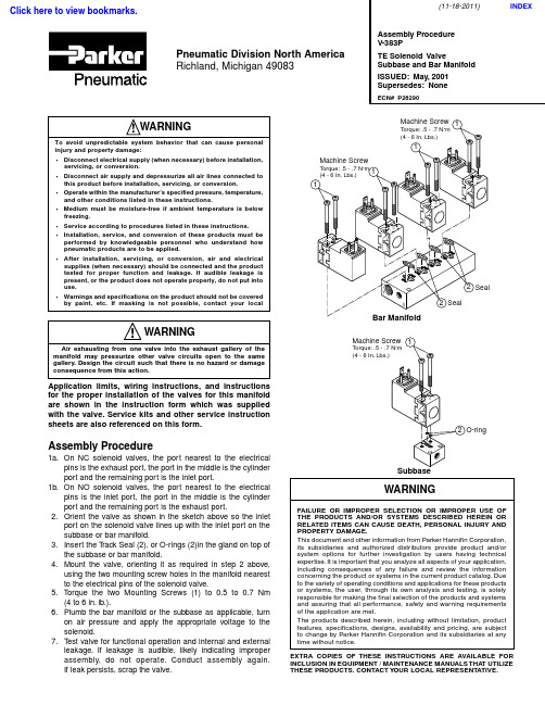
Assembly Procedure1a.On NC solenoid valves, the port nearest to the electricalpins is the exhaust port, the port in the middle is the cylinder port and the remaining port is the inlet port.1b.On NO solenoid valves, the port nearest to the electricalpins is the inlet port, the port in the middle is the cylinder port and the remaining port is the exhaust port.2.Orient the valve as shown in the sketch above so the inletport on the solenoid valve lines up with the inlet port on the subbase or bar manifold.3.Insert the T rack Seal (2), or O-rings (2)in the gland on top ofthe subbase or bar manifold.4.Mount the valve, orienting it as required in step 2 above,using the two mounting screw holes in the manifold nearest to the electrical pins of the solenoid valve.5.T orque the two Mounting Screws (1) to 0.5 to 0.7 Nm(4 to 6 in. lb.).6.Plumb the bar manifold or the subbase as applicable, turnon air pressure and apply the appropriate voltage to the solenoid.7.T est valve for functional operation and internal and externalleakage. If leakage is audible, likely indicating improper assembly, do not operate. Conduct assembly again.If leak persists, scrap the valve.Application limits, wiring instructions, and instructions for the proper installation of the valves for this manifold are shown in the instruction form which was supplied with the valve. Service kits and other service instruction sheets are also referenced on this form.!WARNINGAir exhausting from one valve into the exhaust gallery of the manifold may pressurize other valve circuits open to the same gallery. Design the circuit such that there is no hazard or damage consequence from this action.Assembly Procedure V -383PTE Solenoid ValveSubbase and Bar Manifold ISSUED: May, 2001Supersedes: NoneECN# P28290Pneumatic Division North America Richland, Michigan 49083WARNINGFAILURE OR IMPROPER SELECTION OR IMPROPER USE OF THE PRODUCTS AND/OR SYSTEMS DESCRIBED HEREIN OR RELATED ITEMS CAN CAUSE DEATH, PERSONAL INJURY AND PROPERTY DAMAGE.This document and other information from Parker Hannifin Corporation,its subsidiaries and authorized distributors provide product and/or system options for further investigation by users having technical expertise. It is important that you analyze all aspects of your application,including consequences of any failure and review the information concerning the product or systems in the current product catalog. Due to the variety of operating conditions and applications for these products or systems, the user, through its own analysis and testing, is solely responsible for making the final selection of the products and systems and assuring that all performance, safety and warning requirements of the application are met.The products described herein, including without limitation, product features, specifications, designs, availability and pricing, are subject to change by Parker Hannifin Corporation and its subsidiaries at any time without notice.EXTRA COPIES OF THESE INSTRUCTIONS ARE AVAILABLE FOR INCLUSION IN EQUIPMENT / MAINTENANCE MANUALS THA T UTILIZE THESE PRODUCTS. CONTACT YOUR LOCAL REPRESENTATIVE.!WARNINGTo avoid unpredictable system behavior that can cause personal injury and property damage:•Disconnect electrical supply (when necessary) before installation,servicing, or conversion.•Disconnect air supply and depressurize all air lines connected to this product before installation, servicing, or conversion.•Operate within the manufacturer’s specified pressure, temperature,and other conditions listed in these instructions.•Medium must be moisture-free if ambient temperature is below freezing.•Service according to procedures listed in these instructions.•Installation, service, and conversion of these products must be performed by knowledgeable personnel who understand how pneumatic products are to be applied.•After installation, servicing, or conversion, air and electrical supplies (when necessary) should be connected and the product tested for proper function and leakage. If audible leakage is present, or the product does not operate properly, do not put into use.•Warnings and specifications on the product should not be covered by paint, etc. If masking is not possible, contact your local12O-ringMachine ScrewTorque: .5 - .7 N·m (4 - 6 In. Lbs.)Subbase11(11-18-2011)INDEXClick here to view bookmarks.TE Solenoid Valve Subbase and Bar Manifold V-383PWiringAttach an electrical cable with connector (that conforms to the DIN 43650, Form C pattern) to the terminals of the solenoid. For locations in a cabinet or other protected environment, the Snap-On connector with loose wires may be attached. In both cases, do not attach or remove the connectors until power is off. Follow all requirements for local and national electrical codes. Electrical Connection:Valves with 3-pin male terminals should have power connected to the parallel terminals. Ground should be connected to the perpendicular terminal. Use only connectors that comply with DIN 43650, Form C (8mm blade spacing). Accessories:Kit No.DescriptionPS298305P Snap on Connector Kit with 0.5 meter wiresPS298320P Snap on Connector Kit with 2 meter wiresPS2932P3-Pin Connector Kit - UnlightedPS294675P3-Pin Connector Kit - Lighted, 12VAC & DCPS294679P3-Pin Connector Kit - Lighted, 24VAC & DCPS294683P3-Pin Connector Kit - Lighted, 120VACPS2932JP3-Pin Connector Kit - Unlighted with2 meter cordPS2946J75P3-Pin Connector Kit - Lighted, 12VAC & DC with2 meter cordPS2946J79P3-Pin Connector Kit - Lighted, 24VAC & DC with2 meter cordPS2946J83P3-Pin Connector Kit - Lighted, 120VAC with2 meter cord Service Kits AvailableThe following service kits contain the appropriate seals and parts necessary for ordinary field service.Kit No.DescriptionNormally ClosedPS2982AXXP Solenoid Kit - No OverridePS2982BXXP Solenoid Kit - Non-Locking Flush OverridePS2982CXXP Solenoid Kit - Locking Flush OverridePS2982DXXP Solenoid Kit - Non-Locking Extended Override PS2982EXXP Solenoid Kit - Locking Extended OverrideNormally OpenPS3202BXXP*Solenoid Kit - Non-Locking Flush Override*Only available for voltage codes 42,45,49 & 53.When ordering solenoid service kits specify two digit solenoid voltage code (XX). Code keys are as given below:XX - Voltage Code KeyCode Voltage4012 Volt 60Hz, 12 Volt 50Hz4224 Volt 60Hz, 22 Volt 50Hz4512 Volt DC4924 Volt DC53120 Volt 60Hz, 115 Volt 50HzPneumatic DivisionRichland, Michigan 49083 269-629-5000PDNSG-1Safety Guide For Selecting And Using Pneumatic Division Products And Related AccessoriesWARNING:FAILURE OR IMPROPER SELECTION OR IMPROPER USE OF PNEUMATIC DIVISION PRODUCTS, ASSEMBLIES OR RELATED ITEMS (“PRODUCTS”) CAN CAUSE DEATH, PERSONAL INJURY, AND PROPERTY DAMAGE. POSSIBLE CONSEQUENCES OF FAILURE OR IMPROPER SELECTION OR IMPROPER USE OF THESE PRODUCTS INCLUDE BUT ARE NOT LIMITED TO:• Unintended or mistimed cycling or motion of machine members or failure to cycle • Work pieces or component parts being thrown off at high speeds.• Failure of a device to function properly for example, failure to clamp or unclamp an associated item or device.• Explosion• Suddenly moving or falling objects.• Release of toxic or otherwise injurious liquids or gasses.Before selecting or using any of these Products, it is important that you read and follow the instructions below.1. GENERAL INSTRUCTIONS1.1. Scope: This safety guide is designed to cover general guidelines on the installation, use, and maintenance of Pneumatic Division Valves, FRLs (Filters, Pressure Regulators, and Lubricators), Vacuum products and related accessory components.1.2. Fail-Safe: Valves, FRLs, Vacuum products and their related components can and do fail without warning for many reasons. Design all systems and equipment in a fail-safe mode, so that failure of associated valves, FRLs or Vacuum products will not endanger persons or property.1.3 Relevant International Standards: For a good guide to the application of a broad spectrum of pneumatic fluid power devices see: ISO 4414:1998, Pneumatic Fluid Power – General Rules Relating to Systems. See for ordering information.1.4. Distribution: Provide a copy of this safety guide to each person that is responsible for selection, installation, or use of Valves, FRLs or Vacuum products. Do not select, or use Parker valves, FRLs or vacuum products without thoroughly reading and understanding this safety guide as well as the specific Parker publications for the products considered or selected.1.5. User Responsibility: Due to the wide variety of operating conditions and applications for valves, FRLs, and vacuum products Parker and its distributors do not represent or warrant that any particular valve, FRL or vacuum product is suitable for any specific end use system. This safety guide does not analyze all technical parameters that must be considered in selecting a product. The user, through its own analysis and testing, is solely responsible for: • Making the final selection of the appropriate valve, FRL, Vacuum component, or accessory. • Assuring that all user’s performance, endurance, maintenance, safety, and warning requirements are met and that the application presents no health or safety hazards. • Complying with all existing warning labels and / or providing all appropriate health and safety warnings on the equipment on which the valves, FRLs or Vacuum products are used; and, • Assuring compliance with all applicable government and industry standards. 1.6. Safety Devices: Safety devices should not be removed, or defeated.1.7. Warning Labels: Warning labels should not be removed, painted over or otherwise obscured.1.8. Additional Questions: Call the appropriate Parker technical service department if you have any questions or require any additional information. See the Parker publication for the product being considered or used, or call 1-800-CPARKER, or go to , for telephone numbers of the appropriate technical service department.2. PRODUCT SELECTION INSTRUCTIONS2.1. Flow Rate: The flow rate requirements of a system are frequently the primary consideration when designing any pneumatic system. System components need to be able to provide adequate flow and pressure for the desired application.2.2. Pressure Rating: Never exceed the rated pressure of a product. Consult product labeling, Pneumatic Division catalogs or the instruction sheets supplied for maximum pressure ratings.2.3. Temperature Rating: Never exceed the temperature rating of a product. Excessive heat can shorten the life expectancy of a product and result in complete product failure.2.4. Environment: Many environmental conditions can affect the integrity and suitability of a product for a given application. Pneumatic Division products are designed for use in general purpose industrial applications. If these products are to be used in unusual circumstances such as direct sunlight and/or corrosive or caustic environments, such use can shorten the useful life and lead to premature failure of a product.2.5. Lubrication and Compressor Carryover: Some modern synthetic oils can and will attack nitrile seals. If there is any possibility of synthetic oils or greases migrating into the pneumatic components check for compatibility with the seal materials used. Consult the factory or product literature for materials of construction.2.6. Polycarbonate Bowls and Sight Glasses: To avoid potential polycarbonate bowl failures: • Do not locate polycarbonate bowls or sight glasses in areas where they could be subject to direct sunlight, impact blow, or temperatures outside of the rated range. • Do not expose or clean polycarbonate bowls with detergents, chlorinated hydro-carbons, keytones, esters or certain alcohols. • Do not use polycarbonate bowls or sight glasses in air systems where compressors are lubricated with fire resistant fluids such as phosphate ester and di-ester lubricants.!PDNSG-1Pneumatic Division Safety Guide ISSUED: August 1 , 2006Supersedes: June 1, 2006Pneumatic Division Safety Guide2.7. Chemical Compatibility: For more information on plastic component chemical compatibility see Pneumatic Division technical bulletinsTec-3, Tec-4, and Tec-52.8. Product Rupture: Product rupture can cause death, serious personal injury, and property damage.• Do not connect pressure regulators or other Pneumatic Division products to bottled gas cylinders.• Do not exceed the maximum primary pressure rating of any pressure regulator or any system component.• Consult product labeling or product literature for pressure rating limitations.3. PRODUCT ASSEMBLY AND INSTALLATION INSTRUCTIONS3.1. Component Inspection: Prior to assembly or installation a careful examination of the valves, FRLs or vacuum products must beperformed. All components must be checked for correct style, size, and catalog number. DO NOT use any component that displays any signs of nonconformance.3.2. Installation Instructions: Parker published Installation Instructions must be followed for installation of Parker valves, FRLs andvacuum components. These instructions are provided with every Parker valve or FRL sold, or by calling 1-800-CPARKER, or at.3.3. Air Supply: The air supply or control medium supplied to Valves, FRLs and Vacuum components must be moisture-free if ambienttemperature can drop below freezing4. VALVE AND FRL MAINTENANCE AND REPLACEMENT INSTRUCTIONS4.1. Maintenance: Even with proper selection and installation, valve, FRL and vacuum products service life may be significantly reducedwithout a continuing maintenance program. The severity of the application, risk potential from a component failure, and experience with any known failures in the application or in similar applications should determine the frequency of inspections and the servicing or replacement of Pneumatic Division products so that products are replaced before any failure occurs. A maintenance program must be established and followed by the user and, at minimum, must include instructions 4.2 through 4.10.4.2. Installation and Service Instructions: Before attempting to service or replace any worn or damaged parts consult the appropriateService Bulletin for the valve or FRL in question for the appropriate practices to service the unit in question. These Service andInstallation Instructions are provided with every Parker valve and FRL sold, or are available by calling 1-800-CPARKER, or by accessing the Parker web site at .4.3. Lockout / Tagout Procedures: Be sure to follow all required lockout and tagout procedures when servicing equipment. For moreinformation see: OSHA Standard – 29 CFR, Part 1910.147, Appendix A, The Control of Hazardous Energy – (Lockout / Tagout)4.4. Visual Inspection: Any of the following conditions requires immediate system shut down and replacement of worn or damagedcomponents:• Air leakage: Look and listen to see if there are any signs of visual damage to any of the components in the system. Leakage is an indication of worn or damaged components.• Damaged or degraded components: Look to see if there are any visible signs of wear or component degradation.• Kinked, crushed, or damaged hoses. Kinked hoses can result in restricted air flow and lead to unpredictable system behavior.• Any observed improper system or component function: Immediately shut down the system and correct malfunction.• Excessive dirt build-up: Dirt and clutter can mask potentially hazardous situations.Caution: Leak detection solutions should be rinsed off after use.4.5. Routine Maintenance Issues:• Remove excessive dirt, grime and clutter from work areas.• Make sure all required guards and shields are in place.4.6. Functional Test: Before initiating automatic operation, operate the system manually to make sure all required functions operateproperly and safely.4.7. Service or Replacement Intervals: It is the user’s responsibility to establish appropriate service intervals. Valves, FRLs and vacuumproducts contain components that age, harden, wear, and otherwise deteriorate over time. Environmental conditions can significantly accelerate this process. Valves, FRLs and vacuum components need to be serviced or replaced on routine intervals. Service intervals need to be established based on:• Previous performance experiences.• Government and / or industrial standards.• When failures could result in unacceptable down time, equipment damage or personal injury risk.4.8. Servicing or Replacing of any Worn or Damaged Parts: To avoid unpredictable system behavior that can cause death, personalinjury and property damage:• Follow all government, state and local safety and servicing practices prior to service including but not limited to all OSHA Lockout Tagout procedures (OSHA Standard – 29 CFR, Part 1910.147, Appendix A, The Control of Hazardous Energy – Lockout / Tagout).• Disconnect electrical supply (when necessary) before installation, servicing, or conversion.• Disconnect air supply and depressurize all air lines connected to system and Pneumatic Division products before installation, service, or conversion.• Installation, servicing, and / or conversion of these products must be performed by knowledgeable personnel who understand how pneumatic products are to be applied.• After installation, servicing, or conversions air and electrical supplies (when necessary) should be connected and the product tested for proper function and leakage. If audible leakage is present, or if the product does not operate properly, do not put product orsystem into use.• Warnings and specifications on the product should not be covered or painted over. If masking is not possible, contact your localrepresentative for replacement labels.4.9. Putting Serviced System Back into Operation: Follow the guidelines above and all relevant Installation and Maintenance Instructionssupplied with the valve FRL or vacuum component to insure proper function of the system.。
液压设备安装调试操作手册1

液压设备安装调试操作手册柳州欧维姆工程股份有限公司1、LSD液压提升系统提升工艺流程2、液压系统设备安装工艺要求3、液压提升系统运行4、钢绞线使用的注意事项5、构件夹持器的使用注意事项1、LSD液压提升系统提升工艺流程1)配制LSD200顶每台千斤顶需用钢绞线 16根,其中左旋、右旋钢绞线各 8 根,每根钢索的长度约为107米;2)用承吊装置将千斤顶吊到承重平台安装就位。
3)按本工程设计的液压提升油路连接:千斤顶与阀体柜;阀体柜与泵站;千斤顶与泵站泄油回路;4)按本工程设计的控制系统电路连接:控制系统与千斤顶; 控制系统与阀体柜;控制系统与泵站;5)液压提升系统初步调试:手动控制调试、自动控制调试;6)安装钢绞线导线架;7)承重系穿索;8)预紧索:单根预紧,整体预紧;用螺钉压紧导向锚压板;9)液压提升系统试运行,手动运行操作试提升一个小距离并调整构件平衡;10)手动调整新的构件平衡;再次紧固导向锚压板螺钉;11)进入正式提升:手动调整、自动运行;12)提升到位13)构件拼装,提升完成;14)等焊接完成,重复提升,直到烟囱到位。
2、液压系统设备安装工艺要求1、千斤顶安装千斤顶安装方法,把千斤顶吊装到位,后再穿索;A、千斤顶安装时其底座安装平面与承重梁交合面不能有目视的缝隙B、液控单向阀的方位必须朝向有利于油管连接的方向C、千斤顶轴线与钢绞线的夹角应小于等于30D、钢绞线穿索使用卷扬机提升辅助穿入时,由于穿索处与卷扬机操作位置分处两地,必须作好应答联络,确认明白操作意图,才可实施操作E、导线架: 导线架承接从千斤顶伸出的钢绞线的接线入口必须在导向锚正上方1米以上;从导向锚伸出的钢绞线在导线架上导向的弯曲直径必须大于3米,,且具有足够的钢度承载伸出钢绞线在导线架上间断移动F、构件夹持器与构件的交合面不能有目视的缝隙,吊具的焊缝不能顶住构件夹持器2、液压系统A、泵站放置方向必须方便操作,其油管导出的方向需是通向阀体柜的方向B、阀体柜的放置方向必须确认其千斤顶的方向和泵站的方向,调速阀必须朝向方便调节的方向C、油管安装前必须确认其安装端头部分必须是清洁地,否则安装前必须清洗D、油管连接分两个部分,第一部分为泵站至阀体柜,第二部分为阀体柜至千斤顶,各部分的连接必须按其设计编号一一对应E、千斤顶泄油管必须接回泵站3、控制系统A、电缆线:电缆线安装时必须按顺序放盘、收盘,高空安装时,由于电缆线太长应尽可能在空中做多点分段固定;B、接近开关: 感应式接近开关安装其感应头与感应体的距离小于2毫米,用透明胶带做好感应头部位与尾部部位的防雨;机械式行程开关应在夹持器压紧时接触接通再下移约2mm处固定;D、电缆线的连接分四个部分,第一部分为控制柜至千斤顶,其控制电缆的编号为X201~X210;第二部分为控制柜至阀体柜,其控制电缆的编号为X301~X304; 第三部分为控制柜至泵站,其控制电缆的编号为X401~X403;用接插件实现各部分连接, 接插件应绝对按设计编号一一连接正确,试机前必须反复检查连接的正确性,并做好接插件的防雨措施3、液压提升系统运行1.提升系统运行前的准备、检查工作·各个位置行程开关安装位置测试·千斤顶所对应编码仪行程测量值校验,编码仪的安装正确,要求拉绳与千斤顶轴线平行,在回程到位时拉绳应拉出编码仪1cm(选项)·提升时,导向夹持器是否处于自由松弛状态,下放时,导向夹持器与安全夹持器的夹片将处于支起状态·伸出钢绞线的导线架装置符合导出钢绞线重量的强度要求,牢固可靠·手触钢绞线,要求受力均匀、不能打绞、外观整洁;·钢绞线与千斤顶轴线的偏角在规定范围内·构件夹持器安装正确,压板受力均匀,与构件安装孔对中·泵站油位正常,各个液压回路的压力值调整到正确范围内,泵站流量调为设计值·在倒装过程施工中,每个节段提升前需要确认提升重量,确定本次提升的压力值·各岗位设备备件齐备,工具齐备2. 提升系统运行时各个岗位的工作职责提升施工的过程是一个融合手动控制、自动控制运行的一个复杂的过程,选择何种控制运行方式是按施工中正在进行的工况来决定的,无论如何操作控制提升设备运行,其各个监视点都有其工作的基本内容;除对整个构件的运行过程进行动态测量监视外,在提升系统设备这部分,其监视面可分为三个部分,第一为主控制台;第二为承重吊点;第三为动力泵站;其各个岗位的工作职责如下:A、主控台·监视系统在自动过程中在主控台显示的各个状态信号步骤相符·自动过程中在主控台显示的进程按与LSD提升工法正确步进·编码仪测量数据平衡在正确范围内·各个行程开关信号输入状态正常·检查、收集处理分析各吊点的油压表变化情况·各输出通道数据正常·观测调节点、调节阀自动调节变化的频率·按工况要求手动控制操作设备实现提升、调整和下放B、承重吊点·千斤顶主缸及夹持器油缸是否按LSD提升工法步骤正确伸缩及松紧·各个位置感应行程开关在主缸伸缩感应的过程中是否正确点亮和熄灭·夹持器位置行程开关在夹持器松紧动作的过程中是否正确放松和压紧·各个夹持器拔松、压紧是否有异响·千斤顶夹持器夹片在压紧的过程中是否被挤压,夹片螺钉是否有断裂,夹片端面是否与压板平齐·千斤顶上编码仪行程拉线是否正确伸长、收紧,并在伸长、收紧过程没有旋转(选项)各接近开关在感应板经过时尾灯亮,反之尾灯熄;接近开关与感应板的接近安装距离应小与2mm;·钢绞线是否有严重损伤;伸出钢绞线的咬痕是否正常;对于千斤顶内腔无导向管的千斤顶,在千斤顶缩缸时钢绞线是否回缩而产生窝缸;对于在夹持器停止油路没带有截止的中位Y型电磁阀泵站系统,必须注意在负载转换时,其夹片是否随钢绞线的振动而产生微动·提升时,导向夹持器是否处于自由松弛状态,并随钢绞线伸出而放松,随主缸回程而承力;下放时,夹片将处于支起状态·各个液压回路液压油没有泄漏·在各动作的过程中各个千斤顶动作是否同步,是否有异常声响·同一吊点的伸缸速是否相同·安全锚位置是否正常,其锚板下部是否固定在承力梁上,不能随钢绞线向上移动;提升时,夹片将处于自由松弛状态;下放时,夹片将处于支起状态·监视阀体柜中压力油表值及其变动是否超越正常值,并与提升需用力值匹配C、动力液压泵站·主缸油压按提升重量要求,油表值是否在规定控制值的±2 MP的范围内;泵站上主缸压力油表摆动是否正常·检查夹持器油压调整在2.0~3.5Mpa·泵站油位是否大于显示管1/2显示值·各个油路、阀体是否有卸漏3. 提升系统运行时的环境要求A、遇有大风、大雾、雷雨等天气,不得进行吊装作业,风力大于8级不能实施吊装作业B、夜间不得实施吊装作业,如在特殊紧急情况下,必须具有足够的照明设施,保证每一台千斤顶、每一台泵站、控制系统和吊件具有足够的照明设施,并加强对整个吊装系统的监控力度C、与提升系统吊装过程发生相互交叠危险、干扰危险的工作面必须暂停4、钢绞线使用的注意事项1、钢绞线是提升装置的关键承力部件,要求不能有严重刮伤、严禁有焊渣吸附在钢绞线上;多次使用的钢绞线再使用时,需检查表面无严重咬伤和松股、严重锈蚀等缺陷,并作相应试验和取得监理工程师认可2、钢绞线不允许通过滑轮转向或在任何弯曲的状态下受力,钢绞线在自然状态下有弯折存在时禁止使用3、导线架承接从千斤顶伸出的钢绞线的接线入口必须在导向锚正上方1米以上;从导向锚伸出的钢绞线在导线架上导向的弯曲直径必须大于3米,在导线架上的弯曲直径必须大于3米, 从导向锚伸出的钢绞线垂直长度大于80厘米;当钢绞线下垂长度大于20米应用倒链或葫芦和钢丝绳适度提起下垂的钢绞线,使钢绞线提升时从导向锚伸出时减少导线架的压力;4、钢绞线有左右旋之分,穿装时应左右旋向间隔一一穿入5、钢绞线不允许露天放置,必须做好防雨、防潮、防污染措施6、切割下来的钢绞线,应及时穿于千斤顶上,如要暂时存放,要禁止车辆及其他重物碾压,防止粘上污物泥土及损伤7、处理单根钢绞线时,必须按钢绞线状况用绳夹分别扣紧钢绞线两端头(或一端),防止钢绞线在处理中不小心坠落5.构件夹持器的使用注意事项1、构件夹持器是承载钢绞线与吊装件连接的关键部件,穿入的钢绞线必修与千斤顶上的设计编号一一对应,不准错位、不准中间交叉、不准扭转2、按梳线板分布梳理钢绞线穿入构件夹持器时,钢绞线不能抽出梳线板3、构件夹持器的锥孔要预先擦净,在锥孔内均匀涂上退锚灵4、每个构件夹持器做完成后,必须立即与吊装件定位,防止构件夹持器再次打转5、当试运行时,随着构件夹持器逐步承载,构件夹持器的限位压板也要逐步跟进拧紧6、夹持器安装时必须一孔、一索、一副夹片,同一夹持器的夹片必须选择同一型号的夹片,不能错装及漏装LSD 千斤顶提升工法流程图1.紧下锚所下锚是否到位2.缩缸(非同步)所有主缸是否都回到①位3.紧上锚所有上锚是否夹紧延时紧上锚10秒4.同步伸缸5.同步伸缸、松下锚下锚是否松开6.同步伸缸否是否是否所有主缸是否都到达②位否是否是所有主缸是否都到达④位紧下锚停机11.紧上锚所有上锚是否夹紧停机?是所有主缸是否都到达①位所有上锚是否松开否是10.非同步缩缸否9.非同步缩缸、松上锚是所有主缸是否都回到③位否否8.缩缸(非同步)所下锚是否到位是7.停止伸缸、紧下锚否是延时紧下锚10秒是否是否LSD 千斤顶下降工法流程图所有主缸是否都到达④位是所有主缸是否都到达③位是延时紧上锚10秒6.同步伸缸所有上锚是否夹紧5.紧上锚是4.非同步伸缸所有上锚是否松开到位2.缩缸(非同步)所有主缸是否都回到①位3.松上锚是1.紧下锚所下锚是否到位是停机延时紧下锚10秒否停机?10.非同步缩缸所有主缸是否都到达①位紧下锚否否否是是否8.同步缩缸9.紧下锚所有下锚是否夹紧所有主缸是否都回到②位否否是否是否7.停止伸缸、松下锚所有下锚是否松开到位否是否。
液压系统的安装、调试、维护(详细介绍)
液压系统的安装液压系统的安装液压系统安装质量的好坏是关系到液压系统能否可靠工作的关键。
必须科学、正常、合理地完成安装过程中的每个环节,才能使液压系统能够正常运行;充分发挥其效能。
2.1 安装前的准备工作1)明确安装现场施工程序及施工进度方案。
2)熟悉安装图样,掌握设备分布及设备基础情况。
3)落实好安装所需人员、机械、物资材料的准备工作。
4)做好液压设备的现场交货验收工作,根据设备清单进行验收。
通过验收掌握设备名称、数量、随机备件、外观质量等情况,发现问题及时处理。
5)根据设计图纸对设备基础和预埋件进行曲检查,对液压设备地脚尺寸进行复核,对不符合要求的地方进行处理,防止影响施工进度。
2.2 液压设备的就位1)液压设备应根据平面布置图对号吊装就位,大型成套液压设备,应由里向外依次进行吊装。
2)根据平面布置图测量调整设备安装中心线及标高点,可通过调整安装螺栓旁的垫板达到将设备调平找正,达到图纸要求。
3)由于设备基础相关尺寸存在误差,需在设备就位后进行微调,保证泵吸油管处于水平、正直对接状态,4)油箱放油口及各装置集油盘放污口应在设备微调时给予考虑,应是设备水平状态时的最低点。
5)应对安装好的设备做适当防护,防止现场脏物污染系统。
6)设备就位调整完成后,一般需对设备底座下面进行混凝土浇灌,即二次灌浆。
2.3 液压配管(1)管材选择应根据系统压力及使用场合来选择管材。
必须注意管子的强度是否足够,管径和壁厚是否符合图纸要求,所选用的无缝钢管内壁必须光洁、无锈蚀、无氧化皮、无夹皮等缺陷。
若发现下列情况不能使用:管子内外壁已严重锈蚀。
管体划痕深度为壁厚的10%以上;管体表面凹入达管径的20%以上;管断面壁厚不均、椭圆度比较明显等。
中、高压系统配管一般采用无缝钢管,因其具有强度高、价格低、易于实现无泄漏连接等优点,在液压系统中被广泛使用。
普通液压系统常采用冷拔低碳钢10、15、20号无缝管,此钢号配管时能可靠地与各种标准管件焊接。
1.5MW风力发电机组液压系统安装、维护指导书(哈威被动式)
1.5MW风力发电机组液压系统安装、维护指导书(哈威被动式)目录1. 液压系统说明 (1)2. 液压系统的基本构成 (2)3. 液压系统功能说明 (3)4. 液压站压力值 (3)5. 液压系统元件 (3)6. 安装位置和电器接线 (5)7. 液压系统的安装 (5)8.液压系统的调试、保养与维修 (6)9. 常见故障的诊断及消除方法 (7)1. 液压系统说明东汽风力发电机的液压站系统属于风力发电机的一种刹车动力系统,它的主要功能是为偏航制动和主轴制动装置提供液压驱动力。
风机液压站系统是一个公共服务系统,它为风力发电机上一切使用液压作为驱动力装置提供动力。
1.1液压系统常识(一)、液压工作原理液压装置的工作原理是:在特定的机械、电子设备内,利用液体介质的静压力,完成能量的蓄积、传递、控制、放大,实现机械功能的轻巧化、精细化、科学化和最大化。
(二)、液压技术的特点:液压系统的基本功能是以液体压力能的形式进行便于控制的能量传递。
从能量传递方面看,液压技术大致处于机械式能量传递和电气式能量传递之间位置。
1.2液压技术的特点如下:1、可实现大范围的无级调速(调速范围达2000:1),即能在很宽的范围内很容易地调节力与转矩;2、控制性能好,对力、速度、位置等指标能以很高的响应速度正确地进行控制。
很容易实现机器的自动化,当采用电液联合控制时,不仅可实现更高程度的自动控制过程,而且可以实现遥控。
3、体积小、重量轻、运动惯性小、反应速度快,动作可靠,操作性能好。
4、可自动实现过载保护。
一般采用矿物油作为工作介质,相对运动面可自行润滑,使用寿命长。
5、可以方便地根据需要使用液压标准元件、灵活地构成实现任意复杂功能的系统。
2. 液压系统的基本构成系统的组成部分称为液压元件,根据液压元件的功能分类如下:1、动力元件动力元件的作用是将原动机的机械能转换成液体(主要是油)的压力能,是指液压系统中的油泵,向整个液压系统提供压力油。
- 1、下载文档前请自行甄别文档内容的完整性,平台不提供额外的编辑、内容补充、找答案等附加服务。
- 2、"仅部分预览"的文档,不可在线预览部分如存在完整性等问题,可反馈申请退款(可完整预览的文档不适用该条件!)。
- 3、如文档侵犯您的权益,请联系客服反馈,我们会尽快为您处理(人工客服工作时间:9:00-18:30)。
NC475液压系统
安装说明书
NBU69-AM
审定
审核
校对
编制
共 1 册复用 1 册本册页 6
二OO七年二月
目录
1 总述……………………………………………………………( 1 )
2 液压站组装……………………………………………………( 1 )
3 管道安装………………………………………………………( 1 )
4 管道酸洗、冲洗………………………………………………( 4 )
5 压力试验………………………………………………………( 5 )
6 设备要求………………………………………………………( 6 )
1 总述
随着篦冷机的日益大型化,液压传动技术在篦冷机上得到了广泛的应用。
相比于机械传动,液压传动结构紧凑、调速方便、运行平稳,能够适应设备复杂多变的工况,可靠性好,运行效率高。
相对于其性能的优越性,由于该系统是电液比例系统,因此该系统对安装的要求更高。
液压管道的安装及清洗是该液压设备安装的关键,管道安装质量、油液的清洁度是关系到系统能否正常工作的关键。
为了保证技术规范的统一性和完整性,特编制该说明书。
请施工单位、用户严格按此说明书的要求施工,任何不按此说明书要求施工而产生的后果,责任均不在供货方。
2 液压站组装
到货的液压站是有几部分组成的,需要在现场将它们组装到一起。
组装时要特别注意,决不能让任何污物(包括粉尘)从接口处进入系统内部,并保证接口处不得有任何漏油现象。
3 管道安装
3.1 切割
◇液压的管子一般应用机械方法切割;
◇管子切割表面必须平整,不得有裂纹、重皮。
管端的切屑粉、毛刺、熔渣、氧化皮等必须清除干净。
◇切口平面与管子轴线垂直度公差为管子外径的1/100.
3.2 弯管
◇液压、润滑系统的管子一般采用冷弯。
◇弯管的最小弯曲半径应采用处径的3倍,管子工作压力高,弯曲半径宜大。
管子弯曲处应圆滑,不应有明显的凹痕、波纹及压扁现象。
3.3管道焊接
※管道焊接要求采用氩弧焊焊接或用氩弧焊打底、电弧焊填充
3.3.1 焊缝质量要求
◇工作压力等于及高于6.3MPa(63Bar)的管道,其对口焊缝质量应不低于Ⅰ级焊缝标准;工作压力低于6.3MPa的管道,其对口焊缝质量应不低于Ⅱ级焊缝标准。
此液压系统管道焊缝质量要求不低于Ⅰ级焊缝标准。
3.3.2 坡口加工及接头组对
◇焊缝的破口应用机械方法加工,其加工形式、加工方法和尺寸标准等均应符合GB/T985、GB/T986的有关规定。
可用砂轮打磨坡口,但绝不允许用氧-乙炔焰加工,加工后不允许有影响焊接质量的凹凸不平处。
◇管子、管件的对口应做到内壁平齐:Ⅰ、Ⅱ级焊缝的对口,内壁错边量应不超过管壁厚度的10%,且不大于14mm;
3.3.3 管道焊接
◇管道焊接应采用氩弧焊焊接或用氩弧焊打底、电弧焊填充。
◇焊工应按有关规定进行考试,取得所施焊范围的合格证书后
方能参加本施焊范围的焊接工作。
◇焊接材料应具有制造厂的合格证明书。
◇焊条、焊剂在使用前应按产品说明书的规定烘干,并在使用过程中保持干燥,焊条药皮应无脱落和显著裂纹。
◇焊丝在使用前应清除表面的油污、锈蚀等。
◇施焊前应对坡口及附近宽20mm范围内的内外管壁进行清理,除净其上的油、水、漆及毛刺等。
◇管道点固焊时,点固的工艺措施及焊接材料应与正式焊接一致。
点固焊后应认真检查焊肉,如发现有裂纹等缺陷,应及时处理。
◇在管道焊接全过程中,应防止风、雨、雪的侵袭。
◇焊接完毕,应将焊缝表面熔渣及其两侧的飞溅清理干净,并做好记录。
◇焊缝的返修应有工艺措施;同一焊缝的返修次数:管道不得超过3次;
3.3.4 焊接检验
◇管道对口焊接后必须进行外观检查,且应在无损探伤和压力试验前进行;
◇检查前应将妨碍检查的渣皮和飞溅清理干净。
◇按规定比例探伤不合格者,应加倍抽查焊工的焊缝,如仍有不合格者,则应对该焊工的全部焊缝进行无损探伤。
◇角焊缝的焊脚高度应符合设计规定,其外形应平缓过渡,表
面不得有裂纹,气孔,夹渣等缺陷,咬肉深度不得大于0.5mm。
4 管道酸洗、冲洗
4.1 管道酸洗
管道的酸洗和冲洗是保证液压系统工作可靠性和元件使用寿命的关键环节之一,必须给予足够的重视。
应按《机械设备安装工程及验收通用规范》(GB50231)、《重型机械液压系统通用技术条件》(JB/T6996)等有关规范进行。
建议将焊好的管道拆下后送到有专业酸洗槽的专业公司进行酸洗!如确需在现场酸洗,应向供货方咨询。
4.2 循环冲洗
◇管道在酸洗合格后进行冲洗,冲洗一般以循环方式进行。
◇管道可用与该系统工作同一型号的液压油进行独立冲洗,冲洗时管道两端禁止与液压站及液压缸连接。
◇冲洗液的冲洗流速应使液流呈紊流状态,且流速尽可能高。
◇冲洗时油温不宜超过60℃,在不超过该温度下,冲洗的油温宜高。
◇循环冲洗要连续进行,冲洗时间通常在72小时以上,冲洗过程宜采用改变冲洗方向或对焊接处和管子反复地进行敲打、
振动等方法加强冲洗效果。
◇冲洗过程应经常检查滤芯,随时准备更换滤芯。
◇冲洗结束后,必须采用颗粒计数法对管道回油口冲洗液进行
检验,其清洁度不应低于JB/T6996-1993规定的16/13(相当于NAS 1638 7级)。
◇管道冲洗完成后,当要拆卸接头时,应立即封口;当需对管口焊接处理时,对该管道应重新进行酸洗和冲洗。
5 压力试验
◇系统的压力试验应在冲洗合格后进行。
◇压力试验介质可用系统工作的液压油和泵组,液压油应通过滤油小车过滤后加入油箱,且滤油小车过滤精度不应低于系统的过滤精度。
◇压力试验时,应先作低压循环,并排净系统中的空气。
◇压力试验时的油温应在正常工作油温范围之内。
◇试验压力应逐级升高,每升高一级宜稳压至2~3分钟,达到试验压力(25MPa)后,持压10分钟,然后降至工作压力进行全面检查,以系统所有焊缝、连接口和密封处无漏油,管道无永久变形为合格。
◇压力试验时如有故障需要处理,必须先卸压;如有焊缝需要重焊,必须将该管卸下并在除净油液后方可焊接。
◇压力试验期间不得锤击管道,且在试验区域周围5m范围内不得同时进行明火作业及重噪声作业。
◇压力试验应有试验规程,试验完毕后应填写《系统压力试验记录》。
6 设备要求:(用户自备)
1.加油小车(建议LUC-100×5Q 1台黎明液压)
(黎明液压)滤芯CWU-100×100J 2只 CZX-100×5Q 2只。
2.L-HM46抗磨液压油(无灰)或N46抗磨液压油共15桶(每桶
170㎏),其中冲洗用油3桶,工作用油12桶,清洁度要求(NAS
1638 7级)。
