LN2543最新规格书(中文版)
TLV2543CN;TLV2543CDBR;TLV2543CDW;TLV2543IDB;TLV2543IDW;中文规格书,Datasheet资料

Terminal Functions
TERMINAL NAME AIN0 – AIN10 NO. 1 – 9, 11, 12 15 I/O I DESCRIPTION Analog input. These 11 analog-signal inputs are internally multiplexed. The driving source impedance should be less than or equal to 50 Ω for 4.1-MHz I/O CLOCK operation and capable of slewing the analog input voltage into a capacitance of 60 pF. Chip select. A high-to-low transition on CS resets the internal counters and controls and enables DATA OUT, DATA INPUT, and I/O CLOCK. A low-to-high transition disables DATA INPUT and I/O CLOCK within a setup time. Serial-data input. A 4-bit serial address selects the desired analog input or test voltage to be converted. The serial data is presented with the MSB first and is shifted in on the first four rising edges of I/O CLOCK. After the four address bits are read into the address register, I/O CLOCK clocks the remaining bits in order. Serial data output. This is the 3-state serial output for the A/D conversion result. DATA OUT is in the high-impedance state when CS is high and active when CS is low. With a valid CS, DATA OUT is removed from the high-impedance state and is driven to the logic level corresponding to the MSB/LSB value of the previous conversion result. The next falling edge of I/O CLOCK drives DATA OUT to the logic level corresponding to the next MSB / LSB, and the remaining bits are shifted out in order. End of conversion. EOC goes from a high to a low logic level after the falling edge of the last I/O CLOCK and remains low until the conversion is complete and data are ready for transfer. Ground. This is the ground return terminal for the internal circuitry. Unless otherwise noted, all voltage measurements are with respect to GND. I Input /output clock. I/O CLOCK receives the serial input and performs the following four functions: 1. It clocks the eight input data bits into the input data register on the first eight rising edges of I/O CLOCK with the multiplexer address available after the fourth rising edge. 2. On the fourth falling edge of I/O CLOCK, the analog input voltage on the selected multiplexer input begins charging the capacitor array and continues to do so until the last falling edge of I/O CLOCK. 3. It shifts the 11 remaining bits of the previous conversion data out on DATA OUT. Data changes on the falling edge of I/O CLOCK. 4. It transfers control of the conversion to the internal state controller on the falling edge of the last I/O CLOCK. Reference +. The upper reference voltage value (nominally VCC) is applied to REF+. The maximum input voltage range is determined by the difference between the voltage applied to this terminal and the voltage applied to the REF – terminal. Reference –. The lower reference voltage value (nominally ground) is applied to REF –. Positive supply voltage.
LN4913_C南麟中文版规格书CMOS 无极性高灵敏度微功耗霍尔开关
1.000
1.200
0.800
1.000
0.200MIN
0.200
0.300
0.500TYP
0.174
0.326
Dimensions In Inches
Min
Max
0.014
0.018
0.000
0.002
0.005REF
0.056
0.062
0.076
0.082
0.039
0.047
0.031
0.039
VDD 1 VOUT 2
3 GND
DFN2020-3L (TOP VIEW)
SOT23-3L/TSOT23-3L 2 3 1 -
引脚号 DFN1520-6L
5 3 2 1,4,6
Sensitive Area (感应区)
DFN2020-3L 2 3 1 -
TO-92S (Front View)
引脚名
VOUT GND VDD NC
CMOS 无极性高灵敏度微功耗霍尔开关
LN4913
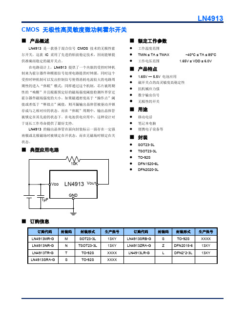
■ 产品概述
LN4913 是一款基于混合信号 CMOS 技术的无极性霍 尔开关,这款 IC 采用了先进的斩波稳定技术,因而能够提 供准确而稳定的磁开关点。
在电路设计上,LN4913 提供了一个内嵌的受控时钟机 制来为霍尔器件和模拟信号处理电路提供时钟源,同时这个 受控时钟机制可以发出控制信号使得消耗电流较大的电路周 期性的进入“休眠”模式;同样通过这个机制,芯片被周期 性的“唤醒”并且根据预定好的磁场强度阈值检测外界穿过 霍尔器件磁场强度的大小。如果磁通密度高于“操作点”阈 值或者低于“释放点”阈值,则开漏输出晶体管被驱动并锁 存成与之相对应的状态。而在“休眠”周期中,输出晶体管 被锁定在其先前的状态下。在电池供电应用中,这种设计对 于延长工作寿命提供了最好支持。
NCP1015AP100G;NCP1015AP065G;NCP1015ST100T3G;NCP1015ST65T3G;中文规格书,Datasheet资料

1
8
2
7
3
4
5
GND Figure 1. Typical Application Example
PIN FUNCTION DESCRIPTION
Pin No.
SOT−223
PDIP−7
Pin Name
1
1
VCC
−
2
NC
−
3
GND
2
4
FB
3
5
DRAIN
−
−
−
−
7
GND
4
8
GND
Function Powers the Internal Circuitry
MARKING DIAGRAMS
8 1
PDIP−7 CASE 626A AP SUFFIX
P1015APyy AWL
YYWWG
1
4
4
SOT−223
CASE 318E
1
ST SUFFIX
AYW 1015y G
G
1
yy y A WL YY WW G or G
= 06 (65 kHz), 10 (100 kHz) = A (65 kHz), B (100 kHz) = Assembly Location = Wafer Lot = Year = Work Week = Pb−Free Package
1
Publication Order Number:
NCP1015/D
NCP1015
Indicative Maximum Output Power from NCP1015
RDS(on) − Ip
230 Vac
FPGA可编程逻辑器件芯片EP3C25E144C8N中文规格书
Stratix II Device Handbook, Volume 1
DC & Switching Characteristics Stratix II Device Handbook, Volume 1
DC & Switching Characteristics
Table 5–75. Stratix II I/O Output Delay for Column Pins (Part 5 of 8)
I/O Standard
Drive Strength
Parameter
Differential
8 mA
tO P
SSTL-2 Class I
tD I P
12 mA tO P
tD I P
Differential
16 mA tO P
SSTL-2 Class II
tD I P
20 mA tO P
tD I P
(1)
tD I P
4 mA
tO P
tD I P
6 mA
tO P
tD I P
8 mA
tO P
tD I P
10 mA tO P
tD I P
12 mA tO P
(1)
tD I P
16 mA tO P
tD I P
18 mA tO P
tD I P
20 mA tO P
(1)
tD I P
tO P
tD I P
tO P
In both cases, these calculations should only be used as an estimation of power, not as a specification.
CC254x蓝牙模块规格书
捷 帆 科 技CC2540/1 蓝牙模块 规 格 书捷 帆 科 技1. 产品描述:※ ※ ※ ※ ※ ※ ※ ※ ※ 蓝牙 V4.0 版本规范; 功率级别 II 级; 超低功耗,微安级工作电流 超低电压供电,可使用 3V 钮扣电池 内置 256K 字节可擦除存储器 多种引出接口:PIO/UART/SPI/USB 监视时钟功能 极小的表面贴片封装:21.0 mm x 13.0 mm x 2.0mm RoHS 无铅生产工艺2. 应用领域:※ ※ ※ ※ ※ ※ ※ ※ 健身器材设备,如跑步机,健身器等 医疗器械设备,如脉博测量计,心率计等 家用休闲设备,如遥控器,玩具等 办公用品设备,如打印机,扫描仪等 商业设备,如收银机,二维码扫描器等 手机外设配件,如手机防丢器等 汽车设备,如汽车维修仪等 其它人机交互设备捷 帆 科 技3. 性能特点工作频段 蓝牙硬件版本 功率等级 主芯片 发射功率 接收灵敏度 天线 供电电压 尺寸 等级 2.402GHz - 2.480GHz V4.0 蓝牙 II 级 CC2540 0dBm (典型) -88dB (典型),-94(最大) 已板载天线,无需外置 2.0V-3.6V 21mm(长) * 13mm(宽) * 2.0 mm(高) 工业级 ISM 频段4. 内部原理框图捷 帆 科 技5. 电气特征5.1 极限参数 参数 储存温度 工作温度 工作电压(VDD) 输入输出接口电压 5.2 推荐操作条件 参数 储存温度 工作温度 供应电压(VDD) 输入输出接口电压 最小 -30℃ -30℃ 2.0V 0V 典型 +20℃ +20℃ 3.0V 3.0V 最大 +115℃ +75℃ 3.6V 3.6V 备注 最低 -40℃ -40℃ 2.0 V -0.3V 最高 +125℃ +85℃ +3.6V VDD+0.3V捷 帆 科 技6. 引脚布局及定义6.1 顶部引脚视图6.2 引脚定义引脚序号1 2 3 4 5 6 7 8 9 10 11 12 13 14 15 16 17引脚名称VCC GND nRST P2.2/DC P2.1/DD P2.0 P1.7 P1.6 USB_D+/SCL USB_D-/SDA P1.5 P1.4 P1.3 P1.2 P1.1 P1.0 P0.7 电源地 复位输入引脚功能说明电源引脚,接 3.3V 或纽扣电池正极数字可编程输入/输出引脚或 C2 编程时钟引脚 数字可编程输入/输出引脚或 C2 编程数据引脚 数字可编程输入/输出引脚 数字可编程输入/输出引脚 数字可编程输入/输出引脚 CC2540:USB 接口差分引脚 D+ Cc2541:I2C 接口时钟线 SCL USB 接口差分引脚 DCC2541:I2C 接口数据线 SDA 数字可编程输入/输出引脚 数字可编程输入/输出引脚 数字可编程输入/输出引脚 数字可编程输入/输出引脚 数字可编程输入/输出引脚 数字可编程输入/输出引脚,状态 LED 指示灯 数字可编程输入/输出引脚捷 帆 科 技18 19 20 21 22 23 24 P0.6 P0.5 P0.4 P0.3 P0.2 P0.1 P0.0 数字可编程输入/输出引脚 数字可编程输入/输出引脚 数字可编程输入/输出引脚 数字可编程输入/输出引脚,串口发送引脚 TX 数字可编程输入/输出引脚,串口接收引脚 RX 数字可编程输入/输出引脚 数字可编程输入/输出引脚【注】:红色部分代表蓝牙串口透传时的功能,其他引脚在串口透传时未使用7. 机械尺寸捷 帆 科 技捷 帆 科 技8. 外围原理参考9、PCB-layout 注意事项蓝牙工作在2.4G 无线频段,应尽量避免各种因素对无线收发的影响,PCB 布线时请注意以下几点: 1、包围蓝牙模块的产品外壳避免使用金属,当使用部分金属外壳时,应尽 量让模块天线部分远离金属部分。
FPGA可编程逻辑器件芯片EP3C25E144I7N中文规格书
Software Support for UFM Block4.An 8-bit data is transmitted through SI .5.nCS is pulled back to high to indicate the end of transmission.Figure 9–29 shows the WRITE operation sequence for Base mode.SECTOR-ERASESECTOR-ERASE is the instruction of erasing one sector of the UFM block. Each sector contains 256 words. WEN bit and the sector must not be protected for SE operation to be successful. nCS must be driven high before the instruction is executed internally. You may poll the nRDY bit in the software status register for the completion of the internal self-timed SECTOR-ERASE cycle. For SPI Extended mode, the SE operation is performed in the following sequence, as shown in Figure 9–30:1.nCS is pulled low.2.Opcode 00100000 is transmitted into the interface.3.The 16-bit address is sent. The eighth bit (the first seven bits will be discarded) of the address indicates which sector is erased; a 0 means sector 0 (UFM0) is erased,and a 1 means sector 1 (UFM1) is erased.Figure 9–28.WRITE Operation Sequence for Extended ModenCSSCKSISOFigure 9–29.WRITE Operation Sequence for Base ModenCSSCKSISOCreating Memory Content FileMemory Initialization for the altufm_parallel MegafunctionFor the parallel interface, if a HEX file is used to initialize the memory content for the altufm megafunction, you have to fully specify all 16 bits in each memory address, regardless of the data width selected. If your data width is less than 16 bits wide, your data must be placed in the MSBs of the data word and the remaining LSBs must be padded with 1’s.For an example, if address _width = 3 and data _width = 8 are selected for the altufm_parallel megafunction, the HEX file should contain eight addresses of data (23 addresses), each word containing 16bits. If the initial content at the location 000 is intended to be 10101010, you should specify 1010101011111111 for address 000 in the HEX file.1This specification applies only to HEX files used with the parallel interface. MIFs do not require you to fully specify 16 bits for each data word. However, both MIF and HEX files require you to specify all addresses of data according to the address _width selected in the megafunction.Memory Initialization for the altufm_spi MegafunctionThe same 16-bit data padding mentioned for altufm_parallel is required for HEX files used with the SPI Base (8 bits) and Extended (16 bits) mode interface. In addition, for SPI Base and Extended mode, you must fully specify memory content for all512addresses (both sector 0 and sector 1) in the HEX file and MIF, even if sector 1 is not used. You can put valid data for SPI Base mode addresses 0to 255 (sector 0), and initialize sector 1 to all ones.Figure 9–48.Page 4 of the altufm MegafunctionChapter 9:Using User Flash Memory in MAX II DevicesCreating Memory Content FileMemory Initialization for the altufm_i2c MegafunctionThe MAX II UFM physical memory block contains a 16-bit wide and 512deep (9-bitaddress) array. The altufm_i2c megafunction uses the following smaller array sizes:■An 8-bit wide and 128 deep (7-bit address) mapping for 1 Kbit memory size■An 8-bit wide and 256 deep (8-bit address) mapping for 2 Kbits memory size■An 8-bit wide and 512 deep (9-bit address) mapping for 4 Kbits memory size■An 8-bit wide and 1,024 deep (10-bit address) mapping for 8 Kbits memory sizeAltera recommends that you pad the MIF or HEX file for both address and data widthto fill the physical memory map for the UFM block and ensure the MIF/HEX filerepresents a full 16-bit word size and a 9-bit address space.Memory Map for 1-Kbit Memory InitializationFigure9–49 shows the memory map initialization for the altufm_i2c megafunction of1-Kbit memory size. The altufm_i2c megafunction byte address location of 00h to3Fh is mapped to the UFM block address location of 000h to 03Fh. The altufm_i2cmegafunction byte address location of 40h to 7Fh is mapped to the UFM blockaddress location of 1C0h to 1FFh. Altera recommends that you pad the unusedaddress locations of the UFM block with all ones.Figure9–49.Memory Map for 1-Kbit Memory InitializationMIF or HEX File Contents – to representthe actual data and address size for the UFM blockMemory Map for 2-Kbit Memory InitializationFigure9–50 shows the memory map initialization for the altufm_i2c megafunction of2 Kbits of memory. The altufm_i2c megafunction byte address location of 00h to 7Fhis mapped to the UFM block address location of 000h to 07Fh. The altufm_i2cmegafunction byte address location of 80h to FFh is mapped to the UFM blockaddress location of 180h to 1FFh. Altera recommends that you pad the unusedaddress location of the UFM block with all ones.Chapter 12:Real-Time ISP and ISP Clamp for MAX II DevicesDocument Revision HistoryChapter 13:IEEE 1149.1 (JTAG) Boundary-Scan Testing for MAX II DevicesIEEE Std. 1149.1 BST Operation Control。
LN2543规格书(最新完整版)
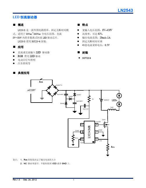
IN4007
10uF/16V
HER207 LEDs
5mH
TOFFRoscΒιβλιοθήκη VIN654
LN2543MR
1
2
3
2N60 GATE
GND
CS
Rcs
备注: 1、Rcs 的取值决定了输出电流的大小 2、NC 脚必须悬空,不能短接到 VDD 或者 GND 上。
Rev.1.0 —Sep. 24, 2012
1
■ 订购信息
悬空脚。不能短接到VIN或者GND
Rev.1.0 —Sep. 24, 2012
2
■ 功能框图
VIN
LDO
Internal supply VDD
VREF Vref_cs
S
Q
RQ
OSC
Driver
LN2543
TOFF GATE
CS
GND
■ 最大极限参数
Parameter VIN脚到接地电压 CS, TOFF, 脚到地电压 GATE管脚到地电压 VIN脚输入电流范围 存储温度范围 工作结温 ESD HBM模式
LN2543 ①②
项目
符号
① M
②
R
L
■ 管脚描述和打印标致
SOT23-6 (Top View)
VIN TOFF NC
6
5
4
封装形式 SOT23-6 卷盘编带 正向 反向
描述
LN2543
MARKING
43BX
1
2
3
CS GND GATE
43----LN2543MR
B-----die code X-----process code
LN2543
EP3C25Q240C8中文资料(Altera)中文数据手册「EasyDatasheet - 矽搜」

—
1.71 1.8 1.89
V
—
1.425 1.5 1.575 V
电源电压为输出缓冲器,1.2-V
手术
—
1.14 1.2 1.26
V
VCCA (3)
VCCD_PLL (3) VI VO
供应(模拟)电压PLL
调节器
供应(数字)电压PLL
输入电压 输出电压
TJ
工作结温
tRAMP IDiode
电源斜坡时间
电源电压为输出缓冲器,3.3-V
手术
—
1.15 1.2 1.25
V
—
3.135 3.3 3.465 V
电源电压为输出缓冲器,3.0-V
手术
—
2.85
3
3.15
V
VCCIO (3), (4)
电源电压为输出缓冲器,2.5-V
手术
电源电压为输出缓冲器,1.8-V
手术
电源电压为输出缓冲器,1.5-V
手术
—
2.375 2.5 2.625 V
直流电流幅度
当启用PCI-钳位二极管
—
— — —
对于商业用途 工业用 对于扩展温度 对于汽车使用 标准上电复位
(POR) (5) 快速POR (6)
—
2.375 2.5 2.625 V
1.15 1.2 1.25
V
–0.5 —
3.6
V
0
—
VCCIO
V
0
—
85
°C
–40 — 100 °C
–40 — 125 °C
表1-4 列出I / O引脚泄漏 目前Cyclone III器件.
f
有关功耗估算工具更多信息 ,请参
扬润HY-254103 V6 蓝牙模块硬件规格书说明书

密级:公开资料HY-254103V6硬件规格书文档版本:V1.12020年8月19日深圳市昇润科技有限公司版权所有昇润科技对本手册中可能出现的错误不承担责任。
此外,昇润科技保留随时更改硬件,软件和/或规格书的权利,恕不另行通知,并不承诺更新此处所包含的信息。
昇润的产品不被授权用作生命支持设备或系统中的关键组件。
以及不承担各种专利或知识产权的授权使用;蓝牙商目录1.概述 (4)1.1.BLE应用领域 (4)1.2.功能特点 (4)1.3.主要功能特点 (5)2.硬件规格 (7)2.1模组参数 (7)2.2.模组脚位及尺寸 (7)名称:HY-254103V6 (7)2.3.引脚定义说明 (8)2.4.电气特性 (9)2.5.工作模式 (10)2.5.1.直驱模式 (10)2.5.2.桥接模式 (11)2.6.电路连接 (11)2.6.1.大模块通信接口选择 (11)2.6.2.三种通信方式连接示意图 (12)2.6.3.ADC参考电路及注意事项 (13)3.应用注意事项 (14)4.回流焊曲线建议 (15)5.联系我们 (16)1.1.BLE应用领域健身类:运动手环,计步器,运动计量(跑步,自行车,高尔夫)。
智能家居类:插座改造,遥控开关,调光调色照明,门锁,窗帘,温湿度计,智能秤,环境烟雾探测器,宠物监管健康医疗类:医疗检测/追踪(心率,血压,血氧,脉搏,体温)。
婴幼儿护理:实时体温检测,智能婴儿床,防丢失。
玩具类:互动遥控玩具,机器人,飞行器,玩具车,防丢器。
汽车电子:胎压检测、汽车自动锁、车位记录、电动车防盗器、数据采集监控。
人机界面:HID键盘、鼠标、遥控器、手柄。
安防工控类:智能充电桩、无感门禁系统、地铁轧机。
工业4.0物联网类:5G充电设备、……1.2.功能特点CC2541透传根据蓝牙角色,可分为3种版本:蓝牙主机、蓝牙从机、蓝牙主从一体。
蓝牙主机支持SBL升级(UART升级),蓝牙从机支持OAD升级,蓝牙主从一体支持蓝牙角色切换。
KF8TS2508 2510 2514 数据手册 V1.6 芯旺微电子说明书
KF8TS2508/2510/2514数据手册V1.68位微控制器KF8TS2508/10/14数据手册KF8TS2508/2510/2514数据手册V1.6芯旺微电子 - 2/156 -产品订购信息芯片型号订货号封装FLASHRAM(Byte)内部HFOSC(Hz)外部HF/LFOSC(Hz)8位定时器16位定时器8位PWM12位ADC触摸按键I2C内部参考电压工作电压(V)KF8TS2508 KF8TS2508SD SOIC-14 4Kx16 40016M16M/ 32.768k13288 1 2V/3V/4V 2.6~5.5 KF8TS2510KF8TS2510SE SOIC-16 1010KF8TS2514KF8TS2514SG SOIC-20 1414KF8TS2514OG SSOP-20 KF8TS2514NG QFN-20版权所有@上海芯旺微电子有限公司 本文档为上海芯旺微电子有限公司在现有数据资料基础上慎重且力求准确无误编制而成.确保应用符合技术规范,是您自身应负的责任。
上海芯旺微电子有限公司不作任何明示或暗示、书面或口头、法定或其他形式的声明或担保,包括但不限于针对其使用情况、质量、性能、适销性或特定用途的适用性的声明或担保。
上海芯旺微电子有限公司对因这些信息及使用这些信息而引起的后果不承担任何责任。
如果将芯旺微电子有限公司的芯片用于生命维持和或生命安全应用,一切风险由使用方自负。
使用方同意在由此引发任何一切伤害、索赔、诉讼或费用时,会维护和保障上海芯旺微电子有限公司免于承担法律责任,并加以赔偿。
本文档中所述的器件应用信息及其他类似内容仅为您提供便利,可能有更新的信息所替代。
上海芯旺微电子有限公司会不定期进行更新,恕不另行通知。
使用方如需获得最新的产品信息,请及时访问上海芯旺微电子有限公司官网或与上海芯旺微电子有限公司联系。
KF8TS25XX芯片使用注意事项芯片的ESD防护措施KF8TS25XX芯片提供满足工业级ESD标准保护电路。
FPGA可编程逻辑器件芯片EP4CE55F23C8LN中文规格书
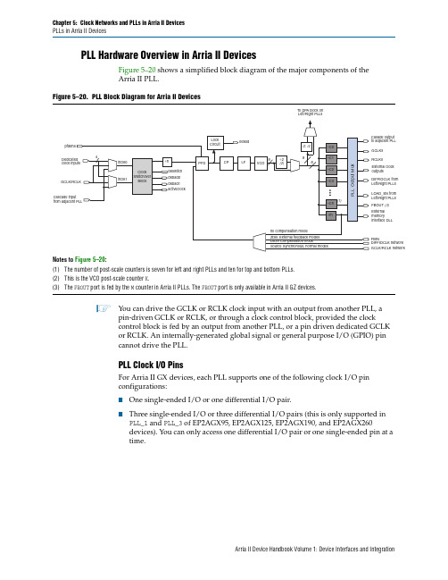
PLLs in Arria II Devices PLL Hardware Overview in Arria II DevicesFigure 5–20 shows a simplified block diagram of the major components of theArria II PLL.1You can drive the GCLK or RCLK clock input with an output from another PLL, apin-driven GCLK or RCLK, or through a clock control block, provided the clockcontrol block is fed by an output from another PLL, or a pin driven dedicated GCLK or RCLK. An internally-generated global signal or general purpose I/O (GPIO) pin cannot drive the PLL.PLL Clock I/O PinsFor Arria II GX devices, each PLL supports one of the following clock I/O pinconfigurations:■One single-ended I/O or one differential I/O pair.■Three single-ended I/O or three differential I/O pairs (this is only supported inPLL _1 and PLL _3 of EP2AGX95, EP2AGX125, EP2AGX190, and EP2AGX260devices). You can only access one differential I/O pair or one single-ended pin at a time.Figure 5–20.PLL Block Diagram for Arria II DevicesNotes to Figure 5–20:(1)The number of post-scale counters is seven for left and right PLLs and ten for top and bottom PLLs.(2)This is the VCO post-scale counter K .(3)The FBOUT port is fed by the M counter in Arria II PLLs. The FBOUT port is only available in Arria II GZ devices.Table5–11.RCLK Outputs From the PLL Clock Outputs for Arria II GZ Device(Part 2 of 2)PLL NumberClock ResourceL2L3B1B2R2R3T1T2 RCLK[32..43]————v v——RCLK[44..63]——————v vClock Control BlockEvery GCLK and RCLK network has its own clock control block. The control blockprovides the following features:■Clock source selection (dynamic selection for GCLKs)■GCLK multiplexing■Clock power down (static or dynamic clock enable or disable)Figure5–12 shows the GCLK select blocks for Arria II devices.Figure5–12.GCLK Control Block for Arria II DevicesNotes to Figure5–12:(1)You can only dynamically control these clock select signals through internal logic when the device is operating in usermode.(2)These clock select signals can only be set through a configuration file (.sof or .pof) and cannot be dynamicallycontrolled during user mode operation.(3)The left side of the Arria II GX device only allows PLL counter outputs as the dynamic clock source selection to theGCLK network.(4)This is only available on the left side of the Arria II GX device.Select the clock source for the GCLK control block either statically with a setting in theQuartus II software or dynamically with an internal logic to drive the multiplexerselect inputs. When selecting the clock source dynamically, you can either select twoPLL outputs (such as C0 or C1), or a combination of clock pins or PLL outputs.Figure5–6.PCLK Networks in (EP2AGX95 and EP2AGX125 Devices)Figure5–7.PCLK Networks in (EP2AGX190 and EP2AGX260 Devices)。
DIN标准中文版

Plastics - Methods of test for the determination of the effects of immersion in liquid chemicals cables of rated voltages up to and including 450 750 V and having cross linked insulation Part 7 cables with increased heat resistance for internal wiring for a conductor temperature of 11 C
DIN 53163-1988
铜导线用冲压电缆接头 纸和纸板的试验 不透明度的测定 纸的检测 透明度的测定
颜料及填充剂的测试 填充剂粉末以及白色颜 料粉末亮造革的检验 拉伸试验
DIN 53357-1982 塑料布和塑料薄膜的检验 层间分离试验
DIN 53363-2003 DIN 53453-1975 DIN 53512-2000 DIN 53754-1997
铁路车辆及车辆部件焊接.第1部分:基本术 语,基本规则
由X射线胶片、增强箔和X射线片匣构成的医 学X射线诊断用图像记录系统调制传递函数的 测定
DIN 1552-1-1987 轨道车辆用轴套.钢制压配合轴套
DIN 1552-2-1987 轨道车辆用轴套.钢制压配合轴套
TLC2543中文资料_数据手册_参数

万联芯城专注电子元器件配单服务,只售原装现货库存,万联芯城 电子元器件全国供应,专为终端生产,研发企业提供现货物料, 价格优势明显,BOM配单整单采购可享优惠价,提交BOM表报价 ,最快可当天发货,万联芯城电子元器件配单服务可以为客户节 省采购成本,满足客户物料需求,丰富的电子元器件供应链体系 已为全国多家终端企业服务,点击进入万联芯城。
合格的汽车ApplicationsD 12位分辨率A / D ConverterD 10-µs转换时间在OperatingTemperatureD 11模拟输入ChannelsD三内建自测ModesD固 有取样保持的FunctionD线性误差。±1 LSB MaxD片上TLC2543系统ClockD转换末尾OutputD单极或双极输出操作(签署二进制对1/2 theApplied参考电压)D可编程MSB和LSB FirstD可编程电源DownD可编程输出数据LengthD CMOS TechnologyD申请报告可用‡ descriptionThe TLC2543 12位,开关电容,逐次逼近,数模转换器。每台设备有三个控制输入(芯片选择(CS)、输入-输出时钟和地址输入(数据 输入)),通过串行三态输出与主机处理器或外围设备的串口通信。该设备允许从主机高速传输数据。除了高速转换器和多用途控制能 力,该设备还有一个芯片上的14通道多路复用器,可以选择11个输入中的任意一个或3个内部自检电压中的任意一个。这个功能是自动 的。在转换结束时,转换结束(EOC)输出变高,表示转换已经完成。TLC2543集成在器件中的转换器具有不同的高阻抗参考输入,便于 比值转换、缩放和模拟电路与逻辑和电源噪声隔离。开关电容设计允许在整个工作温度范围内的低误差转换。订货信息工作原理首先, 芯片选择(CS)高,I/O时钟和数据输入被禁用,TLC2543数据输出处于高阻抗状态。CS低电平通过启用I/O时钟和数据输入开始转换序 列,并从高阻抗状态中删除数据。输入数据为8位数据流,包括4位模拟信道地址(D7−D4)、2位数据纵向选择(D3−D2)、输出MSB或LSB 第一个位(D1)和应用于数据输入的单极或双极输出选择位(D0)。TLC2543应用于I/O时钟终端的I/O时钟序列将此数据传输到输入数据寄 存器。在这个传输过程中,I/O时钟序列还将之前的转换结果从输出数据寄存器转移到数据输出。I/O时钟接收8、12或16个时钟周期长 的输入序列,这取决于输入数据寄存器中的数据长度选择。TLC2543模拟输入的采样从输入I/O时钟序列的第四个下降沿开始,并在I/O 时钟序列的最后一个下降沿之后进行。I/O时钟序列的最后一个下降沿也将EOC降低并开始转换。转换器的操作转换器的操作被组织成 两个不同的周期的序列:1)I/O周期和2)实际的转换周期。I/O周期I/O周期由外部提供的I/O时钟定义,持续8、12或16个时钟周期,取决于 所选输出数据的长度。在I/O周期中,同时执行以下两个操作。一个由地址和控制信息组成的8位数据流被提供给数据输入。这些数据被 转移到前八个I/O时钟上升边缘的设备中。在12或16个时钟的I/O传输过程中,第一个时钟后的数据输入将被忽略。数据输出(长度为 8、12或16位)是在数据输出时串行提供的。当CS值较低时,第一个输出数据位出现在EOC上升沿。当CS在两次转换之间被否定时,第 一个outputdata位出现在CS的下降边缘。该数据是前一个转换周期的结果,在第一个输出数据位之后,每个后续的位都被锁定在每个后 续I/O时钟的下降边缘。转换周期转换周期对用户是透明的,它由一个内部时钟同步toI/O时钟控制。在转换期间,该装置对模拟输入电 压进行逐次近似转换。EOC输出在转换周期开始时较低,在转换完成并锁定输出数据寄存器时较高。转换周期只有在I/Ocycle完成后才 开始,这样可以将外部数字噪声对转换精度的影响降到最低。
CC2541中文数据手册
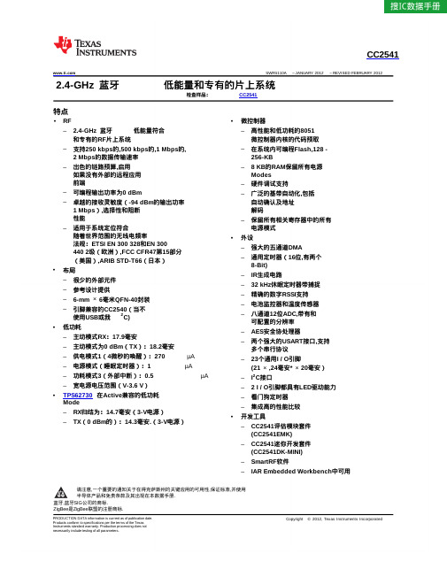
VDD (2 V–3.6 V) DCOUPL
SFR bus
SLEEP TIMER
HIGH SPEED RC-OSC
32-kHz RC-OSC
POWER MGT. CONTROLLER
8051 CPU CORE
DMA
PDATA XRAM IRAM
SFR
UNIFIED
true
为片上系统(SoC)解决方案
蓝牙
low
能源和专有的2.4-GHz应用.它使建立强大的网络节点
,同时降低总体材料清单成本. CC2541结合了领先的
RF收发器,业界标准的增强型8051 MCU,性能优良的系统内可 编程闪存,8 KB RAM和许多其他强大的支持功能和外设
. CC2541是非常适合需要超低功耗的系统.这是指
ADC,转换时
MIN TYP MAX单位 17.9
20.2 mA
16.8
18.2
270
1
µA
0.5
6.7
mA
90
90
60
μA
70
0.6
1.2
mA
4
提交文档反馈
产品文件夹链接(s): CC2541
Copyright © 2012, Texas Instruments Incorporated
CC2541
1Mbps的GFSK,250 kHz的偏差,
蓝牙
A = 25°C和VDD = 3 V, 低能量模式,和0.1%BER
参数
测试条件
RX模式,标准模式,没有外设活跃,低MCU 活动
高增益模式下,RX模式,没有外设活跃,低MCU 活动
TLC2543资料c语言

2.2TLC2543的内部寄存器
从编程角度看,TLC2543内部寄存器有输入数据寄存器与输出数据寄存器。输入数据寄存器存放从DATA INPUT端移入的控制字。输出数据寄存器存放转换好的数据,以供从DATA OUT端移出。
(4)控制字输入引脚
DATA TNPUT,17脚:控制字输入端,选择通道及输出数据格式的控制字由此输入。
(5)转换数据输出引脚
DATA OUT,16脚:A/D转换结果输出的3态串行输出端。
2TLC2543的编程要点
2.1控制字的格式
控制字为从DATA INPUT端串行输入TLC2543芯片内部的8位数据,它告诉TLC2543要转换的模拟量通道、转换后的输出数据长度、输出数据的格式。其中高4位(D7~D4)决定通道号,对于0通道至10通道,该4位分别为0000、0001、…、1010,该4位为其它数字时的功能,用于检测校正,本文不作具体介绍。低4位决定输出数据长度及格式,其中D3、D2决定输出数据长度,TLC2543的输出数据长度有8位、12位、16位,但由于TLC2543为12位A/D转换芯片,经过分析可以看出,8位、16位输出对TLC2543的应用意义不大,宜定在12位输出,D3、D2两位为00即可。D1决定输出数据是高位先送出,还是低位先送出,若为高位先送出,该位为0,反之为1。D0决定输出数据是单极性(二进制)还是双极性(2的补码),若为单极性,该位为0,反之为1。
关键词:A/D转换;TLC2543芯片;51系列单片机;接口技术
中图法分类号:TP334.7文献识别码:B
LG LSNB2541AT 空调 说明书

安装手册空调·请先详细阅读本说明手册后再进行产品安装。
·安装作业必须符合国家布线标准并由授权人员进行。
·阅读完毕后,请妥善保管本安装手册,以供日后参考。
挂型类型 :壁P/NO : MFL67001203/cn2空调安装注意事项 (3)简介.............................6手册使用符号说明 .............6安装 ........................... 7安装零件......................7安装工具......................7安装图示......................8选择最佳安装地点.............9固定安装座....................10墙上钻孔......................10扩管作业 ......................11管路连接......................12配线 ..........................18检查排水系统..................20管路架设......................21排气...........................22运转测试......................24临海安装指南..................26管路长度与高度. (27)[A]类螺丝数枚连接线安装指南图示管路:排气管路排水管路绝缘材料其他排水管(外径...................15.5mm) [B]类螺丝数枚 [C]类螺丝数枚水平仪表螺丝起子电钻钻孔机(ø70mm)水平仪扩管工具组特定规格扭力扳手1.8kg.m, 4.2kg.m, 5.5kg.m,6.6kg.m(依照型号使用不同扳手)扳手.................单接头用一杯水六角扳手(4mm)气体探测仪r 真空泵歧管仪表使用手册温度计遥控器专用座安装需求必备零件必备工具安装注意事项为避免人员受伤与财产损失,请务必遵守以下说明事项。
LN2547规格书(最新版)
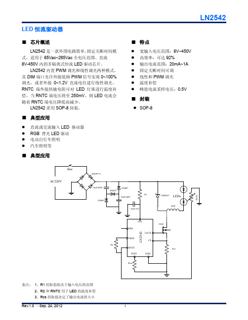
LED恒流驱动器
■芯片概述
LN2542是一款外围电路简单,固定关断时间模式,适用于85Vac~265Vac全电压范围、直流
8V-450V内的非隔离式恒流LED驱动芯片。
LN2542内置PWM调光和线性调光两种模式,其DIM端口允许外接低频PWM信号实现0~100%调光,或者外接0~1.2V直流电位进行线性调光。
RNTC端外接热敏电阻可对LED灯珠进行温度补偿,当RNTC端电压将至250mV,则LED电流会随着RNTC端电压降低而减少。
LN2542采用SOP-8封装。
■典型应用
●直流或交流输入LED 驱动器
●RGB 背光LED驱动
●电动自行车照明
●汽车照明等■特点
●宽输入电压范围:8V~450V ●高效率:可达92%
●输出电流范围:20mA~1A ●固定关断时间可调
●线性和PWM调光
●温度补偿
●峰值电流采样电压:0.5V ■封装
●SOP-8
■典型应用
备注:1、R1的取值取决于输入电压的范围
2、R2和RNTC用于LED的温度补偿
■ 订购信息
■ 管脚示意图和功能
12345
67
8VREF DIM
RNTC GND GATE
CS
TOFF
VIN
SOP-8(TOP VIEW)
■ 功能框图
TOFF
GATE
CS
VIN VREF
RNTC
DIM
■ 最大极限参数
SOP-8
SOP-8。
- 1、下载文档前请自行甄别文档内容的完整性,平台不提供额外的编辑、内容补充、找答案等附加服务。
- 2、"仅部分预览"的文档,不可在线预览部分如存在完整性等问题,可反馈申请退款(可完整预览的文档不适用该条件!)。
- 3、如文档侵犯您的权益,请联系客服反馈,我们会尽快为您处理(人工客服工作时间:9:00-18:30)。
管脚
2 3 1
5
6 4
管脚名
GND GATE
CS
TOFF
VIN NC
功能
接地。 外接高压NMOSFET的栅极驱动管脚。 电流取样端,通过外接电阻到地来设置芯片的输出电流。 在该管脚和GND之间接一电阻来设置MOSFET的关断时间,最小关断时间可 达510ns, 通过外接一个电阻连到最高100V直流电源上,必须接一个旁路电容。
LED 恒流驱动器
■ 概述
LN2543 是一款外围电路简单,固定关断时间模 式,适用于 85Vac~265Vac 全电压范围、直流 8V-450V 内的非隔离式恒流 LED 驱动芯片。
LN2543 采用 SOT23-6 封装。
■ 应用
直流或交流输入 LED 驱动器 RGB 背光 LED 驱动 电动自行车照明 汽车照明等
VGATE IVIN TSTG TJ
Maximum Rating -0.3—14 -0.3—6 -0.3—12 1—20 -40—150 -40—150 4000
Unit V V V mA ℃ ℃ V
Conditions
VIN=10.5V GATE floating
VIN rising VIN falling
LN2543 ①②
项目
符号
① M
②
R
L
■ 管脚描述和打印标致
SOT23-6 (Top View)
VIN TOFF NC
6
5
4
封装形式 SOT23-6 卷盘编带 正向 反向
描述
LN2543
MARKING
43BX
1
2
3
CS GND GATE
43----LN2543MR
B-----die code X-----process code
IN4007
10uF/16V
HER207 LEDs
5mH
TOFF
Rosc VIN
6
5
4
LN2543MR
1
2
3
2N60 GATE
GND
CS
Rcs
备注: 1、Rcs 的取值决定了输出电流的大小 2、NC 脚必须悬空,不能短接到 VDD 或者 GND 上。
Rev.1.0 —Sep. 24, 2012
1
■ 订购信息
LN2543
■ 特点
宽输入电压范围:8V~450V 高效率:可达 92% 输出电流范围:20mA~1A 固定关断时间可调 峰值电流采样电压:0.5V
■ 封装
SOT23-6
■ 典型应用
fuse AC220V
IN4007*4
10uF/400V
IN4007
IN4007
R1 10uF/400V
■ 电参数
Symbol VINDC
VIN_clamp
IIN
UVLO △ UVLO
VCSTH TOFF
Parameter
输入直流电压范围 VIN 钳位电压
静态工作电流
VIN 欠压保护电压 欠压保护迟滞电压 电流取样端 CS 阈值电压 关断时间
Rev.1.0 —Sep. 24, 2012
Symbol Vin
悬空脚。不能短接到VIN或者GND
Rev.1.0 —Sep. 24, 2012
2
■ 功能框图
VIN
LDO
Internal supply VDD
VREF Vref_cs
S
Q
RQ
OSC
Driver
LN2543
TOFF GATE
CS
GND
■ 最大极限参数
Parameter VIN脚到接地电压 CS, TOFF, 脚到地电压 GATE管脚到地电压 VIN脚输入电流范围 存储温度范围 工作结温 ESD HBM模式
Min. 8 6.0
TOFF pin Floating
Typ. 6.5
Max. Unit 450 V 7.0
0.4
1
mA
5.5
V
700
mV
500
mV
510
ns
3
■ Package Information
SOT23-6
LN2543
Rev.1.0 —Sep. 24, 2012
4
■ Package Information
SOT23-6
LN2543
Rev.1.0 —Sep. 24, 2012
4
