AM27S19175JC-S中文资料
Inspiron 27 7000 服务手册说明书

Inspiron 27 7000服务手册计算机型号: Inspiron 27-7775管制型号: W16C管制类型: W16C001注、小心和警告注: “注”表示帮助您更好地使用该产品的重要信息。
小心: “小心”表示可能会损坏硬件或导致数据丢失,并说明如何避免此类问题。
警告: “警告”表示可能会造成财产损失、人身伤害甚至死亡。
版权所有© 2017 Dell Inc. 或其附属公司。
保留所有权利。
Dell、EMC 和其他商标均为 Dell Inc. 或其附属公司的商标。
其他商标均为其各自所有者的商标。
2017 - 05Rev. A00目录拆装计算机内部组件之前 (11)开始之前 (11)安全说明 (11)建议工具 (12)螺钉列表 (12)拆装计算机内部组件之后 (15)技术概览 (16)计算机内部视图 (16)系统板组件 (17)卸下后盖 (19)步骤 (19)装回后盖 (20)步骤 (20)卸下支架 (21)前提条件 (21)步骤 (21)装回支架 (23)步骤 (23)完成条件 (23)3卸下硬盘驱动器。
(24)前提条件 (24)步骤 (24)装回硬盘驱动器 (27)步骤 (27)完成条件 (27)卸下内框架 (28)前提条件 (28)步骤 (29)装回内框架 (32)步骤 (32)完成条件 (32)卸下摄像头 (33)前提条件 (33)步骤 (33)装回摄像头 (35)步骤 (35)完成条件 (35)卸下麦克风 (36)前提条件 (36)步骤 (36)装回麦克风 (38)步骤 (38)完成条件 (38)4卸下电源按钮板 (39)前提条件 (39)步骤 (39)装回电源按钮板 (41)步骤 (41)完成条件 (41)卸下前挡板 (42)前提条件 (42)步骤 (43)装回前挡板 (45)步骤 (45)完成条件 (45)卸下介质卡读取器 (46)前提条件 (46)步骤 (46)装回介质卡读取器 (50)步骤 (50)完成条件 (50)卸下侧面 I/O 板 (51)前提条件 (51)步骤 (51)装回侧面 I/O 板 (53)步骤 (53)完成条件 (53)5卸下系统板护罩 (54)前提条件 (54)步骤 (54)装回系统板护罩 (56)步骤 (56)完成条件 (56)卸下风扇 (57)前提条件 (57)步骤 (57)装回风扇 (59)步骤 (59)完成条件 (59)卸下扬声器 (60)前提条件 (60)步骤 (60)装回扬声器 (62)步骤 (62)完成条件 (62)卸下次低音扬声器 (63)前提条件 (63)步骤 (63)装回次低音扬声器 (65)步骤 (65)完成条件 (65)6取出币形电池 (66)前提条件 (66)步骤 (66)装回币形电池 (68)步骤 (68)完成条件 (68)卸下内存模块 (69)前提条件 (69)步骤 (70)装回内存模块 (71)步骤 (71)完成条件 (71)卸下固态驱动器 (72)前提条件 (72)步骤 (73)装回固态驱动器 (74)步骤 (74)完成条件 (74)卸下无线网卡 (75)前提条件 (75)步骤 (76)装回无线网卡 (78)步骤 (78)完成条件 (79)7卸下散热器 (80)前提条件 (80)步骤 (80)装回散热器 (82)步骤 (82)完成条件 (82)卸下处理器 (83)前提条件 (83)步骤 (84)装回处理器 (85)步骤 (85)完成条件 (86)卸下 I/O 支架 (87)前提条件 (87)步骤 (87)装回 I/O 支架 (89)步骤 (89)完成条件 (89)卸下 I/O 板 (90)前提条件 (90)步骤 (90)装回 I/O 板 (94)步骤 (94)完成条件 (94)8卸下系统板 (95)前提条件 (95)步骤 (95)装回系统板 (99)步骤 (99)完成条件 (99)卸下中框 (101)前提条件 (101)步骤 (102)装回中框 (103)步骤 (103)完成条件 (106)卸下显示屏面板 (108)前提条件 (108)步骤 (108)装回显示屏面板 (112)步骤 (112)完成条件 (115)刷新 BIOS (116)BIOS 设置程序 (117)BIOS 概览 (117)进入 BIOS 设置程序 (117)系统设置选项 (117)清除已忘记的密码 (123)9前提条件 (123)步骤 (123)完成条件 (124)清除 CMOS 设置 (124)前提条件 (124)步骤 (125)完成条件 (125)诊断程序 (126)获取帮助和联系 Dell (128)自助资源 (128)联系 Dell (128)10拆装计算机内部组件之前注: 根据您所订购的配置,本文档中的图像可能与您的计算机有所差异。
MSI Modern AM271 11M Windows 10 Home 27英寸IPS显示器说明书

Be Your Window To TheWorldSelling PointsModern AM271 11MWindows 10 Home - MSI recommends Windows 11 Pro for business FREE Upgrade to Windows 11*27" IPS Grade Panel LED Backlight (1920 x 1080 FHD)Intel® Tiger Lake processors with DDR4 memory FHD Webcam includedMSI Anti-Flicker & Less Blue Light technology protect users' eyes.Instant Display Technology makes AIO become to monitor mode without system booting upMSI Storage Rapid Upgrade Design helps you to upgrade or maintain your 2.5" storageUSB 3.2 Gen 2 Type C with reversible design & USB 3.2Gen 2 Type A ports provide the best data delivery experience & support Super ChargerSilent PRO Cooling System: Server Grade Thermal Module ensures a silent and stable operation with a longer life cycle ...Picture and logosSystem I/O-Ports2x USB3.2 Gen 2 Type C 1.2x USB3.2 Gen 2 Type A2.1x Mic-in/Headphone-out combo3.1x Switchable 2.5” Storage4.5-Way Navigator5.1x DC-in6.1x Kensington Lock7.1x HDMI in8.1x HDMI out9.2x USB 2.0 Type A 10.1x RJ45 LAN11.1x USB 2.0 Type A12.SpecificationOperating Systems N/AScreen Size27" (69 cm)Active Display Area (mm)597.888(H) × 336.312(V) Curvature FlatPanel Type IPSResolution1920x1080 (FHD)Pixel pitch0.3114(H)X0.3114(V) Brightness (nits)300Contrast Ratio1000:1Signal Frequency56~84.5 KHz(H) / 50~75 Hz(V) Response Time (GTG)14msView Angles178°(H)/178°(V)Surface Treatment Anti-GlareTouch Screen Non-touchDisplay Colors16.7MMic-in NAHeadphone-out NALock type KensingtonAC Adapter Output120WBattery N/ABattery Whrs N/ACPU Number Intel Core i7-1165G7CPU Clock 2.8GHzCPU Cores4TDP28WCache12 MB Intel® Smart Cache Threads8Chipsets N/AMemory Size8GB(8GB*1)Memory Type DDR4 SDRAMMemory Speed1600(3200)MHzModule Type SO-DIMMMemory Slot(Total)2Memory Slot(Free)1Max Capacity Max 64GBSSD Interface PCIe GEN3x4 w/o DRAM NVMe SSD Form Factor M.2-2280 M-KEYSSD Config512GB*1SSD Size512GBHDD1 Interface N/AHDD1 Form Factor N/AHDD1 Size N/AHDD1 RPM N/AODD(Type)N/AODD Height N/AODD Type N/AM.2 slots(Total)1M.2 slots(Free)02.5" Drive Bays(Total)12.5" Drive Bays (Free)1LAN Realtek RTL8111HWLAN INTEL/AX201.NGWG.NVW WLAN Version802.11ax 2x2+BTBT Version 5.2Audio Chipset Realtek ALC233Audio Type 2.1 Channel HD AudioUSB 2.0 Type A NAUSB 3.2 Gen 1 Type A NAUSB 3.2 Gen 1 Type C NAUSB 3.2 Gen 2 Type A2USB 3.2 Gen 2 Type C2USB 3.2 Gen 2x2 Type C NAUSB 3.2 Gen 2x2 Type A NAMic-inHeadphone-out combo1USB 3.2 Gen 2x2 Type C (R)NAUSB 3.2 Gen 2x2 Type A (R)NAUSB 3.2 Gen 2 Type C (R)NAUSB 3.2 Gen 2 Type A (R)NAUSB 3.2 Gen 1 Type C (R)NAUSB 3.2 Gen 1 Type A (R)NAUSB 2.0 Type C (R)NAUSB 2.0 Type A (R)2RJ451Card Reader NAVGA out NAHDMI out1x (v2.0)DP out NAmini DP out NAPS2NACOM Port NADVI-D out NAHDMI in1Mic-inHeadphone-out combo (R)NAPrinter Port (Parallel)NAKeyboard Interface USBMouse Interface USBPower Cord1AC Adaptor1Warranty Card1Quick Guide2User Manual1VESA Mount kit N/AKeyboard SK9626MMouse SM9023MHeadphone-out (HiFi SPDIF)NAWebCam external webcam Operating, Storage Temperature0° C ~ 35° C ; -20° C ~ 60° C Operating, Storage Humidity0% ~ 85%;0% ~ 90% Regulatory Compliance FCC(Class B)CB/CEUL(CUL)BSMIVCCIRCM(C-Tick)Adjustment (Tilt)-5~15Adjustment (Swivel)NAAdjustment (Height)NAAdjustment (Pivot)NAProduct Dimension with Stand (WxDxH) (mm)611.75 x 169.96 x 436.06 Product Dimension with Stand (WxDxH) (inch)24.08 x 6.69 x 17.17 Weight (Net kg) 5.82Weight (Gross kg)8.6Product Dimension with Holder (WxDxH) (mm)TBD x TBD x TBDProduct Dimension with Holder (WxDxH) (inch)TBD x TBD x TBD528 x 219 x 725Inside Carton Dimension with Holder (WxDxH)(mm)20.79 x 8.62 x 28.54Inside Carton Dimension with Holder (WxDxH)(inch)19 x 20 x 28Inside Carton Dimension with Stand (WxDxH)(mm).75 x .79 x 1.1Inside Carton Dimension with Stand (WxDxH)(inch)N/AOuter Carton Dimension with Holder (WxDxH)(mm)Warranty36MColor ID1/Black-Black-BlackEAN4719072923341。
LG ACD-1000-LG27 室内旋转、俯仰、拉伸摄像头指南说明书

1 IntroductionFeatures 3Components 4System Configuration 52 RS485 and PTZ BasicsPhysical Connection 6Multiple PTZ Setup 7ID, Protocol, Baud Rate 93 InstallationCeiling Mount 104 Camera AddressingCamera Address Setting 11 Protocol and Baud Rate Settings 135 Basic FunctionsSelecting Camera14Setting Presets15Calling Presets15Clearing Presets15Auto Cruise16Auto Pan166 Advanced FunctionsCamera Power 17Back Light Compensation 17Digital Zoom 17Focus Mode 17Iris Mode 18White Balance Mode 187 On Screen DisplayMain Menu 19Focus Set 20Auto White Balance 20Auto Exposure 21Special Functions 21Motion Detection 22Function On Screen Display 228 Parts Description and Function 239 Product Specifications 24Camera Specification• Sony Module 480 Lines• 27X Optical Zoom• 10X Digital Zoom• 3.25mm – 88mm Zoom• IR Sensitive• 12V DCComplete View• 360 Degree Pan, 90 Degree Tilt. For No Blind SpotsHousing• Indoor Use Only• Multiple Mounting Configurations• Operating Temperatures: 32° to 104° FPTZ Control• RS-485 Communication, MAX 31 Multi-drop• Versatile Pelco-D and Pelco P Protocol• Variable Pan and Tilt Speed• 64 Programmable Presets• OSD Setup• Programmable Cruise SequenceParts InformationItemPart No. DescriptionDome Camera and HousingACD-1000-LG27NTSC Dome Camera, Indoor Housing, Including Transparent DomePower Supply 12v DC 2.5A Power Supply ManualManual for ACD-1000-LG27Default ComponentsDome Camera and HousingAccessoriesACD-1000 ManualPower SupplyConfigurationPart DescriptionVideo OutputBlueNet Video serverBlueNet Video serverDVR DVRPTZ Controller MonitorRS-485 Input1. Mounting Base2. Outer Tube3. Shading Cover4. Outer Cover5. Camera6. Connecting CableRS-485 communicationRS-485 communication is used to control a PTZ camera. Standalone DVRs, PC-based DVRs, keyboard joystick PTZ controllers, video servers, and a variety of other CCTV equipment usually have an RS-485 interface (push terminals, D-Sub connector, etc.) for PTZ control. The CCTV equipment transmits control signals while the PTZ camera receives the signals and performs the function required.RS-485 utilizes two wires ; a ‘+’ wire and a ‘–’ wire. These two wires may also be label or reference as:• + and – • D+ and D- • A+ and B-•RS485+ and RS485-To make the physical connection from the controlling device (DVR, keyboard controller, etc.) to the PTZ, simply connect the RS485 ‘-’ from the controlling device to the RS485 ‘-’ on the PTZ. Do the same for the RS485 ‘+’. Any type of wire can be used for the connection, but 0.56mm (24AWG) twisted pair is recommended.++-- PTZ Physical ConnectionsControllerBaud Rate is the data transmission rate in bps (bits per second). Both the controlling device and PTZ must use the same baud rate. Most PTZ camera and devices default to a baud rate of 2400 bps.The maximum theoretical transmitting distances of RS-485 are below using 0.56mm (24AWG) twisted pair cable.Baud Rate Maximum Distance2400 bps 1800m 4800 bps1200m 9600 bps800mIf thinner cables are used or the dome is installed in an environment with strong electromagnetic interference or many PTZs are used on the same line, the maximum distance will be decreased.For multiple PTZ installs , RS485 standards require a daisy-chain connection between the equipment. Up to 32 devices, including the controller can be daisy-chained. A 120 Ω termination must be made on the first and last device in the chain. Most controllers are already terminated. To terminate the last PTZ in line, simply locate the 120 Ω termination resistor jumper on the PTZ’s protocol PCB and set the jumper to pins 1 & 2. By default, the PTZ is not terminated, thus having the pins on 2 & 3. For Star Configurations, see the next page.Termination Jumper Location.Continued on Next PageMultiple PTZ (cont.)Some circumstances require the use of a star configuration. The termination resistors must be set on the two devices that are the farthest distances away from each other, in this case #1 and #15 as seen below.As the star configuration does not conform to the RS485 standards, problems such as signal reflection and lower anti-interference performance arise when the cable runs are long. In addition, the reliability of control signals are decreased which may cause the PTZ to respond intermittently, not respond at all, or operate a single command continuously without ever stopping. In these circumstances, the factory recommends the use of an RS485 distributor (DR-HB16). The distributor can change the star configuration connection to the mode of connection stipulated in the RS485 standards. With the distributor, reliable data transmission can be received.PTZ Addressing and Communication ProtocolBefore installing PTZs, you must understand 3 things:CameraID-PTZProtocol-PTZ-PTZ Baud RatePTZ Camera ID - Each PTZ camera in an install must have a unique ID number assigned. MostPTZs default to ID#1. The PTZ controller must be told what PTZ camera tocontrol, and this ID number is called to control the corresponding camera. ThePTZ ID number can be set to any number 1 – 1023.PTZ Protocol - All PTZ controllers and cameras need to support a common communicationlanguage in order to send/receive control commands. This language is called aprotocol. The protocol set in the PTZ camera must match the protocol set in thecontroller. Below is a list of commonly supported protocols.•Pelco-D•Pelco-P•Santachi•Hunda600•LongcomityPTZ Baud Rate - Baud Rate is the data transmission rate in bps (bits per second). Both the controlling device and PTZ must use the same baud rate. Most PTZ cameras anddevices default to a baud rate of 2400 bps.Ceiling Mount Installation using Indoor Housing Assembly1. Remove Mounting Base fromdome and mount to ceiling2. Remove the Outer Tube from thethree screws located on top of the Outer Tube, underneath the Mounting Base, to set DIPswitches according to Protocol, Baud rate, and Camera IDdesired. (See page 11 for details)RS-485 communicationRS-485 communication is used to control the camera. RS-485 utilizes two wires, + and -. Protocol, Baud rate and Camera Address are also required and are set using 2 sets of Dip Switch sets under the data board, accessed by removing the Outer Tube (see page 10). Each camera connected to the PTZ controller must have a unique address.• Specification Standard RS-485 with MAX. 31 Camera Control • Number of wire 2 Wire (D+, D-)• Protocol Pelco-D, Pelco-P, A01, B01, Santachi, Longcomity and HUNDA600SW 1 : Camera Address SettingsON1 2 3 4 5 6 7 8 9 10• Factory Default ID is 1• The dip switches are equivalent to 10-bit binary. Examples are listed on the next page.SW 1 : Camera Address Settings (continued)When using more than 1 RS-485 device each unit must be given a unique address. Refer to the chart on the previous page for the value of each dip switch. For each dip switch that is ON the value/values are added together, the total is the address of that unit.For Example:For an address of 1:Dip switch #1 (value = 1) will be ON all others OFFFor an address of 5:Dip switch #1 (value = 1) & #3 (value = 4) will be ON all others OFFFor an address of 157:Dip Switch #1 (value = 1), #3 (value = 4), #4 (value = 8), #5 (value = 16), #8 (value =128) will be ON all others OFFSW 2 : Camera Protocol and Baud Rate SettingsThis camera supports multiple RS-485 Protocols and Baud Rates which can be set using the SW2Dip switch located under the data board, accessed by removing the Outer Tube (see page 10).. The table below contains a list of protocols supported by the camera and the default baud rate for the protocol.Selection Of ProtocolsDefault BaudRatesSupported Protocol1st2nd 3rd 4th 5th 6th Pelco D /2400 ON ON OFF OFF OFF OFF Pelco P /4800 OFF OFF ON OFF ON OFF Pelco P /9600 OFF OFF ON OFF OFF ON A01 OFF OFF OFF OFF ON OFF B01 ON OFF OFF OFF OFF ON Santachi OFF ON OFF OFF OFFON Longcomity OFF ON ON OFF OFF ON Hunda600 ON ON ON OFF OFF ONDip Switch settings for configuring the camera to use Pelco D Protocol at 2400 Baud:Below is a table showing the proper settings of the 5th and 6th dip switch on SW2 for setting preferred baud rate to match that of the PTZ controller.Selection Of Protocols Baud RatesBaud Rate 1st2nd 3rd 4th 5th 6th2400OFF OFF 4800 ON OFF 9600 OFF ON 19200ON ONOnce initial control of the PTZ has been established by correctly connecting RS-485, setting matching protocol and baud rate in the PTZ and controller, and the user is able to pan, tilt, and zoom additional features can be utilized.All Basic Functions such as setting presets, calling presets, clearing presets, enabling auto cruise (tour), setting auto pan, enable auto pan are listed in this section. Any PTZ controlling device can enable these functions IF the controlling device supports at least 64 presets. Examples have been given below for operation using the KCT-100 and KCT-2500 keyboard joystick controllers.*NOTE* In the following operational description, the capital letter N represents thenumber you wish to set.Selecting the Camera• KCT-100: [N] + [CAM]Ex: To select camera 1, simply press 1, then CAM• KCT-2500: [CAM] + [N] + [ENTER]Ex: To select camera 1, simply press CAM, then 1, then Enter**If successful, the Camera ID you have chosen will be shown on the controller displayFU N C123456789EnterClearW I D E TE LE FA R N E A RC A M A U TO O P E N C LO S ECurrent CamID:001O NO FFF1F2F3C A LL P R E S E T S H O TS peed D om e C ont r ol l erKCT-100 ControllerKCT-2500 ControllerSetting a Preset Position•KCT-100: [N] + [PRESET]Ex: To set preset 1, simply press 1, then PRESET•KCT-2500: [PRESET] + [N] + [ENTER]Ex: To set preset 1, simply press PRESET, then 1, then ENTER**There will be no notification of successfully setting the preset. Move the controller and call the newly set preset to ensure the preset was saved.Calling a Preset Position•KCT-100: [N] + [CALL]Ex: To call preset 1, simply press 1, then CALL•KCT-2500: [CALL] + [N] + [ENTER]Ex: To call preset 1, simply press CALL, then 1, then ENTER**If successful, the camera will move to the specified preset positionClear or Delete a Preset•KCT-100: [N] + [CLEAR]Ex: To clear preset 1, simply press 1, then CLEAR•KCT-2500: [PRESET] + [N] + [OFF]Ex: To clear preset 1, simply press PRESET, then 1, then OFF** There will be no notification of successfully clearing the preset. Move the controller and call the preset to ensure that no movement occurs, signifying a successful clear.Auto Cruise (Tour)•KCT-100: [51] + [PRESET]Ex: To enable auto cruise, simply press 51, then PRESET •KCT-2500: [PRESET] + [51] + [ENTER]Ex: To enable auto cruise, simply press PRESET, then 51, then ENTER** Auto Cruise continuously scans from presets 1 – 16 in sequence. You must have presets 1-5 set before running the Auto Cruise.Auto Pan•KCT-100: Set Start Point: [52] + [PRESET]Set End Point: [53] + [PRESET]Run Auto Pan Low Speed: [51] + [CALL]Run Auto Pan Med Speed: [52] + [CALL]Run Auto Pan Max Speed: [53] + [CALL]Ex: After setting the start point and end point of the auto pan, simplypress 53, then CALL to start the auto pan in max speed•KCT-2500: Set Start Point: [PRESET] + [52] + [ENTER]Set End Point: [PRESET] + [53] + [ENTER]Run Auto Pan Low Speed: [CALL] + [51] + [ENTER]Run Auto Pan Med Speed: [CALL] + [52] + [ENTER]Run Auto Pan Max Speed: [CALL] + [53] + [ENTER]Ex: After setting the start point and end point of the auto pan, simplypress CALL, then 53, then ENTER to start the auto pan in maxspeedAll of the Advanced Functions of this camera are controlled by calling and setting specific presets to enable and disable the functions. This includes the OSD (On Screen Display) Setup on page 21. Your PTZ controller must be able to call and set presets 51 through 63 to be able to access the Advanced Functions of this camera.Camera Power:The CAMERA POWER feature allows you to power the camera ON or OFF remotely.ControllerFunction ActiononCamera POWER ON Call preset 54Camera POWER OFF Set preset 54Back Light Compensation:Back Light Compensation allows the camera to compensate for bright lights in the picture. You can set the BLC ON or OFF manually by using the method below or by setting the BLC to AUTO in the OSD (On Screen Display).ControlleronFunction ActionBLC ON Call preset 55BLC OFF Set preset 55Digital Zoom:Digital Zoom allows the camera to zoom further than the optical limit of the camera by digitally enhancing the image. The digital zoom function turns this feature on and off.ControllerFunction ActiononDIGITAL ZOOM ON Call preset 58DIGITAL ZOOM OFF Set preset 58Focus Mode:The Focus Mode can be set using this function or in the OSD.ControlleronFunction ActionFOCUS MODE – AUTO Call preset 59FOCUS MODE - MANUAL Set preset 59Iris Mode:The Iris Mode can be set using this function or in the OSD.ControlleronFunction ActionIRIS MODE – AUTO Call preset 60IRIS MODE - MANUAL Set preset 60White Balance Mode:The White Balance Mode can be set using this function or in the OSD.ControlleronFunction ActionWHITE BALANCE MODE - AUTO Call preset 61WHITE BALANCE MODE – MANUAL Set preset 61WHITE BALANCE MODE – INDOOR Call preset 62WHITE BALANCE MODE – OUTDOOR Set preset 62WHITE BALANCE MODE – ATW Call preset 63WHITE BALANCE MODE – ONE PUSH WHITE BALANCE Set preset 63On Screen Display (OSD):The LG Zoom camera installed supports an On Screen Menu for additional camera settings. To open the On Screen Display for the LG Zoom camera, CALL Preset 57 twice.Function Action on Controller OPEN OSD Menu Call preset 57 TwiceMOVE CURSOR DOWN WIDE or Zoom In MOVE CURSOR UP TELE or Zoom Out MOVE CURSOR RIGHT NEAR or Focus Near MOVE CURSOR LEFT FAR or Focus FarENTER / SELECT FARMenu Option DescriptionCAMERA ID FOCUS SET Opens the Focus Menu (see page ) AWB SET Opens the Auto White Balance Menu (see page ) AE SET Opens the Auto Exposure Menu (see page ) SPECIAL SET Opens the Special Menu (see page ) MOTION DET Opens the Motion Detection Menu (see page ) F OSD DISP Opens the Function Display Menu (see page ) E SENSITIVE Not Used WDR SET Not UsedEXIT Exits OSDOSD Main MenuOn Screen Display (continued)Focus Set Menu:Auto White Balance (AWB) Menu:Focus MenuAuto White Balance MenuOn Screen Display (continued)Auto Exposure (AE) Menu:Special Functions (SPECIAL) Menu:Auto Exposure MenuSpecial Functions MenuOn Screen Display (continued)Motion Detection (MOTION DET) Menu:Function On Screen Display (F OSD) Menu:Motion Detection MenuFunction On Screen Display MenuWiring:12v DC TerminalBNC Connector for Video OutRS-485 Communication Terminal• Screw Terminal Power connector:12v DC wired directly to this plug. Red is 12VDC, Black is Ground.DO NOT USE 24VAC, AS THIS WILL PERMANENTLY DAMAGE THE CAMERA.• Video out BNC connectorConnect to units such as monitor, DVR, VCR and etc.• RS-485 Communication Screw TerminalConnector SignalA + InputB - Input12v DCRS-485 InputOrange A (+) InputYellow B (-) InputBNC Video OutModelACD-1000-LG27Video Format NTSCDevice 1/4'' Color CCDTotal Pixel 410K pixels 811(H) × 508(V) H. Resolution More then 480 TV LinesMin. Illuminance1.0 LuxFocus Auto/Manual Camera Iris Auto/ManualZoom27x Optical Zoom, 10x Digital Zoom, Total 270x ZoomAperture F1.6 LensFocal Lengthf=3.9 ~ 85.8mmAngle Pan 360° (Endless) / Tilt : 0~90°Pan Speed Variable 0.2° to 15°/sec (Zoom Proportional) Tilt SpeedVariable 0.2° to 15°/sec (Zoom Proportional)Presets 64 Programmable Presets Auto Cruise 1 Programmable Cruise Sequence Pan/TiltAuto PanProgrammable Start, Stop and SpeedControl RS-485Communication Pelco-D, Pelco-P, A01, B01, Santachi, Longcomity, Hunda600PowerDC 12v / 1.25ADimension 185∅ × 172(H) mmWeight 3.75lbs GeneralOperating Temp.32°F ~ 104°F* Specification & design are subject to change without noticeOptional Embedded Bracket ACD-PTZ-EB。
AMS 2759-3C 沉淀硬化型不锈钢与马氏体时效钢零件热处理(中文)
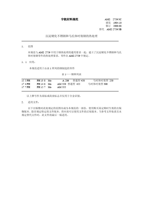
氮或氮氢混和物作为真空炉再充气淬火,在最高至 1925°F(1052°C)充许使用。 禁止使用从氨气中分离出来的氮气,对于无尺寸、无变色要求的零件,应避免使 用空气气氛和空气冷却。
3.3.2 保护涂层:当认定的工程组织批准后,充许使用补充涂层,以使完工机加表面的 氧化最小。
3.4 程序
3.4.1 酸洗:在随后的由铅、锌合金,或其它低熔温材料制成的模具成形前,零件必须 根据 ASTM A380 酸洗。
3.5.3.1 除非特别通知零件将全部机加,否则加热处理装置必须处理零件即使一些表 面没有后续的金属去除物,并且因此必须在受控的气氛中热处理至高于 1350
°F(730°C),该气氛必须符合表面污染要求,除非规定,受控的气氛对于仅 具有原材料表面零件不是必须的,除非零件是同薄板或条带制成。
3.5.3.2 专门用于热处理已去除污染的零件的炉子,不须试验。
表 2—碳化物固溶热处理时间
截面厚度
保温时间
毫米
小时,最小
<25
1
25-76(包括 25 和 76)
2
>76
3
3.4.6
校直: 当由认定的工程组织批准,校直必须或者是在环境温度,在时效期间,或 者是在加热至不高于 50°F(28°C)低于时效温度时完成。 在时效后,室温校直和热或暖校直必须随后进行应力释放。 充许校直后,在时效期间进行应力释放。
7. 拒收 参见 AMS 2759
8. 注意: 必须根据 8.1,8.2,8.3 和 AMS 2759
8.1 位于左边空白处的更改条(|)是为了方便用户定位技术更改的位置,不是编辑更改, 在本规范上一版已经做出。符号(R)在文件标题的左边,表示本规范完全修订版, 包括技术修订。更改条和(R)不用于原始版本,也不出现在不包含编辑更改的版本。
Dell S199WFP平面顯示器使用手冊说明书
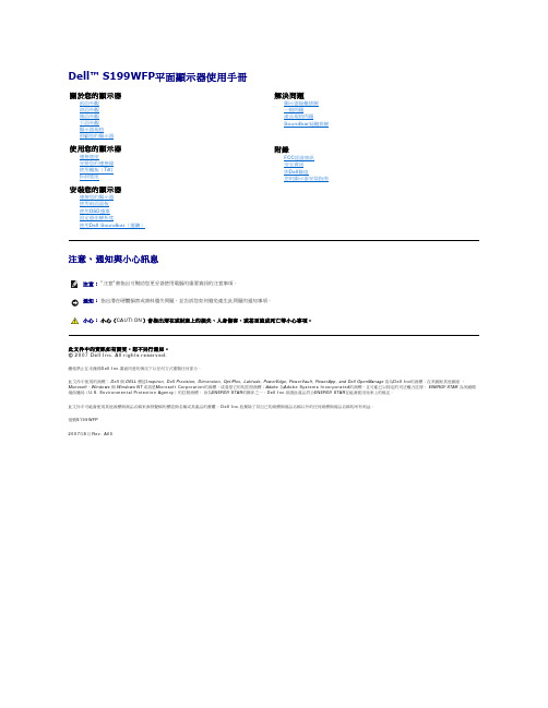
前面外觀背面外觀側面外觀下面外觀顯示器規格照顧您的顯示器1.輸入選擇2.OSD功能表/選擇按鍵3. 亮度對比度/向下按鍵4.自動調整/向上按鍵5.電源鍵(含電源指示燈)背面外觀下面外觀1電源連接接頭插入電源線。
2Dell Soundbar電源接頭連接Soundbar(選購)的電源線。
3底座防盜孔鎖附3*8螺絲防止底座脫落4DVI接頭連接電腦的DVI連接線。
5VGA接頭連接電腦的VGA連接線。
側面外觀USB接頭(下游)左側右側電源管理規格。
只有在拔下顯示器的主電源連接線時才能使顯示器達到在關閉(OFF)模式時零耗電量的目標。
針腳編號15-Pin訊號連接線的顯示器端1視訊-紅色注意: Pin 1位於右上角。
針腳訊號指定針腳訊號指定針腳訊號指定1T.M.D.S. Data 2-9T.M.D.S. Data 1-17T.M.D.S. Data 0-FCC小心: 安全指示與您的顯示器安裝指南公小心: 安全指示注檔案需要有,您可以從檔案,請載入Acrobat Reader連接您的顯示器使用前面面板使用設定最佳解析度使用小心: 在您開始執行此部分說明的任何程序前,請遵守或1.請關閉您的電腦並拔下電腦的電源線。
2. 將白色DVI或藍色VGA連接線連接至電腦與顯示器的連接頭。
3.連接電源線4.打開顯示器與電腦。
若您沒有看到任何影像,請按下輸入選擇按鍵並確定有選擇正確的輸入來源。
若仍然沒有看到任何影像,請參見顯示器疑難排解。
使用前面面板下表顯示按鈕的功能﹕請使用輸入選擇鍵來於可能已連接至顯示器的兩種不同影像訊號之間選擇輸入來源。
注意: 若顯示器沒有感應到視訊訊號,螢幕上便應該會出現漂浮且有黑色背景的自我測試功能檢查)'對話方塊。
視選擇的輸入來源不同,下面其中一個對話方塊也會持續在螢幕上捲動。
輸入選擇功能表按鍵是用來開啟及退出螢幕顯示(on-screen display;OSD)功能表,以及從功能表與子功能表退出的按鍵。
西门子 NXGPro+ 控制系统手册_操作手册说明书
3.4
单元通讯的协议 ............................................................................................................ 36
3.5
NXGpro+ 高级安全 .......................................................................................................37
3.2
功率拓扑 ......................................................................................................................34
3.3
控制系统概述 ...............................................................................................................35
NXGPro+ 控制系统手册
NXGPro+ 控制系统手册
操作手册
AC
A5E50491925J
安全性信息
1
安全注意事项
2
控制系统简介
3
NXGPro+ 控制系统简介
4
硬件用户界面说明
5
参数配置/地址
6
运行控制系统
7
高级的操作功能
8
软件用户界面
9
运行软件
10
故障和报警检修
11
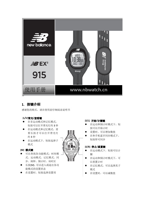
NB28-915中文说明书
步幅” 短 按 [M] 多 次 , 找 到 “ 走 路 步 幅 ( walk
stride)”或“跑步步幅(Run Stride)” 当数值在闪动时,短按[S/R]或[S/L]调整步
幅。短按[M]确认并进入下一项设置
6.2 运动模式—心率测量注意事项
圈 在运动和倒计时模式下,可
以重置计时 在记忆模式,可以选择其子
模式 在设置时,可以减数值
2.心率带设计
心率功能 本表配有心率带,所以,用户可以连续测量实时心率、平均心率和最大心率百分比,帮
助用户更好实现运动目标
1. 心率带
电极
本胸带包括 2 部分: 心率带:用来固定胸带 电极区:测量心率
校准
走完设定 的距离
走路步幅
走路和跑步步幅 为了保证速度和距离的准确度,用户使用
前需要输入自己的走路和跑步步幅 用户可以通过手动或手表自动校准步幅 自动设置走路和跑步步幅 在运动设置模式下,选择“校准走路或跑
步距离” 当数字闪动时,短按[S/L] 以 0.01 千米(10
米)为单位调整数值。设置范围是 0.01— —10 千米。 短按[S/R]开始校准 用户开始走或跑这么多距离 当完成后,短按任何按键停止校准 手表会自动算出用户的走路/跑步步幅
6.5 运动模式—心率报警
心率(每分钟心跳)
高于心率 区间
低于心率 区间
高于心率区间,报警 “滴”两下
目标心率区间(由运动目的和身 体状况决定)
低于心率区间,报警 “滴”两下
目标心率区间(由运动目的和身体状况 决定)
警告:请在开始严格的有氧训练前咨 询医生或教练来制订自己的心率区 间
TP270设备手册

缩写
本手册中使用的这些缩写词具有下列含义
AG (PLC)
可编程逻辑控制器
ANSI
美国国家标准协会
AS 511
PU 接口到 SIMATIC S5 的协议
当地时间 17:30 电话
传真
星期一至星期五 8:30 到
+65 740-7000 +65 740-7001
电子信箱 authorization@ nbgm.siemens.de
电子信箱 simatic.hotline@
电子信箱 simatic.hotline@ .sg
附录
• 技术数据 • 接口分配 • HMI 系统消息 • ESD 指南
约定
以下约定适用于本手册
电机关
操作单元显示中的文本用这种打印字体显示
变量
画面上代表变量值的符号名以这种斜体打印字体显示
画面
可供选择的功能以这种斜体字体表示
ESC 键
键和按钮的名称用不同的字体来显示
i
前言
历史 其它支持
本手册的不同版本对应于以下 ProTool CS 组态软件的不同版本
前言 目录
引言
1
功能
2
调试
3
操作
4
操作画面和画面对象
5
配方
6
归档
7
系统设置
8
安装
9
尺寸
10
选项
11
维护/保养
12
操作系统更新
海尔 天越S9 27英寸窄边框一体机台式电脑 使用说明书
金属机构件
3.2 使用注意事项
• 请勿长时间的操作电脑,这有可能导致疲劳损伤。长时间观看电脑显示屏或外部显示器 屏幕可能会导致眼睛疲劳;过长时间的让身体保持同一姿势或是重复同样的动作,将 有可能造成疲劳损伤,比如过度频繁地使用键盘、触摸板和鼠标。以劳逸结合的方式进 行操作,将会有助于提高您的工作效率。
• 请调整显示屏的角度,桌面及椅子的高度,选择最合理、最舒适的姿势。 • 当电脑正常运行 时,会将系统的热量散发到机器表面,请勿将电脑长时间的放在膝上或
• 请勿使用非本产品配备的电源适配器,也不可以将本产品的电源适配器用于其他电器设 备,这将可能造成严重的后果。
• 使用延长电源线时请注意电源插座总的电力负载,避免过载。 • 请勿放置任何物品于电源线上,也不要将电源线置于容易被踩踏的地方。 • 从插座上拔掉电源线时,请握住插头部分,不要直接拉扯电源线。 • 电源适配器工作会有一定程度的发热,请将其放置在散热条件良好的环境中。
用于连接外置麦克风,进行语言输入工作。
6 耳机输出
用于连接耳机或外置扬声器等音频输出设备。
7
使用入门
第二章 使用入门
2.1 连接AC适配器
请按照以下步骤连接适配器: 1. 取出适配器和电源线,连接适配器和电源线。 2. 将交流电源插头插入电源插座。 3. 将 AC 适配器直流输出端插入电脑电源插口。 4. 确认所有连线已经完全连接。
电源接口
本适配器为本一体机专用,请勿将之使用在其他电器设备上,其他适配器外形虽然可能与 本适配器相似,但不是本一体机专用,请勿使用。 由于各国的电压不同,电源插头的设计也不同,假如您将在其他国家使用本产品,请在当 地选购合适的电源线或配备转换插座。
8
注意事项
Siemens SCALANCE CSM 1277 产品说明书
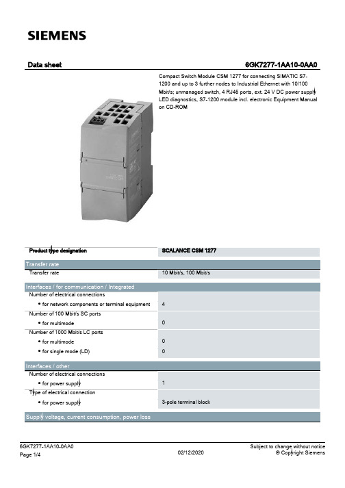
SCALANCE CSM 1277 10 Mbit/s, 100 Mbit/s
4 0 0 0
1 3-pole terminal block
6GK7277-1AA10-0AA0 Page 1/4
02/12/2020
Subject to change without notice © Copyright Siemens
SIMATIC S7-1200 device design 45 mm 100 mm 75 mm 0.15 kg
Yes Yes No No
Product functions / management, configuration, engineering Product function
● multiport mirroring
Product type designation
Transfer rate Transfer rate
Interfaces / for communication / Integrated Number of electrical connections ● for network components or terminal equipment Number of 100 Mbit/s SC ports ● for multimode Number of 1000 Mbit/s LC ports ● for multimode ● for single mode (LD)
02/12/2020
6GK7277-1AA10-0AA0 Page 4/4
02/12/2020
Subject to change without notice © Copyright Siemens
显示器 使用手册
規格 . . . . . . . . . . . . . . . . . . . . . . . . . . . . . . . . . . . . . . . . . . . . . . . . . . . . . 6-1 節能功能 . . . . . . . . . . . . . . . . . . . . . . . . . . . . . . . . . . . . . . . . . . . . . . . . . . 6-2
重要安全說明
手冊說明 . . . . . . . . . . . . . . . . . . . . . . . . . . . . . . . . . . . . . . . . . . . . . . . . . . 1-1 保養與維護 . . . . . . . . . . . . . . . . . . . . . . . . . . . . . . . . . . . . . . . . . . . . . . . . 1-2 清潔顯示器 . . . . . . . . . . . . . . . . . . . . . . . . . . . . . . . . . . . . . . . . . . . . . . . . 1-3 安全注意事項 . . . . . . . . . . . . . . . . . . . . . . . . . . . . . . . . . . . . . . . . . . . . . . 1-4
使用產品
設定最佳解析度 . . . . . . . . . . . . . . . . . . . . . . . . . . . . . . . . . . . . . . . . . . . . 3-1 標準訊號模式表 . . . . . . . . . . . . . . . . . . . . . . . . . . . . . . . . . . . . . . . . . . . . 3-2 標準訊號模式表 . . . . . . . . . . . . . . . . . . . . . . . . . . . . . . . . . . . . . . . . . . . . 3-3 標準訊號模式表 . . . . . . . . . . . . . . . . . . . . . . . . . . . . . . . . . . . . . . . . . . . . 3-4 標準訊號模式表 . . . . . . . . . . . . . . . . . . . . . . . . . . . . . . . . . . . . . . . . . . . . 3-5 標準訊號模式表 . . . . . . . . . . . . . . . . . . . . . . . . . . . . . . . . . . . . . . . . . . . . 3-6 標準訊號模式表 . . . . . . . . . . . . . . . . . . . . . . . . . . . . . . . . . . . . . . . . . . . . 3-7 標準訊號模式表 . . . . . . . . . . . . . . . . . . . . . . . . . . . . . . . . . . . . . . . . . . . . 3-8 標準訊號模式表 . . . . . . . . . . . . . . . . . . . . . . . . . . . . . . . . . . . . . . . . . . . . 3-9 標準訊號模式表 . . . . . . . . . . . . . . . . . . . . . . . . . . . . . . . . . . . . . . . . . . . 3-10 標準訊號模式表 . . . . . . . . . . . . . . . . . . . . . . . . . . . . . . . . . . . . . . . . . . . 3-11 安裝裝置驅動程式 . . . . . . . . . . . . . . . . . . . . . . . . . . . . . . . . . . . . . . . . . . 3-12 產品操作按鈕 . . . . . . . . . . . . . . . . . . . . . . . . . . . . . . . . . . . . . . . . . . . . . 3-13 使用螢幕調整功能表 (OSD:螢幕顯示) . . . . . . . . . . . . . . . . . . . . . . . 3-14
19寸机柜参数说明

19寸机柜参数说明-CAL-FENGHAI.-(YICAI)-Company One119英寸标准机柜尺寸表首先需要知道的是(1)U是一种表示服务器外部尺寸的单位,是unit(单位)的缩略语,1U=1.75英寸=44.45毫米(2)1U之间有3孔,中孔为中心,两远孔间距,两边安装柱之间距离为465(3)规定的尺寸是服务器的宽(48.26cm=19英寸)与高(4.445cm=1.75英寸的倍数)。
由于宽为19英寸,所以也将满足这一规定的机架称为“19英寸机架”。
厚度以4.445cm为基本单位,1U就是4.445cm。
具体如下表:请看下面说明标准机柜广泛应用于计算机网络设备、有无线通讯器材、电子设备的叠放,机柜具有增强电磁屏蔽、削弱设备工作噪音、减少设备地面面积占用的优点,对于一些高档机柜,还具备空气过滤功能,提高精密设备工作环境质量。
很多工程级的设备的面板宽度都采用 19 寸,所以 19 寸的机柜是最常见的一种标准机柜。
19 寸标准机柜的种类和样式非常多,也有进口和国产之分,价格和性能差距也非常明显。
同样尺寸不同档次的机柜价格可能相差数倍之多。
用户选购标准机柜要根据安装堆放器材的具体情况和预算综合选择合适的产品。
标准机柜的结构比较简单,主要包括基本框架、内部支撑系统、布线系统、通风系统。
标准机柜根据组装形式和材料选用的不同,可以分成很多性能和价格档次。
19 寸标准机柜外型有宽度、高度、深度三个常规指标。
虽然对于 19 寸面板设备安装宽度为 465.1mm ,但机柜的物理宽度常见的产品为 600mm 和800mm 两种。
高度一般从2.0M,一般机柜尺寸包括有:0.32米,0.45米,0.6米,1.0米,1.2米,1.4米,1.6米,1.8米,2.0米等。
根据柜内设备的多少和统一格调而定。
机柜的深度一般从 350mm-1000mm ,根据柜内设备的尺寸而定,通常厂商也可以定制特殊深度的产品,常见的成品 19 寸机柜深度为 500mm 、 600mm 、 700mm 、800mm 。
27 英寸(685.8 毫米)10 英寸(254 毫米)顶部或后尘囊式风扇说明书

27VentingTop or Rear OutletThis unit is supplied with a top vent outlet which can be fi eld-converted to a rear vent outlet. See Appliance Preparation section for more information.Vent MaterialThis unit is approved for installation using 4 x 6-5/8 inches co-axial direct vent pipe and accessories as listed in the Approved VentingComponents section on pages 53–54 of this manual. Follow the installation instructions supplied with the individual venting accessories.This unit may also be converted to co-linear (2 x 3 in) venting for use in solid-fuel burning fi replaces and chimneys using adapters and accessories—see list in the Approved Venting Components section on pages 53–54 of this manual.Vent SealingSeal all outer coaxial pipe and elbow joints, including sectioned elbow joints, using high quality, high tem-perature 2 inch wide self-adhesive aluminum foil tape (Nashua-322-2 brand or similar). Wrap the tape com-pletely around all joints and press fi rmly to seal.A high temperature black silicone sealant may be used in the outer joints as a substitute to foil tape.Ensure all the pipe joints have a minimum of 1 ¼ inch overlap.Wall ThicknessThe appliance vent is suitable for penetrating acombustible wall assembly up to 8 inches in thickness. A non-combustible wall can be of any thickness up to the maximum horizontal run of vent pipe allowed for the particular installation.Framing Vent in Combustible Walls & CeilingsWhen penetrating through combustible walls andceilings, frame a minimum of 10 in x 10 in opening and ensure that the insulation is kept clear of the vent pipe using either a wall thimble or an attic insulation shield.Follow the installation instructions supplied with the individual venting components.Important Installer Notice –Weather Sealing & Vapor BarriersIt is the installer’s responsibility to ensure that vent installations through exterior walls are caulked and weatherproofed in such a manner as to:• Prevent rain water from entering the wall from the weather side by adequately caulking the outer vent plate to the exterior wall surface. • Prevent moisture inside the home frompenetrating into the wall structure by ensuring the inside wall plate is adequately sealed to the inside vapor barrier.• Prevent rain water and moisture from entering the walls by sealing the joints between the outer vent tube and the inner and outer wall plates.We recommend the use of a high qualitypolyurethane sealant.All horizontal pipe runs must be graded 1/4 inch per foot upwards in the direction of the exhaust fl ow. The fi nal pipe length, when terminating through the wall may be graded downwards slightly to prevent water migration.QUALIFIED INSTALLERModel 1700I28HORIZONTAL TERMINATION2-PIECEWALL THIMBLEPIPE LENGTH HORIZONTAL TERMINATION2-PIECEWALL THIMBLEPIPE LENGTHPIPE LENGTHPIPE LENGTHPIPE LENGTH90˚ ELBOWCEILING FIRESTOPATTIC FIRESTOP ATTICINSULATION SHIELDFLASHINGSTORM COLLARVERTICAL TERMINATIONPIPE LENGTH90˚ ELBOW90˚ ELBOWCo-axial VentingTypical Co-axial Venting ComponentsRear VentTop Vent Top VentQUALIFIED INSTALLER29Minimum 12” pipe sectionsupplied with unithorizontal pipe1” min. around bottom & sides Allowable Co-Axial Vent Con fi gurations How to Read the Venting ChartThe chart below applies to co-axial roof or wall termination.1. Minimum 12 inch vertical pipe section requiredwithin vent system either right off unit or down-stream after horizontal run.2. The total length of the vent pipe cannot exceed40 feet.3. The minimum vertical height with roof terminationis 6 feet.4. Any combination of rise and run can be used aslong as they are within the allowable limits shown on the chart below.5. A maximum of 4 x 90 degrees elbows—orequivalent (2 x 45 degrees = 90 degrees)—canbe used. Excludes the 45 degrees take-off elbow shipped with the appliance.6. Each 90 degrees elbow installed on the horizontalplane is equivalent to a 3 feet horizontal pipe;therefore, 3 feet must be subtracted from allowable horizontal run. (45 degrees elbow is equivalent to 18 inches horizontal pipe.)7. All horizontal pipe runs must be graded 1/4 inch perfoot upwards in the direction of the exhaust fl ow. The fi nal pipe length, when terminating through the wall may be graded downwards slightly to prevent water migration.8. A restrictor adjustment is required for mostinstallations having a vertical rise—see next section.Note: The restrictor is shipped installed at the exhaust exit of the fi rebox.Co-axial VentingExample 1V Value = V1 (3’) + V2 (2’) + V3 (1’)= 6’H Value = H1 (3’) + H2 (2’) = 5’Restrictor position # 2 requiredvert pipe riseQUALIFIED INSTALLER30Position #1Position #2Position #3Position #4Position #5Inside fi rebox—roof venting portRestrictorThe restrictor is located in the roof of the fi rebox hidden above the top liner panel. Adjust the restrictor before installation of the top liner panel. Should subsequent adjustment be required, you will need to remove the top liner panel—see page 41.ALL INSTALLATIONS REQUIRE A RESTRICTOR for improved fl ame picture and performance. This unit is supplied with a pre-fi tted restrictor having fi ve different positions or settings. The restrictor is shipped mounted at the maximum open position. The level of restriction required depends on the vertical rise in the venting system and, to a lesser degree, the horizontal run and number of elbows.The amount of restriction is based on laboratory tests. The ideal restrictor position may vary slightly, especially when the vent pipe length is near the limits of the acceptable con fi gurations for each type of restrictor.The chart on the previous page shows the ventrestrictor required relative to the length of the vent pipe. To set the restrictor position:1. Establish the required position of the restrictor looking up the venting table on the previous page.2. Release the screws (2) on each side of the restrictor already installed on the fi rebox roof port .3. Slide the restrictor in the required position.4. Tighten the screws.Co-axial VentingQUALIFIED INSTALLER31VGA(open on one side) Normal ceiling/sof fi t clearances apply.KEY VENT TERMINAL LOCATIONS - MINIMUM DISTANCESMINIMUMCLEARANCE Inches Cm A Clearance above grade, verandah, porch, deck or balcony 1230B Clearance to window or door that may be opened1230C Clearance to permanently closed window (recommended to prevent condensation on window) 1230D Vertical clearance to ventilated sof fi t located above the terminal within a horizontal distance of 2 feet (60 cm) from the center-line of the terminal 1846E Clearance to unventilated sof fit 1230F Clearance to outside corner 1230G Clearance to inside corner1230H Horizontal clearance to center-line of meter/regulator assembly located within 15 feet (4,6 m) below the terminal3690I Clearance to service regulator vent outlet3690J Clearance to non-mechanical air supply inlet to the building or the combustion air inlet to any other appliance1230K Clearance to a mechanical air supply inlet72180LClearance above paved sidewalk or a paved driveway located on public propertyNote : A vent must not terminate directly above a sidewalk or paved driveway, which is located between two single-family dwellings and serves both dwellings 84210MClearance under a verandah, porch, deck or balconyOnly permitted if veranda, porch, deck or balcony is fully open on a minimum of 2 sides beneath the fl oor1230Note:Local codes and regulations may require different clearances.Vent Termination• The vent terminal must be located on an outside wall or through the roof.• This direct vent appliance is designed to operate when an undisturbed air fl ow hits the outside vent terminal from any direction.• The minimum clearances from this terminal that must be maintained when located on an outside wall are shown in the fi gure below. Any reduction in these clearances could result in a disruptionof the air fl ow or a safety hazard. Local codes or regulations may require greater clearances.• The vent terminal must not be recessed into a wall or siding.• The vent terminal should be positioned where it will not be covered by snowdrifts.• Sidewall vent terminations within 7’ of grade require a terminal guard such as the 845TG.Co-axial VentingQUALIFIED INSTALLER323” min.bend radiusDura-Vent #46DVA-GCL Co-Axialto Co-Linear AdapterRoof PitchMinimum "H" (feet)Flat to 7/121'Over 7/12 to 8/121.5'Over 8/12 to 9/122’Over 9/12 to 10/122.5’Over 10/12 to 11/123.25’Over 11/12 to 12/124’Over 12/12 to 14/125’Overhang should not extend beyond vent if within 48” of termination capHorizontal overhangVertical wallMin. 24”(unvented soffit)Min. 36”(vented soffit)capMin.18”Storm collarRoof flashing‘H’Vertical Vent TerminationCo-axial VentingConversion to Co-Linear Liners using generic Co-Linear AdaptersCo-linear portion of vent system may only be installed within a solid-fuel burning fi replace and chimney.The appliance must not be connected to a chimney fl ue serving a separate solid-fuel burning appliance.Requires a Co-Axial to Co-Linear appliance Adapter, two lengths of 2-ply 3” dia. fl exible chimney liner approved for venting gas appliances, a co-linear termination kit and fl ashing or a co-linear to co-axial adapter and either a high wind vertical vent terminal cap or a low pro fi le verticaltermination. Firebox zero clearance standoffs suppliedwith the heater are not required for this application .Rules for Co-Linear Venting• Maximum 40 feet vertical pipe• Minimum 10 feet vertical• Maximum offset 8 feet with liners at minimum 45 degrees from horizontal plane• Restrictor: Use #4 position for all co-linearinstallations—refer to page 30 for restrictor positioning.Co-linear VentingQUALIFIED INSTALLER3310”10”3” Inlet & Exhaust Collars7-5/8” dia.collar559CLT Co-Linear Terminal Alternate to 559CLT/559FSK ConversionTerminal CapCo-Linear to Co-AxialAdapterFlashingLinear rear outlet with co-linear adapter Linear top outlet with co-linear adapter23-3/8” (594 mm)Co-linear VentingCo-linear terminal con fi gurationsDimensions with co-linear adapterDimensions shown are with Dura-Vent co-linear adapter. Other manufacturers’ adapters may vary.QUALIFIED INSTALLER。
Philips 27BDL9112L 限制无边框 LED 显示墙说明书
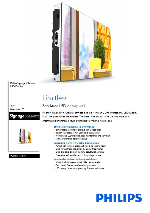
Philips Signage SolutionsLED Display27"Direct View LED 27BDL9112L LimitlessBezel-free LED display wall.Fill their imagination. Create seamless displays. With an L-Line Professional LED Display Wall, the possibilities are endless. The bezel-free design, wide viewing angle and breathtaking brightness ensure authoritative imaging. At any size.Effortless setup. Reliable performance.•Join multiple cabinets to achieve higher resolution•Built-in rear cable cover. Easy cable management•Front-access LED modules. Easy maintenance and servicing•High-performance gold-wire LEDsImmersive viewing. Versatile LED solution.•Perfect clarity. From broadcast studio to control room•Ultra-high refresh rate. Smooth, judder-free images•Ultra-thin pixel pitch of 1.2 mm. Beautiful at any size•Create bezel-free video walls of any shape or sizeSpectacular picture. Endless possibilities.•Ultra-high brightness even at wide viewing angles•Zero bezel. Create seamless display screens•LED display. Superb image quality. Perfect uniformityIssue date 2022-10-07Version: 11.0.112 NC: 8670 001 52762EAN: 87 12581 75858 5© 2022 Koninklijke Philips N.V.All Rights reserved.Specifications are subject to change without notice.Trademarks are the property of Koninklijke Philips N.V.or their respective owners. SpecificationsLED Display 27" Direct View LEDHighlights LED display. Superb image Create bezel-free video walls of any shape, size or resolution. The modular design of Philips Professional LED cabinets means you can adapt to any space. Build vast, immersive installations or assemble intriguing patterns. Easily create video walls that flow seamlessly around doorways and other openings.Built-in rear cable cover.Your Philips Professional LED Display features built-in rear cable covers to keep power and data cables tidy. Display cabinets can also be daisy-chained for both power and data, allowing you to minimise clutter and speed up installation.High-performance gold-wire LED Philips Professional LED Displays use high-performance gold-wire LEDs, which are energy efficient and cost effective. The light is brighter and the LEDs last longer.Create bezel-free video walls Simply connect multiple LED display cabinets to create the resolution you want, whether it's 4K, 8K or even higher. Compared to LCD screens, LED displays boast higher refresh rates that enable smoother images. Whatever the application, you'll thrill them with crystal-clear picture quality.Front-access LED modules.Internal electronics are easy to access for servicing or maintenance. Each of the eight LED modules in a cabinet can be removed using a dedicated magneticJIG tool, which lifts the module out from the front.Picture/Display •Brightness before calibration: 900 nits •Brightness after calibration: 800 nits •Colour temperature default: 6500±500 K •Colour temperature adjust range: 4000~9500 K (by software)•Viewing Angle (H / V): 160 / 160 degree •Brightness Uniformity: >=97%•Contrast ratio (typical): >=3000:1•Calibration (brightness/colour): Supported •Refresh rate (Hz): 1920~3840•Frame frequency (Hz): 50 & 60•Aspect ratio: 16:9•Picture enhancement: Wide colour gamut display •Placement: Landscape •Usage: 24/7 hrs, Indoor Convenience •Signal control loop through: RJ45•Ease of installation: Guide pins, Light weight, Locking mechanism for cabinet •Power loop through: For 230 V environments: 8 cabinets or less, for 110 V environments: 4 cabinets or less Operating conditions •Temperature range (operation): -20~45 °C •Temperature range (storage): -20~50 °C •Humidity range (operation)[RH]: 10~80%•Humidity range (storage) [RH]: 10~85% Power •Max Power consumption (W): <=160 W W •Consumption (Typical): <=54 W •Input voltage: AC100~240 V (50 and 60 Hz)•BTU Value m2: 2624 BTU/m2Miscellaneous •Warranty:3 years •Regulatory approvals: FCC SDOC, Part 15, EMC Class B, EN55032, EN55035, EN61000-3-2, EN61000-3-3, IEC/UL60950, IEC/UL62368, IEC62471, RoHS Cabinet •Cabinet size (mm): 608 x 342 x 55•Cabinet diagonal (inch): 27.5•Cabinet resolution (W x H): 480 × 270•Weight (kg): 8(+/-0.4 Kg)•Cabinet pixels (Dot): 129,600•Cabinet area (m2): 0.2079•Power connector: In/Out(C14/C13)•Data connector: RJ45•Cabinet construction: Die-Casting Aluminium •Receiving card quantity: 2 pcs •Receiving card spec.: A7S/A5S Plus •Receiving card brand: Novastar Module •LED type: SMD 1010 Gold wire •Pixel constitution: 1R1G1B•LED lifetime(Hrs): 100 000•Pixel pitch (mm): 1.266•Module size (WxHxD in mm): 152 x 171 x 10•Module resolution (WxH pixels): 120 x 135Accessories•Power loop through cable: 1 pcs •LAN cable (RJ45, CAT-5): 1 pcs •Common connecting piece: 4 pcs •Screw bolt: 4 pcs (M8*20) (Inner Hexagon Screw)•QSG:1pcs。
Modern MD271QPW 商品说明书
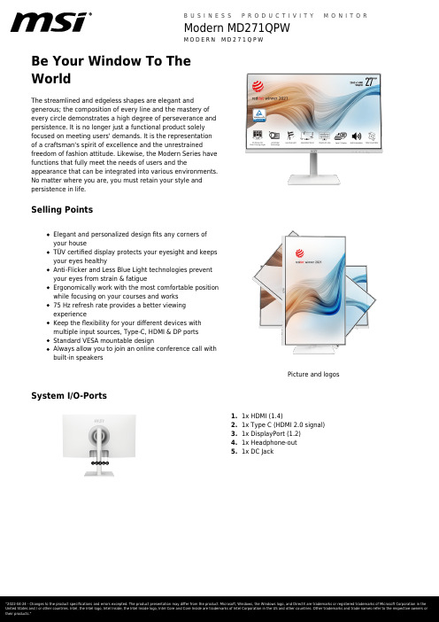
Be Your Window To TheWorldThe streamlined and edgeless shapes are elegant andgenerous; the composition of every line and the mastery ofevery circle demonstrates a high degree of perseverance andpersistence. It is no longer just a functional product solelyfocused on meeting users' demands. It is the representationof a craftsman's spirit of excellence and the unrestrainedfreedom of fashion attitude. Likewise, the Modern Series havefunctions that fully meet the needs of users and theappearance that can be integrated into various environments.No matter where you are, you must retain your style andpersistence in life.Selling PointsElegant and personalized design fits any corners ofyour houseTÜV certified display protects your eyesight and keepsyour eyes healthyAnti-Flicker and Less Blue Light technologies preventyour eyes from strain & fatigueErgonomically work with the most comfortable positionwhile focusing on your courses and works75 Hz refresh rate provides a better viewingexperienceKeep the flexibility for your different devices withmultiple input sources, Type-C, HDMI & DP portsStandard VESA mountable designAlways allow you to join an online conference call withbuilt-in speakersPicture and logos System I/O-Ports1.1x HDMI (1.4)2.1x Type C (HDMI 2.0 signal)3.1x DisplayPort (1.2)4.1x Headphone-out5.1x DC JackSpecificationAnnual Energy Consumption (KWh)NAScreen Size27" (69 cm)Active Display Area (mm)596.736(H) X 335.664(V) Curvature FlatPanel Type IPSResolution2560x1440 (WQHD)Pixel pitch0.2331(H)X0.2331(V)Aspect Ratio16:9Dynamic Refresh Rate technology NAHDR (High dynamic range)NASDR Brightness (nits)250HDR Brightness (Peak nits)NAContrast Ratio1000:1DCR (Dynamic Contrast Ratio)100000:1Signal Frequency30~112 KHz(H) / 48~75 Hz(V) Activated Range NARefresh Rate75HzResponse Time (MPRT)NAResponse Time (GTG)5msResponse Time (Tr + Tf)14msView Angles178°(H)/178°(V)Surface Treatment Anti-glareNTSC (CIE1976 area percentageoverlap)95.10%/80.10%NTSC (CIE1931 area percentageoverlap)77.30%/72.00%sRGB (CIE1976 area percentageoverlap)109.02%/97%sRGB (CIE1931 area percentageoverlap)109.13%/96.20%Adobe RGB (CIE1976 area percentageoverlap)93.34%/85.70%Adobe RGB (CIE1931 area percentageoverlap)80.90%/74.80%DCI-P3 (CIE1976 area percentageoverlap)86.92%/83.20%DCI-P3 (CIE1931 area percentageoverlap)80.45%/79.60%Rec.709 (CIE1976 area percentageoverlap)NARec.709 (CIE1931 area percentageoverlap)NARec.2020 (CIE1976 area percentageoverlap)N/ARec.2020 (CIE1931 area percentageoverlap)N/ADisplay Colors16.7MColor bit8 bitsNote_DP2560 x 1440 (Up to 75Hz) Note_HDMI2560 x 1440 (Up to 75Hz) Note_DVI N/AHDMI1HDMI version 1.4HDMI HDCP version 2.2DisplayPort1DisplayPort version 1.2DisplayPort HDCP version 2.2Thunderbolt version NAThunderbolt HDCP version NAUSB Type C (DisplayPort Alternate)1DVI NAD-Sub NAMic-in NAMic-in upstream N/AHeadphone-out1Audio Combo NALock type Kensington LockSpeaker N/AUSB 2.0 Type B NAUSB 3.2 Gen 1 Type B NAThunderbolt NAUSB 2.0 Type A NAUSB 2.0 Type C NAUSB 3.2 Gen 1 Type A NAUSB 3.2 Gen 1 Type C NAUSB 3.2 Gen 2x2 Type C NAUSB 3.2 Gen 2x2 Type A NACard Reader NAFeature Frameless design WebCam N/APower Type External Adaptor 19V 3.42A Power Input100~240V, 50/60Hz Adapter's KC safety Number NAPower Cord Type C13QC Output NAQC Output Power NAPD Output NAPD Output Power NAAdjustment (Tilt)-5° ~ 20°Adjustment (Swivel)-30° ~ 30°Adjustment (Height)0 ~ 110 mmAdjustment (Pivot)-90° ~ 90°VESA Mounting75x75mmFrameless Design YesOuter Carton Dimension (WxDxH) (mm)893 x 167 x 464Outer Carton Dimension (WxDxH) (inch)35.16 x 6.57 x 18.27 Product Dimension with Stand (WxDxH) (mm)613 x 200 x 401Product Dimension with Stand (WxDxH) (inch)24.13 x 7.87 x 15.79613 x 72 x 362Product Dimension without Stand (WxDxH)(mm)24.13 x 2.83 x 14.25 Product Dimension without Stand (WxDxH)(inch)Stand Dimension (WxDxH) (mm)230 x 200 x 415Stand Dimension (WxDxH) (inch)9.06 x 7.87 x 16.34Inside Carton Dimension (WxDxH) (mm)883 x 157 x 442Inside Carton Dimension (WxDxH) (inch)34.76 x 6.18 x 17.4 Weight (Net kg) 5.8Weight (Gross kg)8.44Weight Without Stand (kg)N/ADisplayPort Cable0HDMI Cable1DVI Cable0USB Type A to Type B Cable0USB Type C to Type A Cable0USB Type C to Type C Cable0Thunderbolt Cable0VGA Cable03.5mm audio Cable03.5mm combo audio Cable0Power Cord1AC Adaptor1Warranty Card1Quick Guide1Warranty36MEntity MKT Name Modern MD271QPWColor ID1/White-WhiteEAN4719072817244。
27寸显示器长宽是多少厘米
27寸显示器长宽是多少厘米推荐文章22寸显示器长宽各是多少厘米的方法热度:21.5显示器长宽是多少有多大热度:显示器分辨率调节多少最合适热度:显示器22寸最佳分辨率是多少热度: 23英寸显示器lol分辨率多少合适热度:显示器(display)通常也被称为监视器。
显示器是属于电脑的I/O 设备,即输入输出设备。
它是一种将一定的电子文件通过特定的传输设备显示到屏幕上再反射到人眼的显示工具。
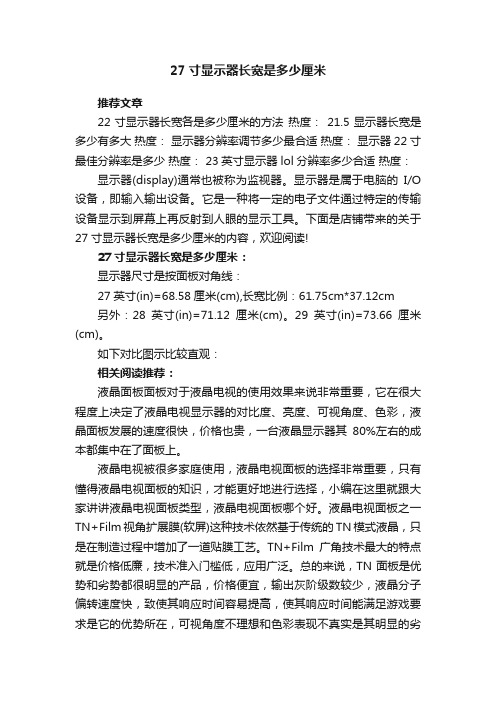
下面是店铺带来的关于27寸显示器长宽是多少厘米的内容,欢迎阅读!27寸显示器长宽是多少厘米:显示器尺寸是按面板对角线:27英寸(in)=68.58厘米(cm),长宽比例:61.75cm*37.12cm另外:28英寸(in)=71.12厘米(cm)。
29英寸(in)=73.66厘米(cm)。
如下对比图示比较直观:相关阅读推荐:液晶面板面板对于液晶电视的使用效果来说非常重要,它在很大程度上决定了液晶电视显示器的对比度、亮度、可视角度、色彩,液晶面板发展的速度很快,价格也贵,一台液晶显示器其80%左右的成本都集中在了面板上。
液晶电视被很多家庭使用,液晶电视面板的选择非常重要,只有懂得液晶电视面板的知识,才能更好地进行选择,小编在这里就跟大家讲讲液晶电视面板类型,液晶电视面板哪个好。
液晶电视面板之一TN+Film视角扩展膜(软屏)这种技术依然基于传统的TN模式液晶,只是在制造过程中增加了一道贴膜工艺。
TN+Film广角技术最大的特点就是价格低廉,技术准入门槛低,应用广泛。
总的来说,TN面板是优势和劣势都很明显的产品,价格便宜,输出灰阶级数较少,液晶分子偏转速度快,致使其响应时间容易提高,使其响应时间能满足游戏要求是它的优势所在,可视角度不理想和色彩表现不真实是其明显的劣势。
因此现在市场中所出售的采用TN面板的液晶显示器普遍采用改良型的TN+FILM(补偿膜)用于弥补TN面板可视角度方面的不足,同时色彩抖动技术的使用也使得原本只能显示26万色的TN面板获得了16.2M的显示能力。
久菱变频器
变 频 器 乃 电 力 电 子 产 品,为了您 的 安 全 ,请 务 必 由 专 业 的 电 机 工 程 人 员 安 装、调 试 及 调 整 参 数 。本 手 册 中
JL-M系列使用说明书
JL-M系列 七、试运行……………………………………………… 19 1、运行前检查……………………………………………………19 2、试运行方式……………………………………………………19 八、功能一览表………………………………………… 20 九、功能说明…………………………………………… 27 十、保养维护、故障信息及排除方法…………………73 1、维护检查注意事项……………………………………………73 2、定期检查项目…………………………………………………73 3 、故 障 信 息 及 故 障 排 除 ………………………………………7 4 4、故障及分析……………………………………………………77 十一、周边设施选用及配置……………………………79 1、选件……………………………………………………………79 2、配置……………………………………………………………80 十二、附录……………………………………………… 81 附录一:简单应 用 举 例…………………………………………81 附 录 二 :机 器 外 型 及 安 装 尺寸…………………………… 8 3 附 录 三 :M 系 列 键 盘 操 作 及 实 例 ………………………… 8 5 附录四:使 用者 记录 及 反馈…………………………………8 7
控端
器、外部异常、程序运行等指示及报警
制
