SZ5551中文资料
2N5551中文资料(fairchild)中文数据手册「EasyDatasheet - 矽搜」
50 VCB = 100V
10
10
10
1β
100 Co
o
125 C
0.1
o
-40 Co
25 Co
75 C
- CCEO(SALT)LECTOR-EMITTER VOLTAGE [V]
0.01
V
1
10
100
IC- COLLECTOR CURRENT [mA]
Figure 2. Collector-Emitter Saturation Voltage vs.
芯片中文手册,看全文,戳
2N5551 / MMBT5551 NPN通用放大器
2013年6月
描写
该装置是专为通用高压放大器和气体放电的显示驱动程序.
2N5551
TO-92
MMBT5551
3
2
1 SOT-23
Marking: 3S 1. Base 2. Emitter 3. Collector
MMBT5551
350 2.8
357
Units
mW mW/°C °C/W °C/W
2
芯片中文手册,看全文,戳
电气特性
(4)
价值观是在T 符
A = 25°C除非另有说明. 参数
断特性
V(BR)CEO 集电极 - 发射极击穿电压 V(BR)CBO 集电极基击穿电压 V (BR)EBO 发射极基极击穿电压
Value
160 180
6 600 -55到+150
2N5551 / MMBT5551 - NPN通用放大
器
Units
V V V mA °C
热特性
价值观是在T
555中文资料

555芯片引脚图及引脚描述555的8脚是集成电路工作电压输入端,电压为5~18V,以UCC表示;从分压器上看出,上比较器6脚A1的5脚接在R1和R2之间,所以5脚的电压固定在2UCC/3上;下比较器A2接在R2与R3之间,A2的同相输入端电位被固定在UCC/3上。
1脚为地。
2脚为触发输入端;3脚为输出端,输出的电平状态受触发器控制,而触发器受上比较器6脚和下比较器2脚的控制。
当触发器接受上比较器A1从R脚输入的高电平时,触发器被置于复位状态,3脚输出低电平;2脚和6脚是互补的,2脚只对低电平起作用,高电平对它不起作用,即电压小于1Ucc/3,此时3脚输出高电平。
6脚为阈值端,只对高电平起作用,低电平对它不起作用,即输入电压大于2 Ucc/3,称高触发端,3脚输出低电平,但有一个先决条件,即2脚电位必须大于1Ucc/3时才有效。
3脚在高电位接近电源电压Ucc,输出电流最大可打200mA。
4脚是复位端,当4脚电位小于0.4V时,不管2、6脚状态如何,输出端3脚都输出低电平。
5脚是控制端。
7脚称放电端,与3脚输出同步,输出电平一致,但7脚并不输出电流,所以3脚称为实高(或低)、7脚称为虚高。
1 555集成电路的框图及工作原理555集成电路开始是作定时器应用的,所以叫做555定时器或555时基电路。
但后来经过开发,它除了作定时延时控制外,还可用于调光、调温、调压、调速等多种控制及计量检测。
此外,还可以组成脉冲振荡、单稳、双稳和脉冲调制电路,用于交流信号源、电源变换、频率变换、脉冲调制等。
由于它工作可靠、使用方便、价格低廉,目前被广泛用于各种电子产品中,555集成电路内部有几十个元器件,有分压器、比较器、基本R-S触发器、放电管以及缓冲器等,电路比较复杂,是模拟电路和数字电路的混合体,如图1所示。
555芯片管脚介绍555集成电路是8脚封装,双列直插型,如图2(A)所示,按输入输出的排列可看成如图2(B)所示。
2N5551规格书
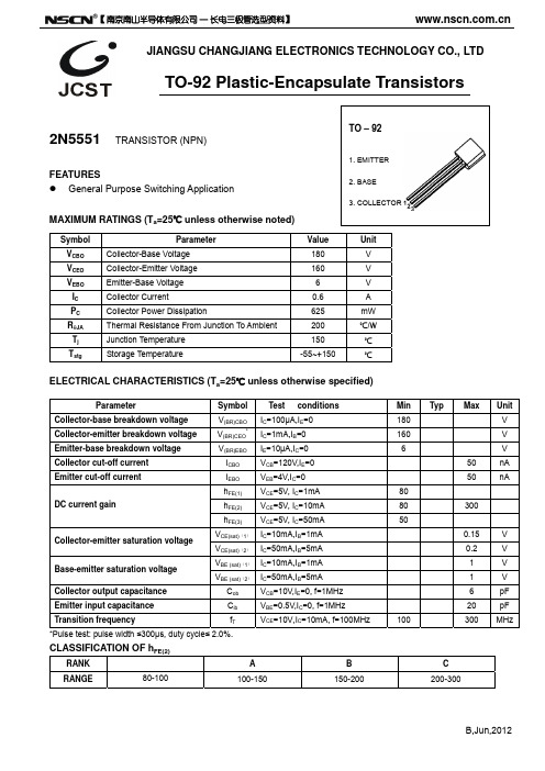
JIANGSU CHANGJIANG ELECTRONICS TECHNOLOGY CO., LTDTO-92 Plastic-Encapsulate Transistors2N5551 TRANSISTOR (NPN)FEATURESz General Purpose Switching ApplicationMAXIMUM RATINGS (T a =25℃ unless otherwise noted)ELECTRICAL CHARACTERISTICS (T a =25℃ unless otherwise specified)ParameterSymbol Test conditions Min Typ Max UnitCollector-base breakdown voltage V (BR)CBO I C =100µA,I E =0 180 V Collector-emitter breakdown voltage V (BR)CEO*I C =1mA,I B =0 160 V Emitter-base breakdown voltage V (BR)EBOI E =10µA,I C =0 6 VCollector cut-off current I CBO V CB =120V,I E =0 50 nAEmitter cut-off current I EBO V EB =4V,I C =0 50 nAh FE(1) V CE =5V, I C =1mA 80h FE(2) V CE =5V, I C =10mA 80 300DC current gainh FE(3)V CE =5V, I C =50mA 50V CE(sat)(1) I C =10mA,I B =1mA 0.15 VCollector-emitter saturation voltage V CE(sat)(2) I C =50mA,I B =5mA 0.2 VV BE (sat)(1) I C =10mA,I B =1mA 1 V Base-emitter saturation voltage V BE (sat)(2)I C =50mA,I B =5mA 1 VCollector output capacitance C ob V CB =10V,I E =0, f=1MHz 6 pF Emitter input capacitance C ib V BE =0.5V,I C =0, f=1MHz 20 pF Transition frequencyf TV CE =10V,I C =10mA, f=100MHz100300 MHz*Pulse test: pulse width ≤300μs, duty cycle ≤ 2.0%.CLASSIFICATION OF h FE(2)RANK A B C RANGE80-100100-150 150-200 200-300Symbol Parameter Value UnitV CBO Collector-Base Voltage 180 V V CEO Collector-Emitter Voltage 160 V V EBO Emitter-Base Voltage 6 V I C Collector Current0.6 A P C Collector Power Dissipation625 mW R θJA Thermal Resistance From Junction To Ambient 200 ℃/W T j Junction Temperature 150 ℃ T stgStorage Temperature-55~+150℃3. COLLECTOR B,Jun,2012【南京南山半导体有限公司 — 长电三极管选型资料】C O L L E C T O R C U R R E N T I C (m A )COLLECTOR CURRENT I C (mA)T R A N S I T I O N F R E Q U E N C Y f T (M H z )2N5551Typical CharacteristicsAMBIENT TEMPERATURE T a ()℃C O L L E C T O R C U R R E N T I (m A )B A S E -E M I T T E R S A T U R A T I O NV O L T A G E V B E s a t (V )B,Jun,2012【南京南山半导体有限公司 — 长电三极管选型资料】。
PMST5551中文资料

DATA SHEETProduct specificationSupersedes data of 1997May 201999Apr 29DISCRETE SEMICONDUCTORSPMST5550; PMST5551NPN high-voltage transistorsbook, halfpageM3D187NPN high-voltage transistorsPMST5550; PMST5551FEATURES•Low current (max. 300mA)•High voltage (max. 160V).APPLICATIONS•Switching and amplification in high voltage applications such as telephony.DESCRIPTIONNPN high-voltage transistor in a SOT323 plastic package.PNP complement: PMST5401.MARKINGNote1.∗=-:Made in Hong Kong.∗=t :Made in Malaysia.TYPE NUMBER MARKING CODE (1)PMST5550∗1F PMST5551∗G3PINNINGPIN DESCRIPTION1base 2emitter 3collectorFig.1 Simplified outline (SOT323) and symbol.handbook, halfpage231MAM062321Top viewLIMITING VALUESIn accordance with the Absolute Maximum Rating System (IEC 134).Note1.Transistor mounted on an FR4 printed-circuit board.SYMBOL PARAMETERCONDITIONSMIN.MAX.UNITV CBOcollector-base voltage open emitterPMST5550−160V PMST5551−180VV CEOcollector-emitter voltage open basePMST5550−140V PMST5551−160V V EBO emitter-base voltage open collector −6V I C collector current (DC)−300mA I CM peak collector current −600mA I BM peak base current −100mA P tot total power dissipation T amb ≤25°C; note 1−200mW T stg storage temperature −65+150°C T j junction temperature−150°C T amb operating ambient temperature−65+150°CNPN high-voltage transistorsPMST5550; PMST5551THERMAL CHARACTERISTICS Note1.Transistor mounted on an FR4 printed-circuit board.CHARACTERISTICST amb =25°C unless otherwise specified.Note1.Pulse test: t p ≤300µs;δ≤0.02.SYMBOL PARAMETERCONDITIONS VALUE UNIT R th j-a thermal resistance from junction to ambientnote 1625K/WSYMBOL PARAMETERCONDITIONSMIN.MAX.UNIT I CBOcollector cut-off current I E =0; V CB =100V−100nA PMST5550I E =0; V CB =100V; T amb =100°C −100µA collector cut-off current I E =0; V CB =120V−50nA PMST5551I E =0; V CB =120V; T amb =100°C −50µA I EBO emitter cut-off current I C =0; V EB =4V −50nAh FEDC current gain V CE =5V; (see Fig.2)PMST5550I C =1mA 60−I C =10mA 60250I C =50mA; note 120−DC current gain V CE =5V; (see Fig.2)PMST5551I C =1mA 80−I C =10mA 80250I C =50mA; note 130−V CEsatcollector-emitter saturation voltageI C =10mA; I B =1mA −150mVcollector-emitter saturation voltage I C =50mA; I B =5mA; note 1PMST5550−250mV PMST5551−200mV V BEsatbase-emitter saturation voltage I C =10mA; I B =1mA −1V base-emitter saturation voltage I C =50mA; I B =5mA; note 1PMST5550− 1.2V PMST5551−1V C c collector capacitance I E =i e =0; V CB =10V; f =1MHz −6pF C e emitter capacitance I C =i c =0; V EB =0.5V; f =1MHz −30pF f T transition frequency I C =10mA; V CE =10V; f =100MHz 100300MHz Fnoise figure I C =200µA; V CE =5V; R S =2k Ω;f =10Hz to 15.7kHzPMST5551−8dBNPN high-voltage transistors PMST5550; PMST5551Fig.2 DC current gain; typical values.handbook, full pagewidth01201604080MGD81410−1110102103h FEI C mAV CE = 5 VNPN high-voltage transistorsPMST5550; PMST5551PACKAGE OUTLINEUNIT A 1max b p c D E e 1H E L p Q w v REFERENCESOUTLINE VERSION EUROPEAN PROJECTIONISSUE DATE IECJEDECEIAJ mm0.11.10.80.40.30.250.102.21.81.351.150.65e 1.32.22.00.230.130.20.2DIMENSIONS (mm are the original dimensions)0.450.15SOT323SC-70w M b pD e 1e ABA 1L pQdetail XcH EE v M AAB y01 2 mmscaleA X123Plastic surface mounted package; 3 leadsSOT32397-02-28NPN high-voltage transistors PMST5550; PMST5551DEFINITIONSData sheet statusObjective specification This data sheet contains target or goal specifications for product development. Preliminary specification This data sheet contains preliminary data; supplementary data may be published later. Product specification This data sheet contains final product specifications.Limiting valuesLimiting values given are in accordance with the Absolute Maximum Rating System (IEC 134). Stress above one or more of the limiting values may cause permanent damage to the device. These are stress ratings only and operation of the device at these or at any other conditions above those given in the Characteristics sections of the specification is not implied. Exposure to limiting values for extended periods may affect device reliability.Application informationWhere application information is given, it is advisory and does not form part of the specification.LIFE SUPPORT APPLICATIONSThese products are not designed for use in life support appliances, devices, or systems where malfunction of these products can reasonably be expected to result in personal injury. Philips customers using or selling these products for use in such applications do so at their own risk and agree to fully indemnify Philips for any damages resulting from such improper use or sale.NPN high-voltage transistors PMST5550; PMST5551NOTESInternet: Philips Semiconductors – a worldwide company© Philips Electronics N.V. 1999SCA63All rights are reserved. Reproduction in whole or in part is prohibited without the prior written consent of the copyright owner.The information presented in this document does not form part of any quotation or contract, is believed to be accurate and reliable and may be changed without notice. No liability will be accepted by the publisher for any consequence of its use. Publication thereof does not convey nor imply any license under patent- or other industrial or intellectual property rights.Netherlands: Postbus 90050, 5600PB EINDHOVEN, Bldg.VB,Tel.+31402782785,Fax.+31402788399New Zealand: 2Wagener Place, C.P.O.Box 1041, AUCKLAND,Tel.+6498494160,Fax.+6498497811Norway: Box 1, Manglerud 0612, OSLO,Tel.+4722748000,Fax.+4722748341Pakistan: see SingaporePhilippines: Philips Semiconductors Philippines Inc.,106Valero St.Salcedo Village, P.O.Box 2108MCC,MAKATI,Metro MANILA, Tel.+6328166380,Fax.+6328173474Poland: Ul.Lukiska 10, PL 04-123WARSZAWA,Tel.+48226122831,Fax.+48226122327Portugal: see Spain Romania: see ItalyRussia: Philips Russia, atcheva 35A, 119048MOSCOW,Tel.+70957556918,Fax.+70957556919Singapore: Lorong 1, Toa Payoh, SINGAPORE 319762,Tel.+653502538,Fax.+652516500Slovakia: see Austria Slovenia: see ItalySouth Africa: S.A. PHILIPS Pty Ltd., 195-215Main Road Martindale,2092JOHANNESBURG, P.O.Box 7430 Johannesburg 2000,Tel.+27114705911,Fax.+27114705494South America: Al.Vicente Pinzon,173, 6th floor,04547-130SÃO PAULO,SP, Brazil,Tel.+55118212333,Fax.+55118212382Spain: Balmes 22, 08007BARCELONA,Tel.+34933016312,Fax.+34933014107Sweden: Kottbygatan 7, Akalla, S-16485STOCKHOLM,Tel.+46859852000,Fax.+46859852745Switzerland: Allmendstrasse 140, CH-8027ZÜRICH,Tel.+4114882741Fax.+4114883263Taiwan: Philips Semiconductors, 6F, No.96, Chien Kuo N.Rd.,Sec.1,TAIPEI, Taiwan Tel.+886221342886,Fax.+886221342874Thailand: PHILIPS ELECTRONICS (THAILAND) Ltd.,209/2Sanpavuth-Bangna Road Prakanong, BANGKOK 10260,Tel.+6627454090,Fax.+6623980793Turkey: Talatpasa Cad. No.5, 80640GÜLTEPE/ISTANBUL,Tel.+902122792770,Fax.+902122826707Ukraine : PHILIPS UKRAINE, 4Patrice Lumumba str., Building B, Floor 7,252042KIEV, Tel.+380442642776, Fax. +380442680461United Kingdom: Philips Semiconductors Ltd., 276Bath Road, Hayes,MIDDLESEX UB35BX, Tel.+441817305000,Fax.+441817548421United States: 811East Arques Avenue, SUNNYVALE, CA 94088-3409,Tel.+18002347381, Fax.+18009430087Uruguay: see South America Vietnam: see SingaporeYugoslavia: PHILIPS, Trg N. Pasica 5/v, 11000BEOGRAD,Tel.+38111625344,Fax.+38111635777For all other countries apply to: Philips Semiconductors,International Marketing &Sales Communications,Building BE-p, P.O.Box 218,5600MD EINDHOVEN, The Netherlands,Fax.+31402724825Argentina: see South AmericaAustralia: 34 Waterloo Road, NORTH RYDE, NSW 2113,Tel.+61298054455,Fax.+61298054466Austria:Computerstr. 6, A-1101 WIEN, P.O. Box 213,Tel.+431601011248, Fax.+431601011210Belarus: Hotel Minsk Business Center, Bld.3, r.1211, Volodarski Str.6,220050MINSK, Tel.+375172200733,Fax.+375172200773Belgium: see The NetherlandsBrazil:see South AmericaBulgaria:Philips Bulgaria Ltd., Energoproject, 15th floor,51James Bourchier Blvd., 1407SOFIA,Tel.+3592689211,Fax.+3592689102Canada: PHILIPS SEMICONDUCTORS/COMPONENTS,Tel.+18002347381, Fax.+18009430087China/Hong Kong: 501Hong Kong Industrial Technology Centre,72Tat Chee Avenue, Kowloon Tong, HONG KONG,Tel.+852********,Fax.+852********Colombia: see South America Czech Republic: see AustriaDenmark: Sydhavnsgade 23, 1780COPENHAGEN V,Tel.+4533293333,Fax.+4533293905Finland: Sinikalliontie 3, FIN-02630ESPOO,Tel.+3589615800,Fax.+358961580920France: 51Rue Carnot, BP317, 92156SURESNES Cedex,Tel.+33140996161,Fax.+33140996427Germany: Hammerbrookstraße 69, D-20097HAMBURG,Tel.+4940235360,Fax.+494023536300Hungary:see AustriaIndia: Philips INDIA Ltd, Band Box Building, 2nd floor,254-D,Dr.Annie Besant Road, Worli, MUMBAI 400025,Tel.+91224938541,Fax.+91224930966Indonesia: PT Philips Development Corporation, Semiconductors Division,Gedung Philips, Jl. Buncit Raya Kav.99-100, JAKARTA 12510,Tel.+62217940040ext.2501, Fax.+62217940080Ireland: Newstead, Clonskeagh, DUBLIN 14,Tel.+35317640000,Fax.+35317640200Israel: RAPAC Electronics, 7Kehilat Saloniki St, PO Box 18053,TEL AVIV 61180, Tel.+97236450444,Fax.+97236491007Italy: PHILIPS SEMICONDUCTORS, Piazza IV Novembre 3,20124MILANO, Tel.+39267522531,Fax.+39267522557Japan: Philips Bldg 13-37, Kohnan 2-chome, Minato-ku,TOKYO 108-8507, Tel.+81337405130,Fax.+81337405077Korea: Philips House, 260-199Itaewon-dong, Yongsan-ku, SEOUL,Tel.+8227091412,Fax.+8227091415Malaysia: No.76Jalan Universiti, 46200PETALING JAYA, SELANGOR,Tel.+60 37505214,Fax.+6037574880Mexico: 5900Gateway East, Suite 200, EL PASO, TEXAS 79905,Tel.+9-58002347381, Fax +9-58009430087Middle East: see ItalyPrinted in The Netherlands115002/00/04/pp8 Date of release: 1999Apr 29Document order number: 939775005907。
HDSP-5551-AA000资料
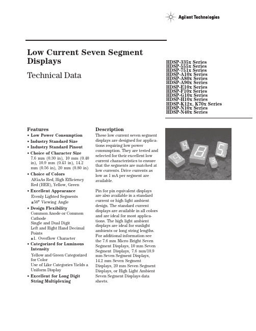
Features• Low Power Consumption • Industry Standard Size• Industry Standard Pinout • Choice of Character Size7.6 mm (0.30 in), 10 mm (0.40 in), 10.9 mm (0.43 in), 14.2 mm (0.56 in), 20 mm (0.80 in)• Choice of ColorsAlGaAs Red, High Efficiency Red (HER), Yellow, Green• Excellent Appearance Evenly Lighted Segments±50° Viewing Angle• Design FlexibilityCommon Anode or Common CathodeSingle and Dual DigitLeft and Right Hand Decimal Points±1. Overflow Character• Categorized for Luminous IntensityYellow and Green Categorized for ColorUse of Like Categories Yields a Uniform Display• Excellent for Long Digit String Multiplexing DescriptionThese low current seven segment displays are designed for applica-tions requiring low power consumption. They are tested and selected for their excellent low current characteristics to ensure that the segments are matched at low currents. Drive currents as low as 1 mA per segment are available.Pin for pin equivalent displays are also available in a standard current or high light ambient design. The standard current displays are available in all colors and are ideal for most applica-tions. The high light ambient displays are ideal for sunlight ambients or long string lengths. For additional information see the 7.6 mm Micro Bright Seven Segment Displays, 10 mm Seven Segment Displays, 7.6 mm/10.9 mm Seven Segment Displays, 14.2 mm Seven Segment Displays, 20 mm Seven Segment Displays, or High Light Ambient Seven Segment Displays data sheets.Low Current Seven SegmentDisplays Technical Data HDSP-335x SeriesHDSP-555x SeriesHDSP-751x SeriesHDSP-A10x Series HDSP-A80x Series HDSP-A90x Series HDSP-E10x Series HDSP-F10x Series HDSP-G10x Series HDSP-H10x Series HDSP-K12x, K70x Series HDSP-N10x SeriesHDSP-N40x SeriesDevicesAlGaAs HER Yellow Green Package HDSP-HDSP-HDSP-HDSP-Description Drawing A1017511A801A9017.6 mm Common Anode Right Hand Decimal A A1037513A803A9037.6 mm Common Cathode Right Hand Decimal B A1077517A807A9077.6 mm Common Anode ±1. Overflow C A1087518A808A9087.6 mm Common Cathode ±1. Overflow D F10110 mm Common Anode Right Hand Decimal E F10310 mm Common Cathode Right Hand Decimal F F10710 mm Common Anode ±1. Overflow G F10810 mm Common Cathode ±1. Overflow H G10110 mm Two Digit Common Anode Right Hand Decimal X G10310 mm Two Digit Common Cathode Right Hand Decimal Y E100335010.9 mm Common Anode Left Hand Decimal I E101335110.9 mm Common Anode Right Hand Decimal J E103335310.9 mm Common Cathode Right Hand Decimal K E106335610.9 mm Universal ±1. Overflow[1]L H101555114.2 mm Common Anode Right Hand Decimal M H103555314.2 mm Common Cathode Right Hand Decimal N H107555714.2 mm Common Anode ±1. Overflow O H108555814.2 mm Common Cathode ±1. Overflow P K121K70114.2 mm Two Digit Common Anode Right Hand Decimal R K123K70314.2 mm Two Digit Common Cathode Right Hand Decimal S N10020 mm Common Anode Left Hand Decimal Q N101N40120 mm Common Anode Right Hand Decimal T N103N40320 mm Common Cathode Right Hand Decimal U N10520 mm Common Cathode Left Hand Decimal V N106N40620 mm Universal ±1. Overflow[1]W Note:1. Universal pinout brings the anode and cathode of each segment’s LED out to separate pins. See internal diagrams L or W.Part Numbering System5082-x xx x-x x x xxHDSP-x xx x-x x x xxMechanical Options[1]00: No mechanical optionColor Bin Options[1,2]0: No color bin limitationMaximum Intensity Bin[1,2]0: No maximum intensity bin limitationMinimum Intensity Bin[1,2]0: No minimum intensity bin limitationDevice Configuration/Color[1]G: GreenDevice Specific Configuration[1]Refer to respective datasheetPackage[1]Refer to Respective datasheetNotes:1. For codes not listed in the figure above, please refer to the respective datasheet or contact your nearest Agilent representative fordetails.2. Bin options refer to shippable bins for a part-number. Color and Intensity Bins are typically restricted to 1 bin per tube (excep-tions may apply). Please refer to respective datasheet for specific bin limit information.Package DimensionsPackage Dimensions (cont.)Package Dimensions (cont.)*The Side View of package indicates Country of Origin.Package Dimensions (cont.)Package Dimensions (cont.)Package Dimensions (cont.)Internal Circuit DiagramInternal Circuit Diagram (cont.)Absolute Maximum RatingsAlGaAs Red - HDSP-HERA10X/E10X/H10X HDSP-751X/Yellow GreenK12X/N10X/N40X335X/555X/HDSP-A80X HDSP-A90X Description F10X, G10X Series K70X Series Series Series Units Average Power per Segment or DP375264mW Peak Forward Current per 45mA Segment or DPDC Forward Current per15[1]15[2]mA Segment or DPOperating Temperature Range-20 to +100-40 to +100°C Storage Temperature Range -55 to +100°C Reverse Voltage per Segment 3.0V or DPWave Soldering Temperature for 3Seconds (1.60 mm [0.063 in.] below 250°C seating body)Notes:1. Derate above 91°C at 0.53 mA/°C.2. Derate HER/Yellow above 80°C at 0.38 mA/°C and Green above 71°C at 0.31 mA/°C.Electrical/Optical Characteristics at T A = 25°CAlGaAs RedDeviceSeriesHDSP-Parameter Symbol Min.Typ.Max.Units Test Conditions315600I F = 1 mA A10x3600I F = 5 mA330650I F = 1 mAF10x, G10x3900I F = 5 mA390650I F = 1 mA E10x Luminous Intensity/Segment[1,2]I Vµcd(Digit Average)3900I F = 5 mA400700I F = 1 mAH10x, K12x4200I F = 5 mA270590I F = 1 mAN10x, N40x3500I F = 5 mA1.6I F = 1 mAForward Voltage/Segment or DP V F 1.7V I F = 5 mA1.82.2I F = 20 mA PkAll Devices Peak WavelengthλPEAK645nmDominant Wavelength[3]λd637nmReverse Voltage/Segment or DP[4]V R 3.015V I R = 100 µATemperature Coefficient of∆V F/°C-2 mV mV/°CV F/Segment or DPA10x255F10x, G10x320E10x340Thermal Resistance LED RθJ-PIN°C/W/SegH10x, K12x Junction-to-Pin400N10x, N40x430High Efficiency RedDeviceSeriesHDSP-Parameter Symbol Min.Typ.Max.Units Test Conditions160270I F = 2 mA 751x1050I F = 5 mA200300I F = 2 mA Luminous Intensity/Segment[1,2]I V mcd(Digit Average)1200I F = 5 mA335x, 555x,K70x270370I F = 2 mA1480I F = 5 mA1.6I F = 2 mAForward Voltage/Segment or DP V F 1.7V I F = 5 mA2.1 2.5I F = 20 mA Pk All Devices Peak WavelengthλPEAK635nmDominant Wavelength[3]λd626nmReverse Voltage/Segment or DP[4]V R 3.030V I R = 100 µATemperature Coefficient of∆V F/°C-2mV/°CV F/Segment or DP751x200335x Thermal Resistance LED RθJ-PIN280°C/WJunction-to-Pin555x, K70x345YellowDeviceSeriesHDSP-Parameter Symbol Min.Typ.Max.Units Test Conditions Luminous Intensity/Segment[1,2]250420I F = 4 mA(Digit Average)I V mcd1300I F = 10 mA1.7I F = 4 mAForward Voltage/Segment or DP V F 1.8V I F = 5 mA A80x2.1 2.5I F = 20 mA PkPeak WavelengthλPEAK583nmDominant Wavelength[3,5]λd581.5585592.5nmReverse Voltage/Segment or DP[4]V R 3.030V I R = 100 µATemperature Coefficient of∆V F/°C-2mV/°CV F/Segment or DPThermal Resistance LED RθJ-PIN200°C/WJunction-to-PinGreenDeviceSeriesHDSP-Parameter Symbol Min.Typ.Max.Units Test Conditions Luminous Intensity/Segment[1,2]250475I F = 4 mA(Digit Average)I V mcd1500I F = 10 mA1.9I F = 4 mAForward Voltage/Segment or DP V F 2.0V I F = 10 mA A90x2.1 2.5I F = 20 mA PkPeak WavelengthλPEAK566nmDominant Wavelength[3,5]λd571577nmReverse Voltage/Segment or DP[4]V R 3.030V I R = 100 µATemperature Coefficient of∆V F/°C-2mV/°CV F/Segment or DPThermal Resistance LED RθJ-PIN200°C/WJunction-to-PinNotes:1. Device case temperature is 25°C prior to the intensity measurement.2. The digits are categorized for luminous intensity. The intensity category is designated by a letter on the side of the package.3. The dominant wavelength, λd, is derived from the CIE chromaticity diagram and is the single wavelength which defines the color of thedevice.4. Typical specification for reference only. Do not exceed absolute maximum ratings.5. The yellow (HDSP-A800) and Green (HDSP-A900) displays are categorized for dominant wavelength. The category is designated by anumber adjacent to the luminous intensity category letter.Figure 1. Maximum AllowableAverage or DC Current vs. Ambient Temperature.Figure 2. Forward Current vs.Forward Voltage.AlGaAs RedFigure 4. Relative Efficiency (Luminous Intensity per UnitCurrent) vs. Peak Current.Figure 3. Relative Luminous Intensity vs. DC Forward Current.Figure 5. Maximum Allowable Average or DC Current vs. Ambient Temperature.Figure 6. Forward Current vs. Forward Voltage.HER, Yellow, GreenFigure 7. Relative Luminous Intensityvs. DC Forward Current.Figure 8. Relative Efficiency(Luminous Intensity per UnitCurrent) vs. Peak Current.Intensity Bin Limits (mcd)AlGaAs RedHDSP-A10xIV Bin Category Min.Max.E0.3150.520F0.4280.759G0.621 1.16H0.945 1.71I 1.40 2.56J 2.10 3.84K 3.14 5.75L 4.708.55HDSP-E10x/F10x/G10xIV Bin Category Min.Max.D0.3910.650E0.5320.923F0.755 1.39G 1.13 2.08H 1.70 3.14HDSP-H10x/K12xIV Bin Category Min.Max.C0.4150.690D0.5650.990E0.810 1.50F 1.20 2.20G 1.80 3.30H 2.73 5.00I 4.097.50HDSP-N10xIV Bin Category Min.Max.A0.2700.400B0.3250.500C0.4150.690D0.5650.990E0.810 1.50F 1.20 2.20G 1.80 3.30H 2.73 5.00I 4.097.50Intensity Bin Limits (mcd), continued HERHDSP-751xIV Bin Category Min.Max.B0.1600.240C0.2000.300D0.2500.385E0.3150.520F0.4280.759G0.621 1.16HDSP-751xIV Bin Category Min.Max.B0.2400.366C0.3000.477D0.3910.650E0.5320.923F0.755 1.39G 1.13 2.08H 1.70 3.14HDSP-555x/K70xIV Bin Category Min.Max.A0.2700.400B0.3250.500C0.4150.690D0.5650.990E0.810 1.50F 1.20 2.20G 1.80 3.30H 2.73 5.00I 4.097.50Intensity Bin Limits (mcd), continued YellowHDSP-A80xIV Bin Category Min.Max.D0.2500.385E0.3150.520F0.4250.760G0.625 1.14H0.940 1.70I 1.40 2.56J 2.10 3.84K 3.14 5.76L 4.718.64M7.0713.00N10.6019.40O15.9029.20P23.9043.80Q35.8065.60GreenHDSP-A90xIV Bin Category Min.Max.E0.3150.520F0.4250.760G0.625 1.14H0.940 1.70I 1.40 2.56J 2.10 3.84K 3.14 5.76L 4.718.64M7.0713.00N10.6019.40O15.9029.20P23.9043.80Q35.8065.60Electrical/OpticalFor more information on electrical/optical characteristics, please see Application Note 1005.Contrast Enhancement For information on contrast enhancement, please see Application Note 1015.Soldering/Cleaning Cleaning agents from the ketone family (acetone, methyl ethyl ketone, etc.) and from the chorinated hydrocarbon family (methylene chloride, trichloro-ethylene, carbon tetrachloride, etc.) are not recommended for cleaning LED parts. All of these various solvents attack or dissolve the encapsulating epoxies used to form the package of plastic LED parts.For information on soldering LEDs, please refer to Application Note 1027.Note:All categories are established for classification of products. Productsmay not be available in all categories. Please contact your localAgilent representatives for further clarification/information.Color Categories/semiconductorsFor product information and a complete list ofdistributors, please go to our web site.For technical assistance call:Americas/Canada: +1 (800) 235-0312 or(916) 788 6763Europe: +49 (0) 6441 92460China: 10800 650 0017Hong Kong: (+65) 6271 2451India, Australia, New Zealand: (+65) 6271 2394Japan: (+81 3) 3335-8152(Domestic/International), or0120-61-1280(Domestic Only)Korea: (+65) 6271 2194Malaysia, Singapore: (+65) 6271 2054Taiwan: (+65) 6271 2654Data subject to change.Copyright © 2005 Agilent Technologies, Inc.Obsoletes 5988-8412ENJanuary 19, 20055989-0080EN。
2SC5551中文资料

Package Dimensions
unit:mm 2038A
[2SC5551]
4.5 1.6 1.5
0.5 3 1.5 2 3.0 0.75 1
1.0
0.4
2.5 4.25max
0.4
Specifications
Absolute Maximum Ratings at Ta = 25˚C
Parameter Collector-to-Base Voltage Collector-to-Emitter Voltage Emitter-to-Base Voltage Collector Current Collector Current (pulse) Collector Dissipation Junction Temperature Storage Temperature Symbol VCBO VCEO VEBO IC ICP PC Tj Tstg Mounted on a ceramic board (250mm2× 0.8mm) Conditions
VCE=5V, IC=1mA, ZO=50Ω
Freq (MHz) 100 200 300 400 500 600 700 800 900 1000 | S11 | 0.941 0.859 0.829 0.831 0.840 0.816 0.816 0.814 0.800 0.804 ∠ S11 –101.1 –141.0 –158.6 –169.5 –178.6 172.3 164.9 157.3 150.9 145.0 | S21 | 2.373 1.425 0.990 0.845 0.715 0.638 0.507 0.466 0.443 0.388 ∠ S21 119.9 93.8 79.4 69.2 61.1 54.7 49.8 47.0 45.7 47.3 | S12 | 0.088 0.097 0.088 0.074 0.058 0.055 0.064 0.098 0.134 0.173 ∠ S12 38.7 18.3 12.0 10.7 25.2 51.6 78.4 87.3 90.2 92.2 | S22 | 0.884 0.821 0.755 0.766 0.798 0.790 0.771 0.813 0.792 0.782 ∠ S22 –17.8 –25.2 –33.8 –41.9 –49.9 –58.4 –66.7 –75.0 –82.8 –90.0
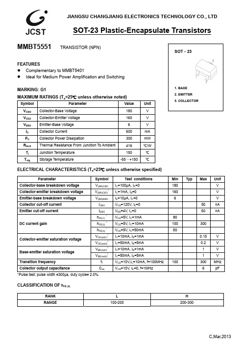
MMBT5551中文资料_数据手册_参数
10
100
200
COLLECTOR CURRENT I (mA) C
C / C ——
ob
ib
V /V
CB
EB
C ib
f=1MHz
I =0 / I =0
E
C
T =25℃ a
C ob
COLLECTOR CURRENT I (mA) C
TRANSITION FREQUENCY f (MHz) T
1
0.2
0.4
180 160
6 600 300 416 150 -55~+150
Unit V V V mA
mW ℃/W
℃ ℃
ELECTRICAL CHARACTERISTICS (Ta=25℃ unless otherwise specified)
Parameter
Symbol
Collector-base breakdown voltage Collector-emitter breakdown voltage
C,Mar,2013
Typical Characteristics
MMBT5551
COLLECTOR CURRENT I (mA) C
Static Characteristic
18
90uA
COMMON
EMITTER
15
80uA T =25℃
a
70uA
12
60uA
50uA
9
40uA
6
30uA
I =20uA
IEBO hFE(1) * hFE(2) * hFE(3) * VCE(sat)1* VCE(sat)2* VBE(sat)1* VBE(sat)2*
555芯片资料

NE555YCHIP FORM(Y)NE555, NE555Y, SA555, SE555, SE555CPRECISION TIMERSCopyright 1991, Texas Instruments IncorporatedNE555, NE555Y, SA555, SE555, SE555C PRECISION TIMERSSLFS022 – D1669, SEPTEMBER 1973—REVISED FEBRUARY 1992NE555YPRECISION TIMERSSLFS022 – D1669, SEPTEMBER 1973—REVISED FEBRUARY 1992UNITSLFS022 – D1669, SEPTEMBER 1973—REVISED FEBRUARY 1992NE555, SA555, SE555, SE555C PRECISION TIMERSTHRES voltage levelTRIG voltage levelRESET currentCONT voltage (open circuit)Low-level output voltage Supply current V CC = 15 VV CC = 5 VV CC = 15 VOutput low, No loadOutput high, No loadVVmAVVVTESTCONDITIONS†Initial error of timing interval‡T A = 25°CT A = MIN to MAX T A = 25°Cppm/°C%/Vns SLFS022 – D1669, SEPTEMBER 1973—REVISED FEBRUARY 1992 NE555, SA555, SE555, SE555CPRECISION TIMERSTHRES voltage level TRIG voltage levelRESET current CONT voltage (open circuit)Low-level output voltageSupply currentV CC = 15 VV CC = 5 V V CC = 15 VOutput low, No loadOutput high, No loadVVmAVVVInitial error of timing interval †%/V nsC L = 15 pFSupply voltage sensitivity of timing intervalSLFS022 – D1669, SEPTEMBER 1973—REVISED FEBRUARY 1992NE555YPRECISION TIMERSNE555, SA555, SE555, SE555CPRECISION TIMERSSLFS022 – D1669, SEPTEMBER 1973—REVISED FEBRUARY 1992NE555, SA555, SE555, SE555C PRECISION TIMERSSLFS022 – D1669, SEPTEMBER 1973—REVISED FEBRUARY 1992NE555, SA555, SE555, SE555CPRECISION TIMERSSLFS022 – D1669, SEPTEMBER 1973—REVISED FEBRUARY 1992NE555, SA555, SE555, SE555C PRECISION TIMERSSLFS022 – D1669, SEPTEMBER 1973—REVISED FEBRUARY 1992NE555, SA555, SE555, SE555CPRECISION TIMERSSLFS022 – D1669, SEPTEMBER 1973—REVISED FEBRUARY 1992NE555, SA555, SE555, SE555C PRECISION TIMERSSLFS022 – D1669, SEPTEMBER 1973—REVISED FEBRUARY 1992NE555, SA555, SE555, SE555CPRECISION TIMERSSLFS022 – D1669, SEPTEMBER 1973—REVISED FEBRUARY 1992NE555, SA555, SE555, SE555C PRECISION TIMERSSLFS022 – D1669, SEPTEMBER 1973—REVISED FEBRUARY 1992IMPORTANT NOTICETexas Instruments (TI) reserves the right to make changes to its products or to discontinue any semiconductor product or service without notice, and advises its customers to obtain the latest version of relevant information to verify, before placing orders, that the information being relied on is current.TI warrants performance of its semiconductor products and related software to the specifications applicable at the time of sale in accordance with TI’s standard warranty. Testing and other quality control techniques are utilized to the extent TI deems necessary to support this warranty. Specific testing of all parameters of each device is not necessarily performed, except those mandated by government requirements.Certain applications using semiconductor products may involve potential risks of death, personal injury, or severe property or environmental damage (“Critical Applications”).TI SEMICONDUCTOR PRODUCTS ARE NOT DESIGNED, INTENDED, AUTHORIZED, OR WARRANTED TO BE SUITABLE FOR USE IN LIFE-SUPPORT APPLICATIONS, DEVICES OR SYSTEMS OR OTHER CRITICAL APPLICATIONS.Inclusion of TI products in such applications is understood to be fully at the risk of the customer. Use of TI products in such applications requires the written approval of an appropriate TI officer. Questions concerning potential risk applications should be directed to TI through a local SC sales office.In order to minimize risks associated with the customer’s applications, adequate design and operating safeguards should be provided by the customer to minimize inherent or procedural hazards.TI assumes no liability for applications assistance, customer product design, software performance, or infringement of patents or services described herein. Nor does TI warrant or represent that any license, either express or implied, is granted under any patent right, copyright, mask work right, or other intellectual property right of TI covering or relating to any combination, machine, or process in which such semiconductor products or services might be or are used.Copyright © 1995, Texas Instruments Incorporated。
2N5551中文数据手册

10 1
0.3
β=10
0.1
10
100
200
COLLECTOR CURRENT I (mA) C
V —— I
CEsat
C
T =100℃ a T =25℃ a
0.01 1
100
10
10
100
200
C / C ——
ob
ib
V /V
CB
EB
C ib
f=1MHz
Min Typ Max Unit
180
V
160
V
6
V
50
nA
50
nA
80
80
300
50
0.15
V
0.2
V
1
V
1
V
6
pF
20
pF
100
300 MHz
C 200-300
B,Jun,2012
典型特征
(mA)
I
C
集电极电流
Static Characteristic
18
90uA
COMMON
EMITTER
15
TO – 92
1. 发射极 E 2. 基极 B 3. 集电极 C
值 180 160
6 0.6 625 200 150 -55~+150
单位 V V V A
mW ℃/W
℃ ℃
电气特性 (Ta=25℃ 除非另有说明)
参数
符号
测试条件
C-B极间击穿电压 C-E极间击穿电压
V(BR)CBO V(BR)CEO*
江苏长江电子技术股份有限公司
TO-92 塑料封装晶体管
2N5551中文资料_数据手册_参数

Packing Method Ammo
Tape and Reel Tape and Reel
Bulk Tape and Reel
© 2009 Fairchild Semiconductor Corporation
Top Mark 5551 5551 5551 5551 3S
Package TO-92 3L TO-92 3L TO-92 3L TO-92 3L SOT-23 3L
Note: 1. Suffix “-C” means Center Collector in 2N5551 (1. Emitter 2. Collector 3. Base)
Symbol
Parameter
Value
Units
VCEO VCBO VEBO
IC TJ, Tstg(2)
Collector-Emitter Voltage Collector-Base Voltage Emitter-Base Voltage Collector current - Continuous Junction and Storage Temperature
2N5551 / MMBT5551 Rev. 1.1.0
1
2N5551 / MMBT5551 — NPN General-Purpose Amplifier
Absolute Maximum Ratings(2)
Stresses exceeding the absolute maximum ratings may damage the device. The device may not function or be operable above the recommended operating conditions and stressing the parts to these levels is not recommended. In addition, extended exposure to stresses above the recommended operating conditions may affect device reliability. The absolute maximum ratings are stress ratings only. Values are at TA = 25°C unless otherwise noted.
5551定时器
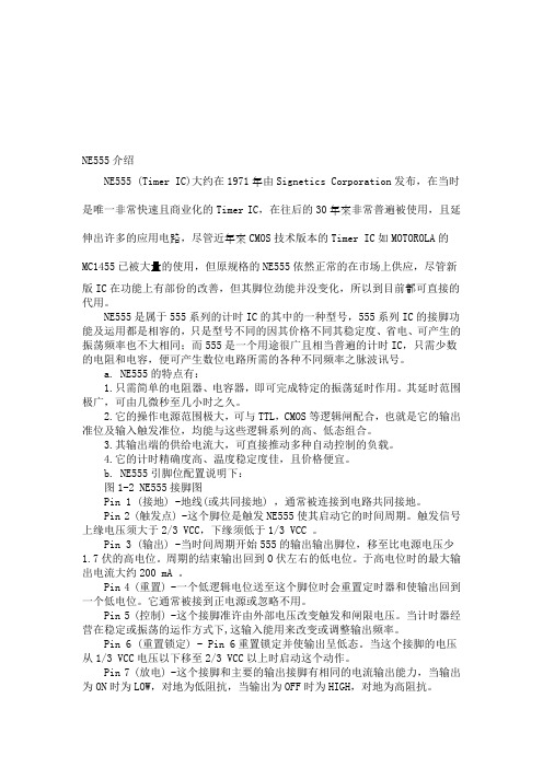
NE555介绍NE555 (Timer IC)大约在1971年由Signetics Corporation发布,在当时是唯一非常快速且商业化的Timer IC,在往后的30年來非常普遍被使用,且延伸出许多的应用电路,尽管近年來CMOS技术版本的Timer IC如MOTOROLA的MC1455已被大量的使用,但原规格的NE555依然正常的在市场上供应,尽管新版IC在功能上有部份的改善,但其脚位劲能并没变化,所以到目前都可直接的代用。
NE555是属于555系列的计时IC的其中的一种型号,555系列IC的接脚功能及运用都是相容的,只是型号不同的因其价格不同其稳定度、省电、可产生的振荡频率也不大相同;而555是一个用途很广且相当普遍的计时IC,只需少数的电阻和电容,便可产生数位电路所需的各种不同频率之脉波讯号。
a. NE555的特点有:1.只需简单的电阻器、电容器,即可完成特定的振荡延时作用。
其延时范围极广,可由几微秒至几小时之久。
2.它的操作电源范围极大,可与TTL,CMOS等逻辑闸配合,也就是它的输出准位及输入触发准位,均能与这些逻辑系列的高、低态组合。
3.其输出端的供给电流大,可直接推动多种自动控制的负载。
4.它的计时精确度高、温度稳定度佳,且价格便宜。
b. NE555引脚位配置说明下:图1-2 NE555接脚图Pin 1 (接地) -地线(或共同接地) ,通常被连接到电路共同接地。
Pin 2 (触发点) -这个脚位是触发NE555使其启动它的时间周期。
触发信号上缘电压须大于2/3 VCC,下缘须低于1/3 VCC 。
Pin 3 (输出) -当时间周期开始555的输出输出脚位,移至比电源电压少1.7伏的高电位。
周期的结束输出回到O伏左右的低电位。
于高电位时的最大输出电流大约200 mA 。
Pin 4 (重置) -一个低逻辑电位送至这个脚位时会重置定时器和使输出回到一个低电位。
它通常被接到正电源或忽略不用。
SA555

tr tf toff
Notes :
5. No protection against excessive Pin 7 current is necessary, providing the package dissipation rating will not be exceeded. 6. Time mesaured from a positive going input pulse from 0 to 0.8x VCC into the threshold to the drop from high to low of the output trigger is tied to treshold.
®
NE555 SA555 - SE555
GENERAL PURPOSE SINGLE BIPOLAR TIMERS
. . . . . . . .
LOW TURN OFF TIME MAXIMUM OPERATING FREQUENCY GREATER THAN 500kHz TIMING FROM MICROSECONDS TO HOURS OPERATES IN BOTH ASTABLE AND MONOSTABLE MODES HIGH OUTPUT CURRENT CAN SOURCE OR SINK 200mA ADJUSTABLE DUTY CYCLE TTL COMPATIBLE TEMPERATURE STABILITY OF 0.005% PERoC
RES ET DISCHARGE
4 7 Q14
Q15 Q17 R5 10kΩ R6 100kΩ R7 100kΩ
R10 5kΩ
G ND
1
TRIGGER COMPARATOR
2N5551中文资料(Unisonic Technologies)中文数据手册「EasyDatasheet - 矽搜」
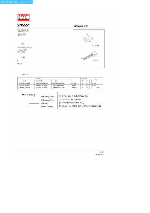
无卤
2N5551G-x-AB3-R 2N5551G-x-T92-B 2N5551G-x-T92-K
包
SOT-89 TO-92 TO-92
引脚分配
12 BC EB EB
填料
3 Ë带卷轴 Ç磁带盒 C Bulk
QW-R201-002.C
芯片中文手册,看全文,戳
2N5551
典型特征
集电极输出电容
10
8
f=1MHz
I =0
6
4 2
0
10
10
10
集电极基极电压(V)
NPN硅晶体管
DC电流增益 10
V =5V
10
10
10 10
10 10 集电极电流,I
10 10 (mA)
(mA) 集电极电流,I
4之1
QW-R201-002.C
芯片中文手册,看全文,戳
2N5551
NPN硅晶体管
绝对最大额定值
(TA = 25℃,除非另有规定)
参数
集电极基极电压
集电极 - 发射极电压
发射极基极电压
集电极耗散
TO-92
集电极耗散
SOT-89
集电极电流
结温
储存温度
注意:绝对最大额定值是那些超出该装置可以永久损坏值.
4 of 4
QW-R201-002.C
芯片中文手册,看全文,戳
2N5551
高压开关 晶体管
特征 *高集电极 - 发射极电压:
VCEO=160V *高电流增益
应用
* *放大器
NPN硅晶体管
SZ产品手册版

星型网
LINE_1
链型网 ID=1
LINE_2
链型网 ID=2
LINE_3
链型网 ID=3
LINE_4
链型网 ID=4
PEER
对等网
非主从网,无中心节点。
4.3
PAN_Coord
中心节点
网络中必须有一个中心节点。
ROUTER
中继路由
兼有终端设备功能。
END_DEVICE
终端设备
SZ05-ZBEE无线通信模块有三种节点类型:中心节点、中继路由、终端节点,通过跳线短接的方式来控制中心接点、中继路由或终端节点的设置,跳线短接有效,中心节点或终端节点的跳线选择只能选其一,如果两个跳线都悬空,则设置为中继路由节点。
3.8
SZ05-ZBEE无线通信模块CONFIG跳线短接或外部控制线进入低电平状态3秒,系统进入配置状态;高电平或悬空状态则进入工作状态。
配置接口是用于对本产品的某些参数进行配置的接口,串口信号为RS232默认配置如下。
串口速率
38400
串口校验
None
数据位
8
停止位
1
配置接口设置
SZ05-ZBEE无线通信模块的配置模式可以分为超级终端配置模式、计算机网管配置模式,两种模式的状态区分如下:
RS-232串口为TX、RX、GND三线工作模式;TTL为TX、RX2线工作模式,TTL电平为3.3V。
系统默认的数据接口参数:
串口速率
9600
串口校验
None
数据位
8
停止位
1
数据接口默认设置
3.7
SZ05-ZBEE无线通信模块有三种节点类型:中心节点、中继路由、终端节点,通过跳线短接的方式来控制中心接点、中继路由或终端节点的设置,跳线短接有效,中心节点或终端节点的跳线选择只能选其一,如果两个跳线都悬空,则设置为中继路由节点。
555芯片详细资料
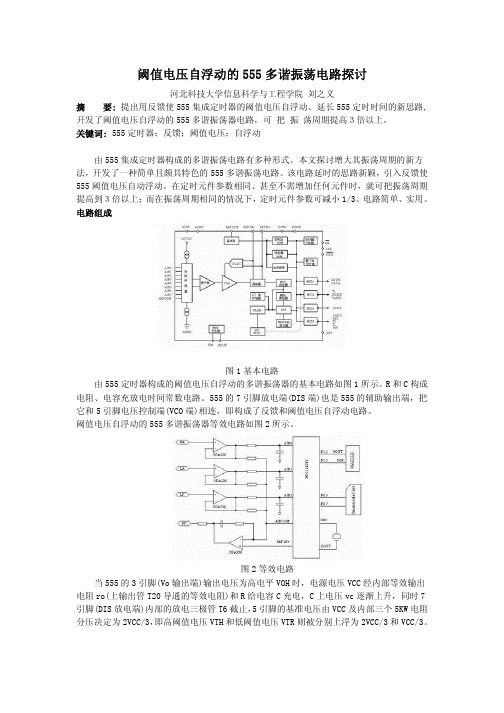
阈值电压自浮动的555多谐振荡电路探讨河北科技大学信息科学与工程学院 刘之义摘 要: 提出用反馈使555集成定时器的阈值电压自浮动、延长555定时时间的新思路,开发了阈值电压自浮动的555多谐振荡器电路,可 把 振 荡周期提高3倍以上。
关键词: 555定时器;反馈;阈值电压;自浮动由555集成定时器构成的多谐振荡电路有多种形式。
本文探讨增大其振荡周期的新方法,开发了一种简单且颇具特色的555多谐振荡电路。
该电路延时的思路新颖,引入反馈使555阈值电压自动浮动。
在定时元件参数相同、甚至不需增加任何元件时,就可把振荡周期提高到3倍以上;而在振荡周期相同的情况下,定时元件参数可减小1/3。
电路简单、实用。
电路组成图1基本电路由555定时器构成的阈值电压自浮动的多谐振荡器的基本电路如图1所示。
R和C构成电阻、电容充放电时间常数电路。
555的7引脚放电端(DIS端)也是555的辅助输出端,把它和5引脚电压控制端(VCO端)相连,即构成了反馈和阈值电压自浮动电路。
阈值电压自浮动的555多谐振荡器等效电路如图2所示。
图2等效电路当555的3引脚(Vo输出端)输出电压为高电平VOH时,电源电压VCC经内部等效输出电阻ro(上输出管T20导通的等效电阻)和R给电容C充电,C上电压vc逐渐上升,同时7引脚(DIS放电端)内部的放电三极管T6截止,5引脚的基准电压由VCC及内部三个5KW电阻分压决定为2VCC/3,即高阈值电压VTH和低阈值电压VTR则被分别上浮为2VCC/3和VCC/3。
故当vc被充电到大于2VCC/3时,由555功能知,vo输出端3引脚电压跳变为低电平VOL,同时7引脚(DIS放电端)内部的放电三极管T6导通。
一方面,电容C上的电压vc经R和输出端3引脚内部导通的下输出管T21对地放电,C上电压vc逐渐下降。
另一方面,5引脚的(控制电压)基准电压VCO即被下拉到三极管T6的饱和压降值VCES,而使两个阈值电压分别下浮为VTH=VCES和VTR=VCES/2。
555定时器芯片的特点介绍

555定时器芯片的特点介绍555定时器芯片的特点介绍555定时器芯片的特点555时基电路具有以下几个特点:(1)555时基电路,是一种将模拟电路和数字电路巧妙结合在一起的电路;(2)555时基电路可以采用4.5~15V的单独电源,也可以和其它的运算放大器和TTL电路共用电源;(3)一个单独的555时基电路,可以提供近15分钟的较准确的定时时间;(4)555时基电路具有一定的输出功率,最大输出电流达200mA,可直接驱动继电器、小电动机、指示灯及喇叭等负载。
因此,555时基电路可用作:脉冲发生器、方波发生器、单稳态多谐振荡器、双稳态多谐振荡器、自由振荡器、内振荡器、定时电路、延时电路、脉冲调制电路、仪器仪表的各种控制电路及民用电子产品、电子琴、电子玩具等。
现以5G1555时基集成电路为例,说明其各脚功能。
5G1555时基电路有两种结构。
一种为金属圆壳封装(型号为5G1555),其外貌与管脚排列如图39-1中(a)所示;另一种为陶瓷双列封装(型号为5G1555C),其外貌与管脚排列如图39-1中(b)及上图所示。
图39-1无论是进口或国产的时基555集成电路,还是用何种材料封装,其内部电路原理和管脚的功能则是完全一致的。
其各管脚功能如下:①脚接电源地线,即电源的负极;②脚为低电位触发端,简称低触发端;③脚为输出端,可将继电器、小电动机及指示灯等负载的一端与它相连,另一端接地或电源的正极;④脚为低电位复位端;⑤脚为电压控制端,主要是用来调节比较器的触发电位;⑤脚为高电位触发端,简称高触发端;⑦脚为放电端;⑧脚接电源正极。
弄清各管脚的功能后,正确运用555时基集成电路就十分容易了。
5551 晶体管芯片说明书

参数符号
符号说明
ICBO
集电极—基极截止电流
IEBO
发射极—基极截止电流
hFE
直流电流增益
VCE(sat) 集电极—发射极饱和电压
VBE(sat) 基极—发射极饱和电压
BVCBO BVCEO BVEBO fT
集电极—基极击穿电压 集电极—发射极击穿电压 发射极—基极击穿电压 特征频率
最小值 典型值 最大值 单 位 测 试 条 件
0.05 µA VCB=120V,IE=0
0.05 µA VEB=4V,IC=0
80
VCE=5V,IC=1mA
80
280
VCE=5V,IC=10mA
30
VCE=5V,IC=50mA
0.15
V IC=10mA,IB=1mA
0.2
V IC=50mA,IB=5mA
1
V IC=10mA,IB=1mA
1
V IC=50mA,IB=5mA
180
V IC=100µA,IE=0
160
V IC=1mA,IB=0
6
V IE=10µA,IC=0
100
300 MHz VCE=10V,IC=10mA图
█ 极限值(Ta=25℃)(封装形式:TO-92)
Tstg——贮存温度…………………………………… -55~150℃ Tj——结温…………………………………………………150℃ PC——集电极耗散功率…………………………………625mW VCBO——集电极—基极电压………………………………180V VCEO——集电极—发射极电压……………………………160V VEBO——发射极—基极电压…………………………………6V IC——集电极电流…………………………………………600mA
555芯片

TS555C,I,MLOW POWER SINGLE CMOS TIMERSJanuary 1999.VERY LOW POWER CONSUMPTION :.100µA typ at V CC =5V.HIGH MAXIMUM ASTABLE FREQUENCY 2.7MHz.PIN-TO-PIN AND FUNCTIONALLY COMPATIBLE WITH BIPOLAR NE555.VOLTAGE RANGE :+2V to +18V.HIGH OUTPUT CURRENT CAPABILITY.SUPPLY CURRENT SPIKES REDUCED DURING OUTPUT TRANSITIONS .HIGH INPUT IMPEDANCE :1012Ω.OUTPUT COMPATIBLE WITH TTL,CMOS AND LOGIC MOSN DIP8(Plastic Package)D SO8(Plastic Micropackage)12348765GND Trigger Output ResetCC Control VoltageV Discharge Threshold PIN CONNECTIONS (top view)ORDER CODESPart Number TemperatureRange Package NDPTS555C 0oC,+70oC q q q TS555I -40,+125oC q q q TS555M-55,+125o CqqqExamples :TS555CD ,TS555IN®DESCRIPTIONThe TS555is a single CMOS timer which offers very low consumption (Icc (TYP)TS555=100µA Icc (TYP)NE555=3mA)and high frequency(f (max.)TS555=2.7MHz -f (max.)NE555=0.1MHz)Thus,either in Monostable or Astable mode,timing remains very accurate.The TS555provides reduced supply current spikes during output transitions,which enables the use of lower decoupling capacitors compared to those required by bipolar NE555.Timing capacitors can also be minimized due to high input impedance (1012Ω).P TSSOP8(Thin Shrink Small Outline Package)1/12RESET TRIGGERTHRESHOLDOUTPUT Low x x Low High Low x High High High High Low High HighLowPrevious StateLOW £Level Voltage ≤Min voltage specified HIGH £Level Voltage ≥Max voltage specified X£IrrelevantABSOLUTE MAXIMUM RATINGSSymbol ParameterValue Unit V CC Supply Voltage +18VT JJunction Temperature+150oCTHERMAL CHARACTERISTICSSymbol ParameterValue UnitT OPEROperating Temperature RangeTS555C TS555I TS555M 0to +70-40to +125-55to +125oCT STG Storage Temperature Range-65to +150oCOutputDis chargeGroundTr igger ControlVol tageThres hold V CCR eset165284RRRBAR1RSQ +-+-73TS555BLOCK DIAGRAMTS555C,I,M2/12R 150k ΩΤ1R 250k ΩR 350k ΩR 450kΩR 550kΩR 650kΩΤ2Τ4T h r e s h o l dΤ5Τ6Τ7Τ14Τ8Τ9Τ15Τ16Τ17Τ18Τ19T r i g g e rΤ24Τ22Τ23Τ28Τ29Τ32Τ35Τ33D i s c h a r g eO u t p u tΤ10Τ11Τ12Τ13Τ20Τ21Τ26Τ25Τ27Τ30Τ31Τ34G N D R E S E TVC CR 7C o n t r o l V o l t a g eSCHEMATIC DIAGRAMTS555C,I,M3/12STATIC ELECTRICAL CHARACTERISTICSV CC =+2V,T amb =+25o C,Reset to V CC (unless otherwise specified)Symbol ParameterTS555C-TS555I-TS555M UnitMin.Typ Max.I CCSupply Current (no load,High and Low States)T amb =+25oCT min .≤T amb ≤T max .65200200µAV CLControl VoltageT amb =+25o CT min .≤T amb ≤T max .1.21.11.31.41.5VV disDischarge Saturation Voltage (I dis =1mA)T amb =+25o CT min .≤T amb ≤T max .0.050.20.25VV OLLow Level Output Voltage (I sink =1mA)T amb =+25oCT min .≤T amb ≤T max .0.10.30.35VV OHHigh Level Output Voltage (I source =-0.3mA)T amb =+25o CT min .≤T amb ≤T max . 1.51.5 1.9VV trigTrigger VoltageT amb =+25oCT min .≤T amb ≤T max .0.40.30.670.951.05VI trig Trigger Current 10pA I TH Threshold Current 10pAV resetReset VoltageT amb =+25oCT min .≤T amb ≤T max .0.40.3 1.1 1.52.0VI reset Reset Current10pA I disDischarge Pin Leakage Current1100nAOPERATING CONDITIONSSymbol ParameterValue Unit V CCSupply Voltage+2to +16VTS555C,I,M4/12STATIC ELECTRICAL CHARACTERISTICS(continued)V CC=+5V,T amb=+25o C,Reset to V CC(unless otherwise specified)Symbol Parameter TS555C-TS555I-TS555MUnit Min.Typ Max.I CC Supply Current(no load,High and Low States)T amb=+25o CT min.≤T amb≤T max.110250250µAV CL Control VoltageT amb=+25o CT min.≤T amb≤T max.2.92.83.3 3.83.9VV dis Discharge Saturation Voltage(I dis=10mA) T amb=+25o CT min.≤T amb≤T max.0.20.30.35VV OL Low Level Output Voltage(I sink=8mA)T amb=+25o CT min.≤T amb≤T max.0.30.60.8VV OH High Level Output Voltage(I source=-2mA) T amb=+25o CT min.≤T amb≤T max.4.44.44.6VV trig Trigger VoltageT amb=+25o CT min.≤T amb≤T max.1.361.261.67 1.962.06VI trig Trigger Current10pA I TH Threshold Current10pAV reset Reset VoltageT amb=+25o CT min.≤T amb≤T max.0.40.31.1 1.52.0VI reset Reset Current10pAI dis Discharge Pin Leakage Current1100nATS555C,I,M5/12STATIC ELECTRICAL CHARACTERISTICS(continued)V CC=+12V,T amb=+25o C,Reset to V CC(unless otherwise specified)Symbol Parameter TS555C-TS555I-TS555MUnit Min.Typ Max.I CC Supply Current(no load,High and Low States)T amb=+25o CT min.≤T amb≤T max.170400400µAV CL Control VoltageT amb=+25o CT min.≤T amb≤T max.7.47.388.68.7VV dis Discharge Saturation Voltage(I dis=80mA) T amb=+25o CT min.≤T amb≤T max.0.09 1.62.0VV OL Low Level Output Voltage(I sink=50mA)T amb=+25o CT min.≤T amb≤T max.1.222.8VV OH High Level Output Voltage(I source=-10mA) T amb=+25o CT min.≤T amb≤T max.10.510.511VV trig Trigger VoltageT amb=+25o CT min.≤T amb≤T max.3.23.14 4.84.9VI trig Trigger Current10pA I TH Threshold Current10pAV reset Reset VoltageT amb=+25o CT min.≤T amb≤T max.0.40.31.1 1.52.0VI reset Reset Current10pAI dis Discharge Pin Leakage Current1100nA TS555C,I,M6/12DYNAMIC ELECTRICAL CHARACTERISTICST amb=+25o C,Reset to V CC(unless otherwise specified)Symbol Parameter TS555C-TS555I-TS555MUnit Min Typ MaxTiming Accuracy(Monostable)-(note1)R=10kΩ,C=0.1µFV CC=+2VV CC=+5VV CC=+12V 124%Timing Shift with supply voltage variations(Monostable)R=10kΩ,C=0.1µF,V CC=+5V+/-1V0.38%/VTiming Shift with temperatureT min.≤T amb≤T max.,V CC=+5V75ppm/°Cf max Maximum astable frequencyR A=470Ω,R B=200Ω, C=200pF,V CC=+5V 2.7MHz Astable frequency accuracy-(note2)R A=R B=1kΩto100kΩ,C=0.1µFV CC=+5VV CC=+12V 33%Timing Shift with supply voltage variations(Astable mode)R A=R B=1kΩto100kΩ,C=0.1µF,V CC=5to+12V0.1%/V t r Output Rise Time(V CC=+5V,C load=10pF)25nst f Output Fall Time(V CC=+5V,C load=10pF)20-ns t pd Trigger Propagation Delay(V CC=+5V)100ns t rpw Minimum Reset Pulse Width(V trig=+5V)350nsNotes:1.See Figure22.See Figure4TS555C,I,M7/12APPLICATION INFORMATION MONOSTABLE OPERATIONIn the monostable mode,the timer functions as a one-shot.Referring to figure 2the external capaci-tor is initially held discharged by a transistor inside the timer.V CCResetTriggerOut32487651TS555RCControl Voltage0.01FµFigure 2CC SUPPLY VOLTAGE,V (V)C C S U P P L Y C U R R E N T ,I (A )µ3002001000481216TYPICAL CHARACTERISTICSFigure 1:Supply Current (each timer)versusSupply VoltageThe circuit triggers on a negative-goinginput signal when the level reaches 1/3V CC .Oncetriggered,the circuit remains in this state until the set time has elapsed,even if it is triggered again during this interval.The duration of the output HIGH state is given by t =1.1R x C.Notice that since the charge rate and the threshold level of the comparator are both directly propor-tional to supply voltage,the timing interval is inde-pendent of supply.Applying a negative pulse simultaneouslyto the Reset terminal (pin 4)and the Trigger terminal (pin 2)during the timing cycle discharges the external capacitor and causes the cycle to start over.The timing cycle now starts on the positive edge of the reset pulse.During the time the reset pulse is applied,the output is driven to its LOW state.When a negative trigger pulse is applied to pin 2,the flip-flop is set,releasing the short circuit across the external capacitor and driving the output HIGH.The voltage across the capacitor increases expo-nentially with the time constant τ=R x C.When the voltage across the capacitor equals 2/3V CC ,the comparator resets the flip-flop which then discharges the capacitor rapidly and drives the output to its LOW state.Figure 3shows the actual waveforms generatedin this mode of operation.When Reset is not used,it should be tied high to avoid any possible or false triggering.CAPACITOR VOLTAGE =2.0V/div ΩΩµt =0.1ms /div INPUT =2.0V/divOUTPUT VOLTAGE =5.0V/divR =9.1k ,C =0.01F ,R =1.0k L Figure 3TS555C,I,M8/12ASTABLE OPERATIONWhen the circuit is connected as shown in figure 4(pin 2and 6connected)it triggers itself and free runs as a multivibrator.The external capacitor charges through R A a n d R B and discharges through R B only.Thus the duty cycle may be pre-cisely set by the ratio of these two resistors.In the astable mode of operation,C charges and discharges between 1/3V CC and 2/3V CC .As in the triggered mode,the charge and discharge times and therefore frequency,are independent of the supply voltage.Figure 5shows actual waveforms generated in this mode of operation.The charge time (output HIGH)is given by :t1=0.693(R A +R B )Cand the discharge time (output LOW)by :t2=0.693(R B )CThus the total period T is given by :T =t1+t2=0.693(R A +2R B )C The frequency of oscillation is then :f =1T =1.44(R A +2R B )C The duty cycle is given by :D =R BR A +2R BV CCResetOut348751TS555R C26R ABControl Voltage 0.01FµFigure 4ΩΩµt =0.5ms /divOUTPUT VOLTAGE =5.0V/divCAPACITOR VOLTAGE =1.0V/divL R =R =4.8k ,C =0.1F ,R =1.0k A BFigure 5TS555C,I,M9/12PACKAGE MECHANICAL DATA 8PINS-PLASTIC DIPDimensionsMillimeters InchesMin.Typ.Max.Min.Typ.Max.A 3.320.131a10.510.020B 1.15 1.650.0450.065b0.3560.550.0140.022 b10.2040.3040.0080.012 D10.920.430 E7.959.750.3130.384e 2.540.100e37.620.300e47.620.300F 6.60260i 5.080.200L 3.18 3.810.1250.150 Z 1.520.060 TS555C,I,M10/12PACKAGE MECHANICAL DATA8PINS-PLASTIC MICROPACKAGE(SO)DimensionsMillimeters InchesMin.Typ.Max.Min.Typ.Max.A 1.750.069a10.10.250.0040.010a2 1.650.065a30.650.850.0260.033b0.350.480.0140.019b10.190.250.0070.010C0.250.50.0100.020c145o(typ.)D 4.8 5.00.1890.197E 5.8 6.20.2280.244e 1.270.050e3 3.810.150F 3.8 4.00.1500.157L0.4 1.270.0160.050M0.60.024S8o(max.)TS555C,I,M11/12PACKAGE MECHANICAL DATA8PINS-THIN SHRINK SMALL OUTLINE PACKAGEDim.Millimeters InchesMin.Typ.Max.Min.Typ.Max.A 1.200.05A10.050.150.010.006A20.80 1.00 1.050.0310.0390.041b0.190.300.0070.15c0.090.200.0030.012D 2.90 3.00 3.100.1140.1180.122E 6.400.252E1 4.30 4.40 4.500.1690.1730.177e0.650.025k0o8o0o8ol0.500.600.750.090.02360.030 Information furnished is believed to be accurate and reliable.However,STMicroelectronics assumes no responsibility for the consequences of use of such information nor for any infringement of patents or other rights of third parties which may result from its use.No license is granted by implication or otherwise under any patent or patent rights of STMicroelectronics.Specifications mentioned in this publication are subject to change without notice.This publication supersedes and replaces all information previously supplied.STMicroelectronics products are not authorized for use as critical components in life support devices orsystems without express written approval of STMicroelectronics.©The ST logo is a trademark of STMicroelectronics©1999STMicroelectronics–Printed in Italy–All Rights Reserve dSTMicroelectronics GROUP OF COMPANIESAustralia-Brazil-Canada-China-France-Germany-Italy-Japan-Korea-Malaysia-Malta-Mexico-Morocco The Netherlands-Singapore-Spain-Sweden-Switzerland-Taiwan-Thailand-United Kingdom-U.S.A.©TS555C,I,M12/12。
- 1、下载文档前请自行甄别文档内容的完整性,平台不提供额外的编辑、内容补充、找答案等附加服务。
- 2、"仅部分预览"的文档,不可在线预览部分如存在完整性等问题,可反馈申请退款(可完整预览的文档不适用该条件!)。
- 3、如文档侵犯您的权益,请联系客服反馈,我们会尽快为您处理(人工客服工作时间:9:00-18:30)。
SURFACE MOUNT SILICON ZENER DIODES
SMA (DO-214AC)
1.1 ± 0.3 5.0 ± 0.15 4.5 ± 0.15
1.2 ± 0.2 2.6 ± 0.15 2.1 ± 0.2
0.2 ± 0.07
MECHANICAL DATA
* Case : SMA (DO-214AC) Molded plastic * Epoxy : UL94V-O rate flame retardant * Lead : Lead formed for Surface mount * Polarity : Color band denotes cathode end * Mounting position : Any * Weight : 0.064 gram
Note: ( 1 ) The type number listed have a standard tolerance on the nominal zener voltage of ± 5.0%, altered the fourth number of type from " 5 " for ± 5.0% tolerance to be " 0 " for ± 10% tolerance. ( 2 ) " SZ " will be omitted in marking on the diode.
SZ553J SZ554D SZ554H SZ555B SZ555G SZ556C SZ556I SZ557F SZ558C SZ559B SZ5510 SZ5511 SZ5512 SZ5513 SZ5514 SZ5515 SZ5516 SZ5517 SZ5518 SZ5519 SZ5520 SZ5522 SZ5524 SZ5527 SZ5528 SZ5530 SZ5533 SZ5536 SZ5539 SZ5543 SZ5547 SZ5551 SZ5556 SZ5562 SZ5568 SZ5575 SZ5582 SZ5591 SZ55B0 SZ55B1 SZ55B2 SZ55B3 SZ55B4 SZ55B5 SZ55B6 SZ55B7 SZ55B8 SZ55B9 SZ55D0
IZK (mA) 1.0 1.0 1.0 1.0 1.0 1.0 1.0 0.5 0.5 0.5 0.3 0.25 0.25 0.25 0.25 0.25 0.25 0.25 0.25 0.25 0.25 0.25 0.25 0.25 0.25 0.25 0.25 0.25 0.25 0.25 0.25 0.25 0.25 0.25 0.25 0.25 0.25 0.25 0.25 0.25 0.25 0.25 0.25 0.25 0.25 0.25 0.25 0.25 0.25
Maximum Zener Impedance ZZK @ IZK (Ω) 400 400 500 550 600 700 700 700 700 700 700 700 700 700 700 700 700 750 750 750 750 750 750 750 750 1000 1000 1000 1000 1500 1500 1500 2000 2000 2000 2000 3000 3000 3000 4000 4500 5000 5000 6000 6500 7000 7000 8000 8000
ZZT @ IZT (Ω) 4.5 4.5 4.0 3.5 2.5 1.5 2.0 2.0 2.3 2.5 3.5 4.0 4.5 4.5 5.0 5.5 5.5 6.0 6.0 7.0 7.0 8.0 9.0 10 12 16 20 22 28 33 38 45 50 55 70 85 95 115 160 225 300 375 475 550 625 650 700 800 875
2.0 ± 0.2
Dimensions in millimeter
Rating at 25 °C ambient temperature unless otherw ise specified
MAXIMUM RATINGS
Rating
DC Power Dissipation at TL = 75 °C (Note1) Maximum Forward Voltage at IF = 200 mA Junction Temperature Range Storage Temperature Range
Symbol
PD VF TJ Ts
Value
3.0 1.5 - 55 to + 150 - 55 to + 150
UTL = Lead temperature at 5.0 mm2 ( 0.013 mm thick ) copper land areas.
Maximum DC Zener Current IZM (mA) 630 590 550 520 480 435 393 360 330 297 270 225 246 208 193 180 169 159 150 142 135 123 112 100 96 90 82 75 69 63 57 53 48 44 40 36 33 30 27 25 22 21 19 18 17 16 15 14 13
TYPE
Nominal Zener Voltage VZ @ IZT IZT (V) (mA) 3.9 4.3 4.7 5.1 5.6 6.2 6.8 7.5 8.2 9.1 10 11 12 13 14 15 16 17 18 19 20 22 24 27 28 30 33 36 39 43 47 51 56 62 68 75 82 91 100 110 120 130 140 150 160 170 180 190 200 192 174 160 147 134 121 110 100 91 82 75 68 63 58 53 50 47 44 42 40 37 34 31 28 27 25 23 21 19 17 16 15 13 12 11 10 9.1 8.2 7.5 6.8 6.3 5.8 5.3 5.0 4.7 4.4 4.2 4.0 3.7
TL, LEAD TEMPERATURE (°C)
UPDATE : SEPTEMBER 9, 2000
元器件交易网
ELECTRICAL CHARACTERISTICS
Rating at = 25 ° C ambient temperature unless otherwise specified
元器件交易网
SZ553J - SZ55D0
VZ : 3.9 - 200 Volts PD : 3 Watts
FEATURES :
* Complete Voltage Range 3.9 to 200 Volts * High peak reverse power dissipation * High reliability * Low leakage current
Maximum Reverse Leakage Current IR @ VR (V) (µA) 80 30 20 5.0 5.0 5.0 50 50 50 50 50 50 1.0 0.5 0.5 0.5 0.5 0.5 0.5 0.5 0.5 0.5 0.5 0.5 0.5 0.5 0.5 0.5 0.5 0.5 0.5 0.5 0.5 0.5 0.5 0.5 0.5 0.5 0.5 0.5 0.5 0.5 0.5 0.5 0.5 0.5 0.5 0.5 0.5 1.0 1.0 1.0 1.0 2.0 3.0 4.0 5.0 6.0 7.0 7.6 8.4 9.1 9.1 10.6 11.4 12.2 13.0 13.7 14.4 15.2 16.7 18.2 20.6 21.0 22.5 25.1 27.4 29.7 32.7 35.6 38.8 42.6 47.1 51.7 56.0 62.2 69.2 76.0 83.6 91.2 98.8 106.4 114.0 121.6 130.4 136.8 144.8 152.0
Fig. 1 POWER TEMPERATURE DERATING CURVE PD, MAXIMUM DISSIPATION (WATTS)
3.75 3.00 2.25 1.50 0.75 0 0 25 50 75 100 125 150 175 5.0 mm 2 ( 0.013 mm thick ) copper land areas.
