UD(MD系列)
MDD入门讲义

欧盟医疗器械法规要求——IEC 60601-1 解读和介绍主要内容- 欧盟法规介绍 欧盟法规介绍 - 协调标准 协调标准 - IEC 60601家族标准介绍 家族标准介绍 - IEC 60601-1 3.0/3.1版本主要的变化 版本主要的变化 - 全球主要国家标准执行和适用情况 全球主要国家标准执行和适用情况 - Q&A2法规和指令欧盟的主要法律文书(1) 法规(Regulation): - 是一种具有普遍适用性和总约束力的法令。
- 它们适用于所有成员国,包括成员国的自然人。
- 法规一经生效 法规一经生效, 一经生效,各成员国都必须执行, 各成员国都必须执行,没有必要再制定相应的本国法规。
没有必要再制定相应的本国法规。
- 它们可取代或优先于与之冲突的国内法规。
指令(Directive): - 需在成员国制定的转换期之后转变为国家法律的法令。
- 虽然对各成员国均有约束力 虽然对各成员国均有约束力, 对各成员国均有约束力,但对于实施指令的具体方式和方法, 但对于实施指令的具体方式和方法,各成员可以 各不相同, 各不相同,只要能达到指令所要求的目标。
只要能达到指令所要求的目标。
- 指令是针对成员国颁布的,不针对自然人3法规和指令指令(Directive)——解决方案 - 欧洲指令对于所覆盖区域的法规制定提供了法律层面的框架。
- 欧盟成员国必须将指令转化成本国法律,各国法律因此保持协调。
- 在指令覆盖区域的产品必须符合所有适用的欧洲指令的要求, 指令覆盖区域的产品必须符合所有适用的欧洲指令的要求,并附加CE标志 以表明已符合要求 表明已符合要求 - 通过统一的合格评估过程使得产品在全欧洲上市。
CE标志代表了符合性,是一个准入的门框,而不是一个宣称质量的标识或通 标志代表了符合性 过测试的标识。
然而,法规要求仍然存在一些细小的差异,例如:各国对语言的要求。
4医疗器械适用指令医疗器械指令 (MDD) 93/42/EEC (过渡期截至1998年6月) 有源植入医疗器械指令( 源植入医疗器械指令(AIMD) 90/385/EEC (过渡期截至1995年1月) 体外诊断医疗器械指令( 外诊断医疗器械指令(IVDD) 98/79/EC (过渡期截至2003年12月)5MDD指令有三个主要方面需要特别关注: •安全性 (使用者、患者和公众) •有效性 (发挥预期的临床作用) •可重复性(制造过程)6定义和范围设备、 软件、材料或 “医疗器械”是指可单独或组合使用的所有工具、仪器、设备 设备 、软件 其他物品,包括制造商生产的专门用于诊断和/或治疗所必需的软件,制造商意 意 图将其用于人体,以: 图将其用于人体 ——诊断,预防,监测,治疗或减轻疾病, ——诊断,监测,治疗,减轻伤痛或残疾或予以补偿, ——调查,更换或改变解剖或生理过程, ——节育, 以及没有在人体内/上实现其主要效用的药物、免疫或代谢方式,但可通过这种 方式来协助实现其功能。
UD Trucks Corporation(优迪卡汽车株式会社)生产的发动机型号有哪些
使用于醒狮计量检衡车的优迪卡GH1A发动机
使用于伊利萨尔(IRIZAR)旅游客车的优迪卡MD9M发动机
使用于银河干粉泡沫联用消防车的优迪卡GEB3发动机
使用于银河泡沫消防车的优迪卡GEB3发动机
使用于银河水罐消防车的优迪卡GEB3发动机
使用于永强奥林宝泡沫消防车的优迪卡GEB3发动机
使用于光通水罐消防车的优迪卡GEB3发动机
使用于光通水罐消防车的优迪卡GED3发动机
使用于广和车厢可卸式垃圾车的优迪卡PF6B发动机
使用于广和自卸车的优迪卡PF6B发动机
使用于海盾干粉泡沫联用消防车的优迪卡GEB3发动机
使用于韩中深冷低温液体运输车的优迪卡MDB3发动机
使用于华建混凝土搅拌运输车的优迪卡GH1A发动机
使用于天河泡沫消防车的优迪卡MDB3发动机
使用于天河泡沫消防车的优迪卡PF6B发动机
使用于天河水罐消防车的优迪卡GEB3发动机
使用于天河水罐消防车的优迪卡PF6B发动机
使用于铁龙电源车的优迪卡GEB3发动机
使用于通华混凝土搅拌运输车的优迪卡PF6B发动机
使用于五洲龙客车的优迪卡MD9M发动机
使用于宝石机械测井车的优迪卡GEB3发动机
使用于查特低温液体运输车的优迪卡GEB3发动机
使用于程力威混凝土搅拌运输车的优迪卡GH1A发动机
使用于川消干粉泡沫联用消防车的优迪卡GEB3发动机
使用于川消干粉水联用消防车的优迪卡GEB3发动机
使用于川消泡沫消防车的优迪卡GEB3发动机
使用于川消水罐消防车的优迪卡GEB3发动机
使用于捷达消防泵浦消防车的优迪卡MDB3发动机
sony md型号大全,查询必备
MZ-E25 10/1997 MZ-E35 10/1997
MZ-R5ST 11/1997
MZ-E44/45 7/1998
MZ-R35 9/1998
MZ-E25拥有紧凑的机身,能够装入一节AA型电池。
MZ-E35,基于E30的设计,做到跟MD碟一般大小。搭配 液晶棒形线控。 几乎具有能和媲美MD卡座机型,MD底座通过MD机身相连 能够进行高音质录制和编辑。但子机只提供10秒防震。 虽然是R5命名,但是其子机并不等同于R50,他们是完 全不同的机种设计。
序号
系列
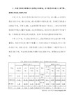
SONY MD编年史。
型号、发布时 间
特点
1 初创 2 初创
MZ-1 11/1992
MD的“开天之作”,砖头般的外形体积和重量,没有配 备线控。但是MZ-1的光纤、音频输入和使用方式确实和 今天完全相同。MZ-1的音质还不算很好,和CD相比要干 涩很多,不过它已经具备了10秒钟的防震功能。电池充 电七八个小时却只能播放一小时。MZ-2P作为第一部单 放MD随身听,播放时间1.25小时,拥有10秒防震,就是 MZ1的单放版。
MZ-R50 10/1997
有历史意义的产品,MZ-R50是一个传奇,至今人被很多 玩家追捧,它只有R30 70% 的体积,搭载16Mbit DRAM,提供40秒防震。可以同步录音,提供新型棒状液 晶线控,其搭配3.5MM标准耳机插孔。使用Lip-8型锂电 池,提供7小时回放时间,加上外接电池盒,一共是22 小时。
有历史意义的产品,世界上第一台支持MDLP的MD机,出 现了G-PROTECTION (G防震)功能(欧版,美版)。双 jog dial。新型棒状液晶线控。据了解Sony MZ-R900 是现今世界录放时间最长的 MiniDisc随身听,它采用 了索尼独创的 MDLP长时间录放技术,最新的大规模集 成电路(含16 m DRAM)提高了读取速度、减小了电量 消耗,在录放同时更可进行编辑操作。R900采用镁合金 外壳,光滑亮丽的漆面,手感非常不错。 LCD采用长条 形屏幕,金属按键设计得非常小巧,左右两边分别采用 “超级小旋风”旋钮式设计,左边是菜单及上下选择 键,右边是快键及后退键,主要按键全在机身正面,机 身背面只有同步录音键及HOLD键。采用“一键弹出”式 设计,弹出口在机身上方,换碟方便快捷。 R900的简化版,功能基本相同,只是附带无液晶的线控 。在亚洲还有一个PC版本,可以通过套件链接USB录音 (MD port 的由来)。81W x 28H x 75D mm, 116g R900的廉价版,没有线控。没有mic接口。83W x 28H x 76D mm, 113g R700的收音版,带收音调频线控。81W x 28H x 75D mm, 118g 内置立体声麦克风,扬声器,1。6X回放,40秒防震。 VOR功能(声音启动录音)。B系基本属于会议系列MD。 R900的单放版本,支持MDLP,播放LP4,可达100小时回 放时间。77.7 x 12.7 x 71.0mm, 58g E900的中价版,支持MDLP,播放时间同E900,只是体积 稍大,78.0 x 14.0 x 72.0mm, 85g E900的廉价版,支持MDLP,播放时间稍短75小时in LP4,体积大,线控无背光。80.5 x 17.7 x 74.5mm, 只发售与国外(日本以外)的低价MD单放,无MDLP,无 线控。只有20秒防震。83W x 27H x 77D mm, 83g。 走可爱路线的MD单放机,搭载MDLP。85.5 x 19.3 x 77.5mm, 72g MDLP搭载,分组功能,8档低音,带底座。74.5 x 80.5 x 17.9mm, 80g
MD简介介绍

06
MD的发展趋势和展望
MD的技术发展方向
01
智能化
MD技术将不断向智能化方向发展,通过引入人工智能、机器学习等技
术,提高MD的自动化和智能化水平,提高诊断准确性和效率。
02 03
精细化
随着医学技术的不断发展,MD技术将不断向精细化方向发展,通过高 分辨率、高灵敏度的检测设备,实现对微小病变的早期发现和准确诊断 。
04
便于版本控制:MD文档可以使用版本控制 工具进行管理,方便团队协作。
MD与其他相关技术的比较
与HTML比较
HTML是一种用于创建网页的标记语言,而MD是一种轻量级标记语言,可以转 换为HTML输出。相比之下,HTML语法复杂,需要一定的学习成本,而MD语 法简单易学,适合快速编写和编辑文档。
与Word、WPS等文档编辑软件比较
综合化
MD技术将不断向综合化方向发展,通过整合多种检测手段和信息,实 现多维度、多层次的综合性诊断,提高诊断准确性和全面性。
MD的应用前景和趋势
远程诊断
随着互联网技术的发展,MD技术将不断向远程诊断方向发展,通过远程会诊、远程诊疗 等方式,实现跨地区、跨医院的专业医疗服务。
个性化治疗
基于大数据和基因组学的研究,MD技术将不断向个性化治疗方向发展,根据患者的个体 差异,制定个性化的治疗方案,提高治疗效果和患者满意度。
MD的建模技术
原子模型
01
将材料的基本单元视为原子,通过原子间的相互作用来描述材
料的性质。
分子模型
02
将材料的基本单元视为分子,通过分子间的相互作用来描述材
料的性质。
连续介质模型
03
将材料视为连续介质,通过宏观物理量来描述材料的性质。
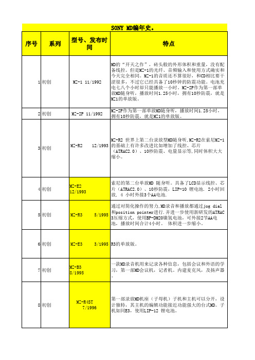
CN系列高性能计数器
测量状态 BA 键
BA 键
批次设定值修改状态
MD 键
▲
MD
七、比例系数功能
例:脉冲数P是旋转编码器旋转一周的脉冲数,L是测量的长度,系数值等于长度L/旋转编码器旋转一周的脉冲个数,它代表一个 脉冲所对应的实际长度.
计数器和旋转编码器控制长度
滚轮
刀具
旋转编码器
π×滚轮的直径( D ) 系数值 = ------------------------
一、型号说明
CN□□-R C□□
*24V供电电源可订做
通讯功能:0:无通讯 8:RS485通讯 显示位数:6:6位显示 报警输出:B:一路 C:二路 控制输出:R:继电器输出 S:固态输出 电源:空白:100-240VAC/DC F:24VDC供电 外形尺寸(mm):4:48H×48W×101L 7:72H×72W×100L
频率为:10~55Hz X,Y,Z各个方向1小时
振幅为:0.5mm
频率为:10~55Hz X,Y,Z各个方向10分钟
300/S 2 (约: 30G) X,Y,Z各个方向3次
100/S2 (约: 10G) X,Y,Z各个方向3次
10,000,000次以上 100,000次以上 (NO:250VAC 3A负载 NC:250VAC 2A负载)
四、面板名称
PS1: 下排显示OUT1设定值 PS2: 下排显示OUT2设定值 BA.S:上排显示批次计数值
下排显示批次设定值 复位键
CN7 SERIES COUNTER
OUT1,OUT2:OUT1或OUT2输出指示 BA.O:批次输出指示(CN4无此指示灯) LOCK:按键锁定指示
批次设定键
功能键 参数修改键
能操作U盘UD区的工具使用超详细教程

能操作U盘UD区的工具使用超详细教程[一]准备相关软件如下:1.Fbinst tool 1.6022.MsgDiyer2.0.33.百草霜fbinst_0PE合盘春节加强版:115网盘1、打开FbinstTool1.601V3版(以下出现的FbinstTool均为此版本!)2、使用FbinstTool格式化(注意备份数据,选择正确的磁盘,注意部分型号U盘不支持20480以上列表,比如我的朗科U228不支持大列表!)格式化参数的说明,如下图:3、格式化完成,空白的启动盘做好了,主分区+扩展分区我们统称“ud”,这个时候需要添加文件了。
添加合盘用的文件有两种方法,一种是把文件导入或拖入ud,另外一种是导入别人制作好的fba包。
4、◈◈【第一种情况:把文件拖入ud全新制作合盘】① 文件准备② 拖文件到ud③ 拖入文件后的结构④ 修改fbinst菜单⑤ 修改grldr内置菜单,改为合盘用的菜单◈◈◈〖方法二〗【Fbinsttool格式化后导入FBA包】1、首先用fbinsttool格式化U盘,按〖方法一〗中的方法做到下图的步骤。
2、点“数据管理”中的“从文件恢复数据”,选择FBA进行文件恢复3、导入成功后的文件结构◈◈◈〖方法三〗【Fbinsttool直接利用做好的FBA来格式化U盘】 [注:我个人不推荐这种方法] 1、用FBA作为模板来格式化U盘,准备好需要的文件2、选择准备好的FBA包,有必要的话可以修改格式化参数,这个根据实际情况。
3、用FBA模板格式化成功后的文件结构◈◈◈【制作好的fbinst启动盘,想打包成FBA,自己备份用或者给别人用的操作方法】1、制作好启动盘,进行一次“执行碎片整理”,然后点“备份数据到文件”,选择好目录,填好文件名字点保存即可。
◈◈【制作完成后的启动界面】1、启动到fbinst菜单2、启动到合盘菜单3、从fbinst菜单中按F2或者从合盘菜单中选择启动0PE后进入到0PE菜单.能操作U盘UD区的工具使用超详细教程[二]◈第二篇【Fbinst&0PE + 其他PE(我心如水)合盘制作过程】1、准备好制作好的Fbinst启动盘:这里拿Fbinst&0PE启动盘把合盘用的PE的ISO包,这里选用“我心如水 SERVER 2003 PE v14.66 维护版”!注:我心如水的这个版本的PE貌似不适合做fbinst合盘,我就拿这个特殊的PE来举例吧。
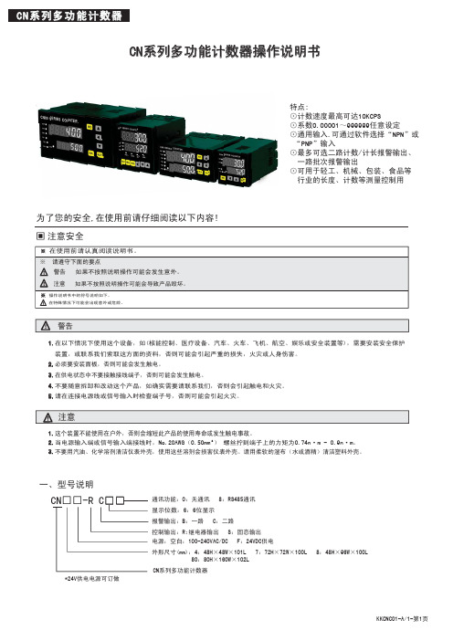
Control Techniques EF 安装指南:UD70 MD29 第二处理器选项说明书
EFInstallation GuideUD70MD29Second Processor Optionsfor Unidrive and Mentor IIPart Number:0460-0098Issue Number:2Safety InformationThe option card and its associated drive are intended as components for professional incorporation into complete equipment or systems.If installed incorrectly the drive may present a safety hazard.The drive uses high voltages and currents,carries a high level of stored electrical energy,and is used to control mechanical equipment that can cause injury.Close attention is required to the electrical installation and the system design to avoid hazards either in normal operation or in the event of equipment malfunction.System design,installation,commissioning and maintenance must be carried out by personnel who have the necessary training and experience.They must read this safety information and this Installation Guide carefully.Careful consideration must be given to the functions of the drive and option card which might result in a hazard,either through their intended functions,e.g.auto-start,or through incorrect operation due to a fault or trip,e.g.stop/start,forward/reverse,maximum speed, loss of a communications link.In any application where a malfunction of the drive or option card could lead to damage, loss or injury,a risk analysis must be carried out,and where necessary,further measures taken to reduce the risk.To ensure mechanical safety,additional safety devices such as electro-mechanical interlocks may be required.The Drive must not be used in a safety-critical application without additional high-integrity protection against hazards arising from a malfunction.General InformationThe manufacturer accepts no liability for any consequences resulting from inappropriate, negligent or incorrect installation or adjustment of the optional operating parameters of the equipment or from mismatching the Drive with the motor.The contents of this User Guide are believed to be correct at the time of printing.In the interests of a commitment to a policy of continuous development and improvement,the manufacturer reserves the right to change the specification of the product or its performance,or the contents of the User Guide,without notice.All rights reserved.No part of this User Guide may be reproduced or transmitted in any form or by any means,electrical or mechanical including photocopying,recording or by any information storage or retrieval system,without permission in writing from the publisher.Copyright©21/1/02Control Techniques Drives LtdIssue Code:2Hardware:UD70All Issues,MD29Issue3and laterFirmware:N/AContents1Mechanical Installation11.1Unidrive and UD7011.2Mentor II and MD29/MD29AN32Electrical Installation52.1UD7052.2MD2952.3MD29AN62.4RS232Port Connections62.5RS485Port Connections62.6I/O Box Port Connections(MD29Only)82.7Digital I/O Connections83RS485Port Configuration93.1Node Address93.2Data Rate103.3RS485Port Communications Modes103.4Storing configuration parameters12 UD70/MD29Installation GuideIssue Number:1UD70/MD29Installation GuideIssue Number:21Mechanical InstallationBefore attempting to installoption modules or cards,ensure that the Unidrive or Mentor II is switched off.AC Drives should be left for 5minutes to ensure that the DC link capacitors have completely discharged.1.1Unidrive and UD70•Slide the UD70module under the display panel of the Unidrive,and push the module in until the connector locates with the plug inside the Unidrive.•Apply firm pressure,and the module will click securely into place.•To remove the UD70,pull firmly on the black tab,and the module will disengage from the connector.3UD70/MD29Installation GuideIssue Number:21.2Mentor II and MD29/MD29ANThe MD29is fitted onto the 40-way pin header (PL1)on the MDA2B circuit board.The supplied mounting pillars should be attached to the MDA2B on the Mentor II.•Tilt the MD29at an angle and locate the first few pins into the MD29header.•Tilt the board to horizontal to engage the rest of the pins.Press firmly downwards to firmly fix the MD29to the header and4mounting pillars.Take care when locating the board onto this connector-do not force it on. Excessive force may bend and break the pins of the header.When removing an MD29,unsnap the MD29from the pillars before gently working the MD29off the header.Do not tilt the MD29excessively to one side,as this maybend and break the end groups of pins on the header.2Electrical Installation2.1UD70The UD70provides a dedicated RS232programming port(Connector C)and ageneral purpose RS485communications port(Connector D)..Connectors A and B provide the connectors for high speed fieldbus communicationoptions,if fitted.Refer to the appropriate fieldbus option User Guide for full fieldbusconnection details.2.2MD29The MD29provides a dedicated RS232programming port(Connector SK2)and ageneral purpose RS485communications port(Connector PL1).In addition,theMD29also has a dedicated RS485port(Connector TB1)for use with the ControlTechniques I/O Box.5UD70/MD29Installation Guide Issue Number:2UD70/MD29Installation Guide 6Issue Number:22.3MD29ANThe MD29AN provides a dedicated RS232programming port (Connector SK2)and a general purpose RS485communications port (Connector PL1).In addition,the MD29also has a dedicated CTNet port (PL2).2.4RS232Port ConnectionsThe pin connections for the RS232port are given in the table below.The RS232port can be connected to a 9way serial port using a 9-way one-to-one ribbon cable lead.2.5RS485Port ConnectionsThe pin connections for the RS485port are given in the table below 0VSC is completely isolated from the main Unidrive and Mentor II 0V.Pin Function Description 2TxD Transmit line 3RxD Receive line 50V0VPin Function Description10VSC 0VSC Isolated 0V for serial communications link.2TxA /Tx Inverted transmit line 3RxA /Rx Inverted transmit line 6TxB Tx Transmit line 7RxBRxReceive line7UD70/MD29Installation GuideIssue Number:22.5.14Wire RS485NetworkThe diagram below shows the connections required for a 4wire RS485network,using a master controller with an RS485port.The UD70and MD29can be configured to act as master controllers,but this requires DPL programming to control the network.An RS232-to-RS485converter is required to allow a standard PC serial port to communicate with a 4wire RS485network.2.5.22Wire RS485NetworkThe diagram below shows the connections required for a 2wire RS485network,using a master controller with an RS485port.The UD70and MD29can be configured to act as master controllers,but this requires DPL programming to control the network.An RS232-to-RS485converter with “intelligent transceiver switching”(also known as “magic”RS485converters)is required to allow a standard PC serial port to communicate with a 2wire RS485network.An example of a “magic”converter is the MA485F converter from Amplicon.A “magic”converter is not required is the master contoller has an RTS control output.This output is enabled when the master is transmitting,and disabled when the master is not transmitting.Control Techniques software packages (UniSoft,MentorSoft and SystemWise)do NOT switch the RTS line.2.6I/O Box Port Connections(MD29Only)The I/O Box port is marked“PL2”and is only available on the MD29.The terminalconnections are shown in the table below.Operation of this port is automatic,andno configuration is necessary.Pin Function Description10V0V0V2TxB Tx Transmit line3/TxA/Tx Inverted Transmit line4RxB Rx Receive line5/RxA/Rx Inverted Receive lineTo use the I/O Box with UD70or MD29AN,connect it to the RS485port,andselect Mode10communications.2.7Digital I/O ConnectionsThe RS485connector has2TTL digital inputs and1TTL digital output.They areused in conjunction with the Timer/Counter unit.(For further details,refer to theUser guide for the UD70or MD29.)The0VSC is isolated from the Unidrive or Mentor II0V,and should not be usedas the reference0V for the TTL digital inputs and output.If a digital input is open-circuit or connected to+5V,this will be read by#86.01(input0)or#86.02(input1)as logic0.These parameters will change to logic1when the inputs are connected to0V Digital on pin9.The digital output will give+5V when#86.03is set to logic0,and0V when set tologic1.The digital output is rated to a maximum of15mA.The maximum length ofcable that should be connected to these terminals is0.5metres,so buffering will berequired for longer lengths of cable,and for interfacing to different logic levels.The Digital inputs and output must be connected to0V Digital(pin9),NOTOVSC(pin1).The inputs and output will not work properly if connected toOVSC,as pin1is isolated from the Drive.Noise generated along the screenof the serial communications cable may cause spurious operation,anddamage to the UD70or MD29may result.3RS485Port ConfigurationThe RS485port can be used to communicate with the Drive using Control Techniques'standard software communications packages such as UniSoft,MentorSoft,CTFile and Systemwise.(Refer to the Help file in Unisoft,MentorSoft,etc.for connection details.)The ANSI protocol is the standard protocol used by the Control Techniques'software packages,but Modbus RTU and ASCII modes are also supported as slave nodes only.The RS485port is configured by setting certain user parameters on the Unidrive or Mentor II.These control individual features about the port.Any changes take effect when the configuration parameters are stored and the UD70or MD29is reset.The following parameters used to configure the RS485port.3.1Node AddressUnidrive:#17.05Mentor II:#14.01Range:11to 99,excluding 00to 09,10,20,30,40,etc for ANSI.1to 99for Modbus RTU and Modbus ASCIIDefault:11Every node on an ANSI or Modbus network MUST be assigned a unique serial address.Changes to the node address will not take effect until the parameters have been stored,and the UD70or MD29has been reset.The serial address ensures that only the intended node responds to commands issued by the network master controller.Each node should be assigned a unique address BEFORE it is connected to the RS485network.Function Unidrive (UD70)Mentor II (MD29/MD29AN)Node Address #17.05#14.01Data Rate#17.07#14.03Serial Comms Mode #17.06#14.02Pointer 1#17.08#11.09Pointer 2#17.09#11.10Scaling Factor #17.10#11.11Global Trip Enable #17.14#14.07RS485Trip Enable#17.15#14.083.2Data RateUnidrive:#17.07Mentor II:#14.03Range:300to 38400bits per second Default:4800Every node on an ANSI or Modbus network must be configured to operate at the same data rate.Set the appropraite value as shown in the table below to configure the RS485port data rate.3.3RS485Port Communications ModesUnidrive:#17.06Mentor II:#14.02The serial communications mode selector determines the mode of operation of the RS485serial port,and the protocol supported.Only slave modes are described here.(Modes 6to 9,11and 12require DPL code to control the RS485.)3.3.1Standard CT ANSI ProtocolMode 1-4Wire ANSI Slave Mode (Default)Mode 5-2Wire ANSI Slave ModeThe UD70and MD29will communicate using the Control Techniques'standard ANSI protocol with a 4-wire or 2-wire connection.This mode allows the Unidrive or Mentor II to communicate with standard CT software packages,such as UniSoft,MentorSoft,SystemWise,etc.Menu 0parameters are not accessible through a UD70or MD29.Refer to the User's Guide for MD29or UD70for a detailed description of the ANSI protocol.3.3.2Modbus RTUMode 13-4Wire Modbus RTU Slave Mode Mode 15-2Wire Modbus RTU Slave ModeThe UD70and MD29will communicate using the Modicon Modbus RTU protocol with a 4-wire or 2-wire connection.The data frame used for Modbus RTU is 1start bit,8data bits,no parity,2stop bits.(Even parity with 1stop bit is NOT currently supported.)The following MOdbus RTU commands are supported:FC3PRESET SINGLE REGISTER FC6PRESET MULTIPLE REGISTERS FC16READ MULTIPLE REGISTERSThe maximum number of registers that can be transferred on a single message is limited to 20,and the range of allowed node addresses is limited from 1to 99.Data Rate (bits/sec)Unidrive Mentor II30030036006006120012001224002400244800480048960096009619200192001923840038400383.3.3Modbus ASCIIMode14-4Wire Modbus ASCII Slave ModeMode16-2Wire Modbus ASCII Slave ModeThe UD70and MD29will communicate using the Modicon Modbus ASCII protocolwith a4-wire or2-wire connection.The data frame used for Modbus RTU is1startbit,7data bits,no parity,2stop bits.The following Modbus ASCII commands are supported:FC3PRESET SINGLE REGISTERFC6PRESET MULTIPLE REGISTERSFC16READ MULTIPLE REGISTERSThe maximum number of registers that can be transferred on a single message islimited to20,and the range of allowed node addresses is limited from1to99. 3.3.4Master/SlaveMode2-Master ModeMode3-Slave ModeIn Mode2,the node acts as a master,and continuously broadcasts a sourceparameter,as defined by the Pointer parameter,from the RS485port at a fixeddata rate of9600bits/sec.The value of the source parameter is scaled to±16000.In Mode3,the node acts as a slave to receive the continuous data streamtransmitted by a Mode2master.The incoming data is multiplied by the scalingparameter,and written to the destination parameter,as defined by the Pointerparameter.If the serial communications link is broken,the slave node can be made to trip.Thisis done by setting the Global Trip Enable and RS485Trip Enable parameters.3.3.5CascadeMode4-Cascade ModeMode4provides allows UD70and/or MD29RS485ports to be“cascaded”.Thismode is similar to the Master/Slave mode,except that each node can be a slave toan“upstream”node,AND a master to a“downstream”node.3.3.6I/O Box Mode(UD70and MD29AN only)Mode10-I/O Box ModeUnlike the MD29,the UD70and MD29AN do not have a dedicated port for use withthe I/O Box.The general purpose RS485port can be configured to communicatedirectly with an I/O Box by configuring the RS485port to use Mode10communications.3.4Storing configuration parametersIn all cases,the configuration parameters must be stored,and the UD70or MD29reset before changes will take effect.3.4.1Unidrive•To store changes in menu17parameters,set#MM.00to1000and press the red RESET button.•To reset the UD70,set#MM.00to1070and press the red RESET button.3.4.2Mentor II•Ensure that the Mentor II is disabed•To store changes in menu11and14parameters,set#MM.00to1and press RESET.This will also reset the MD29.。
(转贴)常见MD型号及稀有MD音质取向介绍

(转贴)常见MD型号及稀有MD⾳质取向介绍本来不想开这讲的,由于⾳质是⼗分主观的东西,如果擅⾃评价,很容易遭到⼤家炮轰,不过对于新⼿来说知道什么样的声⾳适合⾃⼰,什么样的机器的声⾳合适⾃⼰还是⼗分渴望的,所以恕本⼈⽃胆,开设这样⼀个具有历史性争议的课程,本⼈尽痢 观的评价,不带感情⾊彩,⾸先声明,由于要最⼤限度的提⾼客观性,本⼈只阐述其⾳质取向,不会象⼤部分⾳质测评那样⾏⽂⽂笔流畅,⽤词精挑细选,修饰天花乱坠。
SO。
可能会⽐较机械化。
SO。
请⼤家谅解。
SO。
开始吧。
SO。
(SO你个头啊,叫你继续SO!<暴打>)第⼀编: SONY本⼈听过最早的MD是R50,再⽼的MD没听过,R50之后基本⼤部分MD都听过。
(有些型号没听过,不过猜都猜得出来,电路设计都⼀样嘛)根据SONY的⾳质表现和声⾳取向本⼈将SONY的MD从R50开始直到NE810划分成三部分:第⼀部分:声⾳醇厚型有R50,R5ST,R55。
此类MD声⾳分辨率⾼,⾼频上限听感柔和(上限不⾼)全频⼗分饱满----⾼频相对现在的MD圆润,中频⼗分饱满,低频厚实,听感相对现在MD“模拟”味道更浓些,不是那么冷冰冰。
即使搭配838声⾳也不会硬。
这些MD代表着SONY较⾼的⾳质⽔平,此类机器刚开始从ATRAC蜕变到ATRAC3。
SONY为了标榜ATRAC3格式的优秀⾳质,在设计这部分MD时对于其运放部分投⼊了很多,毕竟优秀的运放可以⼀定程度上弥补⾳源的缺陷,况且,ATRAC3格式的⾳源已经⼗分优秀。
此类机器我觉得搭配的⽿塞范围⽐较⼴,即使搭配838也能出好声这⾥我说⼀些我的看法:关于曾经有些坛友说“R5ST⾳质优于R50”,其实两者⾳质作为随⾝听来说是完全相同的,但R5ST有个DECK,DECK上⾳频输出由于功率⾜够⼤,⾳质更优秀些,但单独使⽤随⾝听⽐较的话两者⾳质完全相同第⼆部分:声⾳平衡型有R90,R70,R900,R909,N1等。
此类SONY的MD声⾳解吸度⼗分⾼(个⼈觉得⽐N10还⾼,N10那解吸度是“假⾼”,这类是真⾼),声⾳放得开,速度感⽐起R50这代MD也恰倒好处,⾼频⾼⽽不刺,低频不温不⽕,但⼗分准确,质感⼗分好。
万能启动的最后传说:UD三分区法部署教程!UD加UEFI!
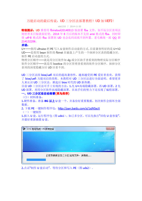
万能启动的最后传说:UD三分区法部署教程!UD加UEFI!zds1210 于2014-11-30特别提示:UD推荐用fbinstool20140513版部署fba文件,如不玩分区表项法则世界末日版就很好使;2014年8月后的版本不支持ansi格式的fba,同时即使utf-8格式的fba部署到UD也会乱码而找不到外置。
老毛桃统一派QQ群214132206。
术语:U+——指用ultraiso把PE写入U盘制作启动盘的方式,目前兼容性好的是U+V2 UD——是使用bean制作的fbinst在磁盘上产生的一个抹掉分区表的隐藏分区,制作PE启动盘的方式。
物理分区顺序——就是用分区软件如dg或分区助手查看到的物理实际分区顺序软件分区顺序——就是用bootice的分区管理查看到的软件分区顺序,抹掉分区表项的深度隐藏分区UD区看不到。
UD三分区法因bios/uefi双启的超高兼容性,越来越受到PE爱好者喜欢,获得了bios/uefi万能双启的美称。
本教程对UD三分区法进行全面说明,希望更多人来认识UD三分区法,掀起后bios时代的UD新热潮。
目前UD三分区法可手工实现的方法:1.先U+高端隐藏部署,再UD部署;2先UD部署,再用分区软件高端隐藏部署。
在高手们的努力下还实现了编程部署。
一、UD三分区法自动部署(菜鸟推荐)(〇)材料准备:1.硬件准备:准备8G以上U盘一个,并备份好重要数据,初次制作会损坏全部数据。
2. 下载PE一键制作程序包:/s/1sjNSscX(一)一键制作1.插入U盘,运行程序包(图uds1);如已多分区,可以先执行“回收U盘容量”,并最好重新插拨U盘。
2.点击“制作U盘启动”,等待分区和写入PE(图uds2)。
3.数据区格式为ntfs格式或exfat(ntfs支持无损调整分区好,但伤盘;exfat反之)(图uds3)。
并用佛大q emu启动器测试bios/uefi双启(下同,图uds4)。
MD随身听最全解读

末代MD传序(参考了墨索里尼传记写法)???在20世纪末至21世纪初的随身音频产品中,有哪一种随身听可以让看过它的人对于它的外观赞不绝口?有哪一种随身听引来了无数的口水,???——???从2006年,它是市场上一枝独秀。
总是有些人认为MD其实是一个失败品,正如一些“标准”的随身听发烧友所说的:“MD音质比不过CD,体积比不过MP3。
”但是,我可以告诉这些人,你们的观点是完全错误的。
不仅仅只是你们以长比短(请问您怎么不拿MD和CD比体积,或者和MP3比音质呢),更因为你们的说法彻底错误!“MD在随身听上的音质足以压倒一切CD随身听(不包括砖块),在体积方面虽然大于闪存MP3,但比硬盘MP3还是要小的多(直到今天也是)!”正文???很早就想写篇关于MD的帖子,但由于本人的惰性,一直拖到了2007年7月,后来由于在论坛发生意外,故直到今天才算是初步完工,在接下JVCMD并给???ST8802002低端SHARP篇???夏普MD无疑是MD中最好的。
无论是理论还是现实,夏普MD的音质都是最好的。
夏普是最早24BIT解码和数字放大技术的应用者。
早在97年夏普就已经是24BIT的解码了,直到1999年的爱华F80仍然还是采用20BIT 解码。
夏普的产品线,我认为要比SONY设计的更科学!ST/DS系列和MT/DR系列的区别绝对不仅仅只是体积和重量上的差别。
在EQ上,夏普分工明确,杜比耳机系统和某些EQ只有单放MD使用,可录MD再高端也只能传统的三段X-BASS(除DR7/77外,它们俱备了高音调节这个EQ)。
而杜比耳机系统又是夏普高端和低端单放MD的一个区别,就像DS5/30/33等无杜比耳机系统,而高端的DS8/70/77等全部配有杜比耳机系统。
当然这也???ST8802接近MD代的夏普MD皆是夸张不规则设计;同时机器正面开始采用高光亮漆。
??今年最引人注目的的还是首款NETMD_IM-MT880,因为NETMD此时被美誉“MP3杀手/终结者”。
MTT986-2006标准整理
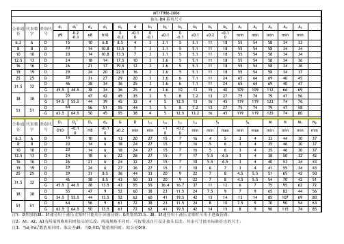
+0.1 +1 +0.2 ±0.2 min min min min max 0 0 0 15 6.3 6 D 10 6 13 20 27 15 7 16 4 5 20 8 8 D 14 6 18 24 27 15 7 16 5 6 20 10 10 D 14 6 18 24 27 15 7 16 5 6 24 12.5 13 D 18 6 22 28 27 15 7 17 5.5 6.5 26 16 16 D 21 6 24 32 27 15 7 18 5.5 6.5 29 19 19 D 24 6 27 36 27 15 7 18 6 7 39 25 25 D 31 8.5 36 44 33 20 9 22 7 8 46 D 38 8.5 43 50 33 20 9 22 7 8 31.5 32 G 45.5 46.5 38 13.5 43 55 55 36.4 16.7 37 11 12 55 D 47 9 52 60 38 23 11.5 24 7.5 9 38 38 G 54.5 55.5 44 13.5 52 62 60 41 19.5 42 13 14 64 D 56 9 61 72 38 23 11.5 24 8 10 51 51 G 63.5 64.5 50 13.5 61 72 62 41 19.5 42 14 15 注1:D类别的38、51通径用于液压支架时只能用于回液管路,G类别的31.5、38、51通径用于液压支架时可用于进液管路。 注3:当d1和d11数值相同时,取公差d9;当D1和D11数值相同时,取公差D10。
KJ 系列 O 形圈尺寸 公称通 代表数 类别代 O形圈 径 字 号 规格 6.3 8 10 12.5 16 19 25 31.5 38 51 6 8 10 13 16 19 25 32 31.5D 38 51 K K K K K K K K K K K 11X1.9 13X1.9 15X2.4 18X2.4 20X2.4 24X2.4 30X3.1 38X3.5 38X3.5 46X3.5 56X3.5 型号 QD-6 QD-8 QD-10 QD-13 QD-16 QD-19 QD-25 QD-32 QD-38 QD-51 QG-32 QG-38 QG-51
MD系列选型样本

5.1:电动操作器 DFD-0900…………71 5.2:电动操作器DFD-1300………………72 5.3:电动操作器DFD-010 ………………73 5.4:信号隔离器DC-DC…………………73 5 . 5: 球 形 铰… … … … … … … … … … … … 7 4 5.6:位置测量模块WB-…………………74
MB+RS400/F70ZY表示为角行程执行机构输出力矩4000Nm、三相电源、90°行程 时间为70秒、直联式安装方式、远控型控制方式。
TEL:022-23785511 23785522 FAX:022-23783388
30
天津-宝恒
MD系列角行程电动执行机构型号表
操作 力矩 Nm 100 250 600 1000 1600
电源线相距1英寸
M 三相
2
U
L1
3
V 三相固态继电器 L3
4
W
L5
CFR
20
BH700/002
21 三相380V 50HZ
22
电机热保护开关
力矩开关
LEF
LEO
FCO FCF
行程开 行程关
电位器
30 31 32 33
37 38
39
PM-5电路板
34
8 35
11
36
14
70
71 16
17
72
签相
73
18
1.50 2.70
4.50 14.0
2.50 2.70
13.0 14.0
3.40 4.40 7.20
20.0 27.0 37.0
9.10
52.0
SYSTIMAX HD和UD ULL纤线面板解决方案指南说明书
For high- and ultra high-density fiber environments with ultra low-loss capabilitiesSYSTIMAX ®HD and UD ULL fiber panels solution guide·Modular design makes moves, adds and changes (MACs) simple·Migrate from 10G through 25Gto 40/100G parallel without expanding the footprint·Modular design offers more flexibility and allows for incremental spending as needed·Available in LazrSPEED OM4 and OM5 Wideband and TeraSPEED to support current and future high-performance applications·Utilizes same footprint for duplex LCand MPO connections·Intuitive, flexible labeling solutions foreasy port identification·Large, translucent window providesclear view of the patching field·Supports imVision automatedinfrastructure management (AIM)solution·Split-tray design provides easyinstallation while minimizing networkdowntime·Tool-less install of rear trunkcables significantly reduces trunkdeployment time·Utilizes common modules across theUD/HD platformUD/HD solution comparisonPanel Adapter types Ports/RULC/MPOMax. fiber countHD 1U Duplex LC/MPO48/3296/768HD 2U Duplex LC/MPO96/64192/1536HD 4U Duplex LC/MPO192/128384/3072UD 2U Duplex LC/MPO144/96288/2304UD 4U Duplex LC/MPO288/192576/4608iPatch HD 1U Duplex LC/MPO48/3296/768iPatch HD 2U Duplex LC/MPO96/64192/1536iPatch UD 2U Duplex LC/MPO144/96288/2304 SCALABLE MANAGEABLE AGILESYSTIMAX® HD and UD ULL fiber panels solution guide 34 SYSTIMAX ®HD and UD ULL fiber panels solution guideMATERIAL IDPRODUCT CODEDESCRIPTION760209940HD-1U SYSTIMAX HD 1U sliding fiber panel, accepts (4) G2 ULL modules or MPO panels, providing up to 48 duplex LC ports or up to 32 MPO ports760209957HD-2U SYSTIMAX HD 2U sliding fiber panel, accepts (8) G2 ULL modules or MPO panels, providing up to 96 duplex LC ports or up to 64 MPO ports760209965HD-4U SYSTIMAX HD 4U sliding fiber panel, accepts (16) G2 ULL modules or MPO panels, providing up to 192 duplex LC ports or up to 128 MPO ports760210732HD-1U-FX SYSTIMAX HD 1U fixed fiber panel, accepts (4) G2 ULL modules or MPO panels, providing up to 48 duplex LC ports or up to 32 MPO ports760210740HD-2U-FX SYSTIMAX HD 2U fixed fiber panel, accepts (8) G2 ULL modules or MPO panels, providing up to 96 duplex LC ports or up to 64 MPO ports760210757HD-4U-FX SYSTIMAX HD 4U fixed fiber panel, accepts (16) G2 ULL modules or MPO panels, providing up to 192 duplex LC ports or up to 128 MPO ports760231506HD-1U-SP SYSTIMAX HD 1U Sliding fiber panel, accepts (4) 360G2 pigtail cassettes or 360DP panels, providing field term/splice capability up to 48 duplex LC ports 760231514HD-2U-SP SYSTIMAX HD 2U Sliding fiber panel, accepts (8) 360G2 pigtail cassettes or 360DP panels, providing field term/splice capability up to 96 duplex LC ports 760231522HD-4U-SPSYSTIMAX HD 4U Sliding fiber panel, accepts (12) 360G2 pigtail cassettes or 360DP panels, providing field term/splice capability up to 192 duplex LC portsSYSTIMAX HD panelsSTEP 1: SELECT PANELS AND ACCESSORIESSYSTIMAX ® HD and UD ULL fiber panels solution guide 5MATERIAL IDPRODUCT CODEDESCRIPTION760227306UD-2U SYSTIMAX UD 2U sliding fiber panel, accepts (12) G2 ULL modules or MPO panels, providing up to 144 duplex LC ports or up to 96 MPO ports760227314UD-4U SYSTIMAX UD 4U sliding fiber panel, accepts (24) G2 ULL modules or MPO panels, providing up to 288 duplex LC ports or up to 192 MPO ports760218461UD-2U-FX SYSTIMAX UD 2U fixed fiber panel, accepts (12) G2 ULL modules or MPO panels, providing up to 144 duplex LC ports or up to 96 MPO ports760218479UD-4U-FXSYSTIMAX UD 4U fixed fiber panel, accepts (24) G2 ULL modules or MPO panels, providing up to 288 duplex LC ports or up to 192 MPO portsMATERIAL IDPRODUCT CODEDESCRIPTION760207944HD-1U-REAR-EXT 1U Rear cable extension 760207951HD-1U-REAR-COVER 1U Rear blanking panel 760209627HD-2U-REAR-EXT -06-KIT 2U Rear cable extension760209981HD-4U-REAR-EXT -06-KIT 4U Rear cable extension—6 cable entries 760209999HD-4U-REAR-EXT -12-KIT 4U Rear cable extension—12 cable entries 760209619CABLE-MOUNT -KIT -12Cable attachment molding x 12760211078HD-1U-REAR-DOOR-COVER 1U Rear door760210286HD-2U-REAR-DOOR 2U Rear door 760210294HD-4U-REAR-DOOR 4U Rear door760032110MODG2-MGS G2 Modular MGS bezel (package of 4)760109462360G2-MOD-BLANK-4PKSYSTIMAX 360G2 Mod Panel Blank, 4 Panels760058677RMB-6-1/2 InstaPATCH Plus attachment bracket, rack mounted, six 1/2" fittings 760058685RMB-6-3/8 InstaPATCH Plus attachment bracket, rack mounted, six 3/8" fittings 760225920UD-2U-REAR-EXT -06-KIT 2UD Rear cable extension—6 cable entries 760236812UD-2U-REAR-EXT -12-KIT 2UD Rear cable extension—12 cable entries 760225938UD-4U-REAR-EXT -06-KIT 4UD Rear cable extension—6 cable entries 760225946UD-4U-REAR-EXT -12-KIT4UD Rear cable extension—12 cable entriesSYSTIMAX UD panelsSYSTIMAX HD/UD panel accessoriesMATERIAL ID PRODUCT CODE DESCRIPTION760217463HD-iP-1U-32-MPO-DP-SD HD iPatch enabled 1U 32-MPO distribution panel, sliding shelf 760217471HD-iP-2U-64-MPO-DP-SD HD iPatch enabled 2U 64-MPO distribution panel, sliding shelf760236401HD-iP-1U-96F-LC-DM08-ULL-LS-SD HD iPatch enabled 1U 96F-LC distribution MPO08 ULL module, LazrSPEED OM4, sliding shelf760236400HD-iP-1U-96F-LC-DM08-ULL-WB-SD HD iPatch enabled 1U 96F-LC distribution MPO08 ULL module, LazrSPEED OM5 Wideband, sliding shelf760236405HD-iP-1U-96F-LC-DM12-ULL-LS-SD HD iPatch enabled 1U 96F-LC distribution MPO12 ULL module, LazrSPEED OM4, sliding shelf760236404HD-iP-1U-96F-LC-DM12-ULL-WB-SD HD iPatch enabled 1U 96F-LC distribution MPO12 ULL module, LazrSPEED OM5 Wideband, sliding shelf760236409HD-iP-1U-96F-LC-DM24-ULL-LS-SD HD iPatch enabled 1U 96F-LC distribution MPO24 ULL module, LazrSPEED OM4, sliding shelf760236408HD-iP-1U-96F-LC-DM24-ULL-WB-SD HD iPatch enabled 1U 96F-LC distribution MPO24 ULL module, LazrSPEED OM5 Wideband, sliding shelf760236403HD-iP-2U-192F-LC-DM08-ULL-LS-SD HD iPatch enabled 2U 192F-LC distribution MPO08 ULL module, LazrSPEED OM4, sliding shelf760236402HD-iP-2U-192F-LC-DM08-ULL-WB-SD HD iPatch enabled 2U 192F-LC distribution MPO08 ULL module, LazrSPEED OM5 Wideband, sliding shelf760236407HD-iP-2U-192F-LC-DM12-ULL-LS-SD HD iPatch enabled 2U 192F-LC distribution MPO12 ULL module, LazrSPEED OM4, sliding shelf760236406HD-iP-2U-192F-LC-DM12-ULL-WB-SD HD iPatch enabled 2U 192F-LC distribution MPO12 ULL module, LazrSPEED OM5 Wideband, sliding shelf760236411HD-iP-2U-192F-LC-DM24-ULL-LS-SD HD iPatch enabled 2U 192F-LC distribution MPO24 ULL module, LazrSPEED OM4, sliding shelf760236410HD-iP-2U-192F-LC-DM24-ULL-WB-SD HD iPatch enabled 2U 192F-LC distribution MPO24 ULL module, LazrSPEED Wideband, sliding shelfSYSTIMAX iPatch panelsSTEP 1: CONTINUEDThe SYSTIMAX® iPatch® HD & UD fiber panels are a component of the imVision® automated infrastructure management (AIM) solution and provide intelligent connectivity to the data center.·Pa nels come pre-configured with Me thod B Enhanced ULL modulesSYSTIMAX iPatch HD Panels6 SYSTIMAX® HD and UD ULL fiber panels solution guideSYSTIMAX ® HD and UD ULL fiber panels solution guide 7·G2 ULL DM modules feature unpinned, rear MPO adapters to accept ULL MPO24, MPO12 or MPO8 preterminated trunk assemblies ·Shutters automatically actuated by connector insertion, allowing for one-handed operation ·Latch assist simplifies module removal for faster moves, adds and changes (MACs) ·Shutters designed to avoid ferrule contact during connector installation·Shutter door will illuminate when exposed to a visual fault locator (VFL) for easier circuit tracing ·Utilizing Method B Enhanced polarity maintenance, the ULL modules that all transmit and receive paths are correctly routed in parallel applications Note: AIM-compatible modules and preconfigured shelves available. iPatch modules do notuse internal shutters.STEP 2: SELECT MODULES AND ADAPTER PANELSMATERIAL IDPRODUCT CODEDESCRIPTION760236362UD-iP-2U-96-MPO-DP-SDUD iPatch enabled 2U 96-MPO distribution panel, sliding shelf760236367UD-iP-2U-288F-LC-DM08-ULL-LS-SD UD iPatch enabled 2U 288F-LC distribution MPO08 ULL module, LazrSPEED OM4, sliding shelf760236366UD-iP-2U-288F-LC-DM08-ULL-WB-SD UD iPatch enabled 2U 288F-LC distribution MPO08 ULL module, LazrSPEED OM5 Wideband, sliding shelf 760236369UD-iP-2U-288F-LC-DM12-ULL-LS-SD UD iPatch enabled 2U 288F-LC distribution MPO12 ULL module, LazrSPEED OM4, sliding shelf760236368UD-iP-2U-288F-LC-DM12-ULL-WB-SD UD iPatch enabled 2U 288F-LC distribution MPO12 ULL module, LazrSPEED OM5 Wideband, sliding shelf 760236371UD-iP-2U-288F-LC-DM24-ULL-LS-SD UD iPatch enabled 2U 288F-LC distribution MPO24 ULL module, LazrSPEED OM4, sliding shelf760236370UD-iP-2U-288F-LC-DM24-ULL-WB-SDUD iPatch enabled 2U 288F-LC distribution MPO24 ULL module, LazrSPEED OM5 Wideband, sliding shelfSYSTIMAX iPatch enabled UD panels8 SYSTIMAX ®HD and UD ULL fiber panels solution guideMATERIAL ID PRODUCT CODEDESCRIPTION760236109DM08-24LC-WB-ULL G2 ULL MPO-8 distribution module, 24LC to 3x8f MPOs unpinned, LazrSPEED OM5 Wideband internal shutter760236108DM08-24LC-LS-ULL G2 ULL MPO-8 distribution module, 24LC to 3x8f MPOs unpinned, LazrSPEED OM4 internal shutter760236111DM12-24LC-WB-ULL G2 ULL MPO-12 distribution module, 24LC to 2x12f MPOs unpinned, LazrSPEED OM5 Wideband internal shutter760236110DM12-24LC-LS-ULL G2 ULL MPO-12 distribution module, 24LC to 2x12f MPOs unpinned, LazrSPEED OM4 internal shutter760236113DM24-24LC-WB-ULL G2 ULL MPO-24 distribution module, 24LC to 1x24f MPO unpinned, LazrSPEED OM5 Wideband internal shutter760236112DM24-24LC-LS-ULL G2 ULL MPO-24 distribution module, 24LC to 1x24f MPO unpinned, LazrSPEED OM4 internal shutter760238082DM08-24LC-SM-ULL G2 ULL MPO-8 distribution module, 24LC to 3x8f MPOs unpinned, TeraSPEED SM internal shutter760238083DM12-24LC-SM-ULLG2 ULL MPO-12 distribution module, 24LC to 2x12f MPOs unpinned, TeraSPEED SM internal shutterG2 ULL internal shuttered modulesG2 ULL MPO-8 distribution module, 24LC to 3x8f MPOs unpinned, LazrSPEED OM5 Wideband dust caps iPatch readySYSTIMAX ® HD and UD ULL fiber panels solution guide 9MATERIAL ID PRODUCT CODEDESCRIPTION760216754360DPis-24LC-LS 360 LazrSPEED OM4 distribution panel, 24 LC, internal shutter, aqua760236041360DPis-24LC-WB 360 LazrSPEED OM5 Wideband distribution panel, 24 LC, internal shutter, lime green 760216762360DPis-24LC-SMSYSTIMAX 360 Distribution Panel 12 LC TeraSPEED BlueSYSTIMAX 360 internal shuttered adapter panelsMATERIAL ID PRODUCT CODEDESCRIPTION760107490 360DP-2MPO 360 2-MPO adapter panel 760107508 360DP-4MPO 360 4-MPO adapter panel 760107516 360DP-6MPO 360 6-MPO adapter panel 760107524360DP-8MPO360 8-MPO adapter panelSYSTIMAX 360 MPO distribution panelsNote: Internal shutters are not compatible with iPatch. For iPatch compatible modules, see below.MATERIAL ID PRODUCT CODEDESCRIPTION760115907360DP-24LC-LS 360 LazrSPEED OM4 distribution panel, 24 LC, iPatch ready, external shutter, aqua 760236042 360DP-24LC-WB 360 LazrSPEED OM5 Wideband distribution panel, 24 LC, iPatch ready, external shutter, lime green760216762360DPis-24LC-SMSYSTIMAX 360 Distribution Panel 12 LC TeraSPEED BlueSYSTIMAX 360 iPatch ready adapter panelsMATERIAL ID PRODUCT CODE DESCRIPTION760237217CM12-2x3-LS-ULL G2 ULL 2x3 LazrSPEED OM4 Conversion Module, (2) MPO-12 unpinned ports rear, (3) MPO-8 pinned front760237220CM12-4x6-LS-ULL G2 ULL 4x6 LazrSPEED OM4 Conversion Module, (4) MPO-12 unpinned ports rear, (6) MPO-8 pinned front760237218CM12-2x3-WB-ULL G2 ULL 2x3 LazrSPEED OM5 Wideband Conversion Module, (2) MPO-12 unpinned ports rear, (3) MPO-8 pinned front760237221CM12-4x6-WB-ULL G2 ULL 4x6 LazrSPEED OM5 Wideband Conversion Module, (4) MPO-12 unpinned ports rear, (6) MPO-8 pinned front760237216CM12-2X3-SM-ULL G2 ULL 2x3 TeraSPEED SM Conversion Module,(2) MPO-12 unpinned ports rear, (3) MPO-8 pinned front760237219CM12-4X6-SM-ULL G2 ULL 4x6 TeraSPEED SM Conversion Module,(4) MPO-12 unpinned ports rear, (6) MPO-8 pinned front760237222CM24-1x3-LS-ULL G2 ULL 1x3 LazrSPEED OM4 Conversion Module, (1) MPO-24 unpinned ports rear, (3) MPO-8 pinned front760237224CM24-2x6-LS-ULL G2 ULL 2x6 LazrSPEED OM4 Conversion Module, (2) MPO-24 unpinned ports rear, (6) MPO-8 pinned front760237223CM24-1x3-WB-ULL G2 ULL 1x3 LazrSPEED OM5 Wideband Conversion Module, (1) MPO-24 unpinned ports rear, (3) MPO-8 pinned front760237225CM24-2x6-WB-ULL G2 ULL 4x6 LazrSPEED OM5 Wideband Conversion Module, (2) MPO-24 unpinned ports rear, (6) MPO-8 pinned frontG2 ULL conversion modules·G2 ULL CM modules have unpinned rear MPO adapters for to accept ULL MPO24 or MPO12 preterminated trunk assemblies and pinned front MPO adapters to accept ULL MPO8 patch cords·New latch assist provides easier module removal for faster moves, adds and changes (MAC’s)·Utilizing Method B Enhanced polarity maintenance, the ULL modules guarantee that all transmit and receive paths are correctly routed in parallel applications10 SYSTIMAX® HD and UD ULL fiber panels solution guideSYSTIMAX ® HD and UD ULL fiber panels solution guide11·8-, 12- and 24-fiber MPO connector-based modules available in LazrSPEED 550 OM4 and LazrSPEED OM5 Wideband multimode fiber solutions·8- and 12-fiber MPO connector-based modules available in TeraSPEED singlemode fiber solutions ·Factory-terminated and tested trunk cables provide superior quality and performance for field connections ·Reliable transmit-to-receive connectivity using Method B Enhanced polarity maintenance maximizes administrative convenience ·Simplified reconfiguration for moves, adds and changes (MACs)·Easy upgrade path to parallel transmission and associated applications, and increased value of existing infrastructure ·SYSTIMAX ULL trunks are provisioned with pins to interface with G2 ULL modules (without pins)SYSTIMAX ULL MPO-12 trunk cablesSYSTIMAX ULL MPO-8 trunk cablesSYSTIMAX ULL preterminated trunk cablesSTEP 3: SELECT TRUNKS, ARRAYS, RUGGEDIZED FANOUTS, JUMPERSsinglemode standard is yellowsinglemode standard is yellow12 SYSTIMAX ® HD and UD ULL fiber panels solution guideSYSTIMAX ULL ruggedized fanout cablesSYSTIMAX ULL MPO-24 trunk cablesstandard is lime green·No female to female configurations·Male to female will be configured as trunk extensionsSYSTIMAX ® HD and UD ULL fiber panels solution guide 13·Duplex zipcord construction provides better mechanical performance with less risk of damage from crimping ·Rugged 1.6 mm cordage for durable and easily handled connections ·Outer jacket colored for easy identificationSYSTIMAX ULL fiber-optic LC patch cordsSYSTIMAX ULL fiber-optic MPO-8 patch cordssinglemode standard is yellowSYSTIMAX ULL fiber-optic MPO-12 patch cordsSYSTIMAX ULL fiber-optic MPO-24 patch cords14 SYSTIMAX ® HD and UD ULL fiber panels solution guide·TeraSPEED singlemode 8- and 12-fiber or multimode 8- 12- and 24-fiber MPO connectors ensure fast and simple connections ·All 8-fiber MPO arrays have QSFP wiring·Available in LazrSPEED 550 OM4 and LazrSPEED 550 OM5 Wideband multimode and TeraSPEED singlemode fibers·Factory-terminated and tested trunk cables provide superior quality and performance for field connections·MPO-LC array fanouts are constructed with 1.6-millimeter reinforced zipcord furcation tubing for outstanding durability and dependability·Array fanouts are available with multiple breakout lengths to simplify installationSYSTIMAX ULL LC array cordsavailable please contact CommScope*2P , 2X and 2C only available for multimode fiberSYSTIMAX ULL MPO array cords·8-, 12- and 24-fiber MPO connector-based modular design enables simple connections ·Array cords are constructed with LazrSPEED 550 OM4 and OM5 Wideband and TeraSPEEDsinglemode fibers ·Factory-terminated and tested for instant field connections giving guaranteed quality and performance ·MPO-MPO arrays are constructed with 3.0 mm PmP array cords·Arrays are available with multiple breakout lengths; minimum overall assembly length may vary based on breakout length selected (please see configuration table for specifics)*For use when there is more than one MPOconnector on one or both ends (ie: 1x2, 1x3, 2x3)PHYSICAL SPECIFICATIONSHDHD sliding fiber panel dimensions1U = 1.75 in H x 19 in W x 16.3 in D (44mm x 483mm x 414.5mm)2U = 3.50 in H x 19 in W x 16.3 in D (89mm x 483mm x 414.5mm)4U = 7.00 in H x 19 in W x 16.3 in D (178mm x 483mm x 414.5mm)Panel depth (behind mounting angles) 16.3 in (414.5mm)Panel projection (in front of mounting angles) 5.2 in (132mm)Tray travel = 5.00 in (127mm)HD sliding fiber panel weight (installation weight)1U = 12.4 lbs (5.62 kg)2U = 17.0 lbs (7.71 kg)4U = 24.8 lbs (11.25 kg)HD fixed fiber panel dimensions1U = 1.75 in H x 19 in W x 17.9 in D (44mm x 483mm x 455mm)2U = 3.50 in H x 19 in W x 18.2 in D (89mm x 483mm x 462mm)4U = 7.00 in H x 19 in W x 18.2 in D (178mm x 483mm x 462mm)HD fixed fiber panel weight (installation weight)1U = 9.0 lbs (4.08 kg)2U = 11.6 lbs (5.26 kg)4U = 16.0 lbs (7.26 kg)HD capacity1U = 4 G2 ULL DM modules, DM data modules or 360DP distribution panels 2U = 8 G2 ULL DM modules, DM data modules or 360DP distribution panels 4U = 16 G2 ULL DM modules, DM data modules or 360DP distribution panels UDUD sliding fiber panel dimensions2U = 3.50 in H x 19 in W x 16.3 in D (89mm x 483mm x 414.5mm)4U = 7.00 in H x 19 in W x 16.3 in D (178mm x 483mm x 414.5mm)UD sliding fiber panel weight (installation weight)2U = 21.2 lbs (9.62 kg)4U = 35.2 lbs (16.0 kg)UD fixed fiber panel dimensions2U = 3.50 in H x 19 in W x 18.2 in D (89mm x 483mm x 462mm)4U = 7.00 in H x 19 in W x 18.2 in D (178mm x 483mm x 462mm)UD fixed fiber panel weight (installation weight)2U = 11.6 lbs (5.26 kg)4U = 16.0 lbs (7.26 kg)UD capacity2U = 12 G2 ULL DM modules, DM data modules or 360DP distribution panels 4U = 24 G2 ULL DM modules, DM data modules or 360DP distribution panelsCable entryTrunk cable entry in the back; patch cords/fanouts entry in the front Termination types LC, MPOSide cable entries1U = 6 trunk cable entries (3 per side)2U = 12 trunk cable entries (6 per side)4U = 24 trunk cable entries (12 per side)Additional rear cable entries with optional cable extension kit1U = 6 trunk cable rear entries (HD-1U-REAR-EXT)2U = 6 trunk cable rear entries (HD-2U-REAR-EXT-06-KIT)4U = 6 trunk cable rear entries (HD-4U-REAR-EXT-06-KIT)4U = 12 trunk cable rear entries (HD-4U-REAR-EXT-12-KIT)SYSTIMAX® HD and UD ULL fiber panels solution guide 15Visit our website or contact your local CommScope representative for more information.© 2018 CommScope, Inc. All rights reserved.Unless otherwise noted, all trademarks identified by ® or ™ are registered trademarks, respectively, of CommScope, Inc. This document is for planning purposes only and is not intended to modify or supplement any specifications or warranties relating to CommScope products or services. CommScope is committed to the highest standards of business integrity and environmental sustainability with a number of CommScope’s facilities across the globe certified in accordance with international standards, including ISO 9001, TL 9000, and ISO 14001. Further information regarding CommScope’s commitment can be found at /About-Us/Corporate-Responsibility-and-Sustainability .BR-111679.4-EN (05/18)CommScope pushes the boundaries of communications technology with game-changing ideas and ground-breaking discoveries that spark profound human achievement. We collaborate with our customers and partners to design, create and build the world’s most advanced networks. It is our passion and commitment to identify the next opportunity and realize a better tomorrow. Discover more at 。
Denon UD-M3用户手册说明书

So, what goes into Optical In will go out of Optical 3 or 4, it seems. I have a similar capability, but with fewer Optical connections (i.e., 2, as opposed to your 4). Sorry, just guessing here. See less See more Thanks for the reply, I feel I'm half way there. With turning on Zone 2 (or 3) I've enabled the optical out, but now they are not sending a signal. I'm not sure how to configure the zones, I've never tried. How do I setup zone 2 to send optical our #3? There are no setups when I select different zones using the controller and I wasnt able to find anything in the main windows. Cant seem to get it working still. any help would be great. Zones 2 or 3 will only have audio signals thru ANALOG connections! Cheers. Regards, Chuck
Denon ud-m3 manual user manual
MD机功能解读

MD机功能解读●罗势全国祝驹国解凄部分囊中羞涩的发烧友经过一段时间的省吃俭用后,终于把新世纪的录音糟贵——MD随身听迎回家中.但头痛的事情亦随即产生,怎样才能把它物尽其用.当然简单的播放就算新手也很容易操作熟练,可是怎样使用各种录音与编辑功能就可能难倒报多新手了.大概读者会问,不是随机附带有说明书吗?为什么不会使用呢其宴蛐机不同于我们的其它家电产品那样随机附带中文或英文说明书.大部分都是只有日文说明,对于我们大部分不太熟悉电子技术的发烧友来说,船看懂英文电子术语已经报了不超了,更何况是日文呢,所以有说明往往等于投有说明,甚至更加会被诸多的说明弄得有点不明所以,这样一来就只有靠自己摸索了.不过这样也并非容易,在使用过程中蛐机的显示屏虽然会以英文缩写怍机器所处的状态,操作错谩等提示,而这些英文短语都是技术缩写(部分是特指),对于不熟悉MD技术的新手鞍难理解,这也令很多新手丈二金}II——摸不着头脑.为了让新手们可以得心应手地玩MD.特别是录音部\分,笔者以SONYMD机为样.所谓同步录音其实就是只要有信号才开始录音,当信号终止它也跟着终止录音,随心席虢之_黑静靠席l曩l蚋内窖舶准确峥睁——电予峭稿磊毫l誊曩,缺乏台法的发展空阿,若想有更大的影响,还需处理好与Micmeo~及电影出版青的关摹.注:Dh‟x与x鼍霄十不I噻的概念.Dr是由美国电子零售商CircuitCity前几年推出的一种DVD租售模式.用户可以以租借一盘DVD的价辂购买一部DIVXDVD碟片,在专用的DⅣx播放机上可以使用48小时《从第一次播放开始连续计时),从而省去用户归还碟片的麻烦.该模式从本质上说仍是即可.首先将DVD文件用theDeCss之类的Css(ContentscrambleSystem)解密软件解出不含音频的视频文件.此时的文件为MPEG2格式,将其用Divx编码软件压缩为A VI格式,同时将AC3音频转换成MP3音频,然后将音视频混台即可.目前已有很多网站提供DVD节目或片断的文件下载,当然,若非高速接人上网,下载速度也还是很慢的Db,x文件的播故目前也只能通过计算机进行,需要安装相应的软件,类似VCD的软解压,田像的质量在一定程度上取决于CPU的速度,基本要求是P2—300,64M内存,播放前需先运行I)ivx解码软件,然后用MediaPlayer或一般的DVD播放器(如PowerDVD)播放即可. Divx解码软件可通过相关甩站下载《如di性.ctw.∞),对于不同的操作系统,如Windows,NT,Linax等,分别有不同的版本.然而,对于电影出版商来说,oi任并不是一个好消息,它意昧着以DVD形式发行的电影节目将在网上迅速传播,节目的版权将得不到保证.电影出版业将可能面临由于MP3的问世而使唱片业遭受到相同的打击.Divx技术目前正处于迅速发展的阶段,虽然作为一种由黑客发明的非官方格式,缺乏统一的发展方向,但因其技术上的优越性,其发展势头丝毫不减,主要集中在提高压缩田像的质量,减少容量,以及寻求更好的压缩和播放工具上, 点滴的进展必然会引起质的飞跃.当然,性,这种功能真的为用户提供不少的方便.而实施也很简单,只要把”sYNCHRO REC”打开至ON的位置即可.若是要接续录音请按ENDSEARCH”即开始鳞续录音.用模拟录音方式优点在于那条过录线够平,容易买,但录音出来的效果却较数码录音差得多.如果你的音穗输出是数码音源也就是音穗有OPTICAL宇样的数字光纤输出孔而手头上也有条光奸线酃筑更好啦.此时你不要用模撤方式录膏了,马上改用数码录音吧.如果你正准备买条光纤线来录音那么以下的基本知识要注意:嗣为市塌上的敷字影音设备的…~OSLINK光圩接头一般分为两大类——角形接头与圆柱形接头.其实产品的缩号已有明确的标识,如SONY的POC一15A长1.5m,两边都是角形的接头:POC—ISB长1.5m.两边都是圆柱形的接头:POC一15AB长1.5m,一边是角形接头,而另一边剐是匮柱形的接头.角形接头用于.DECK”座{台式机), 组合音响上,而圆柱形的剐用在CD随身听和MD随身听上.必须按照你要接驳的机类选择光纤接线,千万不要买错.而数码录音的方式与模拟录音的方式一样茼单.首先用光纤线将音穗的0I,r【cALOUT”与MD机的”0PTICAL”连接好《见图3),然后再将MD片放人机体内,和模拟式录音一样,如果是第一次录音,请直接按REC,而采用同步录音则把SYNCHROREC打开至ON 就可以了.如是要接续录音请按.END SEARCH”即开始录音,十分方便.固为所以用外接的话筒(见图5)录音较适合上课,演讲,采访等要求需时较长且保真度高的场合使用.④■⑤MD虽然音质比不上DA T(数码录音机).但在录音编辑功能与方便性方面却好耨多,固为在录音编辑方面它匍.以显示歌名及专辑名称,可吐髓期磬群,合并,移动,曩辣歌曲,还可以知莲晕膏时间萼囊余时厦辱.丽豆最太謦存曲目数迭妇5曹,远参于CD的朔首l更神奇的是单声道及立体声可犀时存在恿张嘲)片中{下面我们豌一齐岳审l鹰其特殊功托...1.拜蕾卑台并若想把两首歌曲或片断完美地结合在一起,可以单纯用”合并”功能.但对于非同步录音或外接的话筒录音(鉴于在录音时会同时录入一些噪音或者是空白的录音片段)就要利用”先分割再合并”功能,达到删除噪音的目的.其原理是对你认为不需要的部分可以加上”曲头标志”(相当于将该部分的录音作为一段新的歌曲独立起来,这一曲头标志就是起到标识的作用).其实这部分属于分割,具体操作如下:在播放过程中,在想要的那一段即要分割的地方按”暂停”,然后再按”TMARK”键,此时屏幕上出现”MARKON”就会立即增加一个曲头标志.接着就可以任意地把曲头标志所标识的歌曲部分编辑了.例如,删除:首先令机器播放到想删除的那段录音部分,然后将机器处于删除状态下,按“MENU/ENTER”,在其菜单下选ERASE”,屏幕会显示”ERASEOK?”与sHENTER”,只要拄MENUIEN一咖确认会立即删除.前后乐曲头总成一首乐曲,这样就可以删除那些持续投有声音或者不理想部分,这属于合并.听上去很神奇其实操作起来并不复杂.学会了”分割合并”的复杂操作功能后单一的将两首或多首歌曲合并就变成茼单的事情.例如要将第1首的(Hl州2ooo)与第2首的(眼睛想旅行)合并.只要清除<眼睛想旅行)曲序号或者曲头标志就可以.具体操作:在正在撼放(aaPeY2ooo)的歌曲时.按暂停”键令其进人暂停状态然后轻按快速向前搜索”键,在找到曲头为(oo:oo)的标志时停止这时会在显示屏上瞬间显示”MARK”字样,然后再按”TMARK”键,当”MARK0盯”被显示在显示屏上时,表示此时(HAPPY2OOO)已与(服睛想旅行)连接起来了.2.改变乐曲囊序或M0lvE(警动)在一张MD特辑中.如果对某些曲日有所侧重.希望将它的曲日序号从后提前或戚后,所以Mb机中的改变乐曲顺序或者说是MOVE”(移动乐曲)功能就变为租重要了.具体操作:在按”播放”键同时,按”MENu/EN咖”键(在Mz.R91中此键称作MENU/ENTER)夸其成为单曲重复播放状态后,拨动搬动拨盘进人编辑状态.选择.MOVE”.继而按”EN‟I~R”确定,显示屏会提示从所在的曲日序号移动到”N序号(N是指准备要移刊的序号,如:3,4,5…),再用”快进/后退”或”微动按盘来选择指定移动位置的曲序号(中途中止时按”停止键).后再按.ENTER”键确认即可.3.加上曲名及光盘名称MD机可以使用日文(新机一般都有),罗马字(A—z的大小写),数字(0—9),符号(!”#★毒%&』)★+.一:<=> @一/:空格)等作为标记乐曲的曲名及光盘名称,最多能用200字,而在1张光盘中,最多可输人1700字之多,MD机的这种特殊录音功能给喜欢录音也祟尚个性化的玩家有更大的麓力.具体操作在编制盘符时首先按”停止”键而令其从其它状态下变为停止状态,按”MENU/ ENTER键进人.EDIT”文字编辑状态.上下推动微动控盘或按向前快进,向后快进,光标会左右移动,按大写罗马字/小写罗马字/记号/数字等顺序切换,选好后,用徽动投盘选择及确定文字即可.按”ENDSEARCH键则可以在输人位置上插人空白,可以加上1个字大小的文字,删除糖人位置上的文字,采用逐字删除.而编辑曲名则要在这首乐曲播放过程中,按”MENU/ENTER键夸其进人编辑文宇状态.然后用徽动控盘选择好文字,在确定后按下确定键.被造的文字会闲亮,在下一个文字的位置上光标闲烁让你继续输人.如果你认为已输人完毕就按住”MENU/ENTER,在半秒刊一秒时间后机器即可确认.注市场上出售的MD软件及未录音的光盘不能标上曲名或光盘名.MD与MD对拷后,如果要对每一首歌重新输人曲名造是很麻烦的事.适时采用”NameBank功臆就较方便了.它的席理是先将输人过韵曲名进行记录”,此时屏幕会出现ERASEOK?”的提示,后按ENTER进行确认即可.删除全部曲目:首先按”停止”键而令其从其它状态下变为停止状态按“MENU/ENTER”键进人”EDIT”,在其菜单中再选择”ERASE”,此时屏幕会出现“ALLERASE?与”PUSHENTER字样, 此时其要按”ENTER”即时可全部删除.5.外接话筒最青.操作:将专用话筒接于MIC孔上,再将待录的MD礤片放人机体内,推上REC录音键,令其进人录音状态,后按MENU/ENTER”健在菜单中先选择“RECMODE1,进人录音模式.此时在菜单中有”MONOREC(单声道录音)与“STEREOREC”(立体声录音)供你选择,如果你选择了某一项即可开始录音.在录音过程中可以自行设置录音电平,只要推上”REC按键后.在录音状态下按MENU/ENTER”键,此时休发觉其菜单下多出了”RECVOLUME”f录音电平控制),接ENTER进行确认后进人另一菜单.在此菜单下有.AU‟I~REC(自动设置录音电平)与”MANUALREC”(手动设置录音电平).如果选择了手动录音电平则屏幕会显示录音电平董,此时只要通过授动投盘上拨下拨或面板上的快进,快退键即可达到加大,减步录音输人电平的目的.当然上述的录音电平设置方式也同样适合于”机对机录音时使甩.…,显示屏英语提示MD属于高性能机种,所以它正处于什么状态或者出错都会在显示屏上通过英语作提示,所以通过懈读这些提示”使我们可以更好地了解MD机,更好地使用它们.主要英语提示有:△,请稍等片刻,此时也不要使其受到擅击或拔下其电源插头.△BUSY系统忙碌,请稍等一会,一般会需要太约1分钟.△NAMEFULL曲名及光盘名称的文字输人限制数200字.一张专辑文字输人碾制数约为1700字,请在文字眼制的数目内输人.吾捌出现该提示.△HIDCIN电豫电压高.选种情况一般出现在没有使用指定的AC电源转接器或电池.请使用指定的AC电源转接器或电池.△H0重D主机的保持功瞻工作,此时接什露t韩覆反应.棒HOLD开关向箭头相反方向攘神捌可■豫,姥控器也一样.△LOWⅫ电池瞻量消耗完要更换新的电池或再充电△MEMOVER当显示宙上没有任何显示时,在有震动的地方开始录音, 请在投有震的地方重新录音.△NOCOPY幕剜的复制管理幕统据SCMS禁止复制),请使用模拟信号输人(L卫NEIH)插口进行录音.△NODISC主机里没有放人光盘.放人光盘即可.△NOSIGNAL数字输人信号被切断.请确认数字输人的连接(输人模拟信号时可以忽税).△P/BONLY在进行录音或编辑时却误放人播放专用光盘,更换成录音用光盘即可.△PR棚啪D光盘处于防止误消除状态,拨回防止误消除开关.△s0mY试图消除光盘上第一首乐曲的曲头标记或试图消除不同种类乐曲与乐曲的曲头标记,倒如试图消除用立体声录音的乐曲与用单声道录音乐曲的曲头标记N/A.△TEMPOⅦR主机温度过高,请将本机放置阴凉处片刻后再使用. △TRF【曲号已超过254删除曲号,只要使其在254以内即可.△TRPROTECT当你试图在已经作磁道保护(防止乐曲误删除)乐曲进行录青囊簦蔫耐兢套出囊此挺示,请体录音或磐■其它舔抽.▲。
能操作U盘UD区的工具使用超详细教程
能操作U盘UD区的工具使用超详细教程[一]准备相关软件如下:1.Fbinst tool 1.6022.MsgDiyer2.0.33.百草霜fbinst_0PE合盘春节加强版:115网盘1、打开FbinstTool1.601V3版(以下出现的FbinstTool均为此版本!)2、使用FbinstTool格式化(注意备份数据,选择正确的磁盘,注意部分型号U盘不支持20480以上列表,比如我的朗科U228不支持大列表!)格式化参数的说明,如下图:3、格式化完成,空白的启动盘做好了,主分区+扩展分区我们统称“ud”,这个时候需要添加文件了。
添加合盘用的文件有两种方法,一种是把文件导入或拖入ud,另外一种是导入别人制作好的fba包。
4、◈◈【第一种情况:把文件拖入ud全新制作合盘】① 文件准备② 拖文件到ud③ 拖入文件后的结构④ 修改fbinst菜单⑤ 修改grldr内置菜单,改为合盘用的菜单◈◈◈〖方法二〗【Fbinsttool格式化后导入FBA包】1、首先用fbinsttool格式化U盘,按〖方法一〗中的方法做到下图的步骤。
2、点“数据管理”中的“从文件恢复数据”,选择FBA进行文件恢复3、导入成功后的文件结构◈◈◈〖方法三〗【Fbinsttool直接利用做好的FBA来格式化U盘】 [注:我个人不推荐这种方法] 1、用FBA作为模板来格式化U盘,准备好需要的文件2、选择准备好的FBA包,有必要的话可以修改格式化参数,这个根据实际情况。
3、用FBA模板格式化成功后的文件结构◈◈◈【制作好的fbinst启动盘,想打包成FBA,自己备份用或者给别人用的操作方法】1、制作好启动盘,进行一次“执行碎片整理”,然后点“备份数据到文件”,选择好目录,填好文件名字点保存即可。
◈◈【制作完成后的启动界面】1、启动到fbinst菜单2、启动到合盘菜单3、从fbinst菜单中按F2或者从合盘菜单中选择启动0PE后进入到0PE菜单.能操作U盘UD区的工具使用超详细教程[二]◈第二篇【Fbinst&0PE + 其他PE(我心如水)合盘制作过程】1、准备好制作好的Fbinst启动盘:这里拿Fbinst&0PE启动盘把合盘用的PE的ISO包,这里选用“我心如水 SERVER 2003 PE v14.66 维护版”!注:我心如水的这个版本的PE貌似不适合做fbinst合盘,我就拿这个特殊的PE来举例吧。
MD工作原理

MD工作原理MD是MiniDisc的缩写,首次于1992年由SONY发表,是一种专为唱片出版业界设计的磁光碟储存媒体。
其音质可接近于CD。
1993年,SONY又发表电脑储存资料用的MD Data Drive(这到和电脑上用的MO差不多了)。
"MiniDisc"这个名称源自于它小巧玲珑的外观,MD可擦写磁光盘本身的直径只有64毫米,厚度为1.2毫米,它内置于72X68X5毫米的硬塑料保护套中,看起来就和一张电脑用的三寸盘差不多结构。
所以一张MD比一张三寸盘还要小,而普通的CD(直径120毫米)更没法和它比了。
MD可以储存74分钟(立体声)或148分钟(单声道)的音乐,如果是MD DATA DRIVE(Sony台式电脑专用)的话,则可存贮相当于140M容量的电脑数据。
一张MD可记录255段歌曲,字幕总容量为1700个字(可显示的文字有英文、日文、特殊符号),现在也出现了可以显示中文的产品。
据SONY宣称MD有一百万次重复写入的能力(100万次,太多了吧),这也就是说理论上一张MD你可以一直用下去,不管你如何的听、录,数据可以保留很长的时间,这是磁带不可能做到的。
而且MD光盘的耐久性高也是有目共睹的。
和磁带的相当糟糕的录音品质以及CD容易磨损的特点相比较,MD几乎没有任何物理缺陷。
基本上外界因素不太会对MD磁光盘造成影响。
从MD机器的功能来说,可分为可录型MD(有磁头和雷射头两个头),和单放型MD(只有雷射头)。
MD使用的技术以及它们的特点:一、磁光烧录在工作原理上说,MD和MO是一样的,它源自于磁光记录技术(Magneto Optical,MO),而磁光记录技术的理论基础就是在高温下磁介质会发生变换,并且在冷却之后一直保持这种变化(记录过程),再次加热可以将其恢复到原先的样子(擦除过程)。
首先激光头对MD磁光盘发出780钠米波长、功率为4.5瓦的激光束,把纪录点区域加热到180摄氏度(也就是"居里温度",是把某种物质磁化的一个特定温度区域,MD光盘的合金材料的"居里温度"是180摄氏度),同时纪录磁头用正极或者负极信号来纪录声音数据的到磁光盘的加热点上,随着磁光盘的不停转动,新的数据不断地被同样的方式写入,纪录完毕的加热点逐渐冷却下来并保持加热时被赋予的磁信号。
德玛D5M系列通讯说明V1.1
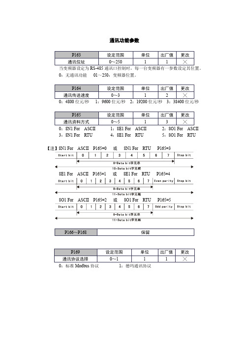
通讯功能参数当变频器设定为RS-485通讯口控制时,每一台变频器有一参数设定其位置。
0:无通讯功能01~250:变频器位置。
0:4800位元/秒1:9600位元/秒2:19200位元/秒3:38400位元/秒0:8N1 For ASCII 1:8E1 For ASCII 2:8O1 For ASCII3:8N1 For RTU 4:8E1 For RTU 5:8O1 For RTU 【注】8N1 For ASCII P165=0 或8N1 For RTU P165=38E1 For ASCII P165=1 或8E1 For RTU P165=48O1 For ASCII P165=2 或8O1 For RTU P165=50:标准Modbus协议1:德玛通讯协议德玛通讯协议格式(一)通讯协议两种方式RTU模式:每个8bit资料由两个4bit十六进制字元组成,如:64H (十六进制)。
ASCII模式:每个8bit资料由两个ASCII字元组成,如:64H(十六进制)以ASCII 码表示, 包含6(36H)和4(34H)。
1.起始位◆静音:表示50ms时间以上无串口中断◆STX:起始位“:”(3AH)2.数据格式◆ADDR:通讯位置(8bit)00:MODBUS广播方式01~250:变频器地址【注】ADDR=00时,无返回数据;ADDR≠00且与变频器地址一致时有响应。
◆CMD:命令码(8bit)01:读取功能码数据02:更改功能码03:写命令控制变频器状态04:读取当前变频器状态05:串口设定频率◆LEN:资料长度,指D(n-1)~D(0)的长度,长度设定:每8bit为单位长度。
◆DATA:资料内容,D(n-1)~D(0)。
3.校验位◆CRC:侦误值RTU模式,采用CRC(cyclical Redundancy Check)侦误值。
下列以C语言产生CRC值,此函数需要两个参数:unsigned char data←指信息缓冲区的指标unsigned char length←指信息缓冲区的位元组数目此函数将传回unsigned integer型态之CRC值。