Polarization enhancement in $vec{d}(vec{p}$,$^2$He)n reaction Nuclear teleportation
遥感数字图像的增强实验

(2)直方图匹配(Histogram Match)输入匹配文件(Input File):wasia1 mss.img匹配参考文件(Input File to Match ):wasia2_mss.img①ERDAS图标面板菜单条:Main 一Image Interpreter一Radiometric Enhancement —Histogram Match,打开Histogram Matching对话框。
②ERDAS图标面板工具条:点击Interpreter图标一Radiometric Enhancement 一Histogram Match,打开Histogram Matching对话框。
2)空间增强处理(Radiometric Enhancement)(1)卷积增强处理(Convolution)操作方法:(以文件Lanier.img为例)①ERDAS图标面板菜单条:Main一Image Interpreter一Spatial Enhancement一Convolution,打开Convolution对话框;②ERDAS图标面板工具条:点击Interpreter图标一Spatial Enhancement Convolution,打开Convolution对话框。
(2)自适应滤波(Adaptive Filter)操作方法:(以文件Lanier.img为例)①ERDAS图标面板菜单条:Main一Image Interpreter一Spatial Enhancement—Adaptive Filter,打开Wailis Adaptive Filter对话框。
②ERDAS图标面板工具条:点击Interpreter图标一Spatial Enhancement,Adaptive Filter,打开Wailis Adaptive Filter对话框。
参数设置:文件坐标类型(Coordinate Type ):Map;处理范围确定(Subset Definition):ULX/Y LRX/Y;输出数据类型(Output Data type ):Unsigned 8 bit;移动窗口大小(Moving Window Sire):3(表示3×3);输出文件选择(Optins):Bandwise(逐个波段进行滤波),或PC(仅对主成份变换后的第一主成份进行滤波);乘积倍数定义(Multiplier):2(用于调整对比度);输出数据统计时忽略零值:Ignore Zero in Stars;OK(关闭Wallis Adapter Filter对话框,执行自适应滤波)。
polarization
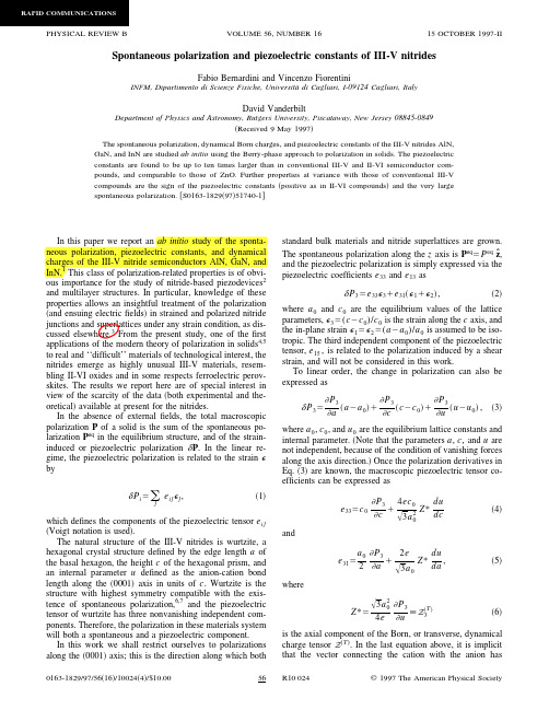
In this paper we report an ab initio study of the sponta-
neous polarization, piezoelectric constants, and dynamical
charges of the III-V nitride semiconductors AlN, GaN, and InN.1 This class of polarization-related properties is of obvious importance for the study of nitride-based piezodevices2
that the vector connecting the cation with the anion has
0163-1829/97/56͑16͒/10024͑4͒/$10.00
56 R10 024
© 1997 The American Physical Society
RAPID COMMUNICATIONS
In the absence of external fields, the total macroscopic
polarization P of a solid is the sum of the spontaneous polarization Peq in the equilibrium structure, and of the straininduced or piezoelectric polarization ␦P. In the linear regime, the piezoelectric polarization is related to the strain ⑀ by
Performing Fluorescence Polarization Assays on the

Multimode Detection Performing FluorescencePolarization Assays on theVICTOR NivoIntroductionFluorescence Polarization (FP) is a homogeneous assay formatthat is highly suitable for many applications from occasionalusage to high throughput screening, due to rather inexpensive reagents and its signal stability1. In FP assays, polarized light isused to determine the rotation capabilities of smallfluorescently labelled molecules. With this assay principle, onecan indirectly detect whether tracer molecules are bound to amuch larger molecule or are freely rotating in solution. Theseare rather complex interrelationships on the assay as well as on the device side compared to other homogeneous, plate reader compatible assays. Hence, for users, it is often difficult to set up an FP assay correctly.For this reason, we describe in this T echnical Note how to set up a Fluorescence Polarization assay on the VICTOR® Nivo™multimode plate reader and provide guidance for protocoloptimization. The VICTOR Nivo is a compact multimode plate reader that provides all detection modes which are routinelyused in drug discovery: Absorbance, Luminescence,Fluorescence Intensity, as well as options for Alpha, Time-Resolved Fluorescence and Fluorescence Polarization. Due toits intuitive control software and small footprint, the platereader fits easily in any lab.For research use only. Not for use in diagnostic procedures.As an example assay, the Predictor™ hERG Fluorescence Polarization Assay2 was used and its principle is shown in Figure 1, where the fluorescently labelled small moleculesof the Predictor™ hERG Tracer Red can either bind to the hERG channel protein in Predictor™ membrane fraction or can rotate freely.Blocking of the hERG potassium channel is known to be a potential off-target activity of drug candidates2,3, that can lead to life-threatening arrhythmias. For this reason, effects on the hERG channel are investigated early in the drug discovery process using various methodologies, one of them being the Fluorescence Polarization assay.VICTOR Nivo Multimode Plate Reader2Figure 2. Plate layout for the instrument setup run on the VICTOR Nivo.Instrument Setup Run for Predictor ™ hERG FP Assay The instrument setup run is a step used to optimize the FP measurement protocol specifically for the Predictor ™ hERGFluorescence Polarization Assay (Invitrogen, # PV5365) with regard to Z-height and G factor . For this experiment, a set of assay controls is needed: Buffer Blank, Assay Blank, Free tracer control, Negative control and Positive control. The controls were prepared according to the assay manual 5 and were transferred in triplicates to a black 384-well assay plate (PerkinElmer , ProxiPlate # 6008260 or OptiPlate # 6007270) at a volume of 20 ul/well (Figure 2).1. Selection of FiltersIn order to set up a FP measurement protocol on the VICTOR Nivo, three filters and a dichroic mirror are needed: a 530/30 nm excitation filter, two 580/20 nm emission filters and a 565 nm dichroic mirror. Alternatively, a 50/50 beam splitter can be used, but assay performance may be impaired. Dedicated polarization filters are not needed as the necessary polarizing components are already located inside the plate reader, if the instrument is equipped with FP technology.2. Z-focus Height OptimizationUsing a free tracer control well (reference polarization control), the Z-focus height optimization was demonstrated for a 384-well ProxiPlate and 384-well OptiPlate. A FP Z-focus scan protocol was set up (excitation at 530 nm, emission at 580 nm) with 20 scan points between 0 and 20 mm (Figure 3). The emission values (either S or P) were plotted in the VICTOR Nivo control software (Figure 4). The plate specific optimal Z-focus height was determined at the emissionintensity maximum. For future FP measurements, this Z-focus height was transferred to the FP endpoint protocol ofthe control software.Figure 1. Assay Principle. If polarized light excites Tracer Red bound to the hERG channel protein, the emission light remains polarized, because the tracer-channel-complex rotates slowly during fluorescent lifetime. In contrast, inhibiting compounds in the ion channel block Tracer Red from binding. In case Tracer Red is replaced in the ion channel by a compound, it rotates quickly during fluorescent lifetime due to its small size. This is leading to highly depolarized emission light, which is detected by the instrument not only in S, but also in P orientation.3Figure 3. Z-focus scan protocol for the plate specific optimization of the Z-focus height.3. G Factor CalculationThe G factor is a correction factor used to compensate for differences in parallel and perpendicular optical components of the measurement device. Calculating the G factor isrecommended, if the true polarization should be determined. Here, it was calculated using the free tracer control wells. In the Predictor ™ hERG FP Assay, this reference control has a known value of 50 mP 5. As a first step, the assay plate was measured once with the FP endpoint protocol including a G factor of 1. The S and P channel results were then used to calculate the G factor using Microsoft Excel according to the following formula:G =S*(1 – )mP (T racer )1000P*(1 + )mP (T racer )1000If the literature polarization value is not known for the used fluorophore, the relative change of polarization values (ΔmP) upon treatment can be plotted to create dose-responsecurves. For this, the G factor does not need to be adjusted and can be kept at 1. T o calculate ΔmP , all resulting mP values of the curve are normalized to an assay relevant sample showing low polarization values such as the free tracer control, positive control or even the lowest compound concentration in this example.As a rule of thumb, G is usually 0.8 < G < 1.2. The assayspecific calculated G factor was inserted in the FP endpoint protocol of the control software and the measurement of the assay plate repeated. The G factor was determined correctly, if the known mP value of the reference control (here 50 mP , see above) is obtained as a result.4Figure 5. Final VICTOR Nivo measurement protocol for the Predictor™ hERG FP assay shown here for 384-well ProxiPlates.Compound Testing in the Predictor ™ hERG FP AssayThe known hERG channel inhibitors Astemizole (Cayman chemical, #16967) and T erfenadine (Cayman chemical, #20305) were tested in 16-point dose response curves in a concentration range of 3.3 µM - 0.2 pM in the FP assay. T o allow data correction in case of unspecific compound effects, both compounds were also tested in the presence of a saturating concentration of the inhibitor E-4031 (30 µM). The plate layout is shown in Figure 6.First, the test compounds were dissolved in DMSO and a 3-fold dilution series was prepared. Afterwards, all samples were diluted 1:25 in assay buffer. Compounds were transferred to the assay plate at a volume of 5 µl/well. The tracer was diluted to 4 nM and 5 µl/well were transferred into the assay. Finally, 10 µl/well of the Predictor™ hERG Membrane were dispensed into a ProxiPlate (PerkinElmer, # 6008260). After 2 hours ofincubation at room temperature, the assay plate was placed in the VICTOR Nivo to run the FP protocol with the measurementsettings shown in Figure 5.Figure 4. Z-focus height optimization was demonstrated in PerkinElmer OptiPlate and ProxiPlate using a FP Z-focus scan protocol (excitation at 530 nm, emission at 580 nm) with 20 scan points between 0 and 20 mm. The emission intensity maximum (red intersecting lines) was determined directly in the VICTOR Nivo software.5Figure 6. Plate layout for Compound Profiling in the Predictor ™ hERG assay. The compounds Astemizole and T erfenadine were tested in 16-point dose response (3.3 µM - 0.2 pM, triplicates per concentration) in the presence and absence of the inhibitor E-4031.ResultsAfter optimizing the FP protocol on the VICTOR Nivo, it was used to measure the assay plate containing controls. As shown in Figure 7, the free tracer control results in 50 mP on average, showing that the G factor has been optimized correctly using the literature value 5. Nevertheless, the actual assay window is the span between the negative (tracer and membrane) and positive control (tracer, membrane and 30 µM E-4031) in these experiments ~100 mP . Comparable results were obtained in the OptiPlate and ProxiPlate at a volume of 20 µl (data not shown). In addition, it can be helpful to look not only at the mP results but also to calculate the total intensity with the formula 2*P+S. For example, background signal (assay blank and buffer blank) is often highly polarized, but the intensities are actually very low. T aking the total intensity into account during data analysis can therefore helpavoid misinterpretation of results.Figure 7. Resulting mP values (left) and total intensity (right) of assay controls in ProxiPlate after protocol optimization on the VICTOR Nivo. For each sample, the mean and standard deviation of three wells are shown.In a subsequent experiment, the known inhibitors T erfenadine and Astemizole were tested in dose response in the FP assay, results are shown in Figure 8. The FP signal was detected 2 hours after incubation. Assay statistics for the two independent experiments are summarized in T able 1. For the calculations,16 positive control wells and 16 negative control wells were used. The Z prime values of 0.73 and 0.87 indicate a robust assayperformance for both experiments.Figure 8. The compounds Astemizole and Terfenadine were tested in dose response experiments. The following IC 50 values were determined: IC 50 (Astemizole)= 0.97 nM and IC 50 (Terfenadine)= 2.8 nM. For comparison, the assay manual 5 reports an IC 50 value of 1.9 nM for Astemizole. For each data point, the mean and standard deviation of three wells are shown.For a complete listing of our global offices, visit /ContactUsCopyright ©2021, PerkinElmer, Inc. All rights reserved. PerkinElmer ® is a registered trademark of PerkinElmer, Inc. All other trademarks are the property of their respective owners.211120 (145315) PKIPerkinElmer, Inc. 940 Winter StreetWaltham, MA 02451 USA P: (800) 762-4000 or (+1) 203-925-4602ConclusionWe demonstrated the steps for FP protocol setup and optimization on the VICTOR Nivo and used the established measurement protocol for testing hERG inhibitors in dose response in two independent experiments. Using the protocol optimization steps described in this technical note, VICTOR Nivo’s simple and flexible software enables users to quickly optimize FP assays. Software features such as the graph view for Z-focus scans and the applied G factor make it easy for users to determine the correctmeasurement height and to directly export the polarization values. Also, the innovative filter wheel with its built-in polarizingcomponents makes it possible to use any Fluorescence Intensity filter combination for FP assays. No dedicated polarization filters are needed, only a second identical emission filter is required. In summary, this demonstrates that its ease of use of FP assays is a valuable addition to the VICTOR Nivo, along with its standard detection technologies.References1. Lea WA, Simeonov A. Fluorescence Polarization assays in small molecule screening. Expert Opin Drug Discov. 2011;6(1):17-32. doi:10.1517/17460441.2011.5373222. Piper DR, Duff SR, Eliason HC, et al. Development of the predictor hERG Fluorescence Polarization assay using a membrane protein enrichment approach. Assay Drug Dev T echnol. 2008;6(2):213-223. doi:10.1089/adt.2008.1373. Birgit Priest, Ian M. Bell & Maria Garcia (2008) Role of hERG potassium channel assays in drug development, Channels, 2:2, 87-93, DOI: 10.4161/chan.2.2.60044. Dierk Thomas, Christoph Karle & Johann Kiehn (2004) Modulation of hERG potassium channel function by drug action, Annals of Medicine, 36:sup1, 41-46, DOI: 10.1080/174313804100325805. Predictor hERG Assay Manual (Rev. date: 28 October 2009, https:///order/catalog/product/PV5365#/PV5365)。
matlab数字图像处理—图像增强汇总

图像增强图像增强的定义图像增强是指按特定的需要突出一幅图像中的某些信息,同时削弱或去除某些不需要的信息的处理方法,也是提高图像质量的过程[9]。
图像增强的目的是使图像的某些特性方面更加鲜明、突出,使处理后的图像更适合人眼视觉特性或机器分析,以便于实现对图像的更高级的处理和分析。
图像增强的过程往往也是一个矛盾的过程:图像增强希望既去除噪声又增强边缘。
但是,增强边缘的同时会同时增强噪声,而滤去噪声又会使边缘在一定程度上模糊,因此,在图像增强的时候,往往是将这两部分进行折中,找到一个好的代价函数达到需要的增强目的[10]。
传统的图像增强算法在确定转换函数时常是基于整个图像的统计量,如:ST 转换,直方图均衡,中值滤波,微分锐化,高通滤波等等。
这样对应于某些局部区域的细节在计算整幅图的变换时其影响因为其值较小而常常被忽略掉,从而局部区域的增强效果常常不够理想,噪声滤波和边缘增强这两者的矛盾较难得到解决。
常用的图像增强方法图像增强可分成两大类:空间域法和频率域法。
基于空间域的算法处理时直接对图像灰度级做运算;基于频率域的算法是在图像的某种变换域内对图像的变换系数值进行某种修正,是一种间接增强的算法。
基于空间域的算法分为点运算算法和邻域去噪算法。
点运算算法即灰度级校正、灰度变换和直方图修正等,目的或使图像成像均匀,或扩大图像动态范围,扩展对比度。
邻域增强算法分为图像平滑和锐化两种。
平滑一般用于消除图像噪声,但是也容易引起边缘的模糊。
常用算法有均值滤波、中值滤波。
锐化的目的在于突出物体的边缘轮廓,便于目标识别。
常用算法有梯度法、算子、高通滤波、掩模匹配法、统计差值法等。
基于频率域的算法把图像看成一种二维信号,对其进行基于二维傅里叶变换的信号增强。
采用低通滤波(即只让低频信号通过)法,可去掉图中的噪声;采用高通滤波法,则可增强边缘等高频信号,使模糊的图片变得清晰。
图像增强的方法是通过一定手段对原图像附加一些信息或变换数据,有选择地突出图像中感兴趣的特征或者抑制(掩盖)图像中某些不需要的特征,使图像与视觉响应特性相匹配。
《ERDAS IMAGE遥感图像处理方法》操作

《ERDAS IMAGE遥感图像处理方法》操作一空间增强(Spatial Enhancement)1卷积增强处理(Convolution)功能:用一个系数矩阵将整个图像按照象元分块进行平均处理,用于改变图像的空间频率特征。
to效果:地物的轮廓和线条勾勒变清晰了。
2非定向边缘增强(Non-directional Edge)功能:应用两个非常通用的滤波器(Sobel 滤波器和Prewitt 滤波器),首先通过两个正交卷积算子(Horizontal算子和Vertical算子)分别对遥感图像进行边缘检测,然后将两个正交结果进行平均化处理。
to效果:效果明显而且强烈分别出邻区不同的部分。
3.聚焦分析(Focal Analysis)功能:使用类似卷积滤波的方法,选择一定的窗口呼函数,对输入图像文件的数值进行多种变换,应用窗口范围内的象元数值计算窗口中心象元的值,达到图像增强的目的。
to效果:深色地方变模糊,浅色地物图象得到增强,但也变得不清晰。
4.纹理分析(Texture Analysis)功能:通过二次变异等分析使图象的纹理结构更加清晰。
to效果:纹理边缘部分十分清晰。
5.自适应滤波(Adaptive Filter)功能:应用自适应滤波器对图像的感兴趣区域进行对比度拉伸处理。
to效果:颜色变浅了。
6.分辨率融合(Resolution Merge)功能:对不同空间分辨率遥感图像的融合处理,使处理后的遥感图像即具有较好的空间分辨率,又具有多光谱特征,达到图象增强的目的。
+ =效果:处理后图象既有高分辨率又有多光谱特征(彩色)。
7.锐化增强处理(Crisp Enhancement)功能:对图像进行卷积滤波处理,使整景图像的亮度得到增强而不使其专题内容发生变化。
效果:区别不大,亮度得到些许增强。
二.辐射增强(Radiometric Enhancement)1.查找表拉伸(LUT Stretch)功能:通过修改图像查找表使输出图像值发生变化。
图像去雾增强算法的研究-文献综述

福州大学专业英语文献综述题目:图像去雾增强算法的研究姓名:学号:专业:一、引言由于近年来空气污染加重,我国雾霾天气越来越频繁地出现,例如:2012底到2013年初,几次连续七日以上的雾霾天气笼罩了大半个中国,给海陆空交通,人民生活及生命安全造成了巨大的影响。
因此,除降低空气污染之外,提高雾霾图像、视频的清晰度是亟待解决的重要问题。
图像去雾实质上就是图像增强的一种现实的应用。
一般情况下,在各类图像系统的传送和转换(如显示、复制、成像、扫描以及传输等)总会在某种程度上造成图像质量的下降。
例如摄像时,由于雾天的原因使图像模糊;再如传输过程中,噪声污染图像,使人观察起来不满意;或者是计算机从中提取的信息减少造成错误,因此,必须对降质图像进行改善处理,主要目的是使图像更适合于人的视觉特性或计算机识别系统。
从图像质量评价观点来看,图像增强技术主要目的是提高图像可辨识度。
通过设法有选择地突出便于人或机器分析的某些感兴趣的信息,抑制一些无用信息,以提高图像的使用价值,即图像增强处理只是增强了对某些信息的辨别能力[1].二、背景及意义近几年空气质量退化严重,雾霾等恶劣天气出现频繁,PM2。
5[2]值越来越引起人们的广泛关注。
在有雾天气下拍摄的图像,由于大气中混浊的媒介对光的吸收和散射影响严重,使“透过光"强度衰减,从而使得光学传感器接收到的光强发生了改变,直接导致图像对比度降低,动态范围缩小,模糊不清,清晰度不够,图像细节信息不明显,许多特征被覆盖或模糊,信息的可辨识度大大降低。
同时,色彩保真度下降,出现严重的颜色偏移和失真,达不到满意的视觉效果[3—6]。
上述视觉效果不佳的图像部分信息缺失,给判定目标带来了一定的困难,直接限制和影响了室外目标识别和跟踪、智能导航、公路视觉监视、卫星遥感监测、军事航空侦察等系统效用的发挥,给生产与生活等各方面都造成了极大的影响[7—9].以公路监控为例,由于大雾弥漫,道路的能见度大大降低,司机通过视觉获得的路况信息往往不准确,进一步影响对环境的判读,很容易发生交通事故,此时高速封闭或者公路限行,给人们的出行带来了极大的不便[10]。
一种改进的高斯频率域压缩感知稀疏反演方法(英文)
AbstractCompressive sensing and sparse inversion methods have gained a significant amount of attention in recent years due to their capability to accurately reconstruct signals from measurements with significantly less data than previously possible. In this paper, a modified Gaussian frequency domain compressive sensing and sparse inversion method is proposed, which leverages the proven strengths of the traditional method to enhance its accuracy and performance. Simulation results demonstrate that the proposed method can achieve a higher signal-to- noise ratio and a better reconstruction quality than its traditional counterpart, while also reducing the computational complexity of the inversion procedure.IntroductionCompressive sensing (CS) is an emerging field that has garnered significant interest in recent years because it leverages the sparsity of signals to reduce the number of measurements required to accurately reconstruct the signal. This has many advantages over traditional signal processing methods, including faster data acquisition times, reduced power consumption, and lower data storage requirements. CS has been successfully applied to a wide range of fields, including medical imaging, wireless communications, and surveillance.One of the most commonly used methods in compressive sensing is the Gaussian frequency domain compressive sensing and sparse inversion (GFD-CS) method. In this method, compressive measurements are acquired by multiplying the original signal with a randomly generated sensing matrix. The measurements are then transformed into the frequency domain using the Fourier transform, and the sparse signal is reconstructed using a sparsity promoting algorithm.In recent years, researchers have made numerous improvementsto the GFD-CS method, with the goal of improving its reconstruction accuracy, reducing its computational complexity, and enhancing its robustness to noise. In this paper, we propose a modified GFD-CS method that combines several techniques to achieve these objectives.Proposed MethodThe proposed method builds upon the well-established GFD-CS method, with several key modifications. The first modification is the use of a hierarchical sparsity-promoting algorithm, which promotes sparsity at both the signal level and the transform level. This is achieved by applying the hierarchical thresholding technique to the coefficients corresponding to the higher frequency components of the transformed signal.The second modification is the use of a novel error feedback mechanism, which reduces the impact of measurement noise on the reconstructed signal. Specifically, the proposed method utilizes an iterative algorithm that updates the measurement error based on the difference between the reconstructed signal and the measured signal. This feedback mechanism effectively increases the signal-to-noise ratio of the reconstructed signal, improving its accuracy and robustness to noise.The third modification is the use of a low-rank approximation method, which reduces the computational complexity of the inversion algorithm while maintaining reconstruction accuracy. This is achieved by decomposing the sensing matrix into a product of two lower dimensional matrices, which can be subsequently inverted using a more efficient algorithm.Simulation ResultsTo evaluate the effectiveness of the proposed method, we conducted simulations using synthetic data sets. Three different signal types were considered: a sinusoidal signal, a pulse signal, and an image signal. The results of the simulations were compared to those obtained using the traditional GFD-CS method.The simulation results demonstrate that the proposed method outperforms the traditional GFD-CS method in terms of signal-to-noise ratio and reconstruction quality. Specifically, the proposed method achieves a higher signal-to-noise ratio and lower mean squared error for all three types of signals considered. Furthermore, the proposed method achieves these results with a reduced computational complexity compared to the traditional method.ConclusionThe results of our simulations demonstrate the effectiveness of the proposed method in enhancing the accuracy and performance of the GFD-CS method. The combination of sparsity promotion, error feedback, and low-rank approximation techniques significantly improves the signal-to-noise ratio and reconstruction quality, while reducing thecomputational complexity of the inversion procedure. Our proposed method has potential applications in a wide range of fields, including medical imaging, wireless communications, and surveillance.。
联合训练生成对抗网络的半监督分类方法

光学 精密工程Optics and Precision Engineering第 29 卷 第 5 期2021年5月Vol. 29 No. 5May 2021文章编号 1004-924X( 2021)05-1127-09联合训练生成对抗网络的半监督分类方法徐哲,耿杰*,蒋雯,张卓,曾庆捷(西北工业大学电子信息学院,西安710072)摘要:深度神经网络需要大量数据进行监督训练学习,而实际应用中往往难以获取大量标签数据°半监督学习可以减小深度网络对标签数据的依赖,基于半监督学习的生成对抗网络可以提升分类效果,旦仍存在训练不稳定的问题°为进一步提高网络的分类精度并解决网络训练不稳定的问题,本文提出一种基于联合训练生成对抗网络的半监督分类方法,通 过两个判别器的联合训练来消除单个判别器的分布误差,同时选取无标签数据中置信度高的样本来扩充标签数据集,提高半监督分类精度并提升网络模型的泛化能力°在CIFAR -10和SVHN 数据集上的实验结果表明,本文方法在不同数量的标签数据下都获得更好的分类精度°当标签数量为2 000时,在CIFAR -10数据集上分类精度可达80.36% ;当标签 数量为10时,相比于现有的半监督方法,分类精度提升了约5%°在一定程度上解决了 GAN 网络在小样本条件下的过拟合问题°关键词:生成对抗网络;半监督学习;图像分类;深度学习中图分类号:TP391文献标识码:Adoi :10. 37188/OPE. 20212905.1127Co -training generative adversarial networks forsemi -supervised classification methodXU Zhe , GENG Jie * , JIANG Wen , ZHANG Zhuo , ZENG Qing -jie(School of E lectronics and Information , Northwestern Polytechnical University , Xian 710072, China )* Corresponding author , E -mail : gengjie@nwpu. edu. cnAbstract : Deep neural networks require a large amount of data for supervised learning ; however , it is dif ficult to obtain enough labeled data in practical applications. Semi -supervised learning can train deep neuralnetworks with limited samples. Semi -supervised generative adversarial networks can yield superior classifi cation performance ; however , they are unstable during training in classical networks. To further improve the classification accuracy and solve the problem of training instability for networks , we propose a semi -su pervised classification model called co -training generative adversarial networks ( CT -GAN ) for image clas sification. In the proposed model , co -training of two discriminators is applied to eliminate the distribution error of a single discriminator and unlabeled samples with higher confidence are selected to expand thetraining set , which can be utilized for semi -supervised classification and enhance the generalization of deep networks. Experimental results on the CIFAR -10 dataset and the SVHN dataset showed that the pro posed method achieved better classification accuracies with different numbers of labeled data. The classifi cation accuracy was 80. 36% with 2000 labeled data on the CIFAR -10 dataset , whereas it improved by收稿日期:2020-11-04;修订日期:2021-01-04.基金项目:装备预研领域基金资助项目(No. 61400010304);国家自然科学基金资助项目(No. 61901376)1128光学精密工程第29卷about5%compared with the existing semi-supervised method with10labeled data.To a certain extent, the problem of GAN overfitting under a few sample conditions is solved.Key words:generative adversarial networks;semi-supervised learning;image classification;deep learning1引言图像分类作为计算机视觉领域最基础的任务之一,主要通过提取原始图像的特征并根据特征学习进行分类[11o传统的特征提取方法主要是对图像的颜色、纹理、局部特征等图像表层特征进行处理实现的,例如尺度不变特征变换法[21,方向梯度法[31以及局部二值法[41等。
纹理物体缺陷的视觉检测算法研究--优秀毕业论文
摘 要
在竞争激烈的工业自动化生产过程中,机器视觉对产品质量的把关起着举足 轻重的作用,机器视觉在缺陷检测技术方面的应用也逐渐普遍起来。与常规的检 测技术相比,自动化的视觉检测系统更加经济、快捷、高效与 安全。纹理物体在 工业生产中广泛存在,像用于半导体装配和封装底板和发光二极管,现代 化电子 系统中的印制电路板,以及纺织行业中的布匹和织物等都可认为是含有纹理特征 的物体。本论文主要致力于纹理物体的缺陷检测技术研究,为纹理物体的自动化 检测提供高效而可靠的检测算法。 纹理是描述图像内容的重要特征,纹理分析也已经被成功的应用与纹理分割 和纹理分类当中。本研究提出了一种基于纹理分析技术和参考比较方式的缺陷检 测算法。这种算法能容忍物体变形引起的图像配准误差,对纹理的影响也具有鲁 棒性。本算法旨在为检测出的缺陷区域提供丰富而重要的物理意义,如缺陷区域 的大小、形状、亮度对比度及空间分布等。同时,在参考图像可行的情况下,本 算法可用于同质纹理物体和非同质纹理物体的检测,对非纹理物体 的检测也可取 得不错的效果。 在整个检测过程中,我们采用了可调控金字塔的纹理分析和重构技术。与传 统的小波纹理分析技术不同,我们在小波域中加入处理物体变形和纹理影响的容 忍度控制算法,来实现容忍物体变形和对纹理影响鲁棒的目的。最后可调控金字 塔的重构保证了缺陷区域物理意义恢复的准确性。实验阶段,我们检测了一系列 具有实际应用价值的图像。实验结果表明 本文提出的纹理物体缺陷检测算法具有 高效性和易于实现性。 关键字: 缺陷检测;纹理;物体变形;可调控金字塔;重构
Keywords: defect detection, texture, object distortion, steerable pyramid, reconstruction
II
Chemical modification of carbon nanotube for improvement of field emission property

Accelarated PublicationChemical modification of carbon nanotube for improvement of field emission propertySunwoo Lee a ,Tetsuji Oda a ,Paik-Kyun Shin b,*,Boong-Joo Lee caElectronic Engineering,The University of Tokyo,113-8656Hongo,Tokyo,JapanbSchool of Electrical Engineering,Inha University,#253Yonghyun-Dong,Nam-Gu,Incheon Metropolitan City 402-751,Republic of Korea cElectronic Engineering,Namseoul University,21Maeju-ri,Seounghwan-Eup,Cheonan City,Choongnam 330-707,Republic of Koreaa r t i c l e i n f o Article history:Received 17November 2008Received in revised form 31December 2008Accepted 17February 2009Available online 25February 2009Keywords:Chemical modification Carbon nanotube CNTField emission Tunnelinga b s t r a c tIn the present work,chemical modification of carbon nanotube was proposed for improvement of field emission property.Multi-wall carbon nanotubes (MWCNTs)were grown vertically on silicon substrate using catalytic chemical vapor deposition.Tips of grown MWCNTs were chemically modified using oxy-gen plasma,nitric acid,and hydrofluoric acid.Surface state and morphology of the chemically modified CNTs were T tips were opened and defects working as trap sites were generated on the CNT surface by the chemical modification process leading to improvement of field emission property.We suggest that two main factors determining the field enhancement factor are geometric factor and surface state of the CNT tips.Ó2009Elsevier B.V.All rights reserved.1.IntroductionCarbon nanotubes (CNTs)have attracted much attention be-cause of their unique electrical properties and their potential appli-cations [1,2].Large aspect ratios of CNTs with high chemical stability,thermal conductivity,and high mechanical strength are advantageous for applications to the field emitter [3].Since CNTs are grown directly on a substrate by CVD,the CNT emitter can be fabricated simply.Many researchers have devoted efforts to the artificial control of alignment,number density,and aspect ratio of CNTs [4–7].Although it is essential for FED application to eluci-date the correlation between the structural properties and field electron emission properties of CNTs,systematic experiments on the field emission property regarding the change of surface state of CNTs by chemical modification have not been carried out Ts having strong covalent bonds are very stable against to chemical attacks.Breaking these strong covalent bonds and chang-ing surface state would be expected to change the CNT’s physical property as well as chemical property [8,9].As field emission behavior takes place at the tip of the CNT,one could control the field emission property by changing the structure and surface state of the CNT tips.In this study,the correlation between the field emission prop-erty and structural property or surface state of CNTs was investi-gated as a function of the chemical modification.Although the field emission properties of CNTs were improved with increasing the aspect ratio of the CNT,the field enhancement factor obtained from the Fowler–Nordheim plot was found to be much larger than that obtained from the geometric factors.These results suggest that the field emission from CNTs is strongly influenced by the sur-face states induced by surface defects and attached functional groups,rather than by their geometric factors.2.ExperimentalIn our experiment,the nickel catalyst films were prepared by sputtering method on silicon substrate using low power and long time (at 10W for 1h)to minimize size and distribution of the nick-el catalyst particles.MWCNTs used in this work were grown in a thermal CVD system with C 2H 2source gas and Ar carrier gas with a flow rate of 30/100sccm at 700°C on the nickel catalyst.The CNTs were chemically modified by oxygen plasma,nitric acid (HNO 3),and hydrofluoric acid (HF).The modified samples were named as O 2–CNT,HNO 3–CNT,and HF–CNT,respectively.The oxygen plasma treatment was done with a gas flow rate of O 2:Ar =20:200sccm at 500°C for 5min.The HNO 3treatment was done in 20vol%HNO 3solution at room temperature for 1h,and the samples was subsequently rinsed in distilled water,and dried at room temperature for 1h.The HF treatment was done in 20vol%HF solution at room temperature for 1h,and the sample was rinsed and dried.0167-9317/$-see front matter Ó2009Elsevier B.V.All rights reserved.doi:10.1016/j.mee.2009.02.021*Corresponding author.Tel.:+82328607393;fax:+82328635822.E-mail address:shinsensor@inha.ac.kr (P.-K.Shin).Microelectronic Engineering 86(2009)2110–2113Contents lists available at ScienceDirectMicroelectronic Engineeringjournal homepage:www.else v i e r.c o m /l o c a t e /m eeThe field emission characteristics of the grown CNT film was measured by digital multimeter in a vacuum chamber with a base pressure of 1.5Â10À8Torr.A flat parallel diode type configuration was used in the setup as shown in Fig.1.Both electrodes were glass plated with a conductive indium tin oxide (ITO)coating,and the cathode contained the grown CNT film.The distance between the anode and the CNT film surface was 100l m as separated by spacers.The surface morphology and internal structure of the CNTs were characterized by scanning electron microscopy (SEM)and trans-mission electron microscopy (TEM).3.Results and discussionsSEM images and TEM images (right side of each image)of the as-grown CNTs and the chemically modified CNTs are shown in Ts grown in this work are bamboo type multi-wall carbon nanotubes,which are vertically aligned to the substrate.The length of chemically modified CNTs is slightly shorter than that of as-grown CNTs due to the chemical etching during the chemical mod-ification processes.In case of the HNO 3–CNT,length was drastically reduced,because CNTs were partly delaminated and remained CNTs were fallen down during the chemical modification process.Tip of as-grown CNT is typically closed,while those of chemi-cally modified CNTs are opened as shown in Fig.2(right side of each image).The most parts of CNT consist of stable hexagonal car-bon structure,while the tip of CNT has pentagonal structure to close the tube end [10].The pentagonal carbon structure is easily broken by the chemical attack relative to the hexagonal structure [11].Relatively weak bonds at the CNT tip might be broken and opened by the chemical modification.Since the bond breaking might be started from the outer shell of the MWCNT used in this work and propagated into the inner shell,the shape of CNT tips be-came sharp.Furthermore,the chemical modification process might result in changing the surface state by the bond breaking as well as the structural change.In order to confirm the above mentioned surface state change,X-ray photoelectron spectroscopy (XPS)using the monochrome Al Ka X-ray was carried out.Wide scan spectra for as-grown and chemically modified CNTs are shown in Fig.3.In all cases,carbon peak (C1s,284.5eV)and oxygen peak (O1s,530eV)are observed [12].The oxygen peak stronger than that of the as-grown CNT film for the O 2–CNT,the weak nitrogen peak for HNO 3–CNT,and fluo-rine peak for HF–CNT are observed.This result correspondstoFig.1.Schematic drawing of the setup for measurement of the field emissioncurrent.Fig.2.SEM (left)and TEM (right)images of as-grown and chemically modified CNTs.S.Lee et al./Microelectronic Engineering 86(2009)2110–21132111the previous TEM results that the chemical modification processes could change the surface states of the CNT tips.The chemical modification dependence on the field emission property was investigated.Fig.4a shows emission current density as a function of applied electric field for the as-grown CNTs and the chemically modified CNTs.It is found that the chemically modified CNTs exhibit a better field emission property than that for the as-grown CNTs.If we define the threshold electric field (E th )as the ap-plied electric field that produces an emission current of 1mA/cm 2,it can be clearly seen from Fig.4b that threshold electric field is chemical modification dependent.The Fowler–Nordheim (F–N)equation can be described as,J ¼1:56Â10À6ðb E Þ2/exp À6:83Â109/3=2b E!;where J (A/cm 2)is the emission current density,E (V/l m)is theapplied electric field,b is the field enhancement factor,and /(eV)is the work function of the emitter [13].The experimental value b can be estimated on the basis of the slope of the F–N plot as shown in Fig.4c.Although there is no distinguishable difference in geo-metric factors such as diameter and length of each CNTs,the field emission property for chemically modified CNTs is better than that for as-grown CNTs.We estimated the field enhancement factors for each CNTs using geometric factors from SEM images and the FN plot of the experimental field emission data.The field enhance-ment factor estimated from the FN plot (b $1000s)was two or-ders greater than that estimated from the geometric factors (b $10s).This result implies that the field enhancement factor estimated from the F–N plot includes another factor for the improvement of field emission.Another factor affecting field emis-sion more dominantly might be correlated with the surface state of the CNT tips.TEM results and XPS results strongly imply that defects working as trap sites might be on the CNT surfaces.As shown in Fig.4c,there are two different kinds of tunneling mechanism from the slope of J /E 2vs.1/E plots.The slope at low field regime is quite dif-ferent from that at high field regime.Trap sites play a dominant role in tunneling mechanism at lower field than FN tunneling re-gime,so called trap assisted tunneling (TAT)[14].Tunneling gov-erned by TAT mechanism at low field regime affect the threshold electric field,and is related to trap sites on CNT tips.The tunneling model is based on a two-step tunneling process via traps on CNT surface which incorporates energy loss by phonon emission [15].Fig.4d shows the basic two-step process of an electron tunneling from a region with higher Fermi energy (the cathode)to a region with lower Fermi energy (the anode).Electrons could be emitted at relatively low electric field with an aid of trap sites.Finally,we suggest that two main factors determining the field enhance-ment factor are geometric factor and surface state.Therefore gen-eration of trap sites on CNT surface is strongly required to improve the field emission property,as well as the geometricfactor.Fig.3.XPS wide scan spectra of the as-grown CNTs and the chemically modified CNTs.Since some parts of CNTs are delaminated during HNO 3chemical modification process as shown in Fig.2c,strong oxygen and silicon signals are detected from the naturally oxidized Si substrate.2112S.Lee et al./Microelectronic Engineering 86(2009)2110–21134.SummaryWe have found that CNT tips were opened and defects working as trap sites were generated on the CNT surface by the chemical modification process leading to improvement of field emission property.Trap sites play a dominant role in tunneling mechanism at lower field than FN tunneling regime.We found that another factor affecting the field emission might be correlated with the sur-face state of the CNT tips.Therefore generation of trap sites on CNT surface is strongly required to improve the field emission property,as well as the geometric factor.References[1]W.A.de Heer,A.Chatelain,D.Ugarte,Science 270(1995)1179.[2]B.I.Yakobson,R.E.Smalley,Am.Sci.85(1997)324.[3]T.W.Ebbesen,Carbon Nanotubes,CRC Press,Boca Raton,FL,1997.[4]M.Chhowalla,K.B.K.Teo,C.Ducati,N.L.Rupesinghe,G.A.J.Amaratunga,A.C.Ferrari,D.Roy,J.Robertson,ne,J.Appl.Phys.90(2001)5308.[5]Y.Y.Wei,G.Eres,V.I.Merkulov,D.H.Lowndes,Appl.Phys.Lett.78(2001)1394.[6]V.I.Merkulov,D.H.Lowndes,Y.Y.Wei,G.Eres,E.Voelkl,Appl.Phys.Lett.76(2000)3555.[7]M.Katayama,K.-Y.Lee,S.Honda,T.Hirao,K.Oura,Jpn.J.Appl.Phys.43(2004)L774.[8]W.K.Hong,H.C.Shin,S.H.Tsai,et al.,Jpn.J.Appl.Phys.39(2000)L925.[9]U.D.Weglikowska,J.M.Benoit,P.W.Chiu,et al.,Curr.Appl.Phys.(2002)2.[10]G.L.Martin,P.R.Schwoebel,Surf.Sci.601(2007)1521.[11]X.Y.Zhu,S.M.Lee,Y.H.Lee,T.Frauenheim,Phys.Rev.Lett.85(2000)2757.[12]F.Moulder,W.F.Stickle,P.E.Sobol,K.D.Bomben,Handbook of X-rayPhotoelectron Spectroscopy,Physical Electronics,Inc.,Minnesota,1995.[13]R.H.Fowler,L.W.Nordheim,Proc.R.Soc.Lond.Ser.(1928)A119.[14]M.Houssa,M.Tuominen,M.Naili,V.Afanas’ev,A.Stesmans,S.Haukka,M.M.Heyns,J.Appl.Phys.87(2000)8615.[15]F.Jiménez-Molinos,A.Palma,F.Gámiz,J.Banqueri,J.A.Lopez-Villanueva,J.Appl.Phys.90(2001)3396.Fig.4.(a)J –E curves of the as-grown CNTs and the chemically modified CNTs.(b)Threshold electric field as a function of chemical modification.(c)J /E 2–1/E curves of the as-grown CNTs and the chemically modified CNTs.(d)Field emission model considering trap sites on the surface of CNT tip.S.Lee et al./Microelectronic Engineering 86(2009)2110–21132113。
Lecture04-Enhancement1

Normalized histogram (probability):
pk nk / n
25
Digital Image Processing
© 2006 Haihong Hu
Image Enhancement – Point Processing Histogram (cont.)
An image with high contrast will show a great deal of gray level detail and have high dynamic range.
s L 1 r
8
Digital Image Processing
© 2006 Haihong Hu
Image Enhancement – Point Processing Log transforms
s clog(1 r) r 0
9
Digital Image Processing
Image Enhancement – Point Processing Gray-level slicing
19
Digital Image Processing
© 2006 Haihong Hu
Image Enhancement – Point Processing Gray-level slicing
Image Enhancement - 1 Spatial domain approaches
6
Digital Image Processing
© 2006 Haihong Hu
Image Enhanceme源自t - 1 Point processing
Simple intensity transforms
零部件光学影像精准定位的轻量化深度学习网络
第 31 卷第 17 期2023 年 9 月Vol.31 No.17Sept. 2023光学精密工程Optics and Precision Engineering零部件光学影像精准定位的轻量化深度学习网络牛小明1,曾理1*,杨飞2,何光辉1(1.重庆大学数学与统计学院,重庆 401331;2.长春长光辰谱科技有限公司,吉林长春 130000)摘要:光学影像精准定位是提高工业生产效率和质量的重要环节。
传统图像处理定位方法由于光照、噪声等环境因素的影响,在复杂场景下定位精度低、易受干扰;而经典深度学习网络虽然在自然场景目标检测、工业安检、抓取、缺陷检测等得到了广泛应用,但是其海量数据的训练需求、复杂系统的深度学习大模型、检测框的冗余及不精确等问题,导致它不能直接应用于工业零部件像素级精准定位。
针对以上问题,构建了一种零部件光学影像像素级精准定位的轻量化深度学习网络方法。
网络总体选用Encoder-Decoder架构,Encoder使用三级bottleneck级联,在降低特征提取参变量的同时充分提升了网络的非线性;Encoder与Decoder对应特征层实施融合拼接,促使Encoder在上采样卷积后可以获得更多的高分辨率信息,进而更完备地重建出原始图像细节信息;最后,利用加权的Hausdorff距离构建了Decoder输出层与定位坐标点的关系。
实验结果表明:轻量化深度学习定位网络模型参数为57.4 kB,定位精度小于等于5 pixel的识别率大于等于99.5%,基本满足工业零部件定位精度高、准确率高和抗干扰能力强等要求。
关键词:机器视觉;光学影像;深度学习;精准定位;轻量化中图分类号:TP391.4 文献标识码:A doi:10.37188/OPE.20233117.2611Lightweight deep learning network for accurate localization ofoptical image componentsNIU Xiaoming1,ZENG Li1*,YANG Fei2,HE Guanghui1(1.College of Mathematics and Statistics, Chongqing University, Chongqing 401331, China;2.Chang Chun Champion Optics Co., Ltd., Changchun 130000, China)* Corresponding author, E-mail: drlizeng@Abstract:Precise optical image localization is crucial for improving industrial production efficiency and quality. Traditional image processing and localization methods have low accuracy and are vulnerable to en⁃vironmental factors such as lighting and noise in complex scenes.Although classical deep learning net⁃works have been widely applied in natural-scene object detection,industrial inspection,grasping,defect detection, and other areas, directly applying pixel-level precise localization to industrial components is still challenging owing to the requirements of massive data training, complex deep learning models, and redun⁃dant and imprecise detection boxes. To address these issues, this paper proposes a lightweight deep learn⁃ing network approach for pixel-level accurate localization of component optical images. The overall design of the network adopts an Encoder–Decoder architecture. The Encoder incorporates a three-level bottle⁃文章编号1004-924X(2023)17-2611-15收稿日期:2023-06-05;修订日期:2023-06-19.基金项目:国家自然科学基金资助项目(No.62076043);国家重点研发计划资助项目(No.2020YFB2007001)第 31 卷光学精密工程neck cascade to reduce the parameter complexity of feature extraction while enhancing the network’s non⁃linearity. The Encoder and Decoder perform feature layer fusion and concatenation, enabling the Encoder to obtain more high-resolution information after upsampling convolution and to reconstruct the original im⁃age details more comprehensively. Finally, the weighted Hausdorff distance is utilized to establish the rela⁃tionship between the Decoder's output layer and the localization coordinates. Experimental results demon⁃strate that the lightweight deep learning localization network model has a parameter size of 57.4 kB, and the recognition rate for localization accuracy less than or equal to 5 pixels is greater than or equal to 99.5%. Thus, the proposed approach satisfies the requirements of high localization accuracy, high preci⁃sion, and strong anti-interference capabilities for industrial component localization.Key words: machine vision; optical image; deep learning; precise localization; lightweight1 引言机器视觉定位[1]是一种基于光学摄像头或其他传感器获取物体位置和姿态信息,并结合算法进行数据处理,最终实现对目标物体精确定位和跟踪的技术。
尼氏(Nissl)染色液说明书

尼氏(Nissl)染色液 产品编号产品名称包装sC0117 尼氏(Nissl)染色液 100ml产品简介:碧云天生产的尼氏(Nissl)染色液(Nissl Staining Solution)是神经生物学家广泛使用的一种Nissl 染色液,用于石蜡或冰冻切片神经元细胞浆中的尼氏小体(Nissl body)染色。
Nissl 染色是以德国的精神病学家和神经病理学家Franz Nissl 的名字命名的。
Nissl 染色液染色后呈蓝紫色,常用于显示脑或脊髓的基本神经结构。
Nissl 小体大而数量多,说明神经细胞合成蛋白质的功能较强;相反在神经细胞受到损伤时,Nissl 小体的数量会减少甚至消失。
本Nissl 染色液染色的有效成分是Cresyl violet 。
Cresyl violet 可以和RNA 或DNA 结合,可以染色粗面型内质网上的核糖体,也可以染色细胞核。
染色后使细胞体呈现斑驳的(mottled)蓝紫色染色。
一个包装的本染色液至少可以染色200个样品。
包装清单:产品编号产品名称 包装 C0117尼氏(Nissl)染色液 100ml — 说明书 1份保存条件:室温避光保存,至少一年有效。
注意事项:特别注意:Nissl 染色液的染色能力很强,并且染色后很难去除,请注意勿使染色液沾染皮肤和衣物等。
需自备4%多聚甲醛、70%乙醇和95%乙醇。
如果需要脱水、透明和封片处理,还需自备二甲苯,中性树胶或其它封片剂。
如果样品是石蜡切片,需自备90%乙醇,无水乙醇以及二甲苯。
样品数量较多时,可以使用碧云天生产的染色架和染色缸,便于操作。
第一次使用本试剂盒时建议先取1-2个样品做预实验。
本产品仅限于专业人员的科学研究用,不得用于临床诊断或治疗,不得用于食品或药品,不得存放于普通住宅内。
为了您的安全和健康,请穿实验服并戴一次性手套操作。
使用说明:1. 样品处理 a. 对于石蜡切片:二甲苯中脱蜡5-10分钟,共三次。
The Evolutionary Landscape of Alternative Splicing in Vertebrate Species

DOI: 10.1126/science.1230612, 1587 (2012);338 Science et al.Nuno L. Barbosa-Morais SpeciesThe Evolutionary Landscape of Alternative Splicing in VertebrateThis copy is for your personal, non-commercial use only.clicking here.colleagues, clients, or customers by , you can order high-quality copies for your If you wish to distribute this article to othershere.following the guidelines can be obtained by Permission to republish or repurpose articles or portions of articles): January 1, 2014 (this information is current as of The following resources related to this article are available online at/content/338/6114/1587.full.html version of this article at:including high-resolution figures, can be found in the online Updated information and services, /content/suppl/2012/12/19/338.6114.1587.DC1.htmlcan be found at:Supporting Online Material /content/338/6114/1587.full.html#related found at:can be related to this article A list of selected additional articles on the Science Web sites /content/338/6114/1587.full.html#ref-list-1, 35 of which can be accessed free:cites 75 articles This article /content/338/6114/1587.full.html#related-urls 16 articles hosted by HighWire Press; see:cited by This article has been/cgi/collection/evolution Evolutionsubject collections:This article appears in the following registered trademark of AAAS.is a Science 2012 by the American Association for the Advancement of Science; all rights reserved. The title Copyright American Association for the Advancement of Science, 1200 New York Avenue NW, Washington, DC 20005. (print ISSN 0036-8075; online ISSN 1095-9203) is published weekly, except the last week in December, by the Science o n J a n u a r y 1, 2014w w w .s c i e n c e m a g .o r g D o w n l o a d e d f r o moctatomic S,dimethyltrisulfide,and dimethyl-tetrasulfide,the latter two for about a combined 1mmole/g;the fragment contained in addition only naphthalene at2to8nmol/g,plus methyl-naphthalenes and biphenol in subnanomole amounts, but no alkanes or anthracene/phenanthrene.The SM meteorite demonstrates that the com-plexity of C-class asteroid surfaces is greater than previously assumed.Rapid terrestrial alteration probably erases many vestiges of the internal and external processes on the asteroid that remain to be explored in spacecraft sample-return missions.References and Notes1.M.Fries,J.Fries,Meteorit.Planet.Sci.45,1476(2010).2.P.Jenniskens,M.Zolensky,Meteorit.Bull.46,1(2012).3.Materials and methods are available as supplementarymaterials on Science Online.4.D.R.Christie,P.Campus,in Infrasound Monitoring forAtmospheric Studies,A.Le Pichon,E.Blanc,A.Hauchecorne,Eds.(Springer,Dordrecht,Netherlands,2010),pp.29−75.5.T.A.Ens,P.G.Brown,W.N.Edwards,E.A.Silber,J.Atmos.Sol.Terr.Phys.80,208(2012).6.E.A.Silber,A.Le Pichon,P.Brown,Geophys.Res.Lett.38,L12201(2011).7.M.H.Shaddad et al.,Meteorit.Planet.Sci.45,1557(2010).8.K.D.Smith et al.,Science305,1277(2004).9.H.Haack et al.,Meteorit.Planet.Sci.47,30(2012).10.H.Haack et al.,in Workshop on the First Solids in theSolar System,7to9November2011,Koloa,Kauai,Hawai’i(Lunar and Planetary Institute,Houston,TX,2011),abstr.9100.11.K.Nishiizumi,M.W.Caffee,Meteorit.Planet.Sci.44(suppl.),5358(2009).12.U.Ott,Rev.Mineral.Geochem.47,71(2002).13.V.S.Heber et al.,Geochim.Cosmochim.Acta73,7414(2009).14.I.Leya,nge,S.Neumann,R.Wieler,R.Michel,Meteorit.Planet.Sci.35,259(2000).15.M.Gounelle et al.,in The Solar System Beyond Neptune,M.A.Barucci,H.Boehnhardt,D.P.Cruikshank,A.Morbidelli, Eds.(Univ.of Arizona Press,Tucson,AZ,2008),pp.525–541.16.D.Nesvornýet al.,Astrophys.J.713,816(2010).17.K.J.Walsh,M.Delbo,W.F.Bottke,paper presented atthe44th American Astronomical Society/Division ofPlanetary Sciences Meeting,Reno,NV,14to19October,2012,abstr.305.04.18.A.Tsuchiyama et al.,Meteorit.Planet.Sci.44(suppl.),5189(2009).19.O.Popova et al.,Meteorit.Planet.Sci.46,1525(2011).20.D.S.Ebel,M.L.Rivers,Meteorit.Planet.Sci.42,1627(2007).21.R.J.Macke,D.T.Britt,G.J.Consolmagno,Meteorit.Planet.Sci.46,311(2011).22.D.T.Britt et al.,paper presented at the Meteoritical SocietyMeeting,Cairns,Australia,12to17August2012,abstr.5250.23.M.S.Spergel,R.C.Reedy,zareth,P.W.Levy,L.A.Slatest,J.Geophys.Res.91,483(1986).24.P.Rochette et al.,Meteorit.Planet.Sci.43,959(2008).25.J.Gattacceca,P.Rochette,Earth Planet.Sci.Lett.227,377(2004).26.A.Bischoff,E.R.D.Scott,K.Metzler,C.A.Goodrich,inMeteorites and the Early Solar System II,uretta,H.Y.McSween Jr.,Eds.(Univ.of Arizona Press,Tucson,AZ,2006),pp.679−712.27.R.J.Walker et al.,Geochim.Cosmochim.Acta66,4187(2002).28.Q-Z.Yin,K.Yamashita,A.Yamakawa,R.Tanaka,B.Jacobsen,D.S.Ebel,I.D.Hutcheon,and E.Nakamura,Lunar Planet.Sci.XL,abstr.2006(2009).29.J.M.Friedrich,M.-S.Wang,M.E.Lipschutz,Meteorit.Planet.Sci.37,677(2002).30.E.Tonui,M.E.Zolensky,M.E.Lipschutz,Proc.NIPRSymp.Antarct.Meteorites15,38(2002).31.M.Haq,F.A.Hasan,D.W.G.Sears,C.B.Moore,C.F.Lewis,Geochim.Cosmochim.Acta53,1435(1989).32.G.D.Cody et al.,Earth Planet.Sci.Lett.272,446(2008).33.E.D.Young,R.D.Ash,P.England,D.Rumble3rd,Science286,1331(1999).34.G.K.Benedix,L.A.Leshin,J.Farquhar,T.Jackson,M.H.Thiemens,Geochim.Cosmochim.Acta67,1577(2003).35.M.M.Grady,Astron.Geophys.50,4.21(2009).36.P.Schmitt-Kopplin et al.,Proc.Natl.Acad.Sci.U.S.A.107,2763(2010).37.G.W.Cooper,W.M.Onwo,J.R.Cronin,Geochim.Cosmochim.Acta56,4109(1992).38.A.A.Monroe,S.Pizzarello,Geochim.Cosmochim.Acta75,7585(2011).39.D.P.Glavin,M.P.Callahan,J.P.Dworkin,J.E.Elsila,Meteorit.Planet.Sci.45,1948(2010).40.J.R.Cronin,S.Pizzarello,Geochim.Cosmochim.Acta54,2859(1990).41.K.Lodders,Astrophys.J.591,1220(2003).42.E.Jarosewich,R.S.Clarke Jr.,J.N.Barrows,Eds.,Smithson.Contrib.Earth Sci.27,1(1986).43.P.G.Brown et al.,Science290,320(2000).44.R.N.Clayton,T.K.Mayeda,Geochim.Cosmochim.Acta63,2089(1999).45.R.N.Clayton,T.K.Mayeda,J.N.Goswami,E.J.Olsen,Geochim.Cosmochim.Acta55,2317(1991).46.R.N.Clayton,T.K.Mayeda,A.E.Rubin,J.Geophys.Res.89,C245(1984).47.G.J.MacPherson et al.,Geochim.Cosmochim.Acta73,5493(2009).48.E.D.Young,S.S.Russell,Science282,452(1998).Acknowledgments:The rapid recovery of SM was made possibleby the local communities of Lotus,Coloma,Pilot Hill,and GrassValley,due in part to the support of property owners,communityleaders,SETI Institute and University of Caifornia at Davis(UC Davis)student and volunteer searchers,and officials of the MarshallGold Discovery State Historic Park and the State of California.Wethank J.Howard,M.Carter,D.E.Macon,and L.Hofland of theNASA Ames Research Center;M.Hill of the American Museum ofNatural History;and G.Baxter,N.Botto,D.Rowland,O.Kreylos,L.Kellogg,and D.Summer of UC Davis for assistance with reportedmeasurements.The NASA Ames Research Center–coordinatedsearch efforts were supported by the NASA Lunar Science Institute.E.D.Y.,M.Z.,A.M.D.,D.S.E.,J.E.E.,K.N.,K.C.W.,M.H.T.,M.W.C.,Q.-Z.Y.,and S.B.S.acknowledge the NASA Cosmochemistry Programfor support of work reported here.In addition,the followingNASA programs are sincerely acknowledged:Near Earth ObjectObservation Program(P.J.),Origins of Solar Systems(S.A.S.),Planetary Major Equipment(Q.-Z.Y.),Sample Return LaboratoryInstruments and Data Analysis(M.W.C.),the NASA AstrobiologyInstitute(J.E.E.,J.P.D.,and D.P.G.),the SPring-8Grant Program(M.Z.),and Post Doctoral Programs(A.S.B.).P.R.H.acknowledgessupport from the Tawani Foundation.R.O.acknowledges KAKENHIgrants from the Japan Society for the Promotion of Science.Supplementary Materials/cgi/content/full/338/6114/1583/DC1Materials and MethodsSupplementary TextFigs.S1to S36Tables S1to S22References(49–105)9July2012;accepted12November201210.1126/science.1227163The Evolutionary Landscapeof Alternative Splicing in Vertebrate SpeciesNuno L.Barbosa-Morais,1,2Manuel Irimia,1*Qun Pan,1*Hui Y.Xiong,3*Serge Gueroussov,1,4* Leo J.Lee,3Valentina Slobodeniuc,1Claudia Kutter,5Stephen Watt,5RecepÇolak,1,6 TaeHyung Kim,1,7Christine M.Misquitta-Ali,1Michael D.Wilson,4,5,7Philip M.Kim,1,4,6 Duncan T.Odom,5,8Brendan J.Frey,1,3Benjamin J.Blencowe1,4†How species with similar repertoires of protein-coding genes differ so markedly at the phenotypic level is poorly understood.By comparing organ transcriptomes from vertebrate species spanning~350million years of evolution,we observed significant differences in alternative splicing complexity between vertebrate lineages,with the highest complexity in primates.Within6million years,the splicing profiles of physiologically equivalent organs diverged such that they are more strongly related to the identity of a species than they are to organ type.Most vertebrate species-specific splicing patterns are cis-directed. However,a subset of pronounced splicing changes are predicted to remodel protein interactions involving trans-acting regulators.These events likely further contributed to the diversification of splicing and other transcriptomic changes that underlie phenotypic differences among vertebrate species.V ertebrate species possess diverse phe-notypic characteristics,yet they sharesimilar repertoires of coding genes(1).Evolutionary changes in transcriptomes under-lie structural and regulatory differences asso-ciated with species-specific characteristics.Forexample,species-dependent mRNA and non-coding RNA(ncRNA)expression patterns havebeen linked to mutational changes in cis-andtrans-acting regulatory factors,as well as to phe-notypic differences(2–5).However,becauseorgan-dependent mRNA expression levels with-in individual species have been largely con-served during vertebrate evolution(6,7),it seemsunlikely that changes in gene expression(GE)1Banting and Best Department of Medical Research,DonnellyCentre,University of Toronto,Toronto,Ontario M5S3E1,Cana-da.2Instituto de Medicina Molecular,Faculdade de Medicina,Universidade de Lisboa,1649-028Lisboa,Portugal.3Departmentof Electrical and Computer Engineering,University of Toronto,Toronto,Ontario M5S3G4,Canada.4Department of Molec-ular Genetics,University of Toronto,Toronto,Ontario M5S1A8,Canada.5University of Cambridge,CRUK-Cambridge Institute,Robinson Way,Cambridge CB20RE,UK.6Department of Com-puter Science,University of Toronto,Toronto,Ontario M5S2E4,Canada.7Hospital for Sick Children,Toronto,OntarioM5G1X8,Canada.8Wellcome Trust Sanger Institute,GenomeCampus,Hinxton,Cambridge CB101SA,UK.*These authors contributed equally to this work.†To whom correspondence should be addressed.E-mail:b.blencowe@utoronto.ca SCIENCE VOL33821DECEMBER20121587RESEARCH ARTICLESaccount for the majority of phenotypic diver-sity among vertebrates.Through the variable use of cis-acting RNA elements in exons and flanking introns that are recognized by trans-acting factors,different pairs of splice sites in primary transcripts can be se-lected in a cell type–,condition-,or species-specific manner(8–15).Changes in alternativesplicing(AS)may therefore represent a majorsource of species-specific differences(16–25).Here,we describe a genome-wide investigationof AS differences among physiologically equiv-alent organs from vertebrate species spanning themajor tetrapod lineages.Evolution of alternative splicing complexity.High-throughput RNA sequencing(RNA-Seq)data were collected from whole brain,forebraincortex,cerebellum,heart,skeletal muscle,liver, Fig.1.Profiling of alternative splicing(AS)in vertebrates.(A)Relativeproportions of exons undergoing AS in each sample,as measured by de-tection of middle exon skipping in random exon triplets,where the threeexons are represented by orthologs in the analyzed species(y-axis unitsrelative to the sample with lowest AS frequency).See fig.S1,A and B,for amore detailed version;see table S5for details on samples,including rep-licates,and RNA-Seq data sets.(B)Percentage of common AS events be-tween human and other species.(C)Symmetrical heat map of Spearmancorrelations from PSI profiles.For each sample,PSI values for the1550orthologous exons in the11analyzed species were estimated.See fig.S4Afor a more detailed version.(D)Symmetrical heat map of Pearson correla-tions from gene expression(GE)profiles.For each sample,mRNA expres-sion[log cRPKM values(26)]of1809analyzed orthologous genes in the11analyzed species were estimated.Key as in(C).See fig.S4B for a moredetailed version.(E)Heat map of PSI values for41conserved cassette al-ternative exons.Rows,exons;columns,samples.Key as in(C).See fig.S11Bfor a more detailed version.Data are hierarchically clustered(complete meth-od,Euclidean distance)for heat maps in(C)to(E).21DECEMBER2012VOL338SCIENCE 1588RESEARCH ARTICLESkidney,and testis from human,chimpanzee,orang-utan,macaque,mouse,opossum,platypus,chick-en,lizard,and frog (26).For each species,we considered all internal exons as potential cassette AS events and created nonredundant databases of splice junction sequences formed by inclusion or skipping of each exon.RNA-Seq reads were mapped to the junction databases to determine “percent spliced-in ”(PSI)values,and also to rep-resentative transcript sequences from each gene to estimate GE levels,represented as “corrected reads per kilobase transcript model per million mapped reads ”(cRPKM)values (26).Orthology relation-ships between genes and exons were established to enable direct cross-species comparisons.The relative proportions of orthologous exons detected to undergo AS in each sample were de-termined.Equal numbers of reads were randomly sampled from each RNA-Seq data set to control for coverage differences (26).AS detection is ap-proximately twice as frequent in all analyzed pri-mate organs as in the equivalent organs from mouse and other species (Fig.1A and fig.S1).Moreover,there is an overall decline in AS fre-quency as the evolutionary distance from primates increases.These differences are significant (P <10−10,Mann-Whitney U tests),are robust to dif-ferent methods of AS frequency detection,and are independent of the variability in AS detection rates between individuals within the same spe-cies (Fig.1A and fig.S1).Genes with the highest AS complexity in human are significantly en-riched in cytoskeleton-associated functions (P <0.03)(table S1),which suggests that AS-directed diversification of the cytoskeleton may have been a driving force in the evolution of increased cel-lular complexity in vertebrate species.Rapid evolution of organ-specific alternative splicing.We next compared AS profiles across organs and species.Approximately half of al-ternatively spliced exons among species sepa-rated by ~6million years of evolution are different(Fig.1B and figs.S2A and S3A).When clus-tering organ AS profiles on the basis of how overall PSI values correlate in pairwise compar-isons,the samples segregate by individual spe-cies (Fig.1C and fig.S4A).This is in contrast to clustering samples on the basis of how their overall GE levels correlate,where the samples segregate according to tissue type (Fig.1D and fig.S4B)(6,7).Principal components analysis confirms that species type and tissue type are the primary sources of variability underlying the overall AS and GE patterns,respectively (figs.S5and S6).The species-dependent clustering of AS profiles is also observed when analyzing sub-sets of alternative exons associated with a wide range of splice site strengths,exon length,increased magnitudes of PSI change between tissues,increased read coverage,and also when using indepen-dently validated (16)PSI differences (figs.S7to S10).These results indicate that overall organ-specific AS patterns have evolved at a much more rapid rate than organ-specific GE patterns.However,when restricting the clustering anal-ysis to all (n =41)orthologous exons that are alternatively spliced in four species (human,mouse,chicken,and frog)representing the main tetrapod lineages,the samples segregate by tis-sue type,with similar results obtained with the larger data set of tissues and species (Fig.1E and fig.S11,A to H).The 41exons,on average,display a wider range of inclusion levels across the samples,indicating that they have a higher degree of regulatory potential (fig.S11I).Con-sistent with this observation,they are also asso-ciated with elevated exonic and flanking intronic sequence conservation,implying that they are under increased selection pressure to maintain binding sites for regulatory trans-acting factors (26).Therefore,although overall AS patterns of multiple organs distinguish vertebrate species,a small subset of exons that undergo AS in multi-ple species spanning ~350million years of evo-lution display conserved patterns of regulation that reflect organ type.We next investigated the relative rates at which AS and GE have evolved.From pairwise comparisons of PSI values in homologous tissues,we observe an overall increase of PSI diver-gence from human with evolutionary time (Fig.2A).In contrast to results from analyzing GE di-vergence (Fig.2,C and D)(6,7),AS levels in testis have not diverged more rapidly than in other tissues (Fig.2B),and AS events detected in neural tissues display the slowest rate of divergence (P <10−6,Mann-Whitney U tests).A significantly higher proportion (27%more on average)of neural AS events are conserved between vertebrate species than are AS events specific to other organs (P <0.002,Mann-Whitney U test;fig.S2B).These AS events are enriched in genes associated with synaptic transmission,axon guidance,neural de-velopment,and actin cytoskeleton reorganization (table S2),indicating that AS regulation of these processes is a highly conserved feature of ver-tebrate nervous system development.ABCD01002003004000.60.70.80.9Divergence from Human (Ma)P e a r s o n c o r r e l a t i o n o f G E w / H u m anC h i m p O r a n g u t a n M a c a q u eM o u s eO p o s s u m P l a t y p u sF r o gC h i c k e n L i z a r dcortex/brain cerebellum liver kidney heart muscle testisP u f f e r f i s hT r e e l e n g t hbrain01002003004000.00.20.40.6Divergence from Human (Ma)P e a r s o n c o r r e l a t i o n o f A S w / H u m ancortex/brain cerebellum liver kidney heart muscle testisC h i m p O r a n g u t a n M a c a q u eM o u s eO p o s s u m P l a t y p u sF r o gC h i c k e n L i z a r dP u f f e r f i s hbrainT r e e l e n g t hFig.2.Different rates of AS and GE divergence.(A )Pearson correlations between human and other species when comparing PSI values pairwise for conserved tissue-specific alternative exons in each tissue.For each pair of samples,correlation is analyzed for PSI values for all exons undergoing AS in both samples.(B )Comparisons of total tree lengths (bootstrapping,100replicates)of PSI trees for con-served tissue-specific alternative exons from six tissues in seven species (human,chimp,macaque,mouse,opossum,platypus,chicken).Statistically significant differences between the neural and each of the other tissues are indicated (Mann-Whitney U tests).Full PSI trees for each tissue are shown in fig.S3B.(C )Pearson correlations between human and other species when comparing GE pairwise (cRPKM,log scale;1809orthologous genes in the 11analyzed species)in each organ.(D )Comparisons of total tree lengths (bootstrapping,100replicates)of expression trees from analyzing six organs from seven species as in (B).Statistically significant differences between testis and each of the other tissues are indicated (Mann-Whitney U tests).Full expression trees for each tissue are shown in fig.S3C.SCIENCEVOL 33821DECEMBER 20121589RESEARCH ARTICLESEvolution of vertebrate splicing codes.To investigate mechanisms underlying the diver-gence in organ AS profiles,we used a splicing code derived from mouse data (27,28)to com-pare cis-regulatory elements that are predictive of tissue-dependent splicing patterns of five or-gans (brain,heart,skeletal muscle,liver,and kid-ney)from the four representative species analyzed above.The splicing code achieved high classi-fication rates when predicting organ-specific AS patterns from sequence alone.The average true positive rate [AUC,area under the receiver op-erating characteristic (ROC)curve]ranges from 68to 70%for heart exon skipping to 80to 88%for brain exon inclusion (Fig.3,A and B,and fig.S12).An exception was a subset of approximate-ly 200exon-skipping AS events in human brain,which were predicted less well (AUC =62%)(fig.S12)(26).A comparison of the most strongly predictive cis-elements accounting for each species ’organ-dependent splicing patterns revealed that these significantly overlap in most tissues (Fig.3C and fig.S12).Such cis-elements may represent features comprising an ancestral vertebrate splic-ing code (Fig.3D).However,the overlap between sets of splicing code features used in a given pair of species decreases with increased evolutionary distance (Fig.3C and fig.S12;see also below).Thus,organ-dependent AS patterns appear to be generally controlled by significantly overlapping cis-regulatory codes,although progressive diver-gence in these codes likely also contributes to AS differences.Species-specific alternative splicing is primar-ily cis-directed.The extent to which evolutionary change in cis-regulatory codes (versus trans-acting factors)accounts for species-dependent AS differences is not known.To address this,we used a mouse strain,Tc1,carrying the ma-jority of human chromosome 21(HsChr21)(29).We compared PSI values of exons from HsChr21transcripts expressed in multiple organs (brain,liver,heart,testis)from the Tc1strain,with PSI values of the identical exons in the correspond-ing human organs.We also compared PSI val-ues for the orthologous mouse exons between wild-type and Tc1mouse strains.For all com-parisons,we analyzed a comprehensive set of 13HsChr21and orthologous mouse exons that were detected,using RNA-Seq data,toFig.3.Inference and comparative analysis of vertebrate splicing codes.(A )ROC curves of splicing code predictions for brain-dependent exon inclusion in human,mouse,chicken,and frog.ROC curves for other tissues are shown in fig.S12.(B )AUC in percent for each of the ROC curves in (A).(C )Left:Heat map of splicing code features with significant prediction scores associated with brain-specific exon inclusion in each species (red for P <0.05,Mann-Whitney U test);statistically significant features in common with all significant mouse features associated with brain-specific exon inclusion are shown.Right:Pro-portions of features significantly associated with mouse brain-specific exon inclusion also significant for brain-specific exon inclusion in other species.Error bars:95%confidence intervals,Pearson ’s c 2proportion tests.Analyses of predictive features for other tissues are shown in fig.S12.(D )Region-specific distribution of code features significantly associated with tissue-specific exon inclusion or exclusion in all four species,as determined by their region-specific enrichment or by their predictive power as inferred by the splicing code.Splicing factors associated with code features are in square brackets.Significantly enriched features are indicated by hollow arrows;features both significantly enriched and predictive are indicated by bold arrows.Arrows are colored according to the organ with which the features are associated (refer to key).21DECEMBER 2012VOL 338SCIENCE1590RESEARCH ARTICLEShave undergone AS in at least one of the two species.All analyzed HsChr21exons that are alterna-tively spliced in human for which the orthologous exons in mouse are constitutively spliced are also alternatively spliced in the Tc1mouse;likewise,all HsChr21constitutively spliced exons for which the orthologous exons in mouse are alternatively spliced are also constitutively spliced in the Tc1mouse (P <0.02,both comparisons;one-sided Fisher ’s exact tests;Fig.4,A and B,and fig.S13A).For the orthologous exons that are alternatively spliced in human and mouse,we observe a sig-nificantly higher correlation between their inclu-sion levels in Tc1mouse and normal human organs relative to the correlation observed when comparing inclusion levels of all orthologous hu-man and mouse exons (r =0.89versus r =0.52,P <0.0008,one-sided Z-test;fig.S13B)(26).Collectively,the results indicate that changes among predominantly conserved cis-regulatory elements are sufficient to direct the majority of the species-specific AS patterns,at least in hu-man and mouse.However,because our results also indicate that vertebrate splicing codes di-verged with increasing evolutionary distance,and because specific subsets of AS events could not be reliably predicted using the splicing code,changes in trans-acting factors likely also con-tributed to evolutionary differences in AS.Species-classifying alternative splicing events in trans-acting regulatory factors.To investigate which splicing changes during evolution likely had the greatest functional impact,we identified AS events that best discriminate or “classify ”spe-cies (26).These AS events have relatively large and widely expressed PSI differences between species or lineages,and were validated at a high rate by reverse transcription polymerase chain reaction (RT-PCR)assays (r =0.90,n =180;fig.S14).Gene Ontology enrichment analysis re-veals that the corresponding genes are function-ally diverse,with “nucleic acid binding ”among the most frequently represented categories (Fig.5A,fig.S14,and tables S3and S4).Consistent with a major role for conserved cis-regulatory elements governing species-dependent AS pro-files (Figs.3and 4),the species-classifying AS events are significantly underrepresented in exons that overlap nucleic acid binding domains,rela-tive to other classes of alternative exons in the same genes (P <0.04,Pearson ’s c 2proportion test;Fig.5C).An interesting example of a species-classifying AS event is the activity-modulating exon 9of the splicing regulator PTBP1,located between RNA recognition motifs 2and 3in this protein (30,31).This exon is skipped in mammalian organs but is fully included in chicken and frog organs (Fig.5A).Consistent with the possibility of a morevariable and extensive regulatory role for PTBP1in mammalian-specific AS,we observe signifi-cant enrichment of putative PTBP1binding sites in sequences surrounding mammalian-specific AS events relative to sequences surrounding chicken-and frog-specific AS events (P <0.002,one-sided Fisher ’s exact test;Fig.5B).The species-classifying AS events in genes as-sociated with other functions are also significantly underrepresented in exons that overlap folded protein domains (P <0.0002,Pearson ’s c 2pro-portion test;fig.S15A).However,the species-classifying AS events are significantly enriched in frame-preserving exons relative to nonclassify-ing species-specific AS events (P ≤0.05,Pearson ’s c 2proportion test;Fig.5D and fig.S15B),and they are also enriched in protein regions pre-dicted to be disordered.Disordered regions gen-erally reside on protein surfaces and are known to play critical roles in ligand interactions and cell signaling (32,33),and recent work has shown that tissue-regulated exons enriched in predicted disordered sequences often function in remodel-ing protein-protein interactions (PPIs)(34,35).The species-classifying AS events thus possess multiple features of functionally important exons.Discussion.Our results show that organs of primate species have significantly higher cas-sette exon AS frequencies than do organs of other vertebrate species.Moreover,overall organ ASPSI Human MouseP S I T c1ABFig.4.Human-specific AS is preserved in a mouse trans-acting environment.(A )Scatterplot comparing RT-PCR –estimated PSI values for HsChr21exons in human tissues (squares)or for the orthologous exons in the corresponding wild-type mouse tissues (triangles)(xaxis),and the same HsChr21exons in Tc1mouse tissues (y axis)[13different pairs of orthologous exons,31total pairs of orthologous AS events (26)].Data points are colored according to whether the represented splicing events are alternative in human and constitutive in mouse (red),constitutive in human and alternative in mouse (blue),or alternative in both species (black)(26).Dark blue:exons with PSI >95%and <100%in human and PSI <50%in mouse.Identity line is in dashed gray.P values for one-sided Fisher ’s exact tests are indicated.(B )RT-PCR experiments measuring PSI levels for pairs of orthologous human and mouse exons using species-specific primer pairs (26),for exonsalternative in one species and constitutive or near-constitutive (PSI >95%)in the other.Human Chr21exons were analyzed in Tc1mouse tissues and normal human tissues;the orthologous mouse exons were analyzed in corresponding tissues from both the Tc1and wild-type mouse strains.Quantification of PSI levels,human gene names (followed by the exon number,when more than one exon for the same gene was studied),and tissues are indicated.Red and yellow dots indicate exon-included and exon-skipped isoforms,respectively.Note that each set of species-specific primers amplifying the orthologous splice isoforms generates size-distinct RT-PCR SCIENCEVOL 33821DECEMBER 20121591RESEARCH ARTICLES。
金的等离子共振等综述
a b s t r a c t
This review describes the fundamental aspects of laser–gold nanoparticle (Au NP) interaction that leads to nanoscale energy deposition to the surroundings through light amplification and heat generation. Besides the importance of the primary process in physics and chemistry, application of the light–NP interaction has attracted significant interest from various areas ranging from analytical chemistry to material chemistry and biomedicine. Here we consider both mechanistic and application aspects. Our attention is focused on pulsed-laser-induced fast processes that revealed the heating–cooling dynamics of electrons, lattice (particle), and particle’s environment. On the application side, we focus on material fabrication and processing that beat diffraction-limited resolution. Together, we will shed a light on the essence of research activities carried out in the past 10 years. In addition to an abundance of latest information obtained from currently available literature, this review includes figures obtained by our own calculations to provide readers with a better understanding of the basics of the optical properties and energy and heat-transfer processes of Au NPs, which are not familiar to photochemists. © 2012 Elsevier B.V. All rights reserved.
低维稠密嵌入向量

低维稠密嵌入向量1.引言1.1 概述概述低维稠密嵌入向量是近年来在自然语言处理领域引起广泛关注的研究方向之一。
它是一种通过将词语或文本映射到低维空间中的稠密向量来表示和表达语义信息的方法。
与传统的高维稀疏表示相比,低维稠密嵌入向量具有更强的语义连续性和上下文相关性,可以更好地捕捉词语之间的语义相似性和语义关系。
在传统的基于计数的表示方法中,每个词语被表示为一个高维稀疏向量,其中每个维度对应一个特定的词语。
然而,由于词汇量大和数据稀疏性的问题,这种表示方法往往存在维度灾难和数据稀疏的挑战。
因此,研究者们开始探索一种更加紧凑和语义丰富的表示方法,即低维稠密嵌入向量。
低维稠密嵌入向量的构建主要有两种方法:基于预训练的方法和基于自适应的方法。
基于预训练的方法是通过在大规模语料库上进行无监督学习,学习到一个通用的词向量表示。
这种方法的核心思想是利用词语在上下文中的共现信息来学习其表示,从而实现语义上的相似词语具有相近的向量表示。
而基于自适应的方法则是通过在任务特定的语料库上进行有监督学习,根据具体任务的需求,学习到一个特定任务的词向量表示。
低维稠密嵌入向量的应用非常广泛,包括文本分类、句子相似性计算、关键词抽取等。
通过将文本表示为低维稠密向量,可以减少模型的复杂度和计算量,并提高模型的泛化能力和效果。
同时,低维稠密嵌入向量还可以作为其他自然语言处理任务的输入特征,如命名实体识别、机器翻译等。
尽管低维稠密嵌入向量在自然语言处理领域取得了显著的研究进展和实际应用,但仍存在一些挑战和问题。
如何选择合适的词向量维度、训练数据规模和训练方法,以及如何解决歧义和多义问题等。
未来的研究工作可以集中在提升低维稠密嵌入向量的表示能力、训练效率和应用范围等方面,进一步拓展和深入研究该领域的相关问题。
1.2文章结构文章结构部分是介绍整篇文章的各个章节和段落的组织结构和内容安排。
本文的文章结构如下:文章结构:2.正文:2.1 第一个要点2.2 第二个要点文章的正文部分将重点介绍低维稠密嵌入向量的相关内容。
图像增强技术

摘要图像增强是指依据图像所存在的问题,按特定的需要突出一幅图像中的某些信息,同时,削弱或去除某些冗余信息的处理方法。
其主要目的是使得处理后的图像对给定的应用比原来的图像更加有效同时可以有效的改善图像质量。
图像增强技术主要包含直方图修改处理、图像平滑化处理、图像尖锐化处理和彩色处理技术等。
图像增强单纯从技术上可分成两大类:一类是频域处理法;一类是空域处理法。
空间域的算法分为点运算算法和邻域去噪算法。
点运算算法即灰度级校正、灰度变换和直方图修正等,目的或使图像成像均匀,或扩大图像动态范围,扩展对比度。
邻域增强算法分为图像平滑和锐化两种。
平滑一般用于消除图像噪声,但是也容易引起边缘的模糊。
锐化的目的在于突出物体的边缘轮廓,便于目标识别。
本文先对图像增强的原理进行概述,然后对图像增强的方法分类并给出直方图增强、对比度增强,平滑和锐化等几种常用的增强方法、彩色图像增强的理论基础,通过MATLAB实验得出的实际处理效果来对比各种算法的优缺点,讨论不同的增强算法的技术要点,并对其图像增强方法进行性能评价。
关键词:图像增强;直方图;平滑;锐化AbstractImage enhancement is based on the problems existing in the images, according to the specific need to highlight some of the information in an image, at the same time, to weaken or remove some redundant information processing method.Its main purpose is to make the image after processing for a given application is more effective than the original image at the same time can effectively improve the image quality.Image enhancement technology mainly includes histogram modification, image smoothing processing, image intensification processing and color processing technology, etc.Image enhancement is pure from the technology can be divided into two categories: one is frequency domain processing method;One kind is spatial processing method.Spatial domain algorithm is divided into the neighborhood denoising arithmetic algorithm and algorithm.Algorithm namely grayscale correction arithmetic, such as gray transform and histogram modification, purpose or for uniform image imaging, or expand the dynamic range image, expand the contrast.Neighborhood enhancement algorithm into image smoothing and sharpening two kinds.Smooth generally used to eliminate image noise, but also easy to cause the edge of the fuzzy.Sharpen the purpose is to highlight the edge contour of the object, is advantageous for the target identification.This paper first summarized the principle of image enhancement, and image enhancement method of classification and histogram enhancement, contrast enhancement, such as smoothing and sharpening of several common enhancement method, the theoretical basis of color image enhancement, through practical processing effect of MATLAB experiment compared the advantages and disadvantages of various algorithms, discussed the main technical points of the different enhancement algorithm, and its image enhancement method for performance evaluation.Keywords:image enhancement ;histogram enhancement ;smoothingsharpening目录1绪论52 数字图像处理简介62.1数字图像处理概述62.2 图像处理文件格式82.2.1 MATLAB 图像文件格式82.2.2 图像类型83MATLAB基本知识93.1MATLAB简介93.2 MATLAB 在图像处理中的应用104图像增强方法及仿真实现114.1直方图增强124.1.1直方图124.1.2直方图均衡化144.1.3图像二值化164.2对比度增强174.2.1灰度调整174.2.2Gamma校正204.3平滑滤波204.3.1线性平滑滤波204.3.2非线性平滑滤波器224.4锐化274.4.1线性锐化滤波器284.4.2非线性锐化滤波器304.5小波变换进行图像增强324.6彩色增强334.6.1伪彩色增强334.6.2真彩色增强354.6.3假彩色增强365 结论37致谢38参考文献39附录A英文文献错误!未定义书签。
图像增强评价

图像增强评价
Matlab图像增强的评价标准(背景方差、目标方差)
很多论文里用DV和BV对图像增强的效果进行评价,如何计算背景区域的局部方差和目标(细节)区域的局部方差?
BV-DV值的评价方法是把图像的像素分别分成背景像素和前景像素。
对于一个像素,其领域灰度值的方差小于一个阈值T,则这个像素被归到背景像素中;相反,如果大于阈值T则被归到前景像素当中。
所有背景像素领域的方差的平均值就是BV值,所有前景像素领域的方差的平均值就是DV值。
好的图像增强方法,会使得增强后的图像与原图像相比,BV值相差不大,而DV值会增大很多,而且越大越好。
因为BV表征的是图像的背景,增强后的背景应该与原图像保持一致。
DV表征的是图像的细节,DV值增大了,说明细节更丰富了。
所以,对于增强图像细节,突显局部信息的增强算法,用此方法来做为评价标准,往往会取得令人比较满意的结果。
DV和BV的计算方法如下:
(1)利用3×3或5×5的滑动窗口计算图中各像素的局部方差,然后利用一定的方法确定阈值T。
局部方差大于T的像素属于细节区(标记为1),而局部方差小于T的像素属于背景区(标记为0)。
细节区像素的局部方差均值即为原图的DV值,背景区像素的方差均值即为原图的BV 值。
(2)将标记为1的像素的局部方差累加在一起并除以细节区像素数,便得到处理后图像的DV 值。
将标记为O的像素的局部方差累加在一起并除以背景区像素数,便得到处理后图像的BV值。
- 1、下载文档前请自行甄别文档内容的完整性,平台不提供额外的编辑、内容补充、找答案等附加服务。
- 2、"仅部分预览"的文档,不可在线预览部分如存在完整性等问题,可反馈申请退款(可完整预览的文档不适用该条件!)。
- 3、如文档侵犯您的权益,请联系客服反馈,我们会尽快为您处理(人工客服工作时间:9:00-18:30)。
a r
X
i
v
:q u
a
n
t
-
p
h
/0
3
1
2
1
5
3
v
1
1
8
D e
c
2
3
Polarization enhancement in d ( p ,2He)n reaction:Nuclear teleportation February 9,2008S.Hamieh Kernfysisch Versneller Instituut,Zernikelaan 25,9747AA Groningen,The Netherlands.Abstract I show that an experimental technique used in nuclear physics may be successfully applied to quantum teleportation (QT)of spin states of mas-sive matter.A new non-local physical effect the ‘quantum-teleportation-effect’is discovered for the nuclear polarization measurement.Enhance-ment of the neutron polarization is expected in the proposed experiment for QT that discriminates only one of the Bell states.1Introduction Discovery of quantum teleportation (QT)[1]is one of the most profound results of quantum information theory.By means of a classical communication chan-nel and a quantum source realized by a non-local entangled state such as an EPR-pair of particles,the teleportation process allows to transmit an unknown quantum state from a sender to a receiver which are spatially separated.Ex-perimental realizations of QT have so far been limited to teleportation of light
rather than massive fermion [2,3].The present work gives an experimental scheme for QT of proton spin to neutron spin in d ( p ,2He)n reaction.2QT with d ( p ,2He)n reaction
Preparing a polarized d target 3S 1and m s =0state with polarized proton bean and selecting knockout reaction,will lead to the QT of the beam polarization to the outgoing neutron.In fact,for clarity reason two assumptions are made:Assumption I:assuming the initial states of the deuteron target and the proton beam are pure 1,under such condition,the deuteron spin state could be
written as
|ψ+ 23=12(|01 +|10 ),(1) and the proton spin state as
|Φ 1=a|0 +b|1 ,(2) where1,2,3denote the two protons,and the neutron states,respectively, and|0 ,|1 correspond to the positive,negative projection of the spin to the quantization axis,ing the so-called Bell’s basis such that
|ψ± =12(|01 ±|10 );|φ± =12(|00 ±|11 ),(3)
the initial spin state of the system( d, p)could be written as follows
|Ψ 123=1
1
1
2→
2Contamination from higher multipole is estimated to be4%and it is neglected here.
2
Table1:Special requirement for the QT experiment with d( p,2He)n reaction target E d detection
polarization systems
a|0 +b|1 proton
knockout
3Conclusion
I have shown that the teleprotation of massive Fermion could be implemented us-ing the available experimental technique.I have suggested a new physical effect for the nuclear polarization measurement namely the‘quantum-teleportation-effect’.For the proposed experiment the expected neutron polarization is more or less zero,however taking into account such effect the neutron polarization should be enhanced and strongly correlated to the beam polarization.Dynami-cal study that couples the quantum entanglement with the nuclear decoherence due to the polarization transfer and the induced polarization will be addressed elsewhere.
References
[1]Bennett C.H.et al.,Phys.Rev.Lett.70,1895(1993).
[2]Bauwmeester D.et al.,Nature390,575(1997).
[3]Boschi D.et al.,Phys.Rev.Lett.80,112,(1998).
[4]S.Oh,S.Lee,H.Lee,quant-ph/0206173,accepted for publication in Phys.
Rev.A.
[5]Ohlsen G.,Rep.Prog.Phys.35,717(1972).
3。