A Design Environment for Graphical User Interfaces
eprime
Welcome to E-Basic EE-Basic is not an application. It is E-Prime’s comprehensive, object-oriented objectprogramming language. It is similar to Visual Basic for Applications with many enhanced commands for behavioral research.
Welcome to E-Prime EE-Prime refers to the Experimenter’s Prime (best) development studio for the creation of computerized behavioral research. E-Prime is a new software suite of applications that take you through the creation of your experiment to performing descriptive statistics on your collected data.
E-Studio - Interface
The E-Studio Einterface has four major components: 1.Toolbox 2. Structure View 3. Properties Window 4. Workspace Let’s look at each component...
E-Merge
We will now do a short tour of each component
Data Merging Utility
Designing an Interactive Infographic

Designing an Interactive InfographicInfographics have become a popular and effective way of conveying complex information in a visually appealing and easy-to-understand manner. With the advancement of technology, interactive infographics have taken this concept a step further by allowing users to engage with the content and explore various data points in a more dynamic way.When designing an interactive infographic, there are several key considerations to keep in mind to ensure its effectiveness and user-friendliness. Here are some tips to help you create a compelling and engaging interactive infographic:1. Define your goals: Before you start designing your interactive infographic, it's important to clearly define your goals and objectives. What message do you want to convey? What key data points do you want to highlight? Understanding your goals will help you determine the best way to present the information and engage your audience.2. Choose the right data: Selecting relevant and accurate data is crucial for the success of your interactive infographic. Make sure that the data you choose is up-to-date, easy to understand, and supports the overall message you want to convey. Avoid overwhelming your audience with too much information and focus on presenting key insights in a clear and concise manner.3. Design for interactivity: The key characteristic of an interactive infographic is its ability to engage users in a meaningful way. Incorporate interactive elements such as animations, hover effects, clickable buttons, and scrollable features to encourage users to explore the information further. Make sure that the interactive features are intuitive and user-friendly to enhance the overall user experience.4. Use visual hierarchy: Effective visual hierarchy is essential for guiding the user's attention and leading them through the content. Use color, size, and spacing to differentiate between different data points, highlight important information, and create asense of flow within the infographic. Make sure that the design is visually appealing and cohesive to keep users engaged.5. Test and iterate: Once you have designed your interactive infographic, it's important to test it on different devices and platforms to ensure that it functions properly and looks good across all screen sizes. Gather feedback from users and stakeholders to identify areas for improvement and make necessary adjustments. Continuously iterate on the design based on feedback to enhance the overall user experience.In conclusion, designing an interactive infographic is a creative and engaging way to present complex information in a visually appealing format. By defining your goals, choosing the right data, designing for interactivity, using visual hierarchy, and testing and iterating on the design, you can create a compelling and effective interactive infographic that effectively communicates your message to your audience.。
Computer-Based Tools for Design by Strut-and-Tie Method Advances and Challenges

ACI Structural Journal , V. 99, No. 5, September-October 2002.MS No. 01-236 received August 6, 2001, and reviewed under Institute publication policies. Copyright © 2002, American Concrete Institute. All rights reserved, including the making of copies unless permission is obtained from the copyright proprietors.Pertinent discussion will be published in the July-August 2003 ACI Structural Journal if received by March 1, 2003.The strut-and-tie method (STM) is gaining recognition as a code-worthy and consistent methodology for the design of D- (discontinuity)regions in structural concrete. Unfortunately, the development of code provisions for the STM has been hampered by uncertainties in defining the strength and dimensions of the idealized load-resisting truss (or strut-and-tie model). In addition, the has been encumbered by an iterative and time-consuming design procedure in which many geometric details need to be considered. To overcome this problem, researchers are developing computer-based design tools,including the authors’ computer-aided strut-and-tie (CAST) design tool. CAST provides a graphical working environment for all aspects of the design process, including definition of the D-region,selection of the strut-and-tie model, truss analysis, member definitions, and creation of a design summary. This study reports on the STM, the barriers to its advancement, the capabilities of computer-based design tools, and the CAST program. It also makes suggestions for future STM research.Keywords : structural concrete; strut; tie.INTRODUCTIONIn selecting the appropriate design approach for structural concrete, it is useful to classify portions of the structure as either B- (beam or Bernoulli) regions or D- (disturbed or discontinuity) regions. B-regions are those parts of a structure in which it is reasonable to assume that there is a linear variation in strain over the depth of the section. D-regions are the remaining parts of the structure in which there is a complex variation in strain, occurring near abrupt changes in geometry (geometrical discontinuities) or concentrated forces (statical discontinuities). Based on St. Venant’s principle, the extent of a D-region spans approximately one section depth of the region on either side of the discontinuity. The distinction between B- and D-regions is illustrated in Fig. 1.Most design practices for B-regions are based on a model for behavior. For example, the design for flexure is based on conventional beam theory while the design for shear is based on the well-known parallel chord truss analogy. In contrast,the most familiar types of D-regions—such as deep beams,corbels, joints, and pile caps—are principally designed by empirical approaches, such as those given in ACI 318-99,1or by using common detailing practices. For most other types of D-regions, code provisions provide little guidance to designers. Not surprisingly, most structural problems occur in D-regions.The strut-and-tie method 2-4 (STM) is emerging as a code-worthy methodology for the design of all types of D-regions in structural concrete. Unfortunately, this conceptually powerful method can be complicated by the need to perform time-consuming calculations and graphical procedures. It is for this reason that computer-based graphical design aids are being developed.Beginning with a brief description of the STM, this paper discusses complications in the STM design process and the role that computer-based tools can serve in overcoming these obstacles. Then, a summary of the capabilities of a few computer-based STM design tools is presented, with emphasis on the features that distinguish one tool from another. This includes work at Purdue University, the Swiss Federal Institute of Technology (ETH), the University of Stuttgart, and others. Following this, the computer-aided strut-and-tie (CAST) design tool that is being developed by the authors is presented. The study concludes with a summary of the challenges that lie ahead for the STM and associated computer-based design tools.RESEARCH SIGNIFICANCEBecause of the inadequacy of traditional code provisions and detailing practices, most structural problems occur in D-regions. The STM has the potential to provide a consistent,well-founded, and widely applicable design methodology for D-regions, but it is marred by a cumbersome hand-based design process. To overcome this problem, computer-based design and analysis tools that bring simplicity and transparency to the STM design process, and thus can improve how D-regions are designed, are being developed. This paper presents the role and capabilities of these programs, summarizes uncertainties in the STM design methodology, and suggests directions for future research.STM FOR DESIGN OF D-REGIONSBackgroundThe idea of the STM came from the truss analogy method introduced independently by Ritter and Mörsch approximately 100 years ago for the shear design of B-regions. The truss analogy, or truss model, was used to idealize the flow of forces in a cracked concrete beam. In parallel with the increasing availability of experimental results and the development of limit analysis in the plasticity theory, the truss analogy method has been validated and improved considerably in the form of full member or sectional design procedures. The truss model has also been used as a basis for torsion-design methods. An excellent summary of the development of truss model for shear design of B-regions can be found in Reference 5. The STM was developed after Schlaich, Schäfer,and Jennewein 3 extended the use of a truss model to D-regions.Title no. 99-S60Computer-Based Tools for Design by Strut-and-Tie Method: Advances and Challengesby Tjen N. Tjhin and Daniel A. KuchmaStrut-and-tie modelsIn the STM, the complex flow of internal forces in the D-region under consideration is idealized as a truss carrying the imposed loading through the region to its supports. This truss is called a strut-and-tie model. Like a real truss, a strut-and-tie model consists of struts and ties interconnected at nodes (nodal zones or nodal regions). A selection of strut-and-tie models for a few typical D-regions is illustrated in Fig. 2.Struts are the compression members of a strut-and-tie model and represent concrete stress fields whose principal compres-sive stresses are predominantly along the centerline of the strut. As shown in Fig. 2, struts are usually symbolized using a broken line. The actual shape of a strut, however, can be prismatic, bottle-shaped, or fan-shaped (Fig. 3). Struts can be strengthened by steel reinforcement and, when this is the case, they are called reinforced struts.Ties are the tension members of a strut-and-tie model.Ties mostly represent reinforcing steel, but they can occasionally represent prestressing steel or concrete stress fields with principal tension predominantly in the tie direction. Ties are usually denoted using a solid line.Nodes are analogous to joints in a truss, and are where forces are transferred between struts and ties. As a result,these regions are subject to a multidirectional state of stress.Nodes are classified by the types of forces being connected.Figure 4 shows basic types of nodes; in the figure, C is used to denote compression and T is used to denote tension.STM design processThe STM design process involves several steps that are illustrated in Fig. 5 using the design example of a dapped-ended beam, and are described as follows:1. Defining the boundaries of the D-region and then evaluating the concentrated, distributed, and sectional forces that act on the boundaries of this region;2. Sketching a strut-and-tie model and solving for the truss member forces;3. Selecting the reinforcing or prestressing steel that is necessary to provide the required tie capacity and ensuring that this reinforcement is properly anchored in the nodal zones (joints of the truss);4. Evaluating the dimensions of the struts and nodes such that the capacity of these components is sufficient to carry the design force values; and5. Providing distributed reinforcement to increase the ductility of the D-region.Because equilibrium of the truss with the boundary forces must be satisfied (Step 2) and stresses everywhere must be below defined code limits (Steps 3 and 4), the STM is a lower-bound (static or equilibrium) method of limit analysis.ACI member Tjen N. Tjhin is a doctoral candidate in the Department of Civil and Environmental Engineering at the University of Illinois at Urbana-Champaign. His research interests include nonlinear analysis and design of concrete structures.ACI member Daniel A. Kuchma is an assistant professor of civil and environmental engineering at the University of Illinois at Urbana-Champaign. He is a member of ACI Subcommittee 318-E, Shear and Torsion; and Joint ACI-ASCE Committee 445,Shear and Torsion.Fig. 2—Examples of strut-and-tie models.Fig. 1—Example of division of B- and D-regions in common structure.c(c)The most widely used guidance for selecting the appropriate truss so far is probably that suggested by Schlaich, Schäfer,and Jennewein,3 who proposed arranging the truss members within 15 degrees of the principal stress trajectories obtained from a linear elastic solution. With this approach, both service-ability and ultimate limit states are expected to be satisfied.Based on the minimum strain-energy principle, Schlaich,Schäfer, and Jennewein also suggest selecting a truss in which the total length of ties is a minimum. This guidance is very helpful, but elastic solutions or solutions for minimum length of ties are not always easy to obtain. The other method includes recent work by Ali and White.11 Also using the energy approach, they introduced the elastic strain compatibility error (SCER) concept to measure how well a selected strut-and-tie model deviates from the elastic solution; the lower the SCER value, the closer it is to the elastic stress distribution.Adjustment of truss geometry and dimensions The initially selected geometry of the truss, including the strut and node dimensions, must often be adjusted to satisfy stress limit criteria, to fit the struts and nodes within the D-region boundaries, to investigate other configurations,and to optimize the design. Refinement of the truss geometry sometimes needs to be undertaken for similar reasons. This can make hand-based solutions prohibitively time-consuming,particularly for the design of complex D-regions.Geometry and dimensions of ties and nodesTo determine the dimensions and shape of a node, it is necessary to know the widths of the incoming struts and ties.The width of a strut is typically selected so that a particular code-specified stress limit value is not exceeded. It is less clear, however, how to define the effective width of ties as well as the dimensions and shape of nodal zones.The classic method of dimensioning a node is by arranging the node shape so that the stresses on all sides of the node—from the truss member forces as well as from the boundary forces meeting at the node—are equal. The biaxial state of stress inside the node is hydrostatic; in other words, the in-plane stresses are isotropic, homogeneous, and equal to those on the sides. Arranging the node in this shape can be done by sizing the boundaries of the node so that they are proportional and perpendicular to the forces acting on them (Fig. 7). In defining the width of a tie, the tie force is treated as a compressive force acting from behind the node (Fig. 7(b)through (d)). This type of node is called a hydrostatic ying out nodes in this manner can be very laborious,especially for nodes bounded by more than three truss members (Fig. 8(a)), as the centerlines of truss members framing into hydrostatic nodes of more than three sides are unlikely to coincide (Fig. 8(b)).A more simplified method that is applicable for nodes with typical configurations was proposed by Schlaich and Schäfer.4The shape of a node is simply formed by the intersection of actual dimensions of struts and ties whose centerlines coincide at that node (Fig. 8(c)). The in-plane stresses acting on all sides of the node do not need to be equal, but the stress on each side must be constant and below the node stress limit.This convenient method, however, must be used discrim-inately for complex node configurations.Statically indeterminate strut-and-tie modelsThere is little guidance available for evaluating the relative stiffness of members in a statically indeterminate strut-and-tie model. As a result, the designer is unsure how to determine the distribution of forces in these types of trusses.The classic way to handle a statically indeterminate case is to employ the so-called plastic truss method. In this method,the most heavily loaded ties in the truss are assumed to have yielded so that the tire forces become known and the truss becomes statically determinate. This method, however, must be used with caution because of strain compatibility require-ments and limited ductility in concrete. Another method,suggested by Schlaich and Schäfer,4 is to decompose the statically indeterminate truss into several statically determi-nate trusses. Again, as a result of the strain compatibility re-quirements, this technique requires a reasonable estimation of the stiffness and the imposed-loading distribution of each stat-ically determinate truss.Multiple load cases and load combinationsThe need to consider multiple load cases and load com-binations can increase the time required to complete a design using the STM by several times. This is so because different strut-and-tie models may need to be prepared to handleFig. 6—Two admissible strut-and-tie models for squat structural wall under horizontal force: (a) workable truss;and (b) less feasible truss due to excessive ductility demands.Fig. 7—Examples of hydrostatic nodes: (a) CCC; (b) CCT:(c) CTT; and (d) TTT.each different loading situation. In addition, load cases usually cannot be superimposed directly to form load com-binations as a result of strain compatibility requirements.To summarize the aforementioned complications, the STM design process can be encumbered by the challenge of selecting the initial truss, the need to iteratively adjust and refine truss geometry and member dimensions, the lack of guidance for the design of statically indeterminate trusses,and the need to consider multiple load cases and load combina-tions. Additionally, the STM does not yet address structural performance under service loading. Computer-based strut-and-tie design programs, as described in the following section,can overcome many of these challenges.ADVANCES IN COMPUTER-BASED STMMost of the work on computer-based STM in Europe was done at the Swiss Federal Institute of Technology (ETH)under the supervision of Anderheggen 12,13 and at the University of Stuttgart under the supervision of Schlaich and Schäfer.14,15 In North America, a series of computer-based STM tools were developed by Ramirez and his students at Purdue University 16-20 as well as by Ali and White 11 at Cornell University.In general, all of the tools that have been developed in those institutions offer interactive analyses of STM. The con-struction and modification of the boundaries of the structure under consideration as well as the selected strut-and-tie models are done graphically using a mouse and keystrokes.The main thing that distinguishes one tool from another is the approach they use to obtain valid STM solutions, as well as other features that they provide. Some of the noteworthy capabilities provided by these STM programs are presented as follows.Tools for strut-and-tie model constructionAs discussed previously, principal stress trajectories obtained from a linear elastic solution can provide guidance in selecting an appropriate strut-and-tie model. For this purpose, many computer-based STM tools are equipped with a linear elastic finite element analysis that can be used for generating plots of principal stress trajectories.17,18,21 These plots are then used as a backdrop for constructing a strut-and-tie model.Programs that include nonlinear finite-element analysis capabilities have also been created.19,20 The latter analysis may be particularly useful when the capacity of a D-region using a strut-and-tie model is to be assessed.The use of principal stress trajectories for guiding the construction of strut-and-tie models has also been extended to the automatic generation of strut-and-tie models. An example of this can be seen in the work by Harisis and Fardis,22who used statistical analysis of principal stress data obtained from linear finite element analysis to identify locations of struts and ties. The strut-and-tie models generated using this approach consist of triangles. Another example is the work by Rückert.14 Based on the fact that regions bounded by the mesh of principal stress trajectories represent finite elements subjected only to normal stress on each side, an strut-and-tie model can be formed using these finite elements. Ali and White 11recently developed algorithms for the automatic generation of strut-and-tie models. Based on user-selected locations of nodes,an optimal truss solution can be generated following the elastic,minimum reinforcement volume, or composite criterion.Approaches in nodal-zone constructionOne simple computer-based approach to construct a nodal zone is to define the node shape as the intersection of the dimensions of truss members whose centerlines coincide,as illustrated in Fig. 8(c). The adequacy of the node is checked using linear elastic finite element analysis with the Coulomb failure criterion 18 or nonlinear finite element analysis with failure criteria determined from experimental test data of two-dimensional plain concrete.19,20Another approach is to use modified hydrostatic node construction.12 In this approach, a node with more than three members intersecting is handled by breaking down the node into several hydrostatic nodes of triangular shapes connected by short prismatic struts. Figure 9 shows how the CCC node of Fig. 8(a) is arranged using this approach.Trapezoidal transition stress zones between a node and the intersecting truss members were also formulated using this approach, allowing different stress intensities of truss members to act on the node. The length of these transition zones is determined using separation failure criteria of modified Coulomb material.Fig. 9—Arrangement of CCC node of Fig. 8(a) that comprises two hydrostatic nodes of triangular shape and short prismatic strut.Fig. 8—Example of CCC node with four truss members intersecting: (a) forces acting on node; (b) node shape arrangement causing hydrostatic stress state; and (c)simplified arrangement.(c)f c 4In determining the width of a tie, both of these approaches treat the tie as a compressive force that acts from behind the node.Procedures for determining truss member forces Several computer-based procedures have been developed to determine truss member forces, especially for statically indeterminate cases. The simplest procedure is to use an elastic truss analysis. This analysis is not very convenient,because the relative stiffness of truss members, which is very difficult to determine, must be supplied.Anderheggen and Schlaich 13 developed two procedures based on a lower-bound solution: rigid-plastic optimal design and shakedown optimal design. In the first procedure, the member forces of a statically indeterminate strut-and-tie model are determined in such a way that minimum tie resistances,corresponding to the minimum weight of steel ties, are obtained.This is done through linear programming. Determining the distribution of forces in this manner is possible because strain compatibility equations are ignored in the lower-bound solution. Based on the static shakedown theorem, the second procedure is similar to the first, except that the elastic truss solutions have to be considered. Because the computational time is reduced, this procedure is useful when several load cases need to be considered. The obtained solution lies between the elastic solution and the rigid-plastic solution.Prediction of load-deformation response and capacityWork on computer-based STMs has been advanced to predict load-deformation response and capacity using strut-and-tie models.14,15 In this work, the load-deformation response of struts and ties must be specified, and the minimum energy criterion is employed. For each loading stage, the geometry of the strut-and-tie model is adjusted so that the internal energy of the system is at a minimum. The predictions of these methods are reported by the authors of these programs to show good agreement with experimental data.CAST DESIGN TOOLOverviewThe development of the CAST program was motivated by the desire to bring efficiency and transparency to the STM design process. To this end, the goal was to create a computer-based graphical working environment in which the designer is able to readily sketch the boundaries of the D-region, draw a proposed internal load-resisting truss,seamlessly solve for member forces, readily select the dimen-sions of struts and reinforcement for ties, and then generate a printout that summarizes the design. Other necessary features included the ability to make on-screen adjustments of all key variables, tailor the program for specific design code provisions,and handle multiple load cases and combinations. In developing these capabilities, it was considered essential that CAST functioned as a transparent tool that helped the designer to explore and evaluate potential solutions. CAST is believed to be well on its way to achieving these objectives and thereby enabling the STM to achieve its potential of providing engineers with an efficient, consistent, and well-founded methodology for the design of D-regions in structural concrete.Basic operation of CASTA user begins by defining the boundaries of the D-region using a mouse, by numerical entry, or by selecting an object from a group of templates. The position of all of the nodes that define the shape of the object can be easily adjusted at any stage in the design process. The applied loading, bearing plates, material properties, and support conditions can then be selected from toolbars or specified in dialogue boxes. Next,the proposed load-resisting truss can be drawn as a series of straight lines using the mouse. The truss can then be analyzed and the results displayed alongside the truss members. Using a toolbar, the user can then select and position the estimated tie reinforcement as well as select the widths of the struts.The capacity of the struts and ties as well as the applied stress on the faces of the nodes can then be displayed. The designer can use the nodal zoom-edit tools to change features of the node that influence node and truss geometry, and therebyFig. 10—User interface of CAST education and design tool.affect the stresses on the face of the nodes and design strengths. Once the user is satisfied with the design, the detailed design—including member forces, capacities, stresses on the faces of nodal zones, and reinforcement details—can be printed. Figure 10 provides an image of CAST’s working environ-ment. The interior images show a view of the entire structure with applied loads and support conditions, a detail of the labeled forces, the selection of tie reinforcement, and the detail of a node.REMAINING CHALLENGES TO BERESOLVED IN STMDespite the advances in computer-based STM tools, a number of uncertainties still remain in the STM. These uncer-tainties must be addressed in future research so that CAST or other computer-based tools can make the strut-and-tie design process as efficient and transparent as the STM is conceptually powerful. A few of the main challenges are described as follows.Capacity of strutsThere is still much debate over the effective compressive strength of a strut. This is reflected in the different strength values specified in codes and guidelines6-10 and proposed by researchers.2-4,23 Nevertheless, it is generally agreed that the strut strength is a fraction of the uniaxial concrete compressive strength as obtained from cylinder tests. The following factors have been identified as influences to the ultimate compressive stress capacity of struts:1. Shape of strut—If the stress trajectories in a strut are parallel as shown in Fig. 3(a) and 11(a) and (f), the strength of the strut is close to that of the compressive strength of a concrete cylinder. If the strut is within the core of the D-region, however, the compressive stresses in the strut tend to spread out as they move away from the nodes (Fig. 3(b) and 11(d) and (e)). This bottle-shaped stress path can lead to the splitting of a strut at a compressive stress that is consid-erably less than the cylinder compressive strength;2. Disturbances in strut—Other factors that influence the splitting strength of a strut include initial cracks parallel or inclined to the strut axis and tensile transverse stress or strain induced by a crossing tie or another effect (Fig. 11(b) and (c));3. Distributed reinforcement—The use of distributed rein-forcement can control splitting of the strut due to spreading or disturbances (Fig. 11(d)). It may also increase the overall structural ductility and thus help improve the performance ofa D-region designed using a less-than-ideal truss selection;4. Confinement—The performance of the strut can also be enhanced by confinement provided by either a specially designed confining reinforcement or by mass reinforced concrete that surrounds the strut (Fig. 11(f)); and5. Angle of strut—It is well documented24 that the com-pressive strength of concrete decreases as the level of transverse tensile strain increases. The implication for strut-and-tie modeling is that, as the angle between the strut and a tie in a nodal region decreases, the compressive strength of the strut is expected to decrease. Thus, in the design of a deep beam, a steeper strut is expected to be stronger than a horizontal strut.While many of the factors that can influence the compressive strength of concrete struts have been identified, the effect of these factors has yet to be adequately quantified. This is due to the very limited amount of experimental research25 that has been conducted to understand how to define the shape, stiffness, and strength characteristics of struts.Load-deformation response of struts and ties Another major challenge is to accurately estimate the load-deformation response of struts and ties. This is important for the following reasons:1. If the stiffness characteristics of the struts and ties are known, the load distribution in statically indeterminate strut-and-tie models, as mentioned previously, may be predicted. This is illustrated in Fig. 12, where the point load is considered to be transferred to the support by two distinct load paths: (i) a direct strut from the point of loading to the support; and (ii) a path consisting of two steeper struts connected by a steel tie. The portion of the load taken by each load path will be in proportion to the relative stiffness of these paths;2. If the stiffness characteristics of the struts and ties at service loads are known, the equivalent deflection response may be predicted for the evaluation of serviceability limit state; and3. As illustrated in Fig. 12, a tie may cross the path of a strut. The straining and cracking induced in this situation may influence the strength of the strut. By examining the factors that influence the tension-stiffening effect and distribution of cracking in ties, the capacity and response of struts can be better understood.Anchorage and distribution of tie reinforcementIn the STM, the selected steel ties can fully develop tensile forces and transfer the forces in the nodes only if the ties are properly anchored in the nodes. There are still uncertainties, however, about the anchorage requirements and the need to distribute the tie reinforcement throughout the nodal region.Fig. 11—Types of struts in discontinuity region: (a) prismatic in uncracked field; (b) prismatic in cracked field where struts are parallel to cracks; (c) prismatic in cracked field where struts are not parallel to cracks; (d) bottle-shaped with crack control reinforcement; (e) bottle-shaped without crack control rein-forcement; and (f) confined strut.。
Freescale 微控制器学习套件 (PBMCUSLK) 产品说明说明书

Application Module Student Learning Kit (AP5211SLK Shown)Freescale’s Microcontroller Student Learning Kits The PBMCUSLK can be used standalone for introductory circuit design orused in conjunction with the application modules. The PBMCUSLK allowsyou to easily migrate from one application module to another, providinggreat flexibility in using a range of 8-, 16- and 32-bit microcontrollers.Features:>Integrated HCS12/HCS12X/HCS08USB BDM pod>USB or wall transformer powered(+3.3, +5 or ±15V*)>Replaceable, solderless breadboard>Eight LED’s, push buttons,DIP switches>2-line, 8-character LCD display>Integrated buzzer and potentiometer>COM port (RS-232/MONO8 capable)>Configurable direct connect feature*15V not available when powered from USB BDM Project Board Student Learning Kit (PBMCUSLK)OverviewFreescale’s Microcontroller Student Learning Kits (MCUSLK) now give you the flexibility to choose!The MCUSLKs now come with a feature-rich project board and your choice of an Application Module Student Learning Kit (APSLK).Best of all, the application modules are specifically designed to plug directly into the project board to enrich development.The APSLK can be used standalone for small projects or plugged into the project board. The APSLK contains an application module (microcontroller board), CodeWarrior ®programming development tools, as well as documentation, power and communications cables to provide you with a comprehensive learning environment. Application Modules:>8-bit HCS08• APS08QG8SLK >16-bit HCS12/HCS12X/DSP • APS12DT256SLK • APS12C32SLK • APS12XDT512SLK • AP56F801SLK >32-bit ColdFire ® Processor • AP5211SLK • AP5223SLK (on-chip Ethernet)>RF transceiver**• AP13192USLK **Freescale’s newest SLK keeps you up to date with the latest innovations.Now, wireless development is simple by providing ZigBee™specification-ready RF transceivers, SMAC software andsupport documentation.CodeWarrior Development Studio is a powerful and user-friendly tool suite designed to increase your software development productivity.It shares a common interface across MCU families, making the environmenteasy to use. With unrivaled features such as the Processor Expert TM applicationdesign tool, a highly optimized compiler and the project manager with built-intemplates, the tool suite’s integrated development environment (IDE) allowsthe student to focus on the application software. The CodeWarrior environmentalso features an intuitive graphical source-level debugger with integratedprofiling capabilities, data visualization, instruction set simulation and much more.National Instrument’s Educational Laboratory VirtualInstrumentation Suite (NI ELVIS)is a LabVIEW-based, hands-ondesign and prototyping environment geared for university engineering andscience courses. NI ELVIS consists of LabVIEW virtual instruments, amultifunction data acquisition device and a custom-designed bench-topworkstation. The combination of NI ELVIS with the MCUSLK is ideal forconducting microcontroller instruction, as they provide a powerful developmentand debugging platform through the integrated instrument suite of NI ELVIS.The NI ELVIS integrated instrument suite provides essential functionalityfor teaching microcontrollers, including:> Manual and programmable power supply for poweringthe student project board > Manual and programmable signal generator and digital/analog outputs to provide stimulus to MCU input signals > Multiple instruments to acquire, visualize and analyze MCU output signals > LabVIEW integration to provide flexible design, analysis, testing and reporting Contacts for additional information:Andy Mastronardi Director, University Program Freescale Semiconductor, Inc.******************************John McLellan Applications Engineer Freescale Semiconductor, Inc.********************Ravi Marawar, Ph.D.Academic Program Manager National Instruments*******************A Prototyping Environment for EducationMicrocontroller Student Learning Kit PLUS CodeWarrior Development Tools and National Instruments’Educational Laboratory Virtual Instrumentation Suite (NI ELVIS)Freescale™ and the Freescale logo are trademarks of Freescale Semiconductor, Inc. All other product or service names are the property of their respective owners.© Freescale Semiconductor, Inc. 2006Document Number: STUDENTLEARNFSREV 1Learn More: For more information about other University Program product solutions from Freescale, please visit /universityprogram .The MCUSLKs are excellent teachingsolutions and can be used in a diversemix of coursework, such as:>Electronic Circuit Design I and II>Introduction to Microcontrollers>Microcontroller Interfacingand Applications>Mixed Signals and Circuits>Real-Time Digital Signal Processing>Real-Time Embedded Microcontrollers>Senior Project Design>MechatronicsYour students can also benefit from thereasonable price point and versatilityof MCUSLKs and are encouraged topurchase their own kit to use throughouttheir studies.。
工程管理专业英语翻译

1. A decision whether to pump or to transport concrete in buckets will directly affect the cost and duration of tasks involved in building construction.用泵送混凝土还是用吊斗浇筑混凝土的决定将直接影响建筑物施工中各项任务的成本和时间2.In selecting among alternative methods and technologies, it may be necessary to formulate a number of construction plans based on alternative methods or assumptions. 在选择施工方法和技术时,有必要根据各种备选的施工方法和假设制订若干套施工计划。
3.This examination of several alternatives is often made explicit in bidding competitions in which several alternative designs may be proposed or value engineering for alternative construction methods may be permitted这种对几个备选方案之间的评比在公开招标中表现的十分明显:在设计招标中会要求提交数个设计方案;在施工招标中会用到价值工程的方法4. In this case, potential constructors may wish to prepare plans for each alternative design using the suggested construction method as well as to prepare plans for alternative construction methods which would be proposed as part of the value engineering process.在这个案例中,潜在的承包商需要针对每个备选设计方案根据被建议的施工方法来制定具体的计划;也需要针对每个备选施工方法制定具体计划,而这些施工方法选择会被推荐应用价值工程方法5.In forming a construction plan, a useful approach is to simulate the construction process either in the imagination of the planner or with a formal computer based simulation technique.根据施工计划人员的想象或者利用以计算机为工具的仿真技术队施工过程进行模拟。
LabWindows CVI

QUICK REFERENCELabWindows/CVI™™System Requirements•Personal computer using a Pentium 600or higher microprocessor• Microsoft Windows2000/NT SP6/XP• 800 x 600 resolution (or higher) videoadapter• Minimum of 128 MB of RAM, 256 MBrecommended•150 MB free hard disk space•Microsoft-compatible mouse•Microsoft Internet Explorer 5.0 or laterInstallation1.Insert the CD into the CD drive.If the CD does not run automatically,open Windows Explorer, right-click theCD drive icon, and select AutoPlay.2. Click Install LabWindows/CVIon the National InstrumentsLabWindows/CVI screen.3. Continue to follow the instructionson the screen.LabWindows/CVI is a proven test and measurement ANSI C development environment thatincreases the productivity of engineers and scientists. LabWindows/CVI streamlinesapplication development with hardware configuration assistants, comprehensive debuggingtools, and interactive execution utilities you can use to run functions at design time.Use the built-in measurement libraries to rapidly develop complex applications such asmultithreaded programs and ActiveX server/client programs. The flexibility of LabWindows/CVIoptimizes data acquisition, analysis, and presentation in test and measurement applications.LabWindows/CVILabWindows/CVI meets the changing needs of test engineers with aninteractive development environment designed for virtual instrumentation.With easy-to-use development tools, you can quickly create, configure,and display measurements during program design and verification.LabWindows/CVI automates much of the manual coding and compiling.CVI™, DIAdem™, IVI™, National Instruments™, NI™, ™, NI Developer Zone™, and NI-DAQ™ are trademarks of National Instruments Corporation.Product and company names mentioned herein are trademarks or trade names of their respective companies. For patents covering National Instrumentsproducts, refer to the appropriate location: Help»Patents in your software, the patents.txt file on your CD, or /patents. For a listing of thecopyrights, conditions, and disclaimers regarding components used in USI (Xerces C++, ICU, and HDF5), refer to the USICopyrights.chm.© 2003–2004 National Instruments Corporation. All rights reserved.Printed in Ireland.*323551B-01*323551B-01Sep04Product ResourcesNational Instruments provides extensiveproduct resources for new and experiencedLabWindows/CVI users.Online ResourcesFor complete technical information, developerexchange opportunities, and the latest newsabout LabWindows/CVI, visit /cvi:•Technical support•Online community•Sample programs•Application notes and white papers•Add-on products•Training information•Product tutorialsSample ProgramsUse the National Instruments Example Finderto browse and search installed examples andexamples on NI Developer Zone. To launch theNI Example Finder from LabWindows/CVI,select Help»Find Examples.Documentation Resources•LabWindows/CVI Help—Use theLabWindows Help to accesscomprehensive information aboutLabWindows/CVI windows, functions,tools, and menus. To launch theLabWindows/CVI Help fromLabWindows/CVI, select Help»Contents.•LabWindows/CVI Bookshelf—Use theLabWindows/CVI Bookshelf to search PDFversions of the following LabWindows/CVIdocuments:–LabWindows/CVI Release Notes–Getting Started with LabWindows/CVI–LabWindows/CVI Instrument DriverDevelopers Guide–Application notes–White papersTo launch the LabWindows/CVI Bookshelffrom LabWindows/CVI, selectHelp»LabWindows/CVI Bookshelf.Designing User InterfacesDesign graphical user interfaces (GUIs) in the intuitive User Interface Editor.Select from controls designed specifically for instrumentation.1Customizing ControlsCustomize each GUI control with easy-to-use dialog boxes.2Generating CodeAutomatically generate an ANSI Cprogram based on the GUI withLabWindows/CVI CodeBuilder.CodeBuilder creates code thatresponds automatically to userevents such as mouse clicks,key presses, and menu selections.3Using Function PanelsUse interactive functionpanels to generate librarycalls, test the calls, andinsert them into the program.A function panel is agraphical representation ofa LabWindows/CVI functionand its parameters.4Editing Source CodeComplete your program using the built-in source editor. Use thesource code completion options to view functions, variables,prototypes, and help within the Source window. You also canaccess input selection dialog boxes for parameters and declareparameter variables from within the Source window.5Creating InstallersUse the CreateDistribution Kitcommand to makean installer for yourapplication.7DebuggingUse LabWindows/CVI debugging tools to catch common programming mistakes.The patented User Protection feature automatically checks for invalid programbehavior. Set breakpoints and use tooltips to pause program execution and viewor modify variable values.6Server Functions Client Functions Support FunctionsTCP Support LibraryThe TCP Support Library contains functions that provide support for a platform-independent interface to the reliable, byte-stream oriented, network connection capabilities of TCP/IP .ActiveX LibraryThe ActiveX Library contains functions that create and control ActiveX servers. Use these functions in conjunction with the ActiveX Controller Instrument Drivers, which you can generate using the Create ActiveX Controller Wizard. Also use theActiveX Library functions with ActiveX server code, which you can generate using the Create ActiveX Server Wizard.LabWindows/CVIUse built-in instrumentation libraries to interface test applications to the outside bWindows/CVI includes a large set of run-time libraries for instrument control, data acquisition, analysis, and user interface creation. This chart illustrates classes in each library. To find specific functions, use <Ctrl-Shift-P> in the Source window. You also can use the Library Tree to browse to and search for functions.NI-DAQmx LibraryThe NI-DAQmx Library contains functions that communicate with and control data acquisition devices.PanelsMenu StructuresMenus and Submenus User Interface LibraryThe User Interface Library contains functions that programmatically control the user interface.Pop-up PanelsKeyPress Event Functions Callback FunctionsUser Interface Management PrintingMouse and Cursor Rectangles and PointsBitmaps Clipboard MiscellaneousLW DOS Compatibility Functions MonitorsUtility LibraryThe Utility Library contains functions that perform various operations, including using the system timer, managing disk files, launching another executable, and using multiple threads.VISA LibraryThe VISA Library provides a single interface library for controlling VXI, GPIB, USB, and serial instruments.VXI LibraryThe VXI Library contains functions that communicate with and control VXI devices.GPIB/GPIB 488.2 LibraryThe GPIB/GPIB 488.2 Library contains functions thatcommunicate with GPIB instruments, control GPIB boards, and acquire GPIB status information.IVI LibraryThe IVI Library contains functions that program and control IVI drivers. IVI-compliant drivers have a standard interface, so you can interchange similar instruments without changing your code.Formatting and I/O LibraryThe Formatting and I/O Library contains functions that read from and write to disk files and manipulate the format of data in a program.Open/Close Input/Output XModem Control Status Callbacks ExtensionRS-232 LibraryThe RS-232 Library contains functions that control multiple RS-232 ports using interrupt-driven I/O.Note Refer to the Library Tree for a list of the Traditional NI-DAQ Library classes.Character Handling Date and Time Localization Mathematics Nonlocal Jumping Signal Handling Input/Output General Utilities String HandlingLow-Level IO Multibyte CharactersANSI C LibraryThe ANSI C Library contains standard ANSI C functions,which you can use in LabWindows/CVI.Advanced Analysis LibraryThe Advanced Analysis Library contains functions that simulate and analyze large sets of numerical data quickly and efficiently.Controls/Graphs/Strip ChartsPictures Axis Label Strings CanvasGeneral FunctionsList/Tree (Label/Value) ControlsText BoxesGraphs and Strip ChartsMenu BarsMessage/Prompt Popups File/Directory Popups Graph Popups Windows Interrupt Support Creating and ModifyingRetrieving and Comparing Values Timers Tables SplittersActiveX Controls Data Binding Functions Drawing Batch Drawing Pens ClippingAccessing Pixel Values MiscellaneousMenu Items Control MenusTrees Graph Plotting and Deleting Graph Cursors Graph Legend Strip Chart TracesDigital Waveform Graph Plotting Axis Scaling Font Popups Signal Generation1D Operations 2D Operations Complex Numbers1D Complex Operations Frequency Domain Time Domain One-Step Filter Functions Old-Style Filter Functions FIR Digital Filters Windows Filter Information Utilities Measurement BasicsProbability DistributionsAnalysis of Variance Nonparametric Statistics Old-Style Functions InterpolationVector & Matrix AlgebraReal Matrices Complex Matrices Additional Numerical MethodsStatisticsCurve FittingCascade Filter FunctionsIIR Digital FiltersSignal ProcessingComplex OperationsArray OperationsTimer/WaitDate/Time Keyboard File Utilities Directory Utilities MultithreadingThread PoolExternal Modules Port IOStandard Input/Output Window Runtime Error ReportingOld-Style FunctionsInterruptsPhysical Memory Access Task Switching Extended Functions MiscellaneousGeneral Functions Reading/Writing Callbacks Thread Safe Variable Thread LockThread Local Variable Advanced FunctionsThread Safe QueueLaunching ExecutablesCall Scheduling Functions CallbacksVariant Related FunctionsPassing Values as Variants Assigning Values to Variants Querying the Type of a Variant Retrieving Values from Variants Array FunctionsC Array to SafeArray Conversion SafeArray to C Array Conversion Querying SafeArrays BSTR Functions Resource Management Error Processing ConfigurationLocales Multithreading Low-level FunctionsCreating ActiveX Objects Calling Methods and Properties EventsServer Creation FunctionsObject Functions Advanced FunctionsObject Helper Functions IUnknown Functions IDispatch Functions DLL Server Entry PointsTask Configuration/ControlAdvancedChannel Creation/ConfigurationCreate Analog Input ChannelsPositionCreate T EDS Analog Input ChannelsPositionPositionWatchdog Timer External Calibration DSA Calibration Create Analog Output Channels Create Digital Input Channels Create Digital Output Channels Create Counter Input ChannelsCreate Counter Output Channels Advanced S tart Trigger Reference Trigger Advance Trigger AdvancedSwitch Functions Signal Routing Device ControlCalibrationSystem Configuration TEDSError HandlingExport HW Signals Scale ConfigurationInternal Buffer Configuration AdvancedWrite FunctionsTiming TriggeringRead FunctionsInstrument Driver SessionLocking ChannelsRepeated Capabilities Attribute CreationAdd AttributeAdd Repeated Attribute Invalidation Lists Comparison Precision CallbacksSet Read Callback Set Write Callback Set Check Callback Set Coerce Callback Set Compare Callback Set/Get/Check AttributeSet Attribute Get Attribute Check AttributeCaching/Status-Checking ControlRange TablesRange Table EntriesGet ViInt32 Entry Get Range Table Num Entries Get ViReal64 Entry Range Table Ptr Dynamic Range Tables Error InformationInstrument Specific Error Queue Memory Allocation Helper FunctionsString Callbacks Direct Instrument I/O S tring/Value Tables Value Manipulation Default Callbacks Attribute Information Interchangeability Warnings Logical Names ConfigurationInherent Attribute Accessors Resource TemplateResource ManagementResource-Specific OperationsBasic Message-Based I/OFormatted I/OMemory-Based I/O (High Level)Memory-Based I/O (Low Level)Shared MemoryInterface-Specific OperationsOpen/Close Configuration I/ODevice Control Bus ControlBoard Control Callbacks LockingThread-Specific StatusGPIB 488.2 FunctionsDevice I/OTrigger and ClearSRQ and Serial PollsParallel PollsRemote/LocalSystem ControlLow-level I/OFile I/OString Manipulation Data FormattingFormatting Functions Scanning Functions Status FunctionsSystem Configuration Commander Word Serial Servant Word Serial Low-Level VXIbus Access High-Level VXIbus Access Local Resource Access VXI Signals VXI InterruptsVXI Triggers System Interrupts VXIbus Extenders Backward CompatibilityCommander Word Serial Servant Word SerialNote The Advanced Analysis Library is part of the LabWindows/CVI Full Development System. The LabWindows/CVI Base Package includes the standard LabWindows/CVI Analysis Library. If you have the BasePackage installed, refer to the Library Tree for a list of the standard Analysis Library classes.DIAdem Connectivity LibraryThe DIAdem Connectivity Library contains functions thatdirectly transfer data between LabWindows/CVI and DIAdem.Object ManagementAdvanced Data Storage Data RetrievalEnumeration FTP (Client)Low Level FTP Telnet (Client)POP3 (Client)Internet LibraryThe Internet Library contains functions that communicate with and receive files and commands from remote servers.PropertiesFileChannel Group Channel MiscellaneousNote The LabWindows/CVI Base Package does not include the Internet Library.DDE Support LibraryThe DDE Support Library contains functions that create an interface between other Windows applications using the DDE standard.Server Functions Client FunctionsL a b W i n d o w s /C V I L i b r a r y R e f e r e n c e/cvi。
PC系列打印机说明书

Featuring innovative designs guided by customer input, PC Series printers areoptimized for healthcare, retail and hospitality markets – as well as light-duty manufacturing, warehousing and general office duties.Designed for user-friendliness and flexibility, compact PC Series desktop printers provide an intuitive label printing solution. Available in two-inch wide direct thermal (PC23d), four-inch wide direct thermal (PC43d) or four-inch wide thermal transfer (PC43t) models, PC Series printers are perfect for space-constrained settings. Their low cost and fast operation make them thesmart choice for light-duty labeling applications where users need reliable, easy-to-use printers.PC Series printers were designed for quick set-up and trouble-free use. With a variety of placement options including wall-mounted and battery-powered, these printers adapt to their environment and fit right in. Common printer tasks are simple and training needs are reduced, because PC Series printers come with either a universal icon interface or color LCD in 10 languages. It’s even possible to configure and update your printer on the spot, using a USB thumbdrive – no computer necessary. The PC43t thermal transfer printer supports both 12.7 mm (0.5 in) and 25.4 mm (1 in) ribbon cores. By accommodating larger ribbon lengths of up to 300 m (984 ft), the need for frequent media supply replenishment is reduced, eliminating downtime and hassle.Considering the switch to the PC Series from another printer brand? Withcomprehensive command language support – including ZSim2, our fast, friendly and complete ZPL-II emulation – upgrading to the PC Series has never been simpler.PC SERIESDesktop PrintersFEATURES AND BENEFITSTen-language LCD or intuitive icon graphical user interface.Simple to use and maintain, with easy one-handed media reloading.Comprehensive printer command language support,including ZSim2, makes upgrading easy.Flexible, with user-installableconnectivity upgrades and accessories.This Smart Printer runs apps right inside the printer; you can add keyboards, scanners or other USB peripherals for increased efficiency.With a wide variety of user-installable options, you can rest assured PC Series printers can grow as your business grows. Modular connectivity allows PC Series printers to fit into your existing network environment. USB comes standard along with options for user-installable serial, parallel, secure Ethernet and dual wireless card with Bluetooth® and CCX-compliant 802.11 b/g/n.PHYSICAL DESCRIPTIONThe compact PC Series includes both direct thermal (PC23d and PC43d) or thermal transfer (PC43t) printers designed for self-adhesive labels, non-adhesive tags, linerless, floodcoat or continuous paper strip roll.SPECIFICATIONS BY MODELPC43D 167 mm(6.6 in)180 mm(7.1 in)215 mm(8.4 in)1.72 kg(3.8 lb)PC43T182 mm(7.2 in)227 mm(8.9 in)281 mm(11.1 in)2.7 kg(5.9 lb)PC23D177 mm(6.9 in)125 mm(4.9 in)215 mm(8.5 in)1.45 kg(3.2 lb)Real-Time Clock: Standard (LCD) Adjustable Gap Sensor: Standard (LCD)PRINT SPECIFICATIONSMaximum Label Width:PC43: 118 mm (4.65 in)PC23d: 60 mm (2.36 in)Maximum Label Length:Standard: 203 dpi – 1727 mm (68 in); 300 dpi – 900 mm (35 in)Print Direction: Prints text, barcodes and graphics in all four directionsPrint Resolution: 8 dots/mm (203 dpi) or 12 dots/mm (300 dpi)Print Width:PC43: 203 dpi – max. 104 mm (4.1 in); 300 dpi – max. 106 mm (4.2 in)PC23d: 203 dpi – max. 56 mm (2.2 in); 300 dpi – max. 54 mm (2.1 in)Printing Speed: Selectable up to 8 ips (203.2 mm/ sec) for 203 dpi; 6 ips (152.4 mm/sec) for 300 dpiMEDIA SPECIFICATIONSLabel Roll:Maximum Diameter: 127 mm (5 in) Core Diameter: Min. 25.4 mm (1 in); Max.38.1 mm (1.5 in)Paper Width:PC43: Max. 118 mm (4.7 in); Min. 19mm (0.75 in)PC23d: Max. 60 mm (2.36 in); Min. 15mm (0.59 in)Label Length: Min. 6.35 mm (0.25 in) Labels: A wide selection of stock and custom size labels are available from Honeywell Media.Ribbon Roll: PC43t accepts both 12.7 mm (0.5 in) and 25.4 mm (1.0 in) coreCore: 12.7 mm ID (0.5 in ID) or 25.4 mm ID (1.0 in ID)Min Width: 25.4 mm (1.0 in) – ribbon only,core width must be 111 mm (4.37 in)Max Width: 110 mm (4.3 in)Max. Length: 12.7 mm (0.5 in): 91 m(299 ft); 25.4 mm (1.0 in): 300 m (984 ft)Thickness (Includes Liner): 0.06 mm(0.003 in) to 0.15 mm (0.006 in); optionalthick media spring kit for media up to0.20 mm (0.008 in)Ribbons: A wide selection of widths andformulations availableConnect to Print: The printer comeswith all included: software, drivers, USBcable, power adapter, power cord, a handyQuickGuide to facilitate getting started, aPrinterCompanion CD with label designprogram, Windows® driver, configurationsoftware and documentationCommunications: 802.11 b/gSOFTWAREPrinter Command Languages:IPL, DP, ZSim2 (ZPL-II), DSim (DPL),ESim (EPL)XML enabled for SAP® AII and Oracle®WMSApplications/Drivers:InterDriver Windows printer driverCUPS driver for LinuxHoneywell Device Types for SAPHoneywell label design and print packageSmart Printing Languages:Honeywell C# for PrintersSmart Printing Developer Resource KitWrite apps with .NET-compatibledevelopment environmentsHoneywell Fingerprint – Use HoneywellFingerprint Application Builder (IFAB)Configuration and DeviceManagement Support:PrintSet for printer configurationHoneywell SmartSystems™ FoundationSophisticated web interface forconfiguration, upgrade and 1:1managementWavelink Avalanche™CHARACTER SETS/FONTSPrinting Character Sets: English andExtended Latin, Cyrillic, Greek, Turkish,Hebrew, Arabic, Baltic, Baltic RIM,Vietnamese, Thai and more withMonotype Universal Font ScalingTechnology (UFST) and WorldTypeLayout Engine (WTLE)Resident Fonts: Century Schoolbook, CGTimes, CG Times Bold, Letter Gothic, AndaleMono, Andale Mono Bold, Univers, UniversBold, Univers Condensed Bold, UniversExtra Condensed, OCR-A, OCR-BOptional: Support for downloadingTrueType and TrueType-based OpenTypefonts and user-defined fontsLCD DISPLAY LANGUAGEStandard: English, French, German, Italian,Portuguese, Russian, SpanishOptional: Simplified Chinese, TraditionalChinese, KoreanGRAPHICSNative support for one-bit BMP, GIF,PCX and PNG graphics format sBARCODE SYMBOLOGIESAll major one-dimensional barcodesymbologies are available, plus two-dimensional and composite codes:Aztec, Code 16K, Code 49, Data Matrix,Dot Code, EAN-8, EAN-13, EAN.UCC 128,Grid Matrix, HIBC 39, HIBC 128, MaxiCode,MSI (modified Plessey), PDF417, MicroPDF417, Planet, Plessey, Postnet, QR-Code,RSS-14 (variations)Environment (Printing): +5°C to +40°C(+40°F to +104°F)Humidity (Printing): 10–80% RHnon-condensingMaterials: Disinfectant-resistant plasticcase will not be damaged when cleanedwith any chemical in the following list.These chemical disinfectants and cleaningsolutions have been successfully testedon the printers. Cleaning the printers byusing a wipe or cloth dampened by anyof the following disinfectants or cleaningsolutions will not cause damage to theprinter case or media window.SOFTWARESeparate Power Supply:Input: 100–240V AC/50–60 Hz, 1.5 A Output: 24V DC, 2.5 AEnergy Star CompliantSmart Battery unit accessory(PC43d only)MEMORYStandard: 128 MB Flash, 128 MBRAM (DDR2)Optional: Up to 32 GB via userUSB thumbdriveINTERFACEStandard: USB Device Type B connector v.2.0 high speed, USB Host Type A connector v.2.0 high speedField-Installable: Ethernet 10/100 Mbps module, Dual radio module (802.11 b/g/n and Bluetooth V2.1), USB to Serial adapter (RS-232), USB to Parallel adapterPROTOCOLSerial Flow Control: XON/XOFF, RTS/CTS (DTR/DSR)Wireless Protocol: WEP static (64/128 bits), WPA, WPA2, WEP dynamic, EAP-PEAP, EAP- TTLS, LEAP, EAP-FAST, EAP-TLS, Wi-Fi certifieREGULATORY APPROVALSCE, FCC Class A, cULus, UL, GS, TUVGS, BSMI, D Mark, cUL, CCC (China), KCC (South Korea), C-Tick (Australia/New Zealand)FACTORY-INSTALLED OPTIONS13.56 MHz HF RFID ISO 15693 (PC23d), UHF RFID (PC43)USER-INSTALLABLEACCESSORIES/ UPGRADESFor complete list of accessories, see thePC Series Accessory Catalog.SERVICENo tools required to replace printhead andplaten roller, user-accessible odometer.USER INTERFACEChoice of:• 59.94 mm (2.36 in) color LCD, 480x 234 resolution in 10 languages, 8buttons and ready-to-work LED• Graphical back-lit icons: cover open,paper out, ribbon out (PC43t), generalerror, maintenance, pause, thermalprinthead too hot, data status, wirelessstatus (if installed), Bluetooth status (ifinstalled), ready-to-work LED and onePrint/Feed button• User-configurable audiosounds with volume levelsINDUSTRY APPROVALSHealthcare: Epic (Validated), McKesson(Certified), Sunquest (Validated)SAFETY APPROVALSNorth America: UL and cUL Listed,UL 60950-1Europe: D Mark, EN 60950-1;CE markedMexico: NYCE Certified, NOM 19Other Countries: IEC 60950-1EMC APPROVALSUSA FCC Title 47, Part 15, Subpart A, ClassB; Europe EMC Directive (EN55022 Class B+ EN55024); CISPR22WARRANTYOne-year standard warranty; additionalservice packages available throughHoneywell Repair ServicesFor a complete listing of all complianceapprovals and certifications, please visitwww.honeywellaidc. com/compliance.For a complete listing of all supportedbarcode symbologies, please visit www./ symbologies.SmartSystems is a trademark or registeredtrademark of Honeywell International Inc.Windows is a trademark or registeredtrademark of Microsoft Corporation.The Bluetooth trademarks are owned byBluetooth SIG, Inc. U.S.A. and licensedto Honeywell International Inc.SAP is a trademark or registered trademarkof SAP SE.Oracle is a trademark or registeredtrademark of Oracle Corporation.Wavelength Avalanche is atrademark or registered trademarkof Wavelength Corporation.Viraguard is a trademark or registeredtrademark of Veridien Corporation.All other trademarks are the propertyof their respective owners.PC Series Desktop Printers PC23d/PC43d/PC43t Data Sheet LTR | Rev K | 06/21©2021 Honeywell International Inc.For more informationHoneywell Safety and Productivity Solutions300 S Tryon St Suite 500Charlotte, NC 28202800-582-4263。
FPGA的英文文献及翻译

Building Programmable Automation Controllers with LabVIEW FPGAOverviewProgrammable Automation Controllers(PACs)are gaining acceptance within the industrial control market as the ideal solution for applications that require highly integratedanalog and digital I/O,floating-point processing,and seamless connectivity to multiple processing nodes.National Instruments offers a variety of PAC solutions powered by onecommon software development environment,NI LabVIEW.With LabVIEW,you can buildcustom I/O interfaces for industrial applications using add-on software,such as the NI LabVIEW FPGA Module.With the LabVIEW FPGA Module and reconfigurable I/O(RIO)hardware,National Instruments delivers an intuitive,accessible solution for incorporating the flexibility andcustomizability of FPGA technology into industrial PAC systems.You can define the logicembedded in FPGA chips across the family of RIO hardware targets without knowing low-level hardware description languages(HDLs)or board-level hardware design details, as wellas quickly define hardware for ultrahigh-speed control,customized timing and synchronization,low-level signal processing,and custom I/O with analog,digital,and counters within a single device.You also can integrate your custom NI RIO hardware withimage acquisition and analysis,motion control,and industrial protocols,such as CAN andRS232,to rapidly prototype and implement a complete PAC system.Table of Contents1.IntroductionNI RIO2.Hardware for PACsBuilding PACs with LabVIEW and bVIEW FPGA ModuleFPGA Development4.FlowUsing NI SoftMotion to Create5.Custom Motion ControllersApplications6.Conclusion7.IntroductionYou can use graphical programming in LabVIEW and the LabVIEW FPGA Module to configure the FPGA(field-programmable gate array)on NI RIO devices.RIO technology,themerging of LabVIEW graphical programming with FPGAs on NI RIO hardware, provides aflexible platform for creating sophisticated measurement and control systems that you couldhardware.custom-designed with only create previouslyAn FPGA is a chip that consists of many unconfigured logic gates.Unlike the fixed, vendor-defined functionality of an ASIC(application-specific integrated circuit)chip, you canconfigure and reconfigure the logic on FPGAs for your specific application.FPGAs are usedin applications where either the cost of developing and fabricating an ASIC is prohibitive,orthe hardware must be reconfigured after being placed into service.The flexible, software-programmable architecture of FPGAs offer benefits such as high-performance execution ofcustom algorithms,precise timing and synchronization,rapid decision making,and simultaneous execution of parallel tasks.Today,FPGAs appear in such devices as instruments,consumer electronics,automobiles,aircraft,copy machines,and application-specific computer hardware.While FPGAs are often used in industrial control products,FPGA functionality has not previously been made accessible to industrial control engineers. Defining FPGAs has historically required expertise using HDL programming or complexdesign tools used more by hardware design engineers than by control engineers.With the LabVIEW FPGA Module and NI RIO hardware,you now can use LabVIEW, ahigh-level graphical development environment designed specifically for measurement andcontrol applications,to create PACs that have the customization,flexibility,and high-performance of FPGAs.Because the LabVIEW FPGA Module configures custom circuitry inhardware,your system can process and generate synchronized analog and digital signalsrapidly and deterministically.Figure1illustrates many of the NI RIO devices that you canconfigure using the LabVIEW FPGA Module.bVIEW FPGA VI Block Diagram and RIO Hardware PlatformsNI RIO Hardware for PACsHistorically,programming FPGAs has been limited to engineers who have in-depth knowledge of VHDL or other low-level design tools,which require overcoming a very steeplearning curve.With the LabVIEW FPGA Module,NI has opened FPGA technology to abroader set of engineers who can now define FPGA logic using LabVIEW graphical development.Measurement and control engineers can focus primarily on their test and controlapplication,where their expertise lies,rather than the low-level semantics of transferring logicinto the cells of the chip.The LabVIEW FPGA Module model works because of the tightintegration between the LabVIEW FPGA Module and the commercial off-the-shelf (COTS)hardware architecture of the FPGA and surrounding I/O components.National Instruments PACs provide modular,off-the-shelf platforms for your industrialcontrol applications.With the implementation of RIO technology on PCI,PXI,and CompactVision System platforms and the introduction of RIO-based CompactRIO,engineers nowhave the benefits of a COTS platform with the high-performance,flexibility,and customization benefits of FPGAs at their disposal to build PACs.National Instruments PCIand PXI R Series plug-in devices provide analog and digital data acquisition and control forhigh-performance,user-configurable timing and synchronization,as well as onboard decisionmaking on a single ing these off-the-shelf devices,you can extend your NI PXI orPCI industrial control system to include high-speed discrete and analog control, customsensor interfaces,and precise timing and control.NI CompactRIO,a platform centered on RIO technology,provides a small,industrially rugged,modular PAC platform that gives you high-performance I/O and unprecedentedflexibility in system timing.You can use NI CompactRIO to build an embedded system forapplications such as in-vehicle data acquisition,mobile NVH testing,and embedded machinecontrol systems.The rugged NI CompactRIO system is industrially rated and certified, and itis designed for greater than50g of shock at a temperature range of-40to70°C.NI Compact Vision System is a rugged machine vision package that withstands the harshenvironments common in robotics,automated test,and industrial inspection systems. NICVS-145x devices offer unprecedented I/O capabilities and network connectivity for distributed machine vision applications.NI CVS-145x systems use IEEE1394 (FireWire)technology,compatible with more than40cameras with a wide range of functionality, performance,and price.NI CVS-1455and NI CVS-1456devices contain configurable FPGAs so you can implement custom counters,timing,or motor control in yourvision application.Building PACs with LabVIEW and the LabVIEW FPGA ModuleWith LabVIEW and the LabVIEW FPGA Module,you add significant flexibility and customization to your industrial control hardware.Because many PACs are already programmed using LabVIEW,programming FPGAs with LabVIEW is easy because it usesthe same LabVIEW development environment.When you target the FPGA on an NI RIOdevice,LabVIEW displays only the functions that can be implemented in the FPGA, furthereasing the use of LabVIEW to program FPGAs.The LabVIEW FPGA Module Functionspalette includes typical LabVIEW structures and functions,such as While Loops,For Loops,Case Structures,and Sequence Structures as well as a dedicated set of LabVIEW FPGA-specific functions for math,signal generation and analysis,linear and nonlinear control,comparison logic,array and cluster manipulation,occurrences,analog and digital I/O, andtiming.You can use a combination of these functions to define logic and embed intelligencedevice.RIO NI your ontoFigure2shows an FPGA application that implements a PID control algorithm on the NIRIO hardware and a host application on a Windows machine or an RT target that communicates with the NI RIO hardware.This application reads from analog input0 (AI0),performs the PID calculation,and outputs the resulting data on analog output0(AO0). Whilethe FPGA clock runs at40MHz the loop in this example runs much slower because eachcomponent takes longer than one-clock cycle to execute.Analog control loops can run on anFPGA at a rate of about200kHz.You can specify the clock rate at compile time.This example shows only one PID loop;however,creating additional functionality on the NI RIOdevice is merely a matter of adding another While Loop.Unlike traditional PCFPGAs are parallel processors.Adding additional loops to your application does not affect theperformance of your PID loop.Figure2.PID Control Using an Embedded LabVIEW FPGA VI with Corresponding LabVIEW Host VI.FPGA Development FlowAfter you create the LabVIEW FPGA VI,you compile the code to run on the NI RIO hardware.Depending on the complexity of your code and the specifications of your development system,compile time for an FPGA VI can range from minutes to several hours.To maximize development productivity,with the R Series RIO devices you can use a bit-accurate emulation mode so you can verify the logic of your design before initiating thecompile process.When you target the FPGA Device Emulator,LabVIEW accesses I/O fromthe device and executes the VI logic on the Windows development computer.In this mode,you can use the same debugging tools available in LabVIEW for Windows,such as executionhighlighting,probes,and breakpoints.Once the LabVIEW FPGA code is compiled,you create a LabVIEW host VI to integrateyour NI RIO hardware into the rest of your PAC system.Figure3illustrates the developmentprocess for creating an FPGA application.The host VI uses controls and indicators on theFPGA VI front panel to transfer data between the FPGA on the RIO device and the hostprocessing engine.These front panel objects are represented as data registers within theFPGA.The host computer can be either a PC or PXI controller running Windows or a PC,PXI controller,Compact Vision System,or CompactRIO controller running a real-time operating system(RTOS).In the above example,we exchange the set point,PID gains, looprate,AI0,and AO0data with the LabVIEW host VI.bVIEW FPGA Development FlowThe NI RIO device driver includes a set of functions to develop a communication interface to the FPGA.The first step in building a host VI is to open a reference to the FPGAVI and RIO device.The Open FPGA VI Reference function,as seen in Figure2,also downloads and runs the compiled FPGA code during execution.After opening the reference,you read and write to the control and indicator registers on the FPGA using theRead/WriteControl function.Once you wire the FPGA reference into this function,you can simply selectwhich controls and indicators you want to read and write to.You can enclose the FPGARead/Write function within a While Loop to continuously read and write to the FPGA. Finally,the last function within the LabVIEW host VI in Figure2is the Close FPGA VIReference function.The Close FPGA VI Reference function stops the FPGA VI and closesthe reference to the device.Now you can download other compiled FPGA VIs to the device tochange or modify its functionality.The LabVIEW host VI can also be used to perform floating-point calculations,data logging,networking,and any calculations that do not fit within the FPGA fabric.For addeddeterminism and reliability,you can run your host application on an RTOS with the LabVIEW Real-Time bVIEW Real-Time systems provide deterministic processing engines for functions performed synchronously or asynchronously to the FPGA.For example,floating-point arithmetic,including FFTs,PID calculations,and custom controlalgorithms,are often performed in the LabVIEW Real-Time environment.Relevant data canbe stored on a LabVIEW Real-Time system or transferred to a Windows host computeroff-line analysis,data logging,or user interface displays.The architecture for this configuration is shown in Figure4.Each NI PAC platform that offers RIO hardware can runLabVIEW Real-Time VIs.plete PAC Architecture Using LabVIEW FPGA,LabVIEW Real-Time and Host PC Within each R Series and CompactRIO device,there is flash memory available to store acompiled LabVIEW FPGA VI and run the application immediately upon power up of thedevice.In this configuration,as long as the FPGA has power,it runs the FPGA VI, even if thehost computer crashes or is powered down.This is ideal for programming safety power downand power up sequences when unexpected events occur.Using NI SoftMotion to Create Custom Motion ControllersThe NI SoftMotion Development Module for LabVIEW provides VIs and functions to help you build custom motion controllers as part of NI PAC hardware platforms that caninclude NI RIO devices,DAQ devices,and Compact FieldPoint.NI SoftMotion provides allof the functions that typically reside on a motion controller DSP.With it,you can handle pathplanning,trajectory generation,and position and velocity loop control in the NI LabVIEWenvironment and then deploy the code on LabVIEW Real-Time or LabVIEWFPGA-basedtarget hardware.NI SoftMotion includes functions for trajectory generator and spline engine and examples with complete source code for supervisory control,position,and velocity controlloop using the PID algorithm.Supervisory control and the trajectory generator run on a LabVIEW Real-Time target and run at millisecond loop rates.The spline engine and thecontrol loop can run either on a LabVIEW Real-Time target at millisecond loop rates or on aLabVIEW FPGA target at microsecond loop rates.ApplicationsBecause the LabVIEW FPGA Module can configure low-level hardware design of FPGAs and use the FPGAs within in a modular system,it is ideal for industrial control applications requiring custom hardware.These custom applications can include a custom mixof analog,digital,and counter/timer I/O,analog control up to125kHz,digital control up to20MHz,and interfacing to custom digital protocols for the following:Batch control?Discrete control?Motion control?In-vehicle data acquisition?Machine condition monitoring?Rapid control prototyping(RCP)?Industrial control and acquisition?Distributed data acquisition and control?Mobile/portable noise,vibration,and harshness(NVH)analysis?ConclusionThe LabVIEW FPGA Module brings the flexibility,performance,and customization ofFPGAs to PAC ing NI RIO devices and LabVIEW graphical programming,youcan build flexible and custom hardware using the COTS hardware often required in industrialcontrol applications.Because you are using LabVIEW,a programming language already usedin many industrial control applications,to define your NI RIO hardware,there is nolearn VHDL or other low-level hardware design tools to create custom hardware. Using theLabVIEW FPGA Module and NI RIO hardware as part of your NI PAC adds significantflexibility and functionality for applications requiring ultrahigh-speed control, interfaces tocounters.and digital,analog,of mix I/O custom a or protocols,digital custom使用(现场可编程门阵列)模块开发可编程自动化控FPGALabVIEW制器综述工业控制上的应用要求高度集成的模拟和数字输入输出、浮点运算和多重处理节点的无缝连接。
LabVIEW DSP模块版本1.0说明书
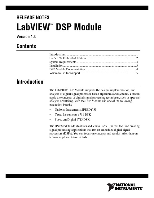
RELEASE NOTESLabVIEW DSP Module™Version 1.0ContentsIntroduction (1)LabVIEW Embedded Edition (2)System Requirements (3)Installation (3)DSP Module Documentation (4)Where to Go for Support (5)IntroductionThe LabVIEW DSP Module supports the design, implementation, andanalysis of digital signal processor-based algorithms and systems. You canapply the concepts of digital signal processing techniques, such as spectralanalysis or filtering, with the DSP Module and one of the followingevaluation boards:•National Instruments SPEEDY-33•Texas Instruments 6711 DSK•Spectrum Digital 6713 DSKThe DSP Module adds features and VIs to LabVIEW that focus on creatingsignal processing applications that run on embedded digital signalprocessors (DSPs). You can focus on concepts and results rather than ontedious implementation details.For the ClassroomThe DSP Module provides students with a positive hands-on DSPexperience that increases their enthusiasm for the subject matter. Studentsuse graphical programming methods to learn DSP fundamentals and todevelop applications for DSP hardware without having to write any C,assembly, or script source. Students benefit from the simplicity andusability of the DSP Module while still being exposed to leading-edgeindustry DSP design tools.For Industry ApplicationsBy using a graphical programming environment for DSP applications, youcan greatly reduce the design and development time while creating moremaintainable and reusable code. Graphical programming for DSPs is moreintuitive than C or assembly so the learning curve is smaller, which allowsyou to expand into new application areas.Application Areas and AnalysisThe DSP Module addresses engineering-related challenges in which DSPsare widely used. In addition to using the DSP Module to teach fundamentalDSP concepts running in real-time on DSP hardware, you also can use theDSP Module to build communication systems, music and speechapplications, and to design complex motor control applications. Additionalapplication areas include the following:•Communication•Modulation and demodulation•FIR (finite impulse response) and IIR (infinite impulse response)filtering•Digital LMS (least-mean-square) filtering•Speech processing and analysis•Noise analysis•Cross correlation•Information processingLabVIEW Embedded EditionThe DSP Module uses LabVIEW 7.1 Embedded Edition, which is a specialedition of LabVIEW 7.1 that installs in a separate directory and does notinterfere with LabVIEW 7.1 Base, Full, or Professional developmentsystems.LabVIEW DSP Module Release System RequirementsThe DSP Module has the following requirements:• A desktop computer with Windows 2000/XP•LabVIEW 7.1 Embedded Edition (included)•One of the following evaluation boards:–National Instruments SPEEDY-33–Texas Instruments 6711 DSK–Spectrum Digital 6713 DSKRefer to the LabVIEW Release Notes, available by selectingStart»Programs»National Instruments»LabVIEW 7.1 EmbeddedEdition»LabVIEW Manuals and opening relnote.pdf, for standardLabVIEW development system requirements.InstallationComplete the following steps to install the DSP Module. After you installthe DSP Module, you must install the driver(s) for your DSP target.1.Log on as an administrator or as a user with administrator privileges.2.Insert the LabVIEW DSP Module CD and follow the instructions thatappear on the screen.Installing the DriversYou must install the appropriate driver for the DSP target. You can find thedrivers in the following locations:•SPEEDY-33—labview embedded\resource\LabVIEWTargets\EmbeddedDSP\SPEEDY33\USB driver•Texas Instruments 6711 DSK—Refer to the Setting Up the TexasInstruments 6711 DSK Target document, available by selectingStart»Programs»National Instruments»LabVIEW 7.1 Embedded Edition»LabVIEW Manuals andopening DSP_6711dsk_setup.pdf, for information about setting upthe 6711 DSK target.•Spectrum Digital 6713 DSK—Refer to the 6713 DSK documentationfrom Spectrum Digital for information about installing the drivers.© National Instruments Corporation3LabVIEW DSP Module Release NotesSetting Up the HardwareRefer to the documentation that came with your DSP hardware forinformation about setting up and configuring the hardware. You can use thedefault configuration for the DSP Module.(6711 DSK Only) Refer to the Setting Up the Texas Instruments 6711 DSKTarget document, available by selecting Start»Programs»National Instruments»LabVIEW 7.1 Embedded Edition»LabVIEWManuals and opening DSP_6711dsk_setup.pdf, for information aboutsetting up the 6711 DSK target.DSP Module DocumentationThe DSP Module includes the following documentation in addition to thisdocument:•VI reference for the VIs the DSP Module adds to LabVIEW isavailable in the LabVIEW Help, available by selecting Help»VI,Function, & How-To Help. In the Contents tab of the LabVIEWHelp, expand the VI and Function Reference book. The DSP ModuleVI reference is in the DSP Module VIs book.•Information about how creating, building, and downloading a DSP VIto a DSP target differs from creating VIs for desktop Windows isavailable in the LabVIEW Help. In the Contents tab of the LabVIEWHelp, expand the DSP Module book.•The Getting Started with the LabVIEW DSP Module manual, availableby selecting Start»Programs»National Instruments»LabVIEW 7.1Embedded Edition»LabVIEW Manuals and openingDSP_Getting_Started.pdf, contains a tutorial that walks youthrough creating, building, downloading, and running DSP VIs.•The readme file, available by selecting Start»Programs»NationalInstruments»LabVIEW 7.1 Embedded Edition»Readme andopening readme_DSP.html, contains known issues.•Examples are available in labview embedded\examples\EmbeddedDSP and can help you get started creating DSP VIs.•The Getting Started with LabVIEW manual, available by selectingStart»Programs»National Instruments»LabVIEW 7.1 EmbeddedEdition»LabVIEW Manuals and opening gtstrtlv.pdf, containsexercises to teach you basic LabVIEW concepts.LabVIEW DSP Module Release Where to Go for SupportThe National Instruments Web site is your complete resource for technicalsupport. At /support you have access to everything fromtroubleshooting and application development self-help resources to emailand phone assistance from NI Application Engineers.National Instruments corporate headquarters is located at11500North Mopac Expressway, Austin, Texas, 78759-3504.National Instruments also has offices located around the world to helpaddress your support needs. For telephone support in the United States,create your service request at /support and follow the callinginstructions or dial 5127958248. For telephone support outside the UnitedStates, contact your local branch office:Australia1800300800, Austria4306624579900,Belgium32027570020, Brazil551132623599,Canada8004333488, China862165557838,Czech Republic420224235774, Denmark4545762600,Finland3850972572511, France330148142424,Germany490897413130, India918051190000,Israel972036393737, Italy3902413091, Japan81354722970,Korea820234513400,Lebanon96101332828,Malaysia1800887710, Mexico018000100793,Netherlands310348433466, New Zealand0800553322,Norway47066907660, Poland48223390150,Portugal351210311210, Russia70957836851,Singapore180********, Slovenia38634254200,South Africa270118058197, Spain34916400085,Sweden460858789500, Switzerland41562005151,Taiwan8860223772222, Thailand6629927519,United Kingdom4401635523545© National Instruments Corporation5LabVIEW DSP Module Release NotesNational Instruments, NI, , and LabVIEW are trademarks of National Instruments Corporation.Refer to the Terms of Use section on /legal for more information about NationalInstruments trademarks. Other product and company names mentioned herein are trademarks or tradenames of their respective companies. For patents covering National Instruments products, refer to theappropriate location: Help»Patents in your software, the patents.txt file on your CD, or/patents.© 2005 National Instruments Corporation. All rights reserved.371298A-01Apr05。
自动化专业常用英语词汇

自动化专业常用英语词汇1. Automation (自动化): The use of technology to control and operate processes without human intervention.2. Control system (控制系统): A system that manages and regulates the behavior of other devices or systems.3. Programmable logic controller (PLC) (可编程逻辑控制器): A digital computer used for automation of electromechanical processes, such as control of machinery on factory assembly lines.4. Sensor (传感器): A device that detects and responds to physical input from the environment, such as temperature, pressure, or light, and converts it into an electrical signal.5. Actuator (执行器): A device that converts control signals into physical action, such as moving a valve or opening a door.6. Human-machine interface (HMI) (人机界面): The point of interaction between a human operator and a machine, typically through a graphical user interface (GUI).7. Process control (过程控制): The use of control systems to manage and optimize industrial processes, such as manufacturing or chemical production.8. Industrial robot (工业机器人): A programmable machine used in manufacturing to perform tasks with high precision and repeatability.9. SCADA (Supervisory Control and Data Acquisition) (监控与数据采集系统): A control system architecture that allows operators to monitor and control industrial processes remotely.10. DCS (Distributed Control System) (分布式控制系统): A control system that consists of multiple autonomous controllers distributed throughout a plant or facility.11. PLC programming (PLC编程): The process of creating and editing the logic and instructions that control the behavior of a programmable logic controller.12. Process optimization (过程优化): The continuous improvement of industrial processes to increase efficiency, reduce waste, and improve product quality.13. Robotics (机器人技术): The branch of technology that deals with the design, construction, operation, and application of robots.14. Industrial automation (工业自动化): The use of control systems and information technologies to optimize industrial processes and increase productivity.15. SCARA robot (Selective Compliance Assembly Robot Arm) (选择性顺应装配机器人): A type of industrial robot with multiple joints that can move in a horizontal plane, typically used for assembly tasks.16. CNC (Computer Numerical Control) (数控): The automation of machine tools that are operated by programmed commands encoded on a computer.17. Motion control (运动控制): The process of controlling the movement of machines or systems, typically using servo motors and feedback sensors.18. PID controller (Proportional-Integral-Derivative controller) (比例-积分-微分控制器): A control loop feedback mechanism used in industrial control systems to regulate processes.19. SCARA robot (Selective Compliance Assembly Robot Arm) (选择性顺应装配机器人): A type of industrial robot with multiple joints that can move in a horizontal plane, typically used for assembly tasks.20. HMI design (人机界面设计): The process of creating user-friendly interfaces for control systems, typically involving the design of graphical displays and interactive controls.21. Mechatronics (机电一体化): The integration of mechanical engineering, electronics, computer science, and control engineering to design and create intelligent systems.22. System integration (系统集成): The process of combining different components or subsystems into a single cohesive system that functions as a whole.23. Robotics vision system (机器人视觉系统): The use of cameras and image processing algorithms to enable robots to perceive and interpret visual information.24. Industrial networking (工业网络): The use of communication protocols and technologies to connect and exchange data between devices in an industrial environment.25. Fault diagnosis (故障诊断): The process of identifying and analyzing faults or malfunctions in a system to determine the cause and recommend appropriate solutions.26. Safety interlock system (安全互锁系统): A system that prevents unsafe conditions or operations by enforcing certain conditions or sequences of actions.27. Industrial communication protocols (工业通信协议): Standardized methods and rules for exchanging data between devices in an industrial automation system.28. Motion planning (运动规划): The process of determining the optimal trajectory or path for a robot or machine to follow to complete a task.29. Real-time control (实时控制): The ability of a control system to respond to input and produce output within a guaranteed time frame.30. Industrial process simulation (工业过程仿真): The use of computer models and simulations to replicate and analyze industrial processes for optimization and troubleshooting.以上是自动化专业常用英语词汇的详细介绍,希望对您有所帮助。
计算机科学英语词汇大全掌握计算机科学领域的专业术语和常见缩略词

计算机科学英语词汇大全掌握计算机科学领域的专业术语和常见缩略词在计算机科学领域,掌握专业术语和常见缩略词是非常重要的,这有助于更好地理解和沟通。
本文将为您整理一份计算机科学英语词汇大全,以便您学习和掌握这些专业术语。
以下是常见的计算机科学英语词汇及其解释:1. Algorithm(算法): A set of predefined rules or instructions used to solve a specific problem or perform a specific task in a computer program.2. Binary(二进制): A numbering system that consists of only two digits, 0 and 1. It is widely used in computer systems as the fundamental language for representing data and performing calculations.3. Compiler(编译器): A software tool that translates high-level programming languages into machine language or assembly language, which can be directly executed by a computer.4. Database(数据库): A structured collection of data that is organized and stored in a computer system. It allows users to easily retrieve, update, and manage data efficiently.5. Encryption(加密): The process of converting data into a form that is unreadable by unauthorized users. Encryption is used to ensure the security and privacy of sensitive information.6. Firewall(防火墙): A network security device that monitors and controls incoming and outgoing network traffic based on predeterminedsecurity rules. It acts as a barrier between a trusted internal network and untrusted external networks.7. HTML (Hypertext Markup Language)(超文本标记语言): The standard markup language used for creating and structuring web pages. It defines the structure and layout of the content on a webpage.8. GUI (Graphical User Interface)(图形用户界面): A visual interface that allows users to interact with a computer or software using graphical elements, such as windows, icons, buttons, and menus.9. Kernel(内核): The core component of an operating system that manages system resources and provides low-level services to other software applications.10. Machine Learning(机器学习): A branch of artificial intelligence that enables computer systems to learn and improve from experience without being explicitly programmed. It focuses on the development of algorithms that can analyze and interpret data to make predictions or decisions.11. Network(网络): A collection of interconnected devices, such as computers, servers, routers, and switches, that allows for the exchange of data and resources.12. Object-Oriented Programming(面向对象编程): A programming paradigm that organizes software design around objects, rather than logic and procedures. It emphasizes the reusability, modularity, and extensibility of code.13. Protocol(协议): A set of rules and standards that govern the communication between devices on a network. Protocols ensure that data is transmitted and received correctly.14. Query(查询): A request for specific information or data from a database using a query language, such as SQL (Structured Query Language).15. RAM (Random Access Memory)(随机存取存储器): A type of computer memory that stores data that is being actively used by a computer program. It allows for faster access to data compared to other types of storage.16. Software Development(软件开发): The process of designing, coding, testing, and maintaining software applications and systems. It involves various stages, such as requirements analysis, design, implementation, and deployment.17. TCP/IP (Transmission Control Protocol/Internet Protocol)(传输控制协议/互联网协议): A set of networking protocols that allows computers to communicate and exchange data over the internet. It provides a reliable and standardized method for transmitting data packets.18. Virtual Reality(虚拟现实): A computer-generated simulation of a three-dimensional environment that can be interacted with and explored by a user. It typically involves the use of specialized hardware, such as headsets and motion controllers.19. Web Development(网站开发): The process of creating and maintaining websites and web applications. It includes tasks such as webdesign, web content development, client-side scripting, and server-side scripting.20. XML (eXtensible Markup Language)(可扩展标记语言): A markup language that is designed to store and transport data. It is widely used for representing and exchanging structured data over the internet.这些是计算机科学中的一些常见英语词汇和术语。
关于一些MATLAB用法和器件名称的中英文翻译

MATLAB - The Language Of Technical ComputingMATLAB is a high-level language and interactive environment that enables you to perform computationally intensive tasks faster than with traditional programming languages such as C, C++, and Fortran. You can use MATLAB in a wide range of applications, including signal and image processing, communications, control design, test and measurement, financial modeling and analysis, and computational biology. Add-on toolboxes (collections of special-purpose MATLAB functions, available separately) extend the MATLAB environment to solve particular classes of problems in these application areas. MATLAB provides a number of features for documenting and sharing your work. You can integrate your MATLAB code with other languages and applications, and distribute your MATLAB algorithms and applications.MATLAB has key featuers as follows:(1)High-level language for technical computing (2)Development environment for managing code, files, and data(3)Interactive tools for iterative exploration, design, and problem solving 4)Mathematical functions for linear algebra, statistics, Fourier analysis, filtering, optimization, and numerical integration (5)2-D and 3-D graphics functions for visualizing data (6)Tools for building custom graphical user interfaces (7)Functions for integrating MATLAB based algorithms with external applications and languages, such as C, C++, Fortran, Java, COM, and Microsoft ExcelThe MATLAB language supports the vector and matrix operations that are fundamental to engineering and scientific problems. It enables fast development and execution. With the MATLAB language, you can program and develop algorithms faster than with traditional languages because you do not need to perform low-level administrative tasks, such as declaring variables, specifying data types, and allocating memory. In many cases, MATLAB eliminates the nee d for ‘for’ loops. As a result, one line of MATLAB code can often replace several lines of C or C++ code. At the same time, MATLAB provides all the features of a traditional programming language, including arithmetic operators, flow control, data structures, data types, object-oriented programming (OOP), and debugging features. MATLAB lets you execute commands or groups of commands one at a time, without compiling and linking, enabling you to quickly iterate to the optimal solution. For fast execution of heavy matrix and vector computations, MATLAB uses processor-optimized libraries. For general-purpose scalar computations, MATLAB generates machine-code instructions using its JIT (Just-In-Time) compilation technology. This technology, which is available on most platforms, provides execution speeds that rival those of traditional programming languages. MATLAB includes development tools that help you implement your algorithm efficiently. These include the following: MATLAB Editor - Provides standard editing and debugging features, such as setting breakpoints and single stepping. M-Lint Code Checker - Analyzes your code and recommends changes to improve its performance and maintainability. MATLAB Profiler - Records the time spent executing each line of code. Directory Reports- Scan all the files in a directory and report on code efficiency, file differences, file dependencies, and code coverage。
关于环境的设计理念英语

关于环境的设计理念英语Environmental design is the process of creating spaces that are environmentally sustainable, functional, and aesthetically pleasing. It involves considering the impact of design decisions on the environment, as well as the needs and desires of the people using the space. There are several key design principles that guide environmentally-friendly design:1. Sustainable materials: The use of sustainable materials is a fundamental principle of environmental design. This involves selecting materials that are renewable, recycled, or have a low environmental impact. For example, using timber from responsibly managed forests or recycled steel instead of virgin materials.2. Energy efficiency: Designing spaces that minimize energy consumption is another important aspect of environmental design. This can include incorporating natural lighting and ventilation systems, as well as using energy-efficient appliances and fixtures. Additionally, renewable energy sources such as solar panels or wind turbines can be integrated into the design.3. Water conservation: Conserving water is crucial for environmental sustainability. Designing spaces that minimize water usage through efficient fixtures, rainwater harvesting systems, and water-efficient landscaping can help reduce water waste.4. Biodiversity and ecosystem protection: Environmental design should prioritize the preservation and enhancement of local ecosystems. This can be achieved by incorporating native plantspecies, creating habitats for wildlife, and minimizing disruption to natural waterways and landforms.5. Waste reduction and recycling: Designing spaces with a focus on waste reduction and recycling is essential for minimizing environmental impact. This can involve incorporating recycling bins and composting facilities, as well as designing spaces that promote the use of reusable products and materials.6. Accessibility and inclusivity: Environmental design should prioritize the needs of all users, including those with disabilities. By incorporating universal design principles, such as wheelchair accessibility and clear wayfinding systems, spaces can be made more inclusive and welcoming for everyone.7. Aesthetics and user experience: While environmental sustainability is a key focus of environmental design, aesthetics and user experience should not be overlooked. By creating spaces that are visually appealing and functional, users are more likely to engage with the environment in a positive way, leading to a greater appreciation for environmental issues.In conclusion, environmental design is a holistic approach that considers the environmental, social, and economic aspects of design. By incorporating sustainable materials, energy efficiency, water conservation, biodiversity protection, waste reduction, accessibility, and aesthetic appeal, designers can create spaces that are not only visually pleasing but also environmentally sustainable.。
程序设计英语怎么说

程序设计英语怎么说程序设计是给出解决特定问题程序的过程,是软件构造活动中的重要组成部分。
随着硬件技术的飞速发展和软件规模的日益庞大,程序的结构、可维护性、复用性、可扩展性等因素日益重要。
那么你知道程序设计用英语怎么说吗?接下来跟着店铺来学习一下吧。
程序设计的英语说法:Program design程序设计相关英语表达:面向对象程序设计Programmation orientée objet程序设计语言列表 Liste des langages de programmation程序设计方法学 software development methodology结构化程序设计 Structured Program Design自动程序设计 self-programming程序设计技术 program design technology程序设计的英语例句:1. In some programming languages, a variable whose value is a character string.在某些程序设计语言中, 一种值为字符串的变量.2. An instruction designed to facilitate the programming of string manipulations.为便于字符串处理的程序设计而设立的一种指令.3. The process of writing instructions in a programming language.用程序设计语言编写指令的过程.4. Fortran is perhaps the most widely used high level programming language.Fortran语言可能是用得最广的高级程序设计语言.5. In DPPX, a queue in the printer - sharing environment.在分布式处理程序设计执行程序(DPPX)中, 处于打印机共享环境中的一种队列.6. In computer programming, a jump instruction.计算机程序设计中的一种跳转指令.7. A programming language that reflects the concepts of object - oriented programming. Example: SMALLTALK and C 000? + 00.一种反映面向对象编程概念的程序设计语言. 例如SMALLTALK 和C000? +00.8. An abbreviation for formula calculation language, a high - level programming language not too widely used.公式计算语言的简称, 应用不太广泛的一种高级程序设计语言.9. A programming language based on ALGOL and designed for non - numeric manipulation of mathematical expressions.一种以ALGOL语言为基础,为数学表达式进行非数值操作而设计的程序设计语言.10. Finally, the scheme, function and program flow of subsystems are designed.最后本文对铁路春运子系统进行了方案设计、功能设计和程序设计.11. Dance robot programming for the U.S. as a reference procedure.舞蹈机器人的程序设计,供大家一个参考的程序.12. Visual ( visualization ): the use of graphical user interface ( GUI ) programming methods.Visual ( 可视化 ): 采用图形用户界面 ( GUI ) 的程序设计方法.13. Knowledge of a higher programming language to simulate and solve technical problems.能应用高级程序设计语言模拟和解决技术问题.14. Belonging to network programming, client and server for file transfer!属于网络程序设计, 客户端与服务器进行文件传输!15. The backtracking mechanism is an important facility for programming in logic.回溯机制是逻辑程序设计的重要设施.。
设计环境艺术设计英语作文

设计环境艺术设计英语作文Environment art design is a form of art that integrates with the natural or built environment to create animmersive and interactive experience for the audience.It can take many forms, such as large-scale installations, outdoor sculptures, or interactive digital projections, and it often blurs the boundaries between art, architecture, and landscape design.Environment art design aims to provoke emotional and sensory responses from the audience, challenging their perceptions of space, time, and the environment around them.By using a combination of materials, textures, colors, and lighting, environment art design creates a unique and dynamic experience that changes with the time of day, weather, and seasons.It encourages people to engage with their surroundingsin new and unexpected ways, fostering a deeper connection to the environment and promoting environmental awareness and sustainability.Environment art design also has the potential to revitalize public spaces, turning neglected or underused areas into vibrant and inspiring places for people to gather, socialize, and appreciate the beauty of their surroundings.In conclusion, environment art design has the power to transform our relationship with the environment, creating meaningful and memorable experiences that inspire us to see the world in a different light.。
外文翻译--机械设计简介

外文原文Introduction to Mechanical DesignMechanical design is the application of science and technology to devise new or improved products for the purpose of satisfying human needs. It is a vast field of engineering technology which not only concerns itself with the original conception of the product in terms of its size, shape and construction details, but also considers the various factors involved in the manufacture, marketing and use of the product.People who perform the various functions of mechanical design are typically called designers, or design engineers. Mechanical design is basically a creative activity. However, in addition to being innovative, a design engineer must also have a solid background in the areas of mechanical drawing, kinematics, dynamics, materials engineering, strength of materials and manufacturing processes.As stated previously, the purpose of mechanical design is to produce a product which will serve a need for man. Inventions, discoveries and scientific knowledge by themselves do not necessarily benefit people; only if they are incorporated into a designed product will a benefit be derived. It should be recognized, therefore, that a human need must be identified before a particular product is designed.Mechanical design should be considered to be an opportunity to use innovative talents to envision a design of a product, to analyze the system and then make sound judgments on how the product is to be manufactured. It is important to understand the fundamentals of engineering rather than memorize mere facts and equations. There are no facts or equations which alone can be used to provide all the correct decisions required to produce a good design. On the other hand, any calculation made must be done with the utmost care and precision. For example, if a decimal point is misplaced, a otherwise acceptable design may mot function.Good designs require trying mew ideas and being willing to take a certain amount of risk, knowing that if the mew idea does not work the existing method can bereinstated. Thus a designer must have patience, since there is no assurance of success for the time and effort expended. Creating a completely new design generally requires that many old and well-established methods be thrust aside. This is not easy since many people cling to familiar ideas, techniques and attitudes. A design engineer should constantly search for ways to improve an existing product and must decide what old, proven concepts should be used and what new, untried ideas should be incorporated.New designs generally have “bugs” or unforeseen which must be worked out before the superior characteristics of the new designs can be enjoyed. Thus there is a chance for a superior product, but only at higher risk. It should be emphasized that, if a design does not warrant radical new methods, such methods should not be applied merely for the sake of change.During the beginning stages of design, creativity should be allowed to flourish without a great number of constraints. Even though many impractical ideas may arise, it is usually easy to eliminate then in the early stages of design before firm details are required by manufacturing. In this way, Innovative ideas are not inhibited. Quite often, more than one design is developed, up to the point where they can be compared against each other. It is entirely possible that the design which is ultimately accepted will use ideas existing in one of the rejected designs that did not show as much overall promise.Psychologists frequently talk about trying to fit people to the machines they operate. It is essentially the responsibility of the engineer to strive to fit machines to people. This is not an easy task, since there is really no average person for which certain operating dimensions and procedures are optimum.Another important point which should be recognized is that a design engineer must be able to communicate ideas to other people if they ate to be incorporated. Communicating the design to others is the final, vital step in the design process. Undoubtedly many great designs, inventions, and creative works have been lost to mankind simply because the originators were unable or unable or unwilling to explain their accomplishments to others. Presentation is a selling job. The engineer whenpresenting a new solution to administrative, management, or supervisory persons, is attempting to sell or to prove to them that this solution is a better one. Unless this can be done successfully, the time and effort spent on obtaining the solution have been largely wasted.Basically, there ate only three means of communication available to us. These are the written, the oral, and the graphical forms. Therefore the successful engineer will be technically competent and versatile in all three forms of communication. A technically competent person who lacks ability in any one of these forms is severely handicapped. If ability in all three forms is lacking, no one will ever know how competent that person is!The competent engineer should not be afraid of the possibility of not succeeding in a presentation. In fact, occasional failure should be expected because failure or criticism seems to accompany every really creative idea. There is a great deal to learn from a failure, and the greatest gains ate obtained by those wiling to risk defeat. In the final analysis, the real failure would lie in decoding not to make the presentation at all. To communicate effectively, the following questions must be answered:1、Does the design really serve a human need?2、Will it be competitive with existing products of rival companies?3、It is economical to profit?4、Can it be readily maintained?5、Will it sell and make a profit?Only time will provide the true answers to the preceding questions, but the product should be designed, manufactured and marketed only with initial affirmative answers. The design engineer also must communicate the finalized design to manufacturing through the use of detail and assembly drawings.Quite often, a problem will occur during the manufacturing cycle. It may be that a exchange is required in the dimensioning or tolerancing of a part so that it can be more readily produced. This falls in the category of engineering changes which must be approved by the design engineer so that the product function will not be adversely affected. In other cases, a deficiency in the design may appear during assembly ortesting just prior to shipping.Engineering design is a systematic process by which solutions to the needs of humankind are obtained. The process is applied to problems (needs) of varying complexity. For example, mechanical engineers will use the design process to find an effective, efficient method to convert reciprocating motion to circular motion for the drive train in an internal combustion engine; electrical engineers will use the process to design electrical generating systems using falling water as the power source; and materials engineers use the process to design ablative materials which enable astronauts to safely the earth’s atmosphere.The va st majority of complex problems in today’s high technology society depend for solution not on a single engineering discipline, but on teams of engineers, scientists, environmentalists, economists, sociologists, and legal personnel. Solutions are not only dependent upon the appropriate applications of technology but also upon public sentiment, government regulations and political influence. As engineers we are empowered with the technical expertise to develop new and improved products and systems, but at the same time we must be increasingly aware of the impact of our actions on society and the environment in general and work conscientiously toward the best solution in view of all relevant factors.Design is the culmination of the engineering educational process; it is the salient feature that distinguishes engineering from other professions.A formal definition of engineering design is found in the curriculum guidelines of the Accreditation Board for Engineering and Technology (AENT). ABEN accredits curricula in engineering schools and derives its membership from the various engineering professional societies. Each accredited curriculum has a well-deigned design component which falls within the ABEN guideline. The ABEN statement on design reads as follows:Engineering design is the process of devising a system, component, or process to meet desired needs. It is a decision making process (often iterative ), in which the basic sciences, mathematic, and engineering sciences are applied to convert resources optimally to meet a stated objective. Among the fundamental elements of the designprocess are the establishment of objectives and criteria, synthesis, analysis, construction, testing, and evaluation. The engineering design component of a curriculum must include most of the following features: development of student creativity, use of open-ended problems, development and use of modern design theory mad methodology, formulation of design problem statements and specifications, consideration of alternative solutions, feasibility considerations, production processes, concurrent engineering design, and detailed system descriptions. Further, it is essential to include a variety of realistic constraints such as economic factors, safety, reliability, aesthetics, ethics, and social impact.If anything can be said about the last half of the twentieth century, it is that we have had an explosion of information. The amount of data that can be uncovered on most subjects is overwhelming. People in the upper levels of most organizations have assistants who condense most of the things that they must read, hear, or watch. When you begin a search for information, be prepared to scan many of your sources and document their location so that you can find them easily if the date subsequently appear to be important.Some of the sources that are available include the following:1、Exiting solutions. Much can be learned from the current status of solutions toa specific need if actual products can be located, studied and, in some cases, purchased for detailed analysis. An improved solution or an innovative new solution new solution cannot be found unless the existing solutions are thoroughly understood.2、Your library. Many universities have courses that teach you how to use your library. Such courses are easy when you compare them with those in chemistry and calculus, but their importance should not be underestimated. There are many sources in the library that can lead you to the information that you are seeking. You may find what you need in an index such as the Engineering Index. There are many other indexes that provide specialized information. The nature of your problem will direct which ones may be helpful to you. Don’t hesitate to ask for assistance from the librarian. You should use to advantage the computer databases found in libraries and often available through CD-ROM technology.3、Professional organizations. The American Society of Mechanical Engineers isa technical society that will be of interest to students majoring in mechanical engineering. Each major in your college is associated with not one but often several such societies. The National Society of Professional Engineers is an organization that most engineering students well eventually join, as well as at least one technical society such as the society of manufacturing engineers, the American Society of civil engineers (ASCE), or any one of dozens that serve the technical interests of the host of specialties with which professional practices seem most closely associated. May engineers are members of several associations and societies.4、Trade journals. They are published by the hundreds, usually specializing in certain classes of products and services. Money and economics are part of engineering design and decision making. We live in a society that is based on economics and competition. It is no doubt true that many good ideas never get tried because they are deemed to be economically infeasible. Most of us have been aware of this condition in our daily lives. We started with our parents explaining why we could not have some item that we wanted because it cost too much. Likewise, we will not put some very desirable component into our designs because the value gained will not return enough profit in relation to its cost.Industry is continually looking for new products of all types. Some are desired because the current product is not competing well in the marketplace. Others are tried simply because it appears that people will buy them. How do manufacturers know that a new product will be popular? They seldom know with certainty. Statistics is an important consideration in market analysis. Most of you will find that probability and statistics are an integral part of your chosen engineering curriculum. The techniques of this area of mathematics allow us to make inferences about how large groups of people react based on the reactions of a few.中文译文机械设计简介机械设计是为了满足人类需要而制定出的新产品或者改进旧产品时对科学与技术的应用。
resizebar原理

resizebar原理Resizing bars, also known as resizebars, are a fundamental component of graphic user interfaces in software applications. These bars allow users to adjust the size of various elements within the graphical interface, such as windows, panes, or panels. The principle behind resizebars is to provide users with the flexibility to customize the layout of the interface according to their preferences and requirements. By dragging the resizebar, users can expand or contract the size of the associated element, enabling them to optimize their workspace and enhance their overall user experience.调整大小条,也称为resizebars,是软件应用程序中图形用户界面的基本组件。
这些条允许用户调整图形界面中各种元素的大小,如窗口、窗格或面板。
resizebar的原理是为用户提供灵活性,根据其偏好和需求定制界面的布局。
通过拖动resizebar,用户可以扩展或收缩相关元素的大小,使他们可以优化其工作区,并增强其整体用户体验。
From a technical standpoint, resizebars are typically implemented using a combination of user interface components and event handling mechanisms. The user interface components consist ofgraphical elements that visually represent the resizebar, such as a draggable handle or a delineated area on the interface. These components are designed to respond to user input, specifically mouse interactions, enabling users to interact with the resizebar through drag-and-drop actions. Meanwhile, the event handling mechanisms are responsible for detecting and processing the user input, translating the drag-and-drop actions into resizing operations, and updating the graphical interface accordingly.从技术角度来看,resizebars通常是使用用户界面组件和事件处理机制的组合实现的。
关于设计的英语作文还要有图

关于设计的英语作文还要有图英文回答:Design is a fundamental aspect of our lives, shapingour experiences, informing our decisions, and enhancing our well-being. It encompasses various disciplines, including architecture, fashion, furniture, and graphic design, each with its unique techniques and principles.Design plays a pivotal role in problem-solving, seeking solutions that not only meet functional requirements butalso elevate user experiences. By considering factors such as ergonomics, aesthetics, and usability, designers create products, spaces, and systems that are not just effective but also aesthetically pleasing and intuitive to use.One of the most significant aspects of design is its ability to communicate. Through visual language, designers convey messages, evoke emotions, and shape perceptions. Whether it's a billboard advertisement, a website interface,or an architectural masterpiece, design serves as apowerful form of expression and communication.Furthermore, design has a profound impact on society, contributing to its cultural and economic development. Innovative designs have the potential to revolutionize industries, create new markets, and improve the overall quality of life. By fostering creativity, innovation, and collaboration, design enables progress and transforms our world for the better.中文回答:设计作为我们生活中的一个基本组成部分,塑造着我们的体验,指导着我们的决定,并提升着我们的幸福感。
Autodesk Inventor 3D模型和数字原型的介绍说明书
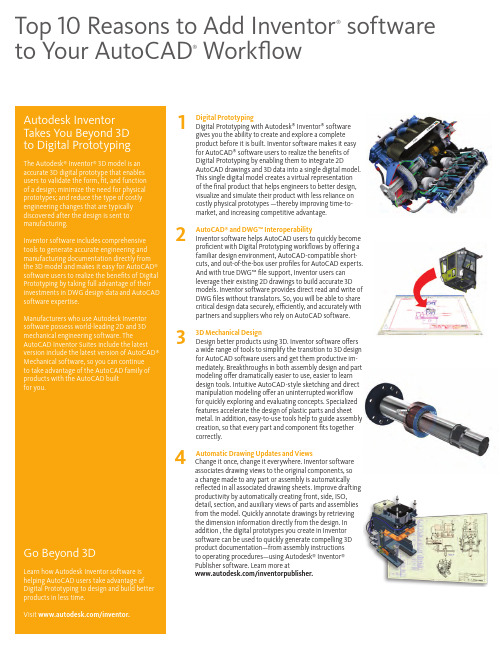
1 D igital Prototyping Digital Prototyping with Autodesk ® Inventor ® software gives you the ability to create and explore a complete product before it is built. Inventor software makes it easy for AutoCAD ® software users to realize the benefits of Digital Prototyping by enabling them to integrate 2D AutoCAD drawings and 3D data into a single digital model. This single digital model creates a virtual representation of the final product that helps engineers to better design, visualize and simulate their product with less reliance on costly physical prototypes —thereby improving time-to-market, and increasing competitive advantage.2 A utoCAD ® and DWG™ Interoperability Inventor software helps AutoCAD users to quickly become proficient with Digital Prototyping workflows by offering a familiar design environment, AutoCAD-compatible short-cuts, and out-of-the-box user profiles for AutoCAD experts. And with true DWG™ file support, Inventor users can leverage their existing 2D drawings to build accurate 3D models. Inventor software provides direct read and write of DWG files without translators. So, you will be able to share critical design data securely, efficiently, and accurately with partners and suppliers who rely on AutoCAD software.3 3D Mechanical Design Design better products using 3D. Inventor software offers a wide range of tools to simplify the transition to 3D designfor AutoCAD software users and get them productive im-mediately. Breakthroughs in both assembly design and partmodeling offer dramatically easier to use, easier to learndesign tools. Intuitive AutoCAD-style sketching and directmanipulation modeling offer an uninterrupted workflowfor quickly exploring and evaluating concepts. Specializedfeatures accelerate the design of plastic parts and sheetmetal. In addition, easy-to-use tools help to guide assemblycreation, so that every part and component fits togethercorrectly.4 Automatic Drawing Updates and ViewsC hange it once, change it everywhere. Inventor softwareassociates drawing views to the original components, soa change made to any part or assembly is automaticallyreflected in all associated drawing sheets. Improve draftingproductivity by automatically creating front, side, ISO,detail, section, and auxiliary views of parts and assembliesfrom the model. Quickly annotate drawings by retrievingthe dimension information directly from the design. Inaddition , the digital prototypes you create in Inventorsoftware can be used to quickly generate compelling 3Dproduct documentation—from assembly instructions to operating procedures—using Autodesk ® Inventor ®Publisher software. Learn more at/inventorpublisher.Top 10 Reasons to Add Inventor ®software to Your AutoCAD ®WorkflowAutodesk, AutoCAD, Autodesk Inventor, DWG, and Inventor are registered trademarks or trademarks of Autodesk, Inc., in the USA and/or other coun-tries. All other brand names, product names, or trademarks belong to their respective holders. Autodesk reserves the right to alter product offerings and specifications at any time without notice, and is not responsible for typographical or graphical errors that may appear in this document. © 2010 Autodesk, Inc. All rights reserved. 5 D esign AutomationA utodesk Inventor software features rules-based design and automation tools to accelerate design by automating common tasks, enabling engineers to focus on design intent rather than manually modeling geometry. Inventor software captures the functional requirements of a design to drive the automatic creation of intelligent components and accelerate design cycles. Fully integrated Inventor iLogic technology can dramatically simplifies rules-based design to help any Inventor user—even those with little or no programming experience—to define complex product configurations, increase engineering productivity, and optimize designs.6 S tate-of-the-Art VisualizationQuickly and easily create stunning renderings, animations, and presentations that improve communication with your design partners and customers. Autodesk Inventor software provides state-of-the-art visualization, illustration, and animation tools directly in the default workspace, giving you a realistic representation of your design at all times. Dynamic shading, precise lighting control, and the included library of high-resolution textures make it easy to create photo-realistic scenes of your final products in actual environments.7 A utomatic Bill of MaterialsCreate automated and associative parts lists and bills of materials (BOMs) that are developed specifically for manufacturing. Support is included for multiple parts lists per drawing, col-lapsible assemblies, and automatic recognition of standard parts. With automatic updating, changes ripple through the entire design to help keep everyone on schedule with accurate part counting, identification, and ordering. Features can be customized to match current com-pany practices, and BOM data can be exported to a variety of enterprise resource planning (ERP) systems.8 E asy-to-Use SimulationPredict how your designs will work under real-world conditions before they’re built. Autodesk ® Inventor ® Professional software provides easy-to-use motion simulation and stress analysis tools to help you create better-quality parts and avoid field failures. A comprehensive simulation environment provides support for motion simulation and static and modal finite element analysis (FEA) of parts, assemblies and load-bearing frames. Autodesk Inventor Professional also includes Moldflow ® plastic simulation tools to validate the design of injection molds for plastic parts. And, because these tools are tightly integrated with the 3D design software, it’s practical and cost-effective to employ simulation throughout the design process.9 Pipe and Cable Routing Autodesk Inventor Professional software provides the power to quickly and accurately add routed systems, tube and pipe runs to 3D designs. Routed designs automatically comply with user-defined design rules to reduce errors and save time. In addition, the cable and wire har-ness routing functionality helps mechanical engineers to integrate electrical controls into 3D mechatronic product designs. As with all Inventor files, the assembly drawings automatically update whenever the routing model is modified.10I ntegrated Data ManagementAutodesk Inventor software includes integrated data management with Autodesk ® Vault software, a centralized application for workgroups that securely stores and manages work-in-progress design data and related documents. For additional functionality, such as revision control, file and folder security, and BOM and ECO management, learn more about the complete Vault family of products. /vaultfamily.Experience for yourself how easy it is to add Inventor to your AutoCAD workflow. Test driveAutodesk Inventor software and start realizing the benefits of Digital Prototyping today.To order your free 30-day Trial of Autodesk Inventor Professional software, visit /inventortrial。
- 1、下载文档前请自行甄别文档内容的完整性,平台不提供额外的编辑、内容补充、找答案等附加服务。
- 2、"仅部分预览"的文档,不可在线预览部分如存在完整性等问题,可反馈申请退款(可完整预览的文档不适用该条件!)。
- 3、如文档侵犯您的权益,请联系客服反馈,我们会尽快为您处理(人工客服工作时间:9:00-18:30)。
prede ned building blocks interactively. On the contrary, they often give up generality in favor of restricting appearance and functionality to a particular interface style, a so-called \look and feel", e.g., Open Look SUN 90] or OSF/Motif OSF 90]. Although object-oriented approaches employed by many high-level toolkits have achieved substantial improvement, constructing user interfaces with toolkits still needs high programming skills. Therefore, building graphical user interfaces for sophisticated applications de nitely needs more powerful programming tools. User Interface Management Systems (UIMS) denote tools that support the development of user interfaces separately from the underlying applications Pfa 85]. Many examples of UIMS are based on the formal description of user interfaces. Building user interfaces employing graphical visualization and direct manipulation techniques, however, may be rather characterized as a design activity than giving formal descriptions or just program coding. For these kinds of tasks, the idea of construction kits and design environments raised special interest over the last years FischerLemke 88]. Especially in the domain of user interface construction and design, interactive programming tools using visual programming techniques have been successfully employed Myers 90, Myers et al. 90]. So-called user interface builders can be very helpful for building interfaces by means of direct manipulation, especially as far as visual properties are concerned. However, they are typically restricted to a xed set of prede ned interface elements and mostly are very poor when a slightly modi ed appearance or functionality is required. We have implemented a layered architecture of interactive tools for building, inspecting, and modifying graphical user interfaces for the X Window System, comprising user interface toolkits as well as visual programming tools integrated in an interactive programming environment. Their design and implementation follow the concepts of the Usit system Herczeg 89], developed by the research group Inform at the University of Stuttgart, and make them available on a more standardized software platform. These concepts have been further developed towards a design environment for user interfaces.
User Interface Builders, Construction Kits, Design Environments, Object-Oriented Programming, Visual Programming
1 Introduction
With the availability of window systems like the X Window System Schei erGettys 86] on di erent computer platforms, the use of graphical user interfaces in di erent application domains is permanently increasing. These systems basically provide a communication protocol for window server and client programs, as for instance the X protocol Schei er 89], and low-level programming interfaces, such as Xlib Nye 88], which are open to very di erent interface styles. Because of their generality these programming interfaces are not appropriate for direct application; they rather form the basis for higher-level tools. Especially for building graphical user interfaces, object-oriented programming techniques proved to be very useful Barth 86]. User interface toolkits are object-oriented programming interfaces that provide a higher abstraction level. They may be basically characterized as a library of common user interface elements like buttons, menus, or scrollbars, also called widgets, which are used as building blocks for graphical user interfaces. Over the last years, numerous toolkits emerged, as for instance the X Toolkit and the various widget sets built on top of it NyeO'Reilly 90]. Mostly, these toolkits are di cult to use and do not provide appropriate means for de ning new building blocks, let alone modifying 1
2 A Layered Architecture for User Interface Design
Figure 1 shows the layered architecture of a user interface design environment for the X Window System. The layers correspond to di erent abstraction levels on which user interfaces may be constructed and modi ed Herczeg et al. 91]. The components have been implemented in Common Lisp and Clos, the Common Lisp Object System.
A Design Environment foБайду номын сангаас Graphical User Interfaces
Jurgen Herczeg
Research Group drUId Department of Computer Science, University of Stuttgart Breitwiesenstr. 20-22, D-7000 Stuttgart 80, Federal Republic of Germany Tel: +49 711 7816 364 Fax: +49 711 780 10 45 E-Mail: herczeg@informatik.uni-stuttgart.de Today, building user interfaces for sophisticated applications may be characterized as a design activity that needs powerful programming tools. Many of the existing tools are either too low-level or too restricted. We will describe a layered architecture of object-oriented user interface design tools, comprising user interface toolkits as well as visual programming tools for building, inspecting, and modifying graphical user interfaces interactively. They correspond to di erent abstraction levels on which user interfaces may be constructed and modi ed by user interface designers or even end users. We will further argue that these tools are even more e ective when they are integrated within a visual programming environment together with general browsing and tracing components. Keywords: User Interface Design, Graphical User Interfaces, User Interface Toolkits,