HSMK-A101-Q3WJ1中文资料
Met One Instruments BX-301 中文名字说明书

BX-301M ID R ANGE M EMBRANEI NSTRUCTIONSMet One Instruments, Inc.1600 NW Washington Blvd.Grants Pass, Oregon 97526Telephone 541-471-7111Facsimile 541-471-71161 About the BX-301 Mid-Range MembraneThe BX-301 is a special purpose mid-range membrane foil assembly which may be used to verify the linearity of the BAM-1020 mass calculation system. The mass calculation of the BAM-1020 is inherently linear in nature, and therefore it is unnecessary to audit a mid range point in the vast majority of applications. The BX-301 is provided only as a convenience to certain customers who may be required to perform the check by local regulations.The BAM-1020 unit performs a span membrane check automatically every hour using it’s built-in membrane with a mass of approximately 0.800 mg/cm2. The BX-301 allows the user to periodically perform an additional span check at about 0.500 mg/cm2.The BX-301 membrane is a fragile assembly, and must be handled very carefully. Any puncture or damage to the foil surface will render the part useless. Any dirt or contamination on the foil surface will be measured as mass, and will also invalidate the measurement. This assembly must be protected and stored in a safe location away from heat and direct sunlight.2 Mid Range Span Check ProcedureNote: The BAM-1020 unit must be powered on and warmed up for at least one hour before performing the test. The pump does not need to be running during warm-up.1. Remove the ten case cover screws and washers from the BAM-1020. You will needto access the inside of the unit later to complete the test.2. Verify the factory determined ABS value of the BAM-1020 unit. This can be found inthe SETUP > CALIBRATE menu or on the calibration certificate for the unit. This is the expected mass of the span membrane foil in the unit, and will be about 0.800mg/cm2.3. Enter the TEST > CALIBRATE menu on the user interface. This is the screen thatwill be used for the membrane tests. See Section 7.13 of the BAM-1020 manual.The CALIBRATE Test Screen4. Press the START soft key to start a membrane measurement with the existing foil.The test will take about eight minutes to complete. The unit will then display themeasured value of the span membrane foil as the CAL MASS M value. Comparethis value with the ABS (expected) value and record the results. These shouldtypically match within a few micrograms. Note: If these values disagree by 5% ormore, then there is something wrong with the unit such as a dirty membrane or an incorrect ABS value. Do not proceed with the test if the BAM-1020 is not reading its own membrane correctly.5. Remove the BAM case cover. Locate the membrane assembly on the inside of theunit, and the brass raceway in which the membrane assembly slides forwards and backwards. Remove the small dust cover (two small screws and washers). Set the parts aside.MembraneMotorDust CoverMembraneAssemblyMembraneControl ArmThe Membrane Assembly Inside the BAM-10206. Carefully remove the existing membrane from the unit: Pull back the control armagainst it’s spring pressure until you can slide the membrane from the back of the assembly. There should be an expected mass value printed on the back of the mid-range membrane. Record this value. Insert the mid-range membrane foil exactly as the other membrane was installed. Note: Make sure the pin of the membrane is in the slot of the control arm, or the test will not work. Swapping membranes is a very simple matter once you know what you are doing.7. Press the START soft-key to start the test with the mid-range membrane in place.When the unit has calculated and displayed the new CAL MASS M value, record it and start the test over. Perform the test two more times and take an average of the three measured values. This average must be within 5% of the expected valueprinted on the membrane, and will typically be within a few micrograms. Record the results.8. Remove the mid-range membrane and replace the original part. Reinstall the smalldust cover and the main case cover of the BAM-1020.BAM-1020 Membrane Foil Mid-Range Linearity CheckTest Results Record:Test Performed By:Test Date:BAM-1020 Serial Number:Expected ABS Value:mg/cm2Measured Mass of Existing Foil:mg/cm2Difference:mg/cm2Difference %:%Expected Mass of Mid-Range Foil:mg/cm2Measured Mid-Range Mass, Test 1:mg/cm2Measured Mid-Range Mass, Test 2:mg/cm2Measured Mid-Range Mass, Test 3:mg/cm2Average Mid-Range Mass:mg/cm2Difference from Expected Value:mg/cm2Difference %:%。
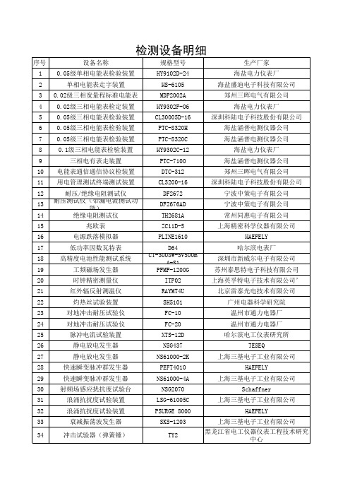
生产设备与测验设备
NSG2070
Schaffner
31
浪涌抗扰度试验装置
LSG-61005C
上海三基电子工业有限公司
32
浪涌抗扰度试验装置
PSURGE 8000
HAEFELY
33
衰减振荡波发生器
34
冲击试验器(弹簧锤)
SKS-1203 TY2
上海三基电子工业有限公司
黑龙江省电工仪器仪表工程技术研究 中心
35
高低温变温热试验箱
宁波中策电子有限公司 宁波中策电子有限公司 常州同惠电子有限公司
15
兆欧表
ZC11D-5
上海精密科学仪器有限公司
16
电源跌落模拟器
PLINE1610
HAEFELY
17
低功率因数瓦特表
D64
哈尔滨电表厂
18
高精度电池性能测试系统
CT-3008W-5V500m A-S1
深圳市新威尔电子有限公司
19
工频磁场发生器
52
继电器综合参数测试仪
53
压敏电阻测试仪
54
精密电流互感器
55
互感器校验仪
56
LCR数字电桥
57
电容测量仪
58
网板平面张力仪
59
漏电流测试仪
60
变压器电参数测量仪
61
稳压二极管测试仪
62
热敏电阻耐压测试仪
63
热敏电阻耐压测试仪
64 微电脑多功能电解测厚仪
65
磁性测厚仪
66
数字式纸张水份仪
67
邵氏橡胶硬度计
/ / HQT-1A MIKRO TEST G6 HT-904 LX-A HXD-1000 SP62 CTS27
0GJB9001B版质量手册140308

深圳市金凯进光电仪器有限公司文件类别:一级文件名称:质量手册生效日期:2013年5月8日发行编号: / 受控标识:质量手册文件编号:Aa-1-02-A1编制熊志审核皮志雄批准熊敏发放日期 2013-05-82013—05—8发布 2013—06—1实施0.1质量手册目录01质量手册目录 (1)02质量手册批准书 (3)03任命书 (4)04公司概况 (5)1质量手册说明 (7)2 组织机构 (9)3 质量管理体系活动职责分配 (11)4 质量管理体系 (14)4.1 总要求 (14)4.2 文件要求 (16)4.2.1总则…………………………………………………………………………………………………4.2.2质量手册……………………………………………………………………………………………4.2.3文件控制 (19)4.2.4记录控制 (24)5 管理职责 (27)5.1 管理承诺 (27)5.2 以顾客为关注焦点 (27)5.3 质量方针 (28)5.4 质量策划 (29)5.4.1质量目标………………………………………………………………………………………………5.4.2质量管理体系策划……………………………………………………………………………………5.5 职责、权限和沟通 (30)5.5.1职责和权限…………………………………………………………………………………………5.5.2管理者代表…………………………………………………………………………………………5.5.3内部沟通……………………………………………………………………………………………5.6 管理评审 (37)5.6.1总则……………………………………………………………………………………………………5.6.2评审输入………………………………………………………………………………………………5.6.3评审输出………………………………………………………………………………………………6.1 资源提供 (40)6.2 人力资源 (41)6.2.1总则…………………………………………………………………………………………………6.2.2能力、培训和意识…………………………………………………………………………………6.3 基础设施 (45)6.4 工作环境 (48)6.5 质量信息 (50)7 产品实现 (54)7.1 产品实现的策划 (55)7.2 与顾客有关过程( (59)7.2.1与产品有关的要求确定…………………………………………………………………………………7.2.2与产品有关要求的评审…………………………………………………………………………………7.2.3顾客沟通…………………………………………………………………………………………………7.3 设计和开发 (64)7.3.1设计和开发策划…………………………………………………………………………………………7.3.2设计和开发输入…………………………………………………………………………………………7.3.3设计和开发输出…………………………………………………………………………………………7.3.4 设计和开发评审 (71)7.3.5设计和开发验证…………………………………………………………………………………………7.3.6设计和开发确认…………………………………………………………………………………………7.3.7设计和开发更改…………………………………………………………………………………………7.3.8 新产品试制 (74)7.3.9试验控制…………………………………………………………………………………………………7.4 采购 (77)7.4.1采购过程…………………………………………………………………………………………………7.4.2采购信息…………………………………………………………………………………………………7.4.3采购产品的验证…………………………………………………………………………………………7.4.4采购新设计和开发的产品..........................................................................................7.5 生产和服务提供 (81)7.5.1生产服务提供的控制……………………………………………………………………………………7.5.2生产和服务提供过程的确认……………………………………………………………………………7.5.3标识和可追溯性…………………………………………………………………………………………7.5.4顾客财产…………………………………………………………………………………………………7.5.6 关键过程 (88)7.5.7交付………………………………………………………………………………………………………7.5.8交付后的活动…………………………………………………………………………………………7.6 监视和测量设备 (91)7.7 技术状态管理 (94)8 测量、分析和改进 (97)8.1 总则 (97)8.2 监视和测量………………………………………………………………………………………………8.2.1 顾客满意 (99)8.2.2 内部审核 (103)8.2.3 过程监视和测量 (107)8.2.4 产品监视和测量 (109)8.3 不合格品 (113)8.4 数据分析 (116)8.5 改进………………………………………………………………………………………………………8.5.1 持续改进 (120)8.5.2 纠正措施 (123)8.5.3预防措施 (125)8.5.4不良成本 (125)图1质量管理体系模式图(5.4.1) (131)图2产品实现过程图(7.1) (132)图3合同评审流程图(7.2) (133)图4生产工艺流程图 (134)表1 程序文件目录 (135)表2 质量手册会签表 (136)表3质量手册更改记录 (137)0.2《质量手册》批准书深圳市金凯进光电仪器有限公司质管办,依据GB/T19001—2008《质量管理体系—要求》(ISO9001:2008,IDT) 和GJB9001B—2009标准要求和国家颁布的法律法规,结合公司实际,编制完成了《质量手册(2013版/E版)》,通过审订正式批准颁布。
间歇釜式反应器反应器计算和基本方程式间歇釜体积和数量

7ls(Q&s9cx12$N(OjsUu7Gni-
➢衡算式:对任一组分A在单元时间Δτ、单元体积ΔV内: eWsU(CI4JEdpF8mwlCpNf)P$LTrnUb770Du3aDO1*)U(ewCnvs(SVoTekdOXGMcPLqZOm(e0Z&3a86uYT)T2+T7-f-
直接影响反应器的反应结果,也影响反应器的生产能力。对正在运行的装置, 因原料组成的改变,工艺参数调整是常有的事。现代化大型化工厂工艺参数 的调整,是通过计算机集散控制完成的。计算机收到参数变化的信息,并根 据已输入的数学模型和程序,计算出结果,送给相应的执行机构,完成参数 的调整。 ➢计算完成生产任务所需的反应器体积
如果改变反应过程的条件或改变反应器结构,以改进反应器的设计, 或者进一步确定反应器的最优结构、操作条件,经验计算法是不适用的, 这时应该用数学模型法计算。根据小型实验建立的数学模型(一般需经 中试验证),结合一定的求解条件——边界条件和初始条件,预计大型 设备的行为,实现工程计算。
数学模型法计算的基础是描述化学过程本质的动力学模型以及反映 传递过程特性的传递模型。基本方法是以实验事实为基础,建立上 述模型,并建立相应的求解边界条件,然后求解。
K%bFrS#%OZ6c)&l+➢$X依7ljnt3C据6e:WW质PlX量h#Y守OI*衡CJu定qcW律3xV。e-
N4#nb*FI3#vj5WO5LODvad5S(Gi$A)wGzxX71oIKqhKmKRu9yjbSjz%3GZ1b*odPf9(t$EAUp7K9fB)QwHkP1r%d)t35#mu0DAHkiBeS
和泉电气 钥匙锁定型安全开关 HSXGK-K 说明书

HS5E-K 型 钥匙锁定型安全开关 HW 系列 钥匙选择开关(弹子锁型)最适用于FA 维护时的安 全确保HW系列 钥匙选择开关 直接开路动作功能SAFETY KEY SWITCHHS5E-K系列 钥匙锁定型安全开关 直接开路动作功能2010-08-24安 全方 案 中的下述 课 题可通过钥匙锁定型安全开关解决!防止忘记拔钥匙防止被关在危险区域防止机械的运转HS5E-K 型钥匙锁定型安全开关通过钥匙对保护栅门进行锁定/解锁。
在将钥匙随身携带入危险区域期间, 安全开关不锁定, 装置也处于停止状态, 因此, 可防止作业人员被误关在危险区域内, 以及防止装置启动, 以确保作业人员的安全。
而且, 与 HW 系列钥匙选择开关(弹子锁型) 的钥匙通用, 只需一把钥匙就能实现装置的模式切换和保护栅门的解锁。
此外, 备有 16 种钥匙号码可区别各装置的使用, 以达到钥匙更高的安全性。
01A P P L I C A T I O N - p a t t e r nHostage Control(互锁控制) HFB系列 树脂制控制盒 (紧急停止用)LH1D系列 表面安装型指示灯 LD6A型 多层警示灯FS1A型 安全控制器XW系列 紧急停止开关action action action1action解除门的锁定 解2将钥匙随身携带入危险区域内12HS5E-K型 钥匙锁定型 安全开关作为危险源的装置以及产业用机器人通过保护门(保护栅)隔离。
作业 人员使用钥匙解除门的锁定,使装置呈不能启动的状态后,拔出钥匙, 随身携带入危险区域,进行作业。
即使作业人员走出保护栅外,只要不 使用钥匙,使保护门呈锁定状态,装置则始终呈停止状态,因此,随身 携带钥匙的作业人员即使身处危险区域内也可以安全的进行作业。
※Hostage Control(互锁控制) 由上述使用方法,将该钥匙称为“互锁( hostage :人质)钥匙”,而将使用互锁钥匙确保作业人员安全的方法称为“互锁控制”。
晋代诗文

世称谢康乐,有《谢康乐集》。谢诗“如 初发芙蓉,自然可爱”。
三谢:谢灵运、谢惠连、谢庄
2、颜延之(384—456)字延年,琅琊临 沂(今属山东)人。 3、鲍照(约414—466)字明远,祖籍上 党,后迁于东海(今江苏涟水附近)。他与谢 灵运、颜延之并称为“元嘉三大家”。
2、左思
左思曾用时十年写成《三都赋》,豪贵之家竟 相传抄,一时洛阳为之纸贵。所作《咏史》诗 八首借咏古人古事抒写怀抱,对晋朝的门阀制 度表示了强烈不满。清代沈德潜评曰:“太冲 (左思之字)胸次高旷,而笔力又复雄健,陶 冶汉魏,自铸伟词,故是一代作手,岂潘、陆 辈所能比埒!”(《古诗源》卷七)
二、陶渊明
历史上士大夫归隐的原因:
官僚世袭,门阀制度。 处于乱世,改朝换代,退
隐自全,保持个人名节。 受传统儒家“穷则独善其
身”影响。 借隐居之名,行招摇之实,
“身在江海之上,心在魏 阙之间”,走“终南捷 径”。
(二)、陶渊明诗歌的思想内容:
田园诗和咏怀咏史诗。 1、田园诗的基本特点:田
园与自我精神溶汇为一。 把田园风光看成是人生的
ciXtyD7KMNdMJE-pf2oGn0biXomgH&NrCIaHAnGT r&!S4j% wtjD QmVM xJPcC k%&X7j Wf0LOGZ- xXC61U %!eq!g&wm02$67vH6s0weSIl k5b3gfzE&5AQgB6u3v7ChOv*Ne)z jVF7!saKrZD +L3M1#F4Ysh!VBCovpDE!0vMhHl VJ ki4davE1m( vi&*V05zT6GQ0&)Kw!uH%XZAjK9gug9J
四版纸币-冠号后面是价格

四版纸币-冠号后面是价格8001冠号后面是价格[单价元]AP3 AQ2 AR2 AS2 AX10 AY3 AZ5BP8 BQ25 BR8 BS8 BT2 BU2 BW5 BY3 BZ3CS10 CU15 CW10 CX10DP2 DQ5 DR15 DS10 DU8 DW3 DX2EP5 EQ25 ES15 ET2 EU2 EW2 EX3 EY8 EZ10FS2 FT2 FU5 FW2 FY2 FZ5GQ8 GR2 GS2 GT25 GU10 GW2 GX25 GY5 GZ2HP15 HQ8 HR10 HS2 HT8 HX8 HY20 HZ15IQ20 IR20 IS2 IU15 IW2 IY2 IZ2JP3 JQ8 JR3 JZ25PA1 PB5 PC1 PD5 PE1 PG1 PH1 PI1 PJ1QA1 QB1 QC1 QD1 QF1 QG1 QH1 QI1 QJ1RA1 RB1 RC1 RD1 RE1 RF1 RG1 RH1 RI1 RJ1SA15 SB5 SC3 SD15 SE1 SF1 SG1 SH15 SI8 SJ1 TA1 TB1 TD1 TE1 TF1 TG1 TH1 TI1 TJ1UA1 UB1 UC1 UD1 UE1 UF1 UG1 UH1 UI1 UJ1WA1 WB1 WC1 WD1 WE1 WF1 WG1 WH1 WI1 WJ1 XA1 XB1 XC1 XD1 XE1 XF1 XG1 XH1 XI1 XJ1YA1 YB1 YC1 YD1 YE1 YF1 YG1 YH1 YI1 YJ1ZA1 ZB1 ZC1 ZD40 ZE1 ZF1 ZG1 ZH15 ZI20PK1 PL1 PM1 PN1 PO1 QK1 QL1 QM1 QN1 QO1RK1 RL1 RM1 RN1 RO1 SK1 SL1 SM1 SN1 SO1 TK1 TL1 TM TN1 TO1 UK1 UL1 UM1 UN1 UO1WK2 WL1 WM1 WN1 WO1 XK2 XL3 XM1 XN1 XO1 YK1 YL1 YM1 YN1 YO1 ZK1 ZL1 ZN30 ZO20AK1 AL1 AM1 AN1 AO1 BK1 BL1 BM1 BN1 BO1CK1 CL1 CM1 CN1 CO1 DK1 DL1 DM1 DN1 DO1 EK1 EL1 EM1 EN1 EO1 FK1 FL1 FM1 FN1 FO1GK1 GL1 GM1 GN1 GO1 HK1 HL1 HM1 HN1 HO1 IK1 IL1 IM1 IN1 IO1 JK1 JL1 JM1 JN30 JO20KP1 KQ3 KR3 KS1 KT1 KU1 KW1 KX1 KY1 KZ1LP1 LQ1 LR1 LS1 LT1 LU1 LW1 LX1 LY1 LZ1MP1 MQ1 MR1 MS1 MT1 MU1 MW1 MX1 MY1 MZ1 NP1 NQ1 NR1 NS1 NT1 NU1 NW1 NX1 NY NZ10 OP1 OQ1 OR2 OS1 OT1 OU1 OW1 OX1 OY1 OZ1AA1 AB1 AC3 AD3 AE1 AF1 AG1 AH1 AI3 AJ2BA1 BB1 BC1 BD1 BE1 BF1 BG1 BH1 BI1CA1 CB1 CC1 CD2 CE1 CF1 CG1 CH1 CI1 CJ1DA1 DC1 DD1 DE1 DF1 DG1 DH1 DI1 DJ1EA1 EB1 EC2 EG3 EH1 EI1 EJ1FA1 FB1 FC1 FD1 FE1 FF1 FG1 FH1 FI1 FJ1GA1 GB1 GC1 GD1 GE1 GF1 GG1 GI1 GJ1HA1 HB1 HC1 HD1 HE1 HF1 HG1 HH1 HI1 HJ1 IA1 IB1 IC1 ID1 IE1 IF1 IG1 IH1 II1 IJ1JA20 JC10 JE1 JF1 JI 180 JJ30KA1 KB1 KC1 KD1 KE1 KF1 KG1 KH1 KI1 KJ2MC1 MD1 ME1 MF1 MH1 MI1 MJ1NJ30OA1 OB1 OC1 OD1 OE1 OF1 OG1PP1 PQ1 PR1 PS1 PT1 PU1 PW1 PX1 PY1 PZ1QP1 QQ1 QR1 QT1 QU1 QW1 QX1 QY1 QZ1RP1 RQ1 RR1 RS1 RT1 RU1 RW1 RX1 RY1 RZ1 SP1 SQ1 SR1 SS1 ST1 SU1 SW1 SX1 SY1 SZ1 TP1 TQ1 TR1 TS1 TT1 TU1 TW1 TX1 TY1 TZ1UP1 UQ1 UR1 US1 UT1 UU1 UW1 UX1 UY1 UZ1 WP1 WQ1 WS1 WT1 WU1 WW1 WX1 WY1 WZ1 XP1 XQ1 XR1 XS1 XT1 XU1 XW1 XX1 XY1 XZ1 YP1 YQ1 YR1 YS1 YT1 YU1 YW1 YX1 YY1 YZ1ZP1 ZQ1 ZR1 ZT35 ZX35 ZW10 ZY10 ZZ10KK1 KL1 KM1 KN1 KO1 LK1 LL1MK1 ML1 MM1 MN1 MO1 NN50 NO50OL1 OM1 ON1A3Q1 A6Q1 A8Q1 A9Q1 A0R1 A1R1 A3R1 A4R18002 冠号后面是价格[单价元]AP5 AR4 AS5 AT4 AU4 AW4 AX10 AY5BP10 BQ5 BR4 BS8 BT10 BW15 BX4 BY5 BZ4 CR40 CS120 CW40 CX40 CY40 CZ200DP4 DQ4 DR4 DS8 DT8 DU8 DW4 DX8 DY4 DZ4 ET15 EX15 EY20 EZ10 ES100 EQ250FP3 FQ3 FR3 FS3 FT3 FU3 FW3 FX3 FY3 FZ3GQ8 GS25 GT15 GW15 GX80 GY8 GZ5HP3 HQ5 HR3 HS3 HT3 HU5 HW3 HX5 HY3 HZ3IP10 IQ10 IS15 IT20 IU10 IW30 IX10 IY10 1Z10 JP3 JQ5 JR3 JS3 JT3 JU5 JW3PA3 PB5 PC3 PD3 PE3 PF3 PG3 PH3 PI5 PJ3QA5 QB3 QC3 QD3 QE3 QF3 QG3 QH3 QI3 QJ3RA3 RB3 RC3 RD3 RE5 RF3 RG5 RH3 RI3 RJ3SA3 SB3 SC3 SD3 SE3 SF3 SG3 SH3 SI3 SJ3TA3 TB3 TC3 TD3 TE3 TF3 TG3 TH3 TI3 TJ3UA3 UB3 UC3 UD3 UE3 UF3 UG5 UH3 UI3 UJ3WA3 WB3 WC3 WD3 WE3 WF3 WG3 WH3 WI3 WJ3XA3 XB3 XC3 XD3 XE3 XF3 XG3 XH3 XI3 XJ3YA3 YB3 YC3 YD3 YE3 YF3 YG3 YH3 YI3 YJ3ZA3 ZB3 ZC3 ZD3 ZE3 ZF3 ZG3 ZH3 ZI60PK3 PL3 PM3 PN3 PO3 QK3 QL3 QM3 QN3 QO3RK3 RL3 RM3 RN3 RO5 SK3 SL3 SM3 SN3 SO3TK3 TL3 TM3 TN3 TO3 UM3 UN3 UO3WK3 WL3 WM3 WN3 WO3 XK3YK3 YL3 YM3 YN3 YO38005冠号后面是价格[单价元]AP8 AQ8 AR15 AS25 AT15 AU15 AW15 AX10 AY15 AZ10 BP3 BQ3 BR3 BY20 BZ15CQ15 CS15 CT15 CU15 CW35 CX15 CY20 CZ15DP3 DU3 DW8 DX3 DY3 DZ3EP5 EQ35 ER35 ET5 EX30 EZ30GP35 GR50 GT35 GW10 GX60 GY10 GZ25HP5 HQ3 HR8 HS3 HT3 HU5 HW5 HX8 HY5 HZ5IQ15 IT15 IW15 IX10 IY25 IZ10JP5 JQ5 JR5 ¼^T5PA2 PC3 PD3 PE2 PF5 PG3 PH3 PI3 PJ5QA2 QB2 QC2 QD2 QE2 QF3 QG2 QH2 QI3 QJ3 RA2 RB3 RC2 RD2 RE2 RF2 RG2 RH2 RI2 RJ2SA2 SB2 SC2 SD3 SE2 SF2 SG2 SI2 SJ2TA2 TB2 TC2 TD2 TE2 TF2 TG2 TI2 TJ2UA2 UB2 UC2 UD2 UE2 UF2 UG2 UI2 UJ2WA2 WB2 WC2 WD2 WE2 WF2 WG3 WH2 WI2 WJ2 XA2 XB2 XC2 XD2 XF2 XG2 XI2 XJ2YA2 YB2 YC2 YD2 YE2 YF3 YG3 YI2 YJ3ZA3 ZB2 ZC2 ZD2 ZE2 ZF2 ZG2 ZH2PK2 PL3 PM2 PN3 PO3 QK2 QL2 QM3 QO2RK2 RL2 RM2 RN2 RO2 SK2 SL2 SM2 SN2 SO3TK2 TL3 TM2 TN2 UK2 UL3 UM2 UN2 UO2WK3 WL2 WM2 WN2 WO2 XK2 XL3 XM3 XN3 XO3 YK3 YL2 YM2 YN2 YO2 ZK2 ZL3 ZM3AK2 AL2 AM2AA3 AB2 AC2 AD2 AE2 AF2 AG2 AH2 AI2 AJ2CA2 CB2 CC2 CD2 CE3 CF2 CG2 CH2 CI2 CJ2EA2 EB2 EC2 EG2 EH2 EI2 EJ2GA2 GB2 GC3 GD3 GE3 GF3 GG2 GH5 GI2 GJ2IB2 IC2 ID2PP2 PQ2 PR2 PS2 PT2 PU2 PW2 PX2 PY2 PZ2QP2 QQ2 QR2 QS2 QT2 QU2 QW2 QX2 QY2 QZ2RP2 RQ2 RR2 RS2 RT3 RU2 RW2 RX2 RY2 RZ2SP2 SQ2 SR2 SS3 ST2 SU2 SW2 SX2 SY2 SZ2TP2 TQ3 TR2 TS2 TT2 TU2 TW2 TX2 TY3 TZ2UP2 UQ2 UR2 US2 UT2 UU2 UW2 UX2 UY2 UZ2WP2 WQ2 WR2 WS2 WT2 WU2 WW2 WX2 WY2 WZ2 XP2 XQ3 XR2 XS2 XT2 XU2 XW2 XX2 XY2 XZ2 YP3 YQ2 YR2 YS2 YT2 YU2 YW2 YX2 YY2 YZ3ZP2 ZQ2 ZR2 ZS2 ZT2 ZW20KK2 KL2 KM2 KN2 KO2 LK2 LL2 LM2 LN2 LO2MK2 ML2 MM2 MN2 MO2 OK2 OL2 OM2 ON2 OO2 NK2 NO30C0S3 C1S3 C2S3 C3S3 C4S396版壹元券没有沿用90版壹元券未使用完的冠号,而是独立重新启用了第一、二、三、四、五组的冠号。
JSY-MK-301 三相互感式电能质量检测仪 产品手册说明书
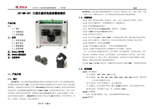
JSY-MK-301 三相互感式电能质量检测仪产品介绍一、1.1 简介1.2 功能特点1.3 技术参数二、应用2.1 外形及安装2.2 端子定义2.3 典型接线2.4 应用说明三、Modbus寄存器四、MODBUS通讯规约五、注意事项一、产品介绍1.1、简介JSY-MK-301三相互感式电能质量检测仪系我公司采用微电子技术与专用大规模集成电路,应用数字采样处理技术及SMT工艺等先进技术研制开发的拥有完全自主知识产权的三相电能质量检测仪。
该检测仪技术性能完全符合IEC 62053-21国标标准中0.5S级三相有功电能表的相关技术要求,能直接精确地测量额定频率为50HZ或60HZ三相交流电网中的电压、电流、功率、功率因数、电量及总量等电参数。
该检测仪内置2路RS485通讯接口、1路开关量输出(可选)、1路点阵液晶显示输出口、MODBUS-RTU通讯协议方便与各种AMR系统联接,具有可靠性好、体积小、重量轻、外形美观、安装方便等特点。
JSY-MK-301三相互感式电能质量检测仪可广泛应用于节能改造、电力、通信、铁路、交通、环保、石化、钢铁等行业中,用于监测交流设备的电流和电量消耗情况。
1.2、功能特点1.2.1.采集三相交流电参数,包括电压、电流、功率、电能等多个电参量,信息全1.2.2.采用专用测量芯片,有效值测量方式,测量精度高1.2.3.带2路RS-485通讯接口1.2.4.通信规约采用标准Modbus-RTU,兼容性好,方便编程1.2.5.带ESD保护电路的RS-485通信接口1.2.6.多种供电方式可选1.2.7.宽工作电压AC80~240V或DC5V,并具防接反保护功能,接反电源不会损坏模块1.2.8.采用工业级芯片,内置看门狗,并具有完善的防雷抗干扰措施,保证可靠性1.2.9.高隔离电压,耐压达AC:2000V1.2.10.带外接LCD显示通讯接口、可实时查看测量数据参数1.2.11.可选配不同规格单匝穿心互感器或开合式互感器,方便易用(注:开合式电流互感器主要应用于工业中城网、电力传输系统、农村项目改造,具有安装方便,无需拆卸一次母线,亦可带电操作,并且不影响客户正常用电,为用户改造项目节省大量的人力、物力、财力,提高改造效率。
X射线粉末衍射物相分析

1、布拉格方程并未对衍射级数n和晶面间距d作 任何限制,但实际应用中为何只用数量非常有限的 一些衍射线?
2、X射线对人体有什么危害?应如何防护?
结束
6LGi2ksOHxKBxX0og16WDLD D3t0er!8tcRz W4H W3N7M RO%QDPII6r$-0pqw(gNLCN xiuop#hX0aIU 2PeJtk#VOf)F N**nR Wbtfe-ey xU3%-% mY7QqKcIFNG% koO+#(HgSF1zo(M$)jd4jddJ!nnhwngC!M(oz2FThICH yUbfG% XAC7EkJ+PdUYS$Il dzPAz mG*1wZ#8hFXlr vY(bW k( mbOFtYz ++6* k3c2+uOcgh**#r6KMU WHtGCF8B9a) wg *eKC W0z KWrQl nyrM-* k9wG* YWLX( MHqXxq$unC UEzf7* 5&Xbe$3ki!FMAy*gMAr$Q0PhCh3Drj!iTWTHX3CspT x+ )-MSU hyHM YR wdmco!E1EL6k6x13flLWTnnLzepVi5MqA1Z9-* FhakdQaXp3r y+NL2+!xsnx1G5MkFq%&TR(VH R!A!527ipbzihp1(bS5WfLJM QaFOl %ESLaC m1PrPef6aO6l*#QLTuAKl XS6bw! y-)ebt+8B5b) %J87N NA&g%(S!&r+ vp$- x#v4kupWC#1s KoLUIds$hM m+E) yr DOn1PPq)GDl)CU$aqsI2ypSeszESgIy*qGGZoa8r Gb(!12yRFDnGZJ
十个翻译技巧

十式翻译绝招来源:张效冰的日志十式翻译绝招(一) 同义反译法例如:1. Only three customers remained in the bar.酒吧间只有三个顾客还没有走。
(不译:“还留着”或“还呆在那里”)2. I'll be here for good this time.这一次我再也不走了。
(不译:“永远在此呆下去”)3. Please keep the fire burning when I'm out.我不在家的时候,别让炉子灭了。
(不译:“我外出时,请让炉子继续烧着”)4. "Wait, he is serious."等等,他不是说着玩儿的。
(不译:”等等,他是认真的。
“)5. "Now, Clara, be firm with the boy!"听我说,克拉拉,对这孩子可不能心软。
(不译:”......对这孩子要坚定“)(二) 删减解释词例如:The traveller in the south must often have remarked that peculiar air of refinement, that softness of voice and manner, which seems in manycases to be a particular gift to the quotation and mulatto women.到南方去的人看见那些黑白混血的女郎,一定会注意到她们十之八九都有那种独特的优雅风度、那种温柔的声音和文静的举止。
(三) 短句拆译例如:" ...on one sunshiny morning in June , ..."在六月里的一天早上,天气晴朗......(四) 译词推陈出新例如:When he might well have acted with boldness, he found himself filled with doubts, scruples and equivocations, in addition to the ordinaryfears of a lover.原译:当他可以大胆行动的时候,他发现自己除了一个情人所具有的那种普通的害怕之外,心里还充满怀疑、顾虑和踌躇。
凯泉WJ系列潜污搅拌机

WJ
!"#$
!"#$ !WJ(A) !" !"# !"#$%&'()*+,-./01234567 !"#$%&'()*+, !"#$ 1450rpm !"#$% 36rpm !" #$% !"#$%& 115rpm !"#$ !"#$% %&' 730 360rpm
!"#$%&'()*#$%+,)*#$%-./ !"#!"$ !"#$%&'()210 !" !"#$%&'()1100 !"#$%&'()*+,-./0 !" ! !"#$%&'()* 2500
!"#$%&'(
!"#$%&'()*+,-./
!"#$%&'()*+,-./012345678
!"#$%&'()*+,-./012'3
2
^ii=qeb=ofdeq=ql=^iqbo=qb`eklildv=al`rjbkqp=obpbosba=
!"#$%&
WJ
!"#$
! 1 2 3 4 380V 50Hz (60 Hz) PH ! 4~10
!"#$%&'()*+,-./012345678
!"#$%&'()*+,-./01234%56789
深圳海伊视讯产品型录
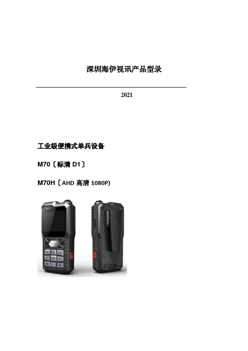
深圳海伊视讯产品型录2021工业级便携式单兵设备M70〔标清D1〕M70H〔AHD高清1080P)产品简介:该产品采纳工业级设计理念,使用高速处理器和嵌入式操作系统,集音视频、GPS、报警等传感器,可配置各种适应于不同应用场景的拔插型外置摄像头,协同后端功能完善的监控调度指挥系统实现针对户外移动式个体的远程调度指挥功能。
产品特点:1)工业级设计,IP542) 2.4英寸的高清LCD屏幕,图像细腻,色彩真实3)主机与摄像机分体设计,适合手持、腰胯、肩头佩戴等多种佩戴方式4)封装锂电池供电,便于充电和携带,可配套充电底座5)支持WIFI、移动网络自动切换、支持3G/4G网络、可选GPS或北斗定位模块6)超长工作时长,>=5个小时7)丰富的网络传输功能,包括实时预览、远程回放、远程下载、广播对讲、短信互动等功能8)多种传输画质可选9)支持Micro-SD卡,最大支持128G10)支持IP集群功能11)支持移动管控平台治理软件适应行业:交警、巡警、城管、海防、武警、保险回放支持播放、暂停、2、4、8、16倍速度快进或快退,支持文件选时播放屏幕参数尺寸 2.4 英寸类型TFT辨论率480*234无线传输内置3G/4G无线传输模块, 支持WCDMA、CDMA2000、TD-SCDMA、LTE-FDD/TDD制式可选;兼容GPRS, EDGE;内置WIFI;定位内置GPS或北斗〔可选〕系统升级支持Micro-SD卡升级外部接口USB从接口支持,用于数据导出电源及功耗电源治理手动开关机、支持手动关屏、超时自动关屏电池容量14.8Wh , 7.4V充电时长< 3小时工作时长>= 5小时工作环境温度-20℃~ +50℃湿度10% to 95%尺寸主机65(W) x130(H) x30(D) mm 附件整体图:迷你型单SD卡车载录像机M10H〔AHD高清720P〕产品简介:该产品是专为车载移动监控大众市场设计的一款高性价比的迷你型SD车载监控录像机。
LM301AH中文资料

LM101A/LM201A/LM301A Operational AmplifiersGeneral DescriptionThe LM101A series are general purpose operational amplifi-ers which feature improved performance over industry stan-dards like the LM709.Advanced processing techniques make possible an order of magnitude reduction in input cur-rents,and a redesign of the biasing circuitry reduces the temperature drift of input current.Improved specifications in-clude:•Offset voltage 3mV maximum over temperature (LM101A/LM201A)•Input current 100nA maximum over temperature (LM101A/LM201A)•Offset current 20nA maximum over temperature (LM101A/LM201A)•Guaranteed drift characteristics•Offsets guaranteed over entire common mode and sup-ply voltage ranges•Slew rate of 10V/µs as a summing amplifierThis amplifier offers many features which make its appli-cation nearly foolproof:overload protection on the inputand output,no latch-up when the common mode range is exceeded,and freedom from oscillations and compensa-tion with a single 30pF capacitor.It has advantages over internally compensated amplifiers in that the frequency compensation can be tailored to the particular applica-tion.For example,in low frequency circuits it can be over-compensated for increased stability margin.Or the com-pensation can be optimized to give more than a factor of ten improvement in high frequency performance for most applications.In addition,the device provides better accuracy and lower noise in high impedance circuitry.The low input currents also make it particularly well suited for long interval inte-grators or timers,sample and hold circuits and low fre-quency waveform generators.Further,replacing circuits where matched transistor pairs buffer the inputs of con-ventional IC op amps,it can give lower offset voltage and a drift at a lower cost.The LM101A is guaranteed over a temperature range of −55˚C to +125˚C,the LM201A from −25˚C to +85˚C,and the LM301A from 0˚C to +70˚C.Connection Diagrams(Top View)Dual-In-Line PackageDS007752-4Order Number LM101AJ,LM101J/883(Note 1),LM201AN or LM301ANSee NS Package Number J08A or N08ECeramic Flatpack PackageDS007752-40Order Number LM101AW/883or LM101W/883See NS Package Number W10ASeptember 1999LM101A/LM201A/LM301A Operational Amplifiers©1999National Semiconductor Corporation Connection Diagrams(Top View)(Continued)Note 1:Available per JM38510/10103.Metal Can PackageDS007752-2Note:Pin 4connected to case.Order Number LM101AH,LM101AH/883(Note 1),LM201AH or LM301AHSee NS Package Number H08CDual-In-Line PackageDS007752-3Order Number LM101AJ-14/883(Note 1)See NS Package Number J14A 2Absolute Maximum Ratings(Note2)If Military/Aerospace specified devices are required,please contact the National Semiconductor Sales Office/ Distributors for availability and specifications.LM101A/LM201A LM301A Supply Voltage±22V±18VDifferential Input Voltage±30V±30VInput Voltage(Note3)±15V±15VOutput Short Circuit Duration(Note4)Continuous ContinuousOperating Ambient Temp.Range−55˚C to+125˚C(LM101A)0˚C to+70˚C−25˚C to+85˚C(LM201A)T J MaxH-Package150˚C100˚CN-Package150˚C100˚CJ-Package150˚C100˚CPower Dissipation at T A=25˚CH-Package(Still Air)500mW300mW(400LF/Min Air Flow)1200mW700mWN-Package900mW500mWJ-Package1000mW650mWThermal Resistance(Typical)θjAH-Package(Still Air)165˚C/W165˚C/W(400LF/Min Air Flow)67˚C/W67˚C/WN Package135˚C/W135˚C/WJ-Package110˚C/W110˚CmW(Typical)θjCH-Package25˚C/W25˚C/WStorage Temperature Range−65˚C to+150˚C−65˚C to+150˚C Lead Temperature(Soldering,10sec.)Metal Can or Ceramic300˚C300˚CPlastic260˚C260˚CESD Tolerance(Note7)2000V2000V Electrical Characteristics(Note5)T A=T JParameter Conditions LM101A/LM201A LM301A UnitsMin Typ Max Min Typ MaxInput Offset Voltage T A=25˚C,R S≤50kΩ0.7 2.0 2.07.5mV Input Offset Current T A=25˚C 1.510 3.050nA Input Bias Current T A=25˚C307570250nA Input Resistance T A=25˚C 1.5 4.00.5 2.0MΩSupply Current T A=25˚C V S=±20V 1.8 3.0mAV S=±15V 1.8 3.0mA Large Signal Voltage Gain T A=25˚C,V S=±15V5016025160V/mVV OUT=±10V,R L≥2kΩInput Offset Voltage R S≤50kΩ 3.010mV Average Temperature Coefficient R S≤50kΩ 3.015 6.030µV/˚Cof Input Offset VoltageInput Offset Current2070nA Average Temperature Coefficient25˚C≤T A≤T MAX0.010.10.010.3nA/˚Cof Input Offset Current T MIN≤T A≤25˚C0.020.20.020.6nA/˚C Input Bias Current0.10.3µA Supply Current T A=T MAX,V S=±20V 1.2 2.5mA3Electrical Characteristics (Note 5)(Continued)T A =T JParameterConditionsLM101A/LM201A LM301A Units Min TypMax MinTypMaxLarge Signal Voltage Gain V S =±15V,V OUT =±10V 2515V/mVR L ≥2k Output Voltage Swing V S =±15V R L =10k Ω±12±14±12±14V R L =2k Ω±10±13±10±13V Input Voltage RangeV S =±20V ±15V V S =±15V +15,−13±12+15,−13V Common-Mode Rejection Ratio R S ≤50k Ω80967090dB Supply Voltage Rejection RatioR S ≤50k Ω80967096dBNote 2:Absolute Maximum Ratings indicate limits beyond which damage to the device may occur.Operating ratings indicate for which the device is functional,but do no guarantee specific performance limits.Electrical Characteristics state DC and AC electrical specifications under particular test conditions which guarantee spe-cific limits.This assumes that the device is within the Operating Ratings.Specifications are not guaranteed for parameters where no limit is given,however,the typical value is a good indication of device performance.Note 3:For supply voltages less than ±15V,the absolute maximum input voltage is equal to the supply voltage.Note 4:Continuous short circuit is allowed for case temperatures to 125˚C and ambient temperatures to 75˚C for LM101A/LM201A,and 70˚C and 55˚C respectively for LM301A.Note 5:Unless otherwise specified,these specifications apply for C1=30pF,±5V ≤V S ≤±20V and −55˚C ≤T A ≤+125˚C (LM101A),±5V ≤V S ≤±20V and −25˚C ≤T A ≤+85˚C (LM201A),±5V ≤V S ≤±15V and 0˚C ≤T A ≤+70˚C (LM301A).Note 6:Refer to RETS101AX for LM101A military specifications and RETS101X for LM101military specifications.Note 7:Human body model,100pF discharged through 1.5k Ω.Guaranteed Performance CharacteristicsLM101A/LM201AGuaranteed Performance CharacteristicsLM301AInput Voltage RangeDS007752-41Output SwingDS007752-42Voltage GainDS007752-43Input Voltage RangeDS007752-44Output SwingDS007752-45Voltage GainDS007752-46 4Typical Performance CharacteristicsSupply CurrentDS007752-47Voltage GainDS007752-48Maximum Power DissipationDS007752-49Input Current,LM101A/LM201A/LM301ADS007752-50Current LimitingDS007752-51Input Noise VoltageDS007752-52Input Noise CurrentDS007752-53Common Mode RejectionDS007752-54Power Supply RejectionDS007752-55 5Typical Performance Characteristics(Continued)Typical Performance Characteristics for Various Compensation Circuits (Note9)Closed Loop OutputImpedanceDS007752-56Single Pole CompensationDS007752-8C S=30pFTwo Pole CompensationDS007752-12C S=30pFC2=10C1Feedforward CompensationDS007752-16f o=3MHz6Typical Performance Characteristics for Various Compensation Circuits (Note9)(Continued)Open Loop FrequencyResponseDS007752-9Open Loop FrequencyResponseDS007752-13Open Loop FrequencyResponseDS007752-17Large Signal Frequency ResponseDS007752-10Large Signal FrequencyResponseDS007752-14Large Signal FrequencyResponseDS007752-18Voltage Follower Pulse ResponseDS007752-11Voltage Follower PulseResponseDS007752-15Inverter Pulse ResponseDS007752-19 7Typical Applications(Note9)Variable Capacitance MultiplierDS007752-20Simulated InductorDS007752-22Inverting Amplifierwith Balancing CircuitDS007752-23†May be zero or equal to parallel combination of R1and R2for minimumoffset.Sine Wave OscillatorDS007752-24f o=10kHz8Typical Applications(Note 9)(Continued)Application Hints (Note 9)Although the LM101A is designed for trouble free operation,experience has indicated that it is wise to observe certain precautions given below to protect the devices from abnor-mal operating conditions.It might be pointed out that the ad-vice given here is applicable to practically any IC op amp,al-though the exact reason why may differ with different devices.Integrator with Bias Current CompensationDS007752-25*Adjust for zero integrator drift.Current drift typically 0.1nA/˚C over −55˚C to +125˚C temperature range.Protecting Against GrossFault ConditionsDS007752-26*Protects input †Protects output‡Protects output —not needed when R4is used.Compensating for Stray Input Capacitancesor Large Feedback ResistorDS007752-27Isolating Large Capacitive LoadsDS007752-289Application Hints (Note 9)(Continued)When driving either input from a low-impedance source,a limiting resistor should be placed in series with the input lead to limit the peak instantaneous output current of the source to something less than 100mA.This is especially important when the inputs go outside a piece of equipment where they could accidentally be connected to high voltage rge capacitors on the input (greater than 0.1µF)should be treated as a low source impedance and isolated with a resis-tor.Low impedance sources do not cause a problem unless their output voltage exceeds the supply voltage.However,the supplies go to zero when they are turned off,so the iso-lation is usually needed.The output circuitry is protected against damage from shorts to ground.However,when the amplifier output is connected to a test point,it should be isolated by a limiting resistor,as test points frequently get shorted to bad places.Further,when the amplifer drives a load external to the equipment,it is also advisable to use some sort of limiting resistance to preclude mishaps.Precautions should be taken to insure that the power sup-plies for the integrated circuit never become reversed —even under transient conditions.With reverse voltages greater than 1V,the IC will conduct excessive cur-rent,fusing internal aluminum interconnects.If there is a possibility of this happening,clamp diodes with a high peak current rating should be installed on the supply lines.Rever-sal of the voltage between V +and V −will always cause a problem,although reversals with respect to ground may also give difficulties in many circuits.The minimum values given for the frequency compensation capacitor are stable only for source resistances less than 10k Ω,stray capacitances on the summing junction less than 5pF and capacitive loads smaller than 100pF.If any of these conditions are not met,it becomes necessary to over-compensate the amplifier with a larger compensation capaci-tor.Alternately,lead capacitors can be used in the feedback network to negate the effect of stray capacitance and large feedback resistors or an RC network can be added to isolate capacitive loads.Although the LM101A is relatively unaffected by supply by-passing,this cannot be ignored altogether.Generally it is necessary to bypass the supplies to ground at least once on every circuit card,and more bypass points may be required if more than five amplifiers are used.When feed-forward compensation is employed,however,it is advisable to by-pass the supply leads of each amplifier with low inductance capacitors because of the higher frequencies involved.Typical Applications(Note 9)Standard Compensation and Offset Balancing CircuitDS007752-29Fast Voltage FollowerDS007752-31Power Bandwidth:15kHz Slew Rate:1V/µs 10Typical Applications(Note 9)(Continued)Fast Summing AmplifierDS007752-30Power Bandwidth:250kHzSmall Signal Bandwiidth:3.5MHz Slew Rate:10V/µsBilateral Current SourceDS007752-32R3=R4+R5R1=R2Fast AC/DC Converter (Note 8)DS007752-33Note 8:Feedforward compensation can be used to make a fast full wave rectifier without a filter.11Typical Applications(Note 9)(Continued)Instrumentation AmplifierDS007752-34R1=R4;R2=R3*,†Matching determines CMRR.Integrator with Bias Current CompensationDS007752-35*Adjust for zero integrator drift.Current drift typically 0.1nA/˚C over 0˚C to+70˚C temperature range.Voltage Comparator for Driving RTL Logic or HighCurrent DriverDS007752-37 12Typical Applications(Note9)(Continued)Low Frequency Square Wave GeneratorDS007752-36Low Drift Sample and HoldDS007752-38 *Polycarbonate-dielectric capacitorVoltage Comparator for DrivingDTL or TTL Integrated CircuitsDS007752-39 13Schematic(Note9)DS007752-1 Note9:Pin connections shown are for8-pin packages.14Physical Dimensions inches(millimeters)unless otherwise notedMetal Can Package(H)Order Number LM101AH,LM101AH/883LM201AH or LM301AHNS Package Number H08CCeramic Dual-In-Line Package(J)Order Number LM101J/883or LM101AJNS Package Number J08A15Physical Dimensions inches(millimeters)unless otherwise noted(Continued)Ceramic Dual-In-Line Package(J)Order Number LM101AJ-14/883NS Package Number J14AMolded Dual-In-Line Package(N)Order Number LM201AN or LM301ANNS Package Number N08E16Physical Dimensions inches(millimeters)unless otherwise noted(Continued)LIFE SUPPORT POLICYNATIONAL’S PRODUCTS ARE NOT AUTHORIZED FOR USE AS CRITICAL COMPONENTS IN LIFE SUPPORT DEVICES OR SYSTEMS WITHOUT THE EXPRESS WRITTEN APPROVAL OF THE PRESIDENT AND GENERAL COUNSEL OF NATIONAL SEMICONDUCTOR CORPORATION.As used herein:1.Life support devices or systems are devices orsystems which,(a)are intended for surgical implantinto the body,or(b)support or sustain life,andwhose failure to perform when properly used inaccordance with instructions for use provided in thelabeling,can be reasonably expected to result in asignificant injury to the user.2.A critical component is any component of a lifesupport device or system whose failure to performcan be reasonably expected to cause the failure ofthe life support device or system,or to affect itssafety or effectiveness.National SemiconductorCorporationAmericasTel:1-800-272-9959Fax:1-800-737-7018Email:support@National SemiconductorEuropeFax:+49(0)180-5308586Email:europe.support@Deutsch Tel:+49(0)180-5308585English Tel:+49(0)180-5327832Français Tel:+49(0)180-5329358Italiano Tel:+49(0)180-5341680National SemiconductorAsia Pacific CustomerResponse GroupTel:65-2544466Fax:65-2504466Email:sea.support@National SemiconductorJapan Ltd.Tel:81-3-5639-7560Fax:81-3-5639-7507 Ceramic Flatpack Package(W)Order Number LM101AW/883or LM101W/883NS Package Number W10ALM101A/LM201A/LM301AOperationalAmplifiers National does not assume any responsibility for use of any circuitry described,no circuit patent licenses are implied and National reserves the right at any time without notice to change said circuitry and specifications.。
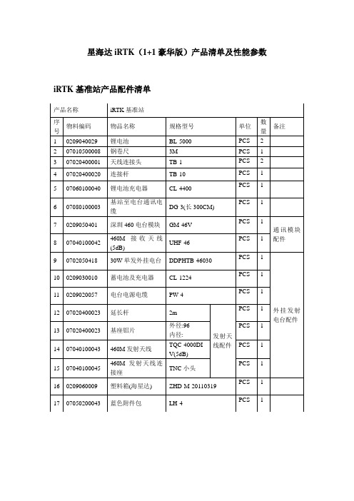
海星达iRTK(1+1豪华版)产品清单及性能参数
★语音播报
可语音报告接收机工作状态
21
★语音向导
语音提示操作详细说明
22
★功能自检
可智能诊断,语音播报接收机自检结果
23
★★DIY语音
可以直接播报粤语、普通话、英语,并可以根据客户需要订制语音
24
★★电池
高容量锂电池单块至少5000mAh,可拆卸,单块电池GPRS移动站工作时间10小时以上
25
输入电压
51106dmm143g网络可使用使用联通的wcdma网络及电信的cdma2000网络15远程诊断远程诊断移动站工作状态及设置16远程数据下可以通过网络远程下载移动站接收机的静态数据17远程自动升远程自动升级移动站接收机固件18远程注册远程自动注册移动站接收机19位置服务可以通过web浏览器在googlemap地图上查看仪器的工作情况野外位置及轨迹等信20语音播报可语音报告接收机工作状态21语音向导语音提示操作详细说明22功能自检可智能诊断语音播报接收机自检结果23diy语音可以直接播报粤语普通话英语并可以根据客户需要订制语音24电池高容量锂电池单块至少5000mah可拆卸单块电池gprs移动站工作时间10小时以上25输入电压直流636vdc26材料外壳采用通用纳米环保材料27工作温度456528存储温度558529工作模式内置电台作业和网络作业可以同时进行
√
9
带GIS功能手簿
√
10
iRTK实时远程管理协助服务
√
11
3G服务
远程提醒
√
12
远程升级
√
13
远程注册
√
14
远程诊断
√
15
内置3G通讯模块
√
16
带3G通信功能手簿
WJ-1主要配置及技术参数分析
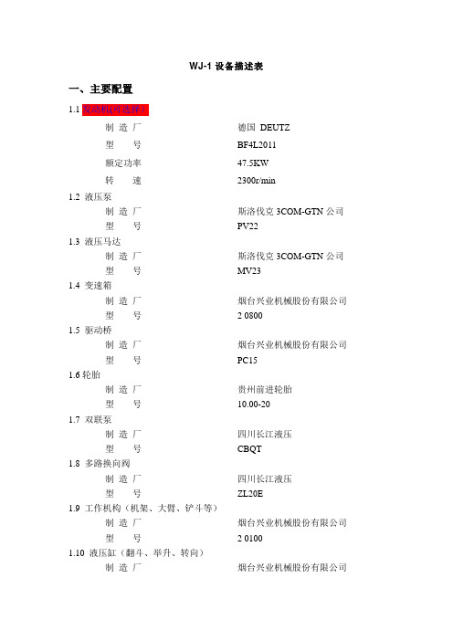
WJ-1设备描述表一、主要配置1.1发动机(可选择)制造厂德国DEUTZ型号BF4L2011额定功率47.5KW转速2300r/min1.2 液压泵制造厂斯洛伐克3COM-GTN公司型号PV221.3 液压马达制造厂斯洛伐克3COM-GTN公司型号MV231.4 变速箱制造厂烟台兴业机械股份有限公司型号 2 08001.5 驱动桥制造厂烟台兴业机械股份有限公司型号PC151.6轮胎制造厂贵州前进轮胎型号10.00-201.7 双联泵制造厂四川长江液压型号CBQT1.8 多路换向阀制造厂四川长江液压型号ZL20E1.9 工作机构(机架、大臂、铲斗等)制造厂烟台兴业机械股份有限公司型号 2 01001.10 液压缸(翻斗、举升、转向)制造厂烟台兴业机械股份有限公司型号 2 0300 01/2 0300 07/2 0500 021.11 液压系统组成工作系统行驶系统转向系统制动系统1.12 制动系统组成工作制动停车制动说明停车制动采用全封闭液压湿式多盘制动1.13 电器系统工作电压24V2. XYWJ-1内燃铲运机的主要技术参数额定斗容: 1 m3行驶速度:0~10km/h( 双向)额定载重量:2t爬坡能力:≧20 °最大铲取力:42KN最小离地间隙:200mm最大牵引力:48KN最小离去角:15 °最大卸载高度:1050mm机架摆角:± 8 °最小卸载距离:860mm轴距:2200mm最大转向角:± 38 °整机重量: 6.4t最小转弯半径:3990 mm(外侧)2540 mm(内侧)外形尺寸:长:5750mm宽:1260mm高:2000mm外形尺寸图附:实物照片3. XYWJ-1内燃铲运机的技术先进性我公司研制生产的XYWJ-1型内燃铲运机,完全是我公司自己研制的全新型铲运机,与原机型比较有以下优点:3.1原机型为解决道路的高低不平,采用了摆动架摆动两个后轮,摆动角度仅为±6°,而且整个后车体由于巷道的不平,产生的摆动力和颠簸力都作用在后摆动架上,造成摆动架经常断裂。
辅料清单
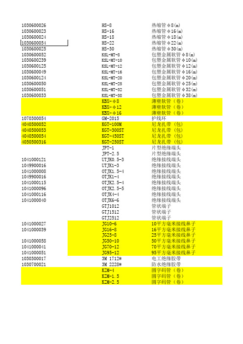
1030600026HS-8热缩管φ8(m) 1030600023HS-16热缩管φ16(m)HS-18热缩管φ18(m)HS-22热缩管φ22(m)HS-30热缩管φ30(m) 1030600052KSL-MT-8包塑金属软管φ8(m) 1030600239KSL-MT-10包塑金属软管φ10(m) 1030600125KSL-MT-12包塑金属软管φ12(m) 1030600049KSL-MT-16包塑金属软管φ16(m) 1030600124KSL-MT-20包塑金属软管φ20(m) 1030600050KSL-MT-25包塑金属软管φ25(m) 1030600051KSL-MT-32包塑金属软管φ32(m) 1030600033KSL-MT-38包塑金属软管φ38(m)KBX-φ8 薄壁软管(卷)KBX-φ12薄壁软管(卷)KBX-φ16薄壁软管(卷)1070300054GM-2015护线环4040500052KGT-100M尼龙扎带 (包) 4040500053KGT-300ST尼龙扎带 (包) 4040500054KGT-450ST尼龙扎带 (包) 4050500316KGT-250ST尼龙扎带 (包)JPT-1片型绝缘端头JPT-2.5片型绝缘端头1041000121UTJK0.5-3绝缘接线端头1049900016UTJK1-3绝缘接线端头1041000008OTJK1.5-4绝缘接线端头1049900016OTJK1-4绝缘接线端头1041000115OTJK2.5-4绝缘接线端头1041000096OTJK2.5-5绝缘接线端头1041000116OTJK4-4绝缘接线端头1041000040OTJK6-6绝缘接线端头GTJ1012管状端子GTJ1512管状端子GTJ2512管状端子1041000027JG10-610平方毫米接线鼻子1041000039JG16-816平方毫米接线鼻子JG25-825平方毫米接线鼻子1041000058JG50-1050平方毫米接线鼻子1041000041JG70-1270平方毫米接线鼻子1041000051JG95-1295平方毫米接线鼻子10303000173M 1712#电工绝缘胶带10307000213M 2228#防水绝缘胶带KZM-4圆字码管(卷)KZM-1.5圆字码管(卷)KZM-2.5圆字码管(卷)A968FX9.8.3G成品1 A968FX9.8.3G成品1 A968FX9.8.3G成品1 A968FX9.8.3G成品1 A968FX9.8.3G成品1 A968FX9.8.3G成品100 A968FX9.8.3G成品100 A968FX9.8.3G成品100 A968FX9.8.3G成品100 A968FX9.8.3G成品50 A968FX9.8.3G成品50 A968FX9.8.3G成品50 A968FX9.8.3G成品50 A968FX9.8.3G成品1 A968FX9.8.3G成品1 A968FX9.8.3G成品1 A968FX9.8.3G成品10 A968FX9.8.3G成品1 A968FX9.8.3G成品1 A968FX9.8.3G成品1 A968FX9.8.3G成品1 A968FX9.8.3G成品20 A968FX9.8.3G成品20 A968FX9.8.3G成品20 A968FX9.8.3G成品100 A968FX9.8.3G成品100 A968FX9.8.3G成品100 A968FX9.8.3G成品50 A968FX9.8.3G成品50 A968FX9.8.3G成品10 A968FX9.8.3G成品10 A968FX9.8.3G成品500 A968FX9.8.3G成品500 A968FX9.8.3G成品50 A968FX9.8.3G成品10 A968FX9.8.3G成品10 A968FX9.8.3G成品10 A968FX9.8.3G成品10 A968FX9.8.3G成品10 A968FX9.8.3G成品10 A968FX9.8.3G成品3 A968FX9.8.3G成品3 A968FX9.8.3G成品1 A968FX9.8.3G成品1 A968FX9.8.3G成品1。
HSMJ-A101-S00J1中文资料

DescriptionThis family of SMT LEDs is packaged in the industry standard PLCC-2 package. These SMT LEDs have high reliability performance and are designed to work under a wide range of environmental conditions. This high reliability feature makes them ideally suited to be used under harsh interior automotive as well as interior signs application conditions.To facilitate easy pick & place assembly, the LEDs are packed in EIA-compliant tape and reel. Every reel will be shipped in single intensity and color bin, except red color, to provide close uniformity.These LEDs are compatible with IR solder reflow process. Due to the high reliability feature of these products, they can also be mounted using through-the-wave soldering process.The super wide viewing angle at 120˚ makes these LEDs ideally suited for panel, push button, or general backlighting in automotive interior, office equipment, industrial equipment, and home appliances. The flat top emitting surface makes it easy for these LEDs to mate with light pipes. With the built-in reflector pushing up the intensity of the light output, these LEDs are also suitable to be used as LED pixels in interior elec-tronic signs.Features• Industry standard PLCC-2 package • High reliability LED package• High brightness using AlInGaP and InGaN dice tech-nologies • Available in full selection of colors • Super wide viewing angle at 120˚• Available in 8 mm carrier tape on 7 inch reel (2000 pieces)• Compatible with both IR and TTW soldering processApplications• Interior automotive– Instrument panel backlighting – Central console backlighting – Cabin backlighting • Electronic signs and signals – Interior full color sign – Variable message sign• Office automation, home appliances, industrial equipment– Front panel backlighting – Push button backlighting – Display backlightingHSMx-A10x-xxxxx PLCC-2Surface Mount LED IndicatorData SheetCAUTION: HSMN,M,K and E-A10x-xxxxx LEDs are Class 2 ESD sensitive. Please observe appropriate precau-tions during handling and processing. Refer to Avago Application Note AN-1142 for additional details.Package Dimensions(ANODE MARKING FOR AlGaAs DEVICES)TOP MOUNTREVERSE MOUNTNOTE: ALL DIMENSIONS IN MILLIMETERS.Device Selection GuideRedPart Number Min. Iv (mcd) Typ. Iv (mcd) Max. Iv (mcd) Test Current (mA) Dice Technology HSMS-A100-J00J1 4.0 15.0 - 20 GaP HSMS-A100-L00J1 10.0 15.0 - 20 GaP HSMS-A100-H70J2 .0 - 8.0 10 GaP HSMS-A100-J80J2 5.0 - 15.5 10 GaP HSMH-A100-L00J1 10.0 15.0 - 20 AlGaAs HSMH-A100-N00J1 25.0 50.0 - 20 AlGaAs HSMH-A100-L70J2 12.5 - 2.0 10 AlGaAs HSMH-A100-M80J2 20.0 - 62.0 10 AlGaAs HSMH-A100-P 0J1 40.0 - 100.0 20 AlGaAs HSMC-A100-J00J1 4.0 100.0 - 20 AlInGaP HSMC-A100-Q00J1 6 .0 100.0 - 20 AlInGaP HSMC-A100-R00J1 100.0 140.0 - 20 AlInGaP HSMC-A101-S00J1 160.0 220.0 - 20 AlInGaP HSMZ-A100-T00J1 250.0 50.0 - 20 AlInGaP HSMC-A100-P 0J1 40.0 - 100.0 20 AlInGaP HSMC-A101-R80J1 125.0 - 95.0 20 AlInGaP HSMZ-A100-S80J1 200.0 - 620.0 20 AlInGaPRed OrangePart Number Min. Iv (mcd) Typ. Iv (mcd) Max. Iv (mcd) Test Current (mA) Dice Technology HSMJ-A100-Q00J1 6 .0 100.0 - 20 AlInGaP HSMJ-A101-S00J1 160.0 200.0 - 20 AlInGaP HSMV-A100-T00J1 250.0 50.0 - 20 AlInGaP HSMJ-A100-Q 0J1 6 .0 - 155.0 20 AlInGaP HSMJ-A100-R40J1 100.0 - 15.0 20 AlInGaP HSMJ-A101-R80J1 125.0 - 95.0 20 AlInGaP HSMV-A100-S80J1 200.0 - 620.0 20 AlInGaPOrangePart Number Min. Iv (mcd) Typ. Iv (mcd) Max. Iv (mcd) Test Current (mA) Dice Technology HSMD-A100-J00J1 4.0 15.0 - 20 GaP HSMD-A100-L00J1 10.0 15.0 - 20 GaP HSMD-A100-J7PJ2 5.0 - 12.5 10 GaP HSMD-A100-K4PJ2 6. - 20.0 10 GaPHSML-A100-Q00J1 6 .0 100.0 - 20 AlInGaP HSML-A101-S00J1 160.0 220.0 - 20 AlInGaP HSML-A100-Q7PJ1 80.0 - 200.0 20 AlInGaP HSML-A100-R7PJ1 125.0 - 15.0 20 AlInGaP HSML-A101-R8WJ1 125.0 - 95.0 20 AlInGaPDevice Selection Guide, continuedYellow/AmberPart Number Min. Iv (mcd) Typ. Iv (mcd) Max. Iv (mcd) Test Current (mA) Dice Technology HSMY-A100-J00J1 4.0 12.0 - 20 GaP HSMY-A100-L00J1 10.0 12.0 - 20 GaP HSMY-A100-J 5J2 4.0 - 10.0 10 GaP HSMY-A100-K45J2 6. - 20.0 10 GaP HSMA-A100-Q00J1 6 .0 100.0 - 20 AlInGaP HSMA-A101-S00J1 160.0 220.0 - 20 AlInGaP HSMU-A100-S00J1 160.0 20.0 - 20 AlInGaP HSMA-A100-Q 5J1 6 .0 - 155.0 20 AlInGaP HSMA-A100-R45J1 100.0 - 15.0 20 AlInGaP HSMA-A101-R8WJ1 125.0 - 95.0 20 AlInGaP HSMU-A100-S4WJ1 160.0 - 500.0 20 AlInGaPYellow GreenPart Number Min. Iv (mcd) Typ. Iv (mcd) Max. Iv (mcd) Test Current (mA) Dice Technology HSMG-A100-J02J1 4.0 18.0 - 20 GaP HSMG-A100-K72J2 8.0 - 20.0 10 GaP HSME-A100-M02J1 16.0 70.0 - 20 AlInGaP HSME-A100-N82J1 0.0 - 100.0 20 AlInGaPEmerald GreenPart Number Min. Iv (mcd) Typ. Iv (mcd) Max. Iv (mcd) Test Current (mA) Dice Technology HSMG-A100-H01J1 2.5 8.0 - 20 GaP HSMG-A100-G 1J2 1.6 - 4.0 10 GaP HSMG-A100-H41J2 2.5 - 8.0 10 GaP HSME-A100-L01J1 10.0 40.0 - 20 AlInGaP HSME-A100-M PJ1 16.0 - 40.0 20 AlInGaPGreenPart Number Min. Iv (mcd) Typ. Iv (mcd) Max. Iv (mcd) Test Current (mA) Dice Technology HSMM-A101-R00J1 100.0 200.0 - 20 InGaN HSMM-A100-S00J1 160.0 50.0 - 20 InGaN HSMM-A101-Q7PJ1 80.0 - 200.0 20 InGaN HSMM-A101-R7PJ1 125.0 - 15.0 20 InGaN HSMM-A101-R8PJ1 125.0 - 95.0 20 InGaN HSMM-A100-S8PJ1 200.0 - 620.0 20 InGaNDevice Selection Guide, continuedCyanPart Number Min. Iv (mcd) Typ. Iv (mcd) Max. Iv (mcd) Test Current (mA) Dice Technology HSMK-A101-R00J1 100.0 170.0 - 20 InGaNHSMK-A100-S00J1 160.0 280.0 - 20 InGaNHSMK-A100-S8WJ1 200.0 - 620.0 20 InGaNHSMK-A101-Q WJ1 6 .0 - 155.0 20 InGaNHSMK-A101-R4WJ1 100.0 - 15.0 20 InGaNBluePart Number Min. Iv (mcd) Typ. Iv (mcd) Max. Iv (mcd) Test Current (mA) Dice Technology HSMB-A100-J00J1 4.0 15.0 - 20 GaNHSMB-A100-J70J2 5.0 - 12.5 10 GaNHSMB-A100-K80J2 8.0 - 25.0 10 GaNHSMN-A101-N00J1 25.0 50.0 - 20 InGaNHSMN-A100-P00J1 40.0 70.0 - 20 InGaNHSMN-A101-N7YJ1 0.0 - 80.0 20 InGaNHSMN-A100-P8YJ1 50.0 - 155.0 20 InGaNNote:1. The luminous intensity, I v, is measured at the mechanical axis of the lamp package. The actual peak of the spatial radiation pattern may not be aligned with this axis.Part Numbering SystemHSM x1 - A x2 x x4 -x5x6 x7 x8x9Packaging OptionColor Bin SelectionIntensity Bin SelectDevice Specific ConfigurationPackage TypeLED Chip ColorAbsolute Maximum Ratings (T A = 25°C)Parameters HSMS/D/Y/G HSMH HSMC/J/L/A HSME HSMZ/V/U HSMM/K/B/N DC Forward Current[1] 0 mA 0 mA 0 mA[ ,4]20 mA[4] 0 mA[ ,4] 0 mA Peak Forward Current[2]100 mA 100 mA 100 mA 100 mA 100 mA 100 mA Power Dissipation 6 mW 60 mW 6 mW 48 mW 72 mW 114 mW Reverse Voltage 5 VJunction Temperature 110°COperating Temperature –55°C to +100°CStorage Temperature –55°C to +100°CNotes:1. Derate linearly as shown in Figure 4.2. Duty factor = 10%, Frequency = 1 kHz.. Drive current between 10 mA and 0 mA is recommended for best long term performance.4. Operation at current below 5 mA is not recommended.Electrical Characteristics (T A = 25˚C) Forward Voltage Reverse Voltage Reverse Voltage ThermalV F (Volts) @ I F = 20 mA V R @ 100 µA V R @ 10 µA Resistance Part Number Typ. Max. Min. Min. R θJP (°C/W)HSMS/D/Y/G 2.2 2.6 5 — 180HSMH 1.9 2.6 5 — 180HSMC/J/L/A/E 1.9 2.4 5 — 280HSMZ/V/U 2.2 2.6 5 — 280HSMB .9 4. — 5 280HSMM/K/N .44.05—5280Optical Characteristics (T A = 25˚C)ViewingLuminous PeakDominant Angle Luminous Intensity/ Wavelength Wavelength [1] 2 θ1/2[2] Efficacy ηv [3] Total FluxDiceλPEAK (nm) λD (nm) (Degrees) (lm/W) I v (mcd)/Φv (mlm) Color Part Number Technology Typ. Typ. Typ. Typ. Typ.Red HSMS-A100 GaP 6 5 626 120 120 0.45 HSMH-A100 AlGaAs 645 6 7 120 6 0.45 HSMC-A10x AlInGaP 6 5 626 120 150 0.45 HSMZ-A100 AlInGaP 6 9 6 0 120 155 0.45Red HSMJ-A10x AlInGaP 621 615 120 240 0.45OrangeHSMV-A100 AlInGaP 62 617 120 26 0.45Orange HSMD-A100 GaP 600 602 120 80 0.45 HSML-A10x AlInGaP 609 605 120 20 0.45Amber HSMY-A100 GaP 58 585 120 520 0.45 HSMA-A10x AlInGaP 592 590 120 480 0.45 HSMU-A100 AlInGaP 594 592 120 500 0.45Yellow HSMG-A100 GaP 565 569 120 590 0.45Green HSME-A100 AlInGaP 575 570 120 560 0.45Emerald HSMG-A100 GaP 558 560 120 650 0.45GreenHSME-A100 AlInGaP 566 560 120 610 0.45Green HSMM-A10x InGaN 52 525 120 500 0.45Cyan HSMK-A10x InGaN 502 505 120 00 0.45Blue HSMB-A100 GaN 428 462 120 65 0.45HSMN-A10xInGaN468470120750.45Notes:1. The dominant wavelength, λD , is derived from the CIE Chromaticity Diagram and represents the color of the device.2. θ1/2 is the off-axis angle where the luminous intensity is 1/2 the peak intensity.. Radiant intensity, I e in watts/steradian, may be calculated from the equation I e = I v /ηv , where I v is the luminous intensity in candelas and ηv is the luminous efficacy in lumens/watt.Figure 1. Relative intensity vs. wavelength.Figure 2. Forward current vs. forward voltage.Figure 3. Relative intensity vs. forward current.Figure 4. Maximum forward current vs. ambient temperature. Derated based on T J MAX = 110˚C, RθJA= 500˚C/W.Figure 5. Dominant wavelength vs. forwardcurrent – InGaN devices.FORWARD VOLTAGE – V103035 F O R W A R D C U R R E N T – m A5201525Figure 4b. Maximum Forward Current Vs. Solder Point Temperature. Derated based on T J MAX = 110°C, RθJP= 180°C/W or 280°C/W.101520253035TEMPERATURE (°C)C U R R E N T - mA5101520253035TEMPERATURE (°C)C U R R E N T - m ACURRENT – mA460480540 D O M I N A N T W A V E L E N G T H – n mHSMx-A100 fig 5500470510490520530Figure 8a. Recommended SnPb reflow soldering profile.Figure 7. Radiation Pattern.D E L T A V F (N O R M A L I Z E D A T 25°C )-0.3TEMPERATURE – °C0.50.40.20.10-0.2-0.10.3Figure 6. Forward voltage shift vs. temperature.Figure 8b. Recommended Pb-free reflow soldering profile.(Acc. to J-STD-020C)TIMET E M P E R A T U R ET E M P E R A T U R E – °CNote: For detail information on reflow soldering of Avago surfaceFigure 11. Tape leader and trailer dimensions.Figure 12. Tape dimensions.Figure 13. Reel dimensions.Figure 14. Reeling orientation.11Intensity Bin Select (X5X6) Individual reel will contain parts from one half bin only.X5Min I v BinX60 Full Distributionhalf bins starting from X514 4 half bins starting from X515 5 half bins starting from X517 half bins starting from X528 4 half bins starting from X529 5 half bins starting from X52 Intensity Bin LimitsBin ID Min. (mcd) Max. (mcd) G1 1.80 2.24G2 2.24 2.80H1 2.80 .55H2 .55 4.50J1 4.50 5.60J2 5.60 7.20K1 7.20 9.00K2 9.00 11.20L1 11.20 14.00L2 14.00 18.00M1 18.00 22.40M2 22.40 28.50N1 28.50 5.50N2 5.50 45.00P1 45.00 56.00P2 56.00 71.50Q1 71.50 90.00Q2 90.00 112.50 R1 112.50 140.00 R2 140.00 180.00 S1 180.00 224.00 S2 224.00 285.00 T1 285.00 55.00 T2 55.00 450.00 U1 450.00 560.00 U2 560.00 715.00 V1 715.00 900.00 V2 900.00 1125.00 Tolerance of each bin limit = ± 12%.Color Bin Select (X7)Individual reel will contain partsfrom one full bin only.X70 Full DistributionZ A and B onlyY B and C onlyW C and D onlyV D and E onlyU E and F onlyT F and G onlyS G and H onlyQ A, B, and C onlyP B, C, and D onlyN C, D, and E onlyM D, E, and F onlyL E, F, and G onlyK F, G, and H only1 A, B, C, and D only2 E, F, G, and H onlyB, C, D, and E only4 C, D, E, and F only5 A, B, C, D, and E only6 B, C, D, E, and F onlyColor Bin LimitsBlue Min. (nm) Max. (nm)A 460.0 465.0B 465.0 470.0C 470.0 475.0D 475.0 480.0Green Min. (nm) Max. (nm)A 515.0 520.0B 520.0 525.0C 525.0 5 0.0D 5 0.0 5 5.0Cyan Min. (nm) Max. (nm)A 490.0 495.0B 495.0 500.0C 500.0 505.0D 505.0 510.0Color Bin LimitsEmeraldGreen Min. (nm) Max. (nm)A 552.5 555.5B 555.5 558.5C 558.5 561.5D 561.5 564.5Orange Min. (nm) Max. (nm)A 597.0 600.0B 600.0 60 .0C 60 .0 606.0D 606.0 609.0E 609.0 612.0Red Orange Min. (nm) Max. (nm)A 611.0 616.0B 616.0 620.0Red Min. (nm) Max. (nm)Full DistributionTolerance of each bin limit = ± 1 nm.Amber Min. (nm) Max. (nm)A 582.0 584.5B 584.5 587.0C 587.0 589.5D 589.5 592.0E 592.0 594.5F 594.5 597.0YellowGreen Min. (nm) Max. (nm)E 564.5 567.5F 567.5 570.5G 570.5 57 .5H 57 .5 576.512Packaging Option (X 8X 9)Option Test Current Package Type Reel Size J1 20 mA Top Mount 7 inch J4 20 mA Top Mount 1 inch H1 20 mA Reverse Mount 7 inch H4 20 mA Reverse Mount 1 inch J2 10 mA Top Mount 7 inch J5 10 mA Top Mount 1 inch H2 10 mA Reverse Mount 7 inch H5 10 mA Reverse Mount1 inchFor product information and a complete list of distributors, please go to our website: Avago, Avago Technologies, and the A logo are trademarks of Avago Technologies Limited in the United States and other countries.Data subject to change. Copyright © 2007 Avago Technologies Limited. All rights reserved. Obsoletes AV01-0040EN AV02-0198EN - May 30, 2007Moisture SensitivityThis product is qualified as Moisture Sensitive Level 2a per Jedec J-STD-020. Precautions when handling this moisture sensitive product is important to ensure the reliability of the product. Do refer to Avago Application Note AN5 05 Handling of Moisture Sensitive Surface Mount Devices for details.A. Storage before use- Unopen moisture barrier bag (MBB) can be stored at <40°C/90%RH for 12 months. If the actual shelf life has exceeded 12 months and the HIC indicates that baking is not required, then it is safe to reflow the LEDs per the original MSL rating.- It is not recommended to open the MBB prior to assembly (e.g. for IQC).B. Control after opening the MBB- The humidity indicator card (HIC) shall be read im-mediately upon opening of MBB.- The LEDs must be kept at < 0°C / 60%RH at all time and all high temperature related process including soldering, curing or rework need to be completed within 672 hours.C. Control for unfinished reel- For any unuse LEDs, they need to be stored in sealed MBB with desiccant or desiccator at <5%RH.D. Control of assembled boards- If the PCB soldered with the LEDs is to be subjected to other high temperature processes, the PCB need to be stored in sealed MBB with desiccant or desic-cator at <5%RH to ensure no LEDs have exceeded their floor life of 672 hours.E. Baking is required if:- “10%” or “15%” HIC indicator turns pink.- The LEDs are exposed to condition of > 0°C / 60% RH at any time.- The LEDs floor life exceeded 672 hours.Recommended baking condition: 60±5°C for 20 hours.。
GCWJ-01机舱微机监测报警系统产品说明书

GCWJ-01机舱微机监测报警系统产品说明书河南光彩电器有限公司地址:河南省安阳市太行路三枪工业园区电话:+86-0372-******* (市场部)+86-0372-******* (技术中心)传真:+86-0372-******* (市场部)+86-0372-******* (技术中心)邮编:455000电子邮箱:*********************网址:GCWJ-01 微机监测系统产品说明书一、概述GCW J-01微机监测系统主要用于船舶机舱动力装置的热工参数的测量、计算、图象显示、越限报警、记录等。
该装置的主机采用具有光彩自主知识产权的工业控制用计算机,该系统已通过CCS船检认证,整套软件在W IN2000环境下运行,该软件采用北京三维力控科技有限公司开发的PCAuto5.0最新版本,使主机具有工作效率高、反应快、显示与报警及时的特点。
二、主要功能及特点1.主机软件在W IN2000环境下运行;2.采用双机冗余运行模式,当主机出现故障时备用主机能够自动投入运行;3.具有看门狗功能,可限制非专业人员的任意操作;4.具有彩色图形显示功能(根据用户要求,可专门绘制);5.具有模拟仪表显示功能;6.具有报警列表显示功能;7.具有报警历史存档内容显示功能;8.具有打印功能;9.报警检测参数自动存储在电子存储器中,存储器容量可根据检测参数的数量适当调整,最少不少于2G;10.可根据用户要求在现场自由定义显示的内容;11.LCD/CRT上无论显示任何内容,一旦有新的报警,则报警速显窗口会自动弹出并及时发出声响报警;12.根据设定的参数,当参数越限时发出报警声,同时自动将检测点的当前参数全部存存储于电子存储器内,以备查询;13.具有报警历史查询功能;14.具有报警信息延伸功能(延伸至驾控台、轮机长室等位置);15.具有VDR延伸报警接口,可把采集的所有信息通过NMEA-0183数据格式及时传送给VDR;16.抗干扰能力强,不受外界谐波的干扰,同时不会发出谐波干扰其它设备。
MKU-A012(A018)说明书

太阳能系统工程控制柜MKU-A012控制器MKU-A018控制器说明书扬州日利达有限公司目 录 1、控制器概述1.1 整体显示画面1.2 各按键和指示灯功能简要说明2、基本功能参数2.1 主要功能2.2 测温精度2.3 温度显示范围2.4 水位显示范围2.5 输出带载功率2.6 功耗3、使用操作方法3.1 上水功能3.2 电加热功能3.3 集热循环功能3.4 管道循环功能3.5 设定模式3.5.1 进入设定功能方法3.5.2 北京时间设定3.5.3 定时上水设定3.5.4 定时加热设定3.5.5 恒温加热设定3.5.6 集热循环设定3.5.7 管道循环设3.5.8 温控出水设定3.5.9 温控上水设定3.5.10 电加热带设定3.5.11 恢复出厂设置3.5.12 通讯地址设定3.5.13 退出设定方法4、无线概述(MKU-A018 )5、输出接线示意和开孔安装尺寸5.1 输出接线示意5.2 电气柜开孔尺寸1、控制器概述1.1 整体显示画面1.2 各按键和指示灯功能简要说明说明:电源指示灯表示系统电源工作正常,其他各功能指示灯在相应的输出有输出时相应指示灯将点亮,在无输出时相应的指示灯将熄灭,5个工作按键在短按情况下将分别可以执行相应的功能,复位按键在一般情况下使用不到,在系统受干扰死机的情况下按动此按键使系统复位。
MKU-A012型无遥控, MKU-A018型附无线遥控。
2、基本功能参数2.1 主要功能2.11 水位显示2.12 5个温度显示:集热器温度、管道温度、出水口温度、电热带温度、水箱温度。
2.13 集热循环:手动、自动。
2.14 管道循环:手动、自动。
2.15 上水:手动、自动、定时、温控、防干烧、低于25%上水。
2.16 北京时间显示2.17 电加热2.18 定温出水2.19 电热带2.20 停电记忆:时间和设定的参数不丢失。
2.21 故障自检,故障保护。
2.2 测温精度: ±1℃2.3 温度显示范围: 0-100℃2.4 水位显示范围: 水位显示,Lo%-25%-50%-75%-100%2.5 输出带载功率: 每路220V输出功率500w,总输出功率<1500W2.6 功耗: <10W3、使用操作方法3.1 上水功能3.11 手动上水在水位不满的情况下按手动将可以启动手动上水,直到水箱水位达到100%将退出上水。
- 1、下载文档前请自行甄别文档内容的完整性,平台不提供额外的编辑、内容补充、找答案等附加服务。
- 2、"仅部分预览"的文档,不可在线预览部分如存在完整性等问题,可反馈申请退款(可完整预览的文档不适用该条件!)。
- 3、如文档侵犯您的权益,请联系客服反馈,我们会尽快为您处理(人工客服工作时间:9:00-18:30)。
DescriptionThis family of SMT LEDs is packaged in the industry standard PLCC-2 package. These SMT LEDs have high reliability performance and are designed to work under a wide range of environmental conditions. This high reliability feature makes them ideally suited to be used under harsh interior automotive as well as interior signs application conditions.To facilitate easy pick & place assembly, the LEDs are packed in EIA-compliant tape and reel. Every reel will be shipped in single intensity and color bin, except red color, to provide close uniformity.These LEDs are compatible with IR solder reflow process. Due to the high reliability feature of these products, they can also be mounted using through-the-wave soldering process.The super wide viewing angle at 120˚ makes these LEDs ideally suited for panel, push button, or general backlighting in automotive interior, office equipment, industrial equipment, and home appliances. The flat top emitting surface makes it easy for these LEDs to mate with light pipes. With the built-in reflector pushing up the intensity of the light output, these LEDs are also suitable to be used as LED pixels in interior elec-tronic signs.Features• Industry standard PLCC-2 package • High reliability LED package• High brightness using AlInGaP and InGaN dice tech-nologies • Available in full selection of colors • Super wide viewing angle at 120˚• Available in 8 mm carrier tape on 7 inch reel (2000 pieces)• Compatible with both IR and TTW soldering processApplications• Interior automotive– Instrument panel backlighting – Central console backlighting – Cabin backlighting • Electronic signs and signals – Interior full color sign – Variable message sign• Office automation, home appliances, industrial equipment– Front panel backlighting – Push button backlighting – Display backlightingHSMx-A10x-xxxxx PLCC-2Surface Mount LED IndicatorData SheetCAUTION: HSMN,M,K and E-A10x-xxxxx LEDs are Class 2 ESD sensitive. Please observe appropriate precau-tions during handling and processing. Refer to Avago Application Note AN-1142 for additional details.Package Dimensions(ANODE MARKING FOR AlGaAs DEVICES)TOP MOUNTREVERSE MOUNTNOTE: ALL DIMENSIONS IN MILLIMETERS.Device Selection GuideRedPart Number Min. Iv (mcd) Typ. Iv (mcd) Max. Iv (mcd) Test Current (mA) Dice Technology HSMS-A100-J00J1 4.0 15.0 - 20 GaP HSMS-A100-L00J1 10.0 15.0 - 20 GaP HSMS-A100-H70J2 .0 - 8.0 10 GaP HSMS-A100-J80J2 5.0 - 15.5 10 GaP HSMH-A100-L00J1 10.0 15.0 - 20 AlGaAs HSMH-A100-N00J1 25.0 50.0 - 20 AlGaAs HSMH-A100-L70J2 12.5 - 2.0 10 AlGaAs HSMH-A100-M80J2 20.0 - 62.0 10 AlGaAs HSMH-A100-P 0J1 40.0 - 100.0 20 AlGaAs HSMC-A100-J00J1 4.0 100.0 - 20 AlInGaP HSMC-A100-Q00J1 6 .0 100.0 - 20 AlInGaP HSMC-A100-R00J1 100.0 140.0 - 20 AlInGaP HSMC-A101-S00J1 160.0 220.0 - 20 AlInGaP HSMZ-A100-T00J1 250.0 50.0 - 20 AlInGaP HSMC-A100-P 0J1 40.0 - 100.0 20 AlInGaP HSMC-A101-R80J1 125.0 - 95.0 20 AlInGaP HSMZ-A100-S80J1 200.0 - 620.0 20 AlInGaPRed OrangePart Number Min. Iv (mcd) Typ. Iv (mcd) Max. Iv (mcd) Test Current (mA) Dice Technology HSMJ-A100-Q00J1 6 .0 100.0 - 20 AlInGaP HSMJ-A101-S00J1 160.0 200.0 - 20 AlInGaP HSMV-A100-T00J1 250.0 50.0 - 20 AlInGaP HSMJ-A100-Q 0J1 6 .0 - 155.0 20 AlInGaP HSMJ-A100-R40J1 100.0 - 15.0 20 AlInGaP HSMJ-A101-R80J1 125.0 - 95.0 20 AlInGaP HSMV-A100-S80J1 200.0 - 620.0 20 AlInGaPOrangePart Number Min. Iv (mcd) Typ. Iv (mcd) Max. Iv (mcd) Test Current (mA) Dice Technology HSMD-A100-J00J1 4.0 15.0 - 20 GaP HSMD-A100-L00J1 10.0 15.0 - 20 GaP HSMD-A100-J7PJ2 5.0 - 12.5 10 GaP HSMD-A100-K4PJ2 6. - 20.0 10 GaPHSML-A100-Q00J1 6 .0 100.0 - 20 AlInGaP HSML-A101-S00J1 160.0 220.0 - 20 AlInGaP HSML-A100-Q7PJ1 80.0 - 200.0 20 AlInGaP HSML-A100-R7PJ1 125.0 - 15.0 20 AlInGaP HSML-A101-R8WJ1 125.0 - 95.0 20 AlInGaPDevice Selection Guide, continuedYellow/AmberPart Number Min. Iv (mcd) Typ. Iv (mcd) Max. Iv (mcd) Test Current (mA) Dice Technology HSMY-A100-J00J1 4.0 12.0 - 20 GaP HSMY-A100-L00J1 10.0 12.0 - 20 GaP HSMY-A100-J 5J2 4.0 - 10.0 10 GaP HSMY-A100-K45J2 6. - 20.0 10 GaP HSMA-A100-Q00J1 6 .0 100.0 - 20 AlInGaP HSMA-A101-S00J1 160.0 220.0 - 20 AlInGaP HSMU-A100-S00J1 160.0 20.0 - 20 AlInGaP HSMA-A100-Q 5J1 6 .0 - 155.0 20 AlInGaP HSMA-A100-R45J1 100.0 - 15.0 20 AlInGaP HSMA-A101-R8WJ1 125.0 - 95.0 20 AlInGaP HSMU-A100-S4WJ1 160.0 - 500.0 20 AlInGaPYellow GreenPart Number Min. Iv (mcd) Typ. Iv (mcd) Max. Iv (mcd) Test Current (mA) Dice Technology HSMG-A100-J02J1 4.0 18.0 - 20 GaP HSMG-A100-K72J2 8.0 - 20.0 10 GaP HSME-A100-M02J1 16.0 70.0 - 20 AlInGaP HSME-A100-N82J1 0.0 - 100.0 20 AlInGaPEmerald GreenPart Number Min. Iv (mcd) Typ. Iv (mcd) Max. Iv (mcd) Test Current (mA) Dice Technology HSMG-A100-H01J1 2.5 8.0 - 20 GaP HSMG-A100-G 1J2 1.6 - 4.0 10 GaP HSMG-A100-H41J2 2.5 - 8.0 10 GaP HSME-A100-L01J1 10.0 40.0 - 20 AlInGaP HSME-A100-M PJ1 16.0 - 40.0 20 AlInGaPGreenPart Number Min. Iv (mcd) Typ. Iv (mcd) Max. Iv (mcd) Test Current (mA) Dice Technology HSMM-A101-R00J1 100.0 200.0 - 20 InGaN HSMM-A100-S00J1 160.0 50.0 - 20 InGaN HSMM-A101-Q7PJ1 80.0 - 200.0 20 InGaN HSMM-A101-R7PJ1 125.0 - 15.0 20 InGaN HSMM-A101-R8PJ1 125.0 - 95.0 20 InGaN HSMM-A100-S8PJ1 200.0 - 620.0 20 InGaNDevice Selection Guide, continuedCyanPart Number Min. Iv (mcd) Typ. Iv (mcd) Max. Iv (mcd) Test Current (mA) Dice Technology HSMK-A101-R00J1 100.0 170.0 - 20 InGaNHSMK-A100-S00J1 160.0 280.0 - 20 InGaNHSMK-A100-S8WJ1 200.0 - 620.0 20 InGaNHSMK-A101-Q WJ1 6 .0 - 155.0 20 InGaNHSMK-A101-R4WJ1 100.0 - 15.0 20 InGaNBluePart Number Min. Iv (mcd) Typ. Iv (mcd) Max. Iv (mcd) Test Current (mA) Dice Technology HSMB-A100-J00J1 4.0 15.0 - 20 GaNHSMB-A100-J70J2 5.0 - 12.5 10 GaNHSMB-A100-K80J2 8.0 - 25.0 10 GaNHSMN-A101-N00J1 25.0 50.0 - 20 InGaNHSMN-A100-P00J1 40.0 70.0 - 20 InGaNHSMN-A101-N7YJ1 0.0 - 80.0 20 InGaNHSMN-A100-P8YJ1 50.0 - 155.0 20 InGaNNote:1. The luminous intensity, I v, is measured at the mechanical axis of the lamp package. The actual peak of the spatial radiation pattern may not be aligned with this axis.Part Numbering SystemHSM x1 - A x2 x x4 -x5x6 x7 x8x9Packaging OptionColor Bin SelectionIntensity Bin SelectDevice Specific ConfigurationPackage TypeLED Chip ColorAbsolute Maximum Ratings (T A = 25°C)Parameters HSMS/D/Y/G HSMH HSMC/J/L/A HSME HSMZ/V/U HSMM/K/B/N DC Forward Current[1] 0 mA 0 mA 0 mA[ ,4]20 mA[4] 0 mA[ ,4] 0 mA Peak Forward Current[2]100 mA 100 mA 100 mA 100 mA 100 mA 100 mA Power Dissipation 6 mW 60 mW 6 mW 48 mW 72 mW 114 mW Reverse Voltage 5 VJunction Temperature 110°COperating Temperature –55°C to +100°CStorage Temperature –55°C to +100°CNotes:1. Derate linearly as shown in Figure 4.2. Duty factor = 10%, Frequency = 1 kHz.. Drive current between 10 mA and 0 mA is recommended for best long term performance.4. Operation at current below 5 mA is not recommended.Electrical Characteristics (T A = 25˚C) Forward Voltage Reverse Voltage Reverse Voltage ThermalV F (Volts) @ I F = 20 mA V R @ 100 µA V R @ 10 µA Resistance Part Number Typ. Max. Min. Min. R θJP (°C/W)HSMS/D/Y/G 2.2 2.6 5 — 180HSMH 1.9 2.6 5 — 180HSMC/J/L/A/E 1.9 2.4 5 — 280HSMZ/V/U 2.2 2.6 5 — 280HSMB .9 4. — 5 280HSMM/K/N .44.05—5280Optical Characteristics (T A = 25˚C)ViewingLuminous PeakDominant Angle Luminous Intensity/ Wavelength Wavelength [1] 2 θ1/2[2] Efficacy ηv [3] Total FluxDiceλPEAK (nm) λD (nm) (Degrees) (lm/W) I v (mcd)/Φv (mlm) Color Part Number Technology Typ. Typ. Typ. Typ. Typ.Red HSMS-A100 GaP 6 5 626 120 120 0.45 HSMH-A100 AlGaAs 645 6 7 120 6 0.45 HSMC-A10x AlInGaP 6 5 626 120 150 0.45 HSMZ-A100 AlInGaP 6 9 6 0 120 155 0.45Red HSMJ-A10x AlInGaP 621 615 120 240 0.45OrangeHSMV-A100 AlInGaP 62 617 120 26 0.45Orange HSMD-A100 GaP 600 602 120 80 0.45 HSML-A10x AlInGaP 609 605 120 20 0.45Amber HSMY-A100 GaP 58 585 120 520 0.45 HSMA-A10x AlInGaP 592 590 120 480 0.45 HSMU-A100 AlInGaP 594 592 120 500 0.45Yellow HSMG-A100 GaP 565 569 120 590 0.45Green HSME-A100 AlInGaP 575 570 120 560 0.45Emerald HSMG-A100 GaP 558 560 120 650 0.45GreenHSME-A100 AlInGaP 566 560 120 610 0.45Green HSMM-A10x InGaN 52 525 120 500 0.45Cyan HSMK-A10x InGaN 502 505 120 00 0.45Blue HSMB-A100 GaN 428 462 120 65 0.45HSMN-A10xInGaN468470120750.45Notes:1. The dominant wavelength, λD , is derived from the CIE Chromaticity Diagram and represents the color of the device.2. θ1/2 is the off-axis angle where the luminous intensity is 1/2 the peak intensity.. Radiant intensity, I e in watts/steradian, may be calculated from the equation I e = I v /ηv , where I v is the luminous intensity in candelas and ηv is the luminous efficacy in lumens/watt.Figure 1. Relative intensity vs. wavelength.Figure 2. Forward current vs. forward voltage.Figure 3. Relative intensity vs. forward current.Figure 4. Maximum forward current vs. ambient temperature. Derated based on T J MAX = 110˚C, RθJA= 500˚C/W.Figure 5. Dominant wavelength vs. forwardcurrent – InGaN devices.FORWARD VOLTAGE – V103035 F O R W A R D C U R R E N T – m A5201525Figure 4b. Maximum Forward Current Vs. Solder Point Temperature. Derated based on T J MAX = 110°C, RθJP= 180°C/W or 280°C/W.101520253035TEMPERATURE (°C)C U R R E N T - mA5101520253035TEMPERATURE (°C)C U R R E N T - m ACURRENT – mA460480540 D O M I N A N T W A V E L E N G T H – n mHSMx-A100 fig 5500470510490520530Figure 8a. Recommended SnPb reflow soldering profile.Figure 7. Radiation Pattern.D E L T A V F (N O R M A L I Z E D A T 25°C )-0.3TEMPERATURE – °C0.50.40.20.10-0.2-0.10.3Figure 6. Forward voltage shift vs. temperature.Figure 8b. Recommended Pb-free reflow soldering profile.(Acc. to J-STD-020C)TIMET E M P E R A T U R ET E M P E R A T U R E – °CNote: For detail information on reflow soldering of Avago surfaceFigure 11. Tape leader and trailer dimensions.Figure 12. Tape dimensions.Figure 13. Reel dimensions.Figure 14. Reeling orientation.11Intensity Bin Select (X5X6) Individual reel will contain parts from one half bin only.X5Min I v BinX60 Full Distributionhalf bins starting from X514 4 half bins starting from X515 5 half bins starting from X517 half bins starting from X528 4 half bins starting from X529 5 half bins starting from X52 Intensity Bin LimitsBin ID Min. (mcd) Max. (mcd) G1 1.80 2.24G2 2.24 2.80H1 2.80 .55H2 .55 4.50J1 4.50 5.60J2 5.60 7.20K1 7.20 9.00K2 9.00 11.20L1 11.20 14.00L2 14.00 18.00M1 18.00 22.40M2 22.40 28.50N1 28.50 5.50N2 5.50 45.00P1 45.00 56.00P2 56.00 71.50Q1 71.50 90.00Q2 90.00 112.50 R1 112.50 140.00 R2 140.00 180.00 S1 180.00 224.00 S2 224.00 285.00 T1 285.00 55.00 T2 55.00 450.00 U1 450.00 560.00 U2 560.00 715.00 V1 715.00 900.00 V2 900.00 1125.00 Tolerance of each bin limit = ± 12%.Color Bin Select (X7)Individual reel will contain partsfrom one full bin only.X70 Full DistributionZ A and B onlyY B and C onlyW C and D onlyV D and E onlyU E and F onlyT F and G onlyS G and H onlyQ A, B, and C onlyP B, C, and D onlyN C, D, and E onlyM D, E, and F onlyL E, F, and G onlyK F, G, and H only1 A, B, C, and D only2 E, F, G, and H onlyB, C, D, and E only4 C, D, E, and F only5 A, B, C, D, and E only6 B, C, D, E, and F onlyColor Bin LimitsBlue Min. (nm) Max. (nm)A 460.0 465.0B 465.0 470.0C 470.0 475.0D 475.0 480.0Green Min. (nm) Max. (nm)A 515.0 520.0B 520.0 525.0C 525.0 5 0.0D 5 0.0 5 5.0Cyan Min. (nm) Max. (nm)A 490.0 495.0B 495.0 500.0C 500.0 505.0D 505.0 510.0Color Bin LimitsEmeraldGreen Min. (nm) Max. (nm)A 552.5 555.5B 555.5 558.5C 558.5 561.5D 561.5 564.5Orange Min. (nm) Max. (nm)A 597.0 600.0B 600.0 60 .0C 60 .0 606.0D 606.0 609.0E 609.0 612.0Red Orange Min. (nm) Max. (nm)A 611.0 616.0B 616.0 620.0Red Min. (nm) Max. (nm)Full DistributionTolerance of each bin limit = ± 1 nm.Amber Min. (nm) Max. (nm)A 582.0 584.5B 584.5 587.0C 587.0 589.5D 589.5 592.0E 592.0 594.5F 594.5 597.0YellowGreen Min. (nm) Max. (nm)E 564.5 567.5F 567.5 570.5G 570.5 57 .5H 57 .5 576.512Packaging Option (X 8X 9)Option Test Current Package Type Reel Size J1 20 mA Top Mount 7 inch J4 20 mA Top Mount 1 inch H1 20 mA Reverse Mount 7 inch H4 20 mA Reverse Mount 1 inch J2 10 mA Top Mount 7 inch J5 10 mA Top Mount 1 inch H2 10 mA Reverse Mount 7 inch H5 10 mA Reverse Mount1 inchFor product information and a complete list of distributors, please go to our website: Avago, Avago Technologies, and the A logo are trademarks of Avago Technologies Limited in the United States and other countries.Data subject to change. Copyright © 2007 Avago Technologies Limited. All rights reserved. Obsoletes AV01-0040EN AV02-0198EN - May 30, 2007Moisture SensitivityThis product is qualified as Moisture Sensitive Level 2a per Jedec J-STD-020. Precautions when handling this moisture sensitive product is important to ensure the reliability of the product. Do refer to Avago Application Note AN5 05 Handling of Moisture Sensitive Surface Mount Devices for details.A. Storage before use- Unopen moisture barrier bag (MBB) can be stored at <40°C/90%RH for 12 months. If the actual shelf life has exceeded 12 months and the HIC indicates that baking is not required, then it is safe to reflow the LEDs per the original MSL rating.- It is not recommended to open the MBB prior to assembly (e.g. for IQC).B. Control after opening the MBB- The humidity indicator card (HIC) shall be read im-mediately upon opening of MBB.- The LEDs must be kept at < 0°C / 60%RH at all time and all high temperature related process including soldering, curing or rework need to be completed within 672 hours.C. Control for unfinished reel- For any unuse LEDs, they need to be stored in sealed MBB with desiccant or desiccator at <5%RH.D. Control of assembled boards- If the PCB soldered with the LEDs is to be subjected to other high temperature processes, the PCB need to be stored in sealed MBB with desiccant or desic-cator at <5%RH to ensure no LEDs have exceeded their floor life of 672 hours.E. Baking is required if:- “10%” or “15%” HIC indicator turns pink.- The LEDs are exposed to condition of > 0°C / 60% RH at any time.- The LEDs floor life exceeded 672 hours.Recommended baking condition: 60±5°C for 20 hours.。