ECE R90 第2版 第1次勘误
1N69统计学概要97年10月20日二版勘误表

(1N69)統計學(概要)(97年10月20日二版)勘誤表P.1第二段第二行第一個字 「及」應改為「計」。
P.31第13題解析(f +1-f M0)應更正為(f M0-f +1)。
P.7第18題答案修正為(A )P.10第(5)項原:資料歸屬應包含上限而不包含下限 修正為:資料歸屬應包含下限而不包含上限P.30第9題題目修正為:下列何者敘述「正確」? 答案修正為(全)解析更正為,資料的歸屬應包含下限而不包含上限P.97第5題選項(C )修正為0.376 解析修正為:X 服從二項分配(10,0.2)()()()91101100108.02.08.02.01C C X P +=≤=0.3758(約0.376)P.102第23題 答案修正為無解P.125第15題選項(C)應改為0.0228,另外更正解析(2)0.0228P Z ≥=P.127第20題選項(A)應改為75,100,另外更正解析22[(7075)..........]5100S =-+÷=P.127 第23題本題答案選項(C)0.6844,更正為0.6736。
【解析】220-225/125開根號=5/11.1803398874=0.4472=>四捨五入後約0.45P(Z≧-0.45)=0.6736P.153第22題本題答案更正為「無解」。
P.174第2題【解析】型I 誤差(type Ierror)當虛無假設H0為真,卻因抽樣誤差導致決策為拒絕H0,此種誤差稱為型I誤差。
型II誤差(type II error)當虛無假設H0為假,卻因抽樣誤差導致決策不拒絕H0,此種誤差稱為型II誤差。
故本題答案,應修正為(B)P.203第9題本題答案選項(C)3.94,更正為(C)3.54。
解析中,3.94更正為3.54P.203第10題本題答案選項(B)F0=36.548,應更正為40.678。
【解析】分子:32/2=16分母:3.54/9=0.3933333計算:16/0.3933333=40.678P.251第6題選項(C)修正為「有,Q=14.749」解析修正為:P.252 第四行Q =(28-33.33)233.33 +(48-36.67)236.67 +(19-10)210 +(32-33.33)233.33 …=19.249 修正為:Q =(28-33.33)233.33 +(48-36.67)236.67 +(4-10)210 +(32-33.33)233.33 …=14.749刪除下段文字:→採H 0的決策,即此五種牌子的洗髮精之品質並無差異。
欧盟汽车标准法规体系ECE

72
ECE R48
关于就照明装置和光信号装置安装方面认证车辆的统一规定
95
ECE R49 ECE R50
关于就发动机污染物排放方面认证压燃式认发动机,天然气 发动机和燃用液化石油气的点燃式发动机以及装有这些发动 机的车辆的统一规定 关于批准轻便摩托车、摩托车及其类似车辆前后位置灯、制 灯、转向信号灯和后牌照板照明装置的统一规定 关于就噪声方面认证机动车辆(至少四轮)的统一规定 关于M2 和M3 类小型车辆结构认证的统一规定
30
ECE R80
76
ECE R83
关于根据发动机燃油要求就污染物排放方面认证车辆的统一 规定
493
ECE R84 ECE R85
ECE R87 ECE R88 ECE R89 ECE R90
关于就油耗测量方面认证装有内燃机的轿车的统一规定 就净功率测量问题对用作M 类和N 类机动车辆动力装置的内 燃机进行认证的统一规定 用于驱动M 类和N 类汽车的内燃机净功率或电力驱动机构 30min 最大功率测量认证的统一规定 关于认证机动车辆昼行灯方面的统一规定 关于批准摩托车反光轮胎的统一规定 关于1.有关车辆最高车速限制方面的车辆认证。2. 有关在车 辆上安装型式已通过认证的车速限制装置(SLD)的车辆认 证3.车速限制装置(SLD) 的认证 关于认证机动车辆及其挂车的替换用制动衬片总成和替换用 鼓式制动器衬片的统一规定
25
ECE R12
关于防止在汽车碰撞时转向机构对驾驶员的伤害认证的统一 规定
65
ECE R13
关于就制动方面批准M 类、N 类和O 类车辆的统一规定
308
ECE R13H
关于乘用车制动方面认证的统一规定
93
ECE R14
人民交通出版社勘误表-发输变电-20140720

(9000 8000 10000) 22500kVA 2 60%
一、二级负荷: S2 9000 8000 17000kVA 取以上结果的较大值,主变压器容量至少为 22500kVA,因此选 27000kVA。 注:原题考查旧规,新规《35kV~110kV 变电站设计规范》(GB 50059-2011) 中已无 60%的要求。 7. P294,第 2 题答案修正为 B,依据修正如下: 《电力工程电气设计手册》(电力一次部分) P120 表 4-1 和 4-2、式 4-10 及 P129 式 4-20 由于时间仓促,编纂中存在错误与瑕疵,勘误将及时更新,对由此带来的不便,我社表示诚挚的歉意
3 U 3 3.1757 500 1323cm 4 Ke 4 0.9
复合绝缘子要求的最小爬电距离: L2 2.8 500 1400cm ,取两者之较大者,为 1400mm。
由于时间仓促,编纂中存在错误与瑕疵,勘误将及时更新,对由此带来的不便,我社表示诚挚的歉意
2014 年注册电气工程师(发输变电)执业资格考试专业考试历年真题详解
Tpy1 4 92.85 425.24 25% 39484 N
注:《电力工程高压送电线路设计手册》(第二版) P328 表 6-2-6 下方文字“两分裂以上导线的纵向不平衡 张力,对平地、丘陵及山地线路,应分别取不小于一相导线最大使用张力的 15%、20%及 25%,且均不小 于 20kN。 14. P383,第 34 题答案修正为 A,解析修正如下: 《110kV~750kV 架空输电线路设计规范》(GB 50545-2010) 第 10.1.7 条表 10.1.7 山区的 0˚耐张塔塔导线断线张力为最大使用张力的 70%,根据题干已知条件,则:
《电力工程电气设计手册1电气一次部分》勘误---2017-06-11
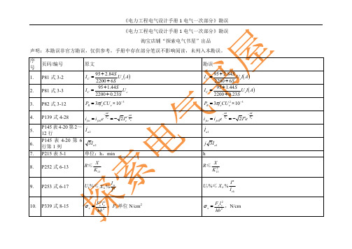
I a1
j 3I a1
h R≤
X 2 K13 I I ek
9.
P253 式 6-17
Uy%≤ X k %
In I
Uy%≤ X k %
10.
P339 式 8-15
x
Fx2 le2 ,Fx 单位 N/cm2 2 hb
x
Fx l c2 ,N/cm hb 2
《电力工程电气设计手册 1 电气一次部分》勘误 序 号 11. 12. 13. 14. 15. 页码/编号 P341 式 8-20 P344 式 8-43 原文
95 2.84 S U e A 2200 6 S 95 1.44 S IC Ue 2200 0.23S IC
勘误
95 2.84 S U el A 2200 6 S 95 1.44 S IC U e l A 2200 0.23S IC
PR 3f eCU e 103
P480 式 9-10
I cn I n
nX S nX S nX L XC n
I cn I n
nX S nX S nX L XC n
25. 26. 27. 28.
P536 式 9-53 P544【例】
X0
3 XL X 12 3 X L
X0
2 XL X 12 3 X L
X A2C1 X A2 A1,X A2 B1
4
2l 0.628 10 ln 1 D 1
30. 31.
P574 式 10-4 P701 式附 10-25
l j1
24 U A3
l j1
24 U A2
RCC-M 2000版+2002补遗中文版勘误表
“Ke mech”
倒数第2段
B/94 B3000/145 B3683.5 b) “C3=0.1+0.03(D0/t),但不大于2.0。” “C3=1.0+0.03(D0/t),但不大于2.0。” 英文原文有误
RCC-M 2000版+2002补遗中文版勘误
B篇 第2页
B篇 1级设备
中文 英文版 版页码 页码
“——又回复到常态。” “有出现过渡变形和破坏的危险” “塑牲变形”
“——又恢复到常态。” “有出现过度变形和破坏的危险” “塑性变形”
第1段
1、“可孔封头或多孔筒体” 2、“弯曲应力(除由整体结构不连续性 引起的外)” 3、“在垂至于管道轴线的截面上平均的 总体薄膜应力”
1、“多孔封头和多孔筒体” 2、“弯曲应力(由整体结构不连续性引 起的除外)” 3、“在垂直于管道轴线的截面上平均的 总体薄膜应力”
ri
I + Tr
”
Gb定义
B/51 B3000/69 B3544.1 c) “r3≥0.1Tr或0.3h中较大者。”
“r3≥0.1Tr或0.1h中较大者。”
B/51
B3000/92 图B3544.1.b
“
r3
≥
⎧⎨⎩00,,11Thr
⎫ ⎬ ⎭
”
“
r3
≥
⎧⎨⎩00..11Thr
⎫ ⎬ ⎭
”
英文原文有误
备规格书所指明的与各类工况相关联的 备规格书所指明的与各类工况相关联的
荷载作用下”
载荷作用下”
“本部分新增加的要求用ISO标准术语进 “本部分用ISO标准术语对附加要求进行
行描述。”
了描述。”
“所有的供货商,当进行的活动可能影响 “所有的供货商,当进行的活动可能影响
ECE R99 第2版
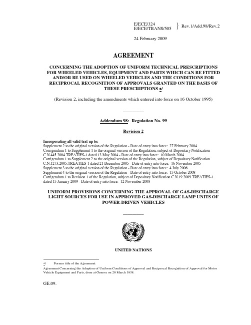
}Rev.1/Add.98/Rev.2E/ECE/324E/ECE/TRANS/50524 February 2009AGREEMENTCONCERNING THE ADOPTION OF UNIFORM TECHNICAL PRESCRIPTIONS FOR WHEELED VEHICLES, EQUIPMENT AND PARTS WHICH CAN BE FITTED AND/OR BE USED ON WHEELED VEHICLES AND THE CONDITIONS FOR RECIPROCAL RECOGNITION OF APPROVALS GRANTED ON THE BASIS OFTHESE PRESCRIPTIONS /(Revision 2, including the amendments which entered into force on 16 October 1995)_________Addendum 98: Regulation No. 99Revision 2Incorporating all valid text up to:Supplement 2 to the original version of the Regulation - Date of entry into force: 27 February 2004 Corrigendum 1 to Supplement 1 to the original version of the Regulation, subject of Depositary NotificationC.N.445.2004.TREATIES-1 dated 13 May 2004 - Date of entry into force: 10 March 2004Corrigendum 1 to Supplement 2 to the original version of the Regulation, subject of Depositary NotificationC.N.1273.2005.TREATIES-1 dated 21 December 2005 - Date of entry into force: 16 November 2005 Supplement 3 to the original version of the Regulation - Date of entry into force: 4 July 2006Supplement 4 to the original version of the Regulation - Date of entry into force: 15 October 2008 Corrigendum 1 to Revision 1 of the Regulation, subject of Depositary Notification C.N.19.2009.TREATIES-1 dated 15 January 2009 - Date of entry into force: 12 November 2008UNIFORM PROVISIONS CONCERNING THE APPROVAL OF GAS-DISCHARGE LIGHT SOURCES FOR USE IN APPROVED GAS-DISCHARGE LAMP UNITS OFPOWER-DRIVEN VEHICLES_________UNITED NATIONS∗/ Former title of the Agreement:Agreement Concerning the Adoption of Uniform Conditions of Approval and Reciprocal Recognition of Approval for Motor Vehicle Equipment and Parts, done at Geneva on 20 March 1958.GE.09-}Rev.1/Add.98/Rev.2E/ECE/324E/ECE/TRANS/505Regulation No. 99page 3Regulation No. 99UNIFORM PROVISIONS CONCERNING THE APPROVAL OF GAS-DISCHARGE LIGHT SOURCES FOR USE IN APPROVED GAS-DISCHARGE LAMP UNITS OF POWER-DRIVEN VEHICLESCONTENTSREGULATION Page1. Scope (5)2. Administrative provisions (5)2.1. Definitions (5)2.2. Application for approval (5)2.3. Inscriptions (6)2.4. Approval (6)3. Technical requirements (8)3.1. Definitions (8)3.2. General specifications (8)3.3. Manufacture (9)3.4. Tests (9)3.5. Position and dimensions of electrodes, arc and stripes (9)3.6. Starting, run-up and hot restrike characteristics (10)3.7. Electrical characteristics (10)3.8. Luminous flux (11)3.9. Colour (11)3.10. UV radiation (11)3.11. Standard gas-discharge light sources (12)E/ECE/324}Rev.1/Add.98/Rev.2E/ECE/TRANS/505Regulation No. 99page 4CONTENTS (continued)4. Conformity of production (13)5. Penalties for non-conformity of production (14)6. Production definitely discontinued (14)7. Names and addresses of Technical Servicesresponsible for conducting approval tests,and of Administrative Departments (14)ANNEXESAnnex 1 Sheets for gas-discharge light sourcesAnnex 2 Communication concerning the approval (or extension or refusal or withdrawal of approval or production definitely discontinued) of a type of gas-discharge lightsource pursuant to Regulation No. 99Annex 3 Example of a type of approval markAnnex 4 Method of measurement of electrical and photometric characteristicsAnnex 5 Optical set-up for the measurement of the position and form of the arcand of the position of the electrodesAnnex 6 Minimum requirements for quality procedures by the manufacturerAnnex 7 Sampling and compliance levels for manufacturer’s test recordsAnnex 8 Minimum requirements for sampling by an inspector}Rev.1/Add.98/Rev.2E/ECE/324E/ECE/TRANS/505Regulation No. 99page 51. SCOPEThis Regulation applies to gas-discharge light sources shown in Annex 1 and intendedfor use in approved gas-discharge lamp units of power-driven vehicles.2. ADMINISTRATIVE PROVISIONS2.1. Definitions2.1.1. The term "category" is used in this Regulation to describe different basic design ofstandardized gas-discharge light sources. Each category has a specific designation, asfor example: "D2S".2.1.2. Gas-discharge light sources of different "types" are gas-discharge light sources withinthe same category which differ in such essential respects as:2.1.2.1. trade name or mark; 1/2.1.2.2. bulb design, in so far as these differences affect the optical results;2.2. Application for approval2.2.1. Application for approval shall be submitted by the owner of the trade name or mark, orby his duly accredited representative.2.2.2. Every application for approval shall be accompanied (see also paragraph 2.4.2.) by: 2.2.2.1. drawings in triplicate, sufficiently detailed to permit identification of the type;2.2.2.2. a technical description including ballast identification;2.2.2.3. three samples of each colour which has been applied for;2.2.2.4. one sample of the ballast.2.2.3. In the case of a type of gas-discharge light source differing only by the trade name ormark from a type that has already been approved it shall be sufficient to submit:1/ Gas-discharge light sources bearing the same trade name or mark but produced by different manufacturers are considered as being of different types. Gas-discharge light sources produced by the same manufacturer differing only by the trade name or mark may be considered to be of the same type.E/ECE/324}Rev.1/Add.98/Rev.2E/ECE/TRANS/505Regulation No. 99page 62.2.3.1. a declaration by the manufacturer that the type submitted is identical (except in thetrade name or mark) to and has been produced by the same manufacturer as, the typealready approved, the latter being identified by its approval code;2.2.3.2. two samples bearing the new trade name or mark.2.2.4. The Competent Authority shall verify the existence of satisfactory arrangements forensuring effective control of the conformity of production before type approval isgranted.2.3. Inscriptions2.3.1. Gas-discharge light sources submitted for approval shall bear on the cap or bulb:2.3.1.1. the trade name or mark of the applicant;2.3.1.2. the international designation of the relevant category;2.3.1.3. the rated wattage; this need not to be indicated separately if it is part of theinternational designation of the relevant category;2.3.1.4. a space of sufficient size to accommodate the approval mark.2.3.2. The space mentioned in paragraph 2.3.1.4. shall be indicated in the drawingsaccompanying the application for approval.2.3.3.Other inscriptions than those covered by paragraphs 2.3.1. and 2.4.4. may be affixedon the cap.2.3.4. The ballast used for the type approval of the light source shall be marked with typeand trade mark identification and with the rated voltage and wattage, as indicated onthe relevant lamp data sheet,2.4. Approval2.4.1. If all samples of a type of gas-discharge light source which are submitted inaccordance with paragraphs 2.2.2.3. or 2.2.3.2. comply with the requirements of thisRegulation when tested with the ballast according to paragraph 2.2.2.4., approval shallbe granted.2.4.2. An approval code shall be assigned to each type approved. Its first character shallindicate the series of amendments incorporating the most recent major technicalamendments made to the Regulation at the time of issue of the approval.}Rev.1/Add.98/Rev.2E/ECE/324E/ECE/TRANS/505Regulation No. 99page 7This will be followed by an identification code comprising not more than twocharacters. Only the Arabic numerals and capital letters listed in footnote 2/ shall beused.The same Contracting Party may not assign the same code to another type of gas-discharge light source.2.4.3. Notice of approval or of extension or refusal or withdrawal of approval or productiondefinitely discontinued of a type of gas-discharge light source pursuant to thisRegulation shall be communicated to the Parties of the Agreement which apply thisRegulation by means of a form conforming to the model in Annex 2 to this Regulationand of a drawing, supplied by the applicant for approval in a format not exceeding A4(210 x 297 mm) and on a scale of at least 2 : 1.2.4.4. To every gas-discharge light source conforming to a type approved under thisRegulation there shall be affixed in the space referred to in paragraph 2.3.1.4., inaddition to the inscriptions required under paragraph 2.3.1., an international approvalmark consisting of:2.4.4.1. a truncated circle surrounding the letter "E" followed by the distinguishing number ofthe country which has granted approval; 3/2.4.4.2. the approval code, placed close to the truncated circle.2/ 0 1 2 3 4 5 6 7 8 9A B C D E F G H J K L M N P R S T U V W X Y Z3/ 1 for Germany, 2 for France, 3 for Italy, 4 for the Netherlands, 5 for Sweden, 6 for Belgium, 7 for Hungary, 8 for the Czech Republic, 9 for Spain, 10 for Serbia, 11 for the United Kingdom, 12 for Austria, 13 for Luxembourg, 14 for Switzerland, 15 (vacant), 16 for Norway, 17 for Finland, 18 for Denmark, 19 for Romania, 20 for Poland, 21 for Portugal, 22 for the Russian Federation, 23 for Greece, 24 for Ireland, 25 for Croatia, 26 for Slovenia, 27 for Slovakia, 28 for Belarus, 29 for Estonia, 30 (vacant), 31 for Bosnia and Herzegovina, 32 for Latvia, 33 (vacant), 34 for Bulgaria, 35 (vacant), 36 for Lithuania, 37 for Turkey, 38 (vacant), 39 for Azerbaijan, 40 for The former Yugoslav Republic of Macedonia, 41 (vacant), 42 for the European Community (Approvals are granted by its Member States using their respective ECE symbol), 43 for Japan, 44 (vacant), 45 for Australia, 46 for Ukraine, 47 for South Africa, 48 for New Zealand, 49 for Cyprus, 50 for Malta, 51 for the Republic of Korea, 52 for Malaysia, 53 for Thailand, 54 and 55 (vacant), 56 for Montenegro, 57 (vacant) and 58 for Tunisia. Subsequent numbers shall be assigned to other countries in the chronological order in which they ratify or accede to the Agreement Concerning the Adoption of Uniform Technical Prescriptions for Wheeled Vehicles, Equipment and Parts which can be Fitted and/or be Used on Wheeled Vehicles and the Conditions for Reciprocal Recognition of Approvals Granted on the Basis of these Prescriptions, and the numbers thus assigned shall be communicated by the Secretary-General of the United Nations to the Contracting Parties to the Agreement.E/ECE/324}Rev.1/Add.98/Rev.2E/ECE/TRANS/505Regulation No. 99page 82.4.5. If the applicant has obtained the same approval code for several trade names or marks,one or more of them will suffice to meet the requirements of paragraph 2.3.1.1.2.4.6. The marks and inscriptions specified in paragraphs 2.3.1. and 2.4.3. shall be clearlylegible and be indelible.2.4.7. Annex 3 to this Regulation gives an example of arrangement of the approval mark.3. TECHNICAL REQUIREMENTS3.1. Definitions3.1.1. "Gas-discharge light source": light source in which the light is produced by astabilized discharge arc.3.1.2. "Ballast": Specific electrical supply for the gas-discharge light source.3.1.3. "Rated voltage": Input voltage marked on the ballast.3.1.4. "Rated wattage": Wattage marked on the gas-discharge light source and ballast.3.1.5. "Test voltage": Voltage, at the input terminals of the ballast for which the electricaland photometric characteristics of the gas-discharge light source are intended and areto be tested.3.1.6. "Objective value": Design value of an electrical or photometric characteristic. To beachieved, within the specified tolerances, when the gas-discharge light source isenergized by the ballast operated at test voltage.3.1.7. "Standard (etalon) gas-discharge light source": Special gas-discharge light source usedfor the testing of headlamps. It has reduced dimensional, electrical and photometriccharacteristics as specified on the relevant data sheet.3.1.8. "Reference axis": An axis defined with reference to the cap and to which certaindimensions of the gas-discharge light source are referred.3.1.9. "Reference plane": a plane defined with reference to the cap and to which certaindimensions of the gas-discharge light source are referred.3.2. General specifications3.2.1. Each sample submitted shall conform to the relevant specifications of this Regulationwhen tested with the ballast according to paragraph 2.2.2.4.}Rev.1/Add.98/Rev.2E/ECE/324E/ECE/TRANS/505Regulation No. 99page 93.2.2. Gas-discharge light sources shall be so designed as to be and to remain in goodworking order when in normal use. They shall moreover exhibit no fault in design ormanufacture.3.3. Manufacture3.3.1. The bulb of the gas-discharge light source shall exhibit no scores or spots which mightimpair their efficiency and their optical performance.3.3.2. In the case of a coloured (outer) bulb, after an operating period of 15 hours with theballast at test voltage, the surface of the bulb shall be lightly wiped with a cotton clothsoaked in a mixture of 70 volume per cent of n-heptane and 30 volume per cent oftoluol. After about five minutes, the surface shall be inspected visually. It shall notshow any apparent changes.3.3.3. Gas-discharge light sources shall be equipped with standard caps complying with thecap data sheets of IEC Publication 60061, third edition, as specified on the individualdata sheets of Annex 1.3.3.4. The cap shall be strong and firmly secured to the bulb.3.3.5. To ascertain whether gas-discharge light sources conform to the requirements ofparagraphs 3.3.3. to 3.3.4., a visual inspection, a dimension check and, whereappropriate, a trial fitting shall be carried out.3.4. Tests3.4.1. Gas-discharge light sources shall be aged as indicated in Annex 4.3.4.2. All samples shall be tested with the ballast, according to paragraph 2.2.2.4.3.4.3. Electrical measurements shall be carried out with instruments of at least class 0.2.(0.2 per cent full scale accuracy).3.5. Position and dimensions of electrodes, arc and stripes3.5.1. The geometric position of the electrodes shall be as specified on the relevant datasheet. An example of a method of measuring arc and electrodes position is given inAnnex 5. Other methods may be used.3.5.1.1. The position and dimensions of the light source electrodes shall be measured beforethe ageing period, the gas-discharge light source unlit and using optical methodsthrough the glass envelope.E/ECE/324}Rev.1/Add.98/Rev.2E/ECE/TRANS/505Regulation No. 99page 103.5.2. The shape and the displacement of the arc shall conform to the requirements as givenon the relevant data sheet.3.5.2.1. The measurement shall be made after ageing with the light source supplied by theballast at test voltage.3.5.3. The position and dimension and transmission of the stripes shall comply with therequirements as given on the relevant data sheet.3.5.3.1. The measurement shall be made after ageing with the light source supplied by theballast at test voltage.3.6. Starting, run-up and hot-restrike characteristics3.6.1. StartingWhen tested according to the conditions specified in Annex 4, the gas-discharge lightsource shall start directly and remain alight.3.6.2. Run-upWhen measured according to the conditions specified in Annex 4, the gas-dischargelight source shall emit at least:After 1 second : 25 per cent of its objective luminous flux;After 4 seconds: 80 per cent of its objective luminous flux.The objective luminous flux as indicated on the relevant data sheet.3.6.3. Hot-restrikeWhen tested according to the conditions specified in Annex 4, the gas-discharge lightsource shall restart directly after being switched-off for a period as indicated on thedata sheet. After one second the light source shall emit at least 80 per cent of itsobjective luminous flux.3.7. Electrical characteristicsWhen measured according to the conditions specified in Annex 4, the voltage andwattage of the light source shall be within the limits given on the relevant data sheet.}Rev.1/Add.98/Rev.2E/ECE/324E/ECE/TRANS/505Regulation No. 99page 113.8. Luminous fluxWhen measured according to the conditions specified in Annex 4, the luminous fluxshall be within the limits given on the relevant data sheet.3.9. Colour3.9.1. The colour of the light emitted shall be white. Moreover the colorimetriccharacteristics, expressed in CIE chromaticity coordinates, shall lie within theboundaries given on the relevant data sheet.3.9.2. The definitions of the colour of the light emitted, given in Regulation No. 48 and itsseries of amendments in force at the time of application for type approval shall applyto this Regulation.3.9.3. The colour shall be measured according to the conditions specified in Annex 4,paragraph 10.3.9.4. The minimum red content of a gas-discharge light source emitting white light shall besuch that:780 nm∫ E e(λ).V(λ).dλλ=610 nmk red = ____________________ ≥ 0.05780 nm∫ E e(λ).V(λ).dλλ=380 nmwhere:E e(λ) [W/nm] is the spectral distribution of the radiant flux;V (λ) [1] is the spectral luminous efficiency;λ[nm] is the wave length.This value shall be calculated using intervals of one nanometre.3.10. UV radiationThe UV radiation of the gas-discharge light source shall be such that:E/ECE/324}Rev.1/Add.98/Rev.2E/ECE/TRANS/505Regulation No. 99page 12400 nm∫ E e(λ)·S(λ)·dλλ=250 nmk uv = ____________________ ≤ 10-5 W/lm780 nmk m ·∫ E e(λ)·V(λ)·dλλ=380 nmwhere:S(λ) [1] is the spectral weighting function;k m = 683 [lm/W] is the photometric radiation equivalent;(For definitions of other symbols see paragraph 3.9.5. above).This value shall be calculated using intervals of one nanometre.The UV-radiation shall be weighted according to the values as indicated in thefollowing table.λS(λ) λS(λ) λS(λ)250 0.430 305 0.060 355 0.00016 255 0.520 310 0.015 360 0.00013 260 0.650 315 0.003 365 0.00011 265 0.810 320 0.001 370 0.000090 270 1.000 325 0.00050 375 0.000077 275 0.960 330 0.00041 380 0.000064 280 0.880 335 0.00034 385 0.000053 285 0.770 340 0.00028 390 0.000044 290 0.640 345 0.00024 395 0.000036 295 0.540 350 0.00020 400 0.000030 300 0.300Wavelengths chosen are representative; other values should be interpolated.Values according to "IRPA/INIRC Guidelines on limits of exposure to ultraviolet radiation".3.11. Standard gas-discharge light sourcesStandard (etalon) gas-discharge light sources shall comply with the requirementsapplicable to type approval light sources and to the specific requirements as stated inthe relevant data sheet.}Rev.1/Add.98/Rev.2E/ECE/324E/ECE/TRANS/505Regulation No. 99page 134. CONFORMITY OF PRODUCTION4.1. Gas-discharge light sources approved to this Regulation shall be so manufactured asto conform to the type approved by meeting the inscriptions and technicalrequirements set forth in paragraph 3. above and Annexes 1 and 3 to this Regulation.4.2. In order to verify that the requirements of paragraph 4.1. are met, suitable controls ofthe production shall be carried out.4.3. The holder of the approval shall in particular:4.3.1. ensure existence of procedures for the effective control of the quality of products,4.3.2. have access to the control equipment necessary for checking the conformity to eachapproved type,4.3.3. ensure that data of test results are recorded and that related documents shall remainavailable for a period to be determined in accordance with the administrative service, 4.3.4. analyse the results of each type of test, applying criteria of Annex 7, in order to verifyand ensure the stability of the product characteristics making allowance for variationof an industrial production,4.3.5. ensure that for each type of gas-discharge light source, at least the tests prescribed inAnnex 6 to this Regulation are carried out,4.3.6. ensure that any collecting of samples giving evidence of non-conformity with the typeof test considered shall give rise to another sampling and another test. All thenecessary steps shall be taken to re-establish the conformity of the correspondingproduction.4.4. The Competent Authority which has granted type-approval may at any time verify theconformity control methods applicable to each production unit.4.4.1. In every inspection, the test books and production survey records shall be presented tothe visiting inspector.4.4.2. The inspector may take samples at random which will be tested in the manufacturer'slaboratory. The minimum number of samples may be determined according to theresults of the manufacturer's own verification.4.4.3.When the quality level appears unsatisfactory or when it seems necessary to verify thevalidity of the tests carried out in application of paragraph 4.4.2. above, the inspectorshall select samples, to be sent to the Technical Service which has conducted the typeapproval tests.E/ECE/324}Rev.1/Add.98/Rev.2E/ECE/TRANS/505Regulation No. 99page 144.4.4. The Competent Authority may carry out any tests prescribed in this Regulation.These tests will be on samples selected at random without causing distortion of themanufacturer’s delivery commitments and in accordance with criteria of Annex 8.4.4.5. The Competent Authority shall strive to obtain a frequency of inspection of onceevery two years. However, this is at the discretion of the Competent Authority andtheir confidence in the arrangements for ensuring effective control of conformity ofproduction. In the case where negative results are recorded, the Competent Authorityshall ensure that all necessary steps are taken to re-establish the conformity ofproduction as rapidly as possible.5. PENALTIES FOR NON-CONFORMITY OF PRODUCTION5.1. The approval granted in respect of a gas-discharge light source pursuant to thisRegulation may be withdrawn if the prescribed conformity of production requirementsare not met.5.2. If a Contracting Party to the Agreement applying this Regulation withdraws anapproval it has previously granted, it shall forthwith so notify the other ContractingParties applying this Regulation, by means of a communication form conforming tothe model in Annex 2 to this Regulation.6. PRODUCTION DEFINITELY DISCONTINUEDIf the holder of the approval completely ceases to manufacture a type of gas-dischargelight source approved in accordance with this Regulation, he shall so inform theauthority which had granted the approval. Upon receiving the relevantcommunication, that authority shall inform thereof the other Parties to the Agreementapplying this Regulation by means of a communication form conforming to the modelin Annex 2 to this Regulation.7. NAMES AND ADDRESSES OF THE TECHNICAL SERVICES RESPONSIBLEFOR CONDUCTING APPROVAL TESTS, AND OF ADMINISTRATIVEDEPARTMENTSThe Parties to the Agreement which apply this Regulation shall communicate to theUnited Nations Secretariat the names and addresses of the Technical Servicesresponsible for conducting approval tests and of the Administrative Departmentswhich grant approval and to which forms certifying approval or extension or refusal orwithdrawal of approval, or production definitely discontinued issued in othercountries, are to be sent.}Rev.1/Add.98/Rev.2E/ECE/324E/ECE/TRANS/505Regulation No. 99page 15Annex 1Annex 1SHEETS FOR GAS-DISCHARGE LIGHT SOURCESList of categories of gas-discharge light sources and their sheet numbers:Light source category Sheet numbersD1R DxR/1 to 7D1S DxS/1 to 6D2R DxR/1 to 7D2S DxS/1 to 6D3R DxR/1 to 7D3S DxS/1 to 6D4R DxR/1 to 7D4S DxS/1 to 6List of sheets for gas-discharge light sources and their sequence in this annex:Sheet numbersDxR/1 to 7DxS/1 to 6E/ECE/324}Rev.1/Add.98/Rev.2E/ECE/TRANS/505Regulation No. 99page 16Annex 1CATEGORIES D1R, D2R, D3R AND D4R Sheet DxR/1 The drawings are intended only to illustrate the essential dimensions (in mm)of the gas-discharge light sourceFigure 1 - Category D1R - Type with cables - Cap PK32d-3Figure 2 - Category D2R - Type with connector - Cap P32d-31/ The reference plane is defined by the positions on the surface of the holder on which the three supporting bosses of the cap ring will rest.2/ See sheet DxR/3.3/ With respect to the reference axis, when measured at a distance of 27.1 mm from the reference plane the eccentricity of the outer bulb shall be less than ± 0.5 mm in directionB and less than + 1 mm /- 0.5 mm in direction A.}Rev.1/Add.98/Rev.2E/ECE/324E/ECE/TRANS/505Regulation No. 99page 17Annex 1CATEGORIES D1R, D2R, D3R AND D4R Sheet DxR/2 The drawings are intended only to illustrate the essential dimensions (in mm)of the gas-discharge light sourceFigure 3 – Category D3R - Type with starter – Cap PK32d-6Figure 4 - Category D4R - Type with connector – Cap P32d-61/ The reference plane is defined by the positions on the surface of the holder on which the three supporting bosses of the cap ring will rest.2/ See sheet DxR/3.3/ With respect to the reference axis, when measured at a distance of 27.1 mm from the reference plane the eccentricity of the outer bulb shall be less than ± 0.5 mm in directionB and less than + 1 mm /- 0.5 mm in direction A.E/ECE/324E/ECE/TRANS/505 } Rev.1/Add.98/Rev.2Regulation No. 99 page 18 Annex 1CATEGORIES D1R, D2R, D3R AND D4R Sheet DxR/3Figure 5Definition of reference axis 1/The cap shall be pushed in this direction1/ The reference axis is perpendicular to the reference plane and crosses the intersection of the two parallel lines as indicated in figure 5.2/Glass bulb and supports shall not exceed the envelope, as indicated in figure 6. The envelope is concentric with the reference axis.Figure 6Maximum lamp outline 2/E/ECE/324E/ECE/TRANS/505}Rev.1/Add.98/Rev.2Regulation No. 99page 19Annex 1CATEGORIES D1R, D2R, D3R AND D4R Sheet DxR/4DimensionsProductionlight sourcesStandardlight sourcesPosition of electrodes Sheet DxR/5Position and form of the arc Sheet DxR/6Position of the black stripes Sheet DxR/7α1 1/ 45° ± 5°α2 1/ 45° min.D1R: Cap PK32d-3D2R: Cap P32d-3D3R: Cap PK32d-6D4R: Cap P32d-6in accordance with IEC Publication 60061 (sheet 7004-111-3)ELECTRICAL AND PHOTOMETRIC CHARCTERISTICSD1R/D2R D3R/D4R D1R/D2R D3R/D4R Rated voltage of the ballast V 12 2/ 12Rated wattage W 35 35Test voltage V 13.5 13.5Objective 85 42 85 42Lamp voltageTolerance V± 17 ± 9 ± 8 ± 4Objective 35 35Lamp wattageTolerance W± 3 ± 0.5Objective 2800 2800Luminous fluxTolerance lm± 450 ± 150Objective x = 0.375 y = 0.375Boundaries x = 0.345x = 0.405y = 0.150 + 0.640 xy = 0.050 + 0.750 x x = 0.345 y = 0.371x = 0.405 y = 0.409x = 0.405 y = 0.354ChromaticitycoordinatesTolerance area 3/Intersectionpointsx = 0.345 y = 0.309Hot-restrike switch-off time s 10 101/ The part of the bulb within the angles α1 and α2 shall be the light emitting part. This part shall be as homogeneous in form as possible and shall be optically distortion free. This applies to the whole bulb circumference within the angles α1 and α2 except for the black stripes.2/ Application voltages of ballasts may differ from 12 V.3/ See Annex 4.。
【勘误表】公路工程质量检验评定标准 第一册 土建工程(JTG F801_2017)1-1勘误表

增加“出现” 删除此句
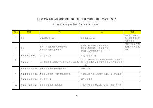
骨架应无异常变形,其线形无异常弯折。 延后初凝和微膨胀的性能 规定。且任一对称点相对高差不得有超过表中数值 2 倍且反向的偏差。 ≤ 0.1t,且 ≤ 2 删除此句
5
66 66 66 66 66 66 66 66 66
续表 8.8.6-1 项次 9 续表 8.8.6-1 注 表 8.8.6-2 项次 3 表 8.8.6-2 项次 4 表 8.8.6-2 项次 5 表 8.8.6-2 项次 7 表 8.8.6-2 注 表 8.8.6-3 项次 5 倒1行 第3行 第 11、12 行 表 8.8.7-1 项次 2 表 8.8.7-1 项次 4 表 8.8.7-2
① 上下路床填土时压实度检验标准同土方路基。 ①上下路床填土时压实度检验标准同土方路基。 ② 土石混填路基压实度可根据实际可能进行检 验。 查施工记录并结合重型动力触探 查施工记录并结合 0.2%成桩取芯检查 不小于设计值 查施工记录并结合取芯检查 查施工记录 查施工记录并结合取芯检查 0.2%,且不少于 3 根 满足设计要求 查施工记录并结合取芯检查 0.2%,且不少于 3 根
删除此句
63
表 8.8.3-1 项次 4
63
表 8.8.3-2 项次 5
������ ≤ 60m ������ > 60������
64 64 64 64 65 65 65 65 66
第7行 第9行 第 12、13 行 表 8.8.5-2 项次 3 表 8.8.5-3 项次 4 第2行 第9行 倒 2、1 行 续表 8.8.6-1 项次 7
1
表 4.4.2-5 项次 4△ 表 4.4.2-5 项次 5 表 4.4.2-6 项次 1△ 14 18 第2行 第9行
考试指导从书正文内容勘误.docx

考试指导从书正文内容勘误1.P28第1题D选项改为“物体的温度升高,它的内能增加”2.P41第8题原实物图上的电阻忌改为川,原&改为忌3.P68 第28 题表格屮最高车速是36km/h;电动机的额定功率:500W,电池规格:48V/20Ah第3问广电动自行车的正常工作电流徴为“电动自行车的工作电流二参考答案第一单元声现象l.D 2.D 3.A 4.A 5.B 6.C 7.A &D 9.A 10.A 11.阻隔噪音传播到人耳12.声音能在水屮传播空气13.狗狗海豚钢琴的最低音14.响度音色音调15.较好16.信息能量17.大高1&声的反射笫二单元光现彖l.B 2.D 3.D 4.B 5.D 6.C 7.A 8.B 9.这是由于光的直线传播所形成的太阳的像正立等大虚倒立缩小实10.玄线传播反射虚像11.漫反射黑12•光的反射光的折射虚13.远近14.(提示:作出球心关于镜面的对称点,再以相同的半径作圆,作出的圆用虚线表示)15.略16.略笫三单元热现象l.A 2.B 3.B 4.A 5.C 6.D 7.C 8.D 9.D 10.液化液化液化需要放热11.液化吸热12.(1)温度现象(2)B A(3)85°C丙(4)降低杯内气压降低使杯内水的沸点降低笫四单元热和能l.D 2.C 3.B 4.B 5.C 6.C 7.A 8.C 9.D 10.热值11. 8.4x10’14°C 28 12.机械内内机械做功惯性13.化学机械14.热传递水的比热容较大高温蒸汽对壶盖做功(或内能转换为机械能)15. (1)做功(2)热传递(3)热传递16.1.84X107J4.6x107J/kg 17.2.1X107J1.05X107J50%1. C2. A3. B4.C 5 .正 电路电阻第六单元 欧姆定律l.B 2.B 3.A 4.A 5.0.9A 50Q 6.12Q 12Q 0.25A 12Q7. (1)电阻一定时,导体中的电流跟导体两端的电压成正比电压一定时,导体中的电流跟导休的电阻成反比 (2) 大于右8. (1)电压表可能与滑动变阻器并联,测虽滑动变阻器两端的电压 (2) 8.3(3)灯丝的电阻随温度升高而变人 容易(4)电路如右图,步骤:按图连接电路,断开S 测出滑动变阻器两端的电压 II — IIU"闭合s,测出总电压U 。
GB150勘误表
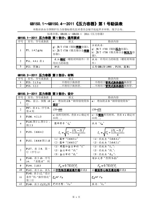
28
P232, 附录 A , A.5.2.4
θ = arctan
l0 + l11 (°) L0 + L11
,
29 30 31
32
P247, 附录 C, 表 C.1, 0~200 ≤ 200 第二行,第二列 P276, 附录 C, C.6.1 m ——垫片系数, mm; m ——垫片系数; P279, 附录 C,公式 W = 3.14 D y Wa = 3.14bDG y a G (C-89) D − Do Do Do − D2 Do 当 D ≤ 1.45时,So = 4 P283 , 附 录 C , 当 D ≤ 1.45时,So = 2 4 2 C.7.5.3.1 Do − D2 2 Do + D 当 D > 1.45时,S = Do − D2 2 Do + D2 o Do > 1.45时,So = 式 C-103 6 D + Do 当 Do D Do + D2 6 2 P292, 附录 D, D.3.1.1 P295, 附录 D, D.3.2 ......图 D.4 为全焊透 T型接头。 嵌入式接管与壳体的连接如图 D.6 所示。图 D.5 a)一般适用 于 ...... D.3.4.2对接接头连接 对接接头连接的凸缘如图 D.9 所示。 ...... S≥ δ n +3,且不大于 6mm ......图 D.4 为全截面焊透接头。 嵌入式接管与壳体的连接如图 D.6 所 示。图 D.6 a)一般适用于 ...... D.3.4.2全截面焊透接头连接 全截面焊透接头连接的凸缘如图 D.9 所示。 ...... S≥ δ n +3,且不小于 6mm
1) [σ ] / p 2)删除 1) “ T 0 ” 改为 δ” 2)图 6-14 i)修改见附图 2
ECE R92 第2次修订 第1次勘误
}Rev.1/Add.91/Amend.2/Corr.1E/ECE/324E/ECE/TRANS/50520 July 2006AGREEMENTCONCERNING THE ADOPTION OF UNIFORM TECHNICAL PRESCRIPTIONS FOR WHEELED VEHICLES, EQUIPMENT AND PARTS WHICH CAN BE FITTED AND/OR BE USED ON WHEELED VEHICLES AND THE CONDITIONS FOR RECIPROCAL RECOGNITION OF APPROVALS GRANTED ON THE BASIS OFTHESE PRESCRIPTIONS ∗/(Revision 2, including the amendments which entered into force on 16 October 1995)_________Addendum 91: Regulation No. 92Amendment 2 - Corrigendum 1Corrigendum 1 to Supplement 2 to the original version of the Regulation, subject of Depositary Notification C.N.284.2006.TREATIES-2 dated 7 April 2006UNIFORM PROVISIONS CONCERNING THE APPROVAL OF NON-ORIGINAL REPLACEMENT EXHAUST SILENCING SYSTEMS (RESS) FOR MOTORCYCLES, MOPEDS AND THREE-WHEELED VEHICLES_________UNITED NATIONS∗/ Former title of the Agreement:Agreement Concerning the Adoption of Uniform Conditions of Approval and Reciprocal Recognition of Approval for Motor Vehicle Equipment and Parts, done at Geneva on 20 March 1958.GE.06-}Rev.1/Add.91/Amend.2/Corr.1E/ECE/324E/ECE/TRANS/505Regulation No. 92page 2Paragraph 6.5., correct to read:"6.5. Evaluation of the emission of pollutants of vehicles equipped with replacement silencer systemThe vehicle referred to in paragraph 3.3.3., equipped with a replacement exhaust silencing system (RESS) of the type for which approval is requested, shall fulfil the pollution requirements according to the type approval of the vehicle. The evidence shall be documented in the test report."-----。
公路工程质量检验评定标准 第一册 土建工程(JTG F801_2017)1-1勘误表(20180501) (1)
数值 2 倍的偏差。 的规定。 满足设计要求 采用低应变反射波法或超声波法: 量规:抽查 10%桩,检查全部焊缝,每条焊缝检 3 处 超声法:满足设计要求;设计未要求时,抽查 10% 桩,每桩检查 20%焊缝,且不少于 3 条 射线法:满足设计要求;设计未要求时,抽查 10% 桩,每桩检查 2%焊缝,且不少 1 条
焊缝尺寸 D 为钢管直径,计算规定值或允许偏差时以 mm 计。 ≤ ������/3000, 且 ≤ 40 ≤ 0.2 倍壁厚,且 ≤ 2 焊缝尺寸 高强螺栓扭矩
焊缝尺寸(mm) D 为钢管直径,t 为板厚,计算规定值或允许偏差时 均以 mm 计。 允许 极值 ≤ ������/3000, 且 ≤ 40 允许偏差的 2 倍,且反向 ≤ 0.2t,且 ≤ 2 焊缝尺寸(mm) 高强螺栓扭矩(N∙m)
且任一对称点相对高差或对称接头点相对高差不得 有超过表中数值 2 倍且反向的偏差。 允许 极值 允许 极值 ������ ≤ 60m ������ > 60������ ������ ≤ 60m ������ > 60������ ≤ 20 ≤ ������/3000, 且 ≤ 40 允许偏差的 2 倍, 且反 向 ≤ 20 ≤ ������/3000, 且 ≤ 40 允许偏差的 2 倍, 且反 向
杆件在施工中,不应出现开裂或局部构件失稳。 浇筑顺序满足设计要求。 规定。且任一对称点相对高差不得有超过表中数值 2 倍且反向的偏差。 允许 极值 允许 极值 ≤ ������/3000, 且 ≤ 40 允许偏差的 2 倍,且反向 ≤ ������/3000, 且 ≤ 40 允许偏差的 2 倍,且反向
1
表 4.4.2-5 项次 4△ 表 4.4.2-5 项次 5 表 4.4.2-6 项次 1△ 14 18 第2行 第9行
ECE_R90_中文版!
[引言]E/ECE/324 } 校订(一)/附录(八十九)/校订(一)/修正(一)/修正(二)E/ECE/TRANS/505 }2005年12月09日协议考虑到目前轮式车辆都采用统一的技术标准,所以轮式车辆上安装或使用的设备及配件以及车辆与部件之间的相互识别性都必须遵从以下规定。
校订(二),包括1995年10月16日开始生效的修正条款附录(八十九):第90号规章校订(一)——修正(一)——修正(二)包括以下所有有效文件:修正(一)——生效日:1994年9月18日。
修正(一)的补充条款(一)——生效日:1995年8月14日。
修正(一)的补充条款(二)——生效日:1997年3月05日。
勘误表(一)——生效日:1997年3月05日(发行日为1997年7月03日)。
勘误表(二)——收录编号: C.N.329.1998.TREATIES-80生效日:1998年8月05日(发行日为1998年8月14日)。
修正(一)的补充条款(二)的勘误表(三)——收录编号: C.N.657.1999.TREATIES-1生效日:1999年7月20日。
修正(一)的补充条款(二)的勘误表(四)——收录编号: C.N.460.2000.TREATIES-1生效日:2000年6月30日。
修正(一)的补充条款(三)——生效日:1999年11月13日。
修正(一)的补充条款(四)——生效日:2000年12月29日。
修正(一)的补充条款(五)——生效日:2002年12月07日[R1A1-1]。
修正(一)的补充条款(六)——生效日:2005年11月09日[R9001s6-2]。
机动车辆及其挂车的备用制动器衬片总成和鼓式制动器衬片的统一标准联合国机动车辆及其挂车的备用制动器衬片总成和鼓式制动器衬片的统一标准目录1.适用范围2.名词定义3.申请认证4.批准认证5.性能规格及测试5.1.概述5.2.性能要求5.3. 车辆测试/按照第13号规章中要求开展车辆测试5.4. 速度敏感性5.5. 动力摩擦对比5.6..机械性能6.包装和标记7.修正/延期认证8.规范生产9.违规的处罚措施10.责令停产11.管理部门技术服务中心(负责开展性能品质认证测试)的名字和地址12.过渡条款附录附录1:根据第90号规章进行协商(包括:批准认证/延期认证/拒绝认证/撤消认证/责令停产)附录2:认证标志/认证日期附录3:对M1,M2和N1三类车辆的备用制动器的要求附录4:对M3,N2和N3三类车辆的备用制动器和鼓式制动器的要求附录5:对O1和O 2两类车辆的备用制动器的要求附录6:对O3和O4两类车辆的备用制动器和鼓式制动器的要求附录7:对L类车辆的备用制动器的要求附录8:测试过程中引发的摩擦干扰的鉴定机动车辆及其挂车的备用制动器衬片总成和鼓式制动器衬片的统一标准1.适用范围1.1 本章内容适用于公路机动车辆及其挂车的备用制动器衬片总成。
enc28j60勘误表

SILICON ISSUE SUMMARY
Feature — — Operating Specifications CLKOUT pin Ethernet Buffer — — — — — — — — Ethernet Buffer — — — — — Issue 1. 2. 3. 4. 5. 6. 7. 8. 9. 10. 11. 12. 13. 14. 15. 16. 17. 18. 19. Issue Summary B1 MAC registers unreliable with slow asynchronous SPI clock CLKRDY set early Industrial (-40C to +85C) temperature range unsupported CLKOUT unavailable in Power Save mode Receive buffer must start at 0000h Receive Packet Pending Interrupt Flag (PKTIF) unreliable TPIN+/- automatic polarity detection and correction unreliable RBIAS resistor value differs between silicon revisions Internal loopback in half-duplex unreliable Internal loopback in full-duplex unreliable Combined Collision and Duplex Status mode unavailable Transmit abort may stall transmit logic Received link pulses potentially cause collisions Even values in ERXRDPT may corrupt receive buffer LATECOL Status bit unreliable LED auto-polarity detection unreliable DMA checksum calculations will abort receive packets Pattern match filter allows reception of extra packets Reset command unavailable in Power Save mode X X X X X X X X X X X X X X X X X X X X X X X X Affected Revisions B4 X X X X X X X X X X X X X X X X X X X X X X X X X X X X X X X X X X X X X X X X X X X X B5 B7
ECER10中文(1)
附录 9-附件 2 .............................................................................................................................64 附录 9-附件 3 .............................................................................................................................65 附录 9-附件 4 .............................................................................................................................68
83如果管理部门对车辆制造商的检查程序不满意应采用下面的831及832条中描述的方831对从系列产品中抽取出来的车辆元件或者电子零部件esa的一致性进行验证时如果测得的值不超过622162226321和6322条中所规定的参考限值2db25以上那么可以认为产品的抗宽带电磁骚扰性能和抗窄带电磁骚扰性能符合本法规的相关要832对从系列产品中抽取出来的车辆元件或者电子零部件esa的一致性进行验证时如果当车辆处于附录6第4条所规定的状态下并且以vm为单位表示的场强值达到上面6421中所规定的参考限值的80时车辆的电气电子部件没有出现可以被驾驶员或其它道路使用者观察到的与车辆的直接控制相关的性能下降情况那么可以认为产品的抗电磁辐射性能符合本法规的相关要求
附录 6-附件 1 .............................................................................................................................39 附录 6-附件 2 .............................................................................................................................40 附录 6-附件 3 .............................................................................................................................41 附录 6-附件 4 .............................................................................................................................42 附录 6-附件 5 .............................................................................................................................43 附录 6-附件 6 .............................................................................................................................44 附录 6-附件 7 .............................................................................................................................45 附录 7 检测由电子/电气部件产生的宽带电磁骚扰的方法.......................................................46 附录 7-附件 1 电子/电气零部件检测场地...............................................................................49 附录 7-附件 2 .............................................................................................................................50 附录 8 电子/电气部件产生的窄带电磁骚扰的检测方法...........................................................52 附录 9 检测电子/电气部件抗电磁辐射性能的方法...................................................................54 附录 9-附件 1 150MM带状线路检测 .............60
信号与系统第二版教材勘误表

x(t )e jk 0t dt
ak
1 T0
T0 / 2
x(t )e jk0t dt
1 2
1 T0
x(t )e jk0t dt
97 101 106
第 16 行
ˆ(t ) x
1 2
X ( j )e
d
ˆ(t ) x
W
W
X ( j )e jt d
第七章
页数
P250 P252 P268 P272 P279
错误出处
倒数第三行开头 第六行 倒数第十行 倒数第十行 倒数第十九行
原错误
增加“解”
修正
x(2)z-2+x(3)z-3 …阶次不大于分母… …(图 2-31), (3) X(z)=…。
…x(2)z +x(3)z …(图 2-29), (3) X(z)=…;
y[n]
5 1 y[n 1] y[n 2] x[n] x[n 1] 6 6
y[n]
5 1 y[n 1] y[n 2] x[n] x[n 1] 6 6
第五章
页数 错误出处 原错误 修正
203
倒数第 6 行
叫着 x(t ) 的正交分量
叫作 x(t ) 的正交分量
H ( s) H 1 ( s) H 2 ( s)
H ( s) H 1 ( s) H 2 ( s)Байду номын сангаас
答案 6-24 中要加上:
3 h(t ) (t ) e 2t u (t ) + 8e 3t u (t ) 2 3s 2 15s 8 H (s) 2 2s 2s 12
iec 标准勘误-定义说明解析
iec 标准勘误-概述说明以及解释1.引言1.1 概述在文章的引言部分,“概述”一节起到了承上启下的作用。
概述的主要目的是简要介绍文章的主题和内容,给读者一个整体的了解。
在本文中,《IEC标准勘误》是我们要撰写的主题。
IEC(国际电工委员会)标准勘误是指在发布的标准中发现错误或不准确的地方,进行纠正和修订的过程。
标准是规范和指导各个领域的技术、产品和服务的国际性文件。
然而,由于制定标准的复杂性和繁琐性,一些错误或者不准确的内容难免会出现。
本文旨在对IEC标准勘误进行分析研究,并总结出常见的错误类型和处理方法,以提高标准的准确性和可靠性。
文章主要的结构包括引言、正文和结论三个部分。
在引言部分的概述中,我们将阐述标准勘误的重要性和意义。
针对标准作为规范文档的重要性,标准的准确性显得尤为重要。
如果标准中存在错误或者不准确的内容,将会给各个领域的技术、产品和服务带来负面影响。
因此,对标准勘误的研究和实施具有重要的现实意义。
同时,我们还会介绍标准勘误的背景和国内外相关研究现状。
通过对已有研究的梳理和分析,我们能够更好地了解标准勘误的基础和发展趋势,为我们的研究提供理论和实践的指导。
在概述部分的最后,我们将给出本文的整体结构和主要内容,以引导读者对文章的阅读。
通过对标准勘误的概述,读者能够对本文的主题和研究目的有一个清晰的认识,并为接下来的章节提供铺垫。
总之,本文的概述部分旨在介绍IEC标准勘误的背景和意义,为读者提供一个整体的概览。
通过对标准勘误的重要性和研究现状的介绍,引言部分能够引起读者的兴趣,并为后续章节的展开奠定基础。
1.2 文章结构文章结构部分的内容应包括以下内容:文章结构部分主要介绍了整篇文章的组织结构和各个章节的内容概述。
首先,本篇文章按照以下结构组织:引言、正文和结论。
引言部分是文章的开端,旨在引起读者的兴趣并提出文章的背景和问题。
具体而言,引言包含以下几个方面的内容。
1.1概述:对iec标准勘误的背景和重要性进行简单的介绍。
土工试验方法标准 勘误-解释说明
土工试验方法标准勘误-概述说明以及解释1.引言1.1 概述在土工试验方法标准中,勘误是指对已发表的标准中存在的错误或不准确之处进行修正和更正。
勘误是保证标准化工作质量和水平的重要环节,能够确保标准在实际应用中的准确性和可靠性。
对于土工试验方法标准而言,勘误的及时发现和修正对于保障工程质量和安全具有重要意义。
本文将对土工试验方法标准中存在的错误或不准确之处进行勘误,以提高相关标准的适用性和可靠性。
1.2 文章结构文章结构部分是为了让读者了解本文的整体架构和内容安排,以便更好地理解和消化文章的内容。
本文主要包括引言、正文和结论三个部分。
引言部分主要介绍了本文的背景和目的,解释了为什么需要进行勘误。
在概述部分,简要描述了土工试验方法标准存在的问题和需要纠正的错误。
在文章结构部分,则详细介绍了本文的各个部分的内容和目的。
正文部分是本文的核心内容,主要介绍了关于土工试验方法标准的勘误内容和修正建议。
通过对勘误内容1、勘误内容2和勘误内容3进行详细分析和讨论,旨在帮助读者对该标准的内容和要求有更深入的了解。
结论部分对本文的主要内容进行总结,并提出了对土工试验方法标准的影响和建议。
总结部分概括了本文的主要观点和结论,强调了修正土工试验方法标准所带来的重要性和积极影响。
在建议部分,强调了进一步加强标准制定和实施的必要性,以确保土工试验方法的准确性和可靠性。
1.3 目的本文的主要目的是对土工试验方法标准中存在的勘误进行梳理和修正,以确保土工试验方法标准的准确性和可靠性。
通过对文中涉及的勘误内容进行逐一检查和修正,可以避免在土工试验过程中出现因为标准不清晰或错误导致的误差,从而提高土工试验的准确性和可信度。
同时,通过对勘误内容的整理和分析,也可以为相关领域的研究人员提供参考和指导,促进土工试验方法标准的进一步完善和发展。
最终目的是为土工领域的研究和实践提供规范和指导,推动土工试验方法的标准化和规范化发展。
2.正文2.1 勘误内容1在土工试验方法标准的勘误内容1部分中,我们发现了一些错误或不准确的信息,需要予以更正或修正。
API 17D《水下生产系统的设计与操作-水下井口和采油树设备》第2版勘误表
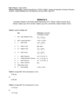
Date of Issue: August 2015Affected Publication: ANSI/API Specification 17D/ISO 13628-4, Design and Operation of Subsea Production Systems—Subsea Wellhead and Tree Equipment , Second Edition, May 2011ERRATA 6(includes changes in the Errata dated September 2011, Errata 2 dated January 2012,Errata 3 dated June 2013, Errata 4 dated July 2013, and Errata 5 dated October 2013)Table 6, replace the Key with :KeyTolerances , expressed in millimetres (inches) 1 OD, outer diameter of ring()000.150.006++−− 2ODT, outside diameter T ± 0,05, (± 0,002) 3C width of flat ()0,150,00600++ 4R 1 radius in ring See Note 1 5H a height of ring ()0,20,00800++ 6A a width of ring 7E depth of groove +0.5, -0 (+0.02, -0) 8G outside diameter of groove +0.1, -0 (+0.004, -0) 9N width of groove +0.1, -0 (+0.004, -0) 10R 2 radius in groove max. 11Break sharp corner 12 D hole diameter± 0,05, (± 0,02)Table 6, change SBX 150 for dimension E , from :5.59 mmto5.56 mmTable 6, change SBX 151 for dimension G , from :77.79 mmto77.77 mm()0,20,00800++Table 6, change SBX 153 for Outside diameter of ring from:100,94 (3.74)to100,94 (3.974)Table 8, change ‘K (Diameter of Raised Face) for 103,5 MPa (15 000 psi) rating from: 147 mm (3,985 in)to79 mm (3,110 in)Section 5.4.6.2.2 (last paragraph, 2nd sentence), change:“If a pressure-monitoring gauge and/or chart recorder is used for documentation purposes, the chart record should have a pressure settling rate not exceeding 3 % of the test pressure per 15 min or per 2 MPa (300 psi), whichever is less.”to“If a pressure-monitoring gauge and/or chart recorder is used for documentation purposes, the chart record should have a pressure settling rate not exceeding 3 % of the test pressure or 2 MPa (300 psi) per 15 min, whichever is less.”Section 5.1.7.1 (first sentence), change:“The minimum validation test procedures that shall be used to qualify product designs in accordance with Table 3 are defined in 3.5.1.7.”to“The minimum validation test procedures that shall be used to qualify product designs in accordance with Table 3 are defined as follows.”Table 11, change Groove location for Nominal size and bore 279 mm (11 in.) from:162 mm (6,370 in.)to136 mm (5,370 in.)Table 11, the proposed change Groove location for Nominal size and bore 279 mm (11 in.) from 162 mm (6,370 in.) to 136 mm (5,370 in.), issued in September 2011 as part of Errata 1, has been withdrawn. The Groove location for Nominal size and bore 279 mm (11 in.) has been reinstated to 162 mm (6,370 in.) as originally published.Section 7.10.4.2.4 (last sentence), change7.10.4.2.4to7.10.4.2.3Section 7.13.5.3 (last sentence), change reference from:7.8.4.2to7.8.3.2Section 7.14.3.2 (last sentence), change reference from:7.8.4.2to7.8.3.2Section 7.16.4.6 (list), change the list to the following: ⎯drilling riser system;⎯subsea well control package (WCP) or wireline cutter;⎯completion/workover riser or stress joint;⎯landing string (drill pipe or tubing running string);⎯ LWRP;⎯wire rope deployment system.Section 7.16.6 (last sentence), change reference from:7.8.4.2to7.8.3.2Section 7.18.1, insert after the 1st sentence:See API 17R for more information on flowline connectors. Section 7.18.4.3.b (2nd paragraph), change reference from:7.8.4.2to7.8.3.2Section 7.21.3.2.2.e, change the reference from:7.22.3.2.4to7.21.3.2.4Section 7.21.3.2.3.g , change the reference from:7.22.3.2.5to7.21.3.2.5Section 7.22.1 (2nd sentence), change the reference from:7.2.2to7.22Section 9.2.6 (last sentence), change:7.12to7.13Table G.2, change superscript in last two entries from:“b”to“a”Add footnote:a Calculated based on reduced yield strength of 655 MPa (95,000 psi)Table G.4, change superscript in last two entries from :“b”to“a”Add footnotea Calculated based on reduced yield strength of 655 MPa (95,000 psi)Section G.1.3 Equation (G.1) change the equation to read:()()()()()()()()()F P f P h D N T F f P f N ⎡⎤+π°⎡⎤⎢⎥++⎣⎦=+⎢⎥⎡⎤×⎣⎦×π−°⎢⎥⎣⎦221sec 303,175()()1410210sec 30Section G.1.3 Equation (G.2) change the equation to read:()()()()()()()()()()F P f P h D N T F f P f N ππ⎡⎤+°⎡⎤⎢⎥++⎣⎦=+⎢⎥⎡⎤⎣⎦−°⎢⎥⎣⎦1sec 300.125()()(4)(12)1212sec 30Section K.2.3.5 Equation (K.4) change the equation and list to read :2F H h C ⎛⎫=++ ⎪⎝⎭whereF is the shackle flange width as defined by item 5 in Figure K.1 F p is the pad eye design load as defined in Section K.3.1C (clearance) = 12,7 mm (0,5 in) for shackles with F p ≤ 57 827 N (13 000 lb);C (clearance) = 25,4 mm (1,0 in) for shackles with F p > 57 827 N (13 000 lb).Insert at the end of the Bibliography :[53] API RP 17R, Recommended Practice for Flowline Connectors and Jumpers。
RCC-M 2000版+2002补遗中文版勘误表
共3处
RCC-M 2000版+2002补遗中文版勘误表
Z篇 第1页
法国核电厂设计和建造规则
压水堆核岛机械设备设计和建造规则
RCC-M
2000 版+2002 补遗中文版
勘误表
第I卷 B 篇 1 级设备
B篇 1级设备
中文 英文版 版页码 页码
B/6 B2000/3 B/6 B2000/3
章节号
B2322 B2430
B/52 B3000/70 B3544.5
“在壁厚基本均匀的断面”
“在壁厚基本均匀的截面”
“由平行于阀体中心线的阀颈外表面可得 “由平行于阀体中心线的阀颈外表面可得
B/54 B3000/72 B3552.1 a) 2) 到Af”
到LA”
B/61 B3000/77 B3553.4 b) 式(11)的第1个公式中:“Sp2”
“Ke mech”
倒数第2段
B/94 B3000/145 B3683.5 b) “C3=0.1+0.03(D0/t),但不大于2.0。” “C3=1.0+0.03(D0/t),但不大于2.0。” 英文原文有误
RCC-M 2000版+2002补遗中文版勘误
B篇 第2页
B篇 1级设备
中文 英文版 版页码 页码
形式和管道相连接的大小头”
形式和管道相连接的大小头”
应力方向σt对应的应力指数一栏错误,“ νσtm+σnb,νσtm,νσtm-σnb”
“σtm+νσnb,σtm,σtm-νσnb”
RCC-M 2000版+2002补遗中文版勘误
B篇 第3页
法国核电厂设计和建造规则
压水堆核岛机械设备设计和建造规则
- 1、下载文档前请自行甄别文档内容的完整性,平台不提供额外的编辑、内容补充、找答案等附加服务。
- 2、"仅部分预览"的文档,不可在线预览部分如存在完整性等问题,可反馈申请退款(可完整预览的文档不适用该条件!)。
- 3、如文档侵犯您的权益,请联系客服反馈,我们会尽快为您处理(人工客服工作时间:9:00-18:30)。
GE.10-Agreement Concerning the Adoption of Uniform Technical Prescriptions forWheeled Vehicles, Equipment and Parts which can be Fitted and/or be Used on Wheeled Vehicles and the Conditions for Reciprocal Recognition of Approvals Granted on the Basis of these Prescriptions * (Revision 2, including the amendments which entered into force on 16 October 1995)Addendum 89: Regulation No. 90 Revision 2 – Corrigendum 1Corrigendum 1 to Revision 2 of the Regulation, subject of Depositary NotificationC.N.469.2010.TREATIES-1 dated 30 July 2010Uniform provisions concerning the approval of replacement brakelining assemblies and drum-brake linings for power-driven vehicles and their trailersUNITED NATIONS* Former title of the Agreement: Agreement Concerning the Adoption of Uniform Conditions ofApproval and Reciprocal Recognition of Approval for Motor Vehicle Equipment and Parts, done at Geneva on 20 March 1958.E /ECE/324/Rev.1/Add.89/Rev.2/Corr.1−E /ECE/TRANS/505/Rev.1/Add.89/Rev.2/Corr.127 October 2010E/ECE/324/Rev.1/Add.89/Rev.2/Corr.1E/ECE/TRANS/505/Rev.1/Add.89/Rev.2/Corr.12Paragraph 2.1., amend to read:“2.1. “Braking system” has the meaning assigned in Regulation No. 13, paragraph2.3., or Regulation No. 13-H, paragraph 2.3., or Regulation No. 78,paragraph 2.5.”Paragraph 2.7., amend to read:“2.7. “Original brake lining” means a brake lining type referenced in the vehicle type approval documentation, Regulation No. 13, Annex 2, paragraph 8.1.1.,Regulation No. 13-H, Annex 1, paragraph 7.1.2or Regulation No. 78,Annex 1, paragraph 5.4.;”Paragraph 3.2., amend to read:“3.2. An application may be submitted by the holder of (a) vehicle type approval(s) to Regulation No. 13, Regulation No. 13-H or Regulation No. 78 in respectof a replacement part conforming to the type recorded in the vehicle typeapproval(s) documentation.”Paragraph 5.1.(a), amend to read:“(a) …. prescriptions of Regulation No. 13, or Regulation No. 13-H, or Regulation No. 78;”Paragraph 5.1.1., amend to read:“5.1.1. …. type approval documentation to Regulation No. 13, Regulation No. 13-H or Regulation No. 78, are deemed to satisfy the requirements of paragraph 5.of this Regulation.”Paragraph 5.3.1.2. amend to read:“5.3.1.2. …. according to standard either ISO 6310:1981, ISO 6310:2001 or ISO 6310:2009.The compressibility …”Paragraph 5.3.2.2. amend to read:“5.3.2.2. …. according to standard either ISO 6310:1981, ISO 6310:2001 or ISO 6310:2009. Flat specimens …”Annex 3,Paragraph 1, amend to read:“1. Conformance with Regulation No. 13 or 13-HCompliance with the requirements of Regulation No. 13 or 13-H shall bedemonstrated in a vehicle test.”Paragraph 1.2., amend to read:“1.2. The braking system of the vehicle shall be tested according to the requirements for the vehicle category in question (M1, M2or N1) inRegulation No. 13, Annex 4, paragraphs 1. and 2. or Regulation No. 13-H,Annex 3, paragraphs 1. and 2. which ever is appropriate taking intoconsideration the original approval of the system. The applicablerequirements or tests are:”E/ECE/324/Add.5/Rev.4/Amend.3/Corr.2E/ECE/TRANS/505/Add.5/Rev.4/Amend.3/Corr.2Paragraph 1.2.1.1., amend to read:“1.2.1.1. Type-0 test with engine disconnected, vehicle laden, according toRegulation No. 13, Annex 4, paragraph 1.4.2. or Regulation No. 13-H,Annex 3, paragraph 1.4.2.”Paragraph 1.2.1.2., amend to read:“1.2.1.2. Type-0 test with engine connected, vehicle unladen and laden, according toRegulation No. 13, Annex 4, paragraphs 1.4.3.1. (stability test) and 1.4.3.2.(only the test with initial speed v = 0.8 v max) or Regulation No. 13-H,Annex 3, paragraphs 1.4.3.1. and 1.4.3.2.”Paragraph 1.2.1.3., amend to read:“1.2.1.3. Type-I test, according to Regulation No. 13, Annex 4, paragraph 1.5. orRegulation No. 13-H, Annex 3, paragraph 1.5.”Paragraph 1.2.2.1., amend to read:“1.2.2.1. Type-0 test with engine disconnected, vehicle laden, according toRegulation No. 13, Annex 4, paragraph 2.2. or Regulation No. 13-H,Annex 3, paragraph 2.2. (this test may be omitted in cases where it is obviousthat the requirements are met, e.g. diagonal split braking system).”Paragraph 1.2.3.1., amend to read:“1.2.3.1. Parking brake test at 18 per cent gradient, vehicle laden, according toRegulation No. 13, Annex 4, paragraph 2.3.1. or parking brake test at 20 percent gradient, vehicle laden, Regulation No. 13-H, Annex 3, paragraph2.3.1.”Paragraph 1.3., amend to read:“1.3. The vehicle must satisfy all the relevant requirements stated in RegulationNo. 13, Annex 4, paragraph 2 or Regulation No. 13-H, Annex 3, paragraph 2for that category of vehicle.”Annex 8,Paragraph 1., amend to read:“1. Compliance with Regulation No. 13 or 13-HCompliance with the requirements of Regulation No. 13 or 13-H shall bedemonstrated in a vehicle test.”Paragraph 1.1., amend to read:“1.1. Vehicle testA vehicle which is representative of the type(s) for which the replacementbrake lining assembly approval is required shall be equipped with thereplacement brake lining assemblies of the type for which approval isrequested and instrumented for brake testing as required by RegulationNo. 13 or Regulation No. 13-H whichever is appropriate. The vehicle shallbe fully laden. Brake linings submitted for test shall be fitted to the relevantbrakes and, shall not be burnished.”3E/ECE/324/Rev.1/Add.89/Rev.2/Corr.1E/ECE/TRANS/505/Rev.1/Add.89/Rev.2/Corr.14Paragraph 1.2., amend to read:“1.2. The parking braking system of the vehicle shall be tested according to all relevant requirements in Regulation No. 13, Annex 4, paragraph 2.3 orRegulation No. 13-H, Annex 3, paragraph 2.3., whichever is appropriatetaking into consideration the original approval of the system.”。