Hw6_Sol
大学英语精读第5册和第6册课文全文翻译

教说番一
nomreS fo dniK A
译翻文课文全册Βιβλιοθήκη 6 第和册 5 第读精语英学大到 不 得 却候 时 的及 得来 还 在“ � 吗由 自 有子 孩 个 这。养培或练训到受能可不他�特扎莫的没埋被 个一成写描被�市城某非北于逛闲常经�年少伯 里帕休克埃?圣家作国法在 �由自的峰顶就成人个 到达是它。险危的它失丢有们我�石基之由自种 四述上是也�由自种五第着在存还时同此与 。着斗奋而由自些这为地各 界世和土本国美在然仍民移老新的列行其入加来 后及以代后的者荒拓些这今如。由自的仰信教宗 及以论言、惧恐除消�穷贫离脱�是们它。惜珍 外格然仍天今们我由自。斯茅列普和敦斯姆詹到 来�洋重涉远前年多百三在�由自的在存不已国 祖的己自们他在找寻了为者荒拓期早群小一 拉阿的俐伶明聪得长却衫烂衣破个一�里品作的
taht dias netfo si tI .taht od ot yenom eht ro emit eht evah stneduts weF .meht fo sdnah s'eno gnihsaw ot stnuoma hcihw ,yrtnuoc gnikaeps-hsilgnE na ni sraey eerht ro owt dneps dluohs stneduts taht tseggus nac enO .noitulos eht gnidivorp naht reisae si melborp eht gninifeD .unem tsav a morf yad nevig a no tae ot ekil tsom dluow uoy hsid eht esoohc ot naht dnik yna fo doof teg ot reisae hcum si tI .ksat tluciffid erom a semoceb thguat eb dluohs tahw gnitceles ,weiv fo tniop s'rehcaet eht morf ,nosaer emas eht roF .noitacilppa fo dleif etaidemmi ssel a evah os dna dootsrednu fleseno gnikam ot lativ sa ton era egaugnal a ni sretnuocne eno serutcurts xelpmoc erom eht taht noitingocer eht si gnicneirepxe era srehcaet dna stneduts htob tahW .eurt ton si siht esruoc fO ".wonk I ssel eht ,nrael I erom ehT" :htiw eseht retnuoc ot denilcni leef thgim stneduts siH ".ti yas uoy taht yaw eht s'tI .yas uoy tahw t'nac uoy tub retaw ot esroh a dael nac uoY" :sa hcus seugaelloc sih ot sbrevorp gnitouq ni egufer ekat yam ,elbacilpxeni eht nialpxe ot gniyrt ot decuder yltneuqerf ,trap sih rof ,rehcaet ehT .tsrif ta meht reffo ot elba saw eh ecnadiug tnedifnoc emas eht meht evig ot rehcaet eht rof yllufepoh tiaw llits srehto elihw ,tsugsid ni pu evig emos taht gnisirprus yldrah si ti secnatsmucric hcus nI .noitacided dna emit nevig ,evorpmi ot niatrec si hsilgnE rieht taht dna ycneulf sdrawot ssergorp gnikam llits era yeht taht meht ecnivnoc ot drah si tI .stxetnoc tnereffid ni sgninaem tnereffid htiw sesarhp detpecca dna déhcilc ,smoidi fo yteirav gniredliweb a fo tsisnoc ot sraeppa won wenk yeht thguoht yeht egaugnal eht esuaceb gnilggurts meht sees eH .skoobtxet cisab fo epocs eht edistuo sllaf hcihw egasu dna yralubacov hsilgnE fo aera dehcuotnu tsav eht htiw detnorfnoc nehw etatiseh ,ecitcarp otni thguat neeb dah yeht gnihtyreve gnittup ni dedeeccus yeht esuaceb ,hcaet ot ysae erew ohw stneduts taht sdnif eH .stluser suoivbo ssel ecudorp ot raeppa stroffe sih nehw detartsurf semoceb ,oot ,rehcaet eht taht tuo tniop ot noitalosnoc hcum mees ton yam tI .os od ot raeppa ton seod relpmis emoceb ot thguo hcihw ssecorp a taht revocsid ot detnioppasid dna desirprus yllarutan era stnedutS .dootsrednu neeb evah egaugnal eht fo snrettap dna serutcurts cisab eht ecno tluciffid ylgnisaercni emoceb ot smees hsilgnE gninrael yhw snosaer eht etaicerppa ot stneduts rof naht srehcaet rof reisae ylbaborp si tI
北京联盛德微电子有限责任公司W601芯片规格书说明书

W601芯片规格书V1.0.4北京联盛德微电子有限责任公司 (Winner Micro)地址:北京市海淀区阜成路67号银都大厦18层电话:+86-10-62161900网址:文档历史目录1特征 (1)2概述 (4)3芯片特点 (4)4芯片结构 (4)5功能描述 (4)5.1SDIO设备控制器 (4)5.2高速SPI设备控制器 (5)5.3DMA控制器 (5)5.4时钟与复位 (5)5.5内存管理器 (5)5.6数字基带 (5)5.7MAC控制器 (6)5.8安全系统 (6)5.9FLASH控制器 (6)5.10RSA加密模块 (7)5.11通用硬件加密模块 (7)5.12I2C控制器 (7)5.13SAR ADC (7)5.14主/从SPI控制器 (7)5.15UART控制器 (8)5.16GPIO控制器 (8)5.17定时器 (8)5.18看门狗控制器 (8)5.19射频配置器 (8)5.20射频收发器 (8)5.21PWM控制器 (9)5.22I²S控制器 (9)5.237816/UART控制器 (9)5.24LCD控制器 (10)6管脚定义 (11)7电气特性 (14)7.1极限参数 (14)7.2射频功耗参数 (14)7.3Wi-Fi射频 (14)8封装信息 (16)1特征⚫芯片外观➢QFN68封装,7mm x 7mm⚫芯片集成度◼MCU 特性➢集成32位嵌入式Cortex-M3处理器,工作频率80MHz,内置1MB Flash,288KB RAM;➢集成3路UART 高速接口,波特率范围1200bps~2Mbps;➢集成8路10比特差分 ADC;➢集成1个SPI主从控制器,支持速率20MHz➢集成1个高速SPI从设备接口,支持最高50MHz;➢集成1个SDIO控制器,支持最高50MHz;➢集成1个I2C控制器,支持100/400Kbps 速率;➢集成GPIO控制器,支持48位可控GPIO;➢集成5路PWM接口;➢集成I2S控制器;➢集成7816接口,支持EVM2000规范,兼容串口功能;➢集成LCD控制器,最高支持4x20/8x16接口,支持2.7V~3.6V电压输出。
欧圣 手持控制器 HBA 使用说明书

These operating instructions are valid only in connection with the data sheet of the rele-vant hand-held pendant station HBA and with the operating instructions of the relevant HBA handwheel!Correct useMachine installations in manual mode can be operated with hand-held pendant stations.Handwheels are used as part of an overall higher-level control system.Their use, installation and operation are permissible only in conformity with these operating instructions.Incorrect useHand-held pendant stations on their own must not be used as safety components for avoiding hazar-dous states in a machine installation.General functionHand-held pendant stations make it possible to operate a machine installation, for instance, in manual mode.Function of individual componentsThe hand-held pendant station may consist of the following components: HandwheelEMERGENCY-STOP device Enabling switches Selector switches PushbuttonsHBA handwheelThe electronic HBA handwheel is a universal pulse generator for manual shaft positioning.An output of 100 or 25 square-wave pulses per revolution is available. A second phase-shifted output allows the connected controller to detect the direction of movement.The pulses are evaluated in the controller.For details, please see the Electronic HBA handwheel operating instructions.EMERGENCY-STOP deviceThe EMERGENCY-STOP device is designed to be mani-pulation-proof in accordance with IEC 60947-5-1/EN ISO 13850.Enab ling switches, selector switches,pushbuttonsThese components are used to transfer additional information to the higher-level machine controller.AssemblyHand-held pendant stations are not used exclusively at a single site. The stations can be stored using a mounting magnet on the rear of the device or a holder.Electrical connectionAlways shield connecting leads.Ground the shield at the open end of the lead at a central grounding point, e.g. in the distribution board or in the control cabinet, over a large sur-face, with low resistance and with low inductance. In the case of leads with plug connectors, ensure that the connection type is EMC-compliant.Original connecting leads must not be shortened. G iven an extension or other modification to the connection cable, the operator must ensure that the valid EMC protection requirements are observed. Do not install connecting leads in the immediate vicinity of interference sources.Authorization according to:Operation with UL-class 2 power supply only.Connection leads of hand-held pendant stations in-stalled at the application site must be separated from all movable and permanently installed leads and non-insulated active parts of other installation parts which operate with a voltage of over 150 V, in such a way that a constant clearance of 50.8 mm is observed. This does not apply if the movable leads are equipped with suitable insulation materials which possess an identical voltage stability to the other relevant installation parts or higher.Service and inspectionEUCHNER handwheels require no maintenance.Handwheels may only be repaired by the manufac-turer.To clean the handwheels, only use solvent-free cle-aning agents and a soft cloth.Disclaimer of liabilityThe company is unable to accept liability in the following cases:if instructions are not followedif the safety instructions are not followedif the units are electrically connected by unautho-rised personnelif any external intervention occursDo not open hand-held pendant stations!Do not throw or drop the hand-held pendant stati-ons!LISTEDPOW. CONV. EQ.82HAEUCHNER GmbH + Co. KG Kohlhammerstra ße 16D-70771 Leinfelden-Echterdingen Tel. +49/711/75 97-0Fax +49/711/75 33 16www.euchner.de ***************S u b j e c t t o t e c h n i c a l m o d i f i c a t i o n s ; n o r e s p o n s i b i l i t y i s a c c e p t e d f o r t h e a c c u r a c y o f t h i s i n f o r m a t i o n .© E U C H N E R G m b H + C o . K G072850-05-02/12 (T r a n s l a t i o n o f t h e o r i g i n a l o p e r a t i n g i n s t r u c t i o n s )ColourGrey RAL 7040/Black RAL 9004Weight1.3 kg Operating temperature 0 °C ... +50 °C Storage temperature -20 °C ... +50 °CHumidity, max.80 %(condensation not permissible)Degree of protection to the frontIn accordance with EN60529 / IEC529IP 65In accordance with NEMA 250-12Resistance to vibrationVibrations (3 axes)DIN/IEC 68-2-6Shock (3 axes)DIN/IEC 68-2-27EMC protection requirements EN 61000-6-2in accordance with CEEN 61000-6-4Switching elements Max. 2 NC contactsUtilization categoryDC-13according to IEC 60947-5-1U e =24 V / I e= 3 A Resistive loadAC 30 V / 0.4 ADC 30 V / 0.1 A Switching voltage, max.30 V DC Switching current, max.0.1 A Switching capacity, max.1 VA see wiring diagramSwitching voltage, max.25 V Switching capacity, max.0,2 VAwww.euchner.deTechnical data, handwheelSee relevant operating instructions for HBA hand-wheel.AccessoriesSee EUCHNER catalogue for hand-held pendant stations or www.euchner.de.。
W25Q128JVSIQ规格书_W25Q128JVSIQ中文资料_W25Q128JVSIQ Datasheet

Publication Release Date: May 02, 2017Revision D3V 128M-BITSERIAL FLASH MEMORY WITH DUAL/QUAD SPI- 1 -Table of Contents1. GENERAL DESCRIPTIONS ............................................................................................................. 42. FEATURES ....................................................................................................................................... 43.PACKAGE TYPES AND PIN CONFIGURATIONS ........................................................................... 5 3.1 Pin Configuration SOIC 208-mil ........................................................................................... 5 3.2 Pad Configuration WSON 6x5-mm/ 8x6-mm ....................................................................... 5 3.3 Pin Description SOIC 208-mil, WSON 6x5-mm / 8x6-mm ................................................... 5 3.4 Pin Configuration SOIC 300-mil ........................................................................................... 6 3.5 Pin Description SOIC 300-mil ............................................................................................... 6 3.6 Ball Configuration TFBGA 8x6-mm (5x5 or 6x4 Ball Array) ................................................. 7 3.7Ball Description TFBGA 8x6-mm ......................................................................................... 7 4. PIN DESCRIPTIONS ........................................................................................................................ 8 4.1 Chip Select (/CS) .................................................................................................................. 8 4.2 Serial Data Input, Output and IOs (DI, DO and IO0, IO1, IO2, IO3) ..................................... 8 4.3 Write Protect (/WP) .............................................................................................................. 8 4.4 HOLD (/HOLD) ..................................................................................................................... 8 4.5 Serial Clock (CLK) ................................................................................................................ 8 4.6Reset (/RESET) (8)5. BLOCK DIAGRAM ............................................................................................................................ 96.FUNCTIONAL DESCRIPTIONS ..................................................................................................... 10 6.1 Standard SPI Instructions ................................................................................................... 10 6.2 Dual SPI Instructions .......................................................................................................... 10 6.3 Quad SPI Instructions ......................................................................................................... 10 6.4 Software Reset & Hardware /RESET pin ........................................................................... 10 6.5Write Protection (11)6.5.1 Write Protect Features (11)7. STATUS AND CONFIGURATION REGISTERS ............................................................................ 12 7.1Status Registers (12)7.1.1 Erase/Write In Progress (BUSY) – Status Only ................................................................ 12 7.1.2 Write Enable Latch (WEL) – Status Only .......................................................................... 12 7.1.3 Block Protect Bits (BP2, BP1, BP0) – Volatile/Non-Volatile Writable ................................ 12 7.1.4 Top/Bottom Block Protect (TB) – Volatile/Non-Volatile Writable ....................................... 13 7.1.5 Sector/Block Protect Bit (SEC) – Volatile/Non-Volatile Writable ....................................... 13 7.1.6 Complement Protect (CMP) – Volatile/Non-Volatile Writable ............................................ 13 7.1.1 Status Register Protect (SRP, SRL) – Volatile/Non-Volatile Writable ............................... 14 7.1.2 Erase/Program Suspend Status (SUS) – Status Only . (15)Publication Release Date: May 02, 2017- 2 - Revision D7.1.3 Security Register Lock Bits (LB3, LB2, LB1) – Volatile/Non-Volatile OTP Writable .......... 15 7.1.4 Quad Enable (QE) – Volatile/Non-Volatile Writable .......................................................... 15 7.1.5 Write Protect Selection (WPS) – Volatile/Non-Volatile Writable ....................................... 16 7.1.6 Output Driver Strength (DRV1, DRV0) – Volatile/Non-Volatile Writable ........................... 16 7.1.7 Reserved Bits – Non Functional ........................................................................................ 16 7.1.8 W25Q128JV Status Register Memory Protection (WPS = 0, CMP = 0) ............................... 17 7.1.9 W25Q128JV Status Register Memory Protection (WPS = 0, CMP = 1) ............................... 18 7.1.10 W25Q128JV Individual Block Memory Protection (WPS=1) . (19)8. INSTRUCTIONS ............................................................................................................................. 20 8.1Device ID and Instruction Set Tables (20)8.1.1 Manufacturer and Device Identification ................................................................................ 20 8.1.2 Instruction Set Table 1 (Standard SPI Instructions)(1)........................................................... 21 8.1.3 Instruction Set Table 2 (Dual/Quad SPI Instructions) ........................................................... 22 Notes: (22)8.2 Instruction Descriptions (23)8.2.1 Write Enable (06h) ............................................................................................................... 23 8.2.2 Write Enable for Volatile Status Register (50h) .................................................................... 23 8.2.3 Write Disable (04h) ............................................................................................................... 24 8.2.4 Read Status Register-1 (05h), Status Register-2 (35h) & Status Register-3 (15h) .............. 24 8.2.5 Write Status Register-1 (01h), Status Register-2 (31h) & Status Register-3 (11h) .............. 25 8.2.6 Read Data (03h) ................................................................................................................... 27 8.2.7 Fast Read (0Bh) ................................................................................................................... 28 8.2.8 Fast Read Dual Output (3Bh) ............................................................................................... 29 8.2.9 Fast Read Quad Output (6Bh) .............................................................................................. 30 8.2.10 Fast Read Dual I/O (BBh) ................................................................................................... 31 8.2.11 Fast Read Quad I/O (EBh) ................................................................................................. 32 8.2.12 Set Burst with Wrap (77h) .................................................................................................. 34 8.2.13 Page Program (02h) ........................................................................................................... 35 8.2.14 Quad Input Page Program (32h) ........................................................................................ 36 8.2.15 Sector Erase (20h) ............................................................................................................. 37 8.2.16 32KB Block Erase (52h) ..................................................................................................... 38 8.2.17 64KB Block Erase (D8h) ..................................................................................................... 39 8.2.18 Chip Erase (C7h / 60h) ....................................................................................................... 40 8.2.19 Erase / Program Suspend (75h) ......................................................................................... 41 8.2.20 Erase / Program Resume (7Ah) ......................................................................................... 42 8.2.21 Power-down (B9h) .............................................................................................................. 43 8.2.22 Release Power-down / Device ID (ABh) ............................................................................. 44 8.2.23 Read Manufacturer / Device ID (90h) ................................................................................. 45 8.2.24 Read Manufacturer / Device ID Dual I/O (92h) ................................................................... 46 8.2.25 Read Manufacturer / Device ID Quad I/O (94h) ................................................................. 47 8.2.26 Read Unique ID Number (4Bh). (48)- 3 -8.2.27 Read JEDEC ID (9Fh) ........................................................................................................ 49 8.2.28 Read SFDP Register (5Ah) ................................................................................................ 50 8.2.29 Erase Security Registers (44h) ........................................................................................... 51 8.2.30 Program Security Registers (42h) ...................................................................................... 52 8.2.31 Read Security Registers (48h) ........................................................................................... 53 8.2.32 Individual Block/Sector Lock (36h) ..................................................................................... 54 8.2.33 Individual Block/Sector Unlock (39h) .................................................................................. 55 8.2.34 Read Block/Sector Lock (3Dh) ........................................................................................... 56 8.2.35 Global Block/Sector Lock (7Eh) .......................................................................................... 57 8.2.36 Global Block/Sector Unlock (98h) ....................................................................................... 57 8.2.37 Enable Reset (66h) and Reset Device (99h) . (58)9.ELECTRICAL CHARACTERISTICS (59)9.1 Absolute Maximum Ratings (1) ............................................................................................ 59 9.2 Operating Ranges............................................................................................................... 59 9.3 Power-Up Power-Down Timing and Requirements ............................................................ 60 9.4 DC Electrical Characteristics- ............................................................................................. 61 9.5 AC Measurement Conditions .............................................................................................. 62 9.6 AC Electrical Characteristics (6) ........................................................................................... 63 9.7 Serial Output Timing ........................................................................................................... 65 9.8 Serial Input Timing .............................................................................................................. 65 9.9/WP Timing ......................................................................................................................... 65 10. PACKAGE SPECIFICATIONS ........................................................................................................ 66 10.1 8-Pin SOIC 208-mil (Package Code S) .............................................................................. 66 10.2 16-Pin SOIC 300-mil (Package Code F) ............................................................................ 67 10.3 8-Pad WSON 6x5-mm (Package Code P) ......................................................................... 68 10.4 8-Pad WSON 8x6-mm (Package Code E) ......................................................................... 69 10.5 24-Ball TFBGA 8x6-mm (Package Code B, 5x5-1 ball array) ............................................ 70 10.624-Ball TFBGA 8x6-mm (Package Code C, 6x4 ball array) ............................................... 71 11. ORDERING INFORMATION .......................................................................................................... 72 11.1Valid Part Numbers and Top Side Marking (73)12. REVISION HISTORY (74)Publication Release Date: May 02, 2017- 4 - Revision D1. GENERAL DESCRIPTIONSThe W25Q128JV (128M-bit) Serial Flash memory provides a storage solution for systems with limited space, pins and power. The 25Q series offers flexibility and performance well beyond ordinary Serial Flash devices. They are ideal for code shadowing to RAM, executing code directly from Dual/Quad SPI (XIP) and storing voice, text and data. The device operates on a single 2.7V to 3.6V power supply with current consumption as low as 1µA for power-down. All devices are offered in space-saving packages.The W25Q128JV array is organized into 65,536 programmable pages of 256-bytes each. Up to 256 bytes can be programmed at a time. Pages can be erased in groups of 16 (4KB sector erase), groups of 128 (32KB block erase), groups of 256 (64KB block erase) or the entire chip (chip erase). The W25Q128JV has 4,096 erasable sectors and 256 erasable blocks respectively. The small 4KB sectors allow for greater flexibility in applications that require data and parameter storage. (See Figure 2.)The W25Q128JV supports the standard Serial Peripheral Interface (SPI), Dual/Quad I/O SPI: Serial Clock, Chip Select, Serial Data I/O0 (DI), I/O1 (DO), I/O2 and I/O3. SPI clock frequencies of W25Q128JV of up to 133MHz are supported allowing equivalent clock rates of 266MHz (133MHz x 2) for Dual I/O and 532MHz (133MHz x 4) for Quad I/O when using the Fast Read Dual/Quad I/O. These transfer rates can outperform standard Asynchronous 8 and 16-bit Parallel Flash memories.Additionally, the device supports JEDEC standard manufacturer and device ID and SFDP, and a 64-bit Unique Serial Number and three 256-bytes Security Registers.2. FEATURES∙ New Family of SpiFlash Memories – W25Q128JV: 128M-bit / 16M-byte – Standard SPI: CLK, /CS, DI, DO – Dual SPI: CLK, /CS, IO 0, IO 1 – Quad SPI: CLK, /CS, IO 0, IO 1, IO 2, IO 3 – Software & Hardware Reset (1) ∙ Highest Performance Serial Flash – 133MHz Single, Dual/Quad SPI clocks – 266/532MHz equivalent Dual/Quad SPI – 66MB/S continuous data transfer rate – Min. 100K Program-Erase cycles per sector – More than 20-year data retention ∙ Efficient “Continuous Read”– Continuous Read with 8/16/32/64-Byte Wrap– As few as 8 clocks to address memory– Allows true XIP (execute in place) operation ∙ Low Power, Wide Temperature Range– Single 2.7 to 3.6V supply– <1µA Power-down (typ.)– -40°C to +85°C operating range∙ Flexible Architecture with 4KB sectors – Uniform Sector/Block Erase (4K/32K/64K-Byte) – Program 1 to 256 byte per programmable page – Erase/Program Suspend & Resume ∙ Advanced Security Features – Software and Hardware Write-Protect – Power Supply Lock-Down – Special OTP protection – Top/Bottom, Complement array protection – Individual Block/Sector array protection – 64-Bit Unique ID for each device – Discoverable Parameters (SFDP) Register– 3X256-Bytes Security Registers with OTP locks – Volatile & Non-volatile Status Register Bits ∙ Space Efficient Packaging – 8-pin SOIC 208-mil– 16-pin SOIC 300-mil (additional /RESET pin) – 8-pad WSON 6x5-mm / 8x6-mm – 24-ball TFBGA 8x6-mm (6x4/5x5 ball array) – Contact Winbond for KGD and other options Note: 1. Hardware /RESET pin is only available on TFBGA or SOIC16 packages- 5 -3. PACKAGE TYPES AND PIN CONFIGURATIONS3.1 Pin Configuration SOIC 208-milFigure 1a. W25Q128JV Pin Assignments, 8-pin SOIC 208-mil (Package Code S)3.2 Pad Configuration WSON 6x5-mm/ 8x6-mmFigure 1b. W25Q128JV Pad Assignments, 8-pad WSON 6x5-mm/ 8x6-mm (Package Code P/E)3.3 Pin Description SOIC 208-mil, WSON 6x5-mm / 8x6-mmNotes:1. IO0 and IO1 are used for Standard and Dual SPI instructions2.IO0 – IO3 are used for Quad SPI instructions, /HOLD (or /RESET) function is only available for Standard/Dual SPI.Publication Release Date: May 02, 2017- 6 - Revision D3.4 Pin Configuration SOIC 300-milFigure 1c. W25Q128JV Pin Assignments, 16-pin SOIC 300-mil (Package Code F)3.5 Pin Description SOIC 300-milNotes:1. IO0 and IO1 are used for Standard and Dual SPI instructions.2. IO0 – IO3 are used for Quad SPI instructions, /HOLD (or /RESET) function is only available for Standard/Dual SPI.3. The /RESET pin is a dedicated hardware reset pin regardless of device settings or operation states. If the hardware reset function is not used, this pin can be left floating or connected to VCC in the system.3.6Ball Configuration TFBGA 8x6-mm (5x5 or 6x4 Ball Array)Figure 1d. W25Q128JV Ball Assignments, 24-ball TFBGA 8x6-mm (Package Code B/C)3.7Ball Description TFBGA 8x6-mmNotes:1.IO0 and IO1 are used for Standard and Dual SPI instructions2.IO0 – IO3 are used for Quad SPI instructions, /HOLD (or /RESET) function is only available for Standard/Dual SPI.3. The /RESET pin is a dedicated hardware reset pin regardless of device settings or operation states.If the hardware reset function is not used, this pin can be left floating or connected to VCC in the system- 7 -Publication Release Date: May 02, 2017- 8 - Revision D4. PIN DESCRIPTIONS4.1 Chip Select (/CS)The SPI Chip Select (/CS) pin enables and disables device operation. When /CS is high the device is deselected and the Serial Data Output (DO, or IO0, IO1, IO2, IO3) pins are at high impedance. When deselected, the devices power consumption will be at standby levels unless an internal erase, program or write status register cycle is in progress. When /CS is brought low the device will be selected, power consumption will increase to active levels and instructions can be written to and data read from the device. After power-up, /CS must transition from high to low before a new instruction will be accepted. The /CS input must track the VCC supply level at power-up and power-down (see “Write Protection” and Figure 58). If needed a pull-up resister on the /CS pin can be used to accomplish this.4.2 Serial Data Input, Output and IOs (DI, DO and IO0, IO1, IO2, IO3)The W25Q128JV supports standard SPI, Dual SPI and Quad SPI operation. Standard SPI instructions use the unidirectional DI (input) pin to serially write instructions, addresses or data to the device on the rising edge of the Serial Clock (CLK) input pin. Standard SPI also uses the unidirectional DO (output) to read data or status from the device on the falling edge of CLK.Dual and Quad SPI instructions use the bidirectional IO pins to serially write instructions, addresses or data to the device on the rising edge of CLK and read data or status from the device on the falling edge of CLK. Quad SPI instructions require the non-volatile Quad Enable bit (QE) in Status Register-2 to be set. When QE=1, the /WP pin becomes IO2 and the /HOLD pin becomes IO3.4.3 Write Protect (/WP)The Write Protect (/WP) pin can be used to prevent the Status Register from being written. Used in conjunction with the Status Register’s Block Protect (CMP, SEC, TB, BP2, BP1 and BP0) bits and Status Register Protect (SRP) bits, a portion as small as a 4KB sector or the entire memory array can be hardware protected. The /WP pin is active low.4.4 HOLD (/HOLD)The /HOLD pin allows the device to be paused while it is actively selected. When /HOLD is brought low, while /CS is low, the DO pin will be at high impedance and signals on the DI and CLK pins will be ignored (don’t care). When /HOLD is brought high, device operation can resume. The /HOLD function can be useful when multiple devices are sharing the same SPI signals. The /HOLD pin is active low. When the QE bit of Status Register-2 is set for Quad I/O, the /HOLD pin function is not available since this pin is used for IO3. See Figure 1a-c for the pin configuration of Quad I/O operation.4.5 Serial Clock (CLK)The SPI Serial Clock Input (CLK) pin provides the timing for serial input and output operations. ("See SPI Operations")4.6 Reset (/RESET)A dedicated hardware /RESET pin is available on SOIC-16 and TFBGA packages. When it’s driven low for a minimum period of ~1µS, this device will terminate any external or internal operations and return to its power-on state.Note: Hardware /RESET pin is available on SOIC-16 or TFBGA; please contact Winbond for this package.- 9 -5. BLOCK DIAGRAMFigure 2. W25Q128JV Serial Flash Memory Block Diagram6.FUNCTIONAL DESCRIPTIONS6.1Standard SPI InstructionsThe W25Q128JV is accessed through an SPI compatible bus consisting of four signals: Serial Clock (CLK), Chip Select (/CS), Serial Data Input (DI) and Serial Data Output (DO). Standard SPI instructions use the DI input pin to serially write instructions, addresses or data to the device on the rising edge of CLK. The DO output pin is used to read data or status from the device on the falling edge of CLK.SPI bus operation Mode 0 (0,0) and 3 (1,1) are supported. The primary difference between Mode 0 and Mode 3 concerns the normal state of the CLK signal when the SPI bus master is in standby and data is not being transferred to the Serial Flash. For Mode 0, the CLK signal is normally low on the falling and rising edges of /CS. For Mode 3, the CLK signal is normally high on the falling and rising edges of /CS.6.2Dual SPI InstructionsThe W25Q128JV supports Dual SPI operation when using instructions such as “Fast Read Dual Output (3Bh)” and “Fast Read Dual I/O (BBh)”. These instructions allow data to be transferred to or from the device at two to three times the rate of ordinary Serial Flash devices. The Dual SPI Read instructions are ideal for quickly downloading code to RAM upon power-up (code-shadowing) or for executing non-speed-critical code directly from the SPI bus (XIP). When using Dual SPI instructions, the DI and DO pins become bidirectional I/O pins: IO0 and IO1.6.3Quad SPI InstructionsThe W25Q128JV supports Quad SPI operation when using instructions such as “Fast Read Quad Output (6Bh)”,and “Fast Read Quad I/O (EBh). These instructions allow data to be transferred to or from the device four to six times the rate of ordinary Serial Flash. When using Quad SPI instructions, the DI and DO pins become bidirectional IO0 and IO1, with the additional I/O pins: IO2, IO3.6.4Software Reset & Hardware /RESET pinThe W25Q128JV can be reset to the initial power-on state by a software Reset sequence. This sequence must include two consecutive instructions: Enable Reset (66h) & Reset (99h). If the instruction sequence is successfully accepted, the device will take approximately 30µS (t RST)to reset. No instruction will be accepted during the reset period. For the SOIC-16 and TFBGA packages, W25Q128JV provides a dedicated hardware /RESET pin. Drive the /RESET pin low for a minimum period of ~1µS (tRESET*) will interrupt any on-going external/internal operations and reset the device to its initial power-on state. Hardware /RESET pin has higher priority than other SPI input signals (/CS, CLK, IOs).Note:1.Hardware /RESET pin is available on SOIC-16 or TFBGA; please contact Winbond for his package.2.While a faster /RESET pulse (as short as a few hundred nanoseconds) will often reset the device, a 1us minimum isrecommended to ensure reliable operation.3.There is an internal pull-up resistor for the dedicated /RESET pin on the SOIC-16 and TFBGA-24 package. If the reset functionis not needed, this pin can be left floating in the system.6.5Write ProtectionApplications that use non-volatile memory must take into consideration the possibility of noise and other adverse system conditions that may compromise data integrity. To address this concern, the W25Q128JV provides several means to protect the data from inadvertent writes.6.5.1Write Protect Features∙Device resets when VCC is below threshold∙Time delay write disable after Power-up∙Write enable/disable instructions and automatic write disable after erase or program∙Software and Hardware (/WP pin) write protection using Status Registers∙Additional Individual Block/Sector Locks for array protection∙Write Protection using Power-down instruction∙Lock Down write protection for Status Register until the next power-up∙One Time Program (OTP) write protection for array and Security Registers using Status Register** Note:This feature is available upon special order. Please contact Winbond for details.Upon power-up or at power-down, the W25Q128JV will maintain a reset condition while VCC is below the threshold value of V WI, (See Power-up Timing and Voltage Levels and Figure 43). While reset, all operations are disabled and no instructions are recognized. During power-up and after the VCC voltage exceeds V WI, all program and erase related instructions are further disabled for a time delay of t PUW. This includes the Write Enable, Page Program, Sector Erase, Block Erase, Chip Erase and the Write Status Register instructions. Note that the chip select pin (/CS) must track the VCC supply level at power-up until the VCC-min level and t VSL time delay is reached, and it must also track the VCC supply level at power-down to prevent adverse command sequence. If needed a pull-up resister on /CS can be used to accomplish this.After power-up the device is automatically placed in a write-disabled state with the Status Register Write Enable Latch (WEL) set to a 0. A Write Enable instruction must be issued before a Page Program, Sector Erase, Block Erase, Chip Erase or Write Status Register instruction will be accepted. After completing a program, erase or write instruction the Write Enable Latch (WEL) is automatically cleared to a write-disabled state of 0.Software controlled write protection is facilitated using the Write Status Register instruction and setting the Status Register Protect (SRP, SRL) and Block Protect (CMP, TB, BP[3:0]) bits. These settings allow a portion or the entire memory array to be configured as read only. Used in conjunction with the Write Protect (/WP) pin, changes to the Status Register can be enabled or disabled under hardware control. See Status Register section for further information. Additionally, the Power-down instruction offers an extra level of write protection as all instructions are ignored except for the Release Power-down instruction.The W25Q128JV also provides another Write Protect method using the Individual Block Locks. Each 64KB block (except the top and bottom blocks, total of 126 blocks) and each 4KB sector within the top/bottom blocks (total of 32 sectors) are equipped with an Individual Block Lock bit. When the lock bit is 0, the corresponding sector or block can be erased or programmed; when the lock bit is set to 1, Erase or Program commands issued to the corresponding sector or block will be ignored. When the device is powered on, all Individual Block Lock bits will be 1, so the entire memory array is protected from Erase/Program. An “Individual Block Unlock (39h)” instruction must be issued to unlock any specific sector or block.The WPS bit in Status Register-3 is used to decide which Write Protect scheme should be used. When WPS=0 (factory default), the device will only utilize CMP, SEC, TB, BP[2:0] bits to protect specific areas of the array; when WPS=1, the device will utilize the Individual Block Locks for write protection.。
国家危险废物名录2008

HW11 HW11 HW11 HW11 HW11 HW11 HW11 HW11 HW11 HW11 HW11 HW11 HW11 HW11 HW11 HW11 HW11 HW11 HW11 HW11 HW11 HW11 HW11 HW11 基础化学原料制造 HW11 HW11 HW11 炼焦制造
252-003-11 252-004-11 252-005-11 252-006-11 252-007-11 252-008-11 252-009-11 252-010-11 252-011-11 261-007-11 261-008-11 261-009-11 261-010-11 261-011-11 261-012-11 261-013-11 261-014-11 261-015-11 261-016-11 261-017-11 261-018-11 261-019-11 261-020-11 261-021-11 261-022-11 261-023-11 261-024-11
HW06 有机溶剂废物 HW06 HW06 HW06 HW06 HW07 热处理含氰废物 HW07 金属表面处理及热处理加工 HW07 HW07 HW07 HW08 天然原油和天然气开采 废矿物油 HW08 HW08 基础化学原料制造
261-001-06 261-002-06 261-003-06 261-004-06 261-005-06 261-006-06 346-001-07 346-002-07* 346-003-07 346-004-07 346-005-07 346-049-07* 071-001-08 071-002-08 251-001-08 251-002-08
HW08 HW08 HW08 HW08 HW08 HW08 HW08 HW08 HW08
LXP604中文资料
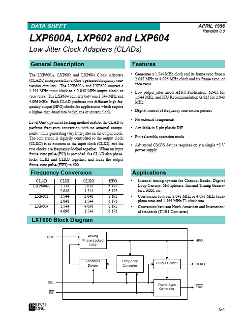
MHz for LXP604) is converted to 1.544 MHz CLKO. When SEL = Low, 1.544 MHz CLKI is converted to higher frequency CLKO (2.048 for LXP600A and LXP602, or 4.096 MHz for LXP604).
and to FSI (if FSI is provided).
ë
+)2 2 High Frequency Outputï HFO is used to derive CLKO. HFO can also clock external
devices. HFO is always a multiple of CLKO (CLKO x2, x3, or x4). Actual frequencies are determined by device, CLKI and CLKO frequencies and Mode Select (SEL) input, as listed in Table 2.
è
‡ 1R H[WHUQDO FRPSRQHQWV
‡ $YDLODEOH LQ åðSLQ SODVWLF ',3
ç
‡ 3LQðVHOHFWDEOH RSHUDWLRQ PRGH
‡ $GYDQFHG &026 GHYLFH UHTXLUHV RQO\ D VLQJOH òè 9 SRZHU VXSSO\
æ
å
$SSOLFDWLRQV
‡ ,QWHUQDO WLPLQJ V\VWHP IRU &KDQQHO %DQNVñ 'LJLWDO /RRS &DUULHUVñ 0XOWLSOH[HUVñ ,QWHUQDO 7LPLQJ *HQHUDð WRUVñ 3%;ñ HWFï
全球各大化学数据库

1. 化合物毒性相关数据库Toxnet /2毒性物质与健康和环境数据库/efdb/TSCATS.htm3. 急性毒性数据库/data/acute/acute.html4. SpectraOnline,Galact /SpectraOnline/Default_ie.htm5. 药物使用指南,USP DI /medlineplus/druginformation.html6。
美国常用药物索引库RxList /7. 有机化合物光谱资料库系统http://www.aist.go.jp/RIODB/SDBS/menu-e.html8. NIST的Chemistry WebBook /chemistry/9. 化合物基本物性库10. 化学物质热力学数据/databases/key1.html11. 溶剂数据库SOLV-DB /solvdb.htm12. 三维结构数据库NCI-3D /nci3d/13. 有机合成手册数据库/14. Beilstein Abstracts /databases/belabs15. 有机合成文献综述数据库/... als/info/index.html16. 预测LogP和LogW /17. 物性、质谱、晶体结构数据库http://factrio.jst.go.jp/18. 网上光谱资料库/SpectraOnline/Default_ie.htm19. 中国科学院学位论文数据库/cgrs全球实用化学化工期刊和数据库网址资源名称:AIChE(美国化学工程师协会)资源地址:/获取途径:部分资源可免费查阅资源名称:American Chemical Society(美国化学学会网站)资源地址:/获取途径:大部分资源可免费查阅,34种期刊(/about.html)全部免费阅览全文。
精选网络化学资源之一常用资源? A. 元素周期表WebElements - /B. 化合物性质(MSDS)ChemFinder服务/化学专家站点/ccd/power/index.shtml化学快查站点/scripts/main.aspVermont安全信息资源公司/msds/index.htmlCornell大学/msdssrch.aspMSDS查找/C. 光谱学数据和有机化合物的查找NIMC站点http://www.aist.go.jp/RIODB/SDBS/menu-e.html化学专家站点ChemExper Chem. Directory - /ccd/power/i ndex.shtmlNIST站点/chemistry/银河网/spconline/有机化学数据库/chemistry/cmp/cmp.htmlD. 家庭教师索引/tutorial.htm#tutorialE. 化学练习题/Malone3... one_site/Malone.htmF. 化学教育期刊索引(JCE)/Journal/Search/index .htmlG. 搜索引擎Google - Alta Vista - /Fast - Hotbot - /Ixquick - /Dog-pile - /H. 化学关键词查找期刊摘要/(free registration, go to data bases)精选网络化学资源之二化学物质的性质? A. 元素周期表1. Web Elements - /2. 其他有图表的元素周期表a. /viselements/pages/periodic_table.htmlb. http://chemlab.p/periodic/periodic.htmlc. /periodictable.htmld. /yogi/periodic/e. /Chemicool/3. Mendeleev表- /~giunta/mendeleev.html4. 其它元素周期表* /okapi/periodic3.htm/CapeCanaveral/4693/index.html/periodic.htm/smarsden/elements.htm/~holler/periodic/periodic.html/Chemistry/Links/refperiodic.html/WebChem/ProjectFrameSet.html//eleme... s/chemistry/rushin/StudentProjects/ElementWebsites/ElectPeriodicTable.htm/pt.htm/wgbh/nova/kaboom/elemental/* /* http://www.tabulka.cz/english/* http://www.vcs.ethz.ch/chemglobe/ptoe/* /* /physics/2000/applets/a2.html5. 元素周期表的目录列表/chemdex/periodic-tables.htmlhttp://www.anachem.umu.se/cgi-bin/pointer.exe?/HSG/GradChemistry.html#TABLES/~swenger/#periodic/m03ptabl.htmlhttp://macedonia.nrcps.ariadne-t... y2.pl?select=01-390/Chemistry/Links/refperiodic.html/periodic_tables.htm#PeriodicTables/education/chemistry/msub9.htm6. 同位素知识/education/isotopes.htm/CoN/index.htmlhttp://140.198.18.108/periodic/isotopes.htmlB. 化合物o 1. MSDS的化合物性质a.ChemFinder服务/b.化学专家/ccd/power/index.shtmlc.化学快查- /scripts/main.aspd.化学飞速- /efdb/Chemfate.htme.Chemidplus - /chemidplus/2. 化学目录(包括部分性质) -a. Aldrich, Sigma, Fluka (now with MSDS) - /3. MSDS的化学目录-a. Arcos and Fisher - /b. JT Baker (&Mallinckrodt) - 4. MSDS 的材料安全数据表a. MSDS在线? /b.牛津大学http://physchem.ox.a:80/MSDS/c. Directory of MSDS compilations, University of Kentucky - IkNe WFuZ2Rvbmd5dQ==FQG/msds/index.htmld. MSDS 搜索引擎Vermont 安全信息资源公司/msds/index.htmlCornell大学/msdssrch.aspMSDS搜索- http://www.m /e. /Chemistry/Links/refmsds.html5. 查找有机化合物的性质a. 有机化学数据库/chemistry/cmp/cmp.htmlb. 点击强力搜索at: /ccd/power/index.shtmlc. 银河- /spconline/d. NIMC站点http://www.aist.go.jp/RIODB/SDBS/menu-e.html6. 化学物质的应用a. ChemExpo Commercial Chemical Profiles? /news/profile.cfm#menub. 化学与化工7. 有机物的溶解性/smurov/orgsoltab.htm/solvdb.htm/Data%20/Table_26.html8. 毒性/ngispgm3/iris/index.html/pubs/factsheets/toxnetfs.html/9. 环境保护基金会的化学物质“计分表”/chemical-prof iles/10. 光谱和热力学性质NIST站点的红外、质谱和热力学数据/chemistry/NIMC站点的核磁共振、红外和质谱数据http://www.aist.go.jp/RIODB/SDBS/menu-e.h tml银河/spconline/化学专家主页/ccd/power/index.shtml红外谱图/~dls/ir/11. 酸碱的浓度、缓冲性质和平衡常数http://155.135.31.26/oliver/chemdata/12. 全美环境计划(UNEP)一个有关安全使用化学品的站点http://irptc.unep.ch/13. 全美癌症数据/nci99/index.asp精选网络化学资源之三化学事实和数据? A. 事实o 1. 基本常数(1986 CODATA推荐值)/cuu/Constants/ind ex.html?/codata86.html2.转换系数http://www.chemie.fu-berlin.de/chemistry/general/units.html/Cv_start.htm? B. 概念o 1. 物质的状态和磁性/cca/documents/dyoung/topics-orig/2. 化学概念和术语化学大百科/chem-ed/scidex.html词汇/high.htm#definitionsof chemical/dictionary//chem/senese/101/glossary.shtmlhttp://netaccess.on.ca/~dbc/cic_hamilton/dictionary/a.html/chem/letters//wldchem/home/refer/aframe.htm//yogi/chemistry/dictionary/词汇和术语/iupac/参见十、化学教育资源3. 实验室操作/che... ety/resources.shtml4. Safety, Ira Remsen quotation - /smurov/re msen.htm5. 核- /3659/nucreact/6. 平衡常数http://www.chem.ualberta.ca/courses/plambeck/p101/p0040x.htmpusmart.ab.ca/plambeck/che/data/p0040x.htmhttp://155.135.31.26/oliver/chemdata//Data%20/Data.htmlhttp://155.135.31.26/oliver/pubdomdb.htm7. pH 值和滴定曲线http://www.science.ubc.ca/~chem/tutorials/pH/index.html/CWIS/DEP... utorial/phmenu.html8.第二定律//9. 有效数字、单位和单位换算a. 有效数字/~giunta/rayleigh.html/~giunta/acspaper.htmlb. 单位/sections/s... sclimate990930.htmlhttp://clive.canoe.ca/CNEWSHeyMartha9911/10_metric.html/sd/08/00101/02/99/10/01/165724.HTMc. 单位换算/vc2/2my/my2_143.html/flightzz.shtml10. 理论化学/TheoryPage/精选网络化学资源之四应用化学? A. 氮、食物和火焰/orgs/aiche/archive/history/h_s_ n2.htmlor .tr/~che/akman/history/h_s_n2.htmlB. 硫酸-硫酸制造、化学工业之门/orgs/aiche/archive/history/h_s_acid.htmlor .tr/~che/akman/history/h_s_acid.htmlC. 石油o 1. 石油:化工原料和能源/orgs/aiche/archive/histor y/h_energy.htmlor .tr/~che/akman/history/h_energy.html2. 现代的石油提炼-一个实例/orgs/aiche/archive/history/h_refine.htmlor .tr/~che/akman/history/h_refine.html3. 化石用于燃料/c... /fossils/index.html4. 石油勘探/c... findoils/index.htmlD. 化学工业o 1. 化学50强(1996) /hotartcl/cenear/960624/prod.html2. 1997 事实和数字/hotartcl/cenear/970623/facts.html3. 2000 事实和数字/hotartcl/cenear/000626/7826intro.htmlE. 化学应用参见二-B-F. 化工中的危险/news.release/osh.t01.htmG. 化工专业引擎- /。
新视野大学英语第二版读写教程第一册答案(unit1

新视野大学英语第二版读写教程第一册答案(unit1ruo gnisol ot esolc emac osla ew tub ,yenom ruo lla esol ew did ylno toN .3 .hsilgnE ni sdneirf htiw etacinummoc ot denrael osla ew tub ,esruoc enilno eht hguorht ygolonhcet eht nrael ew did ylno toN .2 .sruo dna erutluc sih neewteb pag eht degdirb osla eh tub ,egaugnal esenihC eht nrael htimS .rM did ylno toN .1 .IIV .yrgna saw ehs yldrawni elihw ,denrecnoc esoht lla sdrawot yldneirf saw araS yldrawtuO .5 .etilopmi dna gnitlusni eew srehto elihw ,yletilop devaheb dna yltnasaelp ekops stseug emoS .4 .ylimaf eht rof sreh lla devas efiw sih elihw ,gniknird yenom sih lla tneps dnabsuh ehT .3 .nwod ti gnikconk tpek nosnikliW elihw ,pu ecirp eht gniklat tpek kralC nallA .2 .roop ylevitaler era tsew eht ni esoht elihw ,deppiuqe retteb era tsae eht ni seitisrevinU .1 .IV erutcurtS ecnetneS C.01 F.9 O.8 M.7 K.6 H.5 I.4 E.3 B.2 G.1 .V htiw.01 rof .9 ni .8 fo .7 pu .6 ot .5 htiw .4 morf .3 otni .2 pu .1 .VI seitinutroppo .01 muminim .9 stifeneb .8 lautriv .7 tnemtimmoc .6 evitisop .5 gnissarrabme .4 ssecca .3 etacinummoc .2 gnidrawer .1 .III 案答1 tinU 册1 第版2 第语英学大野视新语英学大野视新案答册一第程教写读版二第语英学大野视新]献贡晖清月由文本[ 案答册一第程教写读版二第语英学大野视新nI.01 fo .9 pu .8 ni .7 fo .6 no .5 no .4 no .3 htiw .2 rof .1 .VI esora .01 derednih .9 egnellahc .8 ticilpxe .7 evitcepsrep .6 ecrofnier .5 dettimmoc .4 euqinu .3 evitceffe .2 ytinummoc .1 yralubacoV D.8 C.7B.6 D.5C.4 B.3 A.2 C.1 .II txeT eht fo noisneherpmoC B .5 A .4D.3 B.2C.1 .1 sllikS gnidaeR B noitceS .krow drah ym lla fo stifeneb eht depaer I ,ecnetsisrep fo sraey retfA .emit no stnemngissa dehsinif dna esruoc eht fo sdradnats eht tem I taht os ylluferac emit ym deganam oslaI .ssorca emac I sdrow wen detsil I hcihw ni koobeton a sa llew sa tnew I erehwyreve em htiw yranoitcid llams a deirrac I .ecitcarp fo tol a koot ti ,yas ot sseldeen ,dna egnellahc laer a saw tI .egaugnal ngierof a gninrael ni dedeeccus I taht yas ot duorp ma I .IIX gnitirW derutcurtS B.51 A.41 B.31 A.21 A.11 B.01 a.9 A.8 B.7 C,6 C.5 B.4 B.3 A.2 B .1 ezolC 。
CS6W系列555W模块技术参数及介绍说明书

CS6W-530|535|540|545|550|555MS535 W ~ 555 WMORE POWERMORE RELIABLEComprehensive LID / LeTID mitigation technology, up to 50% lower degradationModule power up to 555 W Module efficiency up to 21.5 %555 WMinimizes micro-crack impactsBetter shading toleranceCompatible with mainstream trackers,cost effective product for utility power plantUp to 4.5 % lower LCOEUp to 5.6 % lower system costCSI Solar Co., Ltd. is committed to providing high quality solar photovoltaic modules, solar energy and battery storage solutions to customers. The company was recognized as the No. 1 module supplier for quality and performance/price ratio in the IHS Module Customer Insight Survey. Over the past 22 years, it has successfully delivered over 88 GW of premium-quality solar modules across theworld.IEC 61215 / IEC 61730 / CEUL 61730 / IEC 61701 / IEC 62716 / Take-e-way* For detailed information, please refer to the Installation Manual.Heavy snow load up to 5400 Pa, wind load up to 2400 Pa*HiKu6 Mono PERCCSI Solar Co., Ltd.199LushanRoad,SND,Suzhou,Jiangsu,China,215129,,********************* The specific certificates applicable to different module types and markets will vary, and therefore not all of the certifications listed herein will simultaneously apply to the products you order or use. Please contact your local Canadian Solar sales representative to confirm the specific certificates available for your Product and applicable in the regions in which the products will be used.PRODUCT CERTIFICATES*ISO 9001:2015 / Quality management systemISO 14001:2015 / Standards for environmental management systemISO 45001: 2018 / International standards for occupational health & safety IEC62941: 2019 / Photovoltaic module manufacturing quality systemMANAGEMENT SYSTEM CERTIFICATES**According to the applicable Canadian Solar Limited Warranty Statement.12YearsYearsEnhanced Product Warranty on Materials and Workmanship*Linear Power Performance Warranty*1st year power degradation no more than 2%Subsequent annual power degradation no more than 0.55%A - AB - BPARTNER SECTIONENGINEERING DRAWING (mm)Rear ViewMounting HoleCS6W-530MS / I-V CURVES* The specifications and key features contained in this datasheet may deviate slightly from our actual products due to the on-going innovation and product enhancement. CSI Solar Co., Ltd. reserves the right to make necessary adjustment to the information described herein at any time without further notice.Please be kindly advised that PV modules should be handled and installed by qualified people who have professional skills and please carefully read the safety and installation instructions before using our PV modules.CSI Solar Co., Ltd.199LushanRoad,SND,Suzhou,Jiangsu,China,215129,,********************VA V A1000 W/m 800 W/m600 W/m 400 W/m200 W/m 5°C 25°C 45°C 65°CMECHANICAL DATA Specification DataCell TypeMono-crystalline Cell Arrangement 144 [2 x (12 x 6) ]Dimensions 2278 ˣ 1134 ˣ 30 mm (89.7 ˣ 44.6 ˣ 1.18 in)Weight 27.6 kg (60.8 lbs)Front Cover 3.2 mm tempered glass with anti-ref -lective coatingFrame Anodized aluminium alloy J-Box IP68, 3 bypass diodes Cable4 mm 2 (IEC), 12 AWG (UL)Cable Length (Including Connector)350 mm (13.8 in) (+) / 250 mm (9.8 in) (-) or customized length*Connector T6 or MC4-EVO2 or MC4-EVO2APer Pallet35 piecesPer Container (40' HQ)700 pieces or 630 pieces (only for US& Canada)* For detailed information, please contact your local Canadian Solar sales and technical representatives.141312111098765432105 10 15 20 25 30 35 40 45 50 55 60 5 10 15 20 25 30 35 40 45 50 55 600 ~ + 10 WFrame Cross Section1413121110987654321TEMPERATURE CHARACTERISTICS SpecificationData Temperature Coefficient (Pmax)-0.34 % / °C Temperature Coefficient (Voc)-0.26 % / °C Temperature Coefficient (Isc)0.05 % / °CNominal Module Operating Temperature 41 ± 3°CMar. 2023. All rights reserved, PV Module Product Datasheet V2.7_ENELECTRICAL DATA | STC*CS6W530MS 535MS 540MS 545MS 550MS 555MSNominal Max. Power (Pmax)530 W 535 W 540 W 545 W 550 W 555 W Opt. Operating Voltage (Vmp)40.9 V 41.1 V 41.3 V 41.5 V 41.7 V 41.9 V Opt. Operating Current (Imp)12.96 A 13.02 A 13.08 A 13.14 A 13.20 A 13.25 A Open Circuit Voltage (Voc)48.8 V 49.0 V 49.2 V 49.4 V 49.6 V 49.8 V Short Circuit Current (Isc)13.80 A 13.85 A 13.90 A 13.95 A 14.00 A 14.05 A Module Efficiency 20.5%20.7%20.9%21.1%21.3%21.5%Operating Temperature -40°C ~ +85°CMax. System Voltage 1500V (IEC/UL) or 1000V (IEC/UL)Module Fire Performance TYPE 1 (UL 61730 1500V) or TYPE 2 (UL 617301000V) or CLASS C (IEC 61730)Max. Series Fuse Rating 25 A Application Classification Class A Power Tolerance* Under Standard Test Conditions (STC) of irradiance of 1000 W/m 2, spectrum AM 1.5 and cell tempe -rature of 25°C.ELECTRICAL DATA | NMOT*CS6W530MS 535MS 540MS 545MS 550MS 555MSNominal Max. Power (Pmax)397 W 401 W 405 W 409 W 412 W416 W Opt. Operating Voltage (Vmp)38.3 V 38.5 V 38.7 V 38.9 V 39.1 V 39.3 V Opt. Operating Current (Imp)10.38 A 10.42 A 10.47 A 10.52 A 10.55 A 10.59 A Open Circuit Voltage (Voc)46.1 V 46.3 V 46.5 V 46.7 V 46.9 V 47.1 V Short Circuit Current (Isc)11.13 A 11.17 A 11.21 A 11.25 A 11.29 A 11.33 A* Under Nominal Module Operating Temperature (NMOT), irradiance of 800 W/m 2, spectrum AM 1.5, ambient temperature 20°C, wind speed 1 m/s.。
马兰士 SR8200说明书

R Model SR8200 User GuideAV Surround ReceiverThe lightning flash with arrowhead symbolwithin an equilateral triangle is intended toalert the user to the presence of uninsulated“dangerous voltage” within the product’senclosure that may be of sufficient magnitudeto constitute a risk of electric shock to persons.The exclamation point within an equilateraltriangle is intended to alert the user to thepresence of important operating andmaintenance (servicing) instructions in theliterature accompanying the product.WARNINGTO REDUCE THE RISK OF FIRE OR ELECTRIC SHOCK,DO NOT EXPOSE THIS PRODUCT TO RAIN OR MOISTURE.CAUTION: TO PREVENT ELECTRIC SHOCK, MATCH WIDEBLADE OF PLUG TO WIDE SLOT, FULLY INSERT.ATTENTION: POUR ÉVITER LES CHOC ÉLECTRIQUES,INTRODUIRE LA LAME LA PLUS LARGE DE LA FICHE DANS LABORNE CORRESPONDANTE DE LA PRISE ET POUSSERJUSQU’AU FOND.NOTE TO CATV SYSTEM INSTALLER:This reminder is provided to call the CATV (Cable-TV) system installer’s attention to Section 820-40 of the NEC which provides guidelines for proper grounding and, in particular, specifies that the cable ground shall be connected to the grounding system of the building, as close to the point of cable entry as practical.NOTE:This equipment has been tested and found to comply withthe limits for a Class B digital device, pursuant to Part 15of the FCC Rules. These limits are designed to providereasonable protection against harmful interference in aresidential installation. This equipment generates, usesand can radiate radio frequency energy and, if notinstalled and used in accordance with the instructions,may cause harmful interference to radio communica-tions. However, there is no guarantee that interferencewill not occur in a particular installation. If this equipmentdoes cause harmful interference to radio or televisionreception, which can be determined by tuning theequipment off and on, the user is encouraged to try tocorrect the interference by one or more of the followingmeasures:-Reorient or relocate the receiving antenna.-Increase the separation between the equipment and receiver.-Connect the equipment into an outlet on a circuit differentfrom that to which the receiver is connected.-Consult the dealer or an experienced radio/TV technician forhelp.NOTE:Changes or modifications not expressly approved by theparty responsible for compliance could void the user’sauthority to operate the equipment.IMPORTANT SAFETY INSTRUCTIONSREAD BEFORE OPERATING EQUIPMENTThis product was designed and manufactured to meet strict quality and safety standards. There are, however, some installation and operation precautions which you should be particularly aware of.1.Read Instructions – All the safety and operating instructionsshould be read before the product is operated.2.Retain Instructions – The safety and operating instructions shouldbe retained for future reference.3.Heed Warnings – All warnings on the product and in the operatinginstructions should be adhered to.4.Follow Instructions – All operating and use instructions should befollowed.5.Cleaning – Unplug this product from the wall outlet beforecleaning. Do not use liquid cleaners or aerosol cleaners. Use a damp cloth for cleaning.6.Attachments – Do not use attachments not recommended by theproduct manufacturer as they may cause hazards.7.Water and Moisture – Do not use this product near water-forexample, near a bath tub, wash bowl, kitchen sink, or laundry tub, in a wet basement, or near a swimming pool, and the like.8.Accessories – Do not place this product on an unstable cart,stand, tripod, bracket, or table. The product may fall, causing serious injury to a child or adult, and serious damage to the product. Use only with a cart, stand, tripod, bracket, or table recommended by the manufacturer, or sold with the product. Any mounting of the product should follow the manufacturer’s instructions, and should use a mounting accessory recommended by the manufacturer.9. A product and cart combination should be moved with care. Quickstops, excessive force, and uneven surfaces may cause theproduct and cart combination to overturn.10.Ventilation – Slots and openings in the cabinet are provided forventilation and to ensure reliable operation of the product and to protect it from overheating, and these openings must not be blocked or covered. The openings should never be blocked by placing the product on a bed, sofa, rug, or other similar surface.This product should not be placed in a built-in installation such asa bookcase or rack unless proper ventilation is provided or themanufacturer’s instructions have been adhered to.11.Power Sources – This product should be operated only from thetype of power source indicated on the marking label. If you are not sure of the type of power supply to your home, consult your product dealer or local power company. For products intended to operate from battery power, or other sources, refer to the operating instructions.12.Grounding or Polarization – This product may be equipped with apolarized alternating-current line plug (a plug having one blade wider than the other). This plug will fit into the power outlet only one way. This is a safety feature. If you are unable to insert the plug fully into the outlet, try reversing the plug. If the plug should still fail to fit, contact your electrician to replace your obsolete outlet. Do not defeat the safety purpose of the polarized plug.AC POLARIZED PLUG13.Power-Cord Protection – Power-supply cords should be routed sothat they are not likely to be walked on or pinched by items placed upon or against them, paying particular attention to cords at plugs, convenience receptacles, and the point where they exit from the product.14.Protective Attachment Plug – The product is equipped with anattachment plug having overload protection. This is a safety feature. See Instruction Manual for replacement or resetting of protective device. If replacement of the plug is required, be sure the service technician has used a replacement plug specified by the manufacturer that has the same overload protection as the original plug.15.Outdoor Antenna Grounding – If an outside antenna or cablesystem is connected to the product, be sure the antenna or cable system is grounded so as to provide some protection against voltage surges and built-up static charges. Article 810 of the National Electrical Code, ANSI/NFPA 70, provides information with regard to proper grounding of the mast and supporting structure, grounding of the lead-in wire to an antenna discharge unit, size of grounding conductors, location of antenna-discharge unit, connection to grounding electrodes, and requirements for the grounding electrode. See Figure 1.16.Lightning – For added protection for this product during a lightningstorm, or when it is left unattended and unused for long periods of time, unplug it from the wall outlet and disconnect the antenna or cable system. This will prevent damage to the product due to lightning and power-line surges.17.Power Lines – An outside antenna system should not be locatedin the vicinity of overhead power lines or other electric light or power circuits, or where it can fall into such power lines or circuits.When installing an outside antenna system, extreme care should be taken to keep from touching such power lines or circuits as contact with them might be fatal.18.Overloading – Do not overload wall outlets, extension cords, orintegral convenience receptacles as this can result in a risk of fire or electric shock.19.Object and Liquid Entry – Never push objects of any kind into thisproduct through openings as they may touch dangerous voltage points or short-out parts that could result in a fire or electric shock.Never spill liquid of any kind on the product.iii20.Servicing – Do not attempt to service this product yourself as opening or removing covers may expose you to dangerous voltage or other hazards. Refer all servicing to qualified service personnel.21.Damage Requiring Service – Unplug this product from the wall outlet and refer servicing to qualified service personnel under the following conditions:a.When the power-supply cord or plug is damaged.b.If liquid has been spilled, or objects have fallen into the product.c.If the product has been exposed to rain or water.d.If the product does not operate normally by following the operating instructions. Adjust only those controls that are covered by the operating instructions as an improper adjustment of other controls may result in damage and will often require extensive work by a qualified technician to restore the product to its normal operation.e.If the product has been dropped or damaged in any way, and f.When the product exhibits a distinct change in performance – this indicates a need for service.22.Replacement Parts – When replacement parts are required, be sure the service technician has used replacement parts specified by the manufacturer or have the same characteristics as the original part. Unauthorized substitutions may result in fire, electric shock, or other hazards.23.Safety Check – Upon completion of any service or repairs to this product, ask the service technician to perform safety checks to determine that the product is in proper operating condition.24.Wall or Ceiling Mounting – The product should be mounted to a wall or ceiling only as recommended by the manufacturer.25.Heat – The product should be situated away from heat sources such as radiators, heat registers, stoves, or other products (including amplifiers) that produce heat.FIGURE 1EXAMPLE OF ANTENNA GROUNDING AS PER NATIONAL ELECTRICAL CODE, ANSI/NFPA 70This Class B digital apparatus complies with Canadian ICES-003.Cet appareil numérique de la Classe B est conforme à la norme NMB-003 du Canada.NEC - NATIONAL ELECTRICAL CODE(NEC ART 250, PART H)FEATURES (2)AMPLIFIER FEATURES (2)AUDIO/VIDEO FEATURES (2)FLEXBILITY FEATURES (2)OTHER FEATURES (2)DESCRIPTION (3)FRONT PANEL (5)FL DISPLAY (7)REAR PANEL (9)REMOTE CONTROL UNIT RC3200A (11)LOADING BATTERIES (11)ACTIVATING THE RC3200A (11)OPERATING DEVICES (12)REMOTE-CONTROLLABLE RANGE (12)OPERATING AMP & TUNER (13)SHOW THE STATUS OF SR8200 ON THE LCD OF RC3200A (15)WORKING WITH MODES (16)ADJUSTING THE SETTINGS (16)LEARNING COMMANDS (18)RECORDING MACROS (18)RC3200 EDIT (20)IMPORTANT NOTICES (21)CLEANING RC3200A (21)HOW TO RESET THE RC3200A (21)CONNECTING (22)CONNECTING THE AUDIO COMPONENTS (22)CONNECTING THE VIDEO COMPONENTS (22)CONNECTING THE VIDEO COMPONENTS WITH S-VIDEO / COMPONENT (23)CONNECTING THE MONITOR AND VIDEO CAMERA (23)CONNECTING THE DIGITAL / 7.1CH INPUT (24)CONNECTING THE SPEAKERS (24)CONNECTING THE SPEAKERS WITH EXTERNAL AMPLIFIER (25)CONNECTING THE ANTENNA AND POWER CORD (25)CONNECTING THE REMOTE CONTROL BUS (RC-5) (26)CONNECTING FOR THE MULTI ROOM (26)SETUP (27)ON SCREEN DISPLAY MENU SYSTEM (27)INPUT SETUP (ASSIGNABLE DIGITAL INPUT) (28)SPEAKER SETUP (28)PREFERENCE (30)SURROUND (31)PL2 (PRO LOGIC II) MUSIC PARAMETER (31)MULTI ROOM (32)7.1 CH INPUT LEVEL (32)DC TRIGGER SETUP.................................................................................32BASIC OPERATION (PLAY BACK) (33)SELECTING AN INPUT SOURCE (33)SELECTING THE SURROUND MODE (33)ADJUSTING THE MAIN VOLUME (33)ADJUSTING THE TONE(BASS & TREBLE) CONTROL (33)TEMPORARILY TURNING OFF THE SOUND (34)USING THE SLEEP TIMER (34)NIGHT MODE (34)DIALOGUE NORMALIZATION MESSAGE (34)SURROUND MODE (35)OTHER FUNCTION (39)TV AUTO ON/OFF FUNCTION (39)ATTENUATION TO ANALOG INPUT SIGNAL (39)LISTENING OVER HEADPHONES (39)VIDEO ON/OFF (39)DISPLAY MODE (39)SELECTING ANALOG AUDIO INPUT OR DIGITAL AUDIO INPUT (39)RECORDING AN ANALOG SOURCE (40)RECORDING A DIGITAL SOURCE (40)7.1 CH INPUT (41)AUX2 INPUT (41)BASIC OPERATION (TUNER) (42)LISTENING TO THE TUNER (42)PRESET MEMORY (42)MULTI ROOM SYSTEM (45)MULTI ROOM PLAYBACK USING THE MULTI ROOM OUT TERMINALS (45)MULTI ROOM PLAYBACK USING THE MULTI SPEAKER TERMINALS (45)OPERATION TO MULTI ROOM OUTPUTS WITH THE REMOTE CONTROLLER FROM SECOND ROOM (45)TROUBLESHOOTING (46)1AMPLIFIER FEATURES• THX Select certified6ch amplifiers have enough power for even the most difficult conditions found in large rooms.Enormous power reserves endow the system with substantial dynamic ability at high sound levels.130 watts to each of the six main channels the power amp section features an advanced, premium high- storage power supply capacitors, and fully discrete output stages housed in cast aluminum heat sinks .• Current feedback 6ch AmplifierCurrent feedback topology combines total operation stability with excellent frequency response,while requiring only minimal amounts of negative feedback.It makes excellent transient response and superb sonic transparency. AUDIO/VIDEO FEATURES•THX SURROUND EX built in to decode the additional two surround buck channels from THX Surround EX-encoded DVDs and laserdiscs.•DTS-ES decoder built in to decode the impeccable 6.1-channel discrete digital audio from DTS-ES encoded DVD-Video discs, DVD-Audio discs, CDs and laserdiscs.•DOLBY DIGITAL decoder built in to decode the 5.1-channel digital audio of DVDs, Digital TV, HDTV, satellite broadcasts and other sources.•DOLBY PRO LOGIC II decoder provides better spatiality and directionality on Dolby Surround program material; provides a convincing three-dimensional sound field on conventional stereo music recordings.•CIRCLE SURROUND decoder built in to decode surround sound from any stereo or passive matrix-encoded material.•Multi-channel (7.1ch)direct inputs accommodate future multi-channel sound formats or an external digital decoder.•192kHz/24-bit D/A CONVERTERS for all channels.•ADDC (Advanced Double Differential Converter) output for STEREO playback.•Source Direct mode bypasses, tone controls and bass management for purest audio quality.•Two sets of Y/Cr/Cb component video inputs and component video outputs provide unsurpassed video quality and switching flexibility from component video sources.•Easy to use on-screen menu system in all video monitor output.FLEXBILITY FEATURESFUTURE-PROOF INTERFACE ARCHITECTUREa versatile RS232 port allows the SR8200’s internal Flash Memory to be directly computer accessed for installing such future upgrades as new DSP algorithms, new surround formats/parameters, and other types of processing updates.MULTIROOM CAPABILITYa full set of line outs for audio, composite video, allows for set-up of an additional system in another room, and complete second-room control can be achieved with such A/V distribution control systems as Xantech, Niles, to name but a few.Digital I/OAssignable six Digital inputs, for connection to other sources, such as DVD,DSS or CD.A optical Digital input on front AUX1 terminals, for connection to portable player or game.Two Digital outputs for connection to digital recorder as CD-R or MD. OTHER FEATURES• High-quality AM/FM tuner with 50 station presets.• 2way programmable learning remote control RC3200A.23E N G L ITHX ® is an exclusive set of standards and technologies established by the world-renowned film production company, Lucasfilm Ltd. THX resulted from George Lucas’ desire to reproduce the movie soundtrack as faithfully as possible both in the movie theater and in the home theater.THX engineers developed patented technologies to accurately translate the sound from a movie theater environment into the home,correcting the tonal and spatial errors that occur.When the THX mode of the SR8200 is on, three distinct THX technologies are automatically added:Re-Equalization-restores the correct tonal balance for watching a movie in a home environment.These sounds are otherwise mixed to be brighter for a large movie theater. Re-EQ compensates for this and prevents the soundtracks from being overly bright and harsh when played in a home theater.Timbre Matching-filters the information going to the surround speakers so they more closely match the tonal characteristics of the sound coming from the front speakers.This ensures seamless panning between the front and surround speakers.Adaptive Decorrelation-slightly changes one surround channel’s time and phase relationship with respect to the other surround channel.This expands the listening position and creates with only two surround speakers the same spacious surround experience as in a movie theater with multiple surround speakers.The Marantz SR8200 was required to pass a rigorous series of quality and performance tests, in addition to incorporating the technologies explained above, in order to be THX Ultra certified by Lucasfilm Ltd.THX Ultra requirements cover every aspect of performance including pre-amplifier and power amplifier performance and operation, and hundreds of other parameters in both the digital and analog domain.Movies which have been encoded in Dolby Digital, DTS, Dolby Pro Logic,stereo and Mono will all benefit from the THX mode when being viewed.The THX mode should only be activated when watching movies which were originally produced for a movie theater environment.THX need not be activated for music, movies made especially for TV,or shows such as sports programming, talk shows, etc.This is because they were originally mixed for a small room environment.“Lucasfilm ®” and “THX ®” are registered trademarks of Lucasfilm Ltd.Lucasfilm and THX are trademarks or registered trademarks of Lucasfilm Ltd. ©Lucasfilm Ltd. & TM. Surround EX is a jointly developed technology of THX and Dolby Laboratories, Inc. and is a trademark of Dolby Laboratories, Inc. All rights reserved. Used under authorization.THX Surround EX - Dolby Digital Surround EX is a joint development of Dolby Laboratories and the THX division of Lucasfilm Ltd.In a movie theater, film soundtracks that have been encoded with Dolby Digital Surround EX technology are able to reproduce an extra channel which has been added during the mixing of the program.This channel, called Surround Back, places sounds behind the listener in addition to the currently available front left, front center,front right, surround right, surround left and subwoofer channels.This additional channel provides the opportunity for more detailed imaging behind the listener and brings more depth, spacious ambience and sound localization than ever before.Movies that were created using the Dolby Digital Surround EX technology when released into the home consumer market may exhibit a Dolby Digital Surround EX logo on the packaging.A list of movies created using this technology can be found on the Dolby web site athttp ://.“SURROUND EX ™” is a trademark of Dolby Laboratories. Used under authorization.DTS was introduced in 1994 to provide 5.1 channels of discrete digital audio into home theater systems.DTS brings you premium quality discrete multi-channel digital sound to both movies and music.DTS is a multi-channel sound system designed to create full range digital sound reproduction.The no compromise DTS digital process sets the standard of quality for cinema sound by delivering an exact copyof the studio master recordings to neighborhood and home theaters.Now, every moviegoer can hear the sound exactly as the moviemaker intended.DTS can be enjoyed in the home for either movies or music on of DVD’s, LD’s, and CD’s.“DTS” and “DTS Digital Surround” are trademarks of Digital Theater Systems, Inc.DTS-ES Extended Surround is a new multi-channel digital signal format developed by Digital Theater Systems Inc. While offering high compatibility with the conventional DTS Digital Surround format, DTS-ES Extended Surround greatly improves the 360-degree surround impression and space expression thanks to further expanded surround signals. This format has been used professionally in movie theaters since 1999.In addition to the 5.1 surround channels (FL, FR, C, SL, SR and LFE),DTS-ES Extended Surround also offers the SB (Surround Back)channel for surround playback with a total of 6.1 channels. DTS-ES Extended Surround includes two signal formats with different surround signal recording methods, as DTS-ES Discrete 6.1 and DTS-ES Matrix 6.1.]Dolby Digital identifies the use of Dolby Digital (AC-3) audio coding for such consumer formats as DVD and DTV. As with film sound, Dolby Digital can provide up to five full-range channels for left, center, and right screen channels, independent left and right surround channels,and a sixth ( ".1") channel for low-frequency effects.Dolby Surround Pro Logic II is an improved matrix decoding technology that provides better spatiality and directionality on Dolby Surround program material; provides a convincing three-dimensional soundfield on conventional stereo music recordings; and is ideally suited to bring the surround experience to automotive sound. While conventional surround programming is fully compatible with Dolby Surround Pro Logic II decoders, soundtracks will be able to be encoded specifically to take full advantage of Pro Logic II playback,including separate left and right surround channels. (Such material is also compatible with conventional Pro Logic decoders.)Circle Surround is backward compatible, such that surround playback is possible from any stereo or passive matrix-encoded material.Five full-bandwidth, discrete channels of information can be extracted from an enormous library of material not multi-channel encoded.These sources include many of today’s DVDs and laser discs, as well as most all video tape, VCD, Compact Disc, radio and television broadcast material.Circle Surround and the symbol are trademarks of SRS Labs, Inc.Circle Surround technology is incorporated under license from SRS Labs, Inc.45E N u MEMO (memory) buttonPress this button to enter the tuner preset memory numbers or station names.i TUNING UP / DOWN buttonsPress thses buttons to change the frequency or the preset number.o F/P (FREQUENCY / PRESET) buttonDuring reception of AM (MW/LW) or FM, you can change the function of the UP/DOWN buttons for scanning frequencies or selecting preset stations by pressing these buttons.!0T-MODE buttonPress this button to select the auto stereo mode or mono mode when the FM band is selected.The “AUTO ” indicator lights in the auto stereo mode.!1P.SCAN (preset scan) buttonThis button is used to scan preset stations automatically.When pressed, the tuner starts scanning the all preset stations. Press again to cancel the P-SCAN.!2VOLUME control knobAdjusts the overall sound level. Turning the control clockwise increases the sound level.!3ATT (Attenuate) buttonIf the selected analog audio input signal is greater than the capable level of internal processing, PEAK indicator will light. If this happens,you should press the ATT button. “ATT ” is displayed when this function is activated.The signal-input level is reduced by about the half. Attenuation will not work with the output signal of “REC OUT” (TAPE, CD-R/MD, VCR1and VCR2 output). This function is memorized for each input function.q POWER switch and STANDBY indicatorWhen this switch is pressed once, the unit turns ON and display appears on the display panel. When pressed again, the unit turns OFF and the STANDBY indicator lights.When the STANDBY indicator is turned on, the unit is NOT disconnected from the AC power.w SELECT (MULTI FUNCTION MODESELECT) buttonPress this button to change the mode for MULTI FUNCTION control dial.e SURROUND MODE Selector & MULTIFUNCTION control dialThis dial changes surround mode sequentially or select contents of OSD menu system.r ENTER (MULTI FUNCTION ENTER)buttonPress this button to enter the setup by MULTI FUNCTION dial.t DISPLAY mode buttonWhen this button is pressed, the FL display mode is changed as NORMAL → Auto Off → Off and the display off indicator(DISP ) lights up in condition of DISPLAY OFF.y CLEAR buttonPress this button to cancel the station-memory setting mode or preset scan tuning.!4MUTE buttonPress this button to mute the output to the speakers. Press it again to return to the previous volume level.!5INPUT FUNCTION SELECTOR buttons (AUDIO/ VIDEO)These buttons are used to select the input sources.The video function selector, such as TV, DVD, DSS, VCR1 and VCR2, selects video and audio simultaneously.Audio function sources such as CD, TAPE, CDR/MD, TUNER, and 7.1CH-IN may be selected in conjunction with a Video source.This feature (Sound Injection) combines a sound from one source with a picture from another.Choose the video source first, and then choose a different audio source to activate this function.Press TUNER button to switch the between FM or AM.!6AUX1 input jacksThese auxiliary video/audio and optical digital input jacks accept the connection of a camcorder, portable DVD, game etc.!7AUX1 buttonThis button is used to select the AUX1 input source.!8AUX2 buttonThis button is used to select the AUX2 (L/R input of 7.1 CH. IN).!9S. (Source) DIRECT buttonWhen this button is pressed, the tone control circuitry is bypassed as well as Bass Management.Notes:•The surround mode is automatically switched to AUTO when the source direct function is turned on.•Additionally, Speaker Configurations are fixed automatically as follow.•Front SPKR = Large, Center SPKR = Large, Surround SPKR = Large, Sub woofer = On@0NIGHT buttonThis button is used to set night mode. This feature reduces the input level of dolby digital sources by 1/3 to 1/4 at their loudest thresholds, preventing the dynamic range or loud sounds without restricting the dynamic range or volume of other sounds or at less than maximum levels.@1SLEEP buttonSet the sleep timer function with this button.@2A/D (Analog/Digital) SELECTOR button This is used to select between the analog and digital inputs.Note:•This button is not used for an input source that is not set to a digital input in the system setup menu.@3M-SPKR (Multi Room Speaker) button Press this button to activate the Multiroom Speaker system . “M-SPKR” indicator will light in the display.@4MULTI (Multi Room) buttonPress this button to activate the Multiroom system . “MULTI ” indicator will light in the display.@5PHONES jack for stereo headphones This jack may be used to listen to the SR8200’s output through a pair of headphones. Be certain that the headphones have a standard 1 / 4" stereo phone plug. Note that the main room speakers will automatically be turned off when the headphone jack is in use. Notes:•When using headphones, the surround mode will automatically change to STEREO.• The surround mode returns to the previous setting as soon as the plug is removed from the jack.@6INFRARED transmitting sensor window This window transmits infrared signals for the remote control unit.@7INFRARED receiving sensor windowThis window receives infrared signals for the remote control unit.6。
整车强度多工况CAE分析规范
整车强度多工况CAE分析规范1 标题/摘要1.1 标题1.2 摘要本规范的目的在于指导大家如何建立整车强度计算的模型1.3 分析内容整车强度多工况分析,主要分析整车结构中是否存在不满足要求的位置。
1、根据计算结果,评价局部区域结构是否合理2、根据计算结果,评价存在局部应力集中的位置是否满足强度的要求2 建模流程图3 建模工具以下软件是本次建模的工具4 建模指导4.1 内容建模部件主要包括以下部分:✧白车身✧所需底盘零件✧各部件间的连接方式✧白车身配重✧多工况载荷✧载荷加载✧计算控制参数✧…4.2 建模方法某一位置的载荷情况:后悬安装点:板簧车,左右位置对称后悬安装点:螺簧车,潘哈杆安装仅一侧有,其余位置左右对称1、求解序列控制卡SOL:本分析属于静力分析,求解序列为SOL 1012、求解时间控制卡TIME:设定求解器的最大执行时间,单位为分钟3、输出控制:输出选项在工况控制卡(GLOBAL_CASE_CONTROL)中定义4、控制参数PARAM:主要有AUTOSPC,COUPMASS,K6ROT,POST,WTMASSAUTOSPC::自动删除不连接自由度COUPMASS:计算一致质量矩阵WTMASS:质量转换因子4.3 分析要求1、根据要求建立正确的模型,特别是焊接边及螺栓连接位置;2、检查提供的硬点载荷及正确加载;3、根据计算的结果,初步检查是否合理;4、对于计算合理的结果,对结果进行正确的评价。
4.3.1 结果处理1、对于计算合理的结果,利用HW经行结果的后处理,2、整车的强度计算,以节点位置的vonmises应力为计算的应力结果;3、强度结果的评价按照第四强度理论,许用应力[σ]的确定按照目前多工况强度评价标准5 技术要求5.1 前处理检查必须进行以下前处理检查:●有没有未连接的部件●多节点的1D单元有没有自由端●焊点的位置及连接是否正确●载荷加载位置是否正确●加载的载荷是否正确●计算的控制卡片是够正确●计算方法是否是惯性释放●……5.2 求解检查及结果检查1、先试算模型,看是否报错。
CS5460A中文数据手册
l 片内功能:可以测量电能(有功),I *V,IRMS 和 VRMS ,具有电能-脉冲转换功能
l 可以从串行EEPROM 智能“自引导”,不需要微 控制器
l AC 或DC 系统校准 l 具有机械计度器/步进电机驱动器 l 符合IEC687/1036 ,JIS 工业标准 l 功耗<12mW l 优化的分流器接口 l V对I的相位补偿 l 单电源地参考信号 l 片内2.5V 参考电压(最大温漂60ppm/℃) l 简单的三线数字串行接口 l 看门狗定时器 l 内带电源监视器 l 电源配置
VA+ = +5 V; VA- = 0V; VD+ = +3.3V~+5 V
概述
CS5460A 是一个包含两个ΔΣ模-数转换 器(ADC)、高速电能计算功能和一个串行接 口的高度集成的ΔΣ 模-数转换器。它可以精确 测量和计算有功电能、瞬时功率、IRMS 和VRMS , 用于研制开发单相2 线或3 线电表。CS5460A 可以使用低成本的分流器或互感器测量电流,使 用分压电阻或电压互感器测量电压。CS5460A 具有与微控制器通讯的双向串口,芯片的脉冲输 出频率与有功能量成正比。CS5460A 具有方便 的片上AC/DC 系统校准功能。
cs5460a单相双向功率电能ic特性rms具有电能脉冲转换功能可以从串行eeprom智能自引导不需要微控制器ac或dc系统校准符合iec6871036jis工业标准片内25v参考电压最大温漂60ppm电源配置va0v
HMC616 运动控制器硬件手册说明书

HMC616运动控制器硬件手册Version1.1版权说明本手册版权归深圳市浩川自动化技术有限公司所有,未经浩川自动化公司书面许可,任何人不得翻印、翻译和抄袭本手册中的任何内容。
涉及HMC控制器软件的详细资料以及每个指令的介绍和例程,请参阅VBASIC软件手册。
本手册中的信息资料仅供参考。
由于改进设计和功能等原因,浩川自动化公司保留对本资料的最终解释权!内容如有更改,恕不另行通知!调试机器要注意安全!请务必在机器中设计有效的安全保护装置,并在软件中加入出错处理程序,否则所造成的损失,浩川自动化公司没有义务或责任对此负责。
目录HMC616运动控制器硬件手册 (1)第一章控制器简介 (1)1.1连接配置 (1)1.2安装和编程 (2)1.3产品特点 (2)第二章硬件描述 (3)2.1HMC616系列型号规格 (3)2.1.1订货信息: (3)2.2HMC616接线 (4)2.2.1电源接口: (5)2.2.2通讯接口: (5)2.2.3RS232接口: (6)2.2.4通用输入信号: (7)2.2.5通用输出: (8)2.2.6ADDA信号 (9)2.2.7U盘接口信号: (9)2.2.8轴接口信号: (9)第三章扩展模块 (12)第四章常见问题 (12)第五章硬件安装 (13)5.1HMC616安装 (13)第一章控制器简介HMC是浩川自动化推出的独立式运动控制器型号简称。
HMC616系列控制器支持最多达24轴直线插补、任意圆弧插补、空间圆弧、螺旋插补、电子凸轮、电子齿轮、同步跟随、虚拟轴设置等;采用优化的网络通讯协议可以实现实时的运动控制。
单个电脑最多支持达256个HMC控制器同时链接。
1.1连接配置典型连接配置图HMC运动控制器支持以太网,USB,CAN,485等通讯接口,通过CAN总结可以连接各个扩展模块,从而扩展输入输出点数或运动轴(CAN总线两端需要并接120欧姆的电阻)。
HMC运动控制器支持U盘保存或读取数据(30x系列除外)。
J. Label. Compd. Radiopharm. 2004, 47, 821–835.

JOURNAL OF LABELLED COMPOUNDS AND RADIOPHARMACEUTICALSJ Label Compd Radiopharm2004;47:821–835.Published online in Wiley InterScience().DOI:10.1002/jlcr.870Research ArticleIsotope labeled‘HEA Moiety’in the synthesisof labeled HIV-protease inhibitors–Part1I.Victor Ekhato1,*,Yuan Liao1,2and Mihaela Plesescu1,31Bristol-Myers Squibb Company,Pharmaceutical Research Institute,5Research Parkway,Wallingford,CT06492,USA2Pfizer Global Research and Development,Ann Arbor,MI48105,USA3Millennium Pharmaceuticals,Cambridge,MA023139,USASummary[(S)-10-((N-tert-Butyloxycarbonyl)amino)-2S-[2H5]phenyl-ethyl]oxirane11,made from [2H5]-bromobenzene,was transformed into the HIV-protease inhibitors[2H5]-DPH 153893and[2H5]-DPH140662.Both compounds are members of the hydroxyethy-lamine class of protease inhibitors(HIV-PIs).The method of synthesis is applicable to members of this class and the HEE group of HIV-PIs.Copyright#2004John Wiley &Sons,Ltd.Key Words:protease inhibitor;anti-HIV;AIDS;[2H5]-HEA isostereIntroductionDPH153893and DPH140662,like amprenavir1and saquinavir,2are members of the hydroxyethylamine(HEA)isostere class of HIV protease inhibitors(HIV-PIs).3The two compounds are highly potent HIV-aspartyl protease inhibitors with an average IC90of4–8nM against wild-type viruses. Both were selected for pre-clinical evaluation as potential new generation anti-HIV drugs.4Aspects of the studies involved LC-MS analysis and the stable isotope-labeled forms of DPH153893and DPH140662were needed as internal standards.We wanted to make the penta-deuterated DPH153893and DPH 140662molecules in which the[2H5]is situated at the core as the[phenyl ring-2H5]-HEA.We preferred to make the penta-deuterated analog based on the calculation that the molecular weight is sufficiently increased,such that overlap with other ions due to isotopic mass distribution is avoided.*Correspondence to:I.V.Ekhato,Bristol-Myers Squibb Company,Pharmaceutical Research Institute, 5Research Parkway,Wallingford,CT06492,USA.E-mail:ihoezo.ekhato@Copyright#2004John Wiley&Sons,Ltd.Received15July2003Since both compounds possess the HEA core structure,we planned to prepare DPH153893and DPH140662from a common labeled precursor bearing the elements of the[phenyl ring-2H5]-HEA moiety.We believe that the phenyl group of the HEA sub-unit is metabolically stable,since metabolites have not been reported.5Similarly,these metabolites are absent from our internal study6of DPH153893or DPH140662.As a result,we were encouraged to explore the current synthesis with the prospect that a protease inhibitor containing the[phenyl ring-2H5]-HEA moiety might,in addition to our initial reason for synthesis,be suitable for in vivo investigation.By routine reactions we made the required[2H5]-intermediate from[2H5]-bromobenzene and transformed this compound into[2H5]-DPH153893and[2H5]-DPH 140662.Results and discussionIn the synthetic literature on anti-HIV protease inhibitors,unlabeled(1S,2S)-(1-oxiranyl-2-[2H5]phenylethyl)-carbamic acid tert-butyl ester11is extensively used as an intermediate3,7for synthesis of aspartyl protease inhibitors.We considered11to be an attractive key intermediate from which to make[2H5]-protease pound11,Figure1,has the epoxide functionality from which to build[2H5]-DPH153893and[2H5]-DPH140662.In addition,11 provides the[phenyl ring-2H5]-HEA isostere core of both inhibitors.Unlike previous work,7the present approach does not draw on any chiral pools of reagents,such as optically pure amino acids or derivatives,to construct11. Therefore,constructing the[2H5]-labeled carbon skeleton from[2H5]-bromo-benzene1with the desired1S,2S-configuration in11was a challenging task. To address this point,we implemented a facially selective syn-aldol condensation reaction with S-4-benzyl-(3-[2H5]phenylpropionyl)-oxazolidin-2-one5.[2H5]-Bromobenzene was used to prepare compound5,and theSYNTHESIS OF LABELED HIV-PROTEASE INHIBITORS823 sequence of routine reactions that was employed is shown in Scheme1.Thus, following a lithium-halogen exchange reaction with[2H5]-bromobenzene1, DMF was added and acid workup provided the aldehyde,2.A Wittig-type homologation protocol8with compound2furnished3-[2H5]phenylacrylic acid ethyl ester,3.The carboxylic acid made by the hydrolysis of3was activated as the mixed pivaloyl anhydride,and reacted with(S)-(-)-4-benzyl-N-lithio-2-oxazolidinone,according to a literature procedure,9to form(S)-4-benzyl-3-(3-[2H5]phenylacryloyl)-oxazolidin-2-one,pound4was saturated by subjecting it to Pd/C catalyzed hydrogenation to furnish(S)-4-benzyl-3-(3-[2H5]phenylpropionyl)-oxazolidin-2-one,5.2222Et4Scheme1.Conversion of[2H5]-bromobenzene into the acyl oxazolidinone5to enable the asymmetric synthesis of11To complete the required carbon skeleton and simultaneously achieve the desired(S,S)-configuration,compound5was condensed with(benzyloxy) acetaldehyde,10as shown in Scheme2.The combination of dibutylboron triflate and diisopropylethylamine reagent resulted in the highly diastereofa-cially selective syn-aldol condensation reaction yielding6.In the manner described in the literature,11lithium peroxide was used to cleave the amide bond in compound6to obtain(2S,3S)-[(2-[2H5]benzyl-4-(benzyloxy)-3-hydroxybutyric acid,7,in84%pound7was refluxed in a solution of toluene containing diphenylphosphoryl azide and triethylamine to produce 8,an oxazolidinone.Formation of compound8is explained by the intra-molecular cyclization reaction of the intermediate isocyanate with the participation of the neighboring hydroxy group,as described in the literature.10The deprotection of8and the formation of(1S,2S)-1-[N-tert-butyloxycarbonyl)amino]-1-[25H5]benzyl-3-(benzyloxy)propan-2-ol,9,wasachieved in a one-pot pound5was subsequently hydrogenated under Pd/C catalysis to yield10(see Scheme2).The diol grouping in10was converted to the epoxide ring by a modified literature protocol12to give11(Scheme3).Specifically,compound10was treated with1-(bromocarbonyl)-1-methylethyl acetate in ethanol-free chloro-form at08C,converting it to an intermediate bromohydrin.The bromohydrin was cyclized by treatment with a solution of sodium methoxide in THF to provide(1S,2S)-(1-oxiranyl-2-[2H5]phenyl-ethyl)-carbamic acid tert-butyl ester,11,in73%yield.From intermediate11we proceeded to make[2H5]-DPH153893and[2H5]-DPH140662.At the second step in the reaction sequence isobutylamine wasreacted with11in hot isopropyl alcohol to pound12is the lastintermediate common to both synthetic targets,i.e.the reaction step after 12is the point of divergence of the reaction sequences to DPH 140662and DPH 153893.In order to make [2H 5]-DPH 140662,compound 12was treated with 4-nitro-benzenesulfonyl chloride in the presence of potassium carbonate as acid scavenger.After removal of the Boc group,13was obtained as the methanesulfonic acid salt in 80%overall yield over the two steps.By a standard coupling method with EDC.HCl,4-methylmorpholine and HOBt 13in DMF,compound 13and Boc-l -tert -leucine formed the Boc protected 14.We found that the stepwise sequence of coupling Boc-l -tert -leucine to make the Boc protected 14,the removal of Boc to yield 14and the coupling reaction of compound 14with IS066(IS066was generously supplied bythe 11into 14via compound 12,a commonintermediate to [2H 6]-DPH 153893and [H 5]-DPH 140662SYNTHESIS OF LABELED HIV-PROTEASE INHIBITORS 825Department of Chemical Process,DuPont Pharmaceuticals Company,Wilmington,DE)to give 15,as shown in Scheme 4,was the best sequence for making [2H 5]-DPH 140662.An alternative single coupling reaction to DPH 140662from 13was complicated by intra-molecular cyclization of the dipeptide reagent under our reaction conditions.Chromatographic purifica-tion was required to obtain 15,and then only in poor yield.The single coupling approach was therefore abandoned.A standard coupling protocol in DMF containing EDC.HCl,HOBt and 4-methylmorpholine as acid scavenger converted 14to compound 15.After Pd/C catalyzed hydrogenation of 15to the 4-aminobenzenesulfonamide,the Boc group was removed with TFA-Et 3SiH and the reaction mixture was neutralized with NaHCO 3to provide [2H 5]-DPH 140662in 61%yield.By substituting 3-nitrobenzenesulfonyl chloride for 4-nitrobenzenesulfonyl chloride in Scheme 3,and following a sequence of reactions analogous to Schemes 3and 4,we accomplished the synthesis of [2H 5]-DPH 153893in comparable yield.ConclusionTwo HIV protease inhibitors were specifically labeled with [2H 5]at the HEA sub-unit by transforming [2H 5]-bromobenzene into a common intermediate for these agents.The intermediate was made using established reactionsthat 14into [2H 5]-DPH 140662I.V.EKHATO ET AL.826included an asymmetric reaction step.The intermediate was used to create the[phenyl ring-2H 5]labeled HEA core structure of DPH 140662and DPH 153893.Very high deuterium incorporation was achieved by the sequence we have described and the synthetic approach may be applicable,with some modifications,to other HIV-protease inhibitors.ExperimentalAll reactions were carried out under an atmosphere of argon unless otherwise specified.Solvents were commercial grade and used without purification or drying.Column chromatography was carried out on Merck Kiesegel 60(230m)silica gel.Flash chromatographic separations were on a Biotage Flash System using a pre-packed silica gel cartridge.TLC visualization reagents included (10%iodine plus 10%AcOH)in 40%aqueous KI.1H NMR spectra were recorded at 300,400or 500MHz.Chemical shifts are given in ppm relative to tetramethylsilane (TMS).Only the important IR absorptions (cm À1)and the molecular ion and/or base peaks in MS are given.HPLC columns used include Zorbax Rx C 18,Discovery Amide C 16,and Waters Symmetry C 18columns.4S-Benzyl-3-(3-[2H 5]phenyl-propionyl)-oxazolidin-2-one,%5To a stirred solution of [2H 5]-phenylacrylic acid (10.1g,65.07mmol,see Scheme 1for preparation)and 4-methylmorpholine (7.15ml,65.07mmol)in dry THF (120ml)maintained at À788C with a dry ice-acetone bath was added trimethylacetyl chloride (8.01ml,65.07mmol).After 30min the cold bath was replaced with an ice-water bath and the reaction was stirred for another 45min.The precipitate was removed by filtration,and the filtrate was transferred to a solution of N -lithio-oxazolidinone that was pre-generated as follows.(S)-(-)-4-Benzyl-2-oxazolidinone (11.53g,65.07mmol)in dry THF (120ml)was stirred under argon atmosphere at À788C while BuLi (1.6M solution in hexanes,40.6ml,65.07mmol)was added dropwise.The solution was stirred at À788C for 1.0h and the above filtrate,a solution of mixed anhydride in THF,was added in one portion.The reaction was quenched after 1h with saturated NH 4Cl solution (100ml)and the organic phase was separated.The aqueous portion was further extracted with ethyl acetate (3Â200ml),the combined organic extract was dried and evaporated to dryness to give (S)-4-benzyl-3-(3-[2H 5]phenylacryloyl)-oxazolidin-2-onepound 4was dissolved in ethyl acetate (150ml)and a suspension of 10%Pd/C (1.2g)in ethyl acetate (20ml)was added.After the reaction mixture was degassed,it was stirred under a hydrogen atmosphere for 3h and filtered through a pad of Celite to remove the spent catalyst.The filtrate was evaporated to a product which crystallized from EtOAc-hexane to give 5(17.10g,84%).1H NMR (400MHz)d 2.74(dd,1H),3.03(m,2H),3.28(m,SYNTHESIS OF LABELED HIV-PROTEASE INHIBITORS 8273H),4.16(m,2H),4.65(m,1H),7.17(d,2H)and 7.32(m,3H).13C NMR (75MHz)d 30.30,37.12,37.94,55.17,66.26,127.4,128.0,128.2,129.0,129.5,140.4,153.4and 172.5.IR n max (CHCl 3)2276,1785,1699,1490,1478,1390,1372,and 1202cm À1.4S-Benzyl-3-[(2S-[2H 5]benzyl-4-(benzyloxy)-3S-hydroxy-butyryl)]-oxazoli-din-2-one,%6To a stirred solution 4S-benzyl-3-(3-[2H 5]phenylpropionyl)-oxazolidin-2-one 5(23.68g,75.3mmol)in CH 2Cl 2(140ml)at 08C was added dibutylboron triflate (1.0M solution in dichloromethane,98.0ml,98mmol)followed by diisopro-pylethylamine (19.67ml,112.97mmol).After stirring the mixture for 1h at room temperature it was cooled to À788C and a solution of (benzyloxy)ace-taldehyde (20g,133.17mmol)in CH 2Cl 2(30ml)was added.The reaction mixture was stirred for 30min at À788C and warmed to room temperature for 2h.A phosphate buffer of pH 7.3(40ml)was added and while the reaction was cooled to 08C,methanol (140ml)was added followed by a mixture of (2:1)MeOH and 30%H 2O 2(180ml).The resulting mixture was stirred for 1h,concentrated to a small volume and extracted with EtOAc (2Â200ml).The organic portions were combined and washed with saturated NaHCO 3(200ml),brine (200ml)and dried over anhydrous magnesium sulfate.Evaporation of the solvent gave the crude product which was purified by chromatography on silica gel.The column was eluted with 10–25%ethyl in hexane to give 6(25g,71.46%).1H NMR (500MHz)d 2.10(dd,Hz,1H),2.64(brs,1H),2.83(dd,1H),3.08(q,Hz,1H),3.17(q,1H),3.59(m,2H),3.78(tr,1H),3.86(q,1H),4.18(q,1H),4.42(m,1H),4.50(s,2H),4.64(m,1H),6.93(dd,2H),7.20–7.343(m,10H).IR n max (CHCl 3)2274,1778,1694,1496,1386,1210,and 1104cm À1.S-2-[2H 5]Benzyl-4-(benzyloxy)-3S-hydroxy-butyric acid,%7To a stirred solution of 4S-benzyl-3-[(2S-[2H 5]benzyl-4-(benzyloxy)-3S-hydro-xy-butyryl)]-oxazolidin-2-one 6(23.1g,49.72mmol)in 50%aqueous THF (105ml)at 08C were added 30%H 2O 2(25ml,220mmol)and LiOH.H 2O (4.25g,101.2mmol)in succession.The reaction mixture was stirred in an ice bath and monitored by TLC until acyloxazolidinone was consumed in a calculated 6h.Saturated sodium metabisulfite (100ml)was added and the mixture was extracted with EtOAc (3Â200ml).After acidification of the aqueous portion to pH 2with dilute HCl,it was extracted with EtOAC (2Â120ml).The organic portions were combined,dried over anhydrous Na 2SO 4,filtered and evaporated to an oil.TLC on silica gel (ether:pet.ether:acetic acid,60/40/1v/v/v)showed fast running desired product and slow running oxazolidinone.The mixture was applied to a column of silica gel and I.V.EKHATO ET AL.828eluted with (ether:pet.ether:acetic acid 60/40/1,v/v/v/)to afford crystalline (CH 2Cl 2-hexane)7(12.98g,84%).1H NMR (500MHz)d 2.95(m,1H),3.10(2H),3.49(dd,1H),3.59(dd,1H),4.03(m,1H),4.54(s,2H),7.31–7.36(m,5H).13C NMR (75MHz)d 33.67,50.09,70.38,71.64,73.57,127.9,128.0,128.2,128.3,128.6,137.6,138.6,and 177.9.IR n max (CHCl 3)3254,2275,1728,1454and 1169cm À1.S-4-[2H 5]Benzyl-5S-((benzyloxymethyl)-oxazolidin-2-one,%8A mixture of S-(2-[2H 5]benzyl-4-(benzyloxy)-3S-hydroxy-butyric acid 7(11.0g,36.0mmol),diphenylphosphoryl azide (9.84ml,45.66mmol)and triethylamine (6.68ml,47.92mmol)in toluene (78ml)was refluxed for 4h and cooled to room temperature.Ethyl acetate (250ml)was added and the solution was washed with saturated NaHCO 3(100ml),dried and evaporated to give a residue that was chromatographed on silica gel.The fast running impurities were first eluted with 25%EtOAc in hexane,and 35%EtOAc in hexane was used to elute the desired product 8(11.7g,98%).1H NMR (300MHz)d 2.75(dd,1H),2.92(dd,1H),3.797(d,2H),4.12(m,1H),5.62(s,2H),5.8(m,2H)and 7.40(m,5H).(S)-1-[N-tert-Butyloxycarbonyl)amino]-1-[2H 5]benzyl-3-(benzyloxy)propan-2S-ol,%9S-4-[2H 5]Benzyl-5S-(benzyloxymethyl)-oxazolidin-2-one 8(11.7g,38.74mmol)in 50%aqueous ethanol (40ml)containing KOH (9.0g,160.4mmol)was heated at 708C for 3h and then cooled to room temperature.The solution was adjusted to pH 7with 1.0M HCl and concentrated under reduced pressure.Di-tert -butyl dicarbonate (16.99g,77.84mmol)in CH 2Cl 2(60ml)was added at 08C and the reaction was stirred for 2h at room temperature.Saturated NH 4Cl solution (40ml)was added.The mixture was extracted with CH 2Cl 2(2Â50ml),the combined organic portions were dried and evaporated to yield a solid residue.The crude product was applied to a column of silica gel and the excess di-tert -dibutyl dicarbonate was eluted with 10%EtOAc in hexane.Further elution with 35%EtOAc in hexane gave a solid which crystallized from hexane to afford 9(15.2g,94%).1H NMR (300MHz)d 1.35(s,9H),2.62(brs),2.88(d,2H),3.56(m,2H),3.73(brs,1H),3.93(brs,1H),4.51(s,2H),4.72(d,1H),7.33(m,C 6H 5).13C NMR (75MHz)d 28.34,36.36,54.20,71.72,71.82,73.68,79.53,125.9(tr)127.8,127.9,128.1,128.5,129.1(tr),137.8,137.9and 155.9.IR n max (CHCl 3)1685,2273,1526,and 1172cm À1.S-1-[N-tert-Butyloxycarbonyl)amino]-1-[2H 5]benzyl-propan-2S,3-diol,10To a solution of S-1-[N -tert -butyloxycarbonyl)amino]-1-[2H 5]benzyl-3-(benzy-loxy)-propan-2S-ol 9(14.0g,37.18mmol)in EtOAc (140ml)was added a SYNTHESIS OF LABELED HIV-PROTEASE INHIBITORS 829suspension of 5%Pd/C (1.40g)in ethyl acetate (10ml).The stirred reaction mixture was purged to remove air and stirred under hydrogen atmosphere for 18h.The spent catalyst was filtered offand the filtrate was concentrated to a white solid that crystallized from hexane-ethyl acetate to give 10(10.48g,%100%).1H NMR (500MHz)d 1.37(s,9H),1.59(brs,1H),2.75(d,1H),2.91(dd,1H),3.09(dd,1H),3.33(brs,2H),3.65(m,2H),3.82(m,1H),4.53(d,1H).13C NMR (75MHz)d 28.30,36.55,52.59,63.06,73.27,80.41,126.2(tr),128.2(tr),129.0(tr),137.3,and 157.1.IR n max (CHCl 3)3356,2273,1685,1525,1445,1250,and 1171cm À1.[(S)-10-((N-tert-Butyloxycarbonyl)amino)-2S-[2H 5]phenyl-ethyl]oxirane,111-Bromocarbonyl-1-methylethyl acetate (2.0ml,13.63mmol)was added to a stirred suspension of (S)-1-[N -tert -butyloxycarbonyl)amino]-1-[2H 5]benzyl-propan-2S,3-diol 10(3.0g,10.48mmol)in dry,ethanol free,chloroform (30ml)maintained at 08C in an ice water bath.After 3h at room temperature the reaction was quenched by the addition of saturated NaHCO 3solution (20ml)and extracted with EtOAc (3Â30ml).The organic extract was washed with brine (30ml),dried over anhydrous Na 2SO 4and evaporated to give a solid.The solid was stirred as a solution in dry THF (40ml),cooled to 08C in an ice bath and NaOCH 3(0.92g,17.03mmol)was added.After stirring the reaction mixture at room temperature for 4h,saturated ammonium chloride solution (30ml)was added and the mixture extracted with EtOAc (3Â30ml).The organic extract was dried over anhydrous Na 2SO 4,filtered,and the filtrate was evaporated to a small volume.The material was applied to a column of silica gel and the compound was eluted with 22%EtOAc in hexane to give a white solid 11(2.08g,73%).1H NMR (300MHz)d 1.75(d,J =7.0Hz,3H),2.45(s,3H),4.97(q,J =7.0Hz,1H),7.10–7.27(m,3H),7.32–7.43(m,2H),7.51(d,J =8.2Hz,2H)and 7.75(d,J =7.3Hz,1H).13C NMR (75MHz)d 28.34,37.65,41.61,46.81,53.3,79.71,126.2(tr),128.1(tr),129.1(tr),136.7and 155.3.IR n max (CHCl 3)2275,1679,1523and 1168cm À1.3S-[N-(tert-Butyloxycarbonyl)amino-1-(2-methylpropyl)amino-4-[2H 5]phe-nylbutan-2R-ol,12To a solution of 2S-[10-(S)-((N -tert -butyloxycarbonyl)amino)-2-[2H 5]phenyl-ethyl]-oxirane 11(2.06g,7.20mmol)in isopropanol (6ml)was added isobutylamine (6ml,111.5mmol)and heated at 868C for 4h under argon atmosphere.The solvent was evaporated after cooling to room temperature.The white solid obtained was crystallized from ether-petroleum ether to give 12(2.32g,%100%).1H NMR (500MHz)d 0.89(dd,6H),1.35(s,9H),1.70(m,1H),2.39(d,3H),2.68(d,2H),2.86(dd,1H),2.98(dd,1H),3.44(m,1H),3.79(brs,1H),4.67(d,1H).IR n max (CHCl 3)3365,1648,1521,and 1173cm À1.I.V.EKHATO ET AL.830N-(3S-Amino-2R-hydroxy-4-[2H5]phenyl-butyl)-N-isobutyl-4-nitro-benzene-sulfonamide,13A solution of K2CO3(430mg,3.11mmol)in water(3ml)was added to a solution of3S-[N-(tert-butyloxycarbonyl)amino-1-(2-methylpropyl)amino-4-[2H5]phenylbutan-2R-ol12(575.19mg,1.68mmol)in isopropyl acetate(3ml). The mixture was stirred at568C to attain solution.4-Nitro-benzenesulfonyl chloride(360mg,1.62mmol)in isopropyl acetate(3ml)was added and stirring continued for30min after the addition was completed.A solid product separated upon cooling the reaction to room temperature,and it was collected byfiltration.This material(Boc protected amine)(885.8mg,1.681mmol)was stirred in isopropyl acetate(18ml)and the temperature was brought to858C under argon atmosphere.Methanesulfonic acid(130.9m l, 2.0mmol)in isopropyl acetate(5ml)was added slowly and the reaction mixture was stirred for another30min.Upon cooling to room temperature a crystalline product separated and it was collected byfiltration to afford13(722.6mg, 80%).1H NMR(300MHz)(DMSO-d6)d0.89(dd,6H),1.80(m,1H),2.36(s, 3H),2.85(m,2H),3.10(m,3H),3.49(dd,1H),3.95(m,1H),5.58(d,1H),7.80 (brs,2H),8.15(d,1H),8.40(d,1H).2-Amino-N-{1-[2H5]benzyl-2-hydroxy-3-[isobutyl-(4-nitro-benzenesulfonyl)-amino]-propyl-3,3-dimethylbutyramide,14N-tert-Butyloxycarbonyl tert-butylglycine(Boc-l-tert-leucine)(360.80mg, 1.56mmol),1-hydroxybenzotriazole hydrate(210.8mg,1.56mmol)in anhy-drous DMF(10ml)was treated with4-methylmorpholine(343m l,3.12mmol) followed by1-(3-dimethylaminopropyl)-3-ethylcarbodiimide hydrochloride (298.8mg,1.56mmol).Compound13(680mg,1.302mmol)was added and the reaction mixture was stirred under argon atmosphere overnight.The reaction mixture was concentrated to a small volume,partitioned between ethyl acetate(20ml)and water(15ml),and the aqueous portion was separated.The aqueous portion was further extracted with ethyl acetate (3Â20ml)and the combined organic portions were washed sequentially with saturated NH4Cl solution(20ml),saturated K2CO3solution(20ml),brine (20ml)and dried.Thefiltrate was evaporated to a residue(843mg),and then dissolved in isopropyl acetate(10ml).While the stirred solution was maintained at858C,methanesulfonic acid(102m l,1.85mmol)in isopropyl acetate(3ml)was added dropwise.The reaction mixture was cooled to room temperature after30min,and concentrated to a small volume.Upon the addition of ether,a crystalline solid precipitated,and the material was collected byfiltration to afford14(708mg,84%).HPLC analysis on a Zorbax Rx C18column4.6Â250mm at aflow rate of1.0ml/min under isocratic conditions using40%water in acetonitrile containing0.05%TFA gave aretention time of3.3min.1H NMR(300MHz)(DMSO-d6)d0.75(dd,6H), 0.96(s,9H),1.89(m,1H),2.28(s,3H),2.65(dd,1H),2.82(m,1H),2.96(dd, 1H),3.08(dd,1H),3.40(m,2H),3.65(m,1H),3.85(brs),4.10(m,1H),7.85 (brs,2H),8.10(d,1H),8.38(d,1H).IR n max(CHCl3)2276,1691,1530,1352, 1350,and1150cmÀ1.[{1-{1-[2H5]Benzyl-2-hydroxy-3-[isobutyl-{4-nitro-benzenesulfonyl)-amino]-propylcarbamoyl}-2,2-dimethyl-propylcarbamoyl}-methyl](3-fluoro-benzyl)-carbamic acid tert-butyl ester,15To a solution of N-[(tert-butyloxycarbonyl)-(3-fluorobenzyl)]glycine(IS066) (373.95mg,1.32mmol),1-hydroxybenzotriazole hydrate(HOBT),178.38mg,1.32mmol)in anhydrous DMF(5ml)was added4-methylmorpholine(290m l,2.64mmol)followed by EDC.HCl(252.56mg, 1.32mmol).While stirring under an argon atmosphere,14(700mg,1.1mmol)was added.After stirring overnight,the mixture was concentrated under high vacuum to a small volume and partitioned between EtOAc(20ml)and water(15ml).The organic phase was separated and the aqueous portion was further extracted with ethyl acetate(2Â20ml).The combined organic portions were washed with water (20ml),saturated NH4Cl solution(20ml),saturated K2CO3(20ml),brine (20ml)and dried over magnesium sulfate.The solvent was evaporated to givea foamy solid15(880mg,91%).HPLC analysis on a Zorbax Rx C18column4.6Â250mm at aflow rate of1.0ml/min under isocratic conditions using40% water in acetonitrile containing0.05%TFA gave a retention time of 11.12min.N-{3-[(4-Amino-benezenesulfonyl)-isobutyl-amino]-1-[2H5]benzyl-2-hydroxy-propyl}-2-[2-(3-fluorobenzylamino)-acetylamino]-3,3-dimethyl-butyramide, [2H5]-DPH140662To a solution of15(700mg,0.869mmol)in methanol(25ml)was added a suspension of10%Pd/C(224mg)in methanol(8ml).The reaction mixture was stirred at room temperature in an atmosphere of hydrogen for3h and thenfiltered.The solvent was evaporated to yield a foamy solid.Trifluor-oacetic acid(2.616ml)and triethylsilane(Et3SiH)(0.4ml)were added successively to a solution of the solid in methylene chloride(18ml).The mixture was stirred at room temperature and the reaction was monitored by TLC(3%MeOH in dichloromethane).After2h the reaction mixture was evaporated to a residue and,EtOAc(20ml),water(15ml),and solid NaHCO3 (1.3g)were added.The mixture was stirred for20min and the organic portion was separated.The aqueous portion was further extracted with ethyl acetate (2Â20ml)and the combined organic extract was dried over MgSO4. The product was purified by chromatography on silica gel column eluted with8%EtOH in toluene to give an oil.Trituration of the oil with ether gave[2H5]-DPH140662(385mg,61%;D598.9%,D4, 1.1%).[a]20D–15.648 (c=0.41%in MeOH).The product was analyzed by HPLC on a Discovery Amide C16Supelco250Â4.6mm,5m m column.The solvent combination of A (10mmol ammonium formate)and B(acetonitrile)was used under gradient conditions of20–30%B in0–5min,30–50%B in5–18min and20–30%B in 18–20min at aflow rate of ml/min.The product peak was detected by UV at a wavelength of254nm and gave>98%chemical purity at a retention time of 14.13min.IR n max(CHCl3)1314,1285,and1143cmÀ1.1H NMR(300MHz, d6-DMSO)d0.85(m,15H),1.82(m,1H),2.52(dd,1H),2.68(m,1H),2.85(m, 2H),2.95(dd,1H),3.05(s),3.22(dd,1H),3.30(s,3H),3.50(s),3.60(m,1H), 3.89(m,1H),4.18(d,1H),4.89(d,1H),5.98(brs,2H),6.60(d,2H),7.12(m, 3H),7.42(m,3H),7.78(d,1H),7.98(d,1H).HRMS(TOF MS ES+;M+1); calcd.675.3762,found675.3766.ESI full ms gave z at675(M+1,100%)and 397(5%),372(15%)and354(2%).N-{1-[2H5]Benzyl-2-hydroxy-3-[isobutyl-(3-nitro-benzenesulfonyl)-amino]-propyl}-2-[2-(3-fluorobenzylamino)-acetylamino]-3,3-dimethyl-butyramide, [2H5]-DPH153893N-[(tert-butyloxycarbonyl)-(3-fluorobenzyl)]glycine(356.0mg, 1.256mmol) was reacted with2-amino-N-{1-[2H5]benzyl-2-hydroxy-3-[isobutyl-(3-nitro-benzenesulfonyl–amino]-propyl-3,3-dimethyl-butyramide methanesulfonic acid salt17(799mg, 1.256mmol)to make[(1{1-[2H5]benzyl-2-hydroxy-3-[isobutyl-(3-nitro-benzenesulfonyl)-amino]-propyl-carbamoyl}-2,2-dimethyl-propylcarbamoyl)-methyl]–(3-fluorobenzylcarbamic acid tert-butyl ester (902mg,89%)as described under experiment15.Sequential hydrogenolysis and boc deprotection with methanesulfonic acid in isopropyl acetate gave N-{1-[2H5]benzyl-2-hydroxy-3-[isobutyl-(3-nitro-benzenesulfonyl)-amino]pro-pyl}-2-[2-(3-fluorobenzylamino)-acetylamino]-3,3-dimethyl-butyramide[2H5]-DPH153893(947mg, 1.09mmol,98%;D5,98.9%,D4, 1.1%)as the methanesulfonic acid salt.[a]20D–17.848(c=0.43%in MeOH).HPLC analysis on Discovery Amide C16Supelco250Â4.6mm,5m m column with elution solvent combination of A(10mmol ammonium formate)and B(acetonitrile), under the gradient conditions of20–30%B in0–5min,30–50%B in5–18min and20–30%B in18–20min and aflow rate of1.0ml/min.The product peak was detected by UV at a wavelength of254nm,and gave>99.6%chemical purity at a retention time of10.7min.HRMS(TOF MS ES+;M+1);calcd. 675.3762,found675.3765.1H NMR(300MHz,d6-DMSO)d0.85(dd,and s, overlapped,15H),1.92(m,1H),2.50(dd,1H overlapped with DMSO),2.80 (m,2H),2.90(m,2H),3.03(s),3.50(s),3.60(m,1H),3.95(m,1H),4.20(d, 1H),4.90(d,1H),5.51(brs),6.70(d,1H),6.80(d,1H),6.90(s,1H),7.10(m, 3H),7.30(m,1H),6.65(d,1H),7.90(d,1H).ESI full MS gave z675(M+1, 100%),397(2%),372(18%),and354(5%).AcknowledgementsThe authors are grateful to Dr Gerald Miwa and Shimoga Prakash (Millennium Pharmaceuticals)for their support.IVE gratefully acknowledges D.R.Schroeder and S.Huang(DAS,BMS Wallingford,CT)for NMR support;Julie Nielsen(DAS,BMS,Wallingford,CT)for the determination of Optical Rotations of Protease Inhibitors and Richard E.Gedamke(ARD, BMS,Lawrenceville,NJ)for the determination of at%D.References1.(a)Kim EE,Baker CT,Dwyer MD,Murcko MA,Rao BG,Tung RD,NaviaMA.J Am Chem Soc1995;117:1181–1182.(b)Tung RD,Murcko MA,Bhissetti GR.Vertex Pharmaceuticals Inc.,1994;WO94/05639.2.(a)Roberts NA,Martin JA,Kinchington D,Broadhurst AV,Craig JC,DuncanIB,Gaplin SA,Handa BA,Kay J,Kroehn A,Lambert RW,Merret JH, Mills JS,Parkes KEB,Redshaw S,Ritchie AJ,Taylor DL,Thomas GJ, Machin PJ.Science1990;248:358.(b)Skinner C,Sedwick A,Bragman K, Pinching AJ,Weber J.Abstracts at the9th International Conference on AIDS,Berlin,1993.(c)Parkes KEB,Bushnell DJ,Crackett PH, Dunsdon SJ,Freeman AC,Gunn MP,Hopkins RA,Lambert RW,Martin JA, Merrett JH,Redshaw S,Spurden WC,Thomas GJ.J Org Chem1994;59: 3656–3664.3.(a)Rich DH,Green J,Toth MV,Marshall GR,Kent SBH.J Med Chem1990;33:1285–1287.(b)Rich DH,Sun CQ,Vara Prasad JVN,Pathiasseril A, Toth MV,Marshall GR,Clara M,Mueller RA,Houseman KJ.J Med Chem 1991;34:1222–1225.(c)Beaulieu PL,Wernic D.J Org Chem1996;61: 3635–3645.4.Kaltenbach III RF,Trainor D,Getman G,Harris S,Diamond M,Saye JJ,Erickson-Viitanen S.Antimicrobial Agents Chemother2001;45:3021–3028.5.Treluyer JM,Bowers G,Cazali N,Sonnier M,Rey E,Pons G,Cresteil T.DrugMetab Dispos2003;31:275–281.6.Solon EG,Yang TD.Dept of Drug Metabolism and Pharmacokinetics,DupontPharmaceutical Company,Newark,DE19714;Personal Communication.7.Albeck A,Persky R.Tetrahedron1994;50:6333–6346.(b)Thottahthil JK,Polniaszek RP.Synlett2000;6:902–904.(c)Rotella DP.Tetrahedron Lett1995;35:5453–5456.(d)Beaulieu PL,Wernic D,Duceppe J-S,Guindon Y.Tetrahedron Lett1995;36:3317–3319.(e)Beier C,Schaumann E,Adiwidjaja G.Synlett1998;1:42–44.8.(a)Lombardo L,Taylor RJK.Synthesis1978;2:131–132.(b)Coutrot P,SnoussiM,Savignac P.Synthesis1978;2:133–134.(c)Monache GD,Di Giovanni MC, Maggio F,Misiti D,Zappia G.Synthesis1995;9:1155–1158.9.Dobarro A,Velasco D.Tetrahedron1996;52:13525–13530.10.(a)Ghosh AK,Hussain KA,Fidanze S.J Org Chem1997;62:6080–6082.(b)Ghosh AK,Fidanze S.J Org Chem1998;63:6146–6152.。
chapter11潮位

(二)月球及太陽對地球潮汐的影響
1.月球與太陽之共同作用
當太陽、月球與 地球成一直線時,即 新月(New Moon)及滿 月(Full Moon)時因其 兩作用力相生,致使 其高潮較平均高潮為 高,低潮比平均低潮 為低之情形,此時稱 為大潮(Spring Tide)。
2.月球與太陽成90°時之共同作用
May 16 h.m. ft. Cm. F 0119 -0.4 -11
0737 0.7 22 1340 -1.0 -32 2046 0.9 26
May 16 h.m. ft. Cm. F 0119 -0.4 -11
0737 0.7 22 1340 -1.0 -32 2046 0.9 26
落潮期(Duration of Fall):0737~1340 = 06h03m (06h00m) 距最近高潮時間(Time from the Nearest HW):
印度大潮低潮面(Indian Spring Low Water; I.S.L.W.):用以測量印度水域之基準面。
正常最低低潮(Lowest Normal Low Water; L.N.L.W.):為每月之最低低潮的平均。
最低低潮(Lowest Low Water; L.L.W.):為所有 觀測之水位中最低者。
平均大潮高潮 平均高潮
平均潮面或半潮面 平均低潮
平均大潮低潮
印度大潮低潮
最低低潮
平均大潮高高潮 平均高高潮 平均小潮高潮
平均小潮低潮 平均低低潮 平均大潮低低潮
正常最低低潮
四、海圖基準面
1.我國海圖基準面:
水深部份: 我國海圖是以大約最低低潮面
(Approximate Lowest Low Water)為主,但由於 我國部份海域之測量資料來源不同,故所採之 基準亦不一致,因此,部份海圖有採M.L.W.S 為基準者。
sol说明书1书
SOL-SOFT-X-H芯片级维修智能检测系统V1.0使用说明书中盈创信(北京)科技有限公司目录简介 (3)SOL-SOFT-X-H安装卸载说明 (3)环境准备 (3)环境设置 (3)软件安装 (3)软件激活 (8)卸载 (12)SOL-SOFT-X-H软件使用说明 (14)练习模式下软件使用说明 (15)欢迎界面 (15)测试并选择串口 (15)IP地址设置 (17)测试并连接数据源 (18)远程升级 (19)选择练习电路 (20)新建工作区 (22)进入工作区 (24)领件记录 (25)维修后检测 (29)错误标记 (31)发送报告 (32)查看报告 (33)考核模式下软件使用说明 (35)欢迎界面 (35)测试并选择串口 (35)IP地址设置 (37)测试并连接数据源 (38)远程升级 (39)选择考核电路 (40)新建工作区 (41)进入工作区 (43)领件记录 (44)维修后检测 (49)错误标记 (50)发送报告 (51)查看报告 (52)简介中盈创信芯片级检测与维修实训室方案专为芯片级检测与维修实训室设计,实训室设备组件包括芯片级检测与维修仿真功能板、智能检测平台、智能检测系统及实训室中心管理平台等。
芯片级维修智能检测系统SOL-SOFT-X-H作为每个实验组的核心设备之一,主要负责配合智能检测平台、并与中心管理平台SOL-MANAGER系列进行联动,实现针对SOL全系列功能板的维修前故障智能确认及维修后结果确认的功能,并实现课程组织、实验管理、教师及学生管理、成绩管理等功能。
中盈创信芯片级检测与维修实训室方案是各院校组建芯片级检测与维修实训室、培养芯片级检测与维修人才的理想选择。
SOL-SOFT-X-H安装卸载说明环境准备PC机:内存最小1G,硬盘40G,硬盘分区要有D盘,确保至少有5G空间操作系统:winxp/win7环境设置如果系统安装了杀毒软件或防火墙的软件,请确保杀毒软件或防火墙允许注册系统服务,如果是win7操作系统,请确保操作系统用户为管理员。
联盛德微电子 WM_W600_SDK 用户手册说明书

WM_W600_SDK用户手册V1.0北京联盛德微电子有限责任公司 (winner micro)地址:北京市海淀区阜成路67号银都大厦18层电话:+86-10-62161900公司网址:文档修改记录目录文档修改记录 (2)目录 (3)1引言 (5)1.1概述 (5)1.2芯片简介 (5)1.3SDK基本特征 (8)2SDK使用说明 (11)2.1软件架构 (11)2.2目录结构 (11)2.3编译连接 (12)2.3.1KEIL工程编译 (12)2.3.2GCC编译 (12)2.3.3编译结果 (12)2.4烧录固件 (13)2.4.1通过ROM烧录 (13)2.4.2通过SecBoot烧录 (13)2.5程序调试 (14)2.5.1固件调试信息 (14)2.5.2JTAG/SWD调试 (14)2.5.3AT指令调试 (14)3开发工具 (15)3.1编译工具 (15)3.1.1KEIL (15)3.1.2GCC (15)3.2IMG生成工具 (15)3.3下载工具 (16)3.4调试工具 (16)4开发指南 (17)4.1WM_SDK启动方式 (17)4.2用户程序入口 (17)4.3内存使用 (18)4.4FLASH布局 (18)4.5用户参数管理 (18)4.6系统参数管理 (19)1引言1.1概述本文主要描述W600软件开发包(SDK)的功能和使用方法,该SDK集成了600硬件驱动(BSP)、实时操作系统、TCP/IP协议栈、WiFi协议栈以及其它公共模块,能够满足大部分应用软件的需求。
1.2芯片简介Figure 1 W600芯片架构●芯片外观QFN32封装●芯片集成度集成Cortex-M3处理器,80MHz频率集成288KB SRAM集成1MB FLASH集成8通道DMA控制器,支持任意通道分配给硬件使用或是软件使用,支持16个硬件申请,支持软件链表管理片上集成2.4G射频收发器,满足IEEE802.11规范集成PA/LNA/TR-Switch集成32.768KHz时钟振荡器集成电压检测电路集成LDO集成电源控制电路集成上电复位电路●芯片接口集成1个SDIO2.0 Device控制器,支持SDIO 1位/4位/SPI三种操作模式,工作时钟范围0~50MHz集成2个UART接口,支持RTS/CTS,波特率范围1200bps~2Mbps集成1个高速SPI从设备接口,工作时钟范围0~50MHz集成1个SPI主/从接口,主设备工作时钟最高为20MHz,从设备支持最高6Mbps数据传输速率集成一个I2C控制器,支持100/400Kbps速率集成GPIO控制器集成PWM控制器,支持5路PWM单独输出或者2路PWM输入。
堡克等hw件指南(Jeep 4.0L I-6模型)说明书

(626) 969-9600 • Fax (626) 334-1743Product Information & Sales: (800) 438-7693Customer Support: (888) 839-5600Installation Support: (888) 839-270008/15/19 PN 96434 V.8.0General Installation Practices1. For ease of installation of your Banks TorqueTubes, familiarize yourself with the procedure by reading the entire manual before starting work. This instruction manual contains 8 pages of text, illustrations and parts listing.2. Throughout this manual, theleft side of the vehicle refers to the driver’s side, and the right side to the passenger’s side.3. Disconnect the ground cable from the battery before beginning work. If there are two batteries, disconnect both.4. Route and tie wires and hosesa minimum of 6 inches away from exhaust heat, moving parts and sharp edges. Clearance of 8 inches or more is recommended where possible.5. When raising the vehicle, support it on properly weight-rated safety stands, ramps or a commercial hoist. Follow the manufacturer’s safety precautions. Take care to balance the vehicle to prevent it from slipping or falling. When using ramps, be sure the front wheels are centered squarely on the topsides; put the transmission in park; set the hand brake; and place blocks behind the rear wheels. Caution! Do not use floor jacks to support the vehicle while working under it. Do not raise the vehicle onto concrete blocks, masonryor any other item not intended specifically for this use.6. During installation, keep your work area and components clean to avoid possible dirt entry into the engine.7. For proper performance from your Banks components and to prevent engine damage, it is essential that your engine’s fuel system be capable of delivering fuel at the factory’s specification. We have often found vehicles with inadequate low pressure side fuel delivery that isn’t apparent until performance modifications are made.Tools Required:• 1⁄4” and 3⁄8” drive ratchets with inch and metric sockets and 3⁄8” drive extension• Inch and metric combination or open-end wrenches• Standard and Phillips head screwdrivers• Standard and needle-nose pliers • Pocket or X-Acto knife• Clean shop towels or rags• Inch-pound and foot-pound torque wrenchesHighly recommended tools and supplies:• Compressed air source and hoses • Penetrating oil or light lubricant spray• 9⁄16” swivel socket296434 v.7.0Figure 196434 v.7.03line disconnect tool is needed for the fuel line release. (Disconnect tool can be purchased at a local auto parts store.) If fuel-line disconnect tool is unobtainable, the fuel rail and fuel line assembly can be removed by disconnecting the four (4) 8mm bolts from the intake manifold.5. Disconnect the two (2) O sensors located on the exhaust manifold. Disconnect the O sensor from each of the headpipes. Label the O sensors so that they can be reinstalled in the same locations.6. Loosen the power steering set screws located on the pump. Loosen belt tensioner and remove the power steering belt. Next, disconnect the power-steering pump and bracket from the intake manifold.7. To assist in the exhaust manifold removal and installation, remove the plastic pins holding the driver-side inner fender mud protector. Remove the mud-protector. Retain the pins for reassembly (see Figure 2).8. Remove the four (4) 10-mmbolts from the factory head pipes. Disconnect the headpipes from the exhaust manifold.Note: The headpipe/pre-catalytic converter assy. may be disconnected from the main catalytic converter flange to assist #1 and #5 bolt removalFigure 2496434 v.7.0Figure 396434 v.7.05allow for TorqueTube clearance. 14. Install bolts 1, 2, 4 and 5 about three turns into engine block. Guide the intake manifold onto the cylinder head dowels. Loosely install all remaining intake/exhaust factory bolts. Be sure TorqueTube and intake manifold seats flush as bolts are tightened. (Verify dowel pins are properly aligned in intake manifold.)15. Torque all exhaust and intake manifold bolts to 25 ft-lbs in the sequence shown (see Figure 3). Note: Reinstall the headpipe to the main catalytic converter flange if previously removed.16. Connect the headpipes to the TorqueTube collectors. Place the four (4) nut-clips on top of the TorqueTube collectors. Place a small amount of anti-seize onto the four (4) supplied bolts. Install the four (4) supplied 3⁄8” washers and bolts to the TorqueTube. Torque hardware to 35 ft-lbs. 17. Reinstall the two (2) O sensors onto the TorqueTube collectors and onto each of the headpipes.18. Reinstall the power steering pump and mount bracket to the intake manifold. Reinstall the belt and adjust the belt tensioner to the vehicle specification.19. Reconnect all vacuum and electrical connections on the intake manifold. Reinstall the throttle cable, transmission pressure line cable and cruise control (if applicable).20. Reinstall the fuel line to the fuel rail. If applicable, re-assemble thefuel rail to the intake manifold by reinstalling the four (4) 8mm bolts. 21. Reinstall the air inlet tube onto throttle body. Reinstall the air cleaner assembly if removed.Note: Your System contains two (2) Banks Power decals. These decalscan be placed on top of the Wrangler 4.0L factory emblem or wherever aesthetically pleasing. Your system also contains a CARB EO label for emissions purposes. This label should be placed on the grill/radiator cross member inside the engine compartment, so that it is easily seen by an emissions technician.22. Reconnect the battery. Start the engine and listen for exhaust leaks. Check the fuel line for any leaks. Once normal operating temperatures have been reached, drive the vehicle and listen for any leaks or rattles. Correct as necessary.696434 v.7.096434 v.7.07Gale Banks Engineering546 Duggan Avenue • Azusa, CA 91702 (626) 969-9600 • Fax (626) 334-1743 Product Information & Sales: (800) 438-7693 Customer Support: (888) 839-5600 Installation Support: (888) 839-2700 。
HC微量硫分析仪操作规程及注意事项

H C微量硫分析仪操作规程及注意事项(总5页)--本页仅作为文档封面,使用时请直接删除即可----内页可以根据需求调整合适字体及大小--HC微量硫分析仪操作规程及注意事项特别警示:本仪器只针对脱碳气(PSA)后的净化气中硫化物分析,若对脱碳前的水煤气、水煤气湿法脱H2S和变换气等气体中硫化物检测将使仪器色谱柱及气路系统产生不可逆转的损害。
如再对PSA脱硫后气体检测时,因系统产生吸附使其分析结果不准确。
FPD检测器及色谱柱、气路系统使用寿命明显缩短。
一.仪器的操作规程1. 该分析仪器应安装在稳固无振动的实验桌或水泥台上,实验室内必须保持良好的通风,无腐蚀性气体及强磁场,仪器要安装良好的专用地线。
2.将氢气(H2)氧气(O2)氮气(N2)三种气体通过减压阀用专用乙烯连接管分别连至主机背面接头上,并用肥皂水试漏确保气路各接头都不漏气。
开通载气(N2)钢瓶调节减压器出口压力为 ,调节仪器上稳压阀使柱前压为(压力表指示值)。
3. 接通电源,调节柱1、柱2“控温旋钮”使柱1、柱2恒温箱的温度达到所需的温度值(出厂时确定参考旋钮圈数和温度)可拨转“测温选择”开关至“柱1”或“柱2”档,在温显屏上读出柱1、柱2温度值;柱温达到所需温度时(约45~60分钟)柱1柱2加热指示灯会一闪一闪来回变化。
4.“检测加热”当推拉开关拉出时旋钮一般放在适中位置,使检测器表面温度保持90℃~1200C左右,当开关推入时为半波加热,点火后一般工作在此状态,加热时间约需~1小时才能使检测室内温度达到平衡,只有此时方能进行点火操作,否则检测室内容易积水影响分析。
5.当柱温和检测温度达到所要求温度时即可点火。
点火前先将氢气、氧气钢瓶打开调节它们减压阀出口压力至~ mpa,调节仪器面板上氢气、氧气压力至~ mpa(或比出厂时压力条件稍高一些)稍等3~5分钟(等氢气、氧气流出喷嘴)。
在“高压开关”关闭条件下,打开检测器上盖将电子点火枪放入检测器点火,按动电子点火枪开关、当听见“噗”的一声响后(有时声音会比较小)盖上检测器上盖、打开“高压开关”将“测量选择”开关旋至“20mv”档任意调节氢气、氧气压力观察数显屏数字信号有无明显变化;有变化则火已点2燃、无变化则火没点燃。
- 1、下载文档前请自行甄别文档内容的完整性,平台不提供额外的编辑、内容补充、找答案等附加服务。
- 2、"仅部分预览"的文档,不可在线预览部分如存在完整性等问题,可反馈申请退款(可完整预览的文档不适用该条件!)。
- 3、如文档侵犯您的权益,请联系客服反馈,我们会尽快为您处理(人工客服工作时间:9:00-18:30)。
3
PROBLEM 2 (P. 23 on page 375) If the force input to a single degree of freedom vibration system is F(t) = F ei ωt and the steady–state output is X ei ωt , then the frequency response function is Hx|F (ω) = X ei ωt / F ei ωt , which can be expressed as a magnitude and phase: Hx|F ( ω) = | Hx|F ( ω)| e-iφ X (t) = |F | | Hx|F ( ω)|e-iφ • • The Euler formula says ei θ = cos(θ ) + i s i n ( θ ) . Show that i = ei π / 2 and −1 = ei π . Find H X ω ) and H X ω ) the frequency response functions when the response is the velocity or the & |F ( && | F ( acceleration. & ( t) && ( t) X X − iφ HX & | F (ω ) e && | F (ω ) = i ωt = H X Fe F eiω t Generalize your answer by explaining the effect of phase angle when you take the time derivative of the response. Hint: HX & | F (ω ) = SOLUTION The Euler formula says: We use equation {1} as follows:
{2}
Displacement: Acceleration:
% ei ω t dt = u (t ) = ∫ u & dt = ∫ u & u &&( t ) = d %& i ω t u& ( t ) =i ω ue dt
{3}
We substitute {3} in {2} and cancel out the common non-zero exponential term.
We use equation {4} to evaluate the system response due to evaluate the response of the system as follows:
% (ω ) = F0 H (ω ) = F0 u % ( 200) = 5 u tan (φ ) = 1
2
Therefore, the absolute value of the transfer function H( ω) is a hyperbolic function of the driving frequency ω, where:
∞ H (ω ) = 0
for for
ω→0 ω →∞
1
( −ω m)
2 2
2
+ (ω c )
2
⋅ ) ( − 200 ⋅1) + ( 20010
2
2
= 1.2485 × 10− 4 ≅ 0.00
{7}
ωc 20010 ⋅ =− = − 0.05 ⇒ φ = − 2.86o ≈ 0 − rad 2 −ω m 2002 ⋅1
The system response is almost in phase with the applied forcing function, therefore inertia (mass) is the control factor of the response.
% (ω ) + i ω c u % ( ω ) = F0 −ω 2 m u % (ω ) = u H (ω ) = F0 −ω m + i ω c
2
u % (ω ) 1 = 2 F0 −ω m + i ω c 1 = −ω m + i ω c
2
{4}
H (ω ) =
1
( −ω m)
2
2
+ (ω c )
eiθ = cos(θ ) + i sin(θ )
{1}
π π eiπ / 2 = cos( ) + i sin( ) = 0 + i = i 2 2 iπ e = cos(π ) + i sin( π ) = − 1 +0 = −1
The equation of motion for the simple harmonic oscillator subjected to harmonic force is:
Notice that u (t)=X (t) in this present solution. • For the velocity being of the form:
mu && + cu & + k u = F0 e i ω t % u & =u & ei ω t % & iω t u e iω
We use equation {4} to evaluate the system response due to evaluate the response of the system as follows:
% (ω ) = F0 H (ω ) = F0 u % (0.5 ) = 5 u tan (φ ) = 1
•
(
)
{2}
The free body diagram of the structure is simply as follows. Note also that u (t)=x(t)
cu &
mu &&
F(t)
•
The equation of motion is then formulated as follows:
{1}
We will evaluate the response using complex notation, and the response will be the real part of the result, namely:
u ( t ) = Re( F0 H (ω ) ei ω t ) = Re F0 A (ω ) e i (ω t −φ ) = F0 A(ω ) cos (ω t − φ )
{5}
We plot schematically the absolute value of the transfer function vs. the driving frequency ω.
H (ω ) u / F
ω •
At very low frequency, damping is dominant. Find the response magnitude |X| and the approximate phase angle between the force and the response when ω = 0.5 rad /sec. Let F0 = 5.0 N.
Solutions for Homework #6
PROBLEM 1 (P. 22 on page 375) A simple 1-dof system consists of a mass and a damper only, as shown in the figure below. The excitation is the real part of F(t ) = F0 ei ωt , where F0 is real and positive.
&& + c u & = F (t ) = F0 e i ω t mu
{3}
1
•
% (ω ) e For the response of the structure u (t ) = u
iω t
, we substitute in equation {3} to evaluate the
frequency response function. Therefore we have (we cancel out the common non-zero exponential term):
SOLUTION For the single degree of freedom system, the forcing function is of the following form:
F (t ) = Re ( F0 ⋅ ei ω t ) = Re ( F0 cos (ω t ) + i F0 sin ( ωt ) ) = F0 cos ( ωt )
iω ω 2 ω k 1 − + 2 i ξ ω ωn n % ei ω t u && = u &&
= i ω Hu / F ( ω )
{5}
•
For the acceleration being of the form:
•
At high frequency, the system is mass controlled. Find the response magnitude |X| and the approximate phase angle between the force and the response when ω = 200.00 rad /sec.