5082-A403-KM000中文资料
MSDS危险化学品安全技术说明书——52085--过氧化二碳酸二正丙酯
化学品安全技术说明书第一部分化学品及企业标识化学品中文名:过氧化二碳酸二正丙酯;二正丙基过氧重碳酸酯;过氧化二碳酸二丙酯化学品英文名:di-n-propyl peroxydicarbonate;n-propyl percarbonate企业名称:生产企业地址:邮编: 传真:企业应急电话:电子邮件地址:技术说明书编码:第二部分成分/组成信息√纯品混合物有害物成分浓度CAS No.过氧化二碳酸二正丙酯16066-38-9第三部分危险性概述危险性类别:第5.2类有机过氧化物侵入途径:吸入、食入、经皮吸收健康危害:吸入、摄入或经皮肤吸收后可引起中毒。
本品属低毒类,对皮肤和粘膜有刺激作用。
受热分解释出有腐蚀性和刺激性的烟雾。
环境危害:对环境有害。
燃爆危险:易燃。
受撞击、磨擦,遇明火或其它点火源极易爆炸。
第四部分急救措施皮肤接触:立即脱去污染的衣着,用大量流动清水冲洗。
如有不适感,就医。
眼睛接触:提起眼睑,用流动清水或生理盐水冲洗。
如有不适感,就医。
吸入:迅速脱离现场至空气新鲜处。
保持呼吸道通畅。
如呼吸困难,给输氧。
呼吸、心跳停止,立即进行心肺复苏术。
就医。
食入:饮足量温水,催吐。
就医。
第五部分消防措施危险特性:强氧化剂。
常温下能急剧分解,引起燃烧爆炸。
与还原剂、促进剂、有机物、可燃物等接触会发生剧烈反应,有燃烧爆炸的危险。
有害燃烧产物:一氧化碳。
灭火方法:用雾状水、泡沫、干粉、二氧化碳灭火。
灭火注意事项及措施:消防人员须佩戴防毒面具、穿全身消防服,在上风向灭火。
尽可能将容器从火场移至空旷处。
喷水保持火场容器冷却,直至灭火结束。
处在火场中的容器若已变色或从安全泄压装置中产生声音,必须马上撤离。
禁止用砂土压盖。
第六部分泄漏应急处理应急行动:根据液体流动和蒸气扩散的影响区域划定警戒区,无关人员从侧风、上风向撤离至安全区。
消除所有点火源。
建议应急处理人员戴正压自给式呼吸器,穿一般作业工作服。
禁止接触或跨越泄漏物。
安全技术说明书

安全技术说明书页: 1/10 巴斯夫安全技术说明书按照GB/T 16483编制日期 / 本次修订: 23.04.2023版本: 2.0日期/上次修订: 06.03.2022上次版本: 1.2日期 / 首次编制: 27.02.2017产品: 欧米加-3-酸甘油三酯Product: CN 600 TG Omega-3-acid triglycerides(30607326/SDS_GEN_CN/ZH)印刷日期 30.10.20231. 化学品及企业标识欧米加-3-酸甘油三酯CN 600 TG Omega-3-acid triglycerides推荐用途和限制用途: 药物公司:巴斯夫(中国)有限公司中国上海浦东江心沙路300号邮政编码 200137电话: +86 21 20391000传真号: +86 21 20394800E-mail地址: **********************紧急联络信息:巴斯夫紧急热线中心(中国)+86 21 5861-1199巴斯夫紧急热线中心(国际):电话: +49 180 2273-112Company:BASF (China) Co., Ltd.300 Jiang Xin Sha RoadPu Dong Shanghai 200137, CHINA Telephone: +86 21 20391000Telefax number: +86 21 20394800E-mail address: ********************** Emergency information:Emergency Call Center (China):+86 21 5861-1199International emergency number: Telephone: +49 180 2273-1122. 危险性概述纯物质和混合物的分类:根据 GHS 标准,该产品不需要进行分类。
5082-303A-FG000资料
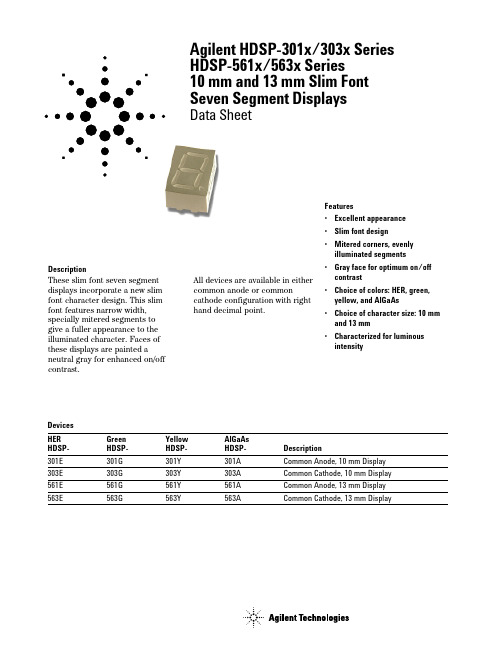
DescriptionThese slim font seven segment displays incorporate a new slim font character design. This slim font features narrow width,specially mitered segments to give a fuller appearance to the illuminated character. Faces of these displays are painted aneutral gray for enhanced on/off contrast.Agilent HDSP-301x/303x Series HDSP-561x/563x Series 10 mm and 13 mm Slim Font Seven Segment DisplaysData SheetFeatures•Excellent appearance •Slim font design •Mitered corners, evenly illuminated segments•Gray face for optimum on/off contrast •Choice of colors: HER, green,yellow, and AlGaAs •Choice of character size: 10 mm and 13 mm •Characterized for luminous intensityDevices HER Green Yellow AlGaAs HDSP-HDSP-HDSP-HDSP-Description301E 301G 301Y 301A Common Anode, 10 mm Display 303E 303G 303Y 303A Common Cathode, 10 mm Display 561E 561G 561Y 561A Common Anode, 13 mm Display 563E563G563Y563ACommon Cathode, 13 mm DisplayAll devices are available in either common anode or commoncathode configuration with righthand decimal point.Part Numbering System5082- x xx x-x x x xxHDSP- x xx x-x x x xxMechanical Options[1]00: No Mechanical OptionColor Bin Options[1,2]0: No Color Bin LimitationMaximum Intensity Bin[1,2]0: No Maximum Intensity Bin LimitationMinimum Intensity Bin[1,2]0: No Minimum Intensity Bin LimitationDevice Configuration/Color[1]A: AlGaAs RedE: High Efficiency RedG: GreenY: YellowDevice Specific Configuration[1]Refer to Respective Data SheetPackage[1]Refer to Respective Data SheetNotes:1. For codes not listed in the figure above, please refer to the respective data sheet or contact your nearest Agilent representativefor details.2. Bin options refer to shippable bins for a part-number. Color and Intensity Binbs are typically restricted to 1 bin per tube(exceptions may apply). Please refer to respective data sheet for specific bin limit information.Pin Function1G2F3Common A/C 4E5D6DP7C8Common A/C 9B10A7.006.40NOTE: QDSP-399G DOES NOT HAVE PIN 6.COUNTRY TOP SIDEFRONT VIEW RIGHT SIDE0.30 ± 0.05(0.012)6.001.85Pin Function 1E 2D3Common A/C 4C 5DP 6B 7A8Common A/C 9F 10G0.29 ± 0.08 TYP.(0.011)12345(0.023)(0.141)(0.100)NOTES:1. ALL DIMENSIONS ARE IN MILLIMETERS (INCHES).2. UNLESS OTHERWISE STATED, TOLERANCES ARE ±0.25 mm.Absolute Maximum RatingsDescription HER Green Yellow AlGaAs Units Average Power per Segment or DP10510510537mW Peak Forward Current per Segment or DP90909045mA DC Forward Current per Segment or DP30303015mA Operating Temperature Range–40 to +80–40 to +80–40 to +80–20 to +80˚C Storage Temperature Range–40 to +80–40 to +80–40 to +80–40 to +80˚C Reverse Voltage per Segment or DP5555V Wavesoldering Temperature for 3 Seconds250250250250˚C 1.59 mm below bodyNotes:1.Derate above 33˚C at 0.34 mA/˚C for HER.2.Derate above 27˚C at 0.32 mA/˚C for Green.3.Derate above 30˚C at 0.33 mA/˚C for Yellow.4.Derate above 60˚C at 0.25 mA/˚C for AlGaAs.Electrical/Optical Characteristics at T A = 25˚CHERDeviceSeriesHDSP-Parameter Symbol Min.Typ.Max.Units Test Conditions 301/303E Luminous Intensity/Segment I V 1.251 2.000mcd I F = 10 mA (Digit Average)Forward Voltage/Segment V F 1.90 2.50V I F = 20 mAor DPPeak WavelengthλPEAK635nm I F = 20 mADominant Wavelengthλd625nm I F = 20 mAReverse Current I R100µA V R = 5 VThermal Resistance LED RθJ–PIN351.5˚C/W/Seg.Junction-to-PinHERDeviceSeriesHDSP-Parameter Symbol Min.Typ.Max.Units Test Conditions 561/563E Luminous Intensity/Segment I V 2.001 3.526mcd I F = 10 mA (Digit Average)Forward Voltage/Segment V F 1.90 2.50V I F = 20 mAor DPPeak WavelengthλPEAK635nm I F = 20 mADominant Wavelengthλd625nm I F = 20 mAReverse Current I R100µA V R = 5 VThermal Resistance LED RθJ–PIN351.5˚C/W/Seg.Junction-to-PinDeviceSeriesHDSP-Parameter Symbol Min.Typ.Max.Units Test Conditions 301/303G Luminous Intensity/Segment I V 2.001 3.200mcd I F = 10 mA (digit average)Forward Voltage/Segment V F 2.25 2.50V I F = 20 mAor DPPeak WavelengthλPEAK568nm I F = 20 mADominant Wavelengthλd573nm I F = 20 mAReverse Current I R100µA V R = 5 VThermal Resistance LED RθJ–PIN351.5˚C/W/Seg.Junction-to-PinGreenDeviceSeriesHDSP-Parameter Symbol Min.Typ.Max.Units Test Conditions 561/563G Luminous Intensity/Segment I V 3.201 5.601mcd I F = 10 mA (Digit Average)Forward Voltage/Segment V F 2.25 2.50V I F = 20 mAor DPPeak WavelengthλPEAK568nm I F = 20 mADominant Wavelengthλd573nm I F = 20 mAReverse Current I R100µA V R = 5 VThermal Resistance LED RθJ–PIN351.5˚C/W/Seg.Junction-to-PinYellowDeviceSeriesHDSP-Parameter Symbol Min.Typ.Max.Units Test Conditions 301/303Y Luminous Intensity/Segment I V 1.251 2.000mcd I F = 10 mA (Digit Average)Forward Voltage/Segment V F 2.15 2.50V I F = 20 mAor DPPeak WavelengthλPEAK589nm I F = 20 mADominant Wavelengthλd590nm I F = 20 mAReverse Current I R100µA V R = 5 VThermal Resistance LED RθJ–PIN351.5˚C/W/Seg.Junction-to-PinDeviceSeriesHDSP-Parameter Symbol Min.Typ.Max.Units Test Conditions 561/563Y Luminous Intensity/Segment I V 2.00 3.526mcd I F = 10 mA (Digit Average)Forward Voltage/Segment V F 2.15 2.50V I F = 20 mAor DPPeak WavelengthλPEAK589nm I F = 20 mADominant Wavelengthλd590nm I F = 20 mAReverse Current I R100µA V R = 5 VThermal Resistance LED RθJ–PIN351.5˚C/W/Seg.Junction-to-PinNotes:1.Typical specification for reference only. Do not exceed absolute maximum ratings.2.The dominant wavelength, λ, is derived from the CIE chromaticity diagram and is that single wavelength which defines the color of the device.AlGaAsDeviceSeriesHDSP-Parameter Symbol Min.Typ.Max.Units Test Conditions 301/303A Luminous Intensity/Segment I V0.3200.505mcd I F = 1 mA (Digit Average)Forward Voltage/Segment V F 1.80 2.20V I F = 20 mAor DPPeak WavelengthλPEAK660nm I F = 20 mADominant Wavelengthλd643nm I F = 20 mAReverse Current I R100µA V R = 5 VThermal Resistance LED RθJ–PIN351.5˚C/W/Seg.Junction-to-PinAlGaAsDeviceSeriesHDSP-Parameter Symbol Min.Typ.Max.Units Test Conditions 561/563A Luminous Intensity/Segment I V0.5060.878mcd I F = 1 mA (Digit Average)Forward Voltage/Segment V F 1.80 2.20V I F = 20 mAor DPPeak WavelengthλPEAK660nm I F = 20 mADominant Wavelengthλd643nm I F = 20 mAReverse Current I R100µA V R = 5 VThermal Resistance LED RθJ–PIN351.5˚C/W/Seg.Junction-to-PinNotes:1.Typical specification for reference only. Do not exceed absolute maximum ratings.2.The dominant wavelength, λ, is derived from the CIE chromaticity diagram and is that single wavelength which defines the color of the device.HDSP-301E/303E/561E/563EIV Bin Category Min.Max.I 1.100 2.200K 1.800 3.600HDSP-561Y/563Y IV Bin Category Min.Max.K 1.800 3.600L 2.8005.600HDSP-301Y/303YIV Bin Category Min.Max.I 1.100 2.200K 1.8003.600HDSP-301A/303A/561A/563AIV Bin Category Min.Max.F 0.2800.560G 0.4500.900HDSP-301G/303G/561G/563GIV Bin Category Min.Max.K 1.800 3.600L 2.800 5.600Intensity Bin Limits (mcd)GreenYellowHERAlGaAs RedDominant Wavelength (nm)ColorBin Min.Max.Green 3570.00574.504567.00571.50Yellow2586.50590.003584.00587.50Color CategoriesNote:1. All categories are established for classification of products.Products may not be available in all categories. Please contact your Agilent representatives for further clarification/information.YellowFigure 1. Maximum allowable DC current vs.ambient temperature.Figure 2. Forward current vs. forward voltage.Figure 3. Relative luminous intensity vs. DC forward current.HDSP-301x/303x SeriesContrast EnhancementFor information on contrast enhancement, please see Application Note 1015.Soldering/CleaningCleaning agents from the ketone family (acetone, methyl ethyl ketone, etc.) and from thechlorinated hydrocarbon family (methylene chloride,Figure 4. Maximum allowable DC current vs.ambient temperature.Figure 5. Forward current vs. forward voltage.Figure 6. Relative luminous intensity vs. DC forward current.HDSP-561x/563x SeriesI D C – M A X I M U M D C C U R R E N T P E R S E G M E N T – m AT A – AMBIENT TEMPERATURE – °CI F – F O R W A R D C U R R E N TP E R S E G M E N T – m AV F – FORWARD VOLTAGE – V I D C – M A X I M U M D C C U R R E N T P E R S E G M E N T – m AT A – AMBIENT TEMPERATURE – °CI F – F O R W A R D C U R R E N TP E R S E G M E N T – m AV F – FORWARD VOLTAGE – V trichloroethylene, carbon tetrachloride, etc.) are notrecommended for cleaning LED parts. All of these varioussolvents attack or dissolve the encapsulating epoxies used to form the package of plastic LED parts.For information on soldering LEDs, please refer to Application Note 1027.R E L A T I V E L U M I N O U S I N T E N S I T Y (N O R M A L I Z E D T O 1 A T 5 m A F O R H E R A N D Y E L L O W A N D T O 1 A T 10 m A F O R G R E E N )I F – DC FORWARD CURRENT – mA12682410R E L A T I V E L U M I N O U S I N T E N S I T Y (N O R M A L I Z E D T O 1 A T 5 m A F O R H E R A N D Y E L L O W A N D T O 1 A T 10 m A F O R G R E E N )I F – DC FORWARD CURRENT – mA/semiconduc-torsFor product information and a complete list of distributors, please go to our web site.For technical assistance call:Americas/Canada: +1 (800) 235-0312 or (916) 788-6763Europe: +49 (0) 6441 92460China: 10800 650 0017Hong Kong: (+65) 6756 2394India, Australia, New Zealand: (+65) 6755 1939 Japan: (+81 3) 3335-8152(Domestic/ International), or 0120-61-1280(Domestic Only) Korea: (+65) 6755 1989Singapore, Malaysia, Vietnam, Thailand, Philippines, Indonesia: (+65) 6755 2044 Taiwan: (+65) 6755 1843Data subject to change.Obsoletes 5980-2919ENJuly 11, 20045988-4352EN。
海德能膜产品技术手册
目录第一章美国海德能公司RO/NF膜产品规格与性能第二章反渗透及纳滤膜应用技术介绍第三章反渗透、纳滤基础知识第四章水化学与水质分析第五章预处理第六章反渗透系统设计第七章反渗透膜的安装及运行第八章污染与清洗第九章RO/NF系统故障诊断和排除第十章海德能公司反渗透膜元件质量保证书第十一章海德能公司退货程序(RGA)第十二章反渗透技术问答第十三章应用技术文献第一章美国海德能公司RO/NF膜产品规格与性能1.1 8英寸膜元件端板新型涡旋切1。
2 流式设计美国海德能公司已于2002年12月12日正式推出针对所有标准的 8 英寸膜元件端板的新型涡旋切流式(以下简称为“切流式”)设计。
这一新的密封支撑/防止膜卷突出设计(ATD)提供了更好的端面接触,使水力负荷分布的更加均匀.新的切流式设计保持了海德能公司产品多孔端板的特点,该端板可以保护膜元件免受因较大颗粒撞击而造成的损坏。
这一特殊的涡旋式图案设计使得穿过膜元件表面的水具有均匀的分布,并可以平衡膜元件外部和中心管的压力。
新的切流式可以很容易地由其象牙色和涡旋式结构辨认,而不同于以前的灰色和直线式。
同时,我们还将介绍新型内连接管,它即适用于新型切流式膜元件,也适用于传统的海德能膜元件.新型内连接管具有很多好处,在负载和操作过程中不会脱离。
新型切流式膜元件完全与工业市场中众多其它的膜元件相兼容。
海德能公司正致力于膜元件内部密封方法的研究,以提供压力容器中膜元件之间密封连接的最大保证。
目前正使用的非切流式膜元件设计可以允许内部和外部的密封。
海德能公司在持续不断地为我们的用户研究和开发创新的、改进性的产品。
新切流设计在保持水通量和脱盐率的一致性及可靠性的基础上提供了附加的益处。
海德能公司正在以改进的设计模式,在无附加成本的情况下,一同既往地生产高质量的膜产品。
技术说明—新型切流式膜元件需使用内连接管- 每支新型切流式膜元件的包装中均装备一支内连接管- SWC 系列内连接管部件号码不同于其它苦咸水反渗透膜产品的内连接管部件号码—新切流式膜元件不能使用外连接管和外连接型端板接头—新型内连接管同时适用于新型切流式和传统膜元件—新切流式设计膜元件与市售的大多数公司的膜元件的连接管和端板接头完全兼容—标准中心管内径为1。
微冷-抗静电电路冷却剂, 安全技术说明书

化学品安全技术说明书FRZA - ANTI-STATIC CIRCUIT CHILLER, AEROSOL符合GB/T 16483-2008和GB/T 17519-2013规定化学品标识产品名称FRZA - ANTI-STATIC CIRCUIT CHILLER, AEROSOL产品编号MCC-FRZA别名,商品名"FRZA - Anti-Stat Micro Freeze"化学品的推荐用途和限制用途限制用途没有辨识出特定的禁止用途。
供应商的详细情况供应商MICROCARE ASIA PTE LTD102E, Pasir Panjang Road,Citilink, #05-06,Singapore 118529(65)6271.0182制造商MICROCARE LLC595 John Downey DriveNew Britain, CT 06051United States of AmericaCAGE: OATV9Tel: +1 800-638-0125, +1 860-827-0626应急咨询电话应急咨询电话INFOTRAC 4001-200761 (CHINA)1-352-323-3500 (from anywhere in the world)紧急情况概述外观液体。
气体 气溶胶。
颜色无色的。
气味轻微的。
乙醚。
GHS 危险性类别物理危险气溶胶 类别3健康危害非此类环境危害非此类健康危害接触液化气体后会引起冻伤,在有些情况下会损伤组织器官。
长期或反复与皮肤接触可能会引起刺激、皮肤红肿和皮炎。
轻度皮炎、过敏性皮疹。
物理危险 蒸气比空气重,可能沿地面传播并积聚在容器的底部。
气体或蒸气取代可供呼吸的氧气(窒息剂)。
由于使用量小,不被认为是一种重大危险源。
标签要素警示词警告危险性说明H229 压力容器:遇热可爆。
防范说明预防措施P210 远离热源/ 热表面/ 火花/明火/ 其他点火源。
beta-Ionone R BMBcert 安全技术说明书
安全技术说明书页: 1/12 巴斯夫安全技术说明书按照GB/T 16483编制日期 / 本次修订: 06.09.2022版本: 11.0日期/上次修订: 18.12.2021上次版本: 10.1日期 / 首次编制: 29.11.2005产品: beta-Ionone R BMBcert™(30785404/SDS_GEN_CN/ZH)印刷日期 18.10.20231. 化学品及企业标识beta-Ionone R BMBcert™推荐用途和限制用途: 化学品, 清洁剂用化学品, 化妆和口腔护理化学品, 调味品公司:巴斯夫(中国)有限公司中国上海浦东江心沙路300号邮政编码 200137电话: +86 21 20391000传真号: +86 21 20394800E-mail地址: **********************紧急联络信息:巴斯夫紧急热线中心(中国)+86 21 5861-1199巴斯夫紧急热线中心(国际):电话: +49 180 2273-112Company:BASF (China) Co., Ltd.300 Jiang Xin Sha RoadPu Dong Shanghai 200137, CHINA Telephone: +86 21 20391000Telefax number: +86 21 20394800E-mail address: ********************** Emergency information:Emergency Call Center (China):+86 21 5861-1199International emergency number: Telephone: +49 180 2273-1122. 危险性概述纯物质和混合物的分类:对水环境的急性危害: 分类2对水环境的慢性危害: 分类2巴斯夫安全技术说明书日期 / 本次修订: 06.09.2022版本: 11.0产品: beta-Ionone R BMBcert™(30785404/SDS_GEN_CN/ZH)印刷日期 18.10.2023标签要素和警示性说明:图形符号:危险性说明:H401对水生生物有毒。
特瑞堡中文泛塞密封

2
特康® 泛塞®
■ 概述
特康® 泛塞® 是一种单作用,弹簧施力的密封件,用于 动态和静态运动。
泛塞® 在广泛的应用中是十分有效的。适用于要求具有 较好的耐化学介质的性能时,或者要求密封件工作在 极端温度下,以及用于需要良好的挤压和压缩性能的 场合。
最新资料请访问 2008年5月版
1
特康® 泛塞®
■ 选择正确的密封件
特康® 泛塞® 在所有工业领域的诸如液压缸和气缸之类 的元件设计中提供非常重要的作用,包括: - 极好的密封性能 - 非常耐磨损 - 抗间隙挤出性好 - 良好的耐腐蚀和耐磨性能 - 非常好的温度性能 - 摩擦系数小 - 结构紧凑 - 安装简单 特康® 泛塞® 有各种几何形状和结构,允许针对每种用 途选择最佳的形状。它们能够由各种特康® 材料(我们 的专利PTFE基复合物)制成,这些复合物是专门针对 密封件的配方,并且提供上乘的特性,专门满足我们 客户的要求。 当需要时,也能够用佐康® 材料(我们的专利聚乙烯基 复合物)制成。 为了针对您的用途,选择最好的特康® 泛塞® ,您必须 首先确定功能参数,第4页的表I和表II,以及第5页的 表III则能够用来对密封件和材料进行初选。这些表中详 细给出了在样本的何处能够找到进一步的细节。 考虑配合面的质量也是重要的,它对密封系统的使用 寿命和功能有重大的影响,有关这方面的指南在13页 和14页给出。 如果就有关密封件的技术规格需要帮助,请联系特瑞 堡密封系统公司,可以找您当地的市场部门,或登陆
下面列出泛塞在高达15ms49英尺s的速度下能够密封能够承受200mpa2000bar29000psi以上的高压能够安装在符合milg5514f和din3771的沟槽中弹簧力系统压力varisealvariseal选择表动态mpabapsi静态mpabapsim215454506527606008702709426050015m2s1645450652760600870270942605001005t40202002900606008702709423044615404005801808001160312018426050001t05hf28404005801808001160320032826050001t05roto2815150217525250362510014826050010c满足表ii外套材料选择指南turcont05turcont24turcont24turcont40turcont40turcont01zurconz80turcont78turcont01turcont01最新资料请访问wwwtsstrelleborgcom2008年5月版密封件接触的介质或工作条件静态或稍微动态往复旋转技术数据用途材料型式页码最高压力用途的类型工作温度最高速度标准材料空气气体水蒸气油原油普通化学品石油化学品食品药品真空材料选择指南t012500mm2500mm2500mm2500mm2500mm2500mm2500mm2500mm特殊材料适合较高的辐射负载有关这方面的进一步详细资料请联系特瑞堡密封系统公司
Fiat50180标准中文版
Fiat汽车标准50180——腐蚀性试验1. 综述该标准含盖了以下盐雾试验的流程(时间、大气环境及试验装置):-方法A1——盐雾喷射试验-方法A2——乙酸-盐雾喷射试验-方法A3——铜-加速乙酸盐雾喷射试验-方法B1——在划格试样表皮下的盐雾喷射耐腐蚀性试验-方法B2——冲压(碎石)后插件式皮下耐腐蚀性试验-方法C1——酸溶液浸泡耐腐蚀性试验-方法C2——碱溶液浸泡耐腐蚀性试验-方法C3——铜加速乙酸盐雾溶液浸泡耐腐蚀性试验-方法D1——(工业环境下的)耐腐蚀性试验-方法D2——(在浓度减少的工业大气环境下的)耐腐蚀性试验-方法D3——在强制通风的工业大气环境下的耐腐蚀性试验1.2目的这些标准化试验为车身材料、涂层、零件及组件在腐蚀性环境下的影响提供了一个模拟的加速方法1.3范围-方法A1——针对金属材料以及各类有机、无机、化学及电解涂层-方法A2——适用于那些只有轻微反应的无机化学涂层及电解涂层(例如钢基或锌合金上镀铬、铝基上阳极氧化等)-方法A3——针对与方法A2相同的涂层,但该方法的腐蚀速度大约高出方法A2的5倍-方法B1和B2——针对有机涂层-方法C1——针对排气消声器-方法C2和C3——适合用在高真空升华及冷凝作用所产生的金属光泽涂层-方法D1——针对金属材料和无机、化学及电解涂层-方法D2——针对有机涂层-方法D3——针对板料上的防护油涂层、冲压的润滑油以及冲压后所使用的防护产品除了上述要求,试验类型的选择还应根据材料、涂层、零件或组件在维护期间的曝露条件以及可能接触的腐蚀剂的化学成分2. 试验方法的原理2.1方法A1、A2、A3、C2、C3、D1、D2和D3这些方法是根据在给出的时间以及腐蚀剂的作用下,在待测表面上所形成的不同颜色或外观的痕迹或斑点而形成的2.2方法B1和B2这些方法是基于对曝露前形成的切口线或冲切点以外区域的腐蚀性传播(涂层皮下膜)的评估2.3方法C1该方法是基于对经腐蚀剂浸泡后,待测表面的质量损失所做出的测量3. 试验条件的分类基于试验条件,环境测试在车辆维护过程中模拟出可能遭遇的不同强度影响,按照严重度等级进行分类3.1参数每次腐蚀性测试的严重度等级对下列参数将起到作用:-所选用的腐蚀剂浓度(仅针对方法D3)-所选用的腐蚀性程度-测试持续时间除非相关标准上另有规定,否则应遵循以下章节所制定的条件,以建立每次测试的严重度等级3.1.1所选用的腐蚀剂浓度(仅针对方法D3)(略)3.1.2试剂的腐蚀等级既然所选择试剂的腐蚀等级不仅仅取决于其化学成分(参看段落6),还取决于与其相互反应的材料或涂层,因此就不可能在此标准中对试剂的腐蚀等级进行划分。
危险化学品特性表_第6类 有毒品
目录表- 氰化钠的理化性质及危险特性 (1)表- 氰化钾的理化性质及危险特性 (2)表- 氰化铜的理化性质及危险特性 (3)表- 氰化银的理化性质及危险特性 (4)表- 氰化锌的理化性质及危险特性 (5)表- 氰化金钾的理化性质及危险特性 (6)表- 三氧化(二)砷的理化性质及危险特性 (7)表- 碳酸钡的理化性质及危险特性 (8)表- 氯化钡的理化性质及危险特性表 (9)表- 氢氧化钡的理化性质及危险特性表 (10)表- 环氧氯丙烷的理化性质和危险特性表 (11)表- 硝基苯的理化性质和危险特性表 (12)表- 氯化苄的理化性质和危险特性表 (13)表- 二氯化苄的理化性质及危险特性 (14)表- 苯酚的理化性质及危险特性表 (15)表- 邻甲(苯)酚的理化性质及危险特性 (16)表- N,N-二甲(基)苯胺的理化性质和危险特性表 (17)表- 甲苯-2,4-二异氰酸酯的理化性质及危险特性表 (18)表- 六亚甲基二异氰酸酯的理化性质及危险特性 (19)表- 己酮肟威的理化性质及危险特性表 (20)表- 灭害威的理化性质及危险特性表 (21)表- 克百威[含量>10%]的理化性质及危险特性表 (22)表- 自克威[含量>25%]的理化性质及危险特性表 (23)表- 间异丙威的理化性质及危险特性表 (24)表- 杀线威的理化性质及危险特性表 (25)表- 敌蝇威[含量>50%]的理化性质及危险特性表 (26)表- 涕灭威的理化性质及危险特性表 (27)表- 腈叉威的理化性质及危险特性表 (28)表- 恶虫威[含量>65%]的理化性质及危险特性表 (29)表- 异索威[含量>20%]的理化性质及危险特性表 (30)表- 硒粉的理化性质及危险特性 (31)表- 氧化钡的理化性质及危险特性表 (32)表- 一氧化铅的理化性质和危险特性表 (33)表- 四氧化(三)铅的理化性质和危险特性表 (34)表- 硫酸汞的理化性质和危险特性表 (35)表- 硝酸亚汞的理化性质和危险特性表 (36)表- 氟化铵的理化性质及危险特性表 (37)表- 氟化钠的理化性质及危险特性 (38)表- 氟化钾的理化性质及危险特性 (39)表- 氟化钡的理化性质及危险特性 (40)表- 氟硅酸钠的理化性质和危险特性表 (41)表- 氟锆酸钾的理化性质及危险特性 (42)表- 硫酸铜的理化性质及危险特性表 (43)表- 三氯甲烷的理化性质及危险特性表 (45)表- 四氯化碳的理化性质及危险特性 (46)表- 1,1,1-三氯乙烷的理化性质及危险特性表 (47)表1,1,2-三氯乙烷的理化性质及危险特性表 (48)表- 1,1,2,2-四氯乙烷的理化性质和危险特性表 (49)表- 溴代乙烷的理化性质和危险特性表 (50)表- 三氯乙烯的理化性质及危险特性表 (51)表- 四氯乙烯的理化性质及危险特性表 (52)表- 十二硫醇的理化性质和危险特性表 (53)表- 乙二醇丁醚的理化性质及危险特性表 (54)表- 水杨醛的理化性质和危险特性表 (55)表- 二苯甲烷-4,4’-二异氰酸酯的理化性质及危险特性 (56)表- 异佛尔酮二异氰酸酯的理化性质及危险特性表 (57)表- 邻二氯苯的理化性质和危险特性表 (58)表- 3,4-二氯苄基氯的理化性质及危险特性 (59)表- 对甲苯磺酰氯的理化性质和危险特性表 (60)表- 邻硝基(苯)酚的理化性质和危险特性表 (61)表- 对硝基(苯)酚的理化性质和危险特性表 (62)表- 邻氨基(苯)酚的理化性质和危险特性表 (63)表- 间氨基(苯)酚的理化性质和危险特性表 (64)表- 对氨基(苯)酚的理化性质和危险特性表 (65)表- 间苯二酚的理化性质和危险特性表 (67)表- 对苯二酚的理化性质及危险特性表 (68)表- 间苯三酚的理化性质和危险特性表 (69)表- 丙烯酰胺的理化性质及危险特性表 (70)表- 苯胺的理化性质和危险特性表 (71)表- 邻苯二胺的理化性质和危险特性表 (72)表- 间苯二胺的理化性质和危险特性表 (73)表- 对苯二胺的理化性质和危险特性表 (74)表- 苯肼的理化性质和危险特性表 (75)表- 硫脲的理化性质及危险特性表 (76)表- 苯醌的理化性质及危险特性表 (77)表- α-萘乙酸的理化性质和危险特性表 (78)表- α-萘胺的理化性质和危险特性表 (79)表- 盐酸-1-萘乙二胺的理化性质和危险特性表 (80)表- 喹啉的理化性质和危险特性表 (81)表- 乙酸铅的理化性质和危险特性表 (82)表- 酒石酸锑钾的理化性质和危险特性表 (83)表- 二丁基二月桂酸锡的理化性质和危险特性表 (84)表- 辛酸亚锡的理化性质和危险特性表 (85)表- 三苯(基)磷的理化性质及危险特性表 (86)表- 煤焦沥青的理化性质及危险特性 (87)表- 2,4-滴[含量>75%]的理化性质和危险特性表 (88)表- 1,2,2-三氯三氟乙烷的理化性质及危险特性 (89)表-氰化金钾的理化性质及危险特性表-三氧化(二)砷的理化性质及危险特性表-碳酸钡的理化性质及危险特性表-氯化钡的理化性质及危险特性表表- 氢氧化钡的理化性质及危险特性表表-环氧氯丙烷的理化性质和危险特性表表-邻甲(苯)酚的理化性质及危险特性表-N,N-二甲(基)苯胺的理化性质和危险特性表表-甲苯-2,4-二异氰酸酯的理化性质及危险特性表表-六亚甲基二异氰酸酯的理化性质及危险特性表-己酮肟威的理化性质及危险特性表表-灭害威的理化性质及危险特性表表-间异丙威的理化性质及危险特性表表-杀线威的理化性质及危险特性表表-敌蝇威[含量>50%]的理化性质及危险特性表表-硒粉的理化性质及危险特性表-四氧化(三)铅的理化性质和危险特性表表-硫酸汞的理化性质和危险特性表表-硝酸亚汞的理化性质和危险特性表表-氟硅酸钠的理化性质和危险特性表表-二氯甲烷的理化性质及危险特性表-三氯甲烷的理化性质及危险特性表。
危险化学品特性表_第8类腐蚀品

危险化学品特性表_第8类腐蚀品work Information Technology Company.2020YEAR目录8.1类酸性腐蚀品发烟硝酸的理化性质和危险特性(表-) (1)硝酸的理化性质及危险特性(表-) (2)发烟硫酸的理化性质及危险特性(表-) (3)硫酸的理化性质及危险特性(表-) (4)亚硫酸的理化性质和危险特性(表-) (5)盐酸的理化性质及危险特性(表-) (6)氢氟酸的理化性质及危险特性(表-) (7)氢溴酸的理化性质和危险特性(表-) (8)溴水的理化性质及危险特性(表-) (9)氟硅酸的理化性质及危险特性(表-) (10)氟硼酸的理化性质及危险特性(表-) (11)氯化亚砜的理化性质和危险特性(表-) (12)三氯化铝的理化性质及危险特性(表-) (14)三氯化锑的理化性质和危险特性(表-) (15)四氯化钛的理化性质和危险特性(表-) (16)五氧化(二)磷的理化性质和危险特性(表-) (17)甲酸的理化性质及危险特性(表-) (18)三氟乙酸的理化性质和危险特性(表-) (19)苯酚磺酸的理化性质及危险特性(表-) (20)苯甲酰氯的理化性质及危险特性(表-) (21)苯磺酰氯的理化性质和危险特性(表-) (22)正磷酸的理化性质及危险特性(表-) (23)亚磷酸的理化性质和危险特性(表-) (24)多聚磷酸的理化性质和危险特性(表-) (25)氨基磺酸的理化性质及危险特性(表-) (26)氯铂酸的理化性质和危险特性(表-) (27)硫酸羟胺的理化性质和危险特性(表-) (28)硫酸氢钾的理化性质和危险特性(表-) (29)亚硫酸氢钠的理化性质和危险特性(表-) (30)三氯化铝溶液的理化性质及危险特性(表-) (31)硫酸镁的理化性质及危险特性(表-) (33)三氯化铁的理化性质及危险特性(表-) (34)三氯化铁溶液的理化性质及危险特性(表-) (35)三氯化碘的理化性质和危险特性(表-) (36)乙酸的理化性质及危险特性(表-) (37)乙酸溶液的理化性质及危险特性(表-) (38)醋酐的理化性质及危险特性(表-) (39)三氯乙酸的理化性质及危险特性(表-) (40)丙烯酸的理化性质及危险特性(表-) (41)甲基丙烯酸的理化性质及危险特性(表-) (42)丁酸的理化性质和危险特性(表-) (43)丁烯二酸酐的理化性质及危险特性(表-) (44)甲(基)磺酸的理化性质和危险特性(表-) (45)邻苯二甲酸酐的理化性质及危险特性(表-) (46)四氢酞酐的理化性质及危险特性(表-) (47)8.2 类碱性腐蚀品氢氧化钠的理化性质及危险特性(表-) (48)氢氧化钠溶液的理化性质及危险特性(表-) (49)氢氧化钾的理化性质及危险特性(表-) (50)氢氧化钾溶液的理化性质及危险特性(表-) (51)氢氧化锂的理化性质和危险特性(表-) (52)硫化钠的理化性质及危险特性(表-) (53)乙醇钠的理化性质和危险特性(表-) (54)四甲基氢氧化铵的理化性质及危险特性(表-) (56)水合肼[含肼≤64%]的理化性质及危险特性(表-) (57)环已胺的理化性质及危险特性(表-) (58)二亚乙基三胺的理化性质和危险特性(表-) (59)三亚乙基四胺的理化性质及危险特性(表-) (60)二(正)丁胺的理化性质及危险特性(表-) (61)1,2-乙二胺的理化性质及危险特性(表-) (62)1,6-己二胺的理化性质和危险特性(表-) (63)钠石灰[含氢氧化钠>4%]的理化性质和危险特性(表-) (64)氨水的理化性质及危险特性(表-) (65)1-氨基乙醇的理化性质及危险特性(表-) (66)乙醇胺的理化性质及危险特性(表-) (67)二乙醇胺的理化性质及危险特性(表-) (68)异佛尔酮二胺的理化性质及危险特性(表-) (69)哌嗪的理化性质及危险特性(表-) (70)8.3 类其他腐蚀品氟化氢铵的理化性质及危险特性(表-) (71)氟化氢钾的理化性质及危险特性(表-) (72)三氟化硼乙醚络合物的理化性质和危险特性(表-) (73)甲醛溶液的理化性质及危险特性(表-) (74)次氯酸钠溶液的理化性质及危险特性(表-) (75)氯化铜的理化性质和危险特性(表-) (76)氯化锌的理化性质和危险特性(表-) (77)汞的理化性质及危险特性(表-) (78)原料(非危险化学品)的理化性能表(表-) (79)发烟硝酸的理化性质和危险特性(表-)硝酸的理化性质及危险特性(表-)发烟硫酸的理化性质及危险特性(表-)硫酸的理化性质及危险特性(表-)亚硫酸的理化性质和危险特性(表-)盐酸的理化性质及危险特性(表-)氢氟酸的理化性质及危险特性(表-)氢溴酸的理化性质和危险特性(表-)溴水的理化性质及危险特性(表-)氟硅酸的理化性质及危险特性(表-)氟硼酸的理化性质及危险特性(表-)氯化亚砜的理化性质和危险特性(表-)四氯化钛的理化性质和危险特性(表-)五氧化(二)磷的理化性质和危险特性(表-)甲酸的理化性质及危险特性(表-)三氟乙酸的理化性质和危险特性(表-)苯酚磺酸的理化性质及危险特性(表-)苯甲酰氯的理化性质及危险特性(表-)苯磺酰氯的理化性质和危险特性(表-)正磷酸的理化性质及危险特性(表-)亚磷酸的理化性质和危险特性(表-)多聚磷酸的理化性质和危险特性(表-)氨基磺酸的理化性质及危险特性(表-)氯铂酸的理化性质和危险特性(表-)硫酸羟胺的理化性质和危险特性(表-)硫酸氢钾的理化性质和危险特性(表-)亚硫酸氢钠的理化性质和危险特性(表-)三氯化铝溶液的理化性质及危险特性(表-)硫酸镁的理化性质及危险特性(表-)三氯化铁的理化性质及危险特性(表-)三氯化铁溶液的理化性质及危险特性(表-)三氯化碘的理化性质和危险特性(表-)乙酸的理化性质及危险特性(表-)乙酸溶液的理化性质及危险特性(表-)醋酐的理化性质及危险特性(表-)三氯乙酸的理化性质及危险特性(表-)丙烯酸的理化性质及危险特性(表-)甲基丙烯酸的理化性质及危险特性(表-)丁酸的理化性质和危险特性(表-)丁烯二酸酐的理化性质及危险特性(表-)甲(基)磺酸的理化性质和危险特性(表-)。
若丁50-MSDS
身体防护:
穿防毒物渗透工作服。
手防护:
戴橡胶手套。
其他防护:
工作现场禁止吸烟、进食和饮水。工作完毕,淋浴更衣。保持良好的卫生习惯。
外观与性状:
暗红色透明液体。
熔点(℃):
无资料
相对密度(水=1):
1.05
沸点(℃):
无资料
相对蒸气密度(空气=1):
无资料
饱和蒸气压(kPa):
无资料
第十六部分
其他信息
化学品中文名称:
若丁50
化学品俗名:
化学品英文名称:
Rodine50
英文名称:
有害物成分
含量
CAS No.
三嗪类
40-50%
68083-44-3
危险性类别:
Class 8 (UN 3265)
健康危害:
目前未见职业中毒的资料报道
燃爆危险:
无爆炸危险
皮肤接触:
脱去污染的衣着,用流动清水冲洗。
储存注意事项:
储存于阴凉、通风的库房。应与氧化剂分开存放,切忌混储。配备相应品种和数量的消防器材。储区应备有合适的材料收容泄漏物。
中国MAC(mg/m3):
未制定标准。
前苏联MAC(mg/m3):
未制定标准。
工程控制:
密闭操作,局部排风。
呼吸系统防护:
紧急事态抢救或撤离时,应该佩戴空气呼吸器。
眼睛防护:
亚急性和慢性毒性:
无资料
刺激性:
无资料
致敏性:
无资料
致突变性:
无资料
致畸性:
无资料
致癌性:
无资料
生态毒理毒性:
无资料
生物降解性:
V23072-A1061-A303中文资料
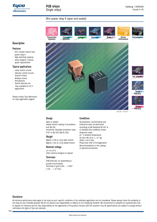
Indicator lamps Make Double contact/ make contact/ Form A Form U
Circuit symbol (see also Pin assignment)
4
Rated voltage Rated current at 85 °C Contact material Max. switching voltage/power Max. switching current1) On2) Off Min. recommended load5) Voltage drop at 10 A (initial) for NC/NO contacts Mechanical endurance (without load) Electrical endurance (example of resistive load)
Ø .512 +.004 (1.3 +0.1) .049 … .050 (1.25 … 1.27)
.094 ±.024 (2.4 ±0.6)
ECR0598-P
.106 ±.016 (2.7 ±0.4)
102
Please observe the disclaimer.
元器件交易网
View of the terminals (Bottom view)
.075 ±.008 (1.9 ±0.2) 2 x Ø .033 ±.002 (0.85 ±0.05) .181 ±.008 (4.6 ±0.2) Ø .079 ±.004 (Ø 2 ±0.1) .354 ±.008 (9 ±0.2) .033 ±.002 (0.85 ±0.06)
Weight
Approx. 0.28 oz. (8 g) open version Approx. 0.32 oz. (9 g) sealed version
A403A403M
Designation:A403/A403M–06Standard Specification forWrought Austenitic Stainless Steel Piping Fittings1This standard is issued under thefixed designation A403/A403M;the number immediately following the designation indicates the year of original adoption or,in the case of revision,the year of last revision.A number in parentheses indicates the year of last reapproval.A superscript epsilon(e)indicates an editorial change since the last revision or reapproval.This standard has been approved for use by agencies of the Department of Defense.1.Scope*1.1This specification covers wrought stainless steelfittings for pressure piping applications.21.2Several grades of austenitic stainless steel alloys are included in this specification Grades are designated with a prefix,WP or CR,based on the applicable ASME or MSS dimensional and rating standards,respectively.1.3For each of the WP stainless grades,several classes of fittings are covered,to indicate whether seamless or welded construction was utilized.Class designations are also utilized to indicate the nondestructive test method and extent of nondestructive examination(NDE).Table1is a general summary of thefitting classes applicable to all WP grades of stainless steel covered by this specification.There are no classes for the CR grades.Specific requirements are covered elsewhere.1.4This specification is expressed in both inch-pound units and in SI units.However,unless the order specifies the applicable“M”specification designation(SI units),the mate-rial shall be furnished to inch-pound units.1.5The values stated in either inch-pound units or SI units are to be regarded separately as standard.Within the text,the SI units are shown in brackets.The values stated in each system are not exact equivalents;therefore,each system must be used independently of the bining values from the two systems may result in nonconformance with the specifi-cation.1.6This specification does not apply to cast steelfittings. Austenitic stainless steel castings are covered in Specifications A351/A351M,A743/A743M,and A744/A744M.2.Referenced Documents2.1ASTM Standards:3A351/A351M Specification for Castings,Austenitic,for Pressure-Containing PartsA370Test Methods and Definitions for Mechanical Testing of Steel ProductsA480/A480M Specification for General Requirements for Flat-Rolled Stainless and Heat-Resisting Steel Plate, Sheet,and StripA743/A743M Specification for Castings,Iron-Chromium, Iron-Chromium-Nickel,Corrosion Resistant,for General ApplicationA744/A744M Specification for Castings,Iron-Chromium-Nickel,Corrosion Resistant,for Severe ServiceA751Test Methods,Practices,and Terminology for Chemical Analysis of Steel ProductsA960/A960M Specification for Common Requirements for Wrought Steel Piping FittingsE112Test Methods for Determining Average Grain Size E165Test Method for Liquid Penetrant Examination2.2ASME Standards:ASME B16.9Factory-Made Wrought Steel Butt-Welding Fittings4ASME B16.11Forged Steel Fittings,Socket-Welding and Threaded42.3MSS Standards:MSS SP-25Standard Marking System for Valves,Fittings, Flanges,and Unions5MSS SP-43Standard Practice for Light Weight Stainless Steel Butt-Welding Fittings51This specification is under the jurisdiction of ASTM Committee A01on Steel, Stainless Steel and Related Alloys and is the direct responsibility of Subcommittee A01.22on Steel Forgings and Wrought Fittings for Piping Applications and Bolting Materials for Piping and Special Purpose Applications.Current edition approved March1,2006.Published March2006.Originally approved st previous edition approved in2004as A403/A403M-04.2For ASME Boiler and Pressure Vessel Code applications see related Specifi-cation SA-403in Section II of that Code.3For referenced ASTM standards,visit the ASTM website,,or contact ASTM Customer Service at service@.For Annual Book of ASTM Standards volume information,refer to the standard’s Document Summary page on the ASTM website.4Available from American Society of Mechanical Engineers(ASME),ASME International Headquarters,Three Park Ave.,New York,NY10016-5990.5Available from Manufacturers Standardization Society of the Valve and Fittings Industry(MSS),127Park St.,NE,Vienna,V A22180-4602.*A Summary of Changes section appears at the end of this standard. Copyright©ASTM International,100Barr Harbor Drive,PO Box C700,West Conshohocken,PA19428-2959,United States.MSS SP-79Socket-Welding Reducer Inserts 52.4ASME Boiler and Pressure Vessel Code:Section VIII Division I,Pressure Vessels 4Section IX,Welding Qualifications 42.5AWS Standards:A 5.4Specification for Corrosion-Resisting Chromium and Chromium-Nickel Steel Covered Welding Electrodes 6A 5.9Specification for Corrosion-Resisting Chromium and Chromium-Nickel Steel Welding Rods and Bare Elec-trodes 62.6ASNT:SNT-TC-1A (1984)Recommended Practice for Nonde-structive Testing Personnel Qualification and Certifica-tion mon Requirements and Ordering Information 3.1Material furnished to this specification shall conform to the requirements of Specification A 960/A 960M including any supplementary requirements that are indicated in the purchase order.Failure to comply with the common requirements of Specification A 960/A 960M constitutes nonconformance with this specification.In case of conflict between this specification and Specification A 960/A 960M ,this specification shall pre-vail.3.2Specification A 960/A 960M identifies the ordering in-formation that should be complied with when purchasing material to this specification.4.Material4.1The material for fittings shall consist of forgings,bars,plates,or seamless or welded tubular products that conform to the chemical requirements in Table 2.See Table 3for a list of common names.4.2The steel shall be melted by one of the following processes:4.2.1Electric furnace (with separate degassing and refining optional),4.2.2Vacuum furnace,or4.2.3One of the former followed by vacuum or electroslag-consumable remelting.4.3If secondary melting is employed,the heat shall be defined as all ingots remelted from a primary heat.5.Manufacture5.1Forming —Forging or shaping operations may be per-formed by hammering,pressing,piercing,extruding,upsetting,rolling,bending,fusion welding,machining,or by a combina-tion of two or more of these operations.The forming procedure shall be so applied that it will not produce injurious defects in the fittings.5.2All fittings shall be heat treated in accordance with Section6.5.3Grade WP fittings ordered as Class S shall be of seamless construction and shall meet all requirements of ASME B16.9or MSS SP-79.5.4Grade WP fittings ordered as Class W shall meet the requirements of ASME B16.9and:5.4.1Shall have all pipe welds made by mill or the fitting manufacturer with the addition of filler metal radiographically examined throughout the entire length in accordance with the Code requirements stated in 5.5,and,5.4.2Radiographic inspection is not required on single longitudinal seam welds made by the starting pipe manufac-turer if made without the addition of filler metal;and5.4.3Radiographic inspection is not required on longitudi-nal seam fusion welds made by the fitting manufacturer when all of the following conditions have been met:5.4.3.1No addition of filler metal,5.4.3.2Only one welding pass per weld seam,and,5.4.3.3Fusion welding from one side only.5.4.4In place of radiographic examination,welds made by the fitting manufacturer may be ultrasonically examined in accordance with the Code requirements stated in 5.6.5.5Grade WP fittings ordered as Class WX shall meet the requirements of ASME B16.9and shall have all welds,whether made by the fitting manufacturer or the starting material manufacturer,radiographically examined throughout their entire length in accordance with Paragraph UW-51of Section VIII,Division I,of the ASME Boiler and Pressure Vessel Code .5.6Grade WP fittings ordered as Class WU shall meet the requirements of ASME B16.9and shall have all welds,whether made by the fitting manufacturer or the starting material manufacturer,ultrasonically examined throughout their entire length in accordance with Appendix 12of Section VIII,Division 1of ASME Boiler and Pressure Vessel Code .5.7The radiography or ultrasonic examination of welds for this class of fittings may be done at the option of the manufacturer,either prior to or after forming.5.8Personnel performing NDE examinations shall be quali-fied in accordance with SNT-TC-1A .5.9Grade CR fittings shall meet the requirements of MSS SP-43and do not require nondestructive examination.5.10All fittings shall have the welders,welding operators,and welding procedures qualified under the provisions of Section IX of the ASME Boiler and Pressure Vessel Code except that starting pipe welds made without the addition of filler metal do not require such qualification.5.11All joints welded with filler metal shall be finished in accordance with the requirements of Paragraph UW-35(a)of Section VIII,Division I,of the ASME Boiler and Pressure Vessel Code .6Available from American Welding Society (AWS),550NW LeJeune Rd.,Miami,FL 33126.7Available from American Society for Nondestructive Testing (ASNT),P.O.Box 28518,1711Arlingate Ln.,Columbus,OH 43228-0518.TABLE 1Fitting Classes for WP GradesClass Construction Nondestructive Examination S Seamless NoneW Welded Radiography or Ultrasonic WX Welded Radiography WUWeldedUltrasonic5.12Fittings machined from bar shall be restricted to NPS 4or smaller.Elbows,return bends,tees,and header tees shall not be machined directly from bar stock.5.12.1All caps machined from bar shall be examined by liquid penetrant in accordance with Supplementary Require-ment S52in Specification A 960/A 960M .5.13Weld buildup is permitted to dimensionally correct unfilled areas produced during cold forming of stub ends.Radiographic examination of the weld buildup shall not be required provided that all the following steps are adhered to:5.13.1The weld procedure and welders or welding opera-tors meet the requirements of 5.10.5.13.2Annealing is performed after welding and prior to machining.5.13.3All weld surfaces are liquid penetrant examined in accordance with Appendix 8of Section VIII,Division 1of the ASME Boiler and Pressure Vessel Code .5.13.4Repair of areas in the weld is permitted,but 5.13.1,5.13.2,and 5.13.3must be repeated.TABLE 2Chemical RequirementsN OTE 1—Where an ellipsis (...)appears in this table,there is no requirement.Grade AComposition,%Grade WP Grade CR UNS Des-ignation C BMn B P B S B Si BNiCrMo Ti N 2C C OthersWPXM-19CRXM-19S209100.06 4.0–6.00.0450.030 1.0011.5–13.520.5–23.5 1.50–3.00...0.20–0.40DWP304CR304S304000.08 2.000.0450.030 1.008.0–11.018.0–20.0............WP304L CR304L S304030.030E2.000.0450.030 1.008.0–12.018.0–20.0............WP304H CR304H S304090.04–0.10 2.000.0450.030 1.008.0–11.018.0–20.0............WP304N CR304N S304510.08 2.000.0450.030 1.008.0–11.018.0–20.0......0.10–0.16...WP304LN CR304LNS304530.030 2.000.0450.030 1.008.0–11.018.0–20.0......0.10–0.16...WP309CR309S309000.20 2.000.0450.030 1.0012.0–15.022.0–24.0............WP310S CR310S S310080.08 2.000.0450.030 1.0019.0–22.024.0–26.0............WPS31254CRS31254S312540.020 1.000.0300.0100.8017.5–18.519.5–20.5 6.0–6.5...0.18–0.22Cu 0.50–1.00WP316CR316S316000.08 2.000.0450.030 1.0010.0–14.016.0–18.0 2.00–3.00.........WP316L CR316L S316030.030E2.000.0450.030 1.0010.0–14.0F 16.0–18.0 2.00–3.00.........WP316H CR316H S316090.04–0.10 2.000.0450.030 1.0010.0–14.016.0–18.0 2.00-3.00.........WP316N CR316N S316510.08 2.000.0450.030 1.0010.0–13.016.0–18.02.00–3.00...0.10-0.16...WP316LN CR316LN S316530.030 2.000.0450.030 1.0010.0–13.016.0–18.0 2.00–3.00...0.10–0.16...WP317CR317S317000.08 2.000.0450.030 1.0011.0–15.018.0–20.0 3.0–4.0.........WP317L CR317L S317030.030 2.000.0450.030 1.0011.0–15.018.0–20.0 3.0–4.0.........WPS31725CRS31725S317250.030 2.000.0450.030 1.0013.5–17.518.0–20.0 4.0–5.0...0.20...WPS31726CRS31726S317260.0302.000.0450.030 1.0013.5–17.517.0–20.04.0–5.0...0.10–0.20...WP321CR321S321000.08 2.000.0450.030 1.009.0–12.017.0–19.0...G ......WP321H CR321H S321090.04–0.10 2.000.0450.030 1.009.0–12.017.0–19.0...H......WPS33228CRS33228S332280.04–0.08 1.000.0200.0150.3031.0–33.026.0–28.0.........Ce 0.05–0.10Al 0.025Cb 0.6–1.0WPS34565CRS34565S345650.030 5.0–7.00.0300.010 1.0016.0–18.023.0–25.0 4.0–5.0...0.40–0.60Cb 0.10WP347CR347S347000.08 2.000.0450.030 1.009.0–12.017.0–19.0.........I WP347H CR347H S347090.04–0.10 2.000.0450.030 1.009.0–12.017.0–19.0.........JWP348CR348S348000.08 2.000.0450.0301.009.0–12.017.0–19.0.........Cb+Ta=103(C)−1.10Ta 0.10Co 0.20WP348H CR348H S348090.04–0.10 2.000.0450.030 1.009.0–12.017.0–19.0.........Cb+Ta=83(C)−1.10Ta 0.10Co 0.20WPS38815CRS38815S388150.030 2.000.0400.020 5.5-6.513.0-17.013.0-15.00.75-1.50......Cu 0.75-1.50Al 0.30A See Section 15for marking requirements.BMaximum,unless otherwise indicated.CThe method of analysis for nitrogen shall be a matter of agreement between the purchaser and manufacturer.DColumbium 0.10–0.30%;Vanadium,0.10–0.30%.EFor small diameter or thin walls,or both,where many drawing passes are required,a carbon maximum of 0.040%is necessary in grades TP304L and TP316L.Small outside diameter tubes are defined as those less than 0.500in.[12.7mm]in outside diameter and light wall tubes as those less than 0.049in.[1.24mm]in average wall thickness.FOn pierced tubing,the nickel may be 11.0–16.0%.G5X(C+N 2)–0.70.H4X(C+N 2)–0.70.IThe columbium content shall be not less than ten times the carbon content and not more than 1.10%.JThe columbium content shall be not less than eight times the carbon content and not more than 1.10%.5.14Stub ends may be produced with the entire lap added as weld metal to a straight pipe section provided the welding satisfies the requirements of5.10for qualifications and Section 6for post weld heat treatment.5.14.1Grade WP Class W—Radiographic inspection of the weld is required.See5.4.5.14.2Grade WP Class WX—Radiographic inspection of all welds is required.See5.5.5.14.3Grade WP Class WU—Ultrasonic inspection of all welds is required.See5.6.5.14.4Grade CR—Nondestructive examination is not re-quired.See5.12.1.5.15Stub ends may be produced with the entire lap added by the welding of a ring,made from plate or bar of the same alloy grade and composition,to the outside of a straight section of pipe,provided the weld is double welded,is a full penetration joint,satisfies the requirements of5.10for quali-fications and Section6for post weld heat treatment.5.15.1Grade WP Class W—Radiographic inspection of the welds,made with the addition offiller metal,is required(see 5.4).5.15.2Grade WP Class WX—Radiographic inspection of all welds,made with or without the addition offiller metal,is required(see5.5).5.15.3Grade WP Class WU—Ultrasonic inspection of all welds,made with or without the addition offiller metal,is required(see5.6).5.15.4Grade CR nondestructive examination is not required (see5.9).5.16Afterfinal heat treatment,all“H-Grade”steelfittings shall have a grain size of7or coarser in accordance with Test Methods E112.6.Heat Treatment6.1Allfittings shall be furnished in the heat-treated condi-tion.For H grades,separate solution heat treatments are required for solution annealing;in-process heat treatments are not permitted as a substitute for the separate solution annealing treatments.The heat-treat procedure,except for those grades listed in6.2,shall consist of solution annealing thefittings at a minimum temperature of1900°F[1040°C]until the chro-mium carbides go into solution,and then cooling at a sufficient rate to prevent reprecipitation.6.2A solution annealing temperature above1950°F[1065°C]may impair the resistance to intergranular corrosion after subsequent exposure to sensitizing conditions in321,321H, 347,and347H.When specified by the purchaser,a lower temperature stabilization or resolution anneal shall be used subsequent to the initial high-temperature solution anneal(see Supplementary Requirement S2).6.3All welding shall be done prior to heat treatment.6.4Fittings machined directly from solution-annealed forg-ings and bar stock need not be resolution annealed.7.Chemical Composition7.1The chemical composition of each cast or heat used shall be determined and shall conform to the requirements of the chemical composition for the respective grades of materials listed in Table2.The ranges as shown have been expanded to include variations of the chemical analysis requirements that are listed in the various specifications for starting materials (pipe,tube,plate,bar,and forgings)normally used in the manufacturing offittings to this specification.Methods and practices relating to chemical analyses required by this speci-fication shall be in accordance with Test Methods,Practices, and Terminology A751.Product analysis tolerances in accor-dance with Specification A480/A480M are applicable.7.2The steel shall not contain any unspecified elements for the ordered grade to the extent that it conforms to the requirements of another grade for which that element is a specified element having a required minimum content.7.3Infittings of welded construction,the alloy content (carbon,chromium,nickel,molybdenum,columbium,and tantalum)of the deposited weld metal shall conform to that required of the base metal or for equivalent weld metal as given in the AWSfiller metal specification A5.4or A5.9(Type348 weld metal is listed in AWS A5.9but not in AWS A5.4). Exceptions are when welding on Types304L and304base metals,the deposited weld metal shall correspond,respec-tively,to AWS E308L(ER308L)and E308(ER308),when welding on Type321base metal,the weld metal shall correspond to AWS Type E347(ER347or ER321);and,when welding on S31725,S31726,S31254or S33228deposited weld metal shall correspond either to the alloy content of the base metal or to AWS A5.11E NiCrMo·3(UNS W86112) (AWS A5.14Ni Cr Mo·3(UNS N06625)).On S38815base metals,the deposited weld metal andfiller metal used shall be agreed upon between purchaser and manufacturer.7.3.1Supplementary Requirement S1may be specified where16-8-2filler metal is required for joining thick sectionsTABLE3Common NamesGrade WP A Grade CR A UNS Designation Type B WPXM-19CRXM-19S20910XM-19C WP304CR304S30400304WP304L CR304L S3*******LWP304H CR304H S3*******HWP304N CR304N S3*******NWP304LN CR304LN S3*******LNWP309CR309S30900309WP310S CR310S S3*******S WPS31254CRS31254S31254...WP316CR316S31600316WP316L CR316L S3*******LWP316H CR316H S3*******HWP316N CR316N S3*******NWP316LN CR316LN S3*******LNWP317CR317S31700317WP317L CR317L S3*******L WPS31725CRS31725S31725317LM C WPS31726CRS31726S31726317LMN C WP321CR321S32100321WP321H CR321H S3*******H WPS33228CRS33228S33228...WPS34565CRS34565S34565...WP347CR347S34700347WP347H CR347H S3*******HWP348CR348S34800348WP348H CR348H S3*******HA Naming system developed and applied by ASTM International.B Unless otherwise indicated,a grade designation originally assigned by the American Iron and Steel Institute(AISI).C Common name,not a trademark widely used,not associated with any oneproducer.of Types 316,321,or 347and has adequate corrosion resis-tance for the intended service.8.Tensile Properties8.1The tensile properties of the fitting material shall con-form to the requirements of Table 4.The testing and reporting shall be performed in accordance with Test Methods and Definitions A 370.8.1.1Specimens cut either longitudinally or transversely shall be acceptable for the tensile test.8.1.2While Table 4specifies elongation requirements for both longitudinal and transverse specimens,it is not the intent that both requirements apply simultaneously.Instead,it is intended that only the elongation requirement that is appropri-ate for the specimen used be applicable.8.2Records of the tension test made on the starting material shall be certification that the material of the fitting meets the requirements of this specification provided that heat treatments are the same.8.3If the raw material was not tested,or if the heat treatment of the raw material was different than the heat treatment of the fitting,the fitting manufacturer shall perform at least one tension test per heat on material representative of the fitting,and in the same condition of heat treatment as the fitting it represents.Qualification of welding procedures shall be in accordance with 5.8.8.4If a tension test through the weld is desired,Supplemen-tary Requirement S51in Specification A 960/A 960M should be specified.9.Hydrostatic Tests9.1Hydrostatic testing is not required by this specification.9.2All Grade WP fittings shall be capable of withstanding without failure,leakage,or impairment of serviceability,a test pressure equal to that prescribed for the specified matching pipe or equivalent material.9.3All Grade CR fittings,except tees covered in 9.3.1,shall be capable of withstanding without failure,leakage,or impair-ment of serviceability,a test pressure based on the ratings in MSS SP-43.9.3.1Grade CR tees fabricated using intersection welds shall be capable of passing a hydrostatic test based on 70%of the ratings in MSS SP-43.10.Surface Quality10.1Fittings supplied under this specification shall be examined visually.Selected typical surface discontinuities shall be explored for depth.The fittings shall be free from surface discontinuities that penetrate more than 5%of the specified nominal wall thickness,except as defined in 10.3and 10.4,and shall have a workmanlike finish.10.2Surface discontinuities deeper than 5%of the speci-fied nominal wall thickness,except as defined in 10.3and 10.4,shall be removed by the manufacturer by machining or grinding to sound metal,and the repaired areas shall be well faired.The wall thickness at all points shall be at least 871⁄2%of the specified nominal wall thickness,and the diameters at all points shall be within the specified limits.10.3Surface checks (fish scale)deeper than 1⁄64in.[0.4mm]shall be removed.10.4Mechanical marks deeper than 1⁄16in.[1.6mm]shall be removed.10.5When the removal of a surface discontinuity reduces the wall thickness below 871⁄2%of the specified nominal wall thickness at any point,the fitting shall be subject to rejection or to repair as provided in 10.6.10.6Repair by Welding :10.6.1Repair of unacceptable imperfections in the base metal is permissible for fittings made to the dimensional standards listed in 1.1or for other standard fittings made for stock by the manufacturer.Prior approval of the purchaser is required to repair special fittings made to the purchaser’s requirements.Welding of unacceptable imperfections in no case shall be permitted when the depth of defect exceeds 331⁄3%of the nominal wall thickness or the defect area exceeds 10%of the surface area of the fitting.10.6.2The welding procedure and welders shall be qualified in accordance with Section IX of the ASME Boiler and Pressure Vessel Code .10.6.3The composition of the weld deposits shall be in accordance with 7.3and in accordance with the procedure qualification for the applicable material.10.6.4Unacceptable imperfections shall be removed by mechanical means or by thermal cutting or gouging methods.Cavities prepared for welding shall be examined with liquid penetrant in accordance with Practice E 165.No cracks are permitted in the prepared cavities.Personnel performing NDE examinations shall be qualified in accordance with SNT-TC-1A .10.6.5The weld repair shall be permanently identified with the welder’s stamp or symbol in accordance with Section VIII of the ASME Boiler and Pressure Vessel Code .10.6.6Weld repair area(s)shall be blended uniformly to the base metal and shall be examined by liquid penetrant in accordance with Practice E 165.No cracks are permitted in theTABLE 4Tensile RequirementsAll WP and CR Grades Yield Strength,min,ksi [MPa]Tensile Strength,min,ksi [MPa]304,304LN,304H,309,30[205]75[515]310S,316,316LN,316H,317,317L,321,321H,347,347H,348,348H S3*******L,316L25[170]70[485]304N,316N,S3172635[240]80[550]XM-1955[380]100[690]S3125444[300]94[650]to 119[820]S3322827[185]73[500]S3456560[415]115[795]S3881537[255]78[540]Elongation RequirementsLongitudinalTransverseStandard round specimen,or small proportional specimen,or strip-type specimen,minimum %in 4D A2820AS38815Elongation in 2in.—30%min.weld or surrounding1⁄2in.[12.7mm]of base metal.Personnel performing NDE examinations shall be qualified in accordance with SNT-TC-1A.10.6.7After weld repair,material shall be heat treated in accordance with Section6.10.7Thefittings shall be free of scale and shall be passi-vated.11.Dimensions11.1Forfittings covered by ASME B16.9,ASME B16.11, MSS SP-43,or MSS SP-79,the sizes,shapes,and dimensions of thefittings shall be as specified in those standards.11.1.1Fittings of size or shape differing from these stan-dards,but meeting all other requirements of this specification, may be furnished in accordance with Supplementary Require-ment S58Specification A960/A960M.12.Rejection and Rehearing12.1Material that fails to conform to the requirements of this specification may be rejected.Rejection should be reported to the producer or supplier promptly and in writing.In case of dissatisfaction with the results of the tests,the producer or supplier may make claim for rehearing.12.2Fittings that develop defects in shop working or application operations may be rejected.Upon rejection,the manufacturer shall be notified promptly in writing.13.Test Reports13.1Test reports are required for allfittings covered by this specification.Each test report shall include the following information:13.1.1The year-date of the specification to which thefitting was furnished,13.1.2Heat number or serial number traceable to a heat number,13.1.3Chemical analyses for all starting materials,13.1.4Mechanical properties of all starting materials, 13.1.5For construction withfiller metal added,weld metal chemical analysis,13.1.6For weldedfittings,construction method,weld pro-cess and procedure specification number,13.1.7Heat treatment type,13.1.8Results of all nondestructive examinations,13.1.9Results of all tests required by Supplementary Re-quirements and the order,and13.1.10Statement that thefitting was manufactured, sampled,tested and inspected in accordance with the specifi-cation and was found to meet the requirements.14.Product Marking14.1Allfittings shall have the prescribed information stamped or otherwise suitably marked on eachfitting in accordance with the latest edition of MSS SP-25.See Table5 for marking examples of grades and classes.14.2Marking paint or ink shall not contain harmful amounts of chlorides,metals,or metallic salt,such as zinc or copper, that cause corrosive attack on heating.On wall thicknesses thinner than0.083in.[2.1mm],no metal impression stamps shall be used.Vibrating pencil marking is acceptable.14.3The prescribed information for butt-weldingfittings shall be:the manufacturer’s name or trademark(see Note1), schedule number or nominal wall thickness designation,size, grade(see Table2),class,and the heat number or manufactur-er’s heat identification.The class S marking need not be added to the material grade for threaded or socket-weldedfittings.14.4The prescribed information for threaded or socket-weldingfittings shall be:the manufacturer’s name or trademark (see Note1),pressure class or schedule number,grade(see Table2)and class,and heat number or manufacturer’s heat identification.N OTE1—For purposes of identification marking,the manufacturer is considered the organization that certifies that the piping component complies with this specification.14.5Fittings meeting the chemical and mechanical property requirements of Table2and Table4for more than one grade designation may be marked with more than one class or grade designation,such as WP304/304H;WP304/304L;WP304/ 304L/304N,WP316/316L,etc.14.6Bar Coding—In addition to the requirements in14.1, 14.2,14.3,14.4,and14.5,bar coding is acceptable as a supplemental identification method.The purchaser may specify in the order a specific bar coding system to be used. The bar coding system,if applied at the discretion of the supplier,should be consistent with one of the published industry standards for bar coding.If used on smallfittings,the bar code may be applied to the box or a substantially applied tag.15.Keywords15.1austenitic stainless steel;corrosive service applica-tions;pipefittings;steel;piping applications;pressure contain-ing parts;stainless steelfittingsTABLE5Product Marking Examples for Grades and Classes Grade and Class Marking DescriptionCR304Single grade:No classes in CR grades CR304/304L Multiple grades,meet chemical andmechanical properties of each WP304-S Single Grade:seamlessWP304-W Single Grade;welded:RT or UT pipewelds withfiller metal and allfittingmanufacturer’s weldsWP304-WX Single grade:welded:RT all welds withor withoutfiller metalWP304-WU Single grade;welded:UT all welds withor withoutfiller metalWP304-304L-S Multiple grades:meet chemical andmechanical properties of each:seamless。
Surfactant S 612 GHS化学品标识安全技术说明书

Surfactant S 612GHS化学品标识化学品的推荐用途和限制用途化学品安全技术说明书Surfactant S 612465781安全技术说明书号码供应商嘉实多(上海)管理有限公司中国上海市桂桥路255号5幢3层 201206Tel:+86 21 38605888紧急电话号码物质/混合物的使用添加剂。
如果需要特殊用途建议, 请参考恰当的技术数据表或者咨询我们公司的代表。
产品代码465781-CN02安全技术说明书根据 GB/ T 16483-2008 和 GB/ T17519-2013+86 0532 8388 9090皮肤腐蚀/刺激 - 类别 2严重眼损伤/眼刺激 - 类别 2A危险性类别信号词警告危险性说明H319 - 造成严重眼刺激。
H315 - 造成皮肤刺激。
象形图防范说明预防措施P280 - 戴防护手套。
戴防护眼镜、防护面罩。
P264 - 操作后彻底清洗手部。
事故响应P302 + P352 + P362 + P364 - 如皮肤沾染: 用大量肥皂和水清洗。
脱掉所有沾染的衣服,清洗后方可重新使用。
P332 + P313 - 如发生皮肤刺激: 求医/就诊。
P305 + P351 + P338 - 如进入眼睛: 用水小心冲洗几分钟。
如戴隐形眼镜并可方便地取出,取出隐形眼镜。
继续冲洗。
P337 + P313 - 如长时间眼刺激:(如仍觉眼刺激) 求医/就诊。
安全储存不适用。
废弃处置不适用。
其他危害没有已知信息。
GHS标签要素胺中和的羧酸≥25 - ≤50无资料。
2-(2-丁氧基乙氧基)乙醇≥25 - ≤50112-34-52,2',2''-三羟基三乙胺≥10 - ≤25102-71-6组分名称CAS号码%物质/混合物混合物胺类 和添加剂 在水溶液中。
职业暴露限制, 如果有的话, 列在第 8 节中。
禁止催吐,除非有专业医疗人士指导。
切勿给失去意识者任何口服物。
102000025950 CYPERMETHRIN FS 300 G 帅苗红色 Langis Chinese version
版本2.5修订日期:10/07/2015SDS编号:400000003975国家: CN报告所用的语言: ZH1. 化学品及企业标识产品名称: LANGIS产品代码: 400000003975产品类别:制造商或供应商信息制造商或供应商名称:麦德尔美(上海)化工有限公司上海市西藏中路18号港陆广场1001-1003上海中国200001电话号码 : 86-21-52418855制备者sds.request@安全技术说明书的详细信息 : sds.request@1.4 应急咨询电话应急咨询电话:+86 10 5100 3039要获得更多紧急电话号码,请参阅“安全数据表”的第 16 部分。
推荐用途和限制用途推荐用途: 种子处理限制用途: 农业仅用于专业使用者。
2. 危险性概述紧急情况概述版本 2.5 修订日期: 10/07/2015SDS 编号: 400000003975国家: CN报告所用的语言: ZHGHS 危险性类别急性毒性 (经口): 类别 4 急性毒性 (吸入): 类别 5 急性毒性 (经皮): 类别 5特异性靶器官系统毒性(一次接触):类别 3 (呼吸系统)急性水生毒性: 类别 1 慢性水生毒性: 类别 1GHS 标签要素 象形图:信号词: 警告危险性说明: H302 吞咽有害。
H313 + H333 皮肤接触或吸入可能有害。
H335 可能造成呼吸道刺激。
H410 对水生生物毒性极大并具有长期持续影响。
防范说明: 预防措施:P261 避免吸入粉尘/烟/气体/烟雾/蒸气/喷雾。
P264 作业后彻底清洗皮肤。
P270 使用本产品时不要进食、饮水或吸烟。
P271 只能在室外或通风良好之处使用。
P273 避免释放到环境中。
事故响应:P301 + P312 + P330 如果吞咽并觉不适: 立即呼叫解毒中心或就医。
漱口。
P304 + P340 + P312 如果吸入:将受害人移至空气新鲜处并保持呼吸舒适的姿势休息。
UL 508认证标准(中文版)

UL508P83-100设备性能42综述42.1工业控制设备的性能应该通过按照43-61B 节中所描述的试验项目对典型样品或商业贸易中的样品进行试验来验证并要求那些测试按照表42.1所示的操作顺序进行42.2那些导致某一测试项目终止的温度或电流敏感设备或系统应该进行附加的评估测试来确定他们适用于其应用场合42.3除非特别说明测试应采用表42.2中所指定的实际使用电压的额定频率42.4除非特别说明测试应在10-4050-104℉的任意环境温度下进行环境温度的测量应采用在设备的附近安装温度计或热电偶的方法测量42.5对于有不完全封闭或局部外壳的工业控制设备将在本标准中被作为一个开放式无外壳设备来考虑其性能要求表42.1测试顺序样品数量 注1 2 标准参考条款试验项目 顺序 顺序 43 44 45 46 49温升测试过电压和欠电压测试 过负载测试 耐久性测试 介质耐压测试1 2 31 2 3注所有或任一个试验顺序的分组取决于单一样品是否适用任何一个试验顺序没有必要作为进行其他试验项目的首要条件表42.2测试电压值设备的额定电压试验项目110-120 220-240 254-277 380-415 440-480 560-600标准条款编号温升测试 120 240 277 415 480 600 43 过电压试验 AC / DC 132 264 305 457 528 660 44 欠电压试验AC 102 204 235 353 408 510 44 欠电压试验DC96 192 222 332 384 480 44过负载 120 240 277 415 480 600 45 耐久性 120 240 277 415 480 600 46a如果设备的额定值不落在表中的任何电压值范围内除了过压测试和欠压测试见43.8外都以设备的额定电压值作为他的测试值42.6敞开式设备应安装在一个被认为是预期典型使用的罩壳内最大罩壳尺寸可以通过以下任一方法来确定a设备长宽高三尺寸的150%b尺寸符合表6.8所列的导线弯曲空间c预期的罩壳如一标准出路盒子或d预期的罩壳假如标注在设备或卡片上的尺寸可以比42.6a-42.6c所确定的尺寸大例外如36.7a所指定继电器的不必要这样测试 [注36.7a额定功率为1马力输出功率746瓦或相当的FLA或者更小的720伏安断开控制器功率或更小或电压为51-150伏时电流不大于15安培电压为151-300伏时电流不大于10安培或电压为301-600伏时电流不大于5安培]42.7为了进行测试将有两个或更多开-关位置的换向控制器切换开关仪表开关双回路或三回路装置或其他类型的装置进行连接以便使正常使用中会出现的相反极性施加于断开触点或零件之间参见64.1 [注64.1导线接线端应明确标识导线连接的适当的电源负载控制回路等类似的或者一配线表代码以确保能够安全连接设备例外1至于一双接线端开关装置导线连接是非常明白的接线端不必标识例外2在安装配线表说明书后如数目方面可以独立的提供具有多样回路安装的配线表或者在一封袋上提供名牌或类似永久的显著的附件例外3对于一开放式设备配线表可以与设备分开提供]例外明确标识有极性的设备应按标识所指的极性进行连接42.8在测试期间设备应是处于约定的正常连接和安装状态以体现正常使用状态除了体现终端扭矩测试59节所有导线终端模块或导线连接器接线端子应按照产品注明的扭矩力值紧固43温度测试43.1在43.2-43.27描述的条件下进行测试工业控制设备应满足以下要求a不达到对设备上所采用的材料构成着火危险或不利影响的高温b不能超过设备中任何一个零部件的极限温度以及c在特定测试点不能超过表43.1描述的温升值43.2在表43.1所列的所有温升值适用于约定最高允许环境温度为40的设备43.3 43.3和43.5合并和重新修订43.4 删除43.5 43.3和43.5合并和重新修订43.6 假如工业控制设备约定最高允许环境温度高于40则在这更高环境温度下允许的温升按照如下计算公式计算TR = TT- [TM- 40]其中T R 允许的温升值T T 表43.1所允许的最大温度升高TM设备上所标识的更高环境温度见62.1.1 [注设备应该服役在规定的额定的40的温度条件下或高于或低于40并且以5的整数倍为间隔如45505560]43.7 假如工业控制设备约定最高允许环境温度低于40则在这较低环境温度下允许的温升按照如下计算公式计算T R = T T + 40 - T M其中T R允许的温升值T T 表43.1所允许的最大温度升高T M设备上所标识的较低环境温度见62.1.143.8测试时线圈电压应按照表42.2所列然而当制造厂商提供了在表42.2所列每一指定电压范围内如110115或120伏特的不同额定电压变压器或电磁铁线圈以及如果线圈是采用每一额定范围内的最大值激励则应该对每一电压范围内的典型线圈规格按照44.1条明确的百分比确定试验电压进行测试如果线圈没有提供在每一范围内的最大电压等级测试应控制在表42.2所列的所有线圈测试电压43.9为了确定工业控制设备是否达到温度测试的要求应该按照以下条件进行操作a 在正常条件下b 连续通以额定电流见43.1-43.13条c 给线圈施加如表42.2或43.8条所规定的电压例外除了线圈额定电压以外的低压电源可以代替规定的电压值用于零部件的温度测试 d 约定的安装方式见43.14和43.16条e 在43.17条所规定的环境温度下f需要达到温度稳定见43.25条在测试的结果方面每一种材料或部件的温升不能超过在43.143.6和43.7条中所列的最大温升值一种材料或部件的温升是其稳定时温度与测试环境温度之间的差值在测试过程中保护装置或线路不应动作对于按照43.17条a测试的具有温控装置或其他热保护装置的设备这些温度装置的动作温度应该予以测量并修正环境温度的差值通过将修正后的温度值与保护装置动作温度比较以确定是否该设备发生温度保护并将其作为测试的结果43.10由于某一部件的发热可能会影响到其他部件的发热所以应该在所有部件同时工作时进行温度的测量43.11设备额定马力所对应的额定电流如表45.245.362.2或62.3所示表43.1最大温升 材料和部件℉1 闸刀开关的刀片和接触口 30 542 当用虚拟保险丝模拟一个用于保护支路回路的保险丝测试的保险丝夹子 30 54 3当用为了保护支路回路的测试的保险丝夹子o85 1534 橡胶或热塑形绝缘材料 aa5接线端配线区域c,k,i设备标识为60或60/75的应用导线设备标识为75的应用导线5065901176总线和接线板或接线棒d 7 触点纯以及复合银银合金以及镀银其他所有材料e65e1178 绝缘系统105级绝缘系统 f热电偶法电阻法105A级绝缘系统用于单层series非绝缘或上漆裸露线圈热电偶法120E级绝缘系统f r热电偶法电阻法130B级绝缘系统f r热电偶法电阻法155F级绝缘系统f r热电偶法电阻法180H级绝缘系统f r热电偶法电阻法200N级绝缘系统f r热电偶法电阻法220R级绝缘系统f r热电偶法电阻法658590759585105951151151351351551551751171261621351711531891712072072432432792793159 绝缘材料 b p p10 在流动空气环境下距离设备外壳1英尺25.4mm处 175175 11 固定电阻和可变电阻的包裹材料内含阻性元器件的墙面安装型调光器 300 54012 已经内置阻性导体并用于安装在配电盘或不可燃的框架内的变阻调光350 630器的包裹材料67513 裸露的电阻材料热电偶法 375g14 电容 g15 功率切换半导体器件 mmn16 印刷线路板 nq17 1-16项中没有规定的材料和部件 qa 对于绝缘导体最大温升不能超过规定的导线所讨论的减去一个假定的室内温度40的最大工作温度b对于已经调查过的特殊的额定温度的复合最大温升不能超过额定温度减去假定的环境温度40c配线接线端或接线片的最有可能被接触点的温度的测量通过绝缘导体作为实际服务安装d界限不能用于连接热源如电阻器和一过载继电器的电流元件e通过相临部分材料的温度界限的温度极点见43.18不能有接触装配结构变化部件的松开破裂或材料的剥落簧片韧度降低部件的退火或其他明显的损伤f见43.19-43.25g对于一电容器最大温升是电容标识限定温度减去40h删除i当升高值是50或低于打算用一个铝才连接器或铝导线连接器应按AL7CU或AL9CU标识当接线端温升在50-65之间时连接器的标识应为AL9CUj删除k见63.3l极限值仅仅是用于线路板bus bars和用于工业控制装置功率分分布的接线板极限值不应用于位于工业控制装置短片的铜板和用于固定接触单元或工厂或配线区终端这种结构类型的最大温升取决于所用材料的的温度限定值材料的临近部分或者在铜材表面最低的温升100他们不能有装配结构的恶化部件的松散开裂或材料的剥落簧片韧度的降低部件的退火或其他明显的损伤m在这种条件下的最大温升是这种最大条件下温度应用于被半导体制造商推荐的功率消耗减去40n印刷线路板的最大温升是线路板的工作温度减去40o见63.23p见表15.2和37.1q任何组件的最大温升不能超过组件的极限温度减去40r绝缘系统应该符合UL1446绝缘材料系统标准综述的要求43.12对于电流特性表中具有最小和最大满负载电机电流的设备温度测试应采用表中所列的最大满负载电流进行即使这个电流超过了设备的最大额定电流对于电流特性表中只是稳态tripping电流的设备测试电流应采用所规定的最大稳态电流的87%43.13对于直接安装在接触器或启动器上的一个辅助开关测试电流应符合与额定切换电流相一致的最大分断电流43.14工业控制设备的测试应采用1.2m长的导线来连接每一接线端比如当导体是连接在两个接线端子之间则需要用2.4m长的导线导线的最小允许规格应至少能够承受以下负载的125%a与表45.2或45.3相一致的最大满载电机电流适当的至少对于其他负载的100%b对于如表43.1所列具有最高额定电流特性应用了可更换电流元件的过载装置的设备采用其最大满负载电机电流c对于采用过载继电器和应用了不可更换电流元件过载继电器的设备采用其最大满负载电机电流导线的大小应根据设备上导线温度等级标识并与表43.2相一致绝缘类型没有特别规定温度测试可以采用非黑色绝缘层的导线进行连接但是在仲裁测量时应采用黑色绝缘层的导线进行连接如果接线端不能达到43.12条所规定的导线尺寸如具有过载继电器的设备或者如果设备按照25.5.4条有标识限制导线的尺寸则应使用设备所允许的最大尺寸的导线例外当规定额电流在450安培或以上的工业控制设备只能采用线排时应使用厚度为6.4mm铜排其宽度按表43.3规定并且至少需要4英尺 1.2m长温度测试可以采用非黑色绝缘层的铜排进行连接但是在仲裁测量时应采用黑色绝缘层的铜排进行连接除非在个别终端设备有特殊要求铜排间的间隔距离应6.4mm不应有意加大间隔距离表43.2绝缘导体的容量导线尺寸 60 75AWG mm2铜铝铜铝24 0.2 2 - - -22 0.3 3 - - -20 0.5 5 - - -18 0.8 7 - - -16 1.3 10 - - -14 2.1 15 - 15 -12 3.3 20 15 20 1510 5.3 30 25 30 258 8.4 40 30 50 406 13.3 55 40 65 504 21.2 70 55 85 653 26.7 85 65 100 752 33.6 95 75 115 901 42.4 110 85 130 1001/0 53.5 150 1202/0 67.4 175 135 3/0 85.0 200 155 4/0 107.2230 180kcmil 250 127 255 205 300 152 285 230 350 177 310 250 400 203 335 270 500 253 380 310 600 304 420 340 700 355 460 375 750 380 475 385 800 405 490 395 900 456 520 425 1000 506 545 445 1250 633 590 485 1500 760 625 520 1750 887 650 545 2000 1013665 560注1对于接线端具有相同尺寸1/0AWG 或更大多重导体容量等于表43.2中对应导体的值乘以接线端所能容纳导体的数量2那些容量值仅仅适用于在导管安装区至多三根导线如果四根或更多导线除了一中性的带不稳定电流的导线外其他的将安装在一导管内有可能发生因为导管中心数规定设备的输出数导体的量必然是一多相体系或其他原因每一导体的容量是如果包括4-6根导体则是他们值的80%如果是7-24根则是70%25-42根则是60%如果大于或等于43根则是50%表43.3铜线路板的宽度线路板的宽度产品额定值安培线路板每一接线端英尺 毫米 450-600 1 2 51 601-1000 1 3 76 1001-1200 1 4 102 1201-1600 2 3 76 1601-2000 241022001-2500 2 5 1274 2-1/2 642501-3000 3 5 1274 4 10243.15当要求仲裁测量的环境温度时应将几个温度计或热电偶放在设备周围的不同点上温度计或热电偶应放在冷却介质能够进入的地方并防止气流和异常的热辐射环境温度意味着读取的温度值在同样的距离时间决定性于测试最后环境持续环境温度代表着在连续测试的最后测试阶段相同时间间隔内的温度读数43.16封闭式的工业控制设备的测量是在制造商提供的封闭条件下开放型的工业控制设备的测量应在封闭式环境如42.6所描述例外当标识大气环境温度等级时开放型工业控制设备没有要求在封闭式条件下测试43.17温度测试应与设备所放置的环境有关a环境条件与42.4一致b一个无空气循环的测试空间用环境温度的空间测试适合环境等级43.18可接受性绝缘材料不同于其他在表43.1所描述的是由与性能相关如可燃性抗电弧性等之类决定的基于工作温度相当于测量温度的升高加上40或其他标识环境温度等级43.19在表43.1中所规定的热电偶方法的温度测量由用电位计工具类型测量的温度和应用于易受热影响的热电偶组成热电偶是由不大于0.21mm2不小于0.05mm2的导线制成的热电偶和相关的工具应是精确和校准的与实验室规定一致的热电偶导线是符合特殊热电偶在温度测量热电偶ANSI/ISA MC96.1-1982方面的要求的43.20热电偶的连接和靠近热电偶头导线应可靠地安装控制在温度得到测量的材料表面良好的热接触在大多数情况下适当的热接触将由可靠轻拍或接合在热电偶的适当位置产生但是如果材料表面是棘手的铜焊的或焊接热电偶与金属是必要的43.21电阻法测温度具体参见表40.1计算线圈温升用方程t=(r2/r1)(k+t1)-(k+t2)t是线圈温升单位为Cr2是测试最后的线圈电阻单位欧姆r1是开始测试时的线圈电阻单位欧姆t1在开始测试时的室内温度单位为Ct2在测试最后的室内温度单位为Ck对于铜是234.5对于电传导等级EC铝是225.0对于其它传导体具体数值另外确定43.22因为在测量r2前去激励一般是必要的r2在试验停止后准确的数值可能由在短的时间间隔电阻测量决定的在试验停止后马上测量电阻值的曲线变化和时间可以区分和推断以确定试验刚结束时r2的值43.23测量线圈温度的首选方法是电阻法但温度的测量不论是用热电偶还是用电阻法都已被广泛接受除了热电偶法不被使用在使用辅助绝缘任何点以外43.24参考43.23当热电偶用于测量线圈的温度时至少应使用两热电偶计热电偶应放在线圈导线加绝缘在测试过程中定位方向的上表面另外附加的热电偶放在受到另一热源影响的表面比如其他变压器或热电阻器43.25当三次连续读数时间间隔在过去的10%持续测试但不少于10分钟间隔所显示的温升没变化温升是被作为恒量的43.26红外线热分析可用于确定温度测试时热电偶所放位置的最大温度43.27机械接触装置接触部分的清洁不能用研磨剂也不能用腐蚀的方法或在温度测试前采用几次的循环负载44过压和欠压测试44.1一个含有一个或多个电磁开关部件的装配单元应能经受住110%的额定电压而不损害工作绕组并且对于直流应能在其额定电压的80%下正常工作交流应能在其额定电压的85%下正常工作44.2如果设备如具有控制回路变压器的组合电机控制装置进行欠压测试时施加于变压器原边的电压应为变压器原边额定电压的90%44.3首先应在测试温度的条件下激励磁路直到线圈温度达到稳定为止接下来控制回路电压将降低到44.1条中所规定的欠压测试的电压然后开断几次控制回路以确定最后衔铁是否能够完全闭合44.4控制回路的电压升高到45.1条中所规定的过载电压测试值直到用热电偶法测得温度稳定为止然后电压迅速降低到温度测试的电压值马上让控制回路开断几次以确定最后衔铁是否能够完全闭合44.5对于用于周期性负载的电磁铁应进行测试以便确定是否符合44.1-44.4条的规定如果当触点闭合时电阻是接入到电磁铁电路中则当线圈在温度测试条件进行激活时该电阻也应包括在电路中45过载测试45.1在本节所规定的过载测试中设备应没有电气性能或机械性能的下降触点上没有过度的烧损或凹陷触点不发生粘接45.13条中所规定的保险丝不应断开45.2工业控制设备的导线和负载的接线端间隙应具有符合量符合UL840标准第5节电气设备的绝缘间隙和爬电距离中过压控制要求的B级间隙在额定工作下带载和空载时应监测导线和负载的接线端的过电压产生的电压不能高于UL840表5.1条中所规定的最小浪涌耐受电压在过载测试过程中应该通过示波器分析的手段来实现监测45.3用于测试的导线容量最少应为表45.2或45.3所规定的满负载电机电流的125%适当的或最少是其它负载的100%表45.1过载测试回路设备约定应用场合电流安培功率因素全线交流电机启动单相6倍设备满负载电流 0.40-0.50 全线交流电机启动双相和三相测试电流见表45.4 0.40-0.50 全线直流电机启动 10倍设备满负载电流 dc a直流常规回路 1.5倍设备额定值 dc a交流常规回路 1.5倍设备额定值 0.75-0.80 直流阻性回路 1.5倍设备额定值 dc a交流阻性回路 1.5倍设备额定值 1.0 交流阻性空气加热 1.5倍设备额定值 1.0 直流阻性空气加热 1.5倍设备额定值 dc a交流白炽灯钨 1.5倍设备额定值 0.75-0.80 直流白炽灯钨 1.5倍设备额定值 dc 交流电放电管镇流器 3.0倍设备额定值 0.40-0.50 升降机控制交流hp b升降机控制直流hp b容性开关kVar 1.5倍设备额定值 c NOTE-测试循环应按45.12所述A负载是个无电感的阻性负载B升降机控制器要求无过载条件C负载是由商用电容器组成表45.2满负载电机运转电流安培数对应的各种各样a-c马力等级110-120V 200 V 208 V 220-240V b380-415 V 440-480 V 550-600 V马力单相三相单相三相单相三相单相三相单相三相单相三相单相三相1/10 3.0 -- -- -- -- -- 1.5 -- 1.0 -- -- -- -- --1/8 3.8 -- -- -- -- -- 1.9 -- 1.2 -- -- -- -- --1/6 4.4 -- 2.5 -- 2.4 -- 2.2 -- 1.4 -- -- -- -- --1/4 5.8 -- 3.3 -- 3.2 -- 2.9 -- 1.8 -- -- -- -- --1/3 7.2 -- 4.1 -- 4.0 -- 3.6 -- 2.3 -- -- -- -- --1/2 9.8 4.4 5.6 2.5 5.4 2.4 4.9 2.2 3.2 1.3 2.5 1.1 2.0 0.93/4 13.8 6.4 7.9 3.7 7.6 3.5 6.9 3.2 4.5 1.8 3.5 1.6 2.8 1.31 16.0 8.4 9.2 4.8 8.8 4.6 8.0 4.2 5.1 2.3 4.0 2.1 3.2 1.720.0 12.0 11.5 6.9 11.0 6.6 10.0 6.0 6.4 3.3 5.0 3.0 4.0 2.41-1/22 24.0 13.6 13.8 7.8 13.2 7.5 12.0 6.8 7.7 4.3 6.0 3.4 4.8 2.73 34.0 19.2 19.6 11.0 18.7 10.6 17.0 9.6 10.9 6.1 8.5 4.8 6.8 3.95 56.0 30.4 32.2 17.5 30.8 16.7 28.0 15.2 17.9 9.7 14.0 7.6 11.2 6.17-1/80.0 44.0 46.0 25.3 44.0 24.2 40.0 22.0 27.0 14.0 21.0 11.0 16.0 9.0210 100 56.0 57.5 32.2 55.0 30.8 50.0 28.0 33.0 18.0 26.0 14.0 20.0 11.015 135 84.0 -- 48.3 -- 46.2 68.0 42.0 44.0 27.0 34.0 21.0 27.0 17.020 - 108 -- 62.1 -- 59.4 88.0 54.0 56.0 34.0 44.0 27.0 35.0 22.025 - 136 -- 78.2 -- 74.8 110 68.0 70.0 44.0 55.0 34.0 44.0 27.030 - 160 -- 92 -- 88 136 80.0 87.0 51.0 68.0 40.0 54.0 32.040 - 208 -- 120 -- 114 176 104 112 66.0 88.0 52.0 70.0 41.050 - 260 -- 150 -- 143 216 130 139 83.0 108 65.0 86.0 52.0-- 62.060 - -- -- 177 -- 169 -- 154 -- 103 -- 77.0-- 77.075 - -- -- 221 -- 211 -- 192 -- 128 -- 96.0100 - -- -- 285 -- 273 -- 248 -- 165 -- 124 -- 99.0 125 - -- -- 359 -- 343 -- 312 -- 208 -- 156 -- 125150 - -- -- 414 -- 396 -- 360 -- 240 -- 180 -- 144200 - -- -- 552 -- 528 -- 480 -- 320 -- 240 -- 192250 - -- -- -- -- -- -- 604 -- 403 -- 302 -- 242 300 - -- -- -- -- -- -- 722 -- 482 -- 361 -- 289 350 - -- -- -- -- -- -- 828 -- 560 -- 414 -- 336 400 - -- -- -- -- -- -- 954 -- 636 -- 477 -- 382-- -- -- 515 -- 412 450 - -- -- -- -- -- -- 1030-- 786 -- 590 -- 472 500 - -- -- -- -- -- -- 1180A删除B为了得到电机满负载电流265和277伏220-240额定电压相应减少13%和17%表45.3满负载电机运转电流安培数对应的各种各样d-c马力等级马力90V 110-120V 180V 220-240V 500V 550-600V 1/10 -- 2.0 -- 1.0 -- -- 1/8 -- 2.2 -- 1.1 -- -- 1/6 -- 2.4 -- 1.2 -- -- 1/4a 4.0 3.1 2.0 1.6 -- -- 1/3 5.2 4.1 2.6 2.0 -- -- 1/2 6.8 5.4 3.4 2.7 -- -- 3/4 9.6 7.6 4.8 3.8 -- 1.61 12.2 9.5 6.1 4.7 -- 2.01-1/2-- 13.2 8.3 6.6 -- 2.710.8 8.5 -- 3.62 -- 17.03 -- 25.016.0 12.2 -- 5.227.0 20.0 -- 8.35 -- 40.07-1/2 -- 58.0 -- 29.0 -- 12.2 10 -- 76.0 -- 38.0 -- 16.0 15 -- 110.0 -- 55.0 27.0 24.0 20 -- 148.0 -- 72.0 34.0 31.0 25 -- 184.0 -- 89.0 43.0 38.0 30 -- 220.0 -- 106.0 51.0 46.0 40 -- 292.0 -- 140.0 67.0 61.0 50 -- 360.0 -- 173.0 83.0 75.0 60 -- -- -- 206.0 99.0 90.0 75 -- -- -- 155.0 123.0 111.0 100 -- -- -- 341.0 164.0 148.0 125 -- -- -- 425.0 205.0 185.0 150 -- -- -- 506.0 246.0 222.0 200 -- ---- 675.0 330.0 294.0A 对于1/4马力满负载电流32Vd-c 电机是8.6安培 表45.4锁定的转子电机电流对应的各种各样a-c 马力等级三相110-120V 200V 208V220-240V 380-415V 440-480V 550-600V电机牌号 电机牌号 电机牌号 电机牌号 电机牌号 电机牌号 电机牌号HPB C DE BC DE BC DE BC DE BC DE BC DE BC DE1/2 40 40 23 23 22.1 22.1 20 20 20 12 10 10 8 8 3/4 50 50 28.8 28.8 27.6 27.6 25 25 20 15 12.5 12.5 10 10 160 60 34.5 34.5 33 33 30 30 20 18 15 15 12 121-1/2 80 80 46 46 44 44 40 40 27 24 20 20 16 16 2 100 100 57.5 57.5 55 55 50 50 34 30 25 25 20 20 3 128 146 73.6 84 71 81 64 73 43 44 32 36.5 25.6 29.2 5184 244 105.8 140 102 135 92 122 61 74 46 61 36.8 48.87-1/2 254 366 146 210 140 202 127 183 84 111 63.5 91.5 50.8 73.2 10 324 450 186.3 259 179 249 162 225 107 136 81 113 64.8 90 15 464 674 267 388 257 373 232 337 154 204 116 169 93 135 20 580 898 334 516 321 497 290 449 194 272 145 225 116 180 25 730 1124 420 646 404 621 365 562 243 340 183 281 146 225 30 870 1348 500 775 481 745 435 674 289 408 218 337 174 270 40 1160 1648 667 948 641 911 580 824 387 499 290 412 232 330 50 1450 2060 834 1185 802 1139 725 1030 482 623 363 515 290 412 60-- -- 1001 1421 962 1367 870 1236 578 748 435 618 348 49475 -- -- 1248 1777 1200 1708 1085 1545 722 935 543 773 434 618100 -- -- 1668 2154 1603 2071 1450 1873 965 1134 725 937 580 749 125 -- -- 2087 2692 2007 2589 1815 2341 1207 1417 908 1171 726 936 150 -- -- 2496 3230 2400 3106 2170 2809 1441 1700 1085 1405 868 1124 200 -- -- 3335 4307 3207 4141 2900 3745 1927 2267 1450 1873 1160 1498 250 -- -- -- -- -- -- 3650 4688 -- 2834 1825 2344 1460 1875 300 -- -- -- -- -- -- 4400 5618 -- 3400 2200 2809 1760 2247 350 -- -- -- -- -- -- 5100 6554 -- 3967 2550 3277 2040 2622 400 -- -- -- -- -- -- 5800 7490 -- 4534 2900 3745 2320 2996 450 -- -- -- -- -- -- 6500 8427 -- 5100 3250 4214 2600 3371 500 -- -- -- -- -- -- 7252 9363 -- 5667 3625 4682 2900 3746 注意1依照63.8标识的设备估价是与电机原意设计E一致的2一设计E设备没有标识使用估计是与电机原意设计B C和D一致的45.4过载测试应当包括电压功率和电流的最大中断条件45.5对设备测试所采用的交流电流额定频率为60Hz例外测试回路频率在25-60Hz被认为是具有代表性的45.6设备应当接通和分断具有表45.1所规定的电流和功率因数的电路如果控制器是额定马力而不是额定电流为了采用表45.1应采用表45.2和表45.3的相关信息将额定马力折算为满负载电流值45.7采用空心电感获得表45.1所规定的电抗功率因数电感之间是可以并联的一个电感不能与电阻相并联例外在任何相位如果电阻器功率大约是总功率的1%的话空心电感可以并联一个电阻电阻的阻值可按下面公式计算R=1001/PF-PF E/ISHPF是功率因素E是闭合回路相电压I是相电流45.8除了在45.9中阐述的闭合测试回路的电压应为表42.2中所规定的过载测试电压的100%-110%45.9对于额定功率大于25马力18.6千瓦电动机控制器或额定电流大于100安培电磁开关开路电压应大于表42.2中所规定的电压而闭合回路电压应低于表42.2中所规定的电压值在这样的条件下只要开路电压符合表中所规定电压的110%过负载测试不需要考虑闭合时的回路电压值然而测试回路的负载能力不必要大于第50节中短路回路测试综述的规定45.10在对具有厂家安装的机械的或电子的互锁装置以及及其任何组合的反向控制器进行测试时操作过程中应将所有这些互锁装置连接起来如果互锁系统被作为一选择权来提供则系统将在测试过程中失败45.11设备应当接通和分断测试回路50次对于反向控制器应在50次工作之后同时与两线圈额外激励十次循环45.12除了反向控制器以外的其它所有设备测试循环时间应为1秒通9秒断对于反向控制器循环时间应是1秒钟正向1秒钟反向8秒钟断开例外1如果设备的操作不允许这样的循环时间应尽可能选择接近以上的循环时间进行测试2如果确定其持续时间小于1秒设备在没有断开电路或受到热不良影响的情况下始终接通着测试电流并且在通过示波器所确定的断开前设备的触点处于适当的位置则接通时间可以减少至该持续时间3对于应接通测试电流在500-1499安培的设备的断开时间不应超过120秒对于应接通测试电流在1499安培以上的设备的断开时间不应超过240秒45.13在测试过程中外壳应通过一只非延时30安培保险丝与被认为测试电路中近似的电极上45.14一个设备有两个或多个电极的话应对两邻近的电极进行反极性的测试例外如果设备上标识有相同的极性则两邻近电极间就不需要相反的极性存在45.15在对可相反极性使用的多极设备进行测试时应将所有不用的电极与外壳连接起来45.16除非设备提供有接线图或标明用于控制负载的电极编号的等同标识设备进行测试时应用一个电极控制单相或直流负载用两电极来控制多相负载45.17图45.1表明了典型的接线线路A线路A和线路B分别表示了在设备没有标识负载连接方式的情况下设备与单相和三相负载的典型连接B线路C和线路D分别表示了具有断开所有连线标致或类似标示的设备与三相和单相负载的典型连接C线路E表示了没有标识连接极性的双电极双转换继电器的连接线路F表示了标识有相同极性的双电极双转换继电器的连接对于双转换设备假如对于每一状态触点的间隙和触点压力都是一样的话可只对常开或常闭其中一种状态进行测试对于单电极或双转换继电器也同样适用46耐久性试验46.1在本节所述的耐久性试验中不应出现装置在电气和机械方面的故障触点粘接以及触点的异常燃弧或烧损45.13条中所规定的保险丝不能断开在试验后装置应能够符合第49节绝缘耐压测试的要求46.2除非在本节中有另外规定耐久性测试的条件应与第45节所规定的过负载测试条件一样46.3设备应接通和分断符合如表46.1所规定的有效电流和功率因数的电路试验的循环时间和循环次数按照表46.1的规定接通时的回路试验电压应为表42.2所规定耐久性试验电压的100%-110%46.4如果采用钨丝灯白炽灯作为试验负载除了如果为满足负载总功率要求而有必要使用一两个小于500瓦灯外负载应是由数量最接近的500瓦灯泡组成如果适合他们相关的。
浓硫酸安全操作规程范本
浓硫酸平安操作规程一、浓硫酸分类与特性概述:外观及性状:纯品为无色油状液体,工业品因含杂呈黄色或棕色,无味。
中文名浓硫酸分子式H2SO4相对分子质量98.07CAS号7664-93-9危险性类别:8.1 类强酸性腐蚀品侵入途径:吸入、食入、皮肤接触。
最高容许浓度:车间空气中有害物质的最高容许浓度2mg/m3健康危害:刺激鼻、喉,引起打喷嚏、肺水肿、支气管粘膜发火、气阻、胸痛、呼吸短促、鼻和牙床出血,严重时灼伤鼻、口,引起肺水肿、慢性肺炎、皮炎,并灼痛眼睛,引起角膜损伤,甚至失明;过量食入导致流涎,极度口渴、吞咽困难、休克、牙龈损害、口腔、咽喉、胃及食管烧伤、恶心、呕吐物有咖啡粒状物、胃肠穿孔,肾损害;长期暴露病症相同甚至更严重。
危险特性与碱发生中和反响并放热。
具有强烈的吸水性能和氧化性,对水猛烈结合放出大量热。
对棉麻织物、木材、纸张等碳水化合物因脱水而炭化。
二、浓硫酸储存条件及方式:存在密闭容器中,置于凉爽、枯燥、通风处,防止接触氯酸盐、铬酸盐、碳化物、雷酸盐、硝酸盐,金属粉未;防水,防止光照;储存区地面应为耐酸、耐腐蚀的巩固水泥地面,严禁烟火;储存处应使用防爆电器设备;禁用金属容器储存三、使用时的考前须知:操作人员必须经过上岗培训,严格遵守操作规程和操作卡。
严禁烟火;戴防护镜,穿防护服;选用适当呼吸器。
防止与碱性物质和水接触。
搬运时要轻装轻卸,防止包装及容器损坏。
配备泄漏应急处理设备。
倒空的容器可能残留有害物。
稀释或制备溶液时,应严格遵守在搅拌下将硫酸缓慢参加水中,以免沸腾和飞溅。
工程控制密闭操作。
提供平安淋浴和洗眼设备。
呼吸系统防护可能接触其粉尘时,必须佩戴头罩型电机动送风过滤式呼吸器。
必要时,佩戴空气呼吸器。
眼睛防护:戴化学平安防护面罩。
身体防护穿耐酸碱橡胶皮靴,穿工作服(防腐材料制作)。
手防护戴耐酸碱橡胶手套。
其它工作现场严禁进食和饮水。
饭前要洗手,工作完毕更衣,注意个人清洁卫生。
四、废弃浓硫酸处理方式〔可根据厂家提供的?平安技术说明书?来确定。
- 1、下载文档前请自行甄别文档内容的完整性,平台不提供额外的编辑、内容补充、找答案等附加服务。
- 2、"仅部分预览"的文档,不可在线预览部分如存在完整性等问题,可反馈申请退款(可完整预览的文档不适用该条件!)。
- 3、如文档侵犯您的权益,请联系客服反馈,我们会尽快为您处理(人工客服工作时间:9:00-18:30)。
7.6 mm (0.3 inch) Micro Bright Seven Segment Displays Technical DataFeatures• Available with Colon for Clock Display • Compact Package 0.300 x 0.500 inchesLeads on 2.54 mm (0.1 inch)Centers• Choice of Colors AlGaAs Red, HighEfficiency Red, Yellow, Green,Orange• Excellent Appearance Evenly Lighted Segments Mitered Corners on Segments Surface Color Gives Optimum Contrast±50° Viewing Angle • Design FlexibilityCommon Anode or Common CathodeRight Hand Decimal Point ±1. Overflow Character • Categorized for Luminous IntensityYellow and Green Categorized for ColorUse of Like Categories Yields a Uniform Display • High Light Output • High Peak Current• Excellent for Long Digit String Multiplexing • Intensity and Color Selection Available See Intensity and ColorSelected Displays Data Sheet • Sunlight Viewable AlGaAsDescriptionThe 7.6 mm (0.3 inch) LED seven segment displays are designed for viewing distances up to 3 metres (10 feet). These devices use an industry standard size package and pinout. Both the numeric andDevicesOrange AlGaAs [1]HER [1]Yellow [1]Green [1]Package HDSP-HDSP-HDSP-HDSP-HDSP- DescriptionDrawingA401A151750174017801Common Anode Right A Hand Decimal750274027802Common Anode Right Hand B Decimal, Colon A403A153750374037803Common Cathode Right C Hand Decimal750474047804Common Cathode Right Hand D Decimal, ColonA157750774077807Common Anode ±1. Overflow E A158750874087808Common Cathode ±1. OverflowFNote:1. These displays are recommended for high ambient light operation. Please refer to the HDSP-A10X AlGaAs, HDSP-335X HER, HDSP-A80X Yellow, and HDSP-A90X Green data sheet for low current operation.HDSP-740x Series HDSP-750x Series HDSP-780x Series HDSP-A15x Series HDSP-A40x Series±1. overflow devices feature a right hand decimal point. All devices are available as either common anode or common cathode.These displays are ideal for most applications. Pin for pin equiv-alent displays are also available in a low current design. The low current displays are ideal forportable applications. For additional information see the Low Current Seven Segment Displays.Part Numbering SystemNotes:1. For codes not listed in the figure above, please refer to the respective datasheet or contact your nearest Agilent representative for details.2. Bin options refer to shippable bins for a part number. Color and Intensity Bins are typically restricted to 1bin per tube (exceptions may apply). Please refer to respective datasheet for specific bin limit information.5082 -X X X X-X X X X X HDSP-X X X X-X X X X XMechanical Options [1]00: No Mechanical OptionColor Bin Options [1,2]0: No Color Bin Limitation3: Color Bins 3- and 3+ only (applicable for Yellow devices only)Z: Color Bins 2- and 3+ only (applicable for Yellow devices only)Maximum Intensity Bin [1,2]0: No Maximum Intensity Bin Limitation Minimum Intensity Bin [1,2]0: No Minimum Intensity Bin Limitation Device Configuration/Color [1]1: Common Anode 2: Common Anode 3: Common Cathode 4: Common CathodeDevice Specific Configuration [1]Refer to Respective DatasheetPackage [1]A: 7.6 mm (0.3 inch) Single Digit Seven Segment DisplayPackage Dimensions NOTES:1. ALL DIMENSIONS IN MILLIMETRES (INCHES).2. MAXIMUM.3. ALL UNTOLERANCED DIMENSIONS AREFOR REFERENCE ONLY.4. REDUNDANT ANODES.5. REDUNDANT CATHODES.6. FOR HDSP-7400/-7800 SERIES PRODUCT ONLY.Device Series HDSP-ParameterSymbol Min.Typ.Max.Units Test Conditions Luminous Intensity/Segment [1,2,5]I V6.914.0mcd I F = 20 mA (Digit Average)1.8VI F = 20 mAForward Voltage/Segment or DPV F2.03.0V I F = 100 mAA15xPeak Wavelength λPEAK 645nm Dominant Wavelength [3]λd 637nm Reverse Voltage/Segment or DP [4]V R 3.015.0V I R = 100 µA Temperature Coefficient of ∆V F /°C -2mV/°C V F /Segment or DPThermal Resistance LED Junction-R θJ-PIN255°C/W/Segto-PinAlGaAs RedElectrical/Optical Characteristics at T A = 25°C Absolute Maximum RatingsAlGaAs Red HER/Orange Yellow GreenHDSP-A150HDSP-7500/-A40X HDSP-7400HDSP-7800DescriptionSeriesSeries SeriesSeriesUnits Average Power per Segment or DP 9610580105mW Peak Forward Current per 160[1]90[3]60[5]90[7]mA Segment or DPDC Forward Current per 40[2]30[4]20[6]30[8]mASegment or DPOperating Temperature Range –20 to +100[9]–40 to +100°CStorage Temperature Range –55 to +100°C Reverse Voltage per Segment or DP 3.0V Lead Solder Temperature for 3Seconds (1.59 mm [0.063 in.] 260°Cbelow seating plane)Notes:1. See Figure 1 to establish pulsed conditions.2. Derate above 46°C at 0.54 mA/°C.3. See Figure 6 to establish pulsed conditions.4. Derate above 53°C at 0.45 mA/°C.5. See Figure 7 to establish pulsed conditions.6. Derate above 81°C at 0.52 mA/°C.7. See Figure 8 to establish pulsed conditions.8. Derate above 39°C at 0.37 mA/°C.9. For operation below –20°C, contact your local Agilent components sales office or an authorized distributor.High Efficiency RedDeviceSeriesHDSP-Parameter Symbol Min.Typ.Max.Units Test Conditions Luminous Intensity/Segment[1,2,6]360980I F = 5 mA(Digit Average)I Vµcd5390I F = 20 mA Forward Voltage/Segment or DP V F 2.0 2.5V I F = 20 mA 750x Peak WavelengthλPEAK635nmDominant Wavelength[3]λd626nmReverse Voltage/Segment or DP[4]V R 3.030V I R = 100 µATemperature Coefficient of∆V F/°C-2mV/°CV F/Segment or DPThermal Resistance LED Junction-RθJ-PIN200°C/W/Segto-PinOrangeDeviceSeriesHDSP-Parameter Symbol Min.Typ.Max.Units Test Conditions Luminous Intensity/Segment[1,2,6]I V0.70mcd I F = 5 mA(Digit Average)Forward Voltage/Segment or DP V F 2.0 2.5V I F = 20 mA A40x Peak WavelengthλPEAK600nmDominant Wavelength[3]λd603nmReverse Voltage/Segment or DP[4]V R 3.030V I R = 100 µATemperature Coefficient of∆V F/°C-2mV/°CV F/Segment or DPThermal Resistance LED Junction-RθJ-PIN200°C/W/Segto-PinYellowDeviceSeriesHDSP-Parameter Symbol Min.Typ.Max.Units Test Conditions Luminous Intensity/Segment[1,2,7]225480I F = 5 mA(Digit Average)I Vµcd2740I F = 20 mA Forward Voltage/Segment or DP V F 2.2 2.5V I F = 20 mA 740x Peak WavelengthλPEAK583nmDominant Wavelength[3,9]λd581.5586592.5nmReverse Voltage/Segment or DP[4]V R 3.050.0V I R = 100 µATemperature Coefficient of∆V F/°C-2mV/°CV F/Segment or DPThermal Resistance LED Junction-RθJ-PIN200°C/W/Segto-PinHigh Performance GreenDeviceSeriesHDSP-Parameter Symbol Min.Typ.Max.Units Test Conditions Luminous Intensity/Segment[1,2,8]8603000I F = 10 mA(Digit Average)I Vµcd6800I F = 20 mA Forward Voltage/Segment or DP V F 2.1 2.5V I F = 10 mA 780x Peak WavelengthλPEAK566nmDominant Wavelength[3,9]λd571577nmReverse Voltage/Segment or DP[4]V R 3.050.0V I R = 100 µATemperature Coefficient of∆V F/°C-2mV/°CV F/Segment or DPThermal Resistance LED Junction-RθJ-PIN200°C/W/Segto-PinNotes:1. Case temperature of device immediately prior to the intensity measurement is 25°C.2. The digits are categorized for luminous intensity. The intensity category is designated by a letter on the side of the package.3. The dominant wavelength, λd, is derived from the CIE chromaticity diagram and is that single wavelength which defines the color ofthe device.4. Typical specification for reference only. Do not exceed absolute maximum ratings.5. For low current operation the AlGaAs HDSP-A101 series displays are recommended.6. For low current operation the HER HDSP-7511 series displays are recommended.7. For low current operation the Yellow HDSP-A801 series displays are recommended.8. For low current operation the Green HDSP-A901 series displays are recommended.9. The yellow (HDSP-7400) and Green (HDSP-7800) displays are categorized for dominant wavelength. The category is designated by anumber adjacent to the luminous intensity category letter.AlGaAs Redt – PULSE DURATION – µs P101100R A T I O O F M A X I M U M O P E R A T I N G P E A K C U R R E N T T O T E M P E R A T U R E D E R A T E D M A X I M U M D C C U R R E N TI P E A K F I M A X DC Figure 4. Relative Luminous Intensity vs. DC Forward Current.Figure 2. Maximum Allowable DC Current per Segment as a Function of Ambient Temperature.Figure 1. Maximum Allowed Peak Current vs.Pulse Duration – AlGaAs Red.Figure 5. Relative Efficiency (LuminousIntensity per Unit Current) vs. Peak Current.Figure 3. Forward Current vs.Forward Voltage.T A – AMBIENT TEMPERATURE – °C I D C M A X . – M A X I M U M D C C U R R E N T P E R S E G M E N T– m AV F – FORWARD CURRENT – VI F – F O R W A R D C U R R E N T P E R S E G M E N T – m AI PEAK – PEAK FORWARD CURRENT PER SEGMENT – mAηP E A K – N O R M A L I Z E D R E L A T I V E E F F I C I E N C YI F – FORWARD CURRENT PER SEGMENT – mA R E L A T I V E L U M I N O U S I N T E N S I T Y (N O R M A L I Z E D T O 1 A T 20 m A )Figure 12. Relative Efficiency (Luminous Intensity per Unit Current) vs. Peak Current.ηP E A K – R E L A T I V E E F F I C I E N C Y (N O R M A L I Z E D T O 1 A T 5 m A F O R H E R ,O R A N G E A N D Y E L L O W , A N D 10 m A F O R G R E E N )I PEAK – PEAK FORWARD CURRENTPER SEGMENT – mAHER, Yellow, Green, OrangeFigure 6. Maximum Tolerable Peak Current vs.Pulse Duration – HER, Orange.Figure 7. Maximum Tolerable Peak Current vs. Pulse Duration – Yellow.Figure 10. Forward Current vs.Forward Voltage Characteristics.Figure 11. Relative LuminousIntensity vs. DC Forward Current.Figure 8. Allowable Peak Current vs.Pulse Duration – Green.Figure 9. Maximum Allowable DC Current per Segment as a Function of Ambient Temperature.R A T I O O F M A X I M U M O P E R A T I N G P E A K C U R R E N T T O T E M P E R A T U R E D E R A T E D D C C U R R E N TI P E A K F I M A X D C t – PULSE DURATION – µs P 101100DCR A T I O O F M A X I M U M O P E R A T I N G P E A K C U R R E N T T O T E M P E R A T U R E D E R A T E D D C C U R R E N TI P E A K FI M A X D C t – PULSE DURATION – µs P101100R A T I O O F M A X I M U M O P E R A T I N G P E A K C U R R E N T T O T E M P E R A T U R E D E R A T E D D C C U R R E N TI P E A K FI M A X D C t – PULSE DURATION – µs P10110040051015202530352010090807060504030T – AMBIENT TEMPERATURE – °C AI M A X –M A X I M U M D C C U R R E N T P E R S E G M E N T – m AD C120110504510080604020I – F O R W A R D C U R R E N T P E R S E G M E N T – m A FV – FORWARD VOLTAGE – V F R E L A T I V E L U M I N O U S I N T E N S I T Y (N O R M A L I Z E D T O 1 A T 5 m A F O R H E R A N D )t (Y E L L O W A N D T O1 A T 10 m A F O R G R E E N )1510205301025I – FORWARD CURRENT PER SEGMENT – mA FHDSP-A15x IV Bin Category Min.Max.M 7.0713.00N 10.6019.40O 15.9029.20P 23.9043.80Q 35.8065.60Intensity Bin Limits (mcd)AlGaAs RedHDSP-750x IV Bin Category Min.Max.B 0.3420.630C 0.5160.946D 0.774 1.418E 1.160 2.127F 1.740 3.190G 2.610 4.785H 3.9157.177HERHDSP-740x IV Bin Category Min.Max.B 0.2290.387C 0.3170.582D 0.4760.872E 0.714 1.311F 1.073 1.967G 1.609 2.950H 2.4134.425YellowHDSP-780x IV Bin Category Min.Max.H 0.86 1.58I 1.29 2.37J 1.94 3.55K 2.90 5.33L 4.378.01GreenOrangeHDSP-A40XIV Bin Category Min.Max.A 0.2840.433B 0.3540.541C 0.4430.677D 0.5540.846E 0.692 1.057F 0.856 1.322G 1.082 1.652H 1.352 2.066I 1.692 2.581J 2.114 3.227K 2.641 4.034L 3.300 5.042M 4.127 6.303N 5.1577.878Color CategoriesNote:All categories are established for classification of products. Products may not be available in all categories. Please contact your Agilent representatives for further clarification/information.Contrast EnhancementFor information on contrastenhancement, please seeApplication Note 1015.Soldering/CleaningCleaning agents from the ketonefamily (acetone, methyl ethylketone, etc.) and from thechlorinated hydrocarbon family(methylene chloride, trichloro-ethylene, carbon tetrachloride,etc.) are not recommended forcleaning LED parts. All of thesevarious solvents attack or dissolvethe encapsulating epoxies used toform the package of plastic LEDparts.For further information onsoldering LEDs, please refer toApplication Note 1027.元器件交易网/semiconductorsFor product information and a complete list ofdistributors, please go to our web site.For technical assistance call:Americas/Canada: +1 (800) 235-0312 or(408) 654-8675Europe: +49 (0) 6441 92460China: 10800 650 0017Hong Kong: (+65) 271 2451India, Australia, New Zealand: (+65) 271 2394Japan: (+81 3) 3335-8152(Domestic/Interna-tional), or 0120-61-1280(Domestic Only)Korea: (+65) 271 2194Malaysia, Singapore: (+65) 271 2054Taiwan: (+65) 271 2654Data subject to change.Copyright © 2002 Agilent Technologies, Inc.Obsoletes 5988-0382ENFebruary 11, 20025988-4434EN。