5082-7404-FF300中文资料
IGBT FF300R17ME4中文数据手册中文数据资料
根据应用手册标定 Specificationaccordingtothevalidapplicationnote.
preparedby:CU approvedby:MK
dateofpublication:2013-03-05 revision:2.3 2
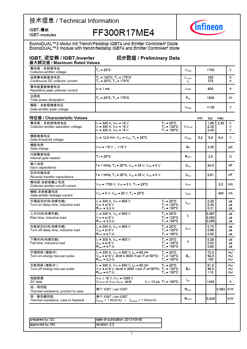
技术信息/TechnicalInformation
6,4 3,0 400
tr
td off
tf
IC = 300 A, VCE = 900 V, LS = 80 nH Tvj = 25°C VGE = ±15 V, di/dt = 3000 A/µs (Tvj=150°C) Tvj = 125°C RGon = 3,3 Ω Tvj = 150°C IC = 300 A, VCE = 900 V, LS = 80 nH Tvj = 25°C VGE = ±15 V, du/dt = 3000 V/µs (Tvj=150°C) Tvj = 125°C RGoff = 4,7 Ω Tvj = 150°C VGE ≤ 15 V, VCC = 1000 V VCEmax = VCES -LsCE ·di/dt 每个IGBT/perIGBT 每个IGBT/perIGBT λPaste=1W/(m·K)/λgrease=1W/(m·K) tP ≤ 10 µs, Tvj = 150°C
特征值/CharacteristicValues
正向电压 Forwardvoltage 反向恢复峰值电流 Peakreverserecoverycurrent 恢复电荷 Recoveredcharge 反向恢复损耗(每脉冲) Reverserecoveryenergy 结-壳热阻 Thermalresistance,junctiontocase 壳-散热器热阻 Thermalresistance,casetoheatsink
FF系列电液伺服阀

FF系列电液伺服阀
型号意义
技术规格
型号
特点
供油压力范围/MPa
1.2/
1.43
FF106A-218
FF106A-234
FF106-100
100
40
>45
>45
FF111
2~21
6、3、15、25、30、50、63、100
15、40
≤4
≤0.5
≤±7.5
≤±10
>30
≤±2
(可调)
≥6
≥60
-30~+100
1.3
FF113双喷嘴挡板力反馈- Nhomakorabea21
150
40
-
-
-
-
≤4
≤1
≤±7.5
≤±10
>30
≤±3
>100
>100
-55~+100
1
FF108
双喷嘴挡板电反馈
2~28
21
60、100
10
≤3
≤0.5
≤±5
≤±5
>30
≤±2
(可调)
≥250
≥250
+20~+65
1.5
FF109P
大功率流量控制三级伺服阀(以FF101作前置级,用差动变压器式位移传感器作第三级滑阀反馈元件)
2~21
EXFO FTB-300 技术规格书说明书
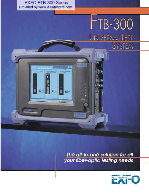
Customized to your needsThe main advantage of the FTB-300 UTS is that the end user can customize itto suit the work environment.Field-interchangeable modules allow the operator to modify the test tool capabilities in a matter of seconds,and as many timesas required in a day’s work.A sound long-term investmentThe open architecture of the FTB-300 UTS provides obvious cost advantages since a single test system is shared between many applications.Without changing the platform,the test set can also be modified with new modules or software upgrades to provide the latest technologies at a fraction of the cost.The FTB-300 UTS really reduces the strain on the test tool budget.A rugged,portable field unitThe FTB-300 UTS is designed to resist the rigors of the worst field conditions as well as stand the test of time.The unit offers shock-proof casing to withstand drops and vibrations.The large,sturdy touch-screen is resistant to shock,water,dust,and common chemicals.The outershell is waterproof with sealed joints,and doorpanels protect connectors,ports,and the floppy disk drive.The FTB-300 UTS also complies to allindustry standards.FTB-7000 Singlemode and Multimode OTDRsThe FTB-300 UTS offers cutting edge OTDR modules to efficiently detect,locate,and analyze fiber splices,connectors,breaks,and other events along a fiber link,as well as a fiber’s loss budget.From high-resolution measurements to high dynamic range requirements,the FTB-300 UTS acts as the perfect mini-OTDR.FTB-5220 Optical Spectrum AnalyzerThe technical specifications of the optical spectrum analyzer (OSA) module meet today’s most advanced dense WDM system requirements.Specifically built for field use,the OSA features a one-button operation for novice users to quickly and easily perform the right tests and obtain precise,comprehensive test results.And more modules to meet your testing needs.Efficient,professional field testingThe FTB-300 UTS puts all the necessary tools in hand for increased productivity.Allapplication software required to operate the different test modules are integrated into a single software: ToolBox 5.This unique user interface gives the operator instant access to all test modules in a true multi- tasking environment,thus increasingtest procedure efficiency.The uniform software presentation for all test modules makes it easy to learn and remember.As these acquired skills apply from one module to another,training costs are significantly reduced and users will not be lost without their manual.All the tools at your fingertips Novices and experts agree that theFTB-300 UTS unique touchscreen provides unsurpassed ease of ers no longer find themselves lost in an endless maze of submenus since all functions areactivated directly on screen with thetouch of a finger.Flexible data storage The FTB-300 UTS standard hard drive provides internal storage capacity fortens of thousands of test results.Data storage options also include an internal floppy disk drive and PCMCIA memorycard.A PCMCIA modem card is also available for transferring test data.Compatible with handheldtest sets The FTB-300 UTS works hand in hand with existing EXFO handheld instruments such as power meters,sources,and talk sets. Some handheld power meters or loss test sets can even download data to the FTB-300 UTS via a serial link or send messages through the fiber under test. The UTS then becomes an integral player on an efficient fiber-optic test team.when special field testing applications areThe use of a hard drive and floppy disk drive enables high-capacity data storage and file backup,facilitates documentation tasks,and provides for easy software upgrades.The PC-basedarchitecture provides the processing power and comprehensive software required for efficienttesting in the field.The UTS hosts up to three field-interchangeable test modules.PCMCIA drive accepts modem cards,memory card,and more.Rubber seals around and between modules keep out humidity and dust.All standard interfaces are included to support a printer,modem,mouse,external keyboard,external monitor,etc.Shock-absorbing bumpers offer a high degree of protection in the field.The FTB-300 UTS meets all Bellcore drop-test requirements.Sealed componentsensure hassle-free testing in any environment.All functions areactivated quickly and easily by touching the non-capacitive screen.1NOTES1.When ordering,specify preferred language for default software interface.If documentation in the specified language is not available,English will be used.2.For North America only.CORPORATE HEADQUARTERS: 400 Godin Avenue,Vanier, QC, G1M 2K2 Canada Tel.: (418) 683-0211 Fax: (418) 683-2170EXFO AMERICA: 4275 Kellway Circle, Suite 122, Addison, TX, 75001 USA Tel.: 1 800 663-3936 Fax: (972) 836-0164EXFO EUROPE:Centre d’Affaires-Les Metz,100,rue Albert Calmette,78353 Jouy-en-Josas,France Tel.: +33 1 34 63 00 20 Fax: +33 1 34 65 90 931 800 663-3936 *************I S 901Q U AL I T YO 0E X F OCER T I F I ED1NOTES1.All specifications are for temperature of 23°C/73°F .2.Standard recharge time is 5 hours.Recharge temperature: 0°to 35°C/32°to 95°F (for full battery recharge).3.Not including internal 3.5”floppy disk drive,batteries,or PCMCIA card.Battery maximum storage temperature: 40°C/104°F .4.Platform with batteries,no modules included.SPFTB-300.5an。
贝士德FC300说明书(完整资料).doc

此文档下载后即可编辑目录第一章、概述1.1前言 (1)1.2检查与安全注意事项 (1)1.3规格型号表 (4)1.4制动单元与制动电阻 (5)第二章、安装与接线2.1机箱结构和尺寸 (6)2.2安装要求 (8)2.3接线要求 (8)2.4接线说明 (9)第三章、运行操作3.1操作面板 (13)3.2操作键盘说明 (13)3.3显示内容说明 (14)3.4参数修改方法 (14)3.5试运行 (15)第四章、功能参数一览表 (16)附表1 多段速一、二、三通断状态与频率的对应关系表 (36)附表1 加减速时间选择一、二通断状态与加减速时间的对应关系表 (36)第五章、故障处理方法5.1维护检查注意事项 (37)5.2定期检查专案 (37)5.3故障信息及故障排除 (37)5.4故障及分析 (39)5.5常见异常现象及对策 (41)第六章、品质承诺 (43)第一章概述1.1前言FC300系列变频器是针对各种专用场合而精心设计的一款多功能高性能产品。
调试参数简单实用,只须一键设置便可改为您需要的专用机型,再加上参数拷贝功能,使您在使用本变频器时变得异常的简单。
使用之前请务必熟读此说明书,便于您更好的使用此变频器,阅读后请妥善保管,对以后的维护,保护及其他使用场合有很好的帮助。
如在使用过程中存在着无法解决的问题,请您随时与本公司联系。
为了您的安全,请务必由合格的专业电机工程人员安装调试及修改参数。
本手册中有请您配合,使变频器使用更加安全。
1.2检查与安全注意事项FC300系列变频器在出厂之前已经过测试和品质检验,在购买之后。
拆箱之前请检查产品包装是否因运输不慎而造成损失,产品的规格和型号,是否与定购机种相符,如有问题请与本公司联系。
1.2.1 拆箱后检查1 内含本机使用说明书一本,保修卡及合格证一张。
2检测变频器侧面的铭牌,以确定在您手上的产品是您说定购的产品。
变频器铭牌说明变频器型号说明:1.2.2安全注意事项成严重的后果,请遵循两个等级的注意事项,它们对我们的个人安全都很重要1.2.3搬运和放置注意事项送电前●所选用电源电压必须与变频器输入电压规格相同。
FF300R12KS4_icpdf
,-. ( 0 ! $ ;T$ U $ ; U V W V W $ ; U U W W ,-. (
)3 J
9 9 L L L L L L L L [ [ [ [
,3 %&' ( )*+ ,
4- ( 93 ,-. ( 2 ,B. ( X0) , B65 ( 3 N 4- ( 93 ,-. ( 2 ,B. ( X0) , B65 ( 3 N
FF300R12KS4
%&' ( )*+ %- ( 2 *+3 %&' ( 0) *+ %- ( )*+3 %&' ( 0) *+
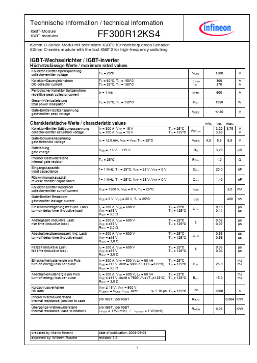
IGBT-Wechselrichter / IGBT-inverter
! ! 1+ : ! ? ? $ " , @ # ; ! $ $ $ ! # ; " 1 $ # $ $
U U , W
W
20 18 16 14 12
" u [v " u [v
"SPh3 %&' ( 0 )*+
20 18 16 14 12 10 8 6 4 2 0 100
F @
"SPh3 %&' ( 0 )*+
10 8 6 4 2 0 200 300 400 500 600
0
4f u9v 1
0
2
4
6
8
10 12 14 16 18 20
IGBT-Module IGBT-modules
FF300R12KS4
#3 ( ) O;3 ( 0
Modul / module
4 :R $ $ R ! $ V , $ ! ; ! $ b $ $ ! F 3 F $ @ + 3 OT E % V $ $ 9 ; $ $ 9 ; $ s ? @ @ $ s ! 9 R # @ 2 ` $ $ # @ 2 2 $ 2 $ $ $ $ $ $R $ $ $R $ $ 9 9 ! ! t t ? ; F _ $ # # @ $ 3 %- ( )*+3 # D @ --pq..p 38 N @ ! c<HGAP ( 0 @ $ E $ 4 ! ! ! ! R !T ! D R !T ! D D D ! ! +%4 D DU ^ W D cdSPHGP ( 0 DU ^ W $ ,i/jk 3) + 9 lmn 3 3 3 003 oJ E AI-e VG-. 3 0 D O !,
FF300R12KE4中文资料
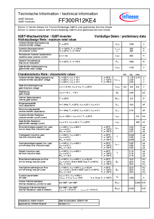
nical information
IGBT-Module IGBT-modules 62mm C-Serien Modul mit Trench/Feldstopp IGBT4 und optimierter EmCon Diode 62mm C-series module with trench/fieldstop IGBT4 and optimized EmCon Diode
1
wBJa- 3@`%
90
" u [v
0,1
75 60 45 30
0,01
7
8 1 29 1 ) 1 1 9 2
15 0 0 2
R !AG
Mu E v Mu v
1 1
))
1 7 9 1
4
:
6
8
C uNv
10
12
14
16
18
0
0,001 0,001
!
0,01
0
0,1
u v U U
1
W W
10
#
$ 3- ( U,-.W ,C. ( X ) ,1 C5ZZ (
3@`% 3@`%
U `#m:W U `#m:W
A 3f ( U,fW
N1 %&' ( ) *+
700 600 500 400 300 200 100 0 0 200 400 600 800 1000 1200 1400
3-1 3-1 +
600 500 400
3f u:v
%&' ( )*+ %&' ( )*+ %&' ( ) *+
300系列交流伺服驱动器随机手册
300系列交流伺服驱动器随机手册感谢您购买本产品。
本手册介绍了300系列交流伺服驱动器的外形尺寸、安装及配线,更详细内容请查阅300系列交流伺服驱动器使用手册。
使用前,请阅读300系列交流伺服驱动器使用手册,在熟知设备的知识、安全信息及注意事项等所有相关内容之后再使用本产品。
手册编码:32020085,版本:V1.1,归档:2016年7月22日安全上的注意事项 (在使用前请务必阅读)本手册中,安全注意事项分为“危险”、“注意”两个等级,如下表所示。
注:这两个等级记载的都是非常重要的内容,“注意”这个级别中所记载的事项,根据状况的不同也可能严重的后果,因此请务必遵守。
1 伺服驱动器与电机1.1 伺服驱动器列表最大电流 通用型智能型运动控制型 10A GSD300-S10□○ ISD300-S10□○ MSD300-S10□○ 15A GSD300-S15□○ ISD300-S15□○ MSD300-S15□○ 20A GSD300-S20□○ ISD300-S20□○ MSD300-S20□○ 25A GSD300-S25□○ ISD300-S25□○ MSD300-S25□○ 35A GSD300-S35□○ ISD300-S35□○ MSD300-S35□○ 50A GSD300-S50□○ ISD300-S50□○ MSD300-S50□○ 100AGSD300-SA0□○ISD300-SA0□○MSD300-SA0□○注:伺服驱动器中的□是编码器类型标识,○是非标或特殊型号标识(标准型号为缺省),详见选型手册。
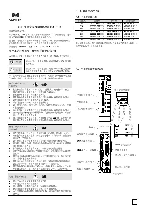
1.2 伺服驱动器各部分名称控制电源端子安装孔(2处)DBUS IBUS伺服驱动器的面板分为显示部分(5位7段LED)和操作部分(4个按钮),可进行伺服驱动器的状态显示、报警和参数设定。
通过“SHIFT”按钮可以切换显示内容,切换画面如下所示。
1.3 伺服驱动器尺寸与重量最大电流A(mm) B(mm) C(mm) D(mm) E(mm) 重量(kg) 10-20A 173 45 170 163 27.5 1.5 25A-50A 173 65 180 163 47.5 2 100A 212 82 202 202 64.5 2.9注:图示仅用于说明安装尺寸,实际外观,请参照实际购买的产品。
PWM-300 产品说明书
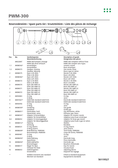
PWM-300Reservedelsliste / Spare parts list / Ersatzteilliste / Liste des pièces de rechangePos. No. Varebetegnelse Description of goodsWarenbezeichnung Désignation des pièces84022847 PWM 300 komplet u/slange PWM 300 complete without hosePWM 300 ohne Schlauch PWM 300 complet sans tuyau1.1 84086542* Keramikdyse Ceramic nozzleKeramikdüse Buse céramique1.2 84084373 Gasdyse, messing Gas nozzle, brassGasdüse, Messing Buse à gaz en laiton2 84086575 Dyse 2,36 200A Nozzle 2.36 200ADüse 2,36 200A Buse 2,36 200A2 84086582* Dyse 2,87 250A Nozzle 2.87 250ADüse 2,87 250A Buse 2,87 250A2 84086572 Dyse 3,18 300A Nozzle 3.18 300ADüse 3,18 300A Buse 3,18 300A2 84084370 Dyse 200 AMP-LG Nozzle 200 AMP-LGDüse 200 AMP-LG Buse 200 AMP-LG2 84084371 Dyse 250 AMP-LG Nozzle 250 AMP-LGDüse 250 AMP-LG Buse 250 AMP-LG2 84084372 Dyse 300 AMP-LG Nozzle 300 AMP-LGDüse 300 AMP-LG Buse 300 AMP-LG3 84092863 O-ring O-ringO-Ring Joint4 84091827* Elektrode standard 4,8x91mm Electrode standard 4.8x91mmElektrode standard 4,8x91mm Elektrode standard 4,8x91mm5 84092956 O-ring O-ringO-Ring Joint6 84086509* Gasføring Gas guideGasführer Guide gaz7 84086651* Gasfordeler, hvid Gas distributor, whiteGasverteiler, weiss Diffuseur gaz, blanc8.1 84086541* Adapter til keramikdyse Adaptor for ceramic nozzleAdapter für Keramikdüse Adapteur pour buse ceramique8.2 84086652 Adapter til messinggasdyse Adaptor for brass gas nozzleAdapter für Messinggasdüse Adapteur pour buse à gaz en laiton9 84086512* Pakning WasherDichtung Rondelle10 84080531 O-ring 25x015 O-ring 25x015O-Ring 25x015 Joint 25x01511 84086649* Brænderkrop, PWM300 Torch body, PWM300Brennerkörper, PWM300 Corps de torche, PWM30012 84083487 O-ring O-ringO-Ring Joint13 84086650* Elektrodetang Electrode tongSpannhülse Pince électrodes14 84086654* Elektrodehætte Electrode capBrennerkappe Bouchon d’électrode15 84086517 Nøgle for dyse Key for nozzleSchlüssel für Düse Cle pour buse16 84086653 Indstillingslære Adjusting deviceEinstelllehre Dispositif de reglage*Sliddele monteret som standard Fitted as standard equipmentMontiert als Standard Équipements standards50119527。
英飞凌IGBT (ff300r)说明书

300 200 100 0 0,0
% %
300 200 100
0,5
1,0
#
1,5
-./ u-v
2,0
2,5
3,0
U W
3,5
W
4,0
0
0,0 0,5 1,0 1,5 2,0 2,5 3,0 3,5 4,0 4,5 5,0
-./ u-v U U W W -
b
# 4?`& 4?`&
U
4. ) U-B/W -./ ) -
-
600 550 500 450 400 300 250 200 150 100 50 0 0 5
Q #@F 4. ) U-./W -B/ ) X!* -3 wAIa. u"D v $ u [v
$653 &'( ) ! *+, $6ZZ3 &'( ) ! *+,
1
wAIa. 4?`&
0,1
350
0,01
K, M P P
-B/ ) !* &'( ) *+,
) ! N ;3 &'( ) *+,3 -./ ) * -3 -B/ ) ) ! N ;3 &'( ) *+,3 -./ ) * -3 -B/ ) -./ ) ! -3 -B/ ) -3 -B/ ) -3 &'( ) *+,
Q #@ # " ? % $ # $
U U W W
1 @ % $ROh ) U4fW B65 ) 3 M3 -./ ) S
U U -
1 @ % $ROh ) U BW 4f ) 8 93 -./ ) SBiblioteka 100 90 80 70 60
74ls00中文资料_数据手册_参数

74LS00包类型包画画引脚包数量生态计划 (2)铅/球完成 MSL峰值温度 (3) SNJ5400W活性 CFP W ^ 14 1没有打电话给TI等级-NCNC-NC SNJ5400WA已过时 CFP WA 14没有打电话给TI等级-NC-NC-NC SNJ54LS00FK活性 LCCC FK 20 1没有打电话给TI等级SNJ54LS00J 活性 CDIP ? 14 1没有打电话给TI等级SNJ54LS00W活性 CFP W ^ 14 1没有打电话给TI等级SNJ54S00FK活性 LCCC FK 20 1没有打电话给TI 等级SNJ54S00J活性 CDIP ? 14 1没有打电话给TI等级74LS00活性 CFP W ^ 14 1没有打电话给TI等级(1) 营销状况值定义如下: ACTIVE:74LS00推荐用于新设计的产品设备. LIFEBUY:TI已经宣布该设备将停产,终身购买期限已经生效. NRND:不建议用于新设 计.器件正在生产中以支持现有客户,但TI不建议使用此74LS00部分一个新的设计.预览:设备已被宣布,但尚未投入生产.样品或提供或 不提供.停产:TI已停止生产该设备. (2) 生态计划 - 目前可能无法使用 - 74LS00请查阅取新的可用性信息和附加信息产品内容细节. 无:尚未提供铅(无铅).无铅(ROHS):TI的术语“无铅”或“无铅”是指符合当前ROHS要求的半导体产品对于所有6种物 质,74LS00包括在均质材料中铅含量不超过0.1%的要求.在哪里设计焊接在高温下,TI无铅产品适用于特定的无铅工艺.绿色(ROHS和 无SB / BR):TI将“绿色”定义为“无铅”,另外使用不含卤素的包装材料,包括总产品重量的0.1%以上的溴(BR)或锑(SB). (3) MSL,PEAK TEMP. - 根据JEDEC行业标准分类
Flux 424 80 027 产品说明书

Ersatzteilliste 424 80 027 •01/12Fasspumpe aus PP oder PVDFSpare parts listBarrel Pump in PP or PVDFListe de pièces de rechangePompe Vide-fûts en PP ou PVDFFE 0112/1F 424 PP - 50/38F 424 PP - 50/43 ZF 424 PVDF - 50/38Ta l w e g 12·D -75433 Ma u l b r o n n T el.07043/101-0 · Fax 07043/101-444Fax International ++49 70 43 / 1 01 -555*******************·www.flux-pumpen.deParts included in Maintenance Kits are circled on the exploded view andin BOLD on the parts list.Änderungen vorbehalten.Stück/Pos.Gerät Bestell-Nr. / Part No. / RéférenceNr.Qty./BestellbezeichnungDescriptionRep.Unit Qté./ F 424 PP F 424 PP F 424 PVDF Unité-50/38-50/43Z -50/381Innenrohr kpl., Pos. 1-10 und 16 Inner tube cpl., Pos. 1-10 and 16 Eintauchtiefe 700mm 424 41 221424 41 247424 61 221 Immersion length 700mm Eintauchtiefe 1000mm 424 41 224424 41 250424 61 224 Immersion length 1000mm Eintauchtiefe 1200mm 424 41 226424 41 252242 61 226 Immersion length 1200mm Eintauchtiefe 1500mm424 41 229-424 61 229Immersion length 1500mm1 Kupplungskäfig kpl., Pos 1-4424 41 238424 41 238424 41 23811 Kupplungsstern 410 14 028410 14 028410 14 02821 Kupplungskäfig 424 41 232424 41 232424 41 23232 Rillenkugellager 922 40 005922 40 005922 40 00541 Distanzhülse 908 83 019908 83 019908 83 019 Coupling cage cpl., Pos. 1-4 Coupling star Coupling cageGrooved ball bearing Distance sleeve51 WelleShaftEintauchtiefe 700mm 424 41 507424 41 507424 41 507 Immersion length 700mm Eintauchtiefe 1000mm 424 41 510424 41 510424 41 510 Immersion length 1000mm Eintauchtiefe 1200mm 424 41 512424 41 512424 41 512 Immersion length 1200mm Eintauchtiefe 1500mm424 41 515-424 41 515Immersion length 1500mm62925 11 001925 11 001925 11 00171424 41 721424 41 721424 61 721 Shaft seal (FKM)Inner tube with Pos. 6, 8 and 10Immersion length 700mm 424 41 724424 41 724424 61 724 Immersion length 1000mm 424 41 726424 41 726424 61 726 Immersion length 1200mm Wellendichtring (FKM)Innenrohr mit Pos. 6, 8 und 10 Eintauchtiefe 700mm Eintauchtiefe 1000mm Eintauchtiefe 1200mm Eintauchtiefe 1500mm 424 41 729-424 61 729 Immersion length 1500mm 81FührungslagerGuide bearingEintauchtiefe 700mm 424 41 239424 41 239424 41 239 Immersion length 700mm Eintauchtiefe 1000mm 424 41 236424 41 236424 41 236 Immersion length 1000mm Eintauchtiefe 1200mm 424 41 237424 41 237424 41 237 Immersion length 1200mm Eintauchtiefe 1500mm424 41 240-424 41 240Immersion length 1500mm91925 65 003925 65 003925 65 003101 O-Ring Ø 32,2 x 3 (FKM ) Zentrierstern424 61 037424 61 037424 61 037 O-Ring Ø 32,2 x 3 (FKM) Centering star 1Außenrohr kpl. 11-15 und 17 Outer tube cpl. Pos. 11-15 and 17 Eintauchtiefe 700 mm 424 90 207424 90 307424 90 607 Immersion length 700 mm Eintauchtiefe 1000 mm 424 90 210424 90 310424 90 610 Immersion length 1000 mm Eintauchtiefe 1200 mm 424 90 212424 90 312424 90 612 Immersion length 1200 mm Eintauchtiefe 1500 mm424 90 215424 90 315424 90 615Immersion length 1500 mm111918 80 002918 80 002918 80 002121907 90 003907 90 003907 90 003131424 41 036424 41 036424 61 036141424 41 127424 41 127424 61 127424 41 130424 41 130424 61 130424 41 132424 41 132424 61 132 Sicherungsring Überwurfmutter T-StückRohr für Außenrohr Eintauchtiefe 700mm Eintauchtiefe 1000mm Eintauchtiefe 1200mm Eintauchtiefe 1500mm 424 41 135-424 61 135 Circlip Union nut T-pieceTube for outer tubeImmersion length 700mm Immersion length 1000mm Immersion length 1200mm Immersion length 1500mm151 Lagergehäuse 424 41 038424 41 038424 61 038 Bearing housing 161 Rotor 420 24 296430 41 301420 24 296 Impellor 171 Fußstück424 41 039430 41 200424 61 039 Foot pieceLebensmittel-Schmierfett / kg 952 00 012952 00 012952 00 012 Food grade grease / kg(für Wellendichtringe) (for shaft seals)Zubehör:Accessories:1959 04 053959 04 053959 04 101181925 64 002925 64 002925 64 003191959 05 067959 05 067959 05 084201 Schlauchanschluss DN 19, Pos. 18-20 FlachdichtungSchlauchstecker DN 19Knebelüberwurfmutter G 1 1/4907 90 024907 90 024907 90 026 Hose connection DN 19, Pos. 18-20 Flat sealHose connector DN 19 Union nut G 1 1/4wahlweise:optional:1 Schlauchanschluss DN 25, Pos. 18-20959 04 052959 04 052959 04 102 Hose connection DN 25, Pos. 18-20181 Flachdichtung925 64 002925 64 002925 64 003 Flat seal191 Schlauchstecker DN 25959 05 066959 05 066959 05 085 Hose connector DN 25201 Knebelüberwurfmutter G 1 1/4907 90 024907 90 024907 90 026Union nut G 1 1/4211FLUX-Clip001 10 424001 10 424001 10 424 FLUX-ClipRights reserved to make alterations。
PH300S280-24中文资料

For Additional Information, please visit /products/ph-series-sf.htm
3055 Del Sol Blvd • San Diego, CA 92154 • 1-800-LAMBDA-4
Revision A3: Mar 2004
Pinout
Pin Description -Vin +Vin +S -S +V -V IOG TRIM CNT CS Function Negative Input Terminal Positive Input Terminal Positive Remote sense Negative Remote sense Positive Output Terminal Negative Output Terminal Inverter Good Signal Output adjustment trim pin On/Off Control Terminal Current Monitor Signal
Note: See Installation Manual for full details, test methods of parameters and application notes (1) PH300S48 models: Input to output 1.5kVAC, input to baseplate 1.5kVAC
元器件交易网
PH-S Series
Siers
High Density Wide Range Input Output adjustment Capability Remote On/Off Fixed Switching Frequency International Safety Approvals
ANSI Class 300 气体控制阀门说明书
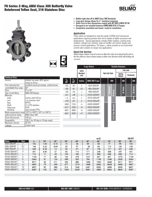
800-543-9038 866-805-7089 203-791-8396 •Bubble tight shut-off to ANSI Class 300 Standards • Long stem design allows for 2” insulation minimum• Valve Face-to-face dimensions comply with API 609 & MSS-SP-68•Designed to be installed between ASME/ANSI B16.5 Flanges •Completely assembled and tested, ready for installationApplicationThese valves are designed to meet the needs of HVAC and Commercial applications requiring positive shut-off for liquids at higher pressures and temperatures. Typical applications include chiller isolation, cooling tower isolation, change-over systems, large air handler coil control, bypass and process control applications. The large C v values provide for an economical control valve solution for larger fl ow applications.Dead End ServiceUtilizes larger retainer ring set screws to allow the valve to be placed at the end of the line without a down stream fl ange in either fl ow direction while still holding full pressure.MOD ON/OFF ValveSize C v 10°20°30°40°50°60°70°80°90°F650-300SHP 2”F665-300SHP 2½”F680-300SHP 3”F6100-300SHP 4”F6125-300SHP 5”F6150-300SHP 6”F6200-300SHP 8”F6250-300SHP 10”F6300-300SHP 12”F6350-300SHP 14”F6400-300SHP 16”F6 Series 2-Way, ANSI Class 300 Butterfl y Valve Reinforced Tefl on Seat, 316 Stainless DiscTechnical Data Servicechilled, hot water, 60% glycol,steam to 50 psi Flow characteristic modifi ed equal percentage, unidirectional Controllable fl ow range 82°Sizes2" to 24"Type of end fi tting ANSI 300 fl anges Materials Body Disc Seat ShaftGland seal Bushingscarbon steel full lug 316 stainless steel RPTFE17-4 PH stainless PTFEglass backed PTFEMedia temperature range -20°F to 400°F [-30°C to 204°C]Body pressure rating ANSI Class 300Close-off pressure 740 psiRangeability100:1 (for 30 deg to 70 deg range)Maximum velocity 32 FPS Leakagebubble tight2-way ValvesSuitable ActuatorsValve Nominal SizeNon Fail-SafeFail-SafeSpring ReturnElectronicC v90°C v 60°Inches ANSI 300 2-way 300300300102562F650-300SHP G M S e r i e sP R S e r i e sA F S e r i e sG K S e r i e s146802½F665-300SHP2281253F680-300SHP 4512484F6100-300SHP 7143925F6125-300SHP P K R11036076F6150-300SHP 206411358F6200-300SHPS Y (2 Y e a r W a r r a n t y )3517193410F6250-300SHP 4837266012F6300-300SHP 6857359214*F6350-300SHP102 1.50 6.10142639567799102146 2.208.8020375580110142146228 3.4014325787125171221228451 6.8027631141712483384374517141143100180271393536693714110317661542784196078271070110320643112428952078411351548200220643517532114928861336193426383411351748377329067712191838266036284692483768579039291416462481359248986530685792871325311230222933614865663488459287203-791-8396 F6 Series 2-Way, ANSI Class 300 Butterfl y ValveReinforced Tefl on Seat, 316 Stainless DiscDimension “A” does not include fl ange gaskets. (2 required per valve)Application Notes 1. V alves are rated at 725 psi differential pressure in the closed position @ 100°F media temperature.2. Valves are furnished with lugs tapped for use between ANSI Class 250/300 fl anges conforming to ANSI B16.5 Standards.3. 2-way assemblies are furnished assembled, calibrated and tested, ready for installation.4. Dimension “D” allows for actuator(s) removal without the need to remove the valve from the pipe.5. Weather shields are available, dimensional data furnished upon request.6. Dual actuated valves have actuators mounted on a single common shaft.7. Flange gaskets (2 required, not provided with valve) MUST be used between valve and ANSI fl ange.8. F lange bolts are not included with the valve. These are furnished by others.Maximum Dimensions (Inches)F650-300SHP 2”102 1.759.009.0019.50 5.0085/8-11 UNC 2*AF150Spring Return F665-300SHP 2½”146 1.889.009.0020.00 5.8883/4-10 UNC 150F680-300SHP 3”228 1.929.009.0020.50 6.6383/4-10 UNC 150F6100-300SHP 4”451 2.139.009.0021.007.8883/4-10 UNC 150F650-300SHP 2”1.759.009.0019.50 5.0085/8-11 UNC GK150Electronic Fail-Safe F665-300SHP 2½”1.889.009.0020.00 5.8883/4-10 UNC 150F680-300SHP 3”1.929.009.0020.50 6.6383/4-10 UNC 150F6100-300SHP 4”2.139.009.0021.007.8883/4-10 UNC 150F650-300SHP 2” 1.759.009.0019.50 5.0085/8-11 UNC 2*GK400F665-300SHP 2½” 1.889.009.0020.00 5.8883/4-10 UNC 400F680-300SHP 3” 1.929.009.0020.50 6.6383/4-10 UNC 400F650-300SHP 2”1.759.009.0019.50 5.0085/8-11 UNC GM285Non-Spring Return Electronic Fail-Safe (K)F665-300SHP 2½”1.889.009.0020.00 5.8883/4-10 UNC 285F680-300SHP 3”1.929.009.0020.50 6.6383/4-10 UNC 285F6100-300SHP 4”2.139.009.0021.007.8883/4-10 UNC 150F650-300SHP 2” 1.758.008.0022.25 4.7585/8-11 UNC PR/PKR 600F665-300SHP 2½” 1.888.008.0022.75 5.5083/4-10 UNC 600F680-300SHP 3” 1.928.008.0023.00 6.0083/4-10 UNC 600F6100-300SHP 4” 2.138.008.0023.757.5083/4-10 UNC 600F6125-300SHP 5”714 2.258.008.0024.259.2583/4-10 UNC PR/PK 400F6150-300SHP 6”1103 2.298.008.0024.7510.63123/4-10 UNC PR/PK 285F6200-300SHP 8”2064 2.8812.0012.0032.0013.00127/8-9 UNC SY4…600F6250-300SHP 10”3517 3.2512.0012.0033.0015.25161-8 UNC SY5…400SY7…600F6300-300SHP 12”4837 3.6212.0012.0035.0017.7516 1 1/8-8 UNC SY5…285SY7…600F6350-300SHP14”68574.6214.0014.0036.0020.25201 1/8-8 UNCSY7…400SY8…600ACBD102146228451102146228102146228451102146228451PRXUP-MFT-T Modulating, Non Fail-Safe, 24...240 V, NEMA4X with BACnetTechnical dataElectrical data Nominal voltage AC 24...240 V / DC 24...125 VNominal voltage frequency50/60 HzPower consumption in operation20 WPower consumption in rest position 6 WTransformer sizing20 VA @ AC/DC 24 V (class 2 power source), 23VA @ AC/DC 120 V, 52 VA @ AC 230 VAuxiliary switch 2 x SPDT, 3 A resistive (0.5 A inductive) @ AC250 V, 1 x 10° / 1 x 0...90° (default setting 85°)Switching capacity auxiliary switch 3 A resistive (0.5 A inductive) @ AC 250 VElectrical Connection Terminal blocks, (PE) Ground-ScrewOverload Protection electronic thoughout 0...90° rotationFunctional data Communicative control BACnet MS/TPModbus RTUMP-BusOperating range Y 2...10 VOperating range Y note 4...20 mAInput Impedance100 kΩ for 2...10 V (0.1 mA), 500 Ω for 4 (20)mA, 1500 Ω for On/OffOperating range Y variable Start point 0.5...30 VEnd point 2.5...32 VOptions positioning signal variable (VDC, on/off, floating point)Position feedback U 2...10 VPosition feedback U note Max. 0.5 mAPosition feedback U variable VDC variableDirection of motion motor reversible with appManual override7 mm hex crank, suppliedAngle of rotation90°Running Time (Motor)default 35 s, variable 30...120 sRunning time motor variable30...120 sNoise level, motor68 dB(A)Position indication integral pointerPassive sensor inputs2x (Pt1000, Ni1000, NTC10k2)Safety data Degree of protection IEC/EN IP66/67Degree of protection NEMA/UL NEMA 4XEnclosure UL Enclosure Type 4XAgency Listing cULus acc. to UL60730-1A/-2-14, CAN/CSAE60730-1:02, CE acc. to 2014/30/EU and2014/35/EU-22...122°F [-30...50°C]PRXUP-MFT-TApplicationOperationSafety dataStorage temperature -40...176°F [-40...80°C]Ambient humidity Max. 100% RH Servicingmaintenance-free Weight Weight13 lb [5.9 kg]MaterialsHousing materialDie cast aluminium and plastic casingProduct featuresPR Series valve actuators are designed with an integrated linkage and visual position indicators. For outdoor applications, the installed valve must be mounted with the actuator at or above horizontal. For indoor applications the actuator can be in any location including directly under the valve.The PR series actuator provides 90° of rotation and a visual indicator shows the position of the valve. The PR Series actuator uses a low power consumption brushless DC motor and is electronically protected against overload. A universal power supply is furnished to connect supply voltage in the range of AC 24...240 V and DC 24...125 V. Included is a smart heater with thermostat to eliminate condensation. Two auxiliary switches are provided; one set at 10° open and the other is field adjustable. Running time is field adjustable from 30...120 seconds by using the Near Field Communication (NFC) app and a smart phone.†Use 60°C/75°C copper wire size range 12...28 AWG, stranded or solid. Use flexible metal conduit. Push the listed conduit fitting device over the actuator’s cable to butt against the enclosure. Screw in conduit connector. Jacket the actuators input wiring with listed flexible conduit. Properly terminate the conduit in a suitable junction box. Rated impulse Voltage 4000 V. Type of action 1. Control pollution degree 3.AccessoriesGatewaysDescriptionType Gateway MP to BACnet MS/TP UK24BAC Gateway MP to LonWorks UK24LON Gateway MP to Modbus RTUUK24MOD Electrical accessoriesDescriptionType Service Tool, with ZIP-USB function, for programmable andcommunicative Belimo actuators, VAV controller and HVAC performance devicesZTH USMechanical accessoriesDescriptionType Hand crank for PR, PKR, PM ZG-HND PR Service toolsDescriptionTypeConnection cable 10 ft [3 m], A: RJ11 6/4 ZTH EU, B: 3-pin Weidmüller and supply connectionZK4-GEN Service Tool, with ZIP-USB function, for programmable and communicative Belimo actuators, VAV controller and HVAC performance devicesZTH USElectrical installationMeets cULus requirements without the need of an electrical ground connection.Universal Power Supply (UP) models can be supplied with 24 V up to 240 V.Disconnect power.Provide overload protection and disconnect as required.Two built-in auxiliary switches (2x SPDT), for end position indication, interlock control, fanstartup, etc.Only connect common to negative (-) leg of control circuits.Actuators may be controlled in parallel. Current draw and input impedance must be observed.PRXUP-MFT-TDuring installation, testing, servicing and troubleshooting of this product, it may be necessaryto work with live electrical components. Have a qualified licensed electrician or other individualwho has been properly trained in handling live electrical components perform these tasks.Failure to follow all electrical safety precautions when exposed to live electrical componentscould result in death or serious injury.Wiring diagramsOn/OffOn/OffBACnetModulatingPRXUP-MFT-T Floating PointTemperature Sensors Auxiliary SwitchesDimensionsDimensional drawings。
AOB508经济型数字指示控制仪说明书
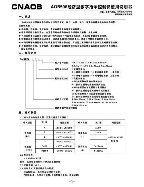
AOB508经济型数字指示控制仪使用说明书安装、使用产品前,请阅读使用说明书该说明书请保留备用AOB508经济型数字指示控制仪适用于温度、压力、流量、液位、湿度等多种参数的测控和报警。
主要特点如下:●热电偶、热电阻、直流电压、直流电流等多种信号可编程输入。
●输入采用数字校正系统,内置常用热电偶和热电阻非线性校正表格,测量准确。
●可自由切换位式控制(ON/OFF)和PID 控制并可设置正反作用,具备PID 参数自整定功能。
●控制输出支持继电器触点开关、固态继电器(SSR)驱动电压、单相可控硅过零触发信号等。
●一路可编程的报警输出可实现上限或下限报警功能。
可设置上电保持以避免仪表上电时报警误动作。
●具有完善的自检、保护功能。
发生错误时能根据错误性质自动修正错误或及时给出提示并关闭输出,确保系统安全。
一、概述二、型号定义1:PID 控制继电器触点开关输出2:二位式控制继电器触点开关输出3:PID 控制固态继电器驱动电压输出4:二位式控制固态继电器驱动电压输出5:PID 控制单相可控硅过零触发信号输出6:二位式控制单相可控硅过零触发信号输出D:72×72mm E:48×96mmG:48×48mm H:160×80mm AOB508-□□□□输入信号类型报警输出方式0:无报警输出1:上限绝对值报警2:上限绝对值报警(上电保持)3:下限绝对值报警4:下限绝对值报警(上电保持)控制输出方式0:无控制输出面板尺寸代码A:96×96mm F:96×48mm S:80×160mm经济型数字指示控制仪0:K 1:S 2:E 3:J 4:Cu505:Pt1006:0-5V 7:1-5V 8:0-20mA 9:4-20mA 三、技术参数3.1输入规格与测量范围(可通过键盘自由切换)输入类型输入类型-1999~+9999自定义规格规格KS E J热电偶(T C)直流电压(U)Cu50测量范围测量范围-50℃~+1350℃-50℃~+1750℃-50℃~+800℃-50℃~+1000℃-50℃~+150℃-200℃~+850℃Pt100热电阻(RTD )0-5V1-5V0-20mA 4-20mA直流电流(I)3.2基本误差:±0.5%FS ±1个字3.3采样周期:<0.3s3.4控制方式(可通过键盘自由切换)位式控制(正、反作用及切换差可设置)PID 控制(正、反作用可设置,PID 参数可手动、自动设置)说明:仪表需要预热15分钟才能准确测量单位:mm四、外形尺寸及开孔尺寸A D E F G H S宽967248964816080高967296484880160宽926845924515276高926892454576152安装开孔尺寸面板尺寸代码高916744904415075深916790444475150宽100100100100100壳体尺寸面板尺寸1001003.5报警方式(可通过键盘自由切换)一路可编程的报警输出可实现上限或下限报警功能(继电器输出)。
5804中文资料

5804中⽂资料Combining low-power CMOS logic with high-current and high-voltage bipolar outputs, the UCN5804B and UCN5804LB BiMOS II translator/drivers provide complete control and drive for a four-phase unipolar stepper-motor with continuous output current ratings to 1.25 A per phase (1.5 A startup) and 35 V.The CMOS logic section provides the sequencing logic, DIRECTION and OUTPUT ENABLE control, and a power-on reset function. Three stepper-motor drive formats, wave-drive (one-phase), two-phase, and half-step are externally selectable. The inputs are compatible with standard CMOS, PMOS, and NMOS circuits. TTL or LSTTL may require the use of appropriate pull-up resistors to ensure a proper input-logic high.The wave-drive format consists of energizing one motor phase at a time in an A-B-C-D (or D-C-B-A) sequence. This excitation mode consumes the least power and assures positional accuracy regardless of any winding inbalance in the motor. Two-phase drive energizes two adjacent phases in each detent position (AB-BC-CD-DA). This sequence mode offers animproved torque-speed product, greater detent torque, and is less susceptible to motor resonance. Half-step excitation alternates between the one-phase and two-phase modes (A-AB-B-BC-C-CD-D-DA), providing an eight-step sequence.The bipolar outputs are capable of sinking up to 1.5 A and withstanding 50 V in the off state (sustaining voltages up to 35 V). Ground-clamp and flyback diodes provide protection against inductive transients. Thermal protection circuitry disables the outputs when the chip temperature is exces-sive.Both devices are rated for operation over the temperature range of -20°C to +85°C. The UCN5804B is supplied in a 16-pin dual in-line plastic batwing package with a copper lead frame and heat-sinkable tabs for improved power dissipation capabilities; the UCN5804LB is supplied in a 16-lead plastic SOIC batwing package with a copper lead frame and heat-sinkable tabs.FEATURESI 1.5 A Maximum Output Current I 35 V Output Sustaining VoltageI Wave-Drive, Two-Phase, and Half-Step Drive Formats I Internal Clamp DiodesI Output Enable and Direction Control I Power-On ResetI Internal Thermal Shutdown CircuitryBiMOS II UNIPOLARSTEPPER-MOTOR TRANSLATOR/DRIVERAlways order by complete part number, e.g., UCN5804B .Data Sheet 26184.12C*5804115 Northeast Cutoff, Box 15036Worcester, Massachusetts 01615-0036 (508) 853-********BiMOS II UNIPOLAR STEPPER-MOTORTRANSLATOR/DRIVERTRUTH TABLEDrive Format Pin 9Pin 10Two-Phase L L One-Phase H L Half-Step L H Step-InhibitHHTYPICAL INPUT CIRCUITDwg. EP-021-4TYPICAL OUTPUT DRIVERDwg. EP-010-5INCopyright ? 1987, 2000 Allegro MicroSystems, Inc.5075100125150510A L L O W A B L E P A C K A G E P O W E R D I S S I P A T I O N I N W A T T STEMPERATURE IN °C43225Dwg. GP-049-2A5804BiMOS II UNIPOLAR STEPPER-MOTOR TRANSLATOR/DRIVER/doc/a3712eddb9f3f90f76c61b7c.htmlELECTRICAL CHARACTERISTICS at T A = 25°C, T J ≤ 150°C, V DD = 4.5 V to 5.5 V (unless otherwise noted). Limits CharacteristicSymbol Test Conditions Min.Typ.Max.Units Output Leakage Current I CEX V OUT = 50 V—1050µA Output Sustaining Voltage V CE(sus)I OUT = 1.25 A, L = 3 mH 35——V Output Saturation VoltageV CE(SAT)I OUT = 700 mA — 1.0 1.2V I OUT = 1 A — 1.1 1.4V I OUT= 1.25 A— 1.2 1.5V Clamp Diode Leakage Current I R V R = 50 V —1050µA Clamp Diode Forward Voltage V F I F = 1.25 A — 1.53.0V Input CurrentI IN(1)V IN = V DD —0.5 5.0µA I IN(0)V IN = 0.8 V —-0.5-5.0µA Input VoltageV IN(1)V DD = 5 V3.5— 5.3V V IN(0)-0.3—0.8V Supply Current I DD 2 Outputs ON—2030mA Turn-Off Delay t ON 50% Step Inputs to 50% Output ——10µs Turn-On Delayt OFF 50% Step Inputs to 50% Output ——10µs Thermal Shutdown TemperatureT J—165—°CTIMING CONDITIONSA. Minimum Data Set Up Time . . . . . . . . . . . . . . . . . . . . . . . . 100 nsB. Minimum Data Hold Time . . . . . . . . . . . . . . . . . . . . . . . . . . 100 nsC. Minimum Step Input Pulse Width . . . . . . . . . . . . . . . . . . . . . 3.0 µsDwg. W-110AONE PHASE HALF STEPOOUTPUT ENABLEOUTPUT C OUTPUT DCLOCK115 Northeast Cutoff, Box 15036Worcester, Massachusetts 01615-0036 (508) 853-50005804BiMOS II UNIPOLAR STEPPER-MOTORTRANSLATOR/DRIVERWAVE-DRIVE SEQUENCEHalf Step = L, One Phase = H Step A B C D POR ON OFF OFF OFF 1ON OFF OFF OFF 2OFF ON OFF OFF 3OFF OFF ON OFF 4OFFOFFOFFONTWO-PHASE DRIVE SEQUENCEHalf Step = L, One Phase = LStep A B C D POR ON OFF OFF ON 1ON OFF OFF ON 2ON ON OFF OFF 3OFF ON ON OFF 4OFFOFFONONHALF-STEP DRIVE SEQUENCEHalf Step = H, One Phase = LStep A B C D POR ON OFF OFF OFF 1ON OFF OFF OFF 2ON ON OFF OFF 3OFF ON OFF OFF 4OFF ON ON OFF 5OFF OFF ON OFF 6OFF OFF ON ON 7OFF OFF OFF ON 8ONOFFOFFONAPPLICATIONS INFORMATIONInternal power-on reset (POR) circuitry resets OUTPUT A (and OUTPUT D in the two-phase drive format) to the on state with initial applica-tion of the logic supply voltage. After reset, the circuit then steps according to the tables.The outputs will advance one sequenceposition on the high-to-low transition of the STEP INPUT pulse. Logic levels on the HALF-STEP and ONE-PHASE inputs will determine the drive format (one-phase, two-phase, or half-step). The DIRECTION pin determines the rotation se-quence of the outputs. Note that the STEP INPUT must be in the low state when changing the state of ONE-PHASE, HALF-STEP, or DIRECTION to prevent erroneous stepping.All outputs are disabled (off) when OUTPUT ENABLE is at a logic high. If the function is not required, OUTPUT ENABLE should be tied low.In that condition, all outputs depend only on the state of the step logic.During normal commutation of a unipolar stepper motor, mutual coupling between the motor windings can force the outputs of the UCN5804B below ground. This condition will cause forward biasing of the collector-to-substrate junction and source current from the output. For many L/R applications, this substrate current is high enough to adversely affect the logic circuitry and cause misstepping. External series diodes (Schottky are recommended for increasedefficiency at low-voltage operation) will prevent substrate current from being sourced through the outputs. Alternatively, external ground clamp diodes will provide a preferred current path from ground when the outputs are pulled below ground.Internal thermal protection circuitry disables all outputs when the junction temperature reaches approximately 165°C. The outputs are enabled again when the junction cools down to approxi-mately 145°C.5804BiMOS II UNIPOLAR STEPPER-MOTOR TRANSLATOR/DRIVER/doc/a3712eddb9f3f90f76c61b7c.htmlTYPICAL APPLICATION L/R Stepper-Motor DriveThe products described here are manufactured under one or more U.S. patents or U.S. patents pending.Allegro MicroSystems, Inc. reserves the right to make, from time to time, such departures from the detail specifications as may berequired to permit improvements in the performance, reliability, or manufacturability of its products. Before placing an order, the user is cautioned to verify that the information being relied upon is current.Allegro products are not authorized for use as critical components in life-support devices or systems without express written approval.The information included herein is believed to be accurate and reliable. However, Allegro MicroSystems, Inc. assumes no responsi-bility for its use; nor for any infringement of patents or other rights of third parties which may result from its use.115 Northeast Cutoff, Box 15036Worcester, Massachusetts 01615-0036 (508) 853-50005804BiMOS II UNIPOLAR STEPPER-MOTORTRANSLATOR/DRIVERUCN5804BDimensions in Inches (controlling dimensions)Dimensions in Millimeters(for reference only)NOTES:1.Exact body and lead configuration at vendor’s option within limits shown.2.Lead spacing tolerance is non-cumulative.3.Lead thickness is measured at seating plane or below.4.Webbed lead frame. Leads 4, 5, 12, and 13 are internally one piece.5.Supplied in standard sticks/tubes of 25 devices.Dwg. MA-001-17A in18Dwg. MA-001-17A mm185804 BiMOS II UNIPOLAR STEPPER-MOTOR TRANSLATOR/DRIVER/doc/a3712eddb9f3f90f76c61b7c.htmlUCN5804LB(add “TR” to part number for tape and reel) Dimensions in Inches(for reference only)Dimensions in Millimeters(controlling dimensions)NOTES:1.Exact body and lead configuration at vendor’s option within limits shown.2.Lead spacing tolerance is non-cumulative.3.Lead thickness is measured at seating plane or below.4.Webbed lead frame. Leads 4, 5, 12, and 13 are internally one piece.5.Supplied in standard sticks/tubes of 47 devices or add “TR” to part number for tape and reel.115 Northeast Cutoff, Box 15036Worcester, Massachusetts 01615-0036 (508) 853-50005804BiMOS II UNIPOLAR STEPPER-MOTORTRANSLATOR/DRIVERMOTOR DRIVERSFunctionOutput Ratings*Part Number ?INTEGRATED CIRCUITS FOR BRUSHLESS DC MOTORS3-Phase Power MOSFET Controller —28 V 39333-Phase Power MOSFET Controller —50 V 39323-Phase Power MOSFET Controller —50 V 76002-Phase Hall-Effect Sensor/Driver 400 mA 26 V 3626Bidirectional 3-Phase Back-EMFController/Driver ±600 mA 14 V 89062-Phase Hall-Effect Sensor/Driver 900 mA 14 V 36253-Phase Back-EMFController/Driver ±900 mA 14 V 8902–A 3-Phase Controller/Drivers ±2.0 A 45 V 2936 & 2936-120INTEGRATED BRIDGE DRIVERS FOR DC AND BIPOLAR STEPPER MOTORSDual Full Bridge with Protection & Diagnostics ±500 mA 30 V 3976PWM Current-Controlled Dual Full Bridge ±650 mA 30 V 3966PWM Current-Controlled Dual Full Bridge ±650 mA 30 V 3968PWM Current-Controlled Dual Full Bridge ±750 mA 45 V 2916PWM Current-Controlled Dual Full Bridge ±750 mA 45 V 2919PWM Current-Controlled Dual Full Bridge ±750 mA 45 V 6219PWM Current-Controlled Dual Full Bridge ±800 mA 33 V 3964PWM Current-Controlled Full Bridge ±1.3 A 50 V3953PWM Current-Controlled Dual Full Bridge ±1.5 A 45 V 2917PWM Current-Controlled Microstepping Full Bridge ±1.5 A 50 V 3955PWM Current-Controlled Microstepping Full Bridge ±1.5 A 50 V 3957PWM Current-Controlled Dual DMOS Full Bridge ±1.5 A 50 V 3972Dual Full-Bridge Driver ±2.0 A 50 V 2998PWM Current-Controlled Full Bridge ±2.0 A 50 V3952DMOS Full Bridge PWM Driver ±2.0 A 50 V 3958Dual DMOS Full Bridge ±2.5 A 50 V 3971UNIPOLAR STEPPER MOTOR & OTHER DRIVERSVoice-Coil Motor Driver ±500 mA 6 V 8932–A Voice-Coil Motor Driver ±800 mA 16 V 8958Unipolar Stepper-Motor Quad Drivers 1 A 46 V 7024 & 7029Unipolar Microstepper-Motor Quad Driver 1.2 A 46 V 7042Unipolar Stepper-Motor Translator/Driver 1.25 A 50 V 5804Unipolar Stepper-Motor Quad Driver 1.8 A 50 V 2540Unipolar Stepper-Motor Quad Driver 1.8 A 50 V 2544Unipolar Stepper-Motor Quad Driver 3 A 46 V 7026Unipolar Microstepper-Motor Quad Driver 3 A 46 V 7044*Current is maximum specified test condition, voltage is maximum rating. See specification for sustaining voltage limits or over-current protection voltage limits. Negative current is defined as coming out of (sourcing) the output.?Complete part number includes additional characters to indicate operating temperature range and package style.Also, see 3175, 3177, 3235, and 3275 Hall-effect sensors for use with brushless dc motors.。
华德液压阀牌号说明

!"#$%&'()*+,!"#$%&'()===== !"#$%&' MKMNLNMMãã
= U
重庆杰之盛机电有限公司 电话:023-86170227 86170237 传真:023-86170227 QQ:1146946070 地址:重庆市九龙坡区光华机电城A区1-29 网址: 邮箱:cnjazzsun@
øaO PQ PU QU RU TO UT VP
i SR SR UM NMM NNM NPM NRM
Np OO OQ PM QN QS RR SM
Op PO PS QS RR TM UR VM
q NO NO NQ NS NU OM OO
âÖ MKP MKQ MKT NKN NKV PKO QKN
= O
OVQ OQS
! (mm)
wOcpOO
!"#$%&'()*
POM OSU
NJ OJ PJ == QJ RJ
!"#$%&'( !" !" !"# !" ! ! !"#
SJ !" S ==wOcpNS=Q ==wOcpNS=S TJl =
==^ _ m q UJl = !"# ==u v i
T
重庆杰之盛机电有限公司 电话:023-86170227 86170237 传真:023-86170227 QQ:1146946070 地址:重庆市九龙坡区光华机电城A区1-29 网址: 邮箱:cnjazzsun@
重庆杰之盛机电有限公司 电话:023-86170227 86170237 传真:023-86170227 QQ:1146946070 地址:重庆市九龙坡区光华机电城A区1-29 网址: 邮箱:cnjazzsun@
F740使用手册(基础篇)chnc
4
4.9 参数全部清除......................................................... 56
5
700 4.10 参数拷贝............................................................. 57
4.11 参数对照............................................................. 58
55K以下
-10℃~+50℃ (不结冰)
周围环境温度 S75K以上
Normal Duty -10℃~+50℃ (不结冰) Light Duty -10℃~+40℃ (不结冰)
环 周围环境湿度 90%RH 以下(不凝露)
境 储存温度 环境
-20℃~+65℃*1 室内(无腐蚀性气体,可燃性气体,油雾和尘埃等等)
3.2 操作面板 (FR-DU07).................................................. 25 3.3 怎么用变频器对电机进行热保护? (Pr.9)............................... 29
2
3.4 通过操作面板发出的启动指令来运行 (PU 运行).......................... 30
能有充分的能力。 • 请增加变频器的保持功能,安装保持设备以确保安全。 • 变频器长时间保存后再使用,使用前必须进行检查和试运行。 • 为了防止静电引起的破坏,请在接触本产品前用手摸一下周围的金属物
向。
(3) 试运行
注意
• 检查所有参数并确认突然启动时不会造成机械损坏。
FF现场总线使用说明书

FF现场总线使用说明书1 引言FF是基于WorldFip North American (FIP)和InterOperable System Project(ISP)的共同利益,而在1994年合并而成的。
1995年,WorldFip欧洲部分也加入了FF。
FF总线由低速(H1)和高速(HSE,High Speed Ethernet)两部分组成。
低速H1部分将ISO/OSI七层参考模型结构简化为物理层、数据链路层、应用层,再加上用户层,形成四层结构。
同时,为了适应以太网技术的发展,现场总线基金会放弃了其原来规划的H2高速总线标准,并于2000年3月29日公布了基于Ethernet的高速总线技术规范(HSE1.0版)。
HSE充分利用低成本的以太网技术,以100M bit/s到1G bit/s或更高的速度运行,它主要用于制造业(离散控制)自动化以及逻辑控制、批处理和高级控制等高速的现场总线网段的互连。
本手册是组态实验室现场总线系统组态的使用说明书,内容包括了使用组态软件,组态一个典型的DEMO现场总线的详细过程。
2 实验室包含的现场总线设备本现场总线实验室是一个典型现场总线控制系统的配置,设备清单如表1所示:网关、网桥、现场总线接口和端子块等部件构成。
现场总线网络上连接的现场总线设备有两种:一种是总线供电式现场设备,它需要从总线上获取工作电源,总线供电电源就是为这种设备准备的;另一种是单独供电的现场设备,它不需要从总线上获取其工作电源。
常用的现场总线设备有温度变送器、压力(差压)变送器、流量变送器、液位变送器和调节阀等。
这些现场设备不仅有信号变换功能,而且还有组态运算及控制功能。
终端器是连接在总线末端或末端附近的阻抗匹配元件。
每个总线段上需要两个,而且只能有两个终端器。
终端器采用反射波原理使信号变形最小,它所起到的作用是保护信号,使它少受衰减与畸变。
有时,将终端器电路内置在电源、安全栅、PC接口卡和端子排内。
ABB阀门定位器 EDP300--instruction(V1.0)说明书

电气连接
根据下列接线端子图以及设计要求进行相应的配线(一般只需+11,-12,+31,-32)
A 侧基本模块:
+11
-12
+31 -32
+41 -42
+51 -52
+81 -82
+83 -84
设定阀门开度阈值:当定位器的给定信号大于该参 数值时,定位器将通过彻底的排气或充气,在控制 模式下移动阀门到 100%,55.0 … 100%
选择 On 参数时,若给定信号为 100%,定位器将在 100%处持续进行调节,适用于阀门行程 100%不是 机械全开位的场合。选择 Off 参数时,若给定信号 为 100%,定位器将驱动阀门至机械全开位,并将 供气压力作用于阀门,以保证阀门完全打开。
EDP300 智能定位器
简明安装及操作说明书(V1.0)
ABB (中国)自动化有限公司 仪器仪表总部
Tel: 021 5048 0101
Fax: 021 6105 6992
HOT LINE: 8008190190
4006209919
气路连接
• 使用与定位器气源端口处标识的标准接口连接气源.
气源的要求:仪表气体(无油、无尘、无水,符 合DIN / ISO8573-1污染及含油三级标准,最大颗 粒直径< 5um,且含量<5mg/m3,油滴<1mg/m3。露 点温度低于工作温度10k)
阀门工作范围的下行程设置,只在自动控制中有效
设定阀门关度阈值:当定位器的给定信号小于该参 数值时,定位器将通过彻底的排气或充 气,在控制模式下移动阀门到 0%。,0 ... 45.0%
- 1、下载文档前请自行甄别文档内容的完整性,平台不提供额外的编辑、内容补充、找答案等附加服务。
- 2、"仅部分预览"的文档,不可在线预览部分如存在完整性等问题,可反馈申请退款(可完整预览的文档不适用该条件!)。
- 3、如文档侵犯您的权益,请联系客服反馈,我们会尽快为您处理(人工客服工作时间:9:00-18:30)。
7.6 mm (0.3 inch) Micro Bright Seven Segment Displays Technical DataFeatures• Available with Colon for Clock Display • Compact Package 0.300 x 0.500 inchesLeads on 2.54 mm (0.1 inch)Centers• Choice of Colors AlGaAs Red, HighEfficiency Red, Yellow, Green,Orange• Excellent Appearance Evenly Lighted Segments Mitered Corners on Segments Surface Color Gives Optimum Contrast±50° Viewing Angle • Design FlexibilityCommon Anode or Common CathodeRight Hand Decimal Point ±1. Overflow Character • Categorized for Luminous IntensityYellow and Green Categorized for ColorUse of Like Categories Yields a Uniform Display • High Light Output • High Peak Current• Excellent for Long Digit String Multiplexing • Intensity and Color Selection Available See Intensity and ColorSelected Displays Data Sheet • Sunlight Viewable AlGaAsDescriptionThe 7.6 mm (0.3 inch) LED seven segment displays are designed for viewing distances up to 3 metres (10 feet). These devices use an industry standard size package and pinout. Both the numeric andDevicesOrange AlGaAs [1]HER [1]Yellow [1]Green [1]Package HDSP-HDSP-HDSP-HDSP-HDSP- DescriptionDrawingA401A151750174017801Common Anode Right A Hand Decimal750274027802Common Anode Right Hand B Decimal, Colon A403A153750374037803Common Cathode Right C Hand Decimal750474047804Common Cathode Right Hand D Decimal, ColonA157750774077807Common Anode ±1. Overflow E A158750874087808Common Cathode ±1. OverflowFNote:1. These displays are recommended for high ambient light operation. Please refer to the HDSP-A10X AlGaAs, HDSP-335X HER, HDSP-A80X Yellow, and HDSP-A90X Green data sheet for low current operation.HDSP-740x Series HDSP-750x Series HDSP-780x Series HDSP-A15x Series HDSP-A40x Series±1. overflow devices feature a right hand decimal point. All devices are available as either common anode or common cathode.These displays are ideal for most applications. Pin for pin equiv-alent displays are also available in a low current design. The low current displays are ideal forportable applications. For additional information see the Low Current Seven Segment Displays.Part Numbering SystemNotes:1. For codes not listed in the figure above, please refer to the respective datasheet or contact your nearest Agilent representative for details.2. Bin options refer to shippable bins for a part number. Color and Intensity Bins are typically restricted to 1bin per tube (exceptions may apply). Please refer to respective datasheet for specific bin limit information.5082 -X X X X-X X X X X HDSP-X X X X-X X X X XMechanical Options [1]00: No Mechanical OptionColor Bin Options [1,2]0: No Color Bin Limitation3: Color Bins 3- and 3+ only (applicable for Yellow devices only)Z: Color Bins 2- and 3+ only (applicable for Yellow devices only)Maximum Intensity Bin [1,2]0: No Maximum Intensity Bin Limitation Minimum Intensity Bin [1,2]0: No Minimum Intensity Bin Limitation Device Configuration/Color [1]1: Common Anode 2: Common Anode 3: Common Cathode 4: Common CathodeDevice Specific Configuration [1]Refer to Respective DatasheetPackage [1]A: 7.6 mm (0.3 inch) Single Digit Seven Segment DisplayPackage Dimensions NOTES:1. ALL DIMENSIONS IN MILLIMETRES (INCHES).2. MAXIMUM.3. ALL UNTOLERANCED DIMENSIONS AREFOR REFERENCE ONLY.4. REDUNDANT ANODES.5. REDUNDANT CATHODES.6. FOR HDSP-7400/-7800 SERIES PRODUCT ONLY.Device Series HDSP-ParameterSymbol Min.Typ.Max.Units Test Conditions Luminous Intensity/Segment [1,2,5]I V6.914.0mcd I F = 20 mA (Digit Average)1.8VI F = 20 mAForward Voltage/Segment or DPV F2.03.0V I F = 100 mAA15xPeak Wavelength λPEAK 645nm Dominant Wavelength [3]λd 637nm Reverse Voltage/Segment or DP [4]V R 3.015.0V I R = 100 µA Temperature Coefficient of ∆V F /°C -2mV/°C V F /Segment or DPThermal Resistance LED Junction-R θJ-PIN255°C/W/Segto-PinAlGaAs RedElectrical/Optical Characteristics at T A = 25°C Absolute Maximum RatingsAlGaAs Red HER/Orange Yellow GreenHDSP-A150HDSP-7500/-A40X HDSP-7400HDSP-7800DescriptionSeriesSeries SeriesSeriesUnits Average Power per Segment or DP 9610580105mW Peak Forward Current per 160[1]90[3]60[5]90[7]mA Segment or DPDC Forward Current per 40[2]30[4]20[6]30[8]mASegment or DPOperating Temperature Range –20 to +100[9]–40 to +100°CStorage Temperature Range –55 to +100°C Reverse Voltage per Segment or DP 3.0V Lead Solder Temperature for 3Seconds (1.59 mm [0.063 in.] 260°Cbelow seating plane)Notes:1. See Figure 1 to establish pulsed conditions.2. Derate above 46°C at 0.54 mA/°C.3. See Figure 6 to establish pulsed conditions.4. Derate above 53°C at 0.45 mA/°C.5. See Figure 7 to establish pulsed conditions.6. Derate above 81°C at 0.52 mA/°C.7. See Figure 8 to establish pulsed conditions.8. Derate above 39°C at 0.37 mA/°C.9. For operation below –20°C, contact your local Agilent components sales office or an authorized distributor.High Efficiency RedDeviceSeriesHDSP-Parameter Symbol Min.Typ.Max.Units Test Conditions Luminous Intensity/Segment[1,2,6]360980I F = 5 mA(Digit Average)I Vµcd5390I F = 20 mA Forward Voltage/Segment or DP V F 2.0 2.5V I F = 20 mA 750x Peak WavelengthλPEAK635nmDominant Wavelength[3]λd626nmReverse Voltage/Segment or DP[4]V R 3.030V I R = 100 µATemperature Coefficient of∆V F/°C-2mV/°CV F/Segment or DPThermal Resistance LED Junction-RθJ-PIN200°C/W/Segto-PinOrangeDeviceSeriesHDSP-Parameter Symbol Min.Typ.Max.Units Test Conditions Luminous Intensity/Segment[1,2,6]I V0.70mcd I F = 5 mA(Digit Average)Forward Voltage/Segment or DP V F 2.0 2.5V I F = 20 mA A40x Peak WavelengthλPEAK600nmDominant Wavelength[3]λd603nmReverse Voltage/Segment or DP[4]V R 3.030V I R = 100 µATemperature Coefficient of∆V F/°C-2mV/°CV F/Segment or DPThermal Resistance LED Junction-RθJ-PIN200°C/W/Segto-PinYellowDeviceSeriesHDSP-Parameter Symbol Min.Typ.Max.Units Test Conditions Luminous Intensity/Segment[1,2,7]225480I F = 5 mA(Digit Average)I Vµcd2740I F = 20 mA Forward Voltage/Segment or DP V F 2.2 2.5V I F = 20 mA 740x Peak WavelengthλPEAK583nmDominant Wavelength[3,9]λd581.5586592.5nmReverse Voltage/Segment or DP[4]V R 3.050.0V I R = 100 µATemperature Coefficient of∆V F/°C-2mV/°CV F/Segment or DPThermal Resistance LED Junction-RθJ-PIN200°C/W/Segto-PinHigh Performance GreenDeviceSeriesHDSP-Parameter Symbol Min.Typ.Max.Units Test Conditions Luminous Intensity/Segment[1,2,8]8603000I F = 10 mA(Digit Average)I Vµcd6800I F = 20 mA Forward Voltage/Segment or DP V F 2.1 2.5V I F = 10 mA 780x Peak WavelengthλPEAK566nmDominant Wavelength[3,9]λd571577nmReverse Voltage/Segment or DP[4]V R 3.050.0V I R = 100 µATemperature Coefficient of∆V F/°C-2mV/°CV F/Segment or DPThermal Resistance LED Junction-RθJ-PIN200°C/W/Segto-PinNotes:1. Case temperature of device immediately prior to the intensity measurement is 25°C.2. The digits are categorized for luminous intensity. The intensity category is designated by a letter on the side of the package.3. The dominant wavelength, λd, is derived from the CIE chromaticity diagram and is that single wavelength which defines the color ofthe device.4. Typical specification for reference only. Do not exceed absolute maximum ratings.5. For low current operation the AlGaAs HDSP-A101 series displays are recommended.6. For low current operation the HER HDSP-7511 series displays are recommended.7. For low current operation the Yellow HDSP-A801 series displays are recommended.8. For low current operation the Green HDSP-A901 series displays are recommended.9. The yellow (HDSP-7400) and Green (HDSP-7800) displays are categorized for dominant wavelength. The category is designated by anumber adjacent to the luminous intensity category letter.AlGaAs Redt – PULSE DURATION – µs P101100R A T I O O F M A X I M U M O P E R A T I N G P E A K C U R R E N T T O T E M P E R A T U R E D E R A T E D M A X I M U M D C C U R R E N TI P E A K F I M A X DC Figure 4. Relative Luminous Intensity vs. DC Forward Current.Figure 2. Maximum Allowable DC Current per Segment as a Function of Ambient Temperature.Figure 1. Maximum Allowed Peak Current vs.Pulse Duration – AlGaAs Red.Figure 5. Relative Efficiency (LuminousIntensity per Unit Current) vs. Peak Current.Figure 3. Forward Current vs.Forward Voltage.T A – AMBIENT TEMPERATURE – °C I D C M A X . – M A X I M U M D C C U R R E N T P E R S E G M E N T– m AV F – FORWARD CURRENT – VI F – F O R W A R D C U R R E N T P E R S E G M E N T – m AI PEAK – PEAK FORWARD CURRENT PER SEGMENT – mAηP E A K – N O R M A L I Z E D R E L A T I V E E F F I C I E N C YI F – FORWARD CURRENT PER SEGMENT – mA R E L A T I V E L U M I N O U S I N T E N S I T Y (N O R M A L I Z E D T O 1 A T 20 m A )Figure 12. Relative Efficiency (Luminous Intensity per Unit Current) vs. Peak Current.ηP E A K – R E L A T I V E E F F I C I E N C Y (N O R M A L I Z E D T O 1 A T 5 m A F O R H E R ,O R A N G E A N D Y E L L O W , A N D 10 m A F O R G R E E N )I PEAK – PEAK FORWARD CURRENTPER SEGMENT – mAHER, Yellow, Green, OrangeFigure 6. Maximum Tolerable Peak Current vs.Pulse Duration – HER, Orange.Figure 7. Maximum Tolerable Peak Current vs. Pulse Duration – Yellow.Figure 10. Forward Current vs.Forward Voltage Characteristics.Figure 11. Relative LuminousIntensity vs. DC Forward Current.Figure 8. Allowable Peak Current vs.Pulse Duration – Green.Figure 9. Maximum Allowable DC Current per Segment as a Function of Ambient Temperature.R A T I O O F M A X I M U M O P E R A T I N G P E A K C U R R E N T T O T E M P E R A T U R E D E R A T E D D C C U R R E N TI P E A K F I M A X D C t – PULSE DURATION – µs P 101100DCR A T I O O F M A X I M U M O P E R A T I N G P E A K C U R R E N T T O T E M P E R A T U R E D E R A T E D D C C U R R E N TI P E A K FI M A X D C t – PULSE DURATION – µs P101100R A T I O O F M A X I M U M O P E R A T I N G P E A K C U R R E N T T O T E M P E R A T U R E D E R A T E D D C C U R R E N TI P E A K FI M A X D C t – PULSE DURATION – µs P10110040051015202530352010090807060504030T – AMBIENT TEMPERATURE – °C AI M A X –M A X I M U M D C C U R R E N T P E R S E G M E N T – m AD C120110504510080604020I – F O R W A R D C U R R E N T P E R S E G M E N T – m A FV – FORWARD VOLTAGE – V F R E L A T I V E L U M I N O U S I N T E N S I T Y (N O R M A L I Z E D T O 1 A T 5 m A F O R H E R A N D )t (Y E L L O W A N D T O1 A T 10 m A F O R G R E E N )1510205301025I – FORWARD CURRENT PER SEGMENT – mA FHDSP-A15x IV Bin Category Min.Max.M 7.0713.00N 10.6019.40O 15.9029.20P 23.9043.80Q 35.8065.60Intensity Bin Limits (mcd)AlGaAs RedHDSP-750x IV Bin Category Min.Max.B 0.3420.630C 0.5160.946D 0.774 1.418E 1.160 2.127F 1.740 3.190G 2.610 4.785H 3.9157.177HERHDSP-740x IV Bin Category Min.Max.B 0.2290.387C 0.3170.582D 0.4760.872E 0.714 1.311F 1.073 1.967G 1.609 2.950H 2.4134.425YellowHDSP-780x IV Bin Category Min.Max.H 0.86 1.58I 1.29 2.37J 1.94 3.55K 2.90 5.33L 4.378.01GreenOrangeHDSP-A40XIV Bin Category Min.Max.A 0.2840.433B 0.3540.541C 0.4430.677D 0.5540.846E 0.692 1.057F 0.856 1.322G 1.082 1.652H 1.352 2.066I 1.692 2.581J 2.114 3.227K 2.641 4.034L 3.300 5.042M 4.127 6.303N 5.1577.878Color CategoriesNote:All categories are established for classification of products. Products may not be available in all categories. Please contact your Agilent representatives for further clarification/information.Contrast EnhancementFor information on contrastenhancement, please seeApplication Note 1015.Soldering/CleaningCleaning agents from the ketonefamily (acetone, methyl ethylketone, etc.) and from thechlorinated hydrocarbon family(methylene chloride, trichloro-ethylene, carbon tetrachloride,etc.) are not recommended forcleaning LED parts. All of thesevarious solvents attack or dissolvethe encapsulating epoxies used toform the package of plastic LEDparts.For further information onsoldering LEDs, please refer toApplication Note 1027.元器件交易网/semiconductorsFor product information and a complete list ofdistributors, please go to our web site.For technical assistance call:Americas/Canada: +1 (800) 235-0312 or(408) 654-8675Europe: +49 (0) 6441 92460China: 10800 650 0017Hong Kong: (+65) 271 2451India, Australia, New Zealand: (+65) 271 2394Japan: (+81 3) 3335-8152(Domestic/Interna-tional), or 0120-61-1280(Domestic Only)Korea: (+65) 271 2194Malaysia, Singapore: (+65) 271 2054Taiwan: (+65) 271 2654Data subject to change.Copyright © 2002 Agilent Technologies, Inc.Obsoletes 5988-0382ENFebruary 11, 20025988-4434EN。