HLMP-K105-KK001中文资料
海利普HLP-SK100系列说明书(中文版)
26-28 29-32
HLP-SK100 07D5 43 P20
X 1 2 C
0 1
VXXX
代表机型; 代表7.5KW 代表电压等级为三相380V 代表IP等级IP20 工厂保留 不带键盘 数码管显示且带电位器的键盘 数码管显示且不带电位器的键盘 PCB已涂三防漆 工厂保留 销往国内 销往国内 工厂保留 表示软件版本号,如V235表示版 本号为V2.35
3×440-480V50/60Hz 348 361
3×380-440V50/60Hz 420 435
HLP-SK100022043
220 220
3×440-480V50/60Hz 383 398
HLP-SK100 系列使用说明书
系列
2.3 产品技术规格
项目
电压
三相 380-480 V±10%;
输入 频率
50
6.3 第02组参数:制动功能
59
6.4 第03组参数:设定值/加减速
62
6.5 第04组参数:极限/警告设置
70
6.6 第05组参数:数字量输入/输出
74
6.7 第06组参数:模拟量输入/输出
79
6.8 第07组参数:过程PI控制
86
6.9 第08组参数:通信控制设置
89
6.10 第13组参数:简易 PLC功能
3.2.1 操作面板外形及安装尺寸 3.2.2 变频器外形及安装尺寸 3.3 变频器的安装及配线 3.3.1 一般电气安装 3.3.2 保险丝规格 3.3.3 安装空间与方向 3.3.4 变频器接线端子
3.3.4.1 主电路端子 3.3.4.2 I/O控制端子 3.3.5 变频器的配线 第4章 操作与显示界面介绍 4.1 操作面板说明 4.2 快速设置参数 4.2.1 通过操作面板预置设定值 4.2.2 正反转显示状态说明 4.2.3 监视运转状态 4.2.4 查看报警记录 4.2.5 状态参数查看
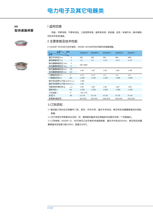
KK型 快速晶闸管 说明书
1 外形及安装尺寸
图1 SS11、SS12、SS13、SS14、SS15水冷平板型散热器件后的尺寸
H φg
d
φf L D
图2 KP20Y~KP500系列螺栓形普通晶闸管、KS20Y~KS200系列螺栓形双向晶闸管
H 门极引线 φf
d
φg φe 阴极辅助引线 L D
注:图2中KP50~KP500、KS50~KS200有辅助线,其他规格无此引线。
序号 1 2 3 4 5 6 7 8 9 10 型号 KS5、KP5 KS10、KP10 KS20、KP20 KS20Y、KP20Y KS30、KP30 KS50、KP50 KS100、KP100 KS200、KP200 KP300 KP500 通态平均电流IT(AV) A 5 10 20 20 30 50 100 200 300 500 H 11±1 11±1 11±1 11±1 13±1 13±1 16±1 19±1 19±1 27±1 L 30 39 39 165 170 175 200 225 225 300 d M6 M8 M10 M10 M12 M12 M16 M20 M20 M30 φg 3.2 4.2 4.2 6.5 6.5 7 8.4 9 9 15 φf 2 2 2 4.2 4.2 4.2 4.2 4.2 4.2 5.2 φe 4.2 4.2 4.2 5.2 D 16 22 22 28 31 37 37 48 48 58 S 14 19 19 24 27 32 32 42 42 50
断态电压临界上升率 dv/dt V/μs 通态电流临界上升率 di/dt A/μs 电路换向关断时间 tg 维持电流 IH 工作结温 Tj 紧固力 推荐散热器型号 μs mA ℃ kN
和利时LM可编程控制器硬件手册

如何使用手册 如果您需要了解PLC的硬件组成,请仔细阅读第1、2章。 如果您需要对本公司产品的技术规格、端子定义与接线示意图等内容有所了解,请参阅第2、 3章。 如果您需要了解安装、拆卸等原则,请仔细阅读第4章。附录A为LM系列小型PLC产品订货 清单。附录B为LM系列小型PLC通用技术规范。
CPU模块本身集成了一定数量的本机I/O点,其中一部分I/O点同时具有高速计数、高速输出 等功能。随着系统需求的扩大,将需要更多的I/O点数,通提出了一些PLC现场应用原则。
读者 《LM小型可编程控制器硬件手册》适用于有一定PLC背景知识的工程师、安装人员、技术 人员及电气人员。
HollySys Group
版权申明
本手册内容,包括文字、图表、标志、标识、商标、产品型号、软件程序、版面设计等, 均受《中华人民共和国著作权法》、《中华人民共和国商标法》、《中华人民共和国专利法》 及与之适用的国际公约中有关著作权、商标权、专利权或其他财产所有权法律的保护,为北京 和利时系统工程股份有限公司专属所有或持有。
内容 《LM小型可编程控制器硬件手册》是和利时公司对LM系列PLC产品从特性、技术规格等方 面进行详细介绍的技术手册,包含了LM小型PLC所有的硬件信息。
第1章从硬件体系结构、编程软件、快速应用等各个方面对LM小型PLC作了概述性介绍。
第2、3章主要针对CPU模块、扩展模块的技术规格、端子定义与接线示意图及等效电路进行 了详细阐述。
第 2 章 CPU 模块 ............................................................................................... 10
国华北京热电厂设备KKS编码(kks汽机部分)
国华北京热电厂设备KKS编码(暂行)设备部2000年6月一、设备KKS编码通则设备的KKS编码是目前世界上广为使用的一种设备编码方法,它采用的是国际标准,其目的是使每一个单位在不考虑语言文字和规定的情况下,对各种设备的职责范围进行统一的、无歧义的标识工作。
在我厂,同时用于TMMS计算机管理系统的识别功能。
1.编码的层次:KKS码通常由11-—16位字母与数字混合组成.按照系统及功能一般将整个编码分成四个层次。
1.1第一层:机组编号。
采用两位数字组成,第1—2位。
1.2第二层:系统编号.由三位字母和两位数字组成,第3—5位为字母,第6-7位为数字。
1.3第三层:设备编号。
由两位字母和三位数字组成,第8—9位为字母,第10-12位为数字.1.4第四层:元件编号。
由两位字母和两位数字组成,第13—14位为字母,第15-16位为数字。
(本次编码没有用到)2.编码方法:2.1 第一层:机组编号。
2.1.1 #1机编码为10;#2机编码为20;公用系统编码为00。
2。
1.2 对于一台机组对应的多于一套的成套设备,可在第二位表示出来,其排列顺序可按方位的编码原则加以编号。
2.1.3例:每台机有两台锅炉,#1炉可编码为“11”;#2炉可编码为“12”。
顺序按自西向东的原则。
2.2第二层:系统编号.2.2.1 第3-5位字母编码是系统的分类名称,已经有现成的系统编码名称清册,编码时直接套用即可。
2。
2。
2第6-7位是数字编码,表示在本系统内再细分子系统或小系统以及系统内装置或再分段的顺序排列。
具体的排列原则如下:①自西向东的原则;②自南向北的原则;③自下而上的原则;④形成回路时,可按介质流向的原则;⑤凡形成回路时,如四角布置的喷燃器等,以西南角定义为起点,按顺时针方向排列。
⑥未形成回路的情况,上述各原则的优先顺序如下:介质流向//自下而上//自西向东//自南向北注:上述原则是一位数字排列顺序的原则,不可同时用于两位数字的排列,编码时先要定义好两位数字各自的含义,先排十进位上的数,再排个位上的数,组合后将设备系统界定。
科尼变频器中英文手册
3.1 Control keypad operation 控制显示屏操作 .................................................................. 23 3.1.1 Navigation on the control keypad 控制显示屏演示 ......................................... 25 3.1.2 Value line editing 数值的编辑........................................................................ 25 3.1.3 Passwords 密码 ........................................................................................... 26 3.1.4 Monitoring 监控 .......................................................................................... 287
8. Do not touch the components on the circuit boards. Static voltage discharge may cause damage or destroy the IC-circuits. 不要用手接触电路板的元器件.系统的固有电压放电可能会损坏 IC 电路.
欧诺克 直流伺服电机 产品说明书

深圳市欧诺克科技有限公司Shenzhen ONKE Technology Co., Ltd.座机:*************27381841电话:邓先生135****7106陈先生139****0920邮箱:***************网 址 : 地址:广东省深圳市宝安区福海街道怀德翠湖工业园13栋稳定的质量是我们赖以生存的根本优质的服务是我们继续发展的前提客户的满意是我们唯一追求的目标产品画册Product gallery专业生产伺服驱动器、伺服电机及自动化控制系统深圳市欧诺克科技有限公司直流伺服电机目录匠心制造精益求精“一、公司介绍01二、直流伺服电机021.电机介绍与型号说明032.电机应用领域043.电机规格参数表054.电机规格尺寸图06C O M P A N Y PROFILE以精密制造引领未来Leading the future with precision manufacturing公司简介Company Profile深圳市欧诺克科技有限公司成立于2010年,是一家专业研发生产伺服电机和驱动器的高新技术企业,公司技术力量雄厚,检测手段先进,欧诺克人本着不求最全,只求最精的信念,为生产出各类伺服电机、各类驱动器而不懈奋斗。
欧诺克人以鹰的精神,挑战尖端,研发生产出高性价比的各类伺服电机和驱动器,以鹰的敏锐洞察力洞察市场,与时俱进、创新来满足市场的需求。
深圳市欧诺克科技有限公司产品主要有:伺服驱动器、伺服电机、直流伺服驱动器,直流伺服电机,交流伺服驱动器,交流伺服电机,低压伺服驱动器,低压伺服电机,直线电机驱动器,DDR马达驱动器,音圈电机驱动器,直流无刷驱动器,直流无刷电机,CANopen总线、EtherCAT总线、电子凸轮伺服系统,大功率伺服驱动器、大电流伺服驱动器,专用运动控制伺服驱动器和自动化控制系统,十多年来凭借精湛的技术与国内国外众多知名企业公司建立了互利共赢的合作。
公司不断研究和开发满足行业需求的各类伺服电机和驱动器,帮助客户提升品质和生产效率。
ioLogik设备说明书
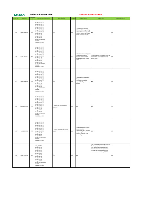
ioLogik W5340
ioLogik W5340-HSPA
NA-4010
NA-4020/NA-4021
Change(s)
Software Name: ioAdmin
Enhancement(s)
Bug(s) Fixed
Additional Note(s)
1. Using new installshield
E2200 series
1. Support MOXA green core
design
N/A
2. W5340-HSPA Model supports SMTP port number
N/A
N/A
changing
ioLogik E2210 (-T)
ioLogik E2212 (-T)
ioLogik E2214 (-T)
N/A
ioLogik E2262 (-T) ioLogik R2110
N/A
ioLogik R2140
ioLogik W5312
ioLogik W5340
ioLogik W5340-HSPA
NA-4010
NA-4020/NA-4021
ioLogik E2210 (-T)
ioLogik E2212 (-T)
NA-4020/NA-4021
New Feature(s)
ioLogik E2210 (-T)
ioLogik E2212 (-T)
ioLogik E2214 (-T)
ioLogik E2240 (-T)
ioLogik E2242 (-T)
ioLogik E2260 (-T)
3.18
Build16022511
奔克电梯主板2005版现场调试手册 正文

BP系列电梯控制系统技术手册
现场调试手册 目录 表示在本手册中
1 公司宗旨 ............................................................................................................ 8
2 技术特点 ............................................................................................................ 9
2.1 硬件 ........................................................................................................................................... 9 2.1.1 bp300/bp302/bp304/306标准配置 ................................................................................... 9 2.1.2 bp系列控制系统的优点和选项........................................................................................... 9
3.6.6 DCS-422A串行扩展 CSBK-01并行扩展以及bp300并联控制 ....................................... 32 3.6.7 CWG-02井道信号采集器................................................................................................. 34 3.6.8 群控接口板GRN-01和群控连接方法............................................... 39 3.6.9 串行外召板SCD .............................................................................................................. 40 3.6.10 宽带网络接入器NETCOM ............................................................................................... 41 3.6.11 IC卡智能呼梯系统 ........................................................................................................... 42 3.6.12 壁挂式召唤盒BX-01系列 ................................................................................................. 42 3.7 bp控制系统的配置方案............................................................................................................ 43
HL-1说明书
HL-1 开发板使用说明书 慧净电子-做人人都买得起的 51 单片机开发板
3.6 利用定时器和蜂鸣器唱歌.......................................................................... 3.7 模数转换 ADC 的应用......................................................................... 3.8 继电器的应用........................................................................ 3.9 DS18B20 温度测量显示实验...................................................................... 3.10 1602 字符液晶显示................................................................................... 3.11 EEPROM AT24C02 实验......................................................................... 3.12 串口通讯实验............................................................................................ 联系方式...................................................................................................................
海伦 Моллер PKZM0 电机保护电路保护器说明书
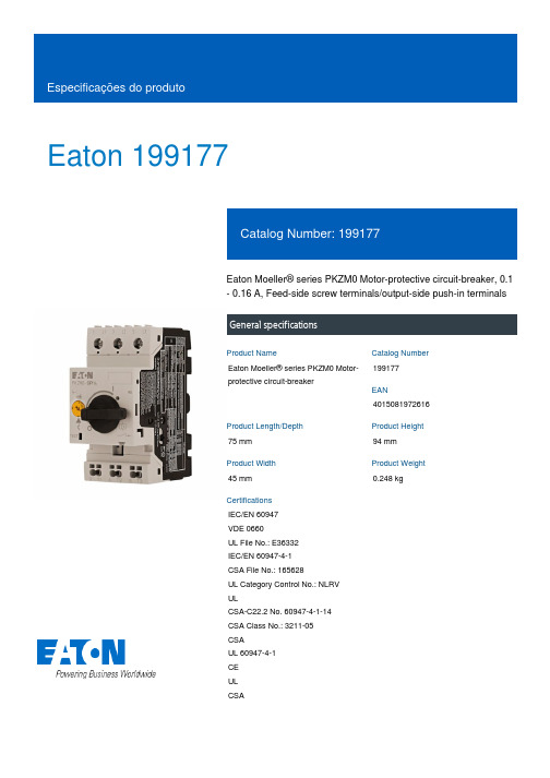
Eaton 199177Eaton Moeller® series PKZM0 Motor-protective circuit-breaker, 0.1 - 0.16 A, Feed-side screw terminals/output-side push-in terminalsGeneral specificationsEaton Moeller® series PKZM0 Motor-protective circuit-breaker199177401508197261675 mm 94 mm 45 mm 0.248 kgIEC/EN 60947 VDE 0660UL File No.: E36332 IEC/EN 60947-4-1 CSA File No.: 165628UL Category Control No.: NLRV ULCSA-C22.2 No. 60947-4-1-14 CSA Class No.: 3211-05 CSAUL 60947-4-1 CE UL CSAProduct NameCatalog Number EANProduct Length/Depth Product Height Product Width Product Weight CertificationsTurn buttonPhase-failure sensitivity (according to IEC/EN 60947-4-1, VDE 0660 Part 102)Phase failure sensitiveMotor protectionThree-pole 100,000 operations100,000 OperationsDIN rail (top hat rail) mounting optionalCan be snapped on to IEC/EN 60715 top-hat rail with 7.5 or15 mm height.40 Operations/hIII3Motor protective circuit breakerFinger and back-of-hand proof, Protection against direct contact when actuated from front (EN 50274)6000 V AC25 g, Mechanical, according to IEC/EN 60068-2-27, Half-sinusoidal shock 10 msAlso motors with efficiency class IE3Branch circuit: Manual type E if used with terminal, or suitable for group installations, (UL/CSA)-25 - 55 °C, Operating range≤ 0.25 %/K, residual error for T > 40°-5 - 40 °C to IEC/EN 60947, VDE 0660Actuator type Features Functions Number of poles Lifespan, electricalLifespan, mechanicalMounting MethodMounting positionOperating frequencyOvervoltage categoryPollution degreeProduct categoryProtectionRated impulse withstand voltage (Uimp) Shock resistanceSuitable forTemperature compensationAltitude Terminal capacity (flexible with ferrule)Max. 2000 m-25 °C55 °C-25 °C40 °C-40 °C80 °CDamp heat, constant, to IEC 60068-2-78 Damp heat, cyclic, to IEC 60068-2-301 x (1 - 6) mm², Screw terminals2 x (1 - 6) mm², Screw terminals1 x (0.5 - 2.5) mm², Push-in terminals, ferrule to DIN 46228-12 x (0.5 - 2.5) mm², Push-in terminals, ferrule to DIN 46228-11 x (0.5 - 1.5) mm², Push-in terminals, ferrule to DIN 46228-42 x (0.5 - 1.5) mm², Push-in terminals, ferrule to DIN 46228-41 x (0.5 - 2.5) mm², Push-in terminals2 x (0.5 - 2.5) mm², Push-in terminals1 x (0.5 - 2.5) mm², Push-in terminals2 x (0.5 - 2.5) mm², Push-in terminals18 - 10, screw terminals20 - 14, Push-in terminals10 mm1.7 Nm, Screw terminals, Main cable50 Hz 60 Hz 0.16 A 0 kW 0 kW 690 V 690 V 0.16 A 50 kA, 600 Y/347 V, SCCR (UL/CSA) 65 kA, 240 V, SCCR (UL/CSA)65 kA, 480 Y/277 V, SCCR (UL/CSA)Basic device fixed 15.5 x Iu, Trip Blocks ± 20% tolerance, Trip blocks2.5 A, Irm, Setting range max.5 HPPush-in terminals on output side Screw terminals on feed sideAmbient operating temperature - min Ambient operating temperature - maxAmbient operating temperature (enclosed) - min Ambient operating temperature (enclosed) - max Ambient storage temperature - minAmbient storage temperature - maxClimatic proofing Terminal capacity (flexible)Terminal capacity (solid)Terminal capacity (solid/stranded AWG) Stripping length (main cable) Tightening torqueRated frequency - minRated frequency - maxRated operational current (Ie)Rated operational power at AC-3, 220/230 V, 50 Hz Rated operational power at AC-3, 380/400 V, 50 Hz Rated operational voltage (Ue) - minRated operational voltage (Ue) - maxRated uninterrupted current (Iu)Short-circuit current rating (type E)Short-circuit releaseAssigned motor power at 230/240 V, 60 Hz, 1-phase Connection0 0 00.16 A0.16 AOverload trigger: tripping class 10 A5.39 W0 W0 W0 WMeets the product standard's requirements.Meets the product standard's requirements.Meets the product standard's requirements.Meets the product standard's requirements.Meets the product standard's requirements.Does not apply, since the entire switchgear needs to be evaluated.Does not apply, since the entire switchgear needs to be evaluated.Meets the product standard's requirements.DA-DC-00004888.pdfDA-DC-00004918.pdfeaton-manual-motor-starters-pkzm-pkzm0-dimensions-002.eps 121X042121X002eaton-manual-motor-starters-pkz-dimensions.epseaton-manual-motor-starters-pkz-dimensions-002.epsETN.PKZM0-0,16-SPI16.edzIL03407011Zpkzm0_s16_pi.dwgpkzm0_s16_pi.stpNumber of auxiliary contacts (change-over contacts) Number of auxiliary contacts (normally closed contacts) Number of auxiliary contacts (normally open contacts)Overload release current setting - min Overload release current setting - max Tripping characteristicEquipment heat dissipation, current-dependent PvidHeat dissipation capacity PdissHeat dissipation per pole, current-dependent PvidStatic heat dissipation, non-current-dependent Pvs10.2.2 Corrosion resistance10.2.3.1 Verification of thermal stability of enclosures10.2.3.2 Verification of resistance of insulating materials to normal heat10.2.3.3 Resist. of insul. mat. to abnormal heat/fire by internal elect. effects10.2.4 Resistance to ultra-violet (UV) radiation10.2.5 Lifting10.2.6 Mechanical impact10.2.7 Inscriptions Declarations of conformity DesenhoseCAD modelInstruções de instalação mCAD model10.3 Degree of protection of assembliesDoes not apply, since the entire switchgear needs to be evaluated.10.4 Clearances and creepage distancesMeets the product standard's requirements.10.5 Protection against electric shockDoes not apply, since the entire switchgear needs to be evaluated.10.6 Incorporation of switching devices and componentsDoes not apply, since the entire switchgear needs to be evaluated.10.7 Internal electrical circuits and connectionsIs the panel builder's responsibility.10.8 Connections for external conductorsIs the panel builder's responsibility.10.9.2 Power-frequency electric strengthIs the panel builder's responsibility.10.9.3 Impulse withstand voltageIs the panel builder's responsibility.10.9.4 Testing of enclosures made of insulating materialIs the panel builder's responsibility.10.10 Temperature riseThe panel builder is responsible for the temperature rise calculation. Eaton will provide heat dissipation data for the devices.10.11 Short-circuit ratingIs the panel builder's responsibility. The specifications for the switchgear must be observed.10.12 Electromagnetic compatibilityIs the panel builder's responsibility. The specifications for the switchgear must be observed.10.13 Mechanical functionThe device meets the requirements, provided the information in the instruction leaflet (IL) is observed.Eaton Corporation plc Eaton House30 Pembroke Road Dublin 4, Ireland © 2023 Eaton. Todos os direitos reservados. Eaton is a registered trademark.All other trademarks areproperty of their respectiveowners./socialmedia。
SCHUNK 抓取模块产品参数表说明书
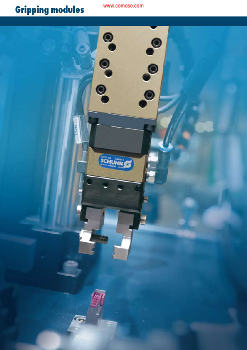
Gripping modules w w w .s c h u n k .c o m 1892-finger gripper for small components2-fi nger universalgripper withmulti-tooth guide3-finger universalgripper withmulti-tooth guide2-fi nger radialgripper, GWB2-fi nger universal gripper,PowerCube system 2-fi nger gripper for small components,MEGSpecial gripper 2-fi nger clean-room gripper, DKG-RR O-ring gripper for external andinternal assemblyGripping modules2-fi nger parallel grippers19019419619820085204105206205208210122141621820222282263-fi nger centric gripper23012234162382024228246Angular gripper 25012254162582026228266Angle parallel gripper 270280274300278400282SCHUNK offers you the most extensive program of gripping modules.From pneumatically or electrically driven grippers to small-component, universal, and long-stroke grippers and industry-specific gripping solutions. Please consult our main catalog for further information about SCHUNK gripping modules. Here is an extract from our range of products.G R I P P I N G M O D U L E Sw w w .s c h u n k .c o m190 Short-stroke gripper for small componentsSizes80/81 .. 200/201Mass0.32 kg .. 1.75 kg Gripping force 120 N .. 600 N Stroke per finger 2.5 mm .. 10 mmWorkpiece weight, force-fit gripping Up to 3.0 kgApplication examplePneumatic pick & place unit with additional third vertical position and workpiece turning1 Double socket, SOD 0552 Hollow pillar, SLH 055-05003 Double mounting plate, APDH 0854 Linear module, LM 200-H1505 Reinforcing bracket, VW 1006 Linear module with intermediate stop,LM 100-H175-ZZA101-H507Adapter plate, APL 1208Rotary module, RM 110-W090-2 9Parallel gripping module, GM 101-KGM1223456789Short-stroke gripper for small components Short-stroke gripper for small componentsArea of applicationAdvantages – your benefitsGeneral information about the seriesWorking principleWedge-hook kinematicsHousing materialAluminum alloy, hard-anodizedGuidanceCircular guide, ground and hardenedActuationPneumatic, via filtered compressed air (10 μm): dry, lubricated, or non-lubricated Pressurizing medium: requirements for compressed air quality class according to DIN ISO 8573-1: Quality class 4Scope of deliveryCompletely ready for operationwithout bracket for proximity switch and without proximity switch Warranty24 monthsGripping force retaining deviceCan be integrated without additional interfering contour in the standard gripper2-finger parallel grippers with circular guideGriping and moving small to medium workpieces in low-contami-nation areas; for example, in assembly, testing, labs, pharmaceuti-cals, and many others.Compact designFor minimum interfering contours in useRound rod guidance of the base jawsFor excellent guidance characteristicsSpecial set screwsFor the limiting of the adjustable stroke in both directions Integration of a gripping force safety device without additional parts is optionalFor firm grip even in the event of power failureEnd-position monitoringUsing an optional standardized monitoring set Standardized mounting boresFor numerous combinations with other GEMOTEC system elementsGM For production reasons, the colors may vary from those shown in the catalog. w w w.s c h u n k.c o m191w w w .s c h u n k .c o m192The application of pressure to the opposite piston surfaces guides the movement through a connecting member to the base jaws.Description of functionThis module can be combined as standard with many elements from the modular system. You can find more information in the “Accessories” chapter.Options and special informationCross-section of function1 Circular guideSimple and yet non-elastic 2 Stroke limitationFor limiting the opening or closing stroke3 DriveNo piston rod, so the effective surface is thesame in both directions4 Modular design hole patternCompletely integrated in the module system5 Kinematics Inside, power transmission via line contact6 Base jawsFor adaptation of the workpiece-specific gripper fingersShort-stroke gripper for small componentsGMw w w .s c h u n k .c o m 193AccessoriesP lease see the side views at the end of the respective size for information concerning specific sizes, accessories availability for that size, designation, and ID numbers. You can find more information about our accessories program in the “Accessories” part of the catalog.General information about the seriesGripping forceThis is the arithmetic sum of the gripping forces applied to each claw jaw, measured at a distance of 20 mm from the upper edge of the gripper.Finger lengthThe finger length is measured from the upper edge of the base jaw in the direction of the main axis.Repeat accuracyThis is defined as the distribution of the end positions of 100 successive strokes.Workpiece weightThe recommended workpiece weight is calculated for friction grip with a coefficient of static friction of 0.1 and a safety factor of 2 against workpiece slippage at acceleration due to gravity only. For form-fit or capture gripping, there are significantly higher permissible workpiece weights.Closing and opening timesClosing and opening times are only movement times of the base jaws or fingers. Valve switching times, hose filling times, or PLC reaction times are not a part of this and are to be considered when cycle times are calculated.Short-stroke gripper for small componentsGMFittingsSensor cableCentering strips Pressure maintenance valveAdapter platesInductive proximity switch, NIPillar assembly systemsw w w .s c h u n k .c o m194Finger loadTechnical dataM oments and forces apply per base jaw and may oc-cur among themselves at the same time. M y may occur additionally to the moment produced by the gripping force itself.Short-stroke gripper for small componentsGM 80/81DesignationGM 80GM 81GM 80-K GM 81-K GM 80-S GM 81-S ID 031306003130630313062031306503130610313064Stroke per jaw [mm] 2.5 4.5 2.5 4.5 2.5 4.5Closing grip force [N]200120260150Opening grip force[N]200120260150Min. grip force applied by spring [N]60306030Mass[kg]0.320.320.320.320.320.32Recommended workpiece weight [kg] 1.00.6 1.00.6 1.00.6Fluid consumption for double stroke [cm³] 3.86 3.86 3.86 3.86 3.86 3.86Minimum pressure [bar]33 4.5 4.5 4.5 4.5Maximum pressure[bar]888888Nominal operating pressure [bar]666666Closing time [s]0.020.020.0150.0150.0250.025Opening time[s]0.020.020.0250.0250.0150.015Max. permissible finger length [mm]505050505050IP rating404040404040Min. ambient temperature [°C]555555Max. ambient temperature [°C]606060606060Repeat accuracy[mm]± 0.02± 0.02± 0.02± 0.02± 0.02± 0.02Gripping force, I.D. grippingGripping force, O.D. grippingw w w .s c h u n k .c o m195Main viewsA, a Main and direct connections, gripper open B, b Main and direct connections, gripper close Gripper connection Finger connection on both sidesNot included in the scope of delivery Set screw for stroke limitationShort-stroke gripper for small componentsGM 80/81Sensor systemsEnd-position monitoring:Inductive proximity switch, can be directly mounted Designation IDScope of deliveryRecommended productGMNS 50-X 0313339Bracket, sensorGMNS 50-G 0313340Bracket, sensor, straight cableextension•GMNS 50-W0313341Bracket, sensor, angled cableextensionT wo sensors are needed for each gripperYou can find further information and components for the accessories mentioned here in the “Accessories” part of the catalog.w w w .s c h u n k .c o m196Technical dataShort-stroke gripper for small componentsGM 100/101Finger loadM oments and forces apply per base jaw and may oc-cur among themselves at the same time. M y may occur additionally to the moment produced by the gripping force itself.DesignationGM 100GM 101GM 100-K GM 101-K GM 100-S GM 101-S ID 031306903130720313071031307403130700313073Stroke per jaw [mm]474747Closing grip force [N]300160410220Opening grip force[N]300160410220Min. grip force applied by spring [N]1106011060Mass[kg]0.620.620.620.620.620.62Recommended workpiece weight [kg] 1.50.8 1.50.8 1.50.8Fluid consumption for double stroke [cm³]9.789.789.789.789.789.78Minimum pressure [bar]33 4.5 4.5 4.5 4.5Maximum pressure[bar]888888Nominal operating pressure [bar]666666Closing time [s]0.030.030.0250.0250.040.04Opening time[s]0.030.030.040.040.0250.025Max. permissible finger length [mm]707070707070IP rating404040404040Min. ambient temperature [°C]555555Max. ambient temperature [°C]606060606060Repeat accuracy[mm]± 0.02± 0.02± 0.02± 0.02± 0.02± 0.02Gripping force, I.D. grippingGripping force, O.D. grippingw w w .s c h u n k .c o m197Short-stroke gripper for small componentsGM 100/101Main viewsA, a Main and direct connections, gripper open B, b Main and direct connections, gripper close Gripper connection Finger connection on both sidesNot included in the scope of delivery Set screw for stroke limitationSensor systemsEnd-position monitoring:Inductive proximity switch, can be directly mounted Designation IDScope of deliveryRecommended productGMNS 100-X 0313342Bracket, sensorGMNS 100-G 0313343Bracket, sensor, straight cableextension•GMNS 100-W0313344Bracket, sensor, angled cableextensionT wo sensors are needed for each gripperYou can find further information and components for the accessories mentioned here in the “Accessories” part of the catalog.w w w .s c h u n k .c o m198Technical dataShort-stroke gripper for small componentsGM 200/201M oments and forces apply per base jaw and may oc-cur among themselves at the same time. M y may occur additionally to the moment produced by the gripping force itself.DesignationGM 200GM 201GM 200-K GM 201-K GM 200-S GM 201-S ID 031307803130810313080031308303130790313082Stroke per jaw [mm]610610610Closing grip force [N]600340740410Opening grip force[N]600340740410Min. grip force applied by spring [N]1407014070Mass[kg] 1.75 1.75 1.75 1.75 1.75 1.75Recommended workpiece weight [kg] 3.0 1.7 3.0 1.7 3.0 1.7Fluid consumption for double stroke [cm³]25.8825.8825.8825.8825.8825.88Minimum pressure [bar]33 4.5 4.5 4.5 4.5Maximum pressure[bar]888888Nominal operating pressure [bar]666666Closing time [s]0.050.050.040.040.060.06Opening time[s]0.050.050.060.060.040.04Max. permissible finger length [mm]100100100100100100IP rating404040404040Min. ambient temperature [°C]555555Max. ambient temperature [°C]606060606060Repeat accuracy[mm]± 0.02± 0.02± 0.02± 0.02± 0.02± 0.02Gripping force, I.D. grippingGripping force, O.D. grippingw w w .s c h u n k .c o m199Short-stroke gripper for small componentsGM 200/201Main viewsA, a Main and direct connections, gripper open B, b Main and direct connections, gripper close Gripper connection Finger connection on both sidesNot included in the scope of deliverySet screw for stroke limitationSensor systemsEnd-position monitoring:Inductive proximity switch, can be directly mounted Designation IDScope of deliveryRecommended productGMNS 200-X 0313345Bracket, sensorGMNS 200-G 0313346Bracket, sensor, straight cableextension•GMNS 200-W0313347Bracket, sensor, angled cableextensionT wo sensors are needed for each gripperYou can find further information and components for the accessories mentioned here in the “Accessories” part of the catalog.。
HLMP-K105-KN001中文资料

AgilentT-13/4 (5 mm), T-1 (3 mm),High Intensity, Double Heterojunction AlGaAs Red LED LampsData SheetHLMP-D101/D105, HLMP-K101/K105DescriptionThese solid state LED lamps utilize newly developed doubleheterojunction (DH) AlGaAs/GaAs material technology. This LED material has outstanding lightoutput efficiency over a wide rangeFeatures• Exceptional brightness • Wide viewing angle• Outstanding material efficiency • Low forward voltage • CMOS/MOS compatible • TTL compatible • Deep red colorApplications• Bright ambient lighting conditions • Moving message panels • Portable equipment • General useof drive currents. The color is deep red at the dominantwavelength of 637 nanometres.These lamps may be DC or pulse driven to achieve desired light output.Package DimensionsA B CSelection GuideLuminous IntensityIv (mcd) at 20 mA2θ1/2[1]Package Package Description Device HLMP-Min.Typ.Max.Degree Outline T-1 3/4 Red Tinted Diffused D10135.270.0–65AD101-J00xx35.270.0–65AD101-JK0xx35.270.0112.865AT-1 3/4 Red Untinted Non-diffused D105138.0240.0–24BD105-M00xx138.0240.0–24BD105-NO0xx200.0290.0580.024BT-1 Red Tinted Diffused K10122.045.0–60CK101-100xx22.045.0–60CK101-IJ0xx22.045.070.460CT-1 Red Untinted Non-diffused K10535.265.0–45CK105-J00xx35.265.0–45CK105-KL0xx56.4110.0180.445CNote:1. θ1/2 is the off axis angle from lamp centerline where the luminous intensity is 1/2 the on-axis value.Part Numbering SystemHLMP - x x xx - x x x xxMechanical Option00: Bulk01: Tape & Reel, Crimped Leads02: Tape & Reel, Straight LeadsA1: Right Angle Housing, Uneven Leads, T1A2: Right Angle Housing, Even Leads, T1B1: Right Angle Housing, Uneven Leads, T-1 3/4B2: Right Angle Housing, Even Leads, T-1 3/4DD, UQ: Ammo PackColor Bin Options0: Full Color Bin DistributionMaximum Iv Bin Options0: Open (no max. limit)Others: Please refer to the Iv Bin TableMinimum Iv Bin OptionsPlease refer to the Iv Bin TableLens Type01: Tinted, Diffused05: Untinted, NondiffusedColor Options1: AlGaAs RedPackage OptionsD: T-1 3/4K: T-1Absolute Maximum Ratings at T A = 25°CParameter ValuePeak Forward Current[1,2]300 mAAverage Forward Current[2]20 mADC Current[3]30 mAPower Dissipation87 mWReverse Voltage (I R = 100 µA) 5 VTransient Forward Current (10 µs Pulse)[4]500 mALED Junction Temperature110°COperating Temperature Range-20 to +100°C Storage Temperature Range-55 to +100°C Wave Soldering Temperature [1.59 mm (0.063 in.) from body]250°C for 3 seconds Lead Solder Dipping Temperature [1.59 mm (0.063 in.) from body]260°C for 5 seconds Notes:1.Maximum I PEAK at f = 1 kHz, DF = 6.7%.2.Refer to Figure 6 to establish pulsed operating conditions.3.Derate linearly as shown in Figure 5.4.The transient peak current is the maximum non-recurring peak current the device can withstand without damaging the LED die and wire bonds. It isnot recommended that the device be operated at peak currents beyond the Absolute Maximum Peak Forward Current.Electrical/Optical Characteristics at T A = 25°CSymbol Description Min.Typ.Max.Unit Test ConditionV F Forward Voltage 1.8 2.2V I F = 20 mAV R Reverse Breakdown Voltage 5.015.0V I R = 100 µAλp Peak Wavelength645nm Measurement at Peakλd Dominant Wavelength637nm Note 1∆λ1/2Spectral Line Halfwidth20nmτS Speed of Response30ns Exponential TimeConstant, e-t/T SC Capacitance30pF V F = 0, f = 1 MHzRθJ-PIN Thermal Resistance260[3]°C/W Junction to Cathode Lead210[4]290[5]ηV Luminous Efficacy80Im/W Note 2Notes:1.The dominant wavelength, λd, is derived from the CIE chromaticity diagram and represents the color of the device.2.The radiant intensity, I e, in watts per steradian, may be found from the equation I e = l V/ηV, where I V is the luminous intensity in candelas and ηV isluminous efficacy in lumens/watt.3.HLMP-D101.4.HLMP-D105.5.HLMP-K101/-K105.Figure 3. Relative luminous intensity vs. dc forward current.Figure 4. Relative efficiency vs. peak forward current.Figure 7. Relative luminous intensity vs. angular displacement. HLMP-D101.Figure 8. Relative luminous intensity vs. angular displacement. HLMP-K101.Intensity Bin LimitsIntensity Range (mcd)Color Bin Min.Max.Red I24.839.6J39.663.4K63.4101.5L101.5162.4M162.4234.6N234.6340.0O340.0540.0P540.0850.0Q850.01200.0R1200.01700.0S1700.02400.0T2400.03400.0U3400.04900.0V4900.07100.0W7100.010200.0X10200.014800.0Y14800.021400.0Z21400.030900.0Maximum tolerance for each bin limit is ± 18%.Mechanical Option MatrixMechanical Option Code Definition00Bulk Packaging, minimum increment 500 pcs/bag01Tape & Reel, crimped leads, minimum increment 1300 pcs (T-1 3/4)/1800 pcs (T-1) 02Tape & Reel, straight leads, minimum increment 1300 pcs (T-1 3/4)/1800 pcs (T-1) A1Right Angle Housing, uneven leads, minimum increment 500 pcs/bagA2Right Angle Housing, even leads, minimum increment 500 pcs/bagB1Right Angle Housing, uneven leads, minimum increment 500 pcs/bagB2Right Angle Housing, even leads, minimum increment 500 pcs/bagDD Ammo Pack, straight leads in 2K incrementUQ Ammo Pack, horizontal leads in 2K incrementNote:All categories are established for classification of products. Products may not be available in all categories. Please contact your local Agilent representative for further clarification/information./semiconductors For product information and a complete list of distributors, please go to our web site.For technical assistance call:Americas/Canada: +1 (800) 235-0312 or (916) 788-6763Europe: +49 (0) 6441 92460China: 10800 650 0017Hong Kong: (+65) 6756 2394India, Australia, New Zealand: (+65) 6755 1939 Japan: (+81 3) 3335-8152 (Domestic/Interna-tional), or 0120-61-1280 (Domestic Only) Korea: (+65) 6755 1989Singapore, Malaysia, Vietnam, Thailand, Philippines, Indonesia: (+65) 6755 2044 Taiwan: (+65) 6755 1843Data subject to change.Copyright © 2004 Agilent Technologies, Inc. Obsoletes 5968-1440ENovember 12, 20045988-2230EN。
K5 PLC硬件使用手册201908
目录第一部分 (6)第一章系统通用说明 (7)1.1产品应用范围 (7)1.2本文常用名称 (7)1.3产品命名规则 (9)1.3.1产品名称说明 (9)1.3.2订货号说明 (12)1.4K INCO-K5系列PLC产品列表 (13)第二部分 (16)第一章KINCO-K5系列PLC应用 (17)1.1产品体系结构 (17)1.1.1概述 (17)1.1.2单机最大规模 (17)1.1.3通讯网络 (18)1.2系统电源设计 (19)1.2.1集成电源概述 (19)1.2.2DC24V输出电源核算 (19)1.2.3扩展电源核算 (20)1.2.4CPU模块输入功率 (21)1.3正常的工作条件 (22)第二章CPU原理及应用 (23)2.1概述 (23)2.1.1部件结构图 (23)12.2各部分功能介绍 (25)2.2.1CPU状态及指示灯 (25)2.2.2串行通信口 (26)2.2.3数据保持和数据备份 (26)2.2.4实时时钟(RTC) (27)2.2.5高速脉冲计数和高速脉冲输出 (27)2.2.6边沿中断 (27)2.3接线图 (28)2.4技术数据 (38)第三章DI扩展模块 (41)3.1DI8×DC24V (41)3.1.1接线图 (41)3.1.2技术数据 (42)3.2DI16×DC24V (43)3.2.1接线图 (43)3.2.2技术数据 (44)第四章DO扩展模块 (45)4.1DO8×DC24V (45)4.1.1接线图 (45)4.1.2技术数据 (46)4.2DO8×继电器 (47)4.2.1接线图 (47)4.2.2技术数据 (48)4.3DO16×DC24V (49)4.3.1接线图 (49)24.4DO16×继电器 (51)4.4.1接线图 (51)4.4.2技术数据 (52)第五章DI/O扩展模块 (53)5.1DI/O,DI4×DC24V DO4×DC24V (53)5.1.1端子接线图 (53)5.1.2技术数据 (54)5.2DI/O,DI4×DC24V DO4×继电器 (55)5.2.1端子接线图 (55)5.2.2技术数据 (56)5.3DI/O,DI8×DC24V DO8×DC24V (57)5.3.1端子接线图 (57)5.3.2技术数据 (58)5.4DI/O,DI8×DC24V DO8×继电器 (59)5.4.1端子接线图 (59)5.4.2技术数据 (60)第六章AI扩展模块 (61)6.1AI4×IV,电流/电压输入 (61)6.1.1端子接线图 (61)6.1.2测量范围和测量值表示格式 (61)6.1.3技术数据 (62)6.2AI4×RD,热电阻输入 (63)6.2.1端子接线图 (63)6.2.2测量范围和测量值表示格式 (63)6.2.3技术数据 (64)36.3.1端子接线图 (65)6.3.2测量范围和测量值表示格式 (65)6.3.3技术数据 (66)第七章AO扩展模块 (67)7.1AO2×IV,电流/电压输出 (67)7.1.1端子接线图 (67)7.1.2输出范围和输出值表示格式 (67)7.1.3技术数据 (68)第八章AI/O扩展模块 (69)8.1AI/O,AI2×IV AO2×IV,电流/电压输入/输出 (69)8.1.1端子接线图 (69)8.1.2AI测量范围和测量值表示格式 (70)8.1.3AO输出范围和输出值表示格式 (70)8.1.4技术数据 (71)第九章扩展功能模块 (72)9.1K541CAN通信模块 (72)9.1.1主要特点 (72)9.1.2端子和指示灯说明 (73)9.1.3接线示意图 (74)9.1.4技术数据 (74)9.2PS580扩展电源模块 (75)9.2.1主要特点 (75)9.2.2PS580使用示意图 (76)9.2.3PS580应用示例 (76)9.2.4技术数据 (78)4第十章安装及接线 (79)10.1模块外形尺寸 (79)10.2模块的连接 (80)10.3模块的安装 (81)10.4接线端子的拆卸和安装 (83)10.4.1端子排的拆卸 (83)10.4.2端子排的重新安装 (83)10.5保护电路和接地 (84)10.5.1晶体管型DO通道的保护功能 (84)10.5.2继电器型DO通道的外部保护指南 (84)10.5.3接地 (85)5第一部分通用说明6第一章系统通用说明1.1产品应用范围按照公认的PLC分类规则,Kinco-K5系列PLC属于小型一体化PLC,因此适用于工厂自动化领域中的机器控制和小规模过程控制。
智能LED控制和光源电路的5050大小包装产品说明书
Instruction ManualILPL-K501-RGBW-SK105-01Product OverviewThe ILPL-K501-RGBW-SK105-01 is an Intelligent LED with control and light emitting circuit, all contained in a 5050 sized package.Based on the industry standard SK6182 device, the control circuit consists of signal shaping amplification, built-in constant current source, and a high precision RC oscillator.The data protocol being used is the unipolar NRZ communication mode, where the 32-bit data is transmitted from the controller to DIN of the first LED, after an internal data latch, the remaining data is passed through the internal amplification circuit and sent out of the DO port to the remaining pixels. Using ‘automatic shaping forwarding technology’ means the number of cascaded LEDs is only limited by the signal transmission speed.Applicationsz Task Lightingz Back Lightingz Desk Lightingz Garage Lightingz Accent Lightingz Under Cabinet Lightingz Bar Lightingz Refrigerationz Industrial Applicationsz PhotographyTechnical Featuresz Control circuit and the RGBW die all in one 5050 sized devicez Grey level adjusting control (256 level grey scale)z Red drive special control enhances colour balancez Transmission distance between two points can be up to 10Mz Using a typical data transmission frequency of 800 Kbps, you can achieve refresh rates of 30 frames per secTechnical Drawing (mm)Notes:1. All dimensions are in millimeters.2. Tolerance is ±0.1mm unless otherwise notedPIN configurationAbsolute Maximum Ratings (Ta=25˚,VSS=0V)The electrical parameters (unless otherwise specified, TA=-20 - +70˚C, VDD=4.5 - 5.5V, VSS=0V)The dynamic parameters (Ta=25˚C)The data transmission time (TH+TL=1.25μs±600ns)T0H0 code, high level time0.3μs±0.15μs T0L0 code, low level time0.9μs±0.15μs T1H 1 code, high level time0.6μs±0.15μs T1L 1 code, low level time0.6μs±0.15μs Trst Reset code, low level time80μsTiming waveformmode:ConnectionInputcode:The method of data transmissionThe data structure of 24bitNote: high starting, in order to send data (R7 - R6 - ...... ..W0) The typical application circuit:CIE chromaticity coordinates (ANSI Natural white)ANSI Warm White Color bin structuresStandard LED Performance Graph1020%0.0040%60%80%Forward Current(mA)Forward Voltage(V) Tj=25 °CN o r m a l i z e d L u m i n o u s F l u xF o r w a r dC u r r e n t (m A )Typical Relative Luminous Flux vs. Forward CurrentForward Voltage vs. Forward Current12040608010020%0.0040%60%80%Thermal Pad Temperature (T=25°C)N o r m a l i z e dL u m i n o u s F l u xThermal Pad Temperature vs. Relative Light Output12020%0.0040%60%80%Wavelength (nm)R e l a t i v e E m i s s i o n D i s t r i b u t i o nWavelength Characteristics7590604530150.40.20.60.81.090°Typical Radiation Pattern 120°Radiation Angle1020150150.02050150150%200406080100F o r w a r d C u r r e n t (m A )Thermal Pad Temperature vs. Forward Current200406080100Thermal Pad Temperature (°C)120TOP SMD LED Application Notes1. FeaturesThe Purposes of making OPSCO’s customers and users to have a clear understanding on the ways how to use the LED.2. DescriptionGenerally. The LED can be used the same way as other general purposed semiconductors. When using OPSCO’s TOP SMD LED, the following precautions must be taken to protect the LED.3. Cautions3.1. Dust & CleaningThis emitter has a silicone surface, There are many benefits to the silicone surface in terms of optical properties and improved reliability. However, silicone is a softer material and prone to attract dust. Whilea minimal amount of dust and debris on the LED will not cause significant reduction in illumination, steps should be taken to keep the emitter free of dust.These include keeping the LEDs in the manufacturer’s package prior to assembly and storing assemblies in an enclosed area after installing the emitters.Surface condition of this device may change when organic solvents such as trichloroethylene or acetone were applied.Avoid using organic solvent, it is recommended that isopropyl be used as a solvent for cleaning the LEDs. When using other solvents, it should be confirmed beforehand whether the solvents will dissolve the package and the resin of not.Do not clean the LEDs by the ultrasonic. When it is absolutely necessary, the influence as ultrasonic cleaning on the LEDs depends on factors such as ultrasonic power. Baking time and assembled condition. Before cleaning, a pre-test should be done to confirm whether any damage to the LEDs will occur.3.2. Moisture Proof PackageIn order to avoid the absorption of moisture during transportation and storage, LED are packed in the aluminum envelop, A desiccant is included in the aluminum envelop as it absorbs moisture. When moisture is absorbed into the AMT package it may vaporize and expand during soldering. There is a possibility that this can cause exfoliation of the contacts and damage to the optical characteristics of the LEDs. For this reason, the moisture proof package is used to keep moisture to a minimum in the package.3.3. StorageIn order to avoid the absorption of moisture, It is recommended to store SMD LED (in bulk or taped) inthe dry box (or the desiccator ) with a desiccant, Otherwise to store them in the following environment as recommended.a. Temperature: 5˚C — 30˚Cb. Humidity: 60% RH MaxIt is recommended to solder the LED as soon as possible after unpacking the aluminum envelop, But in case that the LED have to be left unused after unpacking envelop again is requested.The LED should be soldering within 1 hours after opening the package.If baking is required, A baking treatment should be performed as follows:70˚C ±5˚C for more than 24 hours.Reflow Soldering CharacteristicsIn testing, OPSCO has found S50 LEDs to be compatible with JEDEC J-STD-020C,using the parameters listed below. As a general guideline OPSCO recommends that users follow the recommended soldering profile provided by the manufacturer of solder paste used.Note that this general guideline is offered as a starting point and may require adjustment for certain PCB designs and Configurations of reflow soldering equipment.Tem per at ure(°C )L Profile Feature Lead-Based Solder Lead-Free SolderAverage Ramp-Up Rate (Ts max to Tp )3˚C/second max.3˚C/second max.Preheat: Temperature Min (Ts min)100˚C 150˚CPreheat: Temperature Min (Ts max)150˚C 200˚CPreheat: Time ( ts min to ts max )60-120 seconds 60-180 secondsTime Maintained Above: Temperature (TL)183˚C 217˚CTime Maintained Above: Time (t L)60-150 seconds 60-150 secondsPeak/Classification Temperature (T P)215˚C 240˚CTime Within 5˚C of Actual Peak Temperature ( tp)<10 seconds <10 secondsRamp-Down Rate 6˚C/second max.6˚C/second max.Time 25˚C to Peak Temperature <6 minutes max.<6 minutes max.Note: All temperatures refer to topside of the package, measured on the package body surface.Heat GenerationThermal design of the end product is of paramount importance. Please consider the heat generation of the LED when making the system design. The coefficient of temperature increase per input electric power is affected by the thermal resistance of the circuit board and density of LED placement on the board, as wellas components. It is necessary to avoid in tense heat generation and operate within the maximum rating given in this specification. The operating current should be decided after considering the ambient maximum temperature of LEDs.Electrostatic Discharge & Surge CurrentElectrostatic discharge (ESD) or surge current (EOS) may damage LED.Precautions such as ESD wrist strap, ESD shoe strap or antistatic gloves must be worn whenever handling of LED.All devices, equipment and machinery must be properly grounded.It is recommended to perform electrical test to screen out ESD failures at final inspection.It is important to eliminate the possibility of surge current during circuitry design.Moisture Proof PackageCannot take any responsibility for any trouble that are caused by using the LEDs at conditions exceeding our specifications.The LED light output is strong enough to injure human eyes. Precautions must be taken to prevent looking directly at the LEDs with unaided eyes for more than a few seconds.The formal specification must be exchanged and signed by both parties before large volume purchase begins. The appearance and specifications of the product may be modified for improvement without notice.For further information please contact ILSThe values contained in this data sheet can change due to technical innovations. Any such changes will be made without separate notification.。
宝米勒变频器说明书
落地
MC200P3550T4B
380
650
355
落地
MC200P4000T4B
380
740
400
落地
MC200P5000T4B
380
930
500
落地
MC200P6300T4B
380
1180
630
落地
MC200P8000T4B
380
1500
800
落地
MC200P10000T4B
380
1800
1000
●特殊用法
若需要用到本手册提供的接线图以外的用法时,请向您的供应商咨询。
1.4变频器运行的环境条件
●温度
变频器输出电流随工作地点环境温度的降额
●湿度范围
空气的相对湿度≤95%,无结露。
●海拔高度
如果变频器安装在海拔高度>1000m或>2000m的地方,其输出电流和输入电源电压降额的要求如图所示。
变频器额定参数随安装地点海拔高度的升高而降额
母线电压在30V以下,否则有触电的危险。
●必须由专业人员更换零件。严禁将线头或将金属物遗留在机器内,否则有发生
火灾的危险。
●更换控制板后,必须在运行之前进行相应的参数设置,否则有损坏变频器的危
险。
其他
危险
●严禁私自改装变频器,否则有触电、发生事故的危险。
●变频器报废请按工业废物处理,严禁焚烧,否则有爆炸的危险。
运行指令给定
键盘给定;RUN、F/R端子给定;485通讯给定
速度给定方式
键盘数字给定;X4、X5端子(UP/DOWN)给定;AI1/AI2/AI3端子模拟信号给定;485通讯给定
速度给定精度
makinoPMC参数注释
PMC参数注释K参数:K0.0 M30自动断电规格1 M30有效0 M30无效K0.1 润滑油压力检测规格1 不检测0 检测K0.2 APC 台上升/下降控制1上升0 下降注意:必须将此参数设置为0,否则会出现报警.K0.3 Z轴锁按钮有/无效处理1无效0 有效K0.4 手动绝对值按钮有/无效处理1无效0 有效K0.5 程序启动/停止按钮选择1外部扩展按钮有效,面板按钮无效0外部扩展按钮无效,面板按钮有效K1.0 刀库调整模式有/无效选择1有效0无效K1.1 刀库调整模式互锁解除有/无效选择1有效0无效注意: 设置为1时,互锁解除,刀臂不在原点位置,刀库也可旋转,谨慎操作!K2.0 刀臂调整模式有/无效选择1有效0无效K2.1 刀臂调整模式互锁解除有/无效选择1有效0无效K2.2 NC轴移动选择1可移动0不可移动注意:在调整刀臂时,有可能要移动NC轴,将此参数设置为1,NC轴可移动,谨慎操作!K3.0 刀套调整模式有/无效选择1 有效0无效D参数:D0 主轴刀号设置D36 刀库侧刀臂上刀号,换完刀必须为0D38 主轴侧刀臂上刀号,换完刀必须为0警告: !除D0外,所有的D参数禁止修改,(包括洗脑后),否则会出现不可预料的情况.C参数:C1 刀库旋转计数A相PRESET 值必须设置为33 C2 刀库旋转计数B相PRESET 值必须设置为33 C3 刀套升降计数A相PRESET 值设置为5C4 刀套升降计数A相PRESET 值设置为5其它C参数设置为0.T参数:T01: 主轴速度到达检测时间初始值1968T02: 润滑油开时间调整初始值19968T03: 润滑油关时间调整初始值600000T05: 刀臂左移A延时检测调整初始值9984T06: 刀臂右移A延时检测调整初始值9984T07: 刀臂左移B延时检测调整初始值9984T08: 刀臂右移B延时检测调整初始值9984T09: 刀臂左移C延时检测调整初始值9984T10: 刀臂右移C延时检测调整初始值10000T11: 刀库门开延时检测调整初始值10000T12: 刀库门关延时检测调整初始值10000T13: 刀臂出延时检测调整初始值10000T14: 刀臂入延时检测调整初始值20000T15: 刀臂旋转A延时检测调整初始值10000T16: 刀臂旋转B延时检测调整初始值10000T17: 主轴刀具松开延时检测调整初始值10000T18: 主轴刀具夹紧延时检测调整初始值10000 注意:T05----T18设置的太小,可能会导致报警!刀库调整的处理:需进入调整模式的原因:出现了A0.4(刀臂旋转异常)的报警,且按下复位键不能够清除此报警.进入调整模式的方法:将K1.0设置为1(会出现A0.5报警)调整的方法: 1. 将K1.0设置为1.2. 按下复位键.3. 在手动模式下按下刀库正转或反转按钮,将1号刀套旋转至换刀位置处.4. 将K1.0设置为0.5. 按下复位键.如果通过以上调整后,还出现A0.4的报警,可能是计数感应开关或原点开关异常,调整好感应开关后,再按上述步骤调整,直到不出现A0.4的报警.注意:如果因刀臂不在正常位置,导致刀库不能旋转,可将K1.1设置为1忽略刀臂的位置. 警告:互锁解除,谨慎操作!刀套调整的处理--需进入调整模式的原因:出现了A1.1(刀套位置异常)的报警,且按下复位键不能够清除此报警.进入调整模式的方法:将K3.0设置为1(会出现A1.2报警)调整的方法: 1. 将K3.0设置为1.2. 按下复位键.3. 在手动状态下,将数字开关设置为14,并按下启动按钮,刀套可上升移动;将数字开关设置为15,并按下启动按钮,刀套可下降移动.为了使刀套到原点位置,将数字开关设置为15,并按下启动按钮,当按钮指示灯亮时(或刀套下降停止),释放启动按钮.(警告:如果原点开关异常,先必须调整好原点开关,否则,可能会损坏机械部分.)4. 将K3.0设置为0.5. 按下复位键.如果通过以上调整后,还出现A1.1的报警,可能是计数感应开关异常,调整好感应开关后,再按上述步骤调整,直到不出现A1.1的报警.PMC 显示密码178 初始K参数列表0000 P0*******0001 P0*******0002 P0*******0003 P0*******0004 P0*******0005 P0*******0006 P0*******0007 P0*******0008 P0*******0009 P0*******0010 P0*******0011 P0*******0012 P0*******0013 P0*******0014 P0*******0015 P0*******0016 P0*******0017 P0*******0018 P0*******0019 P0*******0020 P0*******0021 P0*******0022 P0*******0023 P0*******0024 P0*******0025 P0*******0026 P0*******0027 P0*******0028 P0*******0029 P0*******0030 P0*******0031 P0*******0032 P0*******0033 P0*******0034 P0*******0035 P0*******0036 P0*******0037 P0*******0038 P0*******20039 P0*******0040 P0*******0042 P0******* 0043 P0******* 0044 P0******* 0045 P0******* 0046 P0******* 0047 P0******* 0048 P0******* 0049 P0******* 0050 P0******* 0051 P0******* 0052 P0******* 0053 P0******* 0054 P0******* 0055 P0******* 0056 P0******* 0057 P0******* 0058 P0******* 0059 P0******* 0060 P0******* 0061 P0******* 0062 P0******* 0063 P0******* 0064 P0******* 0065 P0******* 0066 P0******* 0067 P0******* 0068 P0******* 0069 P0******* 0070 P0******* 0071 P0******* 0072 P0******* 0073 P0******* 0074 P0******* 0075 P0******* 0076 P0******* 0077 P0******* 0078 P0******* 0079 P0******* 0080 P0******* 0081 P0******* 0082 P0******* 0083 P0******* 0084 P0*******0086 P0*******0087 P0*******0088 P0*******0089 P0*******0090 P0*******0091 P0*******0092 P0*******0093 P0*******0094 P0*******0095 P0*******0096 P0*******0097 P0*******0098 P0*******0099 P0*******0900 P1*******0901 P0*******0902 P0*******0903 P0*******0904 P0*******0905 P0*******0906 P0*******0907 P0*******0908 P0*******0909 P0*******0910 P0*******0911 P0*******0912 P0*******0913 P0*******0914 P0*******0915 P0*******0916 P0*******0917 P0*******0918 P0*******0919 P0*******初始D参数控制列表P0******* P0 P1 P0P0******* P0 P22 P36P0******* P0 P3 P70P0******* P0 P8 P100 P0******* P0 P28 P200 P0******* P0 P0 P0P0******* P0 PO P0P0******* P0 P10 P300P0******* P0 P18 P400 P0******* P0 P0 P0P0******* P0 P0 P0P0******* P0 P0 P0初始D参数值列表0000 P190036 P00037 P00038 P00039 P00040 P00041 P00042 P100043 P00044 P00045 P00046 P00047 P00048 P280049 P00050 P190051 P00052 P00053 P00054 P00055 P00056 P70057 P00070 P10071 P00072 P00100 P10101 P20102 P40103 P80104 P160105 P320106 P640107 P-1280200 P30201 P60202 P120203 P240204 P48 0205 P96 0206 P-64 0207 P5 0208 P9 0209 P17 0210 P33 0211 P65 0212 P-127 0213 P10 0214 P18 0215 P34 0216 P66 0217 P-126 0218 P20 0219 P36 0220 P68 0221 P-124 0222 P40 0223 P72 0224 P-120 0225 P80 0226 P-112 0227 P-96 0400 P22 0401 P0 0402 P0 0403 P0 0404 P6 0405 P0 0406 P0 0407 P3 0408 P0 0409 P0 0410 P19 0411 P0 0412 P0 0413 P0 0414 P0 0415 P0 0416 P0 0417 P0。
- 1、下载文档前请自行甄别文档内容的完整性,平台不提供额外的编辑、内容补充、找答案等附加服务。
- 2、"仅部分预览"的文档,不可在线预览部分如存在完整性等问题,可反馈申请退款(可完整预览的文档不适用该条件!)。
- 3、如文档侵犯您的权益,请联系客服反馈,我们会尽快为您处理(人工客服工作时间:9:00-18:30)。
AgilentT-13/4 (5 mm), T-1 (3 mm),High Intensity, Double Heterojunction AlGaAs Red LED LampsData SheetHLMP-D101/D105, HLMP-K101/K105DescriptionThese solid state LED lamps utilize newly developed doubleheterojunction (DH) AlGaAs/GaAs material technology. This LED material has outstanding lightoutput efficiency over a wide rangeFeatures• Exceptional brightness • Wide viewing angle• Outstanding material efficiency • Low forward voltage • CMOS/MOS compatible • TTL compatible • Deep red colorApplications• Bright ambient lighting conditions • Moving message panels • Portable equipment • General useof drive currents. The color is deep red at the dominantwavelength of 637 nanometres.These lamps may be DC or pulse driven to achieve desired light output.Package DimensionsA B CSelection GuideLuminous IntensityIv (mcd) at 20 mA2θ1/2[1]Package Package Description Device HLMP-Min.Typ.Max.Degree Outline T-1 3/4 Red Tinted Diffused D10135.270.0–65AD101-J00xx35.270.0–65AD101-JK0xx35.270.0112.865AT-1 3/4 Red Untinted Non-diffused D105138.0240.0–24BD105-M00xx138.0240.0–24BD105-NO0xx200.0290.0580.024BT-1 Red Tinted Diffused K10122.045.0–60CK101-100xx22.045.0–60CK101-IJ0xx22.045.070.460CT-1 Red Untinted Non-diffused K10535.265.0–45CK105-J00xx35.265.0–45CK105-KL0xx56.4110.0180.445CNote:1. θ1/2 is the off axis angle from lamp centerline where the luminous intensity is 1/2 the on-axis value.Part Numbering SystemHLMP - x x xx - x x x xxMechanical Option00: Bulk01: Tape & Reel, Crimped Leads02: Tape & Reel, Straight LeadsA1: Right Angle Housing, Uneven Leads, T1A2: Right Angle Housing, Even Leads, T1B1: Right Angle Housing, Uneven Leads, T-1 3/4B2: Right Angle Housing, Even Leads, T-1 3/4DD, UQ: Ammo PackColor Bin Options0: Full Color Bin DistributionMaximum Iv Bin Options0: Open (no max. limit)Others: Please refer to the Iv Bin TableMinimum Iv Bin OptionsPlease refer to the Iv Bin TableLens Type01: Tinted, Diffused05: Untinted, NondiffusedColor Options1: AlGaAs RedPackage OptionsD: T-1 3/4K: T-1Absolute Maximum Ratings at T A = 25°CParameter ValuePeak Forward Current[1,2]300 mAAverage Forward Current[2]20 mADC Current[3]30 mAPower Dissipation87 mWReverse Voltage (I R = 100 µA) 5 VTransient Forward Current (10 µs Pulse)[4]500 mALED Junction Temperature110°COperating Temperature Range-20 to +100°C Storage Temperature Range-55 to +100°C Wave Soldering Temperature [1.59 mm (0.063 in.) from body]250°C for 3 seconds Lead Solder Dipping Temperature [1.59 mm (0.063 in.) from body]260°C for 5 seconds Notes:1.Maximum I PEAK at f = 1 kHz, DF = 6.7%.2.Refer to Figure 6 to establish pulsed operating conditions.3.Derate linearly as shown in Figure 5.4.The transient peak current is the maximum non-recurring peak current the device can withstand without damaging the LED die and wire bonds. It isnot recommended that the device be operated at peak currents beyond the Absolute Maximum Peak Forward Current.Electrical/Optical Characteristics at T A = 25°CSymbol Description Min.Typ.Max.Unit Test ConditionV F Forward Voltage 1.8 2.2V I F = 20 mAV R Reverse Breakdown Voltage 5.015.0V I R = 100 µAλp Peak Wavelength645nm Measurement at Peakλd Dominant Wavelength637nm Note 1∆λ1/2Spectral Line Halfwidth20nmτS Speed of Response30ns Exponential TimeConstant, e-t/T SC Capacitance30pF V F = 0, f = 1 MHzRθJ-PIN Thermal Resistance260[3]°C/W Junction to Cathode Lead210[4]290[5]ηV Luminous Efficacy80Im/W Note 2Notes:1.The dominant wavelength, λd, is derived from the CIE chromaticity diagram and represents the color of the device.2.The radiant intensity, I e, in watts per steradian, may be found from the equation I e = l V/ηV, where I V is the luminous intensity in candelas and ηV isluminous efficacy in lumens/watt.3.HLMP-D101.4.HLMP-D105.5.HLMP-K101/-K105.Figure 3. Relative luminous intensity vs. dc forward current.Figure 4. Relative efficiency vs. peak forward current.Figure 5. Maximum forward dc current vs. ambient temperature.Derating based on T J MAX. = 110°C.Figure 6. Maximum tolerable peak current vs. peak duration (I PEAK MAX. determined from temperature derated I DCMAX.).Figure 1. Relative intensity vs. wavelength.Figure 2. Forward current vs. forward voltage.Figure 7. Relative luminous intensity vs. angular displacement. HLMP-D101.Figure 8. Relative luminous intensity vs. angular displacement. HLMP-K101.Figure 9. Relative luminous intensity vs. angular displacement. HLMP-D105.Figure 10. Relative luminous intensity vs. angular displacement. HLMP-K105.Intensity Bin LimitsIntensity Range (mcd)Color Bin Min.Max.Red I24.839.6J39.663.4K63.4101.5L101.5162.4M162.4234.6N234.6340.0O340.0540.0P540.0850.0Q850.01200.0R1200.01700.0S1700.02400.0T2400.03400.0U3400.04900.0V4900.07100.0W7100.010200.0X10200.014800.0Y14800.021400.0Z21400.030900.0Maximum tolerance for each bin limit is ± 18%.Mechanical Option MatrixMechanical Option Code Definition00Bulk Packaging, minimum increment 500 pcs/bag01Tape & Reel, crimped leads, minimum increment 1300 pcs (T-1 3/4)/1800 pcs (T-1) 02Tape & Reel, straight leads, minimum increment 1300 pcs (T-1 3/4)/1800 pcs (T-1) A1Right Angle Housing, uneven leads, minimum increment 500 pcs/bagA2Right Angle Housing, even leads, minimum increment 500 pcs/bagB1Right Angle Housing, uneven leads, minimum increment 500 pcs/bagB2Right Angle Housing, even leads, minimum increment 500 pcs/bagDD Ammo Pack, straight leads in 2K incrementUQ Ammo Pack, horizontal leads in 2K incrementNote:All categories are established for classification of products. Products may not be available in all categories. Please contact your local Agilent representative for further clarification/information./semiconductors For product information and a complete list of distributors, please go to our web site.For technical assistance call:Americas/Canada: +1 (800) 235-0312 or (916) 788-6763Europe: +49 (0) 6441 92460China: 10800 650 0017Hong Kong: (+65) 6756 2394India, Australia, New Zealand: (+65) 6755 1939 Japan: (+81 3) 3335-8152 (Domestic/Interna-tional), or 0120-61-1280 (Domestic Only) Korea: (+65) 6755 1989Singapore, Malaysia, Vietnam, Thailand, Philippines, Indonesia: (+65) 6755 2044 Taiwan: (+65) 6755 1843Data subject to change.Copyright © 2004 Agilent Technologies, Inc. Obsoletes 5968-1440ENovember 12, 20045988-2230EN。
