IMSLP12908-Berg_op2n1_Dem_Schmerz_sein_Recht
Autodesk Factory Design Utilities 工作流教程:从零开始到英雄说明书

IM322819-LFactory Design Utilities Workflow-from Zero to Hero Peter De StrijkerAutodeskCo-presenters:Daniel Lutz Paul MunfordAutodesk AutodeskDescriptionThis introductory hands-on lab will guide you through all the steps of setting up a production facility with Factory Design Utilities, from ideation to imagery, based on a step-by-step guided data set.Speaker(s)Peter De Strijker is an application engineer / industrial manufacturing for Autodesk, Inc. He is responsible for driving the Autodesk manufacturing sales channel in the Benelux region in Europe. Before joining Autodesk, Peter worked as mechanical design engineer at a Belgian marine engine and gearbox manufacturer. He is a graduated engineer with a degree in electro mechanics.User Assets LibraryIt’s important to be able to populate the library with user specific assets. Let’s create one!1.Open the Import Asset function in Inventor Factory Ribbon.Ribbon: Get Started >Factory Launch > Create Asset > Import AssetSelect ...\ AU2019FDUDataset\Design\05-Asset Creation\Robot Controller.ipt and click Open.The model is now loading into the Asset Builder environnement.2.Open the Landing Surface function.Ribbon: Asset Builder > Author > Landing SurfaceSelect the bottom surface of the machine enclosure to define it as the landing surface.In the Landing Surface dialog, click Select Insertion Point and select the two points marked. Click OK to confirm the changes.3.Open the Define Connector function.Ribbon: Asset Builder > Author > Define ConnectorSelect the center of the left-hand edge as the insertion point.Select the red direction arrow and click the left-hand vertical edge of the box to define alignment.Select the blue arrow and select a vertical edge on the model. The blue arrow now points upwards.Press [ENTER] to close the command.4.Create a second connector in the same way.5.Open the Asset Variants function.Ribbon: Asset Builder> Author > Asset VariantsSelect the Width parameters and click the >> button.Using the + button, create three variants with the following values and click OK to close the dialog.6.Open the Asset Properties function.Ribbon: Asset Builder > Author > Asset PropertiesOn the Summary tab, enter Title Robot Controller and Company Autodesk and click OK to confirm your entry.7.Save the design.8.Open the Publish Asset function.Ribbon: Asset Builder > Publish > Publish AssetEnter asset name Robot Controller and select a destination directory. Click OK to confirm your entry.9.Close the part.10.Open file ...\ AU2019FDUDataset\Design\04-Packaging machine\ _0012009310.iamAs you can see, there are over 2.800 parts, too much for an asset so let’s simplify this11.First make sure to fully load the file.12.Open Shrinkwrap functionRibbon: Assemble > Simplification13.Enable “Remove parts by size” and select footplate as reference.14.With this operation, almost 2/3 of the parts are already excluded from simplification15.If you want to include hidden parts again, click Excluded option and select e.g. footplates againin graphical interface.16.Go to the Features tab to remove unnecessary features like holes, filets and chamfers items thesame style.17.Go to the Create tab to convert the simplified model into one single object18.Enable Break link to improve performance19.Open Asset Builder functionRibbon: Factory > Factory Launch20.Define the landings Surface21.Open the Publish asset function.22.Close the assembly.Production Process Analysis – Process Flowchart OPTIONAL23.Make sure the Layout Browser is loaded24.Create a New Layout25.Start Process Analysis in the factory ribbonRibbon: Factory > ToolsOpen ...\ AU2019FDUDataset\Design \06-Process Analysis \ Mannheim_Process - Start.adskfpa26.Activate “View Line Balancing Chart” in View Settings27.Run Simulation28.Note that for example the Rivet Press is most of the time in “Idle” state because it’s waiting formaterials and the Form Press is blocked because the next machine is still processing.29.Note that the total process time to produce 20 shovels is 78 h30.Run a html report to document the current state.31.Select …Rivet Press“ and modify the production parameters from 6 connection elements to 132.In the Process layout, add a buffer with 500 pieces capacity between …Form Press“ and …BeltGrinder“ and reconnect the process33.Run the simulation again and analyse the process impact of the modified machines34.Run a html report to document this process state.35.Open both html reports and compare the results36.Export the Process layout to a DWG fileCreate a New Sub Layout Area37.In Autocad Arch, create a new drawing.38.Make sure the Layout Browser is loaded39.Open in Layout Browser this file ...\ AU2019FDUDataset\Design\01-Data\Mannheim_youtData40.Type XREF in the command line to launch External References Manager41.Attach new XREF “Mannheim_G .dwg” to the drawinge Xref import settings as shown43.The xref will be automatically positioned as shown below44.Select the outline of the xref(1).45.Click the Open Reference command on the Context Ribbon (2).46.Activate the Factory Asset Browser by selecting the Palettes flyout on the Factory Ribbon andClick Asset Browser.47.Open this library folder in the Asset Browser48.Drag and drop Assets from the Asset Library into the layout as shown below49.Click on icon and draw a line as shown below50.Click Open in Inventor Command.51.Click OK on the dialog that displays.52.Click Yes on the Save Notification is necessary.53.The Inventor application will launch and create a 3D version of your 2D layout.54.Let’s wait a few seconds ….this is what you’ll get55.Select Y-merge roller conveyor and place them as shown below, connect with strait conveyors57.Connect the Robot positioning table to the frame connector as shown below58.…and let it snap like this…..plete the layout as shown below61.Finish the sub-layout by adding the below packaging machine and pallet conveyor assets asshown below.62. Open Layer Manager63. Open Import Layers64. ….. and load “Layer_Template_FDU.dwg” from the Documentation folder65. Import should look like this66. Select all conveyors in the layout and assign them to the “Conveyors” layer and continue withother assets Don’t forget to ENTER after each layer assignment67. On the Factory Ribbon, Click the Open in AutoCAD command.68. If prompted to Save the file, Select Yes and Ok to any dialog prompts.69. Click Yes when prompted to open the File in AutoCAD.70.Autocad Xref will be updated with all 3D changed made71.Save this file72.Switch to the o verall.dwg file and update all Xref’s73. Overall Layout is updated with new Xref content.Material Flow74.Open Production A-New xRef75.Open the Material Flow Browser.Ribbon: Factory > Tools > Palettes Flyout > Material Flow76.Click on the Routings ribbon tab.77.Move “Grinder 2” to location closer to powder coating machine and see the impact on time anddistance of the process.78.Close Optimization environment by selecting button below79.Click Open in Inventor Command.80.Open ...\ AU2019FDUDataset\Design\01-Data\Office_01.iam81.In the asset browser, select “Insert Asset Group” and select ...\ AU2019FDUDataset\Design\01-Data\Finished_Layout\ Office_01_Fin.iam82.Position the asset group inside the empty rectangle and confirm83.The main Layout will now contain an office space equipped with a standard set of furniture.84.OPTIONAL85.Insert solid building86.Select file ACAD_A_BUILDING_1.ipt in the 02-Buildings folder87.RMB and select “Insert Grounded at Originyout should look like thisPoint cloud project integration with Recap89.In Factory>Point Cloud tab, select Autodesk Recap90.Create a new project and give it a name and destination91.Import point cloud92.Select Files to Import button93.Browse for file Bestand_3.rcs and openunch project95.Screen should look like this96.Let’s make a discovery flight through the point cloud data97.After the fly through, select Front in the View Cube.98.Change to Orthographic view by selecting99.Box select the top of the point cloud data100.Create a new region101.Hide new region102.Go to Top view, model should look like this103.Clean out the point cloud data like image below104.Make hidden region visible again105.point cloud data should look like image below106.Save the project and switch back to Inventor107.In Factory ribbon, select Attach108.Select the new saved *.rcp project and click anywhere in the layout 109.In the dialog box, insert point cloud project at origin110.Inventor Layout should look like this111.In the point cloud navigator, switch on/off the region.Project Overview Navisworks112.Open the application NavisWorks Manage113.Open the file...\ AU2019FDUDataset\Design\01Data\Finished_Layout\Finished_Layoutv2.nwd114.In the viewpoint ribbon, select “Inside” viewpoint115.Walk around and look around in the facility.116.Let’s check for collisions, select this button117.Add a new test118.Scroll down and Expand the selection boxes and select models as shown119.Run the test120.You will detect a collision121.Let’s markup this error for engineering and save the viewpoint.122.Create a markup123. Add some comment124.Go back to “start” viewpoint125.Access Ribbon command in Animation ribbon126.Record animation while walking through facilityPanorama Shaded visual127.Walk nearby the robot area as shown below.128.In “Render” ribbon pick Render in Cloud option 129.In the option box, pick the following options130.After a short waiting time, this is the result you will see.I hope you liked it?Thank you!。
超米特电子有限公司产品说明书

1US Headquarters TEL +(1) 781-935-4850FAX +(1) 781-933-4318 • Europe TEL +(44) 1628 404000FAX +(44) 1628 404090Asia Pacific TEL +(852) 2 428 8008FAX +(852) 2 423 8253South America TEL +(55) 11 3917 1099FAX +(55) 11 3917 0817Superior elongation and tensilestrength help to prevent tearing in use due to mishandling. Typical properties for CHO-SEAL 1310 and 1273 materi-al are shown on pages 33 and 32respectively.High Shielding PerformanceCHO-SEAL 1310 material provides more than 80 dB of shielding effectiv-ness from 100 MHz to 10 GHz, while CHO-SEAL 1273 material provides more than 100 dB.Low Volume ResistivityBoth materials have exceptionally low volume resistivity, which makes them well suited for grounding appli-cations in which a flexible electrical contact is needed.Low Compression GasketSpacer gaskets are typicallydesigned to function under low deflec-tion forces. Chomerics uses design tools such as Finite Element Analysis (FEA) to accurately predict compres-sion-deflection behavior of various cross section options. Refer to page16.LCP Plastic SpacerLiquid crystal polymer (LCP)spacers, including those made with Vectra A130 material, provide aCHO-SEAL ®1310 or 1273Conductive ElastomersWith EMI spacer gaskets, shielding and grounding are provided by Chomerics’CHO-SEAL 1310 and 1273 conductive elastomers, specifi-cally formulated for custom shape molded parts. They provide excellent shielding and isolation against electro-magnetic interference (EMI), or act as a low impedance ground path between PCB traces and shielding media. Physically tough, these elas-tomers minimize the risk of gasket damage, in contrast to thin-walled extrusions or unsupported molded gaskets.Silicone-based CHO-SEAL 1310and 1273 materials offer excellent resistance to compression set over a wide temperature range, resulting in years of continuous service. CHO-SEAL 1310 material is filled with silver-plated-glass particles, while 1273 utilizes silver-plated-copper filler to provide higher levels of EMI shielding effectiveness.EMI Spacer GasketsThe unique design of Chomerics’EMI spacer gaskets features a thin plastic retainer frame onto which a conductive elastomer is molded. The elastomer can be located inside or outside the retainer frame, as well as on its top and bottom surface. EMI spacer gaskets provide a newapproach to designing EMI gaskets into handheld electronics such as dig-ital cellular phones. Board-to-board spacing is custom designed to fit broad application needs. Customized cross sections and spacer shapes allow for very low closure forcerequirements and a perfect fit in any design or device.Robotic InstallationSpacer gaskets can be installed quickly by robotic application. Integral locater pins in the plastic spacer help ensure accuratepositioning in both manual and pick-and-place assembly. Benefits include faster assembly and lower labor costs.The integrated conductive elastomer/plastic spacer gasket is a low cost,easily installed system for providing EMI shielding and grounding in small electronic enclosures.Figure 1Single Piece EMI Gasket/Locator PinsCHO-SEAL 1310 or 1273 Conductive Elastomer (Inside)Plastic Spacer Around Outsideor InsideApplications for EMI Spacer GasketsThe spacer gasket concept is especially suited to digital and dual board telephone handsets or other handheld electronic devices. It provides a low impedance path between peripheral ground traces on printed circuit boards and components such as:•the conductive coating on a plastic housing•another printed circuit board •the keypad assemblyTypical applications for EMI spacer gaskets include:•Digital cellular, handyphone and personal communications services (PCS) handsets •PCMCIA cards•Global Positioning Systems (GPS)•Radio receivers•Other handheld electronics, e.g.,personal digital assistants (PDAs)•Replacements for metal EMI shield-ing “fences” on printedcircuit boards in wireless tele-communications devicesstable platform for direct, highprecision molding of conductive elas-tomers. The Vectra A130 material described in Table 1 has excellent heat deflection temperature character-istics (489°F, 254°C). For weight con-siderations, the LCP has aspecific gravity of only 1.61. This plas-tic is also 100% recyclable.Typical EMI Spacer Gasket Design ParametersThe EMI spacer gasket concept can be considered using the design parameters shown in Table 2. Some typical spacer gasket profiles are shown below.Figure 2Typical Spacer Gasket Profiles3US Headquarters TEL +(1) 781-935-4850FAX +(1) 781-933-4318 • Europe TEL +(44) 1628 404000FAX +(44) 1628 404090Asia Pacific TEL +(852) 2 428 8008FAX +(852) 2 423 8253South America TEL +(55) 11 3917 1099FAX +(55) 11 3917 0817Finite Element AnalysisChomerics, a division of the Parker Hannifin Corporation’s Seal Group, is the headquarters of Parker Seal’s Elastomer Simulation Group. This unit specializes in elastomer finite element analysis (FEA) using MARC K6 series software as a foundation for FEA capability.Benefits of FEA include:•Quickly optimizing elastomer gasket designs•Allowing accurate predictions of alternate elastomer design concepts •Eliminating extensive trial and error prototype evaluationTypical use of FEA in EMI spacer gasket designs is to evaluate the force vs. deflection requirements of alternate designs.For example, onespacer design features a continuous bead of con-ductive elastomer molded onto a plastic spacer. An alternative designemploys an “interrupted bead,” where the interrup-tions (gaps left on the plastic frame) are sized to maintain the requiredlevel of EMI shielding. Figure 4illustrates these alternative designs.Gasket DeflectionFigure 5 compares the effect of continuous and interrupted elastomer gasket designs in terms of the force required to deflect the conductive elastomer. This actual cellular handset application required a spacer gasket with interrupted bead to meet desired deflection forces.Chomerics Designand Application ServicesChomerics will custom design a spacer for your application. Advice,analysis and design assistance will be provided by Chomerics Applications and Design engineers at no additional fee. Contact Chomerics directlyat the locations listed at the bottom of the page.Figure 3FEA Example of an EMISpacer Gasket Cross SectionFigure 4Continuous (top) and InterruptedElastomer GasketsFigure 5Typical Spacer Gasket Deflection。
maxim 公司产品列表
Maxim中文数据资料DS1081L扩频时钟调制器,用于LCD面板DS1083L 16MHz至134MHz扩频时钟调制器,用于LCD板DS1124 5.0V、8位可编程延时电路DS1181L 20MHz至134MHz扩频时钟调制器,用于LCD面板DS12CR887, DS12R885, DS12R887带有恒压涓流充电器的RTC DS1375 I²C数字输入RTC,带有闹钟功能DS1842 76V、APD偏置输出级,提供电流监测DS1842A 76V、APD偏置输出级,提供电流监测DS1843高速采样/保持电路DS1862 XFP激光器控制和数字诊断ICDS1862A XF P激光器控制和数字诊断ICDS1870 LDMOS RF功放偏置控制器DS1921L-F5X Thermochron iButtonDS1923温度/湿度记录仪iButton,具有8KB数据记录存储器DS1972 1024位EEPROM iButtonDS1982 1K位只添加iButt on®DS1990A序列号iButtonDS1990R, DS1990R-F3, DS1990R-F5序列号iButtonDS1991多密钥iButtonDS2129 LVD SCSI 27线调节器DS2401硅序列号DS2406双通道、可编址开关与1K位存储器DS2408 1-Wire、8通道、可编址开关DS2411硅序列号,带有V CC输入DS2413 1-Wire、双通道、可编址开关DS2430A, DS2430AP 256位1-Wire EEPROMDS2431 1024位1-Wire EEPROMDS2431-A1用于汽车电子的1024位、1-Wire EEPROMDS2432 1Kb、保护型1-Wire EEPROM,带有SHA-1引擎DS2450四路、1-Wire A/D转换器DS2460 SHA-1协处理器,带有EEPROMDS2480B串行、1-Wire线驱动器DS2482-100单通道1-Wire主控制器DS2482-100 勘误表PDF: 2482-100A2DS2482-101单通道1-Wire®主控制器,带有休眠模式DS2482-800八通道1-Wire主控制器DS2482-800 勘误表PDF: 2482-800A2DS2502 1K位只添加存储器DS2505 16K位只添加存储器DS26303 3.3V、E1/T1/J1、短程、8通道线路接口单元DS26303 勘误表PDF: 26303A1DS26303 勘误表PDF: 26303A2DS26303 勘误表PDF: 26303A3DS26324 3.3V、16路、E1/T1/J1短程线路接口单元DS26324 勘误表PDF: 26324A1DS26324 勘误表PDF: 26324A2DS26324 勘误表PDF: 26324A3DS26519DK 16端口T1/E1/J1收发器演示套件DS2714 4节散装NiMH电池充电器DS2731高速缓冲存储器电池备份管理ICDS2740高精度库仑计DS2746低成本、2线电池监视器,提供比例A/D输入DS2775, DS2776, DS2777, DS2778独立式、2节Li+电池电量计IC,提供保护电路和SHA-1认证选项DS2781用于1节或2节电池的独立式电量计ICDS2784独立式、单节电池电量计IC,带有Li+电池保护和SHA-1认证DS2786基于OCV的独立式电量计DS2786B基于OCV的独立式电量计DS2788独立式电量计IC,提供LED显示驱动器DS28CM00 I²C/SMBus硅序列号DS28CM00EVKIT DS28CM00评估板/评估系统DS28CN01带有SHA-1引擎的1K位、I²C/SMBus EEPROMDS28CZ04具有非易失PIO的4K位I²C/SMBus EEPROMDS28CZ04EVKIT DS28CZ04评估板/评估系统DS28DG02 2K位SPI EEPROM,带有PIO、RTC、复位、电池监测和看门狗DS28DG02EVKIT DS28DG02评估板/评估系统DS28E01-100 1Kb、保护型1-Wire EEPROM,带有SHA-1引擎DS28E04-100 4096位、可寻址、1-Wire EEPROM,带有PIODS28EA00 1-Wire数字温度计,具有顺序检测和PIODS28EA00EVKIT DS28EA00评估系统DS28EC20 20Kb 1-Wire EEPROMDS3170DK DS3/E3单芯片收发器开发板DS3174DK DS3/E3单芯片收发器演示套件DS3231高精度、I²C接口、集成RTC/TCXO/晶体DS33Z44四路以太网映射器DS33Z44DK以太网传输开发板DS3501高压、NV I²C电位器,具有温度检测和LUTDS3881单通道、汽车CCF L控制器DS3882双通道、汽车CCF L控制器DS3902双路、非易失、可变电阻器,带有用户EEPROMDS3906三路、非易失、小步长调节可变电阻与存储器DS3984 4通道冷阴极荧光灯控制器DS3991低成本CCF L控制器DS3992双通道、推挽式CCFL控制器DS3994 4通道冷阴极荧光灯控制器DS4302 2线、5位DAC,提供三路数字输出DS4560 12V热插拔开关DS5003安全微处理器芯片DS5003 勘误表PDF: 5003A1DS5250高速安全微控制器DS75LX数字温度计和温度监控器,具有地址扩展功能DS8007多协议双智能卡接口DS8007 勘误表PDF: 8007A6DS8007-KIT DS8007 EMV评估套件DS8023智能卡接口DS8024智能卡接口DS8024 勘误表PDF: 8024A4DS80C400-KIT DS80C400评估板DS80C410, DS80C411具有以太网和CAN接口的网络微控制器DS80C410 勘误表PDF: 80C410A1DS8102双通道Σ-Δ调制器与编码器DS8113智能卡接口DS8113 勘误表PDF: 8113A3DS8113-KIT DS8113 EMV评估板DS8313, DS8314智能卡接口DS89C430, DS89C440, DS89C450超高速闪存微控制器DS89C430 勘误表PDF: 89C430A2DS89C440 勘误表PDF: 89C440A2DS89C450 勘误表PDF: 89C450A2DS89C430 勘误表PDF: 89C430A3DS89C440 勘误表PDF: 89C440A3DS89C450 勘误表PDF: 89C450A3DS89C430 勘误表PDF: 89C430A5DS89C440 勘误表PDF: 89C440A5DS89C450 勘误表PDF: 89C450A5DS89C450-K00 DS89C450评估套件DS9090K 1-Wire器件评估板,B4版DS9097U, DS9097U-009, DS9097U-E25, DS9097U-S09通用1-Wire COM端口适配器DS9108混凝土温度监视器DS9490, DS9490B, DS9490R USB至1-Wire/iButton适配器DSECASH eCash评估套件LM75数字温度传感器和温度看门狗监测器,2线接口MAX1034, MAX1035 8/4通道、±V RE F多量程输入、串行14位ADCMAX1072, MAX1075 1.8Msps、单电源、低功耗、真差分、10位ADCMAX1076, MAX1078 1.8Msps、单电源、低功耗、真差分、10位ADC,内置电压基准MAX11014, MAX11015 RF MESFET放大器漏极电流自动控制器MAX11014EVKIT MAX11014评估板MAX11041, MAX11042有线遥控器MAX11046EVKIT MAX11044、MAX11045、MAX11046、MAX11047、MAX11048和MAX11049评估板MAX1146, MAX1147, MAX1148, MAX1149多通道、真差分、串行、14位ADCMAX1149EVCMODU, MAX1149EVKIT MAX1149评估板/评估系统MAX11500三通道、高清视频滤波器MAX11500EVKIT MAX11500评估板MAX11501, MAX11502三通道、标清视频滤波器MAX11501EVKIT MAX11501评估板MAX11503视频Y/C加法器,提供驱动器和色度信号禁止MAX11503EVKIT MAX11503评估板MAX11504, MAX11505四通道、标清视频滤波器MAX11506, MAX11507低成本、6通道SD以及HD/SD可选的视频滤波和缓冲器MAX11506EVKIT MAX11506和MAX11507评估板MAX11508, MAX11509低成本、3通道、HD/PS/SD/BP视频滤波器,带有缓冲器MAX11508EVKIT MAX11508和MAX11509评估板MAX1220, MAX1257, MAX1258 12位、多通道ADC/DAC,带有FIF O、温度传感器和GPIO端口MAX1224, MAX1225 1.5Msps、单电源、低功耗、真差分、12位ADCMAX1258EVC16, MAX1258EVKIT MAX1057、MAX1058、MAX1257、MAX1258评估板/评估系统MAX1274, MAX1275 1.8Msps、单电源、低功耗、真差分、12位ADCMAX13000E, MAX13001E, MAX13002E, MAX13003E, MAX13004E, MAX13005E超低电压电平转换器MAX1302, MAX1303 8/4通道、±V RE F多量程输入、串行16位ADCMAX13030E, MAX13031E, MAX13032E, MAX13033E, MAX13034E, MAX13035E 6通道、高速逻辑电平转换器MAX1304, MAX1305, MAX1306, MAX1308, MAX1309, MAX1310, MAX1312, MAX1313, MAX1314 8/4/2通道、12位、同时采样ADC,提供±10V、±5V或0至+5V模拟输入范围MAX13050, MAX13052, MAX13053, MAX13054工业标准高速CAN收发器,具有±80V故障保护MAX13080E, MAX13081E, MAX13082E, MAX13083E, MAX13084E, MAX13085E, MAX13086E, MAX13087E, MAX13088E, MAX13089E +5.0V、±15kV ESD保护、失效保护、热插拔、RS-485/RS-422收发器MAX1308EVB16, MAX1308EVKIT MAX1308评估板/评估系统MAX13101E, MAX13102E, MAX13103E, MAX13108E 16通道、带有缓冲的CMOS逻辑电平转换器MAX13170E +5V、多协议、3Tx/3Rx、软件可选的时钟收发器MAX13172E +5V、多协议、软件可选的时钟收发器MAX13202E, MAX13204E, MAX13206E, MAX13208E 4/6/8通道±30kV ESD保护器,µDFN封装MAX13342E, MAX13345E 3线接口、全速USB收发器,带或不带内部串联电阻MAX13410E, MAX13411E, MAX13412E, MAX13413E RS-485收发器,集成低压差稳压器和AutoDirection控制MAX13430E, MAX13431E, MAX13432E, MAX13433E RS-485收发器,具有低压逻辑接口MAX13481E, MAX13482E, MAX13483E ±15kV ESD保护、USB收发器,外部/内部上拉电阻MAX13485E, MAX13486E半双工RS-485/RS-422收发器,µDFN封装MAX13487E, MAX13488E半双工RS-485/RS-422收发器,带有自动选向控制MAX1350, MAX1351, MAX1352, MAX1353, MAX1354, MAX1355, MAX1356, MAX1357双路、高边、电流检测放大器和驱动放大器MAX1450低成本、1%精确度信号调理器,用于压阻式传感器MAX1452低成本、高精度传感器信号调理器MAX14527, MAX14528高精度、可调节过压保护器MAX14529E, MAX14530E具有USB充电检测、LDO的过压保护电路,D+/D-端提供ESD保护MAX14529EEVKIT MAX14529E评估板MAX14544, MAX14545可支持28V的I LI M V BU S配件开关MAX14752, MAX14753 8通道/双4通道72V模拟复用器MAX14800, MAX14801, MAX14802, MAX14803低电荷注入、16通道、高压模拟开关MAX1480A, MAX1480B, MAX1480C, MAX1490A, MAX1490B完备的隔离型、RS-485/RS-422数据接口MAX1487, MAX481, MAX483, MAX485, MAX487, MAX488, MAX489, MAX490, MAX491低功耗、限摆率、RS-485/RS-422收发器MAX1492, MAX1494 3位半和4位半、单片ADC,带有LCD驱动器MAX1494EVKIT MAX1493、MAX1494、MAX1495评估板/评估系统MAX1497, MAX1499 3位半和4位半、单片ADC,带有LED驱动器和µC接口MAX14998, MAX4998双通道和四通道DisplayPort无源开关,具有独立的AUX/HPD控制MAX1499EVKIT MAX1499评估板/评估系统MAX15000, MAX15001电流模式PWM控制器,可调节开关频率MAX15000AEVKIT MAX15000A评估板MAX15002双输出buck控制器,提供跟踪/排序功能MAX15003三输出buck控制器,提供跟踪/排序功能MAX15003EVKIT MAX15003评估板MAX15012, MAX15012A, MAX15012B, MAX15013, MAX15013A, MAX15013B175V/2A、高速、半桥MOSFET驱动器MAX15018, MAX15019 125V/3A、高速、半桥MOSFET驱动器MAX15020EVKIT MAX15020评估板MAX15021双通道、4A/2A、4MHz、降压型DC-DC调节器,提供跟踪/排序功能MAX15022双路、4A/2A、4MHz、降压型DC-DC调节器,提供双LDO控制器MAX15022EVKIT MAX15022评估板MAX15023 4.5V至28V宽输入范围、双路输出同步buck控制器MAX15023EVKIT MAX15023评估板MAX15026低成本、小尺寸、能够工作在4.5V至28V宽电压范围的DC-DC同步buck控制器MAX15026BEVKIT MAX1502B评估板MAX15031 80V、300mW boost转换器及电流监测器,用于APD偏置MAX15031EVKIT MAX15031评估板MAX15035 15A、降压型调节器,内置开关MAX15038 4A、2MHz、降压型调节器,内置开关MAX15038EVKIT MAX15038和MAX15039评估板MAX15039 6A、2MHz、降压型调节器,内置开关MAX15039EVKIT MAX15039评估板MAX15041低成本、3A、4.5V至28V输入、350kHz PWM降压型DC-DC调节器,内置开关MAX15048, MAX15049三输出buck控制器,提供跟踪/排序功能MAX1515低电压、内置开关、降压型/DDR稳压器MAX1515EVKIT MAX1515评估板MAX1518B TFT-LCD DC-DC转换器,带有运算放大器MAX1533, MAX1537高效率、5路输出、主电源控制器,用于笔记本电脑MAX1533A, MAX1537A高效率、5路输出、主电源控制器,用于笔记本电脑MAX1533EVKIT MAX1533评估板MAX1535AEVKIT, MAX1535AEVSYS MAX1535A评估板/评估系统MAX1540A, MAX1541双路、降压型控制器,带有电感饱和保护、动态输出和线性稳压器MAX1540EVKIT MAX1540评估板MAX1541EVKIT MAX1541评估板MAX15500, MAX15501用于工业控制的模拟电流/电压输出调理器MAX15501EVKIT MAX15500和MAX15501评估板MAX1551, MAX1555 SOT23封装、双输入、USB/AC适配器、单节Li+电池充电器MAX1553, MAX1554高效率、40V、升压型变换器,用于2至10个白光LED驱动MAX1553EVKIT MAX1553评估板MAX1556, MAX1556A, MAX1557 16µA I Q、1.2A PWM降压型DC-DC转换器MAX1556EVKIT MAX1556和MAX1557评估板MAX1558, MAX1558H双路、3mm x 3mm、1.2A/可编程电流USB开关,带有自动复位功能MAX1586A, MAX1586B, MAX1586C, MAX1587A, MAX1587C高效率、低I Q PMIC,带有动态内核,用于PDA 和智能电话MAX16016, MAX16020, MAX16021低功耗µP监控电路,具有备份电池切换和片选控制MAX16023, MAX16024可提供稳压输出的电池备份电路MAX16025, MAX16026, MAX16027, MAX16028, MAX16029, MAX16030双/三/四电压、电容调节、排序/监控电路MAX16029EVKIT MAX16029/MAX16030/MAX16043评估板MAX16031, MAX16032基于EEPROM的系统监控器,提供非易失故障存储MAX16031EVKIT MAX16031评估板MAX16033, MAX16034, MAX16035, MAX16036, MAX16037, MAX16038, MAX16039, MAX16040低功耗电池备份电路,采用微型µDFN封装MAX16041, MAX16042, MAX16043双/三/四电压、电容调节、排序/监控电路MAX16046, MAX16048 12/8通道EEPROM可编程系统管理器,提供非易失故障寄存器MAX16046EVKIT MAX16046评估板MAX16047, MAX16049 12/8通道EEPROM可编程系统管理器,提供非易失故障寄存器MAX16050, MAX16051电压监测器/排序电路,可反向排序MAX16050EVKIT MAX16050评估板MAX16052, MAX16053高压、可调节排序/监控电路MAX16054具有去抖动电路和±15kV ESD保护的通/断控制器MAX16055超小尺寸、六路电压、微处理器监控电路MAX16056, MAX16057, MAX16058, MAX16059 125nA监控电路,可通过电容调节复位和看门狗超时周期MAX16060, MAX16061, MAX16062 1%精度、四/六/八路电压µP监控电路MAX16063 1%精度、低电压、四通道窗电压检测器MAX16064 ±0.3%精度、四通道电源控制器,提供输出电压动态控制和PMBus接口MAX16065, MAX16066 12通道/8通道、闪存配置系统管理器,提供非易失故障寄存器MAX16070, MAX16071 12通道/8通道、闪存配置系统监测器,提供非易失故障寄存器MAX16801, MAX16801A, MAX16801B, MAX16802, MAX16802A, MAX16802B离线式、DC-DC PWM控制器,用于高亮度LED驱动器MAX16802BEVKIT MAX16802B评估板MAX16807集成8通道LED驱动器,具有开关模式boost及SEPIC控制器MAX16807EVKIT MAX16807评估板MAX16809集成16通道LED驱动器,具有开关模式boost及SEPIC控制器MAX16819, MAX16820 2MHz、高亮度LED驱动器,具有高边电流检测和5000:1调光范围MAX16820EVKIT MAX16820评估板MAX16822A, MAX16822B 2MHz、高亮度LED驱动器,集成MOSFET和高边电流检测MAX16822BEVKIT MAX16822B评估板MAX16824, MAX16825高压、三通道、高亮度LED线性驱动器MAX16824EVKIT MAX16824评估板MAX16825EVKIT MAX16825评估板MAX16832A, MAX16832C 2MHz、高亮度LED驱动器,集成MOSFET和高边电流检测MAX16832CEVKIT MAX16823C和MAX16832A评估板MAX17000完备的DDR2和DDR3电源管理方案MAX17000EVKIT MAX17000评估板MAX17003, MAX17004高效率、四路输出、主电源控制器,用于笔记本电脑MAX17007双通道、可组合的QPWM图形核控制器,用于笔记本电脑MAX17007A, MAX17008双通道、可组合的QPWM图形核控制器,用于笔记本电脑MAX17007AEVKIT MAX17007A评估板MAX17024单通道Quick-PWM降压型控制器,具有动态REFINMAX17024EVKIT MAX17024评估板MAX17062 TFT-LCD升压型DC-DC转换器MAX17062EVKIT MAX17062评估板MAX17075EVKIT MAX17075评估板MAX1748, MAX8726三输出TF T-LCD DC-DC转换器MAX1748EVKIT MAX1748、MAX1779评估板MAX1858A, MAX1875A, MAX1876A双路、180°异相工作的buck控制器,具有排序/预偏置启动和PORMAX1870A升/降压型Li+电池充电器MAX1870AEVKIT MAX1870A评估板MAX1874 USB/AC适配器双路输入、单节Li+电池充电器,带OVP与温度调节MAX1874EVKIT MAX1874评估板MAX1909, MAX8725多种化学类型电池充电器,自动选择系统电源MAX1909EVKIT MAX1909评估板MAX19505双通道、8位、65Msps ADCMAX19505EVKIT, MAX19506EVKIT, MAX19507EVKIT, MAX19515EVKIT, MAX19516EVKIT, MAX19517EVKIT MAX19505、MAX19506、MAX19507、MAX19515、MAX19516和MAX19517评估板MAX19506双通道、8位、100Msps ADCMAX19507双通道、8位、130Msps ADCMAX19515双通道、10位、65Msps ADCMAX19516双通道、10位、100Msps ADCMAX19517双通道、10位、130Msps ADCMAX1954A低成本、电流模式PWM buck控制器,带有折返式限流MAX1954AEVKIT MAX1954A评估板MAX19700 7.5Msps、超低功耗模拟前端MAX19700EVKIT MAX19700评估板/评估系统MAX19705 10位、7.5Msps、超低功耗模拟前端MAX19705EVKIT/EVSYS, MAX19706EVKIT/EVSYS, MAX19707EVKIT/EVSYS, MAX19708EVKIT/EVSYSMAX19705、MAX19706、MAX19707、MAX19708评估板MAX19706 10位、22Msps、超低功耗模拟前端MAX19707 10位、45Msps、超低功耗模拟前端MAX19708 10位、11Msps、超低功耗模拟前端MAX19710 10位、7.5Msps、全双工模拟前端MAX19710EVCMODU, MAX19710EVKIT, MAX19711EVCMODU, MAX19711EVKIT, MAX19712EVCMODU, MAX19712EVKIT, MAX19713EVCMODU, MAX19713EVKIT MAX19710–MAX19713评估板/评估系统MAX19711 10位、11Msps、全双工模拟前端MAX19712 10位、22Msps、全双工模拟前端MAX19713 10位、45Msps、全双工模拟前端MAX19985A双通道、SiGe、高线性度、高增益、700MHz至1000MHz下变频混频器,带有LO缓冲器/开关MAX19995双通道、SiGe、高线性度、1700MHz至2200MHz下变频混频器,带有LO缓冲器/开关MAX19995A双通道、SiGe、高线性度、1700MHz至2200MHz下变频混频器,带有LO缓冲器/开关MAX19996 SiGe、高线性度、高增益、2000MHz至3000MHz下变频混频器,带有LO缓冲器MAX19996A SiGe、高线性度、2000MHz至3900MHz下变频混频器,带有LO缓冲器MAX19997A双通道、SiGe、高线性度、高增益、1800MHz至2900MHz下变频混频器,带有LO缓冲器/开关MAX19998 SiGe、高线性度、2300MHz至4000MHz下变频混频器,带有LO缓冲器MAX19999双通道、SiGe、高线性度、高增益、3000MHz至4000MHz下变频混频器,带有LO缓冲器/开关MAX2021高动态范围、直接上/下变频转换器,提供750MHz至1200MHz正交调制/解调MAX2021EVKIT MAX2021评估板MAX2023高动态范围、直接上/下变频转换器,提供1500MHz至2300MHz正交调制/解调MAX2023EVKIT MAX2023评估板MAX2029高线性度、815MHz至1000MHz上变频/下变频混频器,带有LO缓冲/开关MAX2032高线性度、650MHz至1000MHz上变频/下变频混频器,带有LO缓冲器/开关MAX2034四通道、超低噪声放大器,具有数字可编程输入阻抗MAX2035超声可变增益放大器MAX2036EVKIT MAX2036评估板MAX2037超声可变增益放大器MAX2038EVKIT MAX2038评估板MAX2041高线性度、1700MHz至3000MHz上变频/下变频混频器,带有LO缓冲器/开关MAX2041EVKIT MAX2041评估板MAX2042 SiGe、高线性度、2000MHz至3000MHz上/下变频混频器,带有LO缓冲器MAX2043 1700MHz至3000MHz、高线性度、低LO泄漏、基站Rx/Tx混频器MAX2043EVKIT MAX2043评估板MAX2044 SiGe、高线性度、2300MHz至4000MHz上变频/下变频混频器,带有LO缓冲器MAX2051 SiGe、高线性度、850MHz至1500MHz上/下变频混频器,带有LO缓冲器MAX2055数字控制、可变增益、差分ADC驱动器/放大器MAX2055EVKIT MAX2055评估板MAX2065 50MHz至1000MHz高线性度、可串行/并行控制的模拟/数字VGAMAX2066 50MHz至1000MHz高线性度、可串行/并行控制的数字VGAMAX2067 50MHz至1000MHz高线性度、可通过串口/模拟控制的VGAMAX2077八通道超声前端MAX2078八通道超声前端,提供CW多普勒混频器MAX2112完备的直接变频调谐器,用于DVB-S2系统MAX2112EVKIT MAX2112评估板MAX2120完备的直接变频调谐器,用于DVB-S和免费广播系统MAX2120EVKIT MAX2120评估板MAX220, MAX222, MAX223, MAX225, MAX230, MAX231, MAX232, MAX232A, MAX233, MAX233A, MAX234, MAX235, MAX236, MAX237, MAX238, MAX239, MAX240, MAX241, MAX242, MAX243, MAX244, MAX245, MAX246, MAX247, MAX248, MAX249 +5V供电、多通道RS-232驱动器/接收器MAX2335 450MHz CDMA/OFDM LNA/混频器MAX2335EVKIT MAX2335评估板MAX2370完备的、450MHz正交发送器MAX2370EVKIT MAX2370评估板MAX2828, MAX2829单/双频、802.11a/b/g全波段收发器ICMAX2828EVKIT, MAX2829EVKIT MAX2828, MAX2829评估板MAX3013 +1.2V至+3.6V、0.1µA、100Mbps、8通道电平转换器MAX3205E, MAX3207E, MAX3208E双路、四路、六路高速差分ESD保护ICMAX3222, MAX3232, MAX3237, MAX3241 3.0V至5.5V、低功耗、1Mbps、真RS-232收发器,使用四只0.1µF 外部电容MAX3222E, MAX3232E, MAX3237E, MAX3241E, MAX3246E ±15kV ESD保护、电流低至10nA、3.0V至5.5V 供电、速率高达1Mbps的真RS-232收发器MAX3301E, MAX3302E USB On-t he-Go收发器与电荷泵MAX3344E, MAX3345E ±15kV ESD保护、USB收发器,UCSP封装,带有USB检测MAX3349E USB 2.0全速收发器,提供UART复用模式MAX3394E, MAX3395E, MAX3396E ±15kV ESD保护、大电流驱动、双/四/八通道电平转换器,带有加速电路MAX3397E双路、双向低电平转换器,µDFN封装MAX3397EEVKIT MAX3397E评估板MAX3535E, MXL1535E +3V至+5V、提供2500V R MS隔离的RS-485/RS-422收发器,带有±15kV ESD保护MAX3535EEVKIT MAX3535E评估板MAX3600投影仪激光驱动器MAX3625A低抖动、精密时钟发生器,提供三路输出MAX3625B低抖动、精密时钟发生器,提供三路输出MAX3637低抖动、宽频率范围、可编程时钟发生器,提供10路输出MAX3638低抖动、宽频率范围、可编程时钟发生器,提供10路输出MAX3639低抖动、宽频率范围、可编程时钟发生器,提供10路输出MAX3643 155Mbps至2.5Gbps、突发模式激光驱动器MAX3643EVKIT MAX3643评估板MAX3645 +2.97V至+5.5V、125Mbps至200Mbps限幅放大器,带有信号丢失检测器MAX3645EVKIT MAX3645评估板MAX3654 47MHz至870MHz模拟CATV互阻放大器MAX3654EVKIT MAX3654评估板MAX3658 622Mbps、低噪声、高增益互阻前置放大器MAX3660模拟CATV互阻放大器MAX3660EVKIT MAX3660评估板MAX3735, MAX3735A 2.7Gbps、低功耗、SFP激光驱动器MAX3737多速率激光驱动器,带有消光比控制MAX3737EVKIT MAX3737评估板MAX3738 155Mbps至4.25Gbps SFF/SF P激光驱动器,带有消光比控制MAX3738EVKIT MAX3738评估板MAX3744, MAX3745 2.7Gbps SFP互阻放大器,带有RSSIMAX3744EVKIT, MAX3745EVKIT MAX3744、MAX3745评估板MAX3748, MAX3748A, MAX3748H紧凑的155Mbps至4.25Gbps限幅放大器MAX3783 2.7Gbps双路复用器/缓冲器,带有环回MAX3785 6.25Gbps、1.8V PCB均衡器MAX3787 1Gbps至12.5Gbps无源均衡器,用于背板和电缆数据传输MAX3787EVKIT MAX3787评估板MAX3793 1Gbps至4.25Gbps多速率互阻放大器,具有光电流监测器MAX3793EVKIT MAX3793评估板MAX3798 1.0625Gbps至10.32Gbps、完全集成的低功耗SF P+限幅放大器和VCSEL驱动器MAX3799 1Gbps至14Gbps、SFP+多速率限幅放大器和VCSEL驱动器MAX3805 10.7Gbps自适应接收均衡器MAX3805EVKIT MAX3805评估板MAX3814 DVI/HDMI TMDS F R-4和电缆均衡器/驱动器MAX3814EVKIT MAX3814评估板MAX3815A TMDS数字视频均衡器,用于HDMI/DVI电缆MAX3840 +3.3V、2.7Gbps双路2 x 2交叉点开关MAX3841 12.5Gbps CML 2 x 2交叉点开关MAX3841EVKIT MAX3841评估板MAX3845 DVI/HDMI 2:4 TMDS扇出开关和电缆驱动器MAX3845EVKIT, MAX4814EEVKIT MAX3845和MAX4814E评估板MAX3967 270Mbps SF P LED驱动器MAX3969 200Mbps SF P限幅放大器MAX3969ETPEVKIT MAX3969评估板MAX3982 SF P铜缆预加重驱动器MAX3982EVKIT MAX3982评估板MAX3983四路铜缆信号调理器MAX3983EVKIT MAX3983评估板MAX3983SMAEVKIT MAX3983 SMA连接器评估板MAX3984 1Gbps至10Gbps预加重驱动器,具有接收均衡器MAX3984EVKIT MAX3984评估板MAX4028, MAX4029三路/四路、2:1视频复用器-放大器,具有输入钳位MAX4029EVKIT MAX4029评估板MAX4079完备的音频/视频后端方案MAX4079EVKIT MAX4079评估板MAX4210, MAX4211高边功率、电流监视器MAX4210EEVKIT MAX4210E、MAX4210A/B/C/D/F评估板MAX4211EEVKIT MAX4211A/B/C/D/E/F评估板MAX4397用于双SCART连接器的音频/视频开关MAX4397DA, MAX4397SA用于双SCART连接器的音频/视频开关MAX4397EVKIT MAX4397评估系统/评估板MAX4411, MAX4411B 80mW、固定增益、DirectDrive立体声耳机放大器,带有关断MAX4411EVKIT MAX4411评估板MAX4729, MAX4730低电压、3.5Ω、SPDT、CMOS模拟开关MAX4740, MAX4740H四路SPDT音频开关MAX4744, MAX4744H, MAX4745, MAX4745H, MAX4746H低电压、双路SPDT音频开关,无喀嗒声,可处理负信号MAX4754, MAX4754A, MAX4755, MAX47560.5Ω、四路SPDT开关,UCSP/QFN封装MAX4754AEVKIT MAX4754A评估板MAX4758, MAX4759四路DPDT音频/数据开关,UCSP/QFN封装MAX4760, MAX4760A, MAX4761, MAX4761A宽带、四路DPDT开关MAX4762, MAX4763, MAX4764, MAX4764A, MAX4765低电压、双路SPDT音频开关,无喀嗒声,可处理负信号MAX4772, MAX4773 200mA/500mA可选的限流开关MAX4795, MAX4796, MAX4797, MAX4798 450mA/500mA限流开关MAX4800, MAX4801, MAX4802低电荷注入、8通道、高压模拟开关MAX4800A, MAX4802A低电荷注入、8通道、高压模拟开关,提供20MHz串行接口MAX4806, MAX4807, MAX4808双通道、单/双极性、高压数字脉冲发生器MAX4806EVKIT MAX4806评估板MAX4810, MAX4811, MAX4812双通道、单/双极性、高压数字脉冲发生器MAX4810EVKIT MAX4810、MAX4811、MAX4812评估板MAX4826, MAX4827, MAX4828, MAX4829, MAX4830, MAX4831 50mA/100mA限流开关,带有空载标记,µDFN封装MAX4832, MAX4833 100mA LDO线性稳压器,带有限流开关MAX4834, MAX4835 250mA LDO线性稳压器,带有限流开关MAX4836, MAX4837 500mA LDO线性稳压器,带有限流开关MAX4838A, MAX4840A, MAX4842A过压保护控制器,带有状态指示FLAGMAX4850, MAX4850H, MAX4852, MAX4852H双路SPDT模拟开关,可处理超摆幅信号MAX4851, MAX4851H, MAX4853, MAX4853H3.5Ω/7Ω四路SPST模拟开关,可处理超摆幅信号MAX48547Ω四路SPST模拟开关,可处理超摆幅信号MAX4854H, MAX4854HL四路SPST、宽带、信号线保护开关MAX48550.75Ω、双路SPDT音频开关,具有集成比较器MAX4864L, MAX4865L, MAX4866L, MAX4867过压保护控制器,具有反向保护功能MAX4880过压保护控制器,内置断路开关MAX4881, MAX4882, MAX4883, MAX4884, MAX4893B过压保护控制器,内部限流,TDFN封装MAX4885AE宽带、VGA 2:1开关,具有±15kV ESD保护MAX4885AEEVKIT MAX4885AE评估板MAX4885E超低电容VGA开关,具有±15kV ESD保护MAX4885EEVKIT MAX4885E评估板MAX4886四路、高速HDMI/DVI 2:1数字视频开关MAX4888, MAX4889 2.5Gbps PCI Express无源开关MAX4888A, MAX4889A 5.0Gbps PCI Express无源开关MAX4889B, MAX4889C 2.5/5.0Gbps PCIe无源开关MAX4895E VGA端口保护MAX4906, MAX4906F, MAX4907, MAX4907F高速/全速USB 2.0开关MAX4914B, MAX4915A, MAX4915B, MAX4917A, MAX4917B 100mA/200mA/300mA限流开关,具有较低的关断反向电流MAX4927 1000 Base-T、±15kV ESD保护LAN开关MAX4928A, MAX4928B DisplayPort/PCIe无源开关MAX4947, MAX4948六通道SPDT数据开关MAX4950四通道PCI Express均衡器/转接驱动器MAX4950A双通道PCI Express均衡器/转接驱动器MAX4951 SATA I/SATA II双向转接驱动器MAX4951EVKIT MAX4951评估板MAX4952B双通道1.5/3.0/6.0Gbps SAS/SATA转接驱动器MAX4959, MAX4960具有电池切换功能的高压OVPMAX4969 PCIe、单通道、2:1/1:2复用器和转接驱动器,具有均衡功能MAX4970, MAX4971, MAX4972过压保护控制器,提供低R ON内部FETMAX4978, MAX4979, MAX4980, MAX4981具有限流功能的过压保护器MAX4983E, MAX4984E高速USB 2.0开关,具有±15kV ESD保护MAX4983EEVKIT MAX4983E和MAX4984E评估板MAX4987AE, MAX4987BE具有USB ESD保护的过压保护控制器MAX4989 USB 2.0高速4选2交叉点开关MAX4991, MAX4992, MAX4993, MAX4994低R ON、双SPDT/单DPDT模拟开关,具有低速导通时间MAX4993EVKIT MAX4993评估板MAX4996, MAX4996L三通道DPDT、低电容数据开关MAX4999 USB 2.0高速差分8:1复用器MAX5033 500mA、76V、高效率、MAXPower降压型DC-DC转换器MAX5042, MAX5043双路开关电源IC,集成了功率MOSFET和热插拔控制器MAX5058, MAX5059可并联、副边同步整流驱动器和反馈控制ICMAX5058EVKIT MAX5051、MAX5058评估板MAX5062, MAX5062A, MAX5063, MAX5063A, MAX5064, MAX5064A, MAX5064B 125V/2A、高速、半桥MOSFET驱动器MAX5065, MAX5067双相、+0.6V至+3.3V输出可并联、平均电流模式控制器MAX5065EVKIT MAX5065评估板MAX5070, MAX5071高性能、单端、电流模式PWM控制器MAX5072 2.2MHz、双输出、buck或boost转换器,带有POR和电源失效输出MAX5072EVKIT MAX5072评估板MAX5074内置MOSFET的电源IC,用于隔离型IEEE 802.3af PD和电信电源MAX5074EVKIT MAX5074评估板MAX5078 4A、20ns、MOSFET驱动器MAX5084, MAX5085 65V、200mA、低静态电流线性稳压器,TDFN封装MAX5088, MAX5089 2.2MHz、2A buck转换器,集成高边开关MAX5089EVKIT MAX5089评估板MAX5094A, MAX5094B, MAX5094C, MAX5094D, MAX5095A, MAX5095B, MAX5095C高性能、单端、电流模式PWM控制器MAX5128 128抽头、非易失、线性变化数字电位器,采用2mm x 2mm µDF N封装MAX5128EVCMAXQU+, MAX5128EVKIT+ MAX5128评估板/评估系统MAX5417, MAX5417L, MAX5417M, MAX5417N, MAX5417P, MAX5418, MAX5419 256抽头、非易失、I²C 接口数字电位器MAX5417LEVCMODU, MAX5417LEVKIT MAX5417_、MAX5418_、MAX5419_评估板/评估系统MAX5477, MAX5478, MAX5479双路、256抽头、非易失、I²C接口、数字电位器MAX5478EVCMODU, MAX5478EVKIT MAX5477、MAX5478和MAX5479评估板/评估系统MAX5490100kΩ精密匹配的电阻分压器,SOT23封装MAX5527, MAX5528, MAX5529 64抽头、一次性编程、线性变化数字电位器MAX5527EVKIT MAX5527评估板MAX5820双路、8位、低功耗、2线、串行电压输出DACMAX5863EVKIT, MAX5864EVKIT, MAX5865EVKIT MAX5863、MAX5864、MAX5865评估板MAX5865超低功耗、高动态性能、40Msps模拟前端MAX5920 -48V热插拔控制器,外置R SEN SEMAX5921, MAX5939 -48V热插拔控制器,外置R SENSE、提供较高的栅极下拉电流MAX5921AEVKIT MAX5920、MAX5921、MAX5939评估板MAX5932正电源、高压、热插拔控制器MAX5932EVKIT MAX5932评估板MAX5936, MAX5937 -48V热插拔控制器,可避免V I N阶跃故障,无需R SENSEMAX5940, MAX5940A, MAX5940B IEEE 802.3af PD接口控制器,用于以太网供电MAX5940BEVKIT MAX5940B、MAX5940D评估板MAX5941A, MAX5941B符合IEEE 802.3af标准的以太网供电接口/PWM控制器,适用于用电设备MAX5941BEVKIT MAX5941B评估板MAX5945四路网络电源控制器,用于LAN供电MAX5945EVKIT, MAX5945EVSYS MAX5945评估板/评估系统MAX5952大功率、四通道PSE控制器,用于以太网供电MAX5952AEVCMAXQU, MAX5952AEVKIT MAX5952A评估板/评估系统MAX5953, MAX5953A, MAX5953B, MAX5953C, MAX5953D IEEE 802.3af PD接口和PWM控制器,集成功率MOSFETMAX5965A, MAX5965B大功率、单芯片、四通道PSE控制器,用于以太网供电MAX5969A, MAX5969B IEEE 802.3af/at兼容、供电设备接口控制器,集成功率MOSFETMAX5971A单端口、40W、IEEE 802.3af/at PSE控制器,内置MOSFETMAX6604高精度温度监测器,用于DDR存储器模块MAX6604EVKIT MAX6604评估板MAX6640 2通道温度监测器,提供双路、PWM风扇速度自动控制器MAX6640EVCMOD2, MAX6640EVKIT MAX6640评估系统/评估板MAX6641兼容于SMBus的温度监视器,带有自动PWM风扇速度控制器MAX6643, MAX6644, MAX6645自动PWM风扇速度控制器,带有过温报警输出MAX6643LBEVKIT MAX6643/MAX6644评估板MAX6678 2通道温度监视器,提供双路、自动PWM风扇速度控制器和5个GPIOMAX6693 7通道高精度温度监测器,带有beta补偿MAX6694 5通道、高精度温度监测器,带有bet a补偿MAX6695, MAX6696双路远端/本地温度传感器,带有SMBus串行接口MAX6695EVCMOD2, MAX6695EVKIT MAX6695评估板/评估系统MAX6877, MAX6878, MAX6879双/三电压、电源跟踪器/排序器/监控器MAX6877EVKIT MAX6877评估板MAX6880, MAX6881, MAX6882, MAX6883双/三电压、电源排序器/监控器MAX6950, MAX6951串行接口、+2.7V至+5.5V、5位或8位LED显示驱动器MAX6966, MAX6967 10端口、恒流LED驱动器和输入/输出扩展器,带有PWM亮度控制MAX6966EVCMAXQU, MAX6966EVKIT MAX6966评估板/评估系统MAX6968 8端口、5.5V恒流LED驱动器MAX6969 16端口、5.5V恒流LED驱动器MAX6969EVKIT MAX6969评估板MAX6970 8端口、36V恒流LED驱动器MAX6970EVKIT MAX6970评估板MAX6972, MAX6973 16路输出PWM LED驱动器,用于信息板MAX6972EVKIT MAX6972评估板MAX6974, MAX6975 24路输出PWM LED驱动器,用于信息板MAX6974EVKIT MAX6974评估板MAX6977 8端口、5.5V恒流LED驱动器,带有LED故障检测MAX6978 8端口、5.5V恒流LED驱动器,带有LED故障检测和看门狗MAX7030低成本、315MHz、345MHz和433.92MHz ASK收发器,带有N分频PLL MAX7032低成本、基于晶振的可编程ASK/F SK收发器,带有N分频PLLMAX7036 300MHz至450MHz ASK接收器,内置IF滤波器MAX7036EVKIT MAX7036评估板MAX7219, MAX7221串行接口、8位、LED显示驱动器MAX7317 10端口、SPI接口输入/输出扩展器,带有过压和热插入保护MAX7319 I²C端口扩展器,具有8路输入,可屏蔽瞬态检测MAX7319EVKIT MAX7319评估板MAX7320 I²C端口扩展器,提供8路推挽式输出MAX7320EVKIT MAX7320评估板MAX7321 I²C端口扩展器,具有8路漏极开路I/OMAX7321EVKIT MAX7321评估板MAX7322 I²C端口扩展器,提供4路推挽输出和4路输入MAX7322EVCMAXQU, MAX7322EVKIT MAX7322评估板/评估系统MAX7323 I²C端口扩展器,提供4路推挽式输出和4路漏极开路I/OMAX7324 I²C端口扩展器,提供8路推挽式输出和8路输入MAX7324EVCMAXQU, MAX7324EVKIT MAX7324评估板/评估系统MAX7325 I²C端口扩展器,提供8路推挽式I/O和8个漏极开路I/OMAX7325EVCMAXQU, MAX7325EVKIT MAX7325评估板/评估系统MAX7326 I²C端口扩展器,提供12路推挽式输出和4路输入MAX7326EVCMAXQU, MAX7326EVKIT MAX7326评估板/评估系统MAX7327 I²C端口扩展器,提供12路推挽式输出和4路漏极开路I/OMAX7327EVCMAXQU, MAX7327EVKIT MAX7327评估板/评估系统MAX7328, MAX7329 I²C端口扩展器,带有八个I/O口MAX7347, MAX7348, MAX7349 2线接口、低EMI键盘开关和发声控制器MAX7349EVKIT MAX7349评估板/仿真:MAX7347/MAX7348MAX7359 2线接口、低EMI键盘开关控制器/GPOMAX7359EVKIT MAX7359评估板MAX7360 I²C接口键控开关控制器和LED驱动器/GPIO,集成ESD保护电路MAX7360EVKIT MAX7360评估板MAX7375 3引脚硅振荡器MAX7377硅振荡器,提供低功耗频率切换MAX7381 3引脚硅振荡器MAX7382硅振荡器,具有复位输出和使能MAX7383硅振荡器,提供低功耗频率选择和使能MAX7384硅振荡器,提供低功耗频率选择、复位输出和使能MAX7387, MAX7388系统监控振荡器,带有看门狗和电源失效检测MAX7389, MAX7390微控制器时钟发生器,带有看门狗MAX7391快速切换时钟发生器,带有电源失效检测MAX7393, MAX7394高精度硅振荡器,带有使能或自动使能端MAX7445 4通道视频重建滤波器MAX7445EVKIT MAX7445、MAX7446、MAX7447、MAX7448、MAX7449评估板MAX7450, MAX7451, MAX7452视频信号调理器,带有AGC和后肩钳位MAX7450EVKIT MAX7450、MAX7451评估板MAX7452EVKIT MAX7452评估板MAX7456集成了EEPROM的单通道、单色随屏显示器MAX7456EVKIT MAX7456评估板MAX7457用于双SCART连接器的视频开关MAX7461同步丢失报警MAX7462, MAX7463单通道视频重建滤波器和缓冲器MAX7469, MAX7470 HDTV连续可变的抗混叠滤波器MAX7470EVCMAXQU, MAX7470EVKIT MAX7470评估板MAX7474自适应均衡器,用于双绞线视频传输MAX7474EVKIT MAX7474评估板MAX8505 3A、1MHz、1%精确度、内置开关的降压型调节器,带有电源就绪指示MAX8505EVKIT MAX8505评估板MAX8524, MAX8525 2至8相VRM 10/9.1 PWM控制器,提供精密的电流分配和快速电压定位MAX8525EVKIT MAX8523、MAX8525评估板MAX8533更小、更可靠的12V、InfiniBand兼容热插拔控制器MAX8533EVKIT MAX8533评估板MAX8545, MAX8546, MAX8548低成本、宽输入范围、降压型控制器,带有折返式限流MAX8546EVKIT MAX8545、MAX8546、MAX8548评估板MAX8550, MAX8551集成DDR电源方案,适用于台式机、笔记本电脑及图形卡MAX8550EVKIT MAX8550、MAX8550A、MAX8551评估板MAX8552高速、宽输入范围、单相MOSFET驱动器MAX8553, MAX8554 4.5V至28V输入、同步PWM buck控制器,适合DDR端接和负载点应用MAX8554EVKIT MAX8553、MAX8554评估板MAX8563, MAX8564, MAX8564A ±1%、超低输出电压、双路或三路线性n-FET控制器MAX8564EVKIT MAX8563、MAX8564评估板MAX8566高效率、10A、PWM降压型调节器,内置开关MAX8566EVKIT MAX8566评估板MAX8570, MAX8571, MAX8572, MAX8573, MAX8574, MAX8575高效LCD boost电路,可真正关断MAX8571EVKIT MAX8570、MAX8571、MAX8572、MAX8573、MAX8574、MAX8575评估板MAX8576, MAX8577, MAX8578, MAX8579 3V至28V输入、低成本、迟滞同步降压型控制器MAX8576EVKIT MAX8576评估板MAX8594 5路输出PMIC,提供DC-DC核电源,用于低成本PDAMAX8594EVKIT MAX8594评估板MAX8625A高效、无缝切换升/降压型DC-DC转换器MAX8625AEVKIT MAX8625A评估板MAX8627低V BATT、20µA I Q、1MHz同步整流boost转换器,带有真正关断MAX8632集成DDR电源方案,适用于台式机、笔记本电脑和图形卡MAX8632EVKIT MAX8632评估板MAX8643 3A、2MHz、降压型调节器,内置开关MAX8643A 3A、2MHz、降压型调节器,内置开关MAX8643EVKIT MAX8643评估板MAX8646 6A、2MHz、降压型调节器,内置开关MAX8646EVKIT MAX8646评估板MAX8654 12V、8A、1.2MHz、降压型调节器MAX8654EVKIT MAX8654和MAX8688评估板MAX8655高度集成的25A、宽输入范围、内置MOSFET的降压型调节器MAX8655EVKIT MAX8655和MAX8688评估板MAX8660, MAX8660A, MAX8660B, MAX8661高效率、低I Q PMIC,具有动态电压管理,用于移动产品MAX8660EVCMAXQU, MAX8660EVKIT MAX8660、MAX8660A、MAX8660B和MAX8661评估板/评估系统MAX8662, MAX8663用于单节Li+电池供电设备的电源管理ICMAX8662EVKIT MAX8662评估板MAX8663EVKIT MAX8663评估板MAX8664低成本、双输出、降压型控制器,提供快速瞬变响应MAX8664EVKIT MAX8664A和MAX8664B评估板MAX8671EVKIT MAX8671X评估板MAX8671X集成充电器和智能电源选择器的PMIC,用于手持设备MAX8677A 1.5A、USB/AC适配器双输入充电器与智能电源选择器MAX8677AEVKIT MAX8677A评估板MAX8677C 1.5A、USB/AC适配器双输入充电器与智能电池选择器MAX8688带有PMBus接口的数字电源控制器/监测器MAX8702, MAX8703双相MOSFET驱动器,带有温度传感器MAX8707多相、固定频率控制器,用于AMD Hammer CPU核电源MAX8716, MAX8717, MAX8756, MAX8757交叉工作、高效、双电源控制器,用于笔记本电脑MAX8716EVKIT MAX8716评估板MAX8717EVKIT MAX8717评估板MAX8718, MAX8719高压、低功耗线性稳压器,用于笔记本电脑MAX8722C低成本CCFL背光控制器MAX8722EVKIT MAX8722评估板MAX8723EVKIT MAX8723评估板MAX8725EVKIT MAX8725评估板MAX8727 TFT-LCD升压型DC-DC转换器MAX8727EVKIT MAX8727评估板MAX8728用于LCD监视器/TV供电的低成本、多输出电源MAX8728EVKIT MAX8728评估板MAX8729固定频率、半桥CCFL逆变控制器MAX8729EVKIT MAX8729评估板MAX8732A, MAX8733A, MAX8734A高效率、四路输出、主电源控制器,用于笔记本电脑MAX8737双路、低电压线性稳压器,外置MOSFETMAX8737EVKIT MAX8737评估板MAX8738 EEPROM可编程TFT VCOM校准器,带有I²C接口MAX8738EVKIT MAX8738评估板MAX8739 TFT LCD DC-DC转换器,带有运算放大器MAX8739EVKIT MAX8739评估板MAX8740 TFT-LCD升压型DC-DC转换器MAX8743双路、高效率、降压型控制器,关断状态下提供高阻MAX8744, MAX8745高效率、四路输出、主电源控制器,用于笔记本电脑MAX8744AEVKIT MAX8744A评估板MAX8751固定频率、全桥、CCFL逆变控制器MAX8751EVKIT MAX8751评估板MAX8752 TFT-LCD升压型、DC-DC转换器MAX8753 TFT LCD DC-DC转换器,内置电荷泵MAX8753EVKIT MAX8753评估板MAX8758具有开关控制和运算放大器的升压型调节器,用于TFT LCDMAX8758EVKIT MAX8758评估板MAX8759低成本SMBus CCFL背光控制器MAX8760双相、Quick-PWM控制器,用于AMD Mobile Turion 64 CPU核电源MAX8760EVKIT MAX8760评估板MAX8764高速、降压型控制器,带有精确限流,用于笔记本电脑MAX8794低电压、DDR线性稳压器MAX8798内置开关的boost调节器,集成3通道扫描驱动器,用于TFT LCDMAX8805, MAX8805W, MAX8805X, MAX8805Y, MAX8805Z 600mA/650mA PWM降压型转换器,2mm x 2mm WLP封装,用于WCDMA PA供电MAX8809A, MAX8810A VRD11/VRD10、K8 Rev F 2/3/4相PWM控制器,集成双MOSFET驱动器MAX8811高速、双相驱动器,内置boost二极管MAX8819, MAX8819A, MAX8819B, MAX8819C集成了充电器和智能电源选择器(Smart Power Selector™)的PMIC,4mm x 4mm TQF N封装MAX8833双路、3A、2MHz降压型调节器MAX8840, MAX8841, MAX8842超低噪声、高PSRR、低压差、150mA线性稳压器,µDFN封装MAX8855双路、5A、2MHz降压型调节器MAX8879用于背光/闪光灯/RGB LED驱动的电荷泵,带有安全定时器MAX8901A, MAX8901B效率最高的2至6只串联WLED供电电源,2mm x 2mm TDFN封装MAX8901EVKIT MAX8901A和MAX8901B评估板MAX8902A, MAX8902B低噪声500mA LDO稳压器,2mm x 2mm TDFN封装MAX8903A, MAX8903C, MAX8903D 2A 1节Li+电池DC-DC充电器,用于USB和适配器供电系统MAX9223, MAX9224 22位、低功耗、5MHz至10MHz串行器与解串器芯片组MAX9223EVKIT, MAX9224EVKIT MAX9223/MAX9224评估板MAX9225, MAX9226 10位、低功耗、10MHz至20MHz串行器与解串器芯片组MAX9225EVKIT, MAX9226EVKIT MAX9225/MAX9226评估板MAX9242, MAX9244, MAX9246, MAX9254 21位解串器,提供可编程频谱扩展和直流平衡。
TI型号大全35-迈锐国际
TI型号⼤全35-迈锐国际ADC0820CCWMX/NOPB SOIC-201000EAR99TI迈锐国际胡浩亮137********ADC082S021CIMM/NOPB VSSOP-81000EAR99TI迈锐国际胡浩亮137********ADC082S021CIMMX/NOPB VSSOP-83500EAR99TI迈锐国际胡浩亮137********ADC082S051CIMM/NOPB VSSOP-81000EAR99TI迈锐国际胡浩亮137********ADC082S101CIMM/NOPB VSSOP-81000EAR99TI迈锐国际胡浩亮137********ADC082S101CIMMX/NOPB VSSOP-83500EAR99TI迈锐国际胡浩亮137********ADC083000CIYB/NOPB HLQFP-1286003A001A5A1TI迈锐国际胡浩亮137********ADC083000CIYB/S7002214HLQFP-1286003A001A5A1TI迈锐国际胡浩亮137********ADC0831CCN/NOPB PDIP-81000EAR99TI迈锐国际胡浩亮137********ADC0831CCWM/NOPB SOIC-143000EAR99TI迈锐国际胡浩亮137********ADC0831CCWMX/NOPB SOIC-141000EAR99TI迈锐国际胡浩亮137********ADC0832CCN/NOPB PDIP-81000EAR99TI迈锐国际胡浩亮137********ADC0832CCWM/NOPB SOIC-143000EAR99TI迈锐国际胡浩亮137********ADC0832CCWMX/NOPB SOIC-141000EAR99TI迈锐国际胡浩亮137********ADC0834CCN/NOPB PDIP-14500EAR99TI迈锐国际胡浩亮137********ADC0834CCWM/NOPB SOIC-143000EAR99TI迈锐国际胡浩亮137********ADC0834CCWMX/NOPB SOIC-141000EAR99TI迈锐国际胡浩亮137********ADC08351CILQE/NOPB WQFN-24250EAR99TI迈锐国际胡浩亮137********ADC08351CILQX/NOPB WQFN-244500EAR99TI迈锐国际胡浩亮137********ADC08351CIMTCE/NOPB TSSOP-20250EAR99TI迈锐国际胡浩亮137********ADC08351CIMTCX/NOPB TSSOP-202500EAR99TI迈锐国际胡浩亮137********ADC08351EVM RFIDSUB01EAR99TI迈锐国际胡浩亮137********ADC0838CCWM/NOPB SOIC-202160EAR99TI迈锐国际胡浩亮137********ADC0838CCWMX/NOPB SOIC-201000EAR99TI迈锐国际胡浩亮137********ADC0838CIWM/NOPB SOIC-202160EAR99TI迈锐国际胡浩亮137********ADC0838CIWMX/NOPB SOIC-201000EAR99TI迈锐国际胡浩亮137********ADC0848BCV/NOPB PLCC-281750EAR99TI迈锐国际胡浩亮137********ADC0848BCVX/NOPB PLCC-28750EAR99TI迈锐国际胡浩亮137********ADC0848CCV/NOPB PLCC-281750EAR99TI迈锐国际胡浩亮137******** ADC0848CCVX/NOPB PLCC-28750EAR99TI迈锐国际胡浩亮137********ADC084S021CIMM/J7001218VSSOP-101000EAR99TI迈锐国际胡浩亮137********ADC084S021CIMM/NOPB VSSOP-101000EAR99TI迈锐国际胡浩亮137********ADC084S021CIMMX/NOPB VSSOP-103500EAR99TI迈锐国际胡浩亮137********ADC084S051CIMM/NOPB VSSOP-101000EAR99TI迈锐国际胡浩亮137********ADC084S101CIMM/NOPB VSSOP-101000EAR99TI迈锐国际胡浩亮137********ADC08500CIYB/NOPB HLQFP-1286003A991C1TI迈锐国际胡浩亮137********ADC08831IM SOIC-89500EAR99TI迈锐国际胡浩亮137********ADC08831IM/NOPB SOIC-89500EAR99TI迈锐国际胡浩亮137********ADC08831IMX/NOPB SOIC-82500EAR99TI迈锐国际胡浩亮137********ADC08832IMM/NOPB VSSOP-81000EAR99TI迈锐国际胡浩亮137********ADC08832IM/NOPB SOIC-89500EAR99TI迈锐国际胡浩亮137********ADC08832IMX/NOPB SOIC-82500EAR99TI迈锐国际胡浩亮137********ADC088S022CIMT TSSOP-169200EAR99TI迈锐国际胡浩亮137********ADC088S022CIMT/NOPB TSSOP-169200EAR99TI迈锐国际胡浩亮137********ADC088S022CIMTX/NOPB TSSOP-162500EAR99TI迈锐国际胡浩亮137********ADC088S052CIMT/NOPB TSSOP-169200EAR99TI迈锐国际胡浩亮137********ADC088S052CIMTX/NOPB TSSOP-162500EAR99TI迈锐国际胡浩亮137********ADC088S102CIMT/NOPB TSSOP-169200EAR99TI迈锐国际胡浩亮137********ADC088S102CIMTX/NOPB TSSOP-162500EAR99TI迈锐国际胡浩亮137********ADC08B200CIVS/NOPB TQFP-482500EAR99TI迈锐国际胡浩亮137********ADC08B200QCIVS/NOPB TQFP-482500EAR99TI迈锐国际胡浩亮137********ADC08B3000CIYB/NOPB HLQFP-1286003A991C1TI迈锐国际胡浩亮137********ADC08B3000RB/NOPB RFIDSUB01EAR99TI迈锐国际胡浩亮137********ADC08D1000CIYB/NOPB HLQFP-1286003A001A5A1TI迈锐国际胡浩亮137********ADC08D1010DIYB/NOPB HLQFP-1286003A001A5A1TI迈锐国际胡浩亮137********ADC08D1020CIYB/NOPB HLQFP-1286003A001A5A1TI迈锐国际胡浩亮137********ADC08D1500CIYB/NOPB HLQFP-1286003A001A5A1TI迈锐国际胡浩亮137********ADC08D1520CIYB/NOPB HLQFP-1286003A001A5A1TI迈锐国际胡浩亮137********ADC08D1520CIYB/S7002396HLQFP-1286003A001A5A1TI迈锐国际胡浩亮137********ADC08D1520CVAL RFIDSUB013A002H1A TI迈锐国际胡浩亮137********迈锐国际胡浩亮ADC08D1520RB/NOPB RFIDSUB013A002H1A TI137******** ADC08D1520WGFQV CQFP-128243A001A2C TI迈锐国际胡浩亮137********ADC08D1520WGMPR CQFP-128243A001A5A1TI迈锐国际胡浩亮137********ADC08D500CIYB/NOPB HLQFP-1286003A991C1TI迈锐国际胡浩亮137********ADC08D500CIYB/S7002554HLQFP-1286003A991C1TI迈锐国际胡浩亮137********ADC08D500CIYB/S7002952HLQFP-1286003A991C1TI迈锐国际胡浩亮137********ADC08D502CIYB/NOPB HLQFP-1286003A991C1TI迈锐国际胡浩亮137********ADC08DJ3200AAV FCBGA-1448403A001A5A1TI迈锐国际胡浩亮137********ADC08DJ3200AAVT FCBGA-1442503A001A5A1TI迈锐国际胡浩亮137********ADC08DJ3200EVM UNKNOWN-14413A002H1A TI迈锐国际胡浩亮137********ADC08DL500CIVV/NOPB LQFP-1446003A991C1TI迈锐国际胡浩亮137********ADC08DL502CIVV/NOPB LQFP-1446003A991C1TI迈锐国际胡浩亮137********ADC08L060CIMT/NOPB TSSOP-246100EAR99TI迈锐国际胡浩亮137********ADC08L060CIMTX/NOPB TSSOP-242500EAR99TI迈锐国际胡浩亮137********ADC08L060EVM RFIDSUB01EAR99TI迈锐国际胡浩亮137********ADC09QJ1300EVM RFIDSUB01EAR99TI迈锐国际胡浩亮137********ADC10040CIMT/NOPB TSSOP-284800EAR99TI迈锐国际胡浩亮137********ADC10040CIMTX/NOPB TSSOP-282500EAR99TI迈锐国际胡浩亮137********ADC10040QCIMT/NOPB TSSOP-284800EAR99TI迈锐国际胡浩亮137********ADC10040QCIMTX/NOPB TSSOP-282500EAR99TI迈锐国际胡浩亮137********ADC10065CIMT/NOPB TSSOP-284800EAR99TI迈锐国际胡浩亮137********ADC10065CIMTX/NOPB TSSOP-282500EAR99TI迈锐国际胡浩亮137********ADC10080CIMT/NOPB TSSOP-284800EAR99TI迈锐国际胡浩亮137********ADC10080CIMTX/NOPB TSSOP-282500EAR99TI迈锐国际胡浩亮137********ADC101C021CIMK/NOPB SOT-23-THN-61000EAR99TI迈锐国际胡浩亮137********ADC101C021CIMKX/NOPB SOT-23-THN-63000EAR99TI迈锐国际胡浩亮137********ADC101C021CIMM/NOPB VSSOP-81000EAR99TI迈锐国际胡浩亮137********ADC101C027CIMK/NOPB SOT-23-THN-61000EAR99TI迈锐国际胡浩亮137********ADC101C027CIMKX/NOPB SOT-23-THN-63000EAR99TI迈锐国际胡浩亮137********ADC101S021CIMF/NOPB SOT-23-61000EAR99TI迈锐国际胡浩亮137********ADC101S021CIMFX/NOPB SOT-23-63000EAR99TI迈锐国际胡浩亮137********迈锐国际胡浩亮ADC101S021CISD/NOPB WSON-61000EAR99TI137********ADC101S021CISDX/NOPB WSON-64500EAR99TI迈锐国际胡浩亮137********ADC101S051CIMF/NOPB SOT-23-61000EAR99TI迈锐国际胡浩亮137********ADC101S051CIMFX/NOPB SOT-23-63000EAR99TI迈锐国际胡浩亮137********ADC101S051QIMF/NOPB SOT-23-61000EAR99TI迈锐国际胡浩亮137********ADC101S051QIMFX/NOPB SOT-23-63000EAR99TI迈锐国际胡浩亮137********ADC101S101CIMF/NOPB SOT-23-61000EAR99TI迈锐国际胡浩亮137********ADC101S101CIMFX/NOPB SOT-23-63000EAR99TI迈锐国际胡浩亮137********ADC101S101CISD/NOPB WSON-61000EAR99TI迈锐国际胡浩亮137********。
AVVIO RAPIDO Router mobili 5G 安装指南说明书
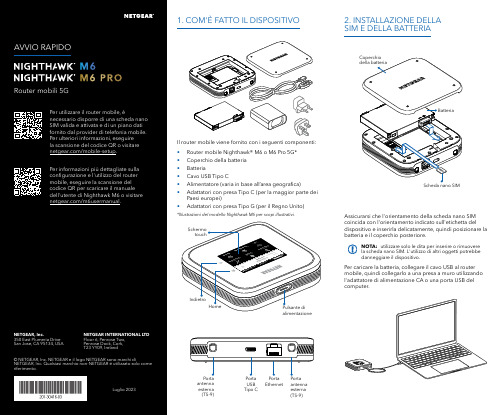
Per caricare la batteria, collegare il cavo USB al router mobile, quindi collegarlo a una presa a muro utilizzando l'adattatore di alimentazione CA o una porta USB del computer.Assicurarsi che l'orientamento della scheda nano SIM coincida con l'orientamento indicato sull'etichetta del dispositivo e inserirla delicatamente, quindi posizionare la batteria e il coperchio posteriore.NOTA: utilizzare solo le dita per inserire o rimuovere la scheda nano SIM. L'utilizzo di altri oggetti potrebbe danneggiare il dispositivo.1. COM'È FATTO IL DISPOSITIVO2. INSTALLAZIONE DELLA SIM E DELLA BATTERIAIl router mobile viene fornito con i seguenti componenti:• Router mobile Nighthawk® M6 o M6 Pro 5G*• Coperchio della batteria • Batteria• Cavo USB Tipo C• Alimentatore (varia in base all’area geografica)• Adattatori con presa Tipo C (per la maggior parte dei Paesi europei)•Adattatori con presa Tipo G (per il Regno Unito)*Illustrazioni del modello Nighthawk M6 per scopi illustrativi.antenna esterna (TS-9)antenna esterna (TS-9)USB Tipo CEthernetCONFORMITÀ NORMATIVA E NOTE LEGALIPer informazioni sulla conformità alle normative, compresala Dichiarazione di conformità UE, visitare il sito Web https:///it/about/regulatory/.Prima di collegare l'alimentazione, consultare il documento relativo alla conformità normativa.Può essere applicato solo ai dispositivi da 6 GHz: utilizzare il dispositivo solo in un ambiente al chiuso. L'utilizzo di dispositivi a 6 GHz è vietato su piattaforme petrolifere, automobili, treni, barche e aerei, tuttavia il suo utilizzo è consentito su aerei di grandi dimensioni quando volano sopra i 3000 metri di altezza. L'utilizzo di trasmettitori nella banda 5.925‑7.125 GHz è vietato per il controllo o le comunicazioni con sistemi aerei senza equipaggio.SUPPORTO E COMMUNITYDalla pagina del portale di amministrazione Web, fare clic sull'icona con i tre puntini nell'angolo in alto a destra per accedere ai file della guida e del supporto.Per ulteriori informazioni, visitare il sito netgear.it/support per accedere al manuale dell'utente completo e per scaricare gli aggiornamenti del firmware.È possibile trovare utili consigli anche nella Community NETGEAR, alla pagina /it.GESTIONE DELLE IMPOSTAZIONI TRAMITE L'APP NETGEAR MOBILEUtilizzare l'app NETGEAR Mobile per modificare il nome della rete Wi-Fi e la password. È possibile utilizzarla anche per riprodurre e condividere contenutimultimediali e accedere alle funzioni avanzate del router mobile.1. Accertarsi che il dispositivo mobile sia connesso a Internet.2. Eseguire la scansione del codice QR per scaricare l'appNETGEAR Mobile.Connessione con il nome e la password della rete Wi-Fi 1. Aprire il programma di gestione della rete Wi‑Fi deldispositivo.2. Individuare il nome della rete Wi‑Fi del router mobile(NTGR_XXXX) e stabilire una connessione.3. Only Connessione tramite EthernetPer prolungare la durata della batteria, l'opzione Ethernet è disattivata per impostazione predefinita. Per attivarla, toccare Power Manager (Risparmio energia) e passare a Performance Mode (Modalità performance).4. CONNESSIONE A INTERNETÈ possibile connettersi a Internet utilizzando il codice QR del router mobile da uno smartphone oppure selezionando manualmente il nome della rete Wi‑Fi del router e immettendo la password.Connessione tramite codice QR da uno smartphone 1. Toccare l'icona del codice QR sulla schermata inizialedello schermo LCD del router mobile.NOTA: quando è inattivo, lo schermo touch si oscura per risparmiare energia. Premere brevemente e rilasciare il pulsante di alimentazione per riattivare lo schermo.3. CONFIGURAZIONE DEL ROUTER MOBILETenere premuto il pulsante di accensione per due secondi, quindi seguire le istruzioni visualizzate sullo schermo per impostare un nome per la rete Wi‑Fi e una password univoci.La personalizzazione delle impostazioni Wi‑Fi consente di proteggere la rete Wi‑Fi del router mobile.Impostazioni APNIl router mobile legge i dati dalla scheda SIM e determina automaticamente le impostazioni APN (Access Point Name) corrette con i piani dati della maggior parte degli operatori. Tuttavia, se si utilizza un router mobile sbloccato con un operatore o un piano meno comune, potrebbe essere necessario immettere manualmente le impostazioni APN.Se viene visualizzata la schermata APN Setup Required (Configurazione APN richiesta), i dati APN dell’operatore non sono presenti nel nostro database ed è necessario inserirli manualmente. Immettere i valori fornitidall’operatore nei campi corrispondenti, quindi toccare Save (Salva) per completare la configurazione.NOTA: l’operatore determina le proprie informazioni APN e deve fornire le informazioni per il proprio piano dati. Si consiglia di contattare il proprio operatore per le impostazioni APN corrette e di utilizzare solo l’APN suggerito per il piano specifico.Schermata inizialeAl termine della configurazione, il router visualizza la schermata iniziale:Wi‑FiPotenza Carica Rete Codice QR connessione rapida Wi‑FiNome e Wi‑FiIcona del codice QR。
130nm_CMOS_Logic_process_flow_introduction
PR
PR
3.PR remove
4.Poly etch
5.SiON remove
NLH5AHPO550A
50:1 HF, 5sec+H3PO4 10mins
poly
poly
poly
10
Poly patterning ( 6T SRAM )
0.13/0.12um
Void cause by worse ILD HDP gap fill
PE SION for PID protection LRSIN for CT-ET stop layer
0.13/0.15um
HDP 4750A LRSIN300A SION150A
P+ N-Well P+ N+ P-Well N+
Gate ox.=60A+14.5A gate ox.2
Gate ox. 1+2~70A
Gate ox.=14.5A Gate ox. 2=14.5A
1.2 V NMOS P_WELL1 NLDD1
1.2 V PMOS N_WELL1 PLDD1
Remove the 1st Gate ox NLB85A
8
DUAL GATE
Gate ox. 1=58A 1750A poly
60Å thick gate oxide 14.5Å thin gate oxide
PR
Wet dip NLB85A
Gate ox. 1=60A
gate ox.1
P_WELL2/ NLDD2 3.3 V NMOS
马肯依玛士推出两款高解像度大字符喷码机

种 渗透 型材质上 喷印 .喷印环 境从O 到 4 ℃ 。喷 码 机 的 喷 印 速 度 最 高 可 达 O 1 2米/ 钟 , 可 选 配 喷 头 滑 块 组 件 . 8 分 以 优 化 喷 印 间距 控 制 和 喷 印 质 量 。
灵 活性 一尖 端 的 通 信 能 力 :包 括
彩 色 触 摸 屏 、 以太 网 、U B 网络 用 S 和
通 过 可 选 的 C L S E trr e 络 软 o O  ̄ nepi 网 s
E t pi 网络 软 件 ,通 过 远 程 数 据 库 n rr e e s
或 E P 统 集 中管 理 数 据 。 紧凑 、模 R 系
块 化 的设 计 可 单 机 或 集 成 工 作 。 硬 件
和 软 件 可 进 行 全 面 升 级 , 以满 足 不 断 变 化 的 商 务需 求 。 效 率 一先 进 、严 格 的 油 墨 管 理 系
们 圆 世博 之 梦 。 正 如 威 图 公 司郑 清 好
博 士 在 电 视采 访 中 所 说 : “ 助 这 些 帮
孩 子 .是 企 业
形 式 .带 领4 名上 海 孤儿 畅游 世博 园 。 0 让 这 些失 去 家庭 、失 去父 母 的孩 子 们 ,
的发 展 积 聚更 多 的力 量 。
件 ,通 过 远 程 数 据 库 或 E P 统 集 中 R 系
管 理 数 据 。 紧凑 、模 块 化 的设 计 可 单 机或集成工作。 效 率 一 进 的喷 码 机 设 计 可 确 保 先
统 ,带 有 大 容 量 的独 立 机 芯 ,专 门设
计 用 于 回收 经 过 净 化 的 油 墨 ,且 可 在
8月 2 0日 , 威 图 电 子 机 械 技 术
格林德

PeqSTAR96标准型快速PCR仪 PeqSTAR96标准型快速PCR仪 标准型快速PCR
技术指标: 技术指标: 6个HTR Peltier模块, PT1000传感器 运行中间可编程 温度范围:4—105℃ 控温准确性:±0.1℃ 升温速度:5℃/秒 降温速度:5℃/秒 升降速度、温度递增减、恒温时间皆可调 热盖压力、高度自动调节 热盖温度:70—120℃ 程序数:1000个 运行过程:电子锁防止热盖打开 断电保护功能 4个USB接口 样品量:96x0.2ml/48x0.5ml通用模块; 选配Motor热盖:384高通量模块,原位PCR模块、 HPL高压模块。 尺寸:29×31×36cm(W×D×H)
德国 格林德
Add: Bruehlstr. 92, 76227 Karlsruhe,Germany Tel: +49 721 6255821 Fax: +49 721 6255820 Email: contact@
格林德 北京
北京市朝阳区北四环东路108号千鹤家园乙5号楼1001室 Tel: +86 10 84832993 Fax: + 86 10 84832990 Email: contact@
格林德产品目录
化学分析仪器
色谱 I-Graph 气相色谱 GASMET气相色谱 质谱 IPI 在线质朴仪 X射线仪器 X-Ray 元素分析仪 定氮仪 德国elementar定氮仪 水分测定仪 WTW 水质分析仪 德国肖特卡式水分分析仪 生物实验室 PCR仪 PEQ lab PCR仪 凝胶成像系统 bio-step凝胶成像系统 intas凝胶成像系统 流式细胞仪 德国PARTEC流式细胞仪 电泳仪 德国科尔电泳仪 匀浆机 IKA匀浆机 德国ART匀浆机 德国海道夫匀浆机 生物反应器 德国HITEC ZANG生物反应器 瑞士INFORS生物反应器 德国DASGIA生物反应器 酶标仪 芬兰雷勃(Thermo Labsystems) MK3酶标仪 菌落计数仪 德国WTWBZG30菌落计数器 德国/schuett biotec菌落计数器 生化分析仪 荷兰威图vital 全自动生化分析仪 冻干机 zirbus VaCo 2-II 冻干机 德国christ冻干机 德国SRK冻干机 生命医疗 渗透压仪 德国Gonotec渗透压仪
IMS测厚仪

Measuring principle and Influencing factors
IMS Messsysteme GmbH Dieselstraße 55 D-42579 Heiligenhaus
© 2000 IMS GmbH
Phone: +49 (0) 2056 975 - 0 Fax: +49 (0) 02056 975 – 140 e-mail: info@ims-gmbh Internet: www.ims-gmbh.de
electronics Detector
Absorber
Thickness s
Material in the beam path is able to absorb radioactive radiation.
s = Density / Area weight Radiation source with shielding
Type of radiation Type of detector Time response Collimation
column in the beam path
Temperature of the material Alloying constituents Impurities in the beam path Water, scale, emulsion on the material Position of the material
F DF
S s Ds
= Area weight of an absorber
= Area weight change = Attenuation factor = Thickness of an absorber = Thickness change
迈格尔 CFL535G 高分辨率双通道时域反射仪说明书
CFL535GAdvanced Dual Channel TDR CFL535GAdvanced Dual Channel TDRDesCRipTionThe Megger® CFL535G is a state of the art, dual channel, high resolution, compact Time Domain Reflectometer with a color screen for locating faults on paired metallic cables.The CFL535G has a minimum resolution of 0.3 ft /0.1 m and a 60 kft/20 km maximum range depending on the velocity factor selected and the cable type.Five output impedances are available (25, 50, 75, 100, 125 ohms) and an auto impedance matching feature. The velocity factor can be set between 0.2 and 0.99 to meet any cable test requirements.FeATuRes AnD BeneFiTsThe CFL535G has a large, high resolution, color, WVGA display with easy set up features. Directional control buttons, together with soft keys, provide intuitive and easy operation for the user.An AUTO selection option ensures that the most effective parameters are selected depending on the range required, aiding rapid diagnosis of the TDR trace. The ability to manually override the auto function allows fine tuning to enable identification of hard to determine faults.Dual trace and dual cursor capabilities allow full flexibility, giving the operator full control and instant indication of distance between two points.A trace comparison feature also allows close examination between trace conditions. Extra high resolution together with a white-light backlight, user definable tones and color give the graphical display a vibrance, aiding the user in identifying key events on the trace. Trace storage100 internal trace memories provide for the storage andrecall of test results. The traces can be recalled to the display for analysis or compared with an active display to aid in fault location.Alternatively the stored results can be downloaded to a computer, via the USB port, using the TraceXpert software and USB lead provided.Fault identificationMegger’s own built-in Xpert mode allows for speedy identification of faults. One press of the Xpert key automatically adjusts the range and gain, and positions the cursor to the first major event on the cable. Press the Xpertkey again and the CFL535G will jump to the next detected disturbance.For those who wish to maintain manual control, manual operation allows full override access to refine the response for easy fault identification.TraceXpert pC softwareThe CFL535G comes complete with the Megger TraceXpert software which gives full control over downloading, reporting and uploading of saved trace results. Designed around a database and programmed for ease of use and simplicity, TraceXpert offers the ideal application for all your data processing requirements.■■Comprehensive Dual Channel capability with dual aspect display.■■AuTo set up mode for instant use.■■ultra fast pulse for near end fault identification.■■Xpert guidance to potential fault.■■ip54 rating offers real life working.■■Designed for use on all metallic pairedcables. 1981MoDeLsThe CFL535G is available in two models.CFL535G A fully featured high resolution TDR withbacklit color display and powered by Li-ionrechargeable battery batteries. This modelcomes complete with 2 pairs ofmini-clip Test Leads.TDR2000/3P The same as the CFL535G but with dualfused test leads replacing the mini-clip leads ADDiTionAL FeATuRes■■Backlit graphics color LCD (800x480)■■Adjustable display contrast■■Resolution to 0.1 m■■Trace Xpert guide to potential fault location■■100 trace on board memory■■USB connection to PC allowing upload and download of traces■■“TraceXpert” PC software analysis tool■■For use on Telecom TNV-3 circuit, or 150V CAT IV power circuits■■Power blocking filter built-in■■Environmental protection to IP54■■Selectable output impedance (25, 50, 75,100 and 125 Ω)■■2ns pulse for near end fault location■■AUTO option selecting gain and pulse for each range■■AUTO option matches output impedance to cable■■Display distance in metres or feet■■Li-ion rechargeable battery (12 hours typical life)speCiFiCATionExcept where otherwise stated, this specification applies at an ambient temperature of 68 ºF (20 ºC).GeneralRanges: Up to 20000m with a minimum resolution of 0.1m Accuracy: ±1% of range ± 1 pixel at 0.67VF[Note- The measurement accuracy is for the indicatedcursor position only and is conditional on the velocityfactor being correct.]Resolution: 1% of rangeInput Protection: This instrument complies with IEC61010-1 forconnection to live systems up to 150 V CAT IV.Fused leads must be used if the voltage between theterminals exceeds 300 V.Output pulse: Up to 20 volts peak to peak into open circuit. Pulsewidths determined by range and cableGain: Set for each range with user selectable steps (inManual operating mode)Velocity Factor: Variable from 0.2 to 0.99 in steps of 0.01TX Null: AutomaticPower Down: User programmable auto power off timer 1, 5, 10mins or offBatteries: Li-ion rechargeable battery with 12 hours typical life Safety: This instrument complies with IEC61010-1 forconnection to live systems up to 150 V CAT IV or300 V CAT III. Fused leads must be used if the voltagebetween the terminals exceeds 300 V. Compliant withEN60950-1, EN61010-3, UN38.3 and EN62133 EMC: Complies with Electromagnetic CompatibilitySpecifications (Light industrial) BS EN 61326-1, with aminimum performance of ‘B’ for all immunity tests Mechanical: The instrument is designed for use indoors oroutdoors and is rated to IP54.Case Dimensions: 11.4 in. x 7.5 in. x 2.2 in(290 mm x 190 mm x 55 mm)Weight: 3.8 lbs (1.7kg)Case material: ABSConnectors: Four 4mm-safety terminals and two F connectors.Other standard push on adapters will fit the CFL535G Test Leads: Bed-of-Nails lead set (CFL535G) or .5 meter fusedleads (TDR2000/3P)Display: 800 x 480 pixel WVGA color graphics LCD, viewablein external environments. User selectable colorschemesenvironmentalOperational Temperature: 5 ºF to 122 ºF (-15 ºC to 50 ºC) Charging Temperature: 32 ºF to 104 ºF (0 ºC to 40 ºC) Storage Temperature: -4 ºF to 158 ºF (-20 ºC to 70 ºC)CFL535GAdvanced Dual Channel TDRuKArchcliffe Road Dover CT17 9en england T +44 (0) 1304 502101F +44 (0) 1304 207342******************uniTeD sTATes2621 Van Buren Avenue norristown, pA 19403 usA T 1 866-254-0962 (usA only) T +1 610-676-8500 F +1 610-676-8625****************************(case sensitive email address )oTHeR TeCHniCAL sALes oFFiCes Dallas usA, College station usA,sydney AusTRALiA, Danderyd sWeDen, ontario CAnADA, Trappes FRAnCe,oberursel GeRMAnY, Aargau sWiTZeRLAnD, Dubai ueA, Mumbai inDiA, Durban souTH AFRiCA, Chonburi THAiLAnD, Malaga spAinCeRTiFiCATion isoRegistered to ISO 9001:2008 Cert. no. Q 09250Registered to ISO 14001-2004 Cert. no. EMS 61597CFL535G_Ds_usen_V05a Megger is a registered trademarkinformation contained herein subject to change without noticeCFL535GAdvanced Dual Channel TDR。
半导体组件 CSPEMI205G 3 通道耳机麦克风 EMI 滤波器及 ESD 保护器 用户手册说明
CSPEMI205G3-Channel Headset Microphone EMI Filter with ESD ProtectionProduct DescriptionThe CSPEMI205G is a low−pass filter array integrating three pi−style filters (C−R−C) that reduce EMI/RFI emissions while at the same time providing ESD protection. This part is custom−designed to interface with the headset port on a cellular telephone, and contains two different filter values. Each high quality filter provides more than 30 dB attenuation in the 800−2700 MHz range. These pi−style filters support bidirectional filtering, controlling EMI both to and from the microphone and speaker elements. They also support bipolar signals,enabling audio signals to pass through without distortion.In addition, the CSPEMI205G provides a very high level of protection for sensitive electronic components that may be subject to electrostatic discharge (ESD). The input pins safely dissipate ESD strikes of ±8 kV, the maximum requirement of the IEC 61000−4−2 international standard. Using the MIL−STD−883 (Method 3015) specification for Human Body Model (HBM) ESD, the device provides protection for contact discharges to greater than ±15 kV. The CSPEMI205G is particularly well−suited for portable electronics (e.g. cellular telephones, PDAs, notebook computers) because of its small package format and low weight. The CSPEMI205G is available in a space−saving, low−profile Chip Scale Package with RoHS compliant lead−free finishing.Features•Three Channels of EMI Filtering, Two for Earpiece Speakers and One for a Microphone•Pi−Style EMI Filters in a Capacitor−Resistor−Capacitor (C−R−C) Network•Chip Scale Package Features Extremely Low Parasitic Inductance for Optimum Filter Performance•Greater than 30 dB Relative Attenuation in the 800−2700 MHz Range•±8 kV ESD Protection on each Channel(IEC 61000−4−2 Level 4, Contact Discharge)•±15 kV ESD Protection on each Channel (HBM)•8−Bump, 1.41 x 1.430 mm Footprint Chip Scale Package (CSP)•These Devices are Pb−Free and are RoHS Compliant Applications•EMI Filtering and ESD Protection for Headset Microphone and Speaker•Cellular / Mobile Phones•Notebooks and Personal Computers•Handheld PCs / PDAs / Tablets•Wireless Handsets•Digital CamcordersMARKING DIAGRAMDevice Package Shipping†ORDERING INFORMATIONCSPEMI205G CSP−8(Pb−Free)3500/T ape & ReelWLCSP8CASE 567BE†For information on tape and reel specifications, including part orientation and tape sizes, please refer to our Tape and Reel Packaging Specification Brochure, BRD8011/D.AF= CSPEMI205GAF+ELECTRICAL SCHEMATICEarpiece 1Earpiece 1OutputEarpiece 2Earpiece 2OutputMicrophoneInputMicrophone OutputGND GNDTable 1. PIN DESCRIPTIONS8−bump CSP PackagePin Name DescriptionA1EAR1_IN Earpiece Input 1 (from audio circuitry)A3EAR2_IN Earpiece Input 2 (from audio circuitry)A5MIC_IN Microphone Input (from microphone)B2GND Device Ground B4GND Device GroundC1EAR1_OUT Earpiece Output 1 (to earpiece)C3EAR2_OUT Earpiece Output 2 (to earpiece)C5MIC_OUTMicrophone Output (to audio circuitry)PACKAGE / PINOUT DIAGRAMSO r i e n t a t i o n M a r k i n gCSPEMI205CSP PackageTop View(Bumps Down View)Bottom View (Pins Up View)i e n t a t i o n M a r k i n gSPECIFICATIONSTable 2. ABSOLUTE MAXIMUM RATINGSParameterRating Units Storage Temperature Range −65 to +150°C DC Power per Resistor 100mW DC Package Power Rating300mW Stresses exceeding Maximum Ratings may damage the device. Maximum Ratings are stress ratings only. Functional operation above the Recommended Operating Conditions is not implied. Extended exposure to stresses above the Recommended Operating Conditions may affect device reliability.Table 3. STANDARD OPERATING CONDITIONSParameterRating Units Operating Temperature Range−40 to +85°CTable 4. ELECTRICAL OPERATING CHARACTERISTICS (Note 1)Symbol ParameterConditionsMin Typ Max Units R 1Resistance 91011W R 2Resistance 546875W C 1Capacitance 80100120pF C 2Capacitance384757pF I LEAK Diode Leakage Current V IN = 5.0 V 1.0m A V SIGSignal Voltage Positive Clamp Negative ClampI LOAD = 10 mA5−157−1015−5VV ESDIn −system ESD Withstand Voltagea) Human Body Model, MIL −STD −883, Method 3015b) Contact Discharge per IEC 61000−4−2 Level 4(Notes 2 and 4)±15±8kVV CLClamping Voltage during ESD Discharge MIL −STD −883 (Method 3015), 8 kV Positive Transients Negative Transients (Notes 2, 3 and 4)+15−19Vf C1Cut −off frequency 1; (Note 5)R = 10 W , C = 100 pF 34MHz f C2Cut −off frequency 2; (Note 5)R = 68 W , C = 47 pF63MHz1.T A = 25°C unless otherwise specified.2.ESD applied to input and output pins with respect to GND, one at a time.3.Clamping voltage is measured at the opposite side of the EMI filter to the ESD pin. For example, if ESD is applied to Pin A1, then clamping voltage is measured at Pin C1.4.Unused pins are left open.5.Z SOURCE = 50 W , Z LOAD = 50 WPERFORMANCE INFORMATIONTypical Filter Performance (nominal conditions unless specified otherwise, 50 W Environment)Figure 1. Earpiece Circuit (A1−C1) EMI Filter PerformancePERFORMANCE INFORMATION (Cont’d)Typical Filter Performance (nominal conditions unless specified otherwise, 50 W Environment)Figure 2. Earpiece Circuit (A3−C3) EMI Filter PerformanceFigure 3. Microphone Circuit (A5−C5) EMI Filter PerformanceAPPLICATION INFORMATIONParameterValue Pad Size on PCB0.240 mm Pad Shape RoundPad Definition Non −Solder Mask defined padsSolder Mask Opening 0.290 mm Round Solder Stencil Thickness0.125 mm − 0.150 mm Solder Stencil Aperture Opening (laser cut, 5% tapered walls)0.300 mm Round Solder Flux Ratio 50/50 by volumeSolder Paste Type No CleanPad Protective FinishOSP (Entek Cu Plus 106A)Tolerance − Edge To Corner Ball ±50 m m Solder Ball Side Coplanarity±20 mm Maximum Dwell Time Above Liquidous60 seconds Maximum Soldering Temperature for Lead −free Devices using a Lead −free Solder Paste260°CNon −Solder Mask Defined Pad0.240 mm DIA.Solder Stencil Opening0.300 mm DIA.Solder Mask Opening0.290 mm DIA.Figure 4. Recommended Non −Solder Mask Defined Pad IllustrationFigure 5. Lead −free (SnAgCu) Solder Ball Reflow ProfileTime (minutes)T e m p e r a t u r e (5C )WLCSP8, 1.43x1.41CASE 567BE−01ISSUE ODATE 26 JUL 2010NOTES:1.DIMENSIONING AND TOLERANCING PERASME Y14.5M, 1994.2.CONTROLLING DIMENSION: MILLIMETERS.3.COPLANARITY APPLIES TO SPHERICALCROWNS OF SOLDER BALLS.2XDIMAMIN MAX0.56MILLIMETERSA1D 1.43 BSCEb0.290.35eD0.50 BSC0.650.210.271.41 BSCeE0.435 BSC0.25DIMENSIONS: MILLIMETERS*For additional information on our Pb−Free strategy and solderingdetails, please download the ON Semiconductor Soldering andMounting Techniques Reference Manual, SOLDERRM/D.SOLDERING FOOTPRINT*BOTTOM VIEWA20.40 REFRECOMMENDED MECHANICAL CASE OUTLINEPACKAGE DIMENSIONSON Semiconductor and are trademarks of Semiconductor Components Industries, LLC dba ON Semiconductor or its subsidiaries in the United States and/or other countries.ON Semiconductor reserves the right to make changes without further notice to any products herein. ON Semiconductor makes no warranty, representation or guarantee regarding the suitability of its products for any particular purpose, nor does ON Semiconductor assume any liability arising out of the application or use of any product or circuit, and specifically disclaims any and all liability, including without limitation special, consequential or incidental damages. ON Semiconductor does not convey any license under its patent rights nor thePUBLICATION ORDERING INFORMATIONTECHNICAL SUPPORTNorth American Technical Support:Voice Mail: 1 800−282−9855 Toll Free USA/Canada Phone: 011 421 33 790 2910LITERATURE FULFILLMENT :Email Requests to:*******************onsemi Website: Europe, Middle East and Africa Technical Support:Phone: 00421 33 790 2910For additional information, please contact your local Sales Representative。
赛米控丹佛斯电子 Board_93_GB_SKYPER_42_R 数据表

®Adaptor boardIGBT Driver CoreBoard 93 GB SKYPER 42 R Preliminary Data Features•Two output channels •Gold nickel finish •Failure managementTypical Applications*•Adaptor board for SKYPER 42 IGBT drivers in bridge circuits for industrial applications •PCB with gold plating •DC bus up to 1200VFootnotesIsolation test voltage with external high voltage diodeThe isolation test is not performed as a series test at SEMIKRONThe driver power can be expanded to 50µC with external boost capacitorsIsolation coordination in compliance with EN50178 PD2Operating temperature is real ambient temperature around the driver core Degree of protection: IP00This is an electrostatic discharge sensitive device (ESDS), international standard IEC 60747-1, Chapter IX* The specifications of our components may not be considered as an assurance of component characteristics. Components have to be tested for the respective application. Adjustments may be necessary. The use of SEMIKRON products in life support appliances and systems is subject to prior specification and written approval by SEMIKRON. We therefore strongly recommend prior consultation of our staff.Absolute Maximum Ratings SymbolConditionsValuesUnitV s Supply voltage primary 16V Iout PEAK Output peak current 30A Iout AVmax Output average current 150mA f max Max. switching frequency100kHz V CECollector emitter voltage sense across the IGBT1700V V isol IO Isolation test voltage input - output (AC, rms, 2s)4000V V isolPD Partial discharge extinction voltage, rms, Q PD ≤ 10pC1500V V isol12Isolation test voltage output 1 - output 2 (AC, rms, 2s)1500V R Gon min Minimum rating for external R Gon 0.8ΩR Goff min Minimum rating for external R Goff 0.8ΩT op Operating temperature -40...85°C T stgStorage temperature-40 (85)°CCharacteristics SymbolConditionsmin.typ.max.UnitV s Supply voltage primary side 14.41515.6V V i Input signal voltage on / off 15 / 0V V IT+Input treshold voltage HIGH 12.3V V IT-Input threshold voltage (LOW) 4.6V V G(on)Turn on output voltage 15V V G(off)Turn off output voltage-8V t d(on)IO Input-output turn-on propagation time 1.1µs t d(off)IOInput-output turn-on propagation time1.1µsAdaptor Board 93 SKYPER® 42 RTechnical ExplanationsRevision 04------------------------------------------------------------------------------------------------------------------------------------------------------------------------------------------ This Technical Explanation is valid for the following parts:Related documents:Prepared by: Johannes Krapp------------------------------------------------------------------------------------------------------------------------------------------------------------------------------------------ ContentApplication and Handling Instructions (2)Further application support (2)General Description (2)Dimensions (3)PIN Array (3)Setting Dynamic Short Circuit Protection (4)Collector Series Resistance (4)Adaptation Gate Resistors (5)Boost Capacitors (6)Environmental conditions (6)Mounting Notes (6)Please note:All values in this technical explanation are typical values. Typical values are the average values expected in large quantities and are provided for information purposes only. These values can and do vary in different applications. All operating parameters should be validated by user’s technical experts for each application.Application and Handling Instructions▪Please provide for static discharge protection during handling. As long as the hybrid driver is not completely assembled, the input terminals have to be short-circuited. Persons working with devices have to wear a grounded bracelet. Any synthetic floor coverings must not be statically chargeable. Even during transportation the input terminals have to be short-circuited using, for example, conductive rubber. Worktables have to be grounded. The same safety requirements apply to MOSFET- and IGBT-modules.▪Any parasitic inductances within the DC-link have to be minimised. Over-voltages may be absorbed by C- or RCD-snubber networks between main terminals for PLUS and MINUS of the power module.▪When first operating a newly developed circuit, SEMIKRON recommends to apply low collector voltage and load current in the beginning and to increase these values gradually, observing the turn-off behaviour of the free-wheeling diode and the turn-off voltage spikes generated across the IGBT. An oscillographic control will be necessary. Additionally, the case temperature of the module has to be monitored. When the circuit works correctly under rated operation conditions, short-circuit testing may be done, starting again with low collector voltage.▪It is important to feed any errors back to the control circuit and to switch off the device immediately in failure events.Repeated turn-on of the IGBT into a short circuit with a high frequency may destroy the device.▪The inputs of the hybrid driver are sensitive to over-voltage. Voltages higher than V S +0,3V or below -0,3V may destroy these inputs. Therefore, control signal over-voltages exceeding the above values have to be avoided.▪The connecting leads between hybrid driver and the power module should be as short as possible (max. 20cm), the driver leads should be twisted.Further application supportLatest information is available at . For design support please read the SEMIKRON Application Manual Power Modules available at .General DescriptionThe Board 93 GB SKYPER® 42 is an adaptor board for the IGBT module SKiM® 93 (spring contact). The board is paralleling three channels so the SKiM module can be used in half bridge configuration. The board can be customized allowing adaptation and optimization to the used IGBT module.The switching characteristic of the IGBT can be influenced through user settings, e.g. changing turn-on and turn-off speed by variation of R Gon and R Goff. Furthermore, it is possible to adjust the monitoring level and blanking time for the DSCP (see Technical Explanations SKYPER® 42 R).Please note:This technical explanation is based on the Technical Explanations for SKYPER®42 R. Please read the Technical Explanations SKYPER® 42 R before using the Adaptor Board.Dimensions116 PIN ArraySetting Dynamic Short Circuit ProtectionThe Vce formula for the Vce monitoring is described in the technical explanation of SKYPER 42 R. Collector Series ResistanceDesignation Shape SettingR105 MiniMELF (SMD) R VCE*Factory setting: not equippedTOPR205 MiniMELF (SMD) R VCE *Factory setting: not equippedBOTAdaptation Gate ResistorsBoost CapacitorsEnvironmental conditionsPlease refer to the technical explanation of SKYPER 42 R for the environmental conditions.Mounting NotesDISCLAIMERSEMIKRON reserves the right to make changes withoutfurnished in this document is believed to be accurate and reliable. However, no representation or warranty is given and no liability is assumed with respect to the accuracy or use of such information. SEMIKRON does not assume any liability arising out of the application or use of any product or circuit described herein. Furthermore,。
万事达传感器:MIP系列重度、媒介隔离压力传感器,1bar至12bar 15psi至175psi说明

MIP SERIESHeavy Duty, Media-Isolated Pressure Transducers 1 bar to 12 bar | 15 psi to 175 psiDESCRIPTIONThe MIP Series offers a heavy duty,media-isolated pressure transducer in a compact, stainless steel construction for use with a wide range of media including aggressive fluids and water. The MIP Series provides a cost-competitive solution for wide-ranging potential applications in tough environments.VALUE TO CUSTOMERS•Total Error Band (TEB) ±0.75 %FSS to ±1.0 %FSS (Full Scale Span)from -40°C to 125°C: Provides true measurement performance over the compensated temperature range;small error promotes system uptime and efficiency (see Figure 4).•EMC performance: Operates reliably in the presence of electromagnetic fields, such as wireless signals, RF communication, and electrical devices.• Hermetically welded design supports almost any media without the use of an internal seal. The sensors are designed to be used in harsh environments that see aggressive media. PORTFOLIOHoneywell offers a variety of heavy duty pressuretransducers for potential use in industrial and transportation applications. To view the entire product portfolio, click here.DIFFERENTIATION•Diagnostics: Beneficial in applications where the sensor functionality and the need to know internal or external failure modes is critical.•Great customer value: Multiple configuration possibilities provideflexibility of use in the application with no up front NRE or tooling charges.•Durable: Provides the toughenvironmental capabilities needed,including long-term stability, insulation resistance and dielectric strength,external freeze-thaw resistance and EMC performance.32353264Issue BFEATURES•Rugged, stainless steel construction •Ratiometric output: 0.5 Vdc to 4.5 Vdc •Operating temperature: -40°C to 125°C •Total Error Band ±0.75 %FSS to ±1.0 %FSS (-40°C to 125°C)•An industry leader in accuracy : ±0.15%FSS BFSL•Long term stability: ±0.25 %FSS •Radiated immunity: 100 V/m•Drinking water approval: NSF /ANSI/CAN 61•CE, RoHS, REACH compliant •Mis-wiring protection•Over voltage protection ±40 VdcCertified to NSF/ANSI/CAN 611range. Includes all errors due to offset, full scale span, pressure non-linearity, pressure hysteresis, pressure non-repeatability, thermal effect on offset, thermal effect on span, and thermal hysteresis (see Figure 4).2TEB: ±1.5 % FSS above 100°C [212°F] for pressure ratings less than 4 bar [58 psi].3Accuracy: The maximum deviation in output from a Best Fit Straight Line (BFSL) fitted to the output measured over the pressure range at 25°C [77°F]. Includes all errors due to pressure non-linearity, pressure hysteresis, and pressure non-repeatability.4Startup time:The time needed to receive valid output after power up.FIGURE 1. NOMENCLATURE AND ORDER GUIDE1For example, MIPAN1XX010BSAAX defines an MIP Series Heavy Duty, Media Isolated Pressure Transducer, Metri-Pack 150, standard (UL V-0) electrical connector type, 1/4-18 NPT pressure port type, 10 bar pressure range, sealed gage pressure reference, ratiometric: 5 Vs, 10% to 90% Vs output transfer functionCAUTIONPRODUCT DAMAGE DUE TO MISUSE•Ensure torque specifications are determined for the specific application. Values provided are for reference only. (Mating materials and thread sealants can result in significantly different torque values from one application to the next.)•Use appropriate tools (such as an open ended wrench or deep well socket) to install transducers.•Ensure that the proper mating electrical connector with a seal is used to connect the transducer. Improper or damaged seals can compromise ingress protection, leading to short circuits.•Ensure that filters are used upstream of the transducers to keep media flow free of large particulates and condensed moisture.MIP Series transducers are dead-end devices. Particulate accumulation may clog the port or damage the diaphragm.•Ensure that the transducer is mounted in a vertical position with the process connection (pressure port) downward to avoid particulate deposits.•Ensure that the media does not create a residue when dried. Build-up of residue inside the transducer may affect transducer output.•Ensure that the transducer housing is properly grounded.Failure to comply with these instructions may result in product damage.10Pressure (psi Absolute)O u t p u t (V)4FIGURE 3. ABSOLUTE VS SEALED GAGE Example shown is for 100 psi.FIGURE 2. RATIOMETRIC OUTPUT TRANSFER FUNCTION The transfer function shown here is applicable to a ratiometric output ranging between 10% V supply at null pressure to 90% V supply at full scale pressure.Total Error Bandmin.O u t p u t (% V s u p p l y )0.8 x V supplyOutput (V) =x (Pressure applied - P min.) + 0.10 x V supply Ideal max.P max.- P min.O u t p u t (V d c )Total Error Band (TEB) is a single specification that includes the major sources of sensor error. TEB should not be confused with accuracy, which is actually a component of TEB. TEB is the maximum error that the sensor could experience.Honeywell uses the TEB specification in its datasheet because it is the most comprehensive measurement of a sensor’s true accuracy. Honeywell also provides the accuracy specification in order to provide a common comparison with competitors’ literature that does not use the TEB specification.Many competitors do not use TEB—they simply specify the accuracy of their device. Their accuracy specification, however, may exclude certain parameters. On their datasheet, the errors are FIGURE 4. TEB COMPONENTS FOR THE MIP SERIES is returned to the operating pressure range. Exposure to higher pressures may cause permanent damage to the product.2Burst Pressure: The maximum pressure which may be applied without causing escape of pressure media. The product should not be expected to function after exposure to the burst pressure.HEAVY DUTY, MEDIA-ISOLATED PRESSURE TRANSDUCERS, MIP SERIESFIGURE 5. MOUNTING DIMENSIONS (FOR REFERENCE ONLY. MM/[IN])F1: 7/16-20 UNF 1/4 inch 45° Flare Female Schrader (SAE J512)Seal: 45° coneMating geometry: SAE J512Weight:G1: G1/4 A-G (ISO 1179-3)Seal: O-ring (included) and retaining ring ISO 1179-3-G1/4(not included)Seal:Weight:Weight:Product MarkingRatiometric Voltage OutputPin A = GroundPin B = V+Pin C = Vout(Productmarking)16-Digit product listingPin BPin C[0.87](Productmarking)MIPXXXXXXXXXXXXXH YYMMDD XXXXX16-Digit product listing5-Digit serial number6-Digit dateHoneywelllogoCE MarkCEPin BFOR MORE INFORMATION Honeywell Advanced Sensing Technologies services its customers through a worldwide network of sales offices and distributors. For application assistance, current specifications, pricing or the nearest Authorized Distributor, visit our website or call: USA/Canada +1 302 613 4491 Latin America +1 305 805 8188 Europe +44 1344 238258 Japan +81 (0) 3-6730-7152 Singapore +65 6355 2828 Greater China +86 4006396841 HoneywellAdvanced Sensing Technologies 830 East Arapaho Road Richardson, TX 75081 WARRANTY/REMEDYHoneywell warrants goods of itsmanufacture as being free of defectivematerials and faulty workmanshipduring the applicable warranty period.Honeywell’s standard product warrantyapplies unless agreed to otherwise byHoneywell in writing; please refer toyour order acknowledgment or consultyour local sales office for specificwarranty details. If warranted goodsare returned to Honeywell during theperiod of coverage, Honeywell willrepair or replace, at its option, withoutcharge those items that Honeywell,in its sole discretion, finds defective.The foregoing is buyer’s sole remedyand is in lieu of all other warranties,expressed or implied, including thoseof merchantability and fitness for aparticular purpose. In no event shallHoneywell be liable for consequential,special, or indirect damages.While Honeywell may provideapplication assistance personally,through our literature and theHoneywell web site, it is buyer’ssole responsibility to determinethe suitability of the product in theapplication.Specifications may change withoutnotice. The information we supply isbelieved to be accurate and reliableas of this writing. However, Honeywellassumes no responsibility for its use.m WARNINGPERSONAL INJURYDO NOT USE these products as safetyor emergency stop devices or in anyother application where failure of theproduct could result in personal injury.Failure to comply with theseinstructions could result in death orserious injury.ADDITIONAL MATERIALSThe following associated literature isavailable on our website:•Product range guide•Application-specific and technicalinformation•CAD Models32353264-B-EN | B | 03/21。
罗森格勒高频技术有限公司SMP全闸插接口产品数据表说明书

All dimensions are in mm; tolerances according to ISO 2768 m-HInterfaceAccording to MIL-STD-348DocumentsAssembly instruction 19 GMaterial and platingConnector parts Material PlatingCenter contact Kovar per ASTM F 15-78 Gold, min. 0.8 µm, over nickel Outer contact Kovar per ASTM F 15-78 Gold, min. 0.8 µm, over nickel Dielectric Corning 7070 glassFull Detent.14/6.2D i e s e s D o k u m e n t i s t u r h e b e r r e c h t l i c h g e s c h üt z t ● T h i s d o c u m e n t i s p r o t e c t e d b y c o p y r i g h t ● R o s e n b e r g e r H o c h f r e q u e n z t e c h n i k G m b H & C o . K Gf(GHz)Electrical dataImpedance 50 ΩFrequency DC to 26.5 GHzReturn loss ≥ 23 dB, DC to 18 GHz Insertion loss≤ 0.05 x dB, DC to 18 GHz Insulation resistance≥ 5 G Ω Center contact resistance ≤ 6.0 m Ω Outer contact resistance ≤ 2.0 m Ω Test voltage 500 V rms Working voltage 335 V rms Contact Current 1.2A DC max.Mechanical dataMating cycles≥ 100 Center contact captivation ≥ 7 N Engagement force - full detent68 N max. Disengagement force - full detent 22 N min.Environmental dataTemperature range -65°C to +155°CThermal shock MIL-STD-202, Method 107, Condition B Vibration MIL-STD-202, Method 204, Condition B ShockMIL-STD-202, Method 213, Condition A Moisture resistance MIL-STD-202, Method 106 Soldering temperature 250°C max. Leakage rate ≤ 10-8 mbar x l/s Pressure 2 N/mm 2 max. RoHS compliantToolingN/ASuitable cablesN/AWeightWeight0.09 g/pceDraftDate Approved DateRev. Engineering change numberName Date Inge Mühlauer 15.02.05L. Bombik11.08.23g0023-0004S. Schier11.08.23While the information has been carefully compiled to the best of our knowledge, nothing is intended as representation or warranty on our part and no statement herein shall be construed as recommendation to infringe existing patents. In the effort to improve our products, we reserve the right to make changes judged to be necessary.For the installation of the electrotechnical equipment, particular electrotechnical expertise is required.。
瑞士万通手持快速拉曼分析仪--陈树坤

瑞士万通手持快速拉曼分析仪Mira – Metrohm Instant Raman AnalyzersWith the mobile Mira spectrometers you can rapidly extract a great deal of chemical information of a wide variety of unspecified samples. Within seconds, the handheld analyzers offer you reliable and easy interpretable results, be it for material verification or counterfeit detection.∙Reproducible results with averaging Orbital- Raster-Scan (ORS) mode for the most complex samples∙Maximum flexibility – «open library» principle ensures reliable outcomes∙Reduced to the max – light, compact, handy2.923.0020Mira M-1 Advanced PackageThe M etrohm I nstant R aman A nalyzers (Mira) are handheld,high-performance Raman spectrometers for rapid, nondestructive analysis ofchemical and pharmaceutical samples, be they liquid or solid. Barely largerthan a smartphone, the Mira M-1 spectrometers are the only handheld Raman spectrometers available with Orbital-Raster-Scan (ORS) technology. With theAdvanced Package, powders, granulates or liquids can be analyzed directly intheir containers with the Point-and-Shoot Adapters. Alternatively, thesamples can also be presented in small vials.2.923.0010Mira M-1 Basic PackageThe M etrohm I nstant R aman A nalyzers (Mira) are handheld, high-performance Raman spectrometers for rapid, nondestructive analysis of chemical and pharmaceutical samples, be they liquid or solid. Barely larger than a smartphone, the Mira spectrometers are the only handheld Raman analyzers available with Orbital-Raster-Scan (ORS)technology. With the Basic Package, with integrated sample holder, the samples can be presented directly in small vials for ready use in the Mira M-1 spectrometer (laser protection class 1).6.6071.622Raman spectral library of flavors and scentsRaman spectra of flavors, scents, and other substances that are used for manufacturing cosmetics and fragrances (> 1,030 spectra).6.6071.621Raman spectral library of biochemicalsRaman spectra of biochemicals, including vitamins, resins, starches, glycerins, fatty acids, sugars, carbohydrates, proteins, and peptides (> 1,900 spectra).6.6071.620Raman spectral library of food additivesRaman spectra of food additives, including FDA-controlled substances. Additionally, spectra of indirect food additives and substances that come into contact with foodstuffs, such as packaging materials and associated processing chemicals (>1,070 spectra).6.6071.619Raman spectral library of inorganic materialsRaman spectra of inorganic materials (> 960 spectra; extracted from the 6.6071.617 spectral library).6.6071.618Raman spectral library of mineralsRaman spectra of minerals (> 450 spectra; extracted from the 6.6071.617 spectral library).6.6071.617Raman spectral library of minerals and inorganic materialsRaman spectra of minerals and inorganic materials (> 1,410 spectra). This library is notincluded in the complete Raman spectral library (6.6071.601). The library is comprised of > 450 Raman spectra of minerals and > 960 Raman spectra of inorganic materials.6.6071.616Raman spectral library of substances with a high production volume Raman spectra of substances with a high production volume, as listed in the "HPV Challenge Program Chemical List" (> 690 spectra).6.6071.615Raman spectral library of sulfur and phosphorus compoundsRaman spectra of sulfur and phosphorus compounds (> 970 spectra).6.6071.614Raman spectral library for the dye industryRaman spectra of selected dyes, colorants, pigments, and indicators (> 300spectra).6.6071.613Raman spectral library of agricultural chemicalsRaman spectra of pesticides, insecticides, herbicides, fungicides, algicides, and similar agricultural chemicals (> 460 spectra).6.6071.612Raman spectral library for forensic analysisRaman spectra of substances that are relevant to forensic analysis (> 740 spectra).6.6071.611Raman spectral library for hazardous substances (EPA, USCG, NIOSH) Raman spectra of selected hazardous substances that are listed in the "EPA Cameo Database for Chemical Emergencies and Responders", "USCG Chris Hazardous Chemicals Database" and "NIOSH Guide to Chemical Hazards Databases", as well as chemicals that are regulated by the "Toxic Substances Control Act" (> 3,030spectra).6.6071.610Raman spectral library of hazardous substances (EPA, USCG)Raman spectra of selected hazardous substances that are listed in the "EPA Cameo Database for Chemical Emergencies and Responders" and the "USCG CHRIS Hazardous Chemicals Database (> 1,360 spectra).6.6071.609Raman spectral library for the semiconductor industryRaman spectra of chemical substances that are used in the semiconductor industry (> 370 spectra).6.6071.608Raman spectral library of (halogenated) hydrocarbonsRaman spectra of hydrocarbons and halogenated hydrocarbons (> 560 spectra).6.6071.607Raman spectral library of esters, lactones, and anhydridesRaman spectra of esters, lactones, and anhydrides (> 2,930 spectra).6.6071.606Raman spectral library of alcoholic and phenolic compoundsRaman spectra of alcoholic and phenolic compounds (> 890 spectra).6.6071.605Raman spectral library of aldehydes and ketonesRaman spectra of aliphatic and aromatic aldehydes and ketones (> 1,070 spectra).6.6071.604Raman spectral library for the polymer industryRaman spectra of polymers, polymer additives, plastics, plasticizers, and packaging materials (> 920 spectra).6.6071.603Raman spectral library of solventsRaman spectra of solvents (> 460 spectra).6.6071.602Raman spectral library for the pharmaceutical industryRaman spectra of active substances and auxiliary materials that are relevant to the pharmaceutical industry and medical research (> 1,170 spectra).6.6071.601Complete collection of Raman spectra (> 8,690 spectra)Metrohm provides an extensive collection of Raman spectra for Mira spectrometers. The complete Raman spectral library, with more than 8,690 spectra, is comprised of 21 sublibraries and is thus eminently suited for the identification of unknown Raman spectra and for the characterization of a very wide variety of materials.6.6071.000Mira Cal softwareThe user-friendly Mira Cal software is used primarily for saving data, datatransfer and the activation/deactivation of spectral libraries. In addition, MiraCal is ideal for using the "open library" principle. This means that libraries canbe created that are tailored to the solving of a very specific problem.。
世界各大测井集团仪器编码表

世界各大测井集团仪器编码表BAKER ATLAS WIRELINE (贝克休斯公司-电缆测井)3DEX 3D Induction Logging Service (三维感应)AC BHC Acoustilog (井眼补偿声波)CAL Caliper (井径)CBIL Circumferential Borehole Imaging Log (井周成像测井)CDL Compensated Density Log (补偿密度测井)CN Compensated Neutron Log (补偿中子测井)DAC Digital Array Acoustilog (数字阵列声波测井)DAL Digital Acoustilog (数字声波测井)DEL2 Dielectric Log - 200 Mhz (介电测井-200兆赫)DEL4 Dielectric Log - 47 Mhz (介电测井-47兆赫)DIFL Dual Induction Focused Log (双感应聚聚测井)DIP High Resolution 4-Arm Diplog (高分辨率4臂地层倾角)DLL Dual Laterolog (双侧向测井)DPIL Dual Phase Induction Log (双相位感应测井)EI Earth Imager (地层成像仪)FMT Formation Multi-Tester (地层多功能测试器)GR Gamma Ray (伽马仪)HDIL_BA High-Definition Induction Log (高分辨率感应测井)HDIP Hexagonol Diplog (六臂倾角测井)HDLL High-Definition Lateral Log (高分辨率侧向测井)ICAL Imaging Caliper (井径成像仪)IEL Induction Electrolog (感应-电测井)ISSB Isolation Sub - Spontaneous Potential (自然电位隔离短节)MAC Multipole Array Acoustilog (多极子阵列声波测井)MAC2 Multipole Array Acoustilog (多极子阵列声波测井2)MFC Multi-Finger Caliper (多臂井径仪)ML Minilog (微电极测井仪)MLL Micro Laterolog (微侧向)MREX Magnetic Resonance Explorer Imaging Log (核磁共振探测成像测井) MRIL Magnetic Resonance Imaging Log (核磁共振成像测井)MSL Micro Spherical Laterolog (微球侧向测井)ORIT Directional Survey (井斜方位测井仪)PDK PDK-100PROX Proximity Log (邻近侧向测井仪)RCI Reservoir Characterization Instrument (储层特征描述仪)RCOR Rotary Sidewall Coring Tool (钻进式井壁取心器)RPM Reservoir Performance Monitor (油藏动态监测仪)SBT Segmented Bond Tool (分区水泥胶结测井仪)SL Spectralog (能谱仪)SP Spontaneous Potential (自然电位)STAR Simultaneous Acoustic and Resistivity Imager (声波电阻联合成像仪) SWC Sidewall Coregun (井壁取心器)SYST Surface System (地面系统)TBRT Thin-Bed Resistivity (薄层电阻率)TTRM Temperature/Tension/Mud Resistivity Sub (温度张力泥浆电阻率短节)VS Velocity Survey (速度测量仪)VSP Vertical Seismic Profile (垂直地震剖面)WTS ECLIPS WTS Downhole Common Remote (ECLIPS 井下通用遥传)XMAC Cross-Multipole Array Acoustilog (交叉多极子阵列声波)XMAC-E XMAC Elite (Next generation XMAC) (特种交叉多极子声波) ZDL Compensated Z-Densilog (补偿Z-密度)BAKER INTEQ(贝克休斯INTEQ公司.-随钻测井)AP Annular Pressure (环空压力仪)APX Accoustic Porosity Explorer (声波孔隙度探测仪)CCN Caliper Corrected Neutron (井径校正中子)DIR Directional (定向仪)DPRT Deep Propagation Resistivity (深传播电阻率)FMT Formation Multi-Tester (地层多功能测试器)GR Gamma Ray (伽马仪)MPR Multiple Propogation Resistivity (多传播电阻率)MRT Magnetic Resonance (核磁共振)ORD Compensated Bulk Density(补偿体积密度)RIT Resistivity Imaging (电阻率成像仪)VSS Vibration and Stick Slip (振动蠕动仪)COMPUTALOG 公司AZD Azimuthal Density (方位密度)BCS Borehole Compensated Sonic (井眼补偿声波)CAL Caliper (井径)CDT Compensated Density (补偿密度)CNT Compensated Neutron (补偿中子)DAR Digital Acoustic Tool (数字声波)DLL Dual Laterolog (双侧向测井)DTD Tension Compression (张/压力计)FED Four Electrode Dipmeter (四电极倾角)GR Gamma Ray (伽马仪)GRN Gamma Ray Neutron (伽马中子)HADR High Temperature Azimuthal Gamma Ray (高温方位伽马) HBC High Resolution Borehole Sonic 高分辨率井眼声波)HMI High Resolution Micro Imager (高分辨率微成像)IEL Induction Electric Log (感应测井)MAN Multi Array Neutron (阵列中子)MDA Monopole Dipole Acoustic (单偶极子声波)MEL Micro Electric Log (微电极测井)MFR Multi Frequency Resistivity (多频电阻率测井)MRT400 Micro Resistivity Tool (微电阻率测井仪)MSC Multi Sensor Caliper (多探头井径)MSFL Micro Spherically Focused Log (微球型聚焦测井)NMRT Nuclear Magnetic Resonance Tool (核磁共振测井)NTT Single Detector Neutron (单探头中子)PND Pulsed Neutron Decay (脉冲中子衰变)(中子寿命)RSCT Rotary Sidewall Coring Tool (钻进式井壁取心器)SAGR Spectral Azimuthal Gamma Ray (方位能谱伽马)SED Six Electrode Dipmeter (六电极倾角)SFT Selective Formation Tester (选择性地层测试器)SGR Spectral Gamma Ray (能谱伽马)SP Spontaneous Potential (自然电位)SPeD Spectral Pe Density (能谱Pe密度)STI Simultaneous Triple Induction (联合三感应)TEN Tension (张力计)TNP Thermal Neutron Porosity (热中子孔隙度)HALLIBURTON(哈里伯顿公司.电缆测井)BCS Borehole Compensated Sonic (井眼补偿声波)BHPT Borehole Properties Tool (井眼特性仪器)CAST Circumferential Acoustic Scanning(环形声波扫描仪)CDL Compensated Density Log (补偿密度测井)CSNG Compensated Spectral Natural Gamma Ray (补偿能谱中子伽马) DIL Dual Induction Log (双感应测井)DLLT Dual Laterolog (双侧向测井)DSN Dual Spaced Neutron (双源距中子仪)EMI Electrical Micro Imaging (微电成像)FIAC Four Independent Arm Caliper (四独立臂井径)FWS Full Wave Sonic (全波列声波)GR Gamma Ray (伽马仪)HDIL_HAL Hostile Dual Induction (无敌双感应)HDTD Hostile Downhole Tension (无敌井下张力仪)HFDT High Frequency Dielectric (高频介电测井仪)HRI High Resolution Induction (includes HRAI) (高分辨率感应)HSN Hostile Short Normal (无敌短电位测井仪)LSS Laterolog 3 (三侧向) Long Spaced Sonic (长源距声波)MACT Multi-Arm Caliper Tool (多臂井径仪)MICLOG Microlog (微电极测井仪)MRIL Magnetic Resonance Imaging Log (核磁共振成像测井)MSFL Micro-Spherically Focused Log (微球型聚焦测井仪)NGRT Gamma Ray Tool (伽马仪)RDT Reservoir Description Tool (油藏描述测井仪)RSCT Rotary Sidewall Coring (钻进井臂取心器)SDL Spectral Density Log (能谱密度侧井)SED Six Arm Dipmeter (六臂倾角)SFT Sequential Formation Tester (连续地层测试器)SGR Spectral Gamma Ray (能谱伽马)SP Spontaneous Potential (自然电位)Thermal Multigate Decay-Lithology (热中子多选通衰变岩性测井仪) TMD-LWSD WaveSonic Dipole (偶极子声波)XYC XY Caliper Log (XY井径仪)HALLIBURTON SPERRY SUN(哈里伯顿-随钻测井)ACAL AcoustiCaliper (声波井径)AGR Azimuthal Gamma Ray (方位伽马)ALD Azimuthal Litho Density (方位岩性密度)ASLD Azimuthal Stabilized Litho Density (方位稳定岩性密度)BAT Bi-Modal Acoustic Tool (Bi模声波仪)CNP Compensated Neutron Porosity (补偿中子孔隙度)CTNCompensatedThermalNeu;DDSDrillingDynamicsSenso;DGRDualGammaRay(双伽马仪);DIRDirectional(定向仪);EWP4EWR-Phase4(电磁波电阻率-相4;EWR-M5EWR-M5Resistivity(;EWR-P4EWR-Phase4Resisiti;EWR-P4DEWR-PhCTN Compensated Thermal Neutron (补偿热中子)DDS Drilling Dynamics Sensor (钻进动态探测仪)DGR Dual Gamma Ray (双伽马仪)DIR Directional (定向仪)EWP4 EWR - Phase 4 (电磁波电阻率-相4)EWR-M5 EWR-M5 Resistivity (电磁波电阻率-M5)EWR-P4 EWR-Phase 4 Resisitivity (电磁波电阻率-P4)EWR-P4D EWR-Phase 4D Resistivity (电磁波电阻率-P4D)EWRS Electromagnetic Wave Resistivity (Shielded) (屏蔽电磁波电阻率测井仪) GeoTap GM GeoTap Formation Tester (GeoTa地层测试仪) Gamma Module (伽马探测单元)GPGR Geo-Pilot Azimuthal Gamma Ray (Geo-Pilot方位伽马)IVSS Insert Vibration Severity Sensor (嵌入式振动硬度探测仪)MRIL-WD Magnetic Resonance Image Logging (随钻核磁共振成像仪) NGP Natural Gamma Probe (自然伽马探测仪)NUCP Smoothed Neutron Porosity(平滑中子孔隙度)PCG Pressure Case GammaPPFG Pore Pressure/Fracture Gradient (孔隙压力与破裂梯度)PWD Pressure While Drilling (随钻压力探测仪)SFD Simultaneous Formation Density (同行地层密度)SLD Stabilized Litho Density (稳定岩性密度)SSEWR-P4 SuperSlim EWR-Phase 4 (超小井眼电磁波电阻率-P4)SVSS Sonde Vibration Severty Sensor (探头式振动强度探测仪)PATHFINDER LOGGING(导航测井公司)AWR Array Wave Resistivity/Gamma Ray(波列电阻率与伽马)CLSSM Compensated Long Spaced Sonic MultiLink (多连接补偿长源距声波) CWRGM Compensated Wave Resistivity Gamma MultiLink(多连接补偿波列电阻率伽马)DFT Dynamic Formation Tester (动态地层电阻率测试器)DIR Directional (定向仪)DNSCM Density Neutron Standoff Caliper MultiLink (多连接密度中子支撑井径)DPM Dynamic Pressure Module (动态压力单元)GAM Gamma Ray Sonde (伽马探头)GyroHDS1 Gyro High-Speed Directional Survey (旋转高速定向仪) HDS1LHDS1R High-Speed Directional Survey(高速定向仪1L) High-Speed Directional Survey Retrievable (高速定向仪1R) HDSM High-Speed Directional Survey MultiLink (多连接高速定向仪) PWD Pressure While Drilling (随钻压力探测仪)PZIG At-Bit Inclination and Gamma Ray (钻头倾斜于伽马)QPM Survivor Dynamic Pressure Module (动压探测单元)SAWR Slim Array Wave Resistivity/Gamma Ray (小井眼波列电阻率与伽马) SCLSS Slim Compensated Long Spaced Sonic (小井眼补偿长源距声波) SCWR Slim Compensated Wave Resistivity (小井眼补偿波列电阻率)SDNSC Slim Density Neutron Standoff Caliper (小井眼密度中子支撑井径) PRECISION ENERGY (精准能源)AZD Azimuthal Density (方位密度)BAP Bore/Annular Pressure (井眼环空压力)BCS Borehole Compensated Sonic (井眼补偿声波)CALI General Caliper (通用井径仪)CNS Compensated Neutron Service (补偿中子测井)CNT Compensated Neutron Tool (补偿中子仪)DLL Dual Laterolog (双侧向测井)ESM Environmental Severity Measurement (环境硬度测试仪)FCAL Single Axis Caliper (单轴井径仪)GR Flow Rate Tester (泵量测试仪) Gamma Ray (伽马仪)HAGR High Temperature Azimuthal Gamma Ray (高温方位伽马)HBC High Resolution Borehole Sonic (高分辨率井眼声波)HMI High Resolution Micro Imager (高分辨率微成像)IDS Integrated Directional Sonde (综合定向仪)MCG Compact Gamma (嵌入式伽马)MDA Monopole Dipole Array (单偶极子阵列声波)MDN Compact Dual Neutron Sonde (嵌入式双源距中子仪)MFR Multi-Frequency Resistivity (多频电阻率)MFT Compact Repeat Formation Pressure Tester (嵌入式反复式地层压力测试器)MGS Auxiliary Gamma Sub (辅助伽马短节)MPD Compact PhotoDensity Sonde (嵌入式光密度仪)MRT Micro Resistivity Tool (微电阻率测井仪)MSFL Micro Spherically Focused Log (微球型聚焦测井)NMRT Nuclear Magnetic Resonance Tool (核磁共振测井)RSCT Rotary Sidewall Coring Tool (钻进式井壁取心器)SED Six Electrode Dipmeter (六电极倾角)SFT Selective Formation Tester (选择性地层测试器)SGR Spectral Gamma Ray (能谱伽马)SGS-C Spectral Gamma Sonde (能谱伽马探头)SPeD Spectral Pe Density (能谱Pe密度)STI Simultaneous Triple Induction (联合三感应)SWC Sidewall Coring Gun (井壁取心器)TNP Thermal Neutron Porosity (热中子孔隙度)UGR Universal Gamma Ray (多功能伽马仪)VSP Vertical Seismic Profile (垂直地震剖面)PROTECHNICS公司SpectraS SpectraScan - spectral gamma ray (能谱伽马)REEVES WIRELINE 公司MAI Compact Array Induction (嵌入式阵列感应)MBN Compact Borehole Navigator (嵌入式井眼定向仪)MDL_R Compact Dual Laterolog Sonde (嵌入式双侧向)MDN Compact Dual Neutron (嵌入式双源距中子)MFE High Resolution Shallow Focused Electric (高分辨率浅聚焦电法仪) MFT Compact Repeat Formation Pressure Tester (嵌入式重复地层压力测试器) MGS Auxilary Gamma Sub (辅助伽马短节)MML Compact Microlog (嵌入式微电极)MMR Compact Microlaterolog (嵌入式微侧向)MPD Compact PhotoDensity (嵌入式光密度仪)MSS Compact Sonic Sonde (嵌入式声波)MTC Compact Two Arm Caliper (嵌入式两臂井径仪)MCG Compact Gamma (嵌入式伽马)SCHLUMBERGER(斯伦贝谢)AACT Aluminium Activation Clay Tool (铝活化粘土仪)ACT Geochemical Logging Tool (地球化学测井仪)ADN Azimuthal Density Neutron (方位密度中子)AGS Aluminium Gamma Ray Spectroscopy Sonde (铝伽马能谱仪) AIT Array Induction Imager (阵列感应)ALAT Azimuthal Laterolog (方位侧向)AMS Auxiliary Measurement Sonde (辅助测量仪)APS Accelerator Porosity Sonde (加速器型孔隙度探测仪)APWD Annular Pressure While Drilling (随钻环空压力)ARC Array Compensated Resistivity (阵列补偿电阻率)BHTV Borehole Televiewer (井下电视)BSP Bridle Spontaneous Potential (加长电缆自然电位)CALI Generalized Caliper (通用井径仪)CBTT Combinable Borehole Televiewer Tool (组合式井下电视)CDN Compensated Density Neutron (补偿密度中子)CDR Compensated Dual Resistivity (补偿双电阻率)CHFR Cased Hole Formation Resistivity (套管井地层电阻率) CHFT Cased Hole Dynamics Tester (套管井动态测试仪)CMR Combinable Magnetic Resonance (组合式核磁共振) CNL Compensated Neutron Log (补偿中子测井)CNT Compensated Neutron Tool (补偿中子仪)CNTS Slim Compensated Neutron Tool (小井眼补偿中子仪)CST Core Sample Taker; Chronological Sample Taker (井壁取心器) DGR Dual Gamma Ray (双伽马仪)DIT Directional (定向仪) Dual Induction (双感应)DLT Dual Laterolog (双侧向测井)DPT Deep Propagation Tool (深探测电磁波传播测井仪) DSI Dipole Shear Sonic Imager (双极子横波成像仪)DSLT Digitizing Sonic Logging (数字声波)DSST Dipole Shear Sonic Imager (双极子横波成像仪)DST Dual Laterolog with SRT (双侧向微球型聚焦仪)DWST Digital Waterform Sonic (数字波列)ECO Ecoscope (电子耦合仪)ECS Elemental Capture Spectroscopy Sonde (自然俘获能谱仪) EDTC Telemetry Cartridge (遥测短节)EMS Environmental Measurement Sonde (环测仪)EPT Electromagnetic Propagation (ADEPT) (电磁波传播仪) ES Electrical Survey Tool (电法测井仪)FBST Fullbore Formation Micro Imager (全井眼地层微成像仪) FGT Formation Gamma Gamma (地层伽马)FMI Fullbore Formation Micro Imager (全井眼地层微成像仪) FMS Formation Micro Scanner (地层微扫描仪)FPWD Formation Pressure While Drilling (随钻地层压力)GFAFormationTesterGammaR;GNTGammaNeutronTool(伽马中子;GPITGeneralPurposeInclin;GRGammaRay(伽马仪);GRAGeochemicalReservoirA;GRSTGammaRaySpectrometry;GRTGammaRayTool(伽马仪);GSTGeo-SteeringTooGFA Formation Tester Gamma Ray Detector (地层测试伽马探测器) GFT Formation Tester Gamma Ray (地层测试伽马探测器)GNT Gamma Neutron Tool (伽马中子)GPIT General Purpose Inclinometry Tool (通用测斜仪)GR Gamma Ray (伽马仪)GRA Geochemical Reservoir Analyzer (地球化学储层分析器)GRST Gamma Ray Spectrometry Tool (伽马能谱仪)GRT Gamma Ray Tool (伽马仪)GST Geo-Steering Tool (地质导向仪)HALS High Resolution Azimuthal Laterlog Sonde (高分辨率方位侧向)HAPS HPHT Accelator Porosity Sonde (aka XAPS) (HPHT加速度型孔隙度) HDT High Resolution Dipmeter (高分辨率倾角)HGNS HILT Gamma Ray Neutron Sonde (高集成伽马中子仪)HILT High Integrated Logging Tool 9(高集成测井仪)HIT Hostile Array Induction Tool (aka XAIT) (无敌阵列感应)HLDS Hostile Litho-Density Sonde (无敌岩性密度)HLDT Hostile Environment Litho-Density(无敌自然岩性密度)HNGS Hostile Gamma Ray Neutron Sonde (无敌伽马中子仪)HNGT Hostile Natural Gamma Ray Spectrometry (无敌中子伽马能谱) HRCC High Resolution Control Cartridge (高分辨率控制短节)HRDD HILT High Resolution Density Device (高集成高分辨率密度仪)HRGD HILT High Resolution Resitivity Gamma Ray Density Device (高集成高分辨率电阻率伽马密度仪)HRLT High-Resolution Laterolog Array Tool (高分辨率阵列侧向)HRMS High Resolution Measurement Sonde (高分辨率测试仪)HSGT Hostile Environment Gamma Ray (无敌自然伽马仪)HSLT HPHT Digial Sonic Logging Tool (aka XSLT) (高温高压数字声波) IMPA IMPulse Array Compensated Resistivity (脉冲阵列补偿电阻率) IPL Integrated Porosity Lithology (集成孔隙度岩性仪)IRT Induction Resistivity Tool (感应电阻率测井仪)LWD Sonic (随钻声波) ISONICLDS Litho Density Sonde (岩性密度测井仪)LDT Litho Density (岩性密度)LSS Long Spaced Sonic (长源距声波)MCFL Micro-Cylindrically Focused Log (微柱型聚焦测井)MDLT Medium Dual Laterolog (介质双侧向仪)MDT Modular Formation Dynamics Tester (模块式地层动态测试器) MLT Microlog (微电极测井仪)MRPS Modular Formation Dynamics Tester Single-Probe (模块式地层动态测试器单探头)MRSC Modular Formation Dynamics Tester Sample Chamber (模块式地层动态测试器取样筒)MRWD Magnetic Resonanace While Drilling (随钻核磁共振)MSCT Mechanical Sidewall Coring Tool (机械式井壁取心器)MSIP Modular Sonic Imaging Platform (模块式声波成像平台)MWD Measurement While Drilling (多功能随钻测量)NGS Natural Gamma Ray Sonde (自然伽马)NGT Natural Gamma Ray Spectrometry (自然伽马能谱)NMT Nuclear Magnetism (核磁共振仪)NPLC Nuclear Porosity Lithology (核孔隙度岩性仪)NPLT Nuclear Porosity Lithology (核孔隙度岩性仪)OBDT Oil Base Mud Dipmeter (油基泥浆地层倾角)OBMI Oil Base Micro Imager (油基泥浆微成像仪)OBMT Oil Base Mud Formation Imager (油基泥浆地层成像仪)PERI Periscope (潜望镜)PGT Compensated Density (补偿密度)PMIT PS Platform Multifinger Imaging Tool (PS平台多指成像仪) PNT Sidewall Neutron Tool (井壁中子仪)QAIT Slim Hostile Array Inducation Tool (小井眼阵列感应)QCNT Slim Hot Compensated Neutron Tool (小井眼高温补偿中子) QLDT Slim Xtreme Litho-Density Tool (小井眼特种岩性密度)QSCS Slimhole Power Caliper Sonde (小井眼电动井径仪)QSLT Slim Xtreme Sonic Logging Tool (小井眼特种声波)QTGC SlimXtreme Telemetry and Gamma Ray (小井眼特种遥测伽马)RAB Resisitivity at Bit;Azimuthal Laterolog - Gamma Ray (aka GVR) (钻头位电阻率方位侧向伽马)RFT Repeat Formation Tester (重复式地层测试器)RST Reservoir Saturation Tool (储层饱和度测井)SAIT Slimhole Array Induction (小井眼阵列感应)SDT Sonic Digital (数字声波)SGT Scintillation Gamma Ray (闪烁伽马)SHARP Slim Hole Retrievable MWD Tool (SHDT Stratigraphic High Resolution Dipmeter Tool (地层高分辨率倾角) SLDT Slimhole Litho-Density (小井眼岩性密度)SLIM1 Slim Hole Retrievable MWD Tool (小井眼可起出随钻测井仪) SLT Borehole Compensated Sonic Logging Tool (井眼补偿声波)SMRT Slim Micro Resistivity Tool (小井眼微电阻率测井仪)SNPD Sidewall Neutron Tool (井壁中子仪)SONVIS SonicVISION (声波成像)SP Spontaneous Potential (自然电位)SPE SP Extender (自然电位增强仪)SPULSE Slim Pulse MWD Directional (小井眼脉冲随钻定向仪)SRT Microspherically Focused Resistivity (微球型聚焦电阻率测井仪) SSLT Slim Array Sonic Logging Tool (小井眼阵列声波)STETHO Stethoscope (金属探伤仪)SVWD Seismic Vision While Drilling (随钻地震成像)TDT Thermal Decay Time (热中子衰变时间)TELE Telescope (望远镜)TLD Three-Detector Lithology Density (三维岩性密度)UBI Ultrasonic Borehole Imager (超声井壁成像)USIT Ultrasonic Imager Tool (超声成像仪)VIPER VIPER Slimhole Coiled Tubing MWD Tool (VIPER小井眼随钻挠性管) VISP Vertical Incident Seismic Profile (垂直入射地震剖面)VSI Borehole Seismic Acquisition Tool (井眼地震剖面采集仪)VSP Vertical Seismic Profile (垂直地震剖面)WAVSP Walk Away Vertical Seismic Profile (偏离垂直地震剖面) XPT Pressure Express (快速压力探测仪)WEATHERFORD(威德福公司)AZD Azimuthal Density (方位密度)BAP Bore/Annular Pressure (井眼环空压力)BCS Borehole Compensated Sonic (井眼补偿声波)CAL Caliper (井径)CALI Generalized Caliper (通用井径仪)CDT Compensated Density (补偿密度)CNS Compensated Neutron Service (补偿中子测井)CNT Compensated Neutron Tool (补偿中子仪)DAR Digital Acoustic Tool (数字声波)DIR Directional Survey (井斜方位测井仪)DLL Dual Laterolog Log (双侧向测井仪)DTD Tension Compression (张/压力计)ESM Environmental Severity Measurement (环境硬度测试仪)FCAL Single Axis Caliper (单轴井径仪)FED Four Electrode Dipmeter (四电极倾角)GR Flow Rate Tool (泵量测试仪) Gamma Ray (伽马仪)GRN Gamma Ray Neutron (伽马中子)HAGR High Temperature Azimuthal Gamma Ray (高温方位伽马)HBC High Resolution Borehole Compensated Sonic Log (高分辨率井眼补偿声波)HMI High Resolution Micro Imager (高分辨率微成像)IEL Integrated Directional Sonde (综合定向仪) Induction Electrolog (感应-电测井)MAI Compact Array Induction (嵌入式阵列感应)MAN Multi Array Neutron (阵列中子)MBN Compact Borehole Navigation (嵌入式井眼定位仪)MCG Compact Gamma (嵌入式伽马)MDA Monopole Dipole Acoustic (单偶极子声波)MDL_R Compact Dual Laterolog Sonde (嵌入式双侧向)MDN Compact Dual Neutron (嵌入式双源距中子)MEL Micro Electric Log (微电极测井)MFE High Resolution Shallow Focused Electric (高分辨率浅聚焦电法仪) MFR Multi Frequency Resistivity (多频电阻率测井)MFT Compact Repeat Formation Pressure Tester (嵌入式反复式地层压力测试器)MGS Auxilary Gamma Sub (辅助伽马短节)MMR Compact Microlaterolog (嵌入式微侧向)MPD Compact PhotoDensity (嵌入式光密度仪)MRT400 Micro Resistivity Tool (微电阻率测井仪)MRT-P Micro Resistivity Tool (微电阻率测井仪)MSFL Micro-Spherically Focused Log (微球型聚焦测井仪)MSS Compact Sonic Sonde (嵌入式声波)MTC Compact Two Arm Caliper (嵌入式两臂井径仪)NMRT Nuclear Magnetic Resonance Tool (核磁共振测井)NTT Single Detector Neutron (单探头中子)RSCT Rotary Sidewall Coring (HRSCT) (钻进式井壁取心器)SAGRSpectralAzimuthalGam;SFTSequentialFormationTe;SGS-CSpectralGammaSonde(;SPEDSpectralPeDensity(能谱;SST;STIShockWaveSonicTool(冲击;TENTension(张力计);TNPThermalNeutronPorosit;SAGR Spectral Azimuthal Gamma Ray (方位能谱伽马)SED Six Arm Dipmeter Survey (六臂倾角)SFT Sequential Formation Tester (连续地层测试器) SGR Spectral Gamma Ray (能谱伽马)SGS-C Spectral Gamma Sonde (能谱伽马探头) SP Spontaneous Potential (自然电位)SPED Spectral Pe Density (能谱Pe密度)STI Shock Wave Sonic Tool (冲击波声波仪) Simultaneous Triple Induction (联合三感应)SWC Sidewall Coregun (井壁取心器)TEN Tension (张力计)TNP Thermal Neutron Porosity (热中子孔隙度) UGR Universal Gamma Ray (多功能伽马仪) VSP Vertical Seismic Profile (垂直地震剖面)。
Mini-MELF(SOD-80)
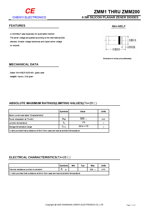
Forward Characteristics
Admissible power dissipation versus ambient temperature
Copyright @ 2000 SHANGHAI CHENYI ELECTRONICS CO.,LTD
Page 4 of 8
CE
CHENYI ELECTRONICS
<7
<50
1
<10
<15
<70
<20
<70
<20
<90
<26
<110
<30
<110
<40
<170
<50
<170
<55
<55
<220 <80
<90
<500
<110
<600
<125 <135
<700
<150
<200 <1000
<250
<300 <1500 0.25
<450 <2000
<450 <600
<5000
114…127.
130
1
124…141
150
138…156
160
153…171
180
168…191
200
188…212
Dynamic resistance 1)
rZjt and rZjk at IZK
mA
<8
<50
<85 <600