BMT-2512B中文资料
大毅2512合金低温漂采样电阻RLM25系列选型手册

pull 300 mm/min standard: 0.1 ~ 0.7 N
12. Storage Conditions:
Temperature: 5℃~35℃,Humidity:40%~75%
13. Shelf Life:
2 years from manufacturing date.
TA-I TECHNOLOGY CO., LTD
www.jepsun.com
Document No
TRLM-250S149C 2015/11/24 4/6
Lead-Free Current Sensing Resistors RLM Series ( Halogen-Free )
Issued date Page
7. Number of Package: 4000 Pieces / package
2. Type Designation:
RLM Item 25 Series No. 25:2512 (6432) F Resistance tolerance F:±1% G:±2% J:±5% E Packaging C Power rating C=1W D=1.5W E=2W R010 Resistance
Iron Solder:350±10℃ , 3+1/-0 sec
℃ , 5 sec
15. ECN
Engineering Change Notice: The customer will be informed with ECN if there is significant modification on the characteristics and materials described in Approval Sheet.
2512中文资料

For more information, contact Pulse Consumer Division Applications Engineering via e-mail at: consumer@.
46
G003.U (2/07)
元器件交易网
14"- 90° color TV Set-top Box 14"÷21" - 90° 17"÷21" - 90° 110° Color TV 25"÷29" 110° Color TV 28"÷34" 110° Color TV 14"-15" CTV 90° 25"-29" CTV 110° LCD TV 26" LCD TV 26"-32"
Series (Part Number)
2182 2414 2444 2464 2074 2074.5 2084 2094 2344 2354
2502 2502.5 2512 2522 2532 2542 2552 2562 2102 2722 2732
2742
2432 2182.5 2252 2262 2262.5 2362 2361 2362.3 2362.5 2362.7 2452 2452.7 2472
Applications
This transformer is mainly intended to be used as a Resonant Switch-Mode Transformer for low-end 22” LCD TV sets with mains insulation. The most suitable circuit topology for this transformer is a half-bridge, quasi-resonant converter using Phillips ZVS controller TEA1610. The common range of operation for this switch-mode transformer is from 50-200 kHz.
肖特基二极管参数表
肖特基二极管参数表【原创版】目录一、肖特基二极管概述二、肖特基二极管参数表详解三、肖特基二极管的应用场景四、结论正文一、肖特基二极管概述肖特基二极管,又称为肖特基势垒二极管,是一种金属与半导体接触的整流器件。
它具有很高的工作效率和较低的正向电压降。
肖特基二极管广泛应用于整流、限幅、开关和稳压等电路中。
二、肖特基二极管参数表详解肖特基二极管参数表主要包括以下几个方面:1.最大重复峰值反向电压(VRRM):表示二极管能够承受的最大重复峰值反向电压。
例如,MBR10200CT 肖特基二极管的 VRRM 为 200V。
2.最大直流闭锁电压(VDC):表示二极管在最大直流电压下仍能保持导通状态的电压值。
例如,MBR10200CT 肖特基二极管的 VDC 为 200V。
3.最大正向平均整流电流(I(AV)):表示二极管在最大正向电压下能够通过的平均整流电流。
例如,MBR10200CT 肖特基二极管的 I(AV) 为10.0A。
4.最大瞬时正向电压(VF):表示二极管在最大正向电流下对应的正向电压。
例如,MBR10200CT 肖特基二极管的 VF 为 0.92V。
5.额定直流阻断电压下的最大直流反向电流(IR):表示二极管在最大直流阻断电压下能够承受的最大直流反向电流。
例如,MBR10200CT 肖特基二极管的 IR 分别为 0.1mA(TA25)和 20.0mA(TA125)。
6.工作温度和存储温度范围(TJ,TSTG):表示二极管能够正常工作的温度范围和存储温度范围。
例如,MBR10200CT 肖特基二极管的 TJ,TSTG 为 -65to 175。
三、肖特基二极管的应用场景肖特基二极管广泛应用于以下场景:1.整流电路:将交流电转换为直流电,例如在电源电路中。
2.限幅电路:限制信号波形的幅值,例如在音频处理电路中。
3.开关电路:实现开关控制功能,例如在场效应管开关电路中。
4.稳压电路:稳定输出电压,例如在稳压电源电路中。
TH2512 TH2512A 说明书

±%RDC+ 字
< 4V
DC
分辩率 温度系数
1 μΩ
100ppm
10 μΩ
100 μΩ
50ppm
1
10
mΩ mΩ
100
1
mΩ Ω
50ppm
10 100
Ω
Ω
误差
注: TH2512 1μΩ到 2MΩ TH2512A 10μΩ到 200 kΩ
显示:最大 19999 字,LED 触发:连续/单次 测试:4 端(2 根电压检测端,2 根电流驱动端)。 量程:自动/手动 分选:分选 ON/OFF 测量速度:快速 10 次/秒,慢速 2.5 次/秒 GPIB(IEEE488):所有前面板的功能都可以远控。
11. 量程:量程自动选择,AUTO(LED 亮)时,仪器自动选择量程。
12. 速度:测试速度选择键,共有 2 个测试速度,快速(FAST)及慢速(SLOW),每按一下换 另外一种测试速度。
四.面板文字说明
1.mΩ,Ω,kΩ,MΩ:测试值显示单位,分别为毫欧姆、欧姆、千欧姆、兆欧姆。 2.REMOTE:远控接口 IEEE488 与电脑连接控制指示信号,当亮时,表示只接受电脑控制。 3.UNKNOWN:被测端口待测电阻输入端子。 4.HIGH,PASS,LOW:分选结果指示,为上超差(HIGH),合格(PASS)或下超差(LOW)指
常州同惠电子设备公司
TH2512/TH2512A 面板
1. 清零:清零功能按键,按了此键会将面板显示之电阻值扣除归零(OFFSET 值),以后之测 试值显示为扣除此 OFFSET 值,在清零 ON 时(LED 亮)显示将会有+/-号。
2. > :当在测量状态时,功能为量程向上一档选择键;当在设置状态时,功能为向右移一 数位。
贴片肖特基二极管封装

贴片肖特基二极管封装通过型号识别封装外形:MBR10100:TO-220AC,单芯片,两引脚,MBR10100CT:TO-220AB,双芯片,三引脚,型号后缀带CT MBRB10100CT:TO-263(D 2 PAK)、贴片。
型号前面第四个字母B,代表TO-263,国际通用命名。
双芯片,三引脚,型号后缀带CT MBRD1045CT:TO-252(DPAK)、贴片。
MBRD与MBRB都是贴片,D:TO-252,B:TO-263。
MBR3045PT:TO-3P,型号后缀“PT”代表TO-3P封装,原MOTOROLA(今ON)叫做SOT-93 SD1045:D表示TO-251 常见贴片封装的肖特基型号:BAT54、BAT54A、BAT54C、BAT54S:SOT-23,0.3AMBR0520L、MBR0540:SOD-123,0.5ASS12、SS14:DO-214AC(SMA),1ASL12、SL14:DO-214AC(SMA),1ASK22:SK24:DO-214AA(SMB),2ASK32:SK34:DO-214AB(SMC),3AMBRD320、MBRD360:TO-252,3AMBRD620CT、MBRD660CT:TO-252,6AMBRB10100CT:TO-263(D 2PAK),10AMBRB4045CT:TO-263(D2PAK),40A常见插件封装的肖特基型号:MBR150、MBR160:DO-41,轴向,1A1N5817(1A/20V)、1N5819(1A/40V),轴向,DO-41;1N5820(3A/20V)、1N5822(3A/40V),轴向,DO-201ADMBR340、MBR3100:(3A/40V),DO-201AD轴向,MBR735、MBR745:TO-220AC(两脚),7AMBRB735、MBRB745:贴片、TO-263(D 2 PAK),7AMBR1045、MBR1060:TO-220AC(两脚),10AMBR1045CT、MBR10100CT:TO-220AB(三脚半塑封),10AMBRF1045CT、MBRF10100CT:TO-220F,(三脚全塑封),10A(第4位字母F为全塑封)MBR1535CT、MBR1545CT:TO-220AB(三脚),15AMBR2045CT、MBR20200CT:TO-220AB(三脚),20AMBR2535CT、MBR2545CT:TO-220AB(三脚),25AMBR3045CT、MBR3060CT:TO-220AB(三脚),30AMBR3045PT、MBR3060PT:TO-247(TO-3P),30AMBR4045PT、MBR4060PT:TO-247(TO-3P),40AMBR6045PT、MBR6060PT:TO-247(TO-3P),60A器件型号主要参数常规封装形式MBR1045CT,10A,45V,TO-220AB、TO-220F全塑封;MBR1060CT,10A,60V,TO-220AB、TO-220F全塑封;MBR10100CT,10A,100V,TO-220AB、TO-220F全塑封;MBR10150CT,10A,150V,TO-220AB、TO-220F全塑封;MBR10200CT,10A,200V,TO-220AB、TO-220F全塑封;MBR2045CT,20A,45V,TO-220AB、TO-220F全塑封;MBR2060CT,20A,60V,TO-220AB、TO-220F全塑封;MBR20100CT,20A,100V,TO-220AB、TO-220F全塑封;MBR20150CT,20A,150V,TO-220AB、TO-220F全塑封;MBR20200CT,20A,200V,TO-220AB、TO-220F全塑封;MBR3045CT,30A,45V,TO-220AB、TO-220F全塑封;MBR3060CT,30A,60V,TO-220AB、TO-220F全塑封;MBR30100CT,30A,100V,TO-220AB、TO-220F全塑封;MBR30150CT,30A,150V,TO-220AB、TO-220F全塑封;MBR30200CT,30A,200V,TO-220AB、TO-220F全塑封;MBR3045PT,30A,45V,TO-247、TO-3P;MBR3060PT,30A,60V,TO-247、TO-3P;MBR30100PT,30A,100V,TO-247、TO-3P;MBR30150PT,30A,150V,TO-247、TO-3P;MBR30200PT,30A,200V,TO-247、TO-3P;MBR4045PT,40A,45V,TO-247、TO-3P;MBR4060PT,40A,60V,TO-247、TO-3P;MBR40100PT,40A,100V,TO-247、TO-3P;MBR40150PT,40A,150V,TO-247、TO-3P;MBR40200PT,40A,200V,TO-247、TO-3P;MBR6045PT,60A,45V,TO-247、TO-3P;MBR6060PT,60A,60V,TO-247、TO-3P;MBR60100PT,60A,100V,TO-247、TO-3P;。
肖特基二极管参数表
肖特基二极管参数表(原创版)目录1.肖特基二极管的概念与特点2.肖特基二极管的参数表及其含义3.肖特基二极管的应用领域4.肖特基二极管的发展前景正文一、肖特基二极管的概念与特点肖特基二极管,又称为肖特基势垒二极管,是一种金属与半导体接触的电子器件。
它具有很高的工作速度、较低的正向电压和较大的反向电流。
肖特基二极管的这些特性使其在电子设备中具有广泛的应用。
二、肖特基二极管的参数表及其含义肖特基二极管的参数表包括以下几个主要参数:1.最大重复峰值反向电压(VRRM):表示肖特基二极管能够承受的最大重复峰值反向电压。
例如,MBR10200CT 肖特基二极管的 VRRM 为 200V。
2.最大直流闭锁电压(VDC):表示肖特基二极管在最大直流电压下能够正常工作的电压值。
例如,MBR10200CT 肖特基二极管的 VDC 为 200V。
3.最大正向平均整流电流(I(AV)):表示肖特基二极管在最大正向电压下能够通过的平均整流电流。
例如,MBR10200CT 肖特基二极管的 I(AV) 为 10.0A。
4.最大瞬时正向电压(VF):表示肖特基二极管在最大正向电流下能够承受的瞬时正向电压。
例如,MBR10200CT 肖特基二极管的 VF 为 0.92V。
5.额定直流阻断电压下的最大直流反向电流(IR):表示肖特基二极管在最大直流阻断电压下能够承受的最大直流反向电流。
例如,MBR10200CT 肖特基二极管的 IR 在最大直流阻断电压 TA25 下为0.1mA,在最大直流阻断电压 TA125 下为 20.0mA。
6.工作温度和存储温度范围(TJ,TSTG):表示肖特基二极管能够正常工作的温度范围。
例如,MBR10200CT 肖特基二极管的工作温度和存储温度范围为 -65to 175。
三、肖特基二极管的应用领域肖特基二极管广泛应用于各种电子设备中,如电源开关、稳压器、充电器、电视机、收音机等。
其高速开关特性使得肖特基二极管在高频应用领域具有优势。
010126 BMT2512H12-07LF(C)

Product No.
010126
Issue No.
BS/TET01.632C
Issue Date
11/11/19
Approval:
1.Characteristics 2.Dimension 3.Reliability Test 4.Packing 5.Notice 6.History change record
C
C
B
B
C B AA Rev.
11/11/19 10/09/02 01/06/20
Date
6
常琦 陶红仲 胡海青 Drawn
5
change SPL&Pin's length&
Package
Date:
RohS
Drawn by:
Checked by:
Note
Approved by:
11/11/19 常琦 魏奉玲 张秀琴
5
change SPL&Pin's length&
Package
Date:
RohS
Drawn by:
Checked by:
Note
Approved by:
11/11/19 常琦 魏奉玲 张秀琴
wu@
4
3
BMT2512H12-07 LF
Transducer
"XX . X" means "year.month"
E.g : Jun, 2009 is "09.F "
D
D
2-Ø0.8±0.05
Unit:mm Tolerance: 0.3
C
C
大毅2512贴片厚膜电阻RM02-25选型手册

J-±5% G-±2% F-±1% D-±0.5% B-±0.1%
T-Paper Tape E-Embossed Tape B-Bulk Cassette +N: Lead-Free Special L : 06 – 2mm pitch paper Tape
3 digits, e.g.,: (E-24) 103 = 10kΩ 0 = 0Ω 4 digits, e.g., : (E-96) 1540 = 154Ω 43R2 = 43.2Ω
2. Operating Temp(℃): : -55℃ 〜 +155℃
( RM02 -55℃ 〜 +125℃ )
Note : Except for the above standardized products, we also provide the customized products.
深圳捷比信--高品质精密元件供应商
深圳捷比信--高品质精密元件供应商
www.jepsun.com
Document No. TRM-XX0S002B Revise Date page number 2013/11/08 2/12
Thick Film Chip Resistors ( Lead-Free for RM series standard ) Halogen-Free
5. Ratings & Characteristics :
Type Power Rating at 70℃ Max. Rating Working Voltage Voltage Max. OverLoad Voltage T.C.R (PPM/℃ ) ±200 +600 -200 ±100 ±200 50V 100V +500 -200 ±400 ±100 RM06 1/10W Refer 5.2 50V 100V ±200 ±400 150V 300V ±100 ±200 ±400 200V 400V ±100 ±200 ±400 200V 400V ±100 ±200 ±400 200V 400V ±100 ±200 ±400 200V 400V ±100 ±200 ±400
CJT长江连接器A2512系列

1.80±0.05
1.80±0.05
0.60±0.05
SEC:B-B
Ordering information & Specifications:
Part NO
Wire Range Insulation O.D.
A2512F-TP
AWG#22-#28 1.70mm(max)
A2512F-GP
AWG#22-#28 1.70mm(max)
A2512-T
2.50mm Pitch Crimp Terminal
Reference Informations:
*Used in CJT A2512HF series Housing
0.20
3.50±0.25
3.05±0.25
6.60±0.25 0.90
2.05 1.45 1.90±0.20
A
A
B
A2512 SERIES
2.50mm pitch wire to board connector
A2512WV
2.50mm pitch 180° Wafer
Reference Informations: *Material:Pin:Brass/Tin over Nickel
Insulator:Nylon 66 ,UL94V-0 *Mates with CJT A2512 series Housing *Color:White
Reference Informations: *Material:Pin:Brass/Tin over Nickel
Insulator:Nylon 66 ,UL94V-0 *Mates with CJT A2512 series Housing *Color:White
直流电阻测试仪ZX2512系列说明书
OPERATION MANUAL
直流电阻测试仪 ZX2512 ZX2512A ZX2512B
目
录
第 1 章 仪器检查及准备工作.........................................................................................................1 1.1 装运检查 ...............................................................................................................................1 1.2 检查电源 ...............................................................................................................................1 1.3 环境要求 ...............................................................................................................................1 1.4 保险丝要求 .....................................................................................................................
RC2512资料
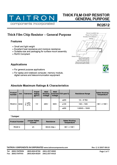
Thick Film Chip Resistor – General PurposeFeatures• Small and light weight• Excellent heat resistance and moisture resistance• Suitable size and packaging for surface mount assembly • RoHS CompliantApplications• For general purpose applications• For laptop and notebook computer, memory module, digital camera and telecommunication equipmentAbsolute Maximum Ratings & CharacteristicsProductNumbermm TolerancePower Rating @70˚CMAX Working Voltage MAXOverload VoltageTCR ppm/℃Resistance RangeRated WorkingTemperature±200 1Ω ~ 9.76Ω±100 10Ω ~ 1M ΩRC2512 6432J: ±5%F: ±1%1W 250V 500V ±2001.02M Ω ~ 10M Ω-55℃~+155℃*JumperProduct NumberJumper RatedCurrentResistanceRated Working Temperature RC2512 4A 50m Ω (Max.)-55℃~+155℃RC2512 Power Derating CurveFor resistors operate in the ambient temperature over 70˚C, loading power ratio will de-rate in accordance with following curve.Soldering ConditionIR Reflow soldering Wave soldering (flow soldering)RC2512 Dimensions (in mm)ProductNumbermm L W H A BAverageWeight RC25126432 6.35 ± 0.203.20± 0.150.55 ± 0.100.60 ± 0.250.50 ± 0.20 40.01 mg Marking(1) ±5% Tolerance (J): 3 digits, the first two digits are significant figures; the third digit is numberof zeros to follow. Letter “R” is as decimal point; Letter “0” for jumper.(2) ±1% Tolerance (F): 4 digits, the first three digits are significant figures; the fourth digit isnumber of zeros. Letter “R” is as decimal point; Letter “0” for jumper.Examples:3 digits marking (±5%)4 digits marking (±1%)683 = 68x103Ω Jumper 6812 = 681x102Ω= 68000 Ω = 68KΩ = 68100 Ω = 68.1KΩ7R5 = 7.5 ΩRC2512 Test and RequirementsRequirement Test Item Test Method Test Condition±1% ±5% JumperTemperature Coefficient of Resistance(T.C.R.) JIS C 5201 4.8IEC 60115-1 4.8-55°C~+155,20°C isthe referencetemperatureWithin the specificationShort Time Overload JIS C 5201 4.13IEC 60115-1 4.132.5 times RCWV or max.overload voltage for 5seconds±(1.0%+0.05Ω) ±(2.0%+0.05Ω) <50mΩInsulation Resistance JIS C 5201 4.6IEC 60115-1 4.6Max. overload voltagefor 1 minute≥10GVoltage Proof JIS C 5201 4.7IEC 60115-1 4.71.42 times RCWV(RMS) for 1 minuteno breakdown or flashoverSubstrate Bending Test JIS C 5201 4.33IEC 60115-1 4.33Bending once with 5seconds for 3 mm±(1.0%+0.05Ω) ±(1.0%+0.05Ω) <50mΩResistance to soldering heat JIS C 5201 4.18IEC 60115 4.18260±5°C for 10 seconds±(0.5%+0.05Ω) ±(1.0%+0.05Ω) <50mΩLeaching JIS C 5201 4.18IEC 60115 4.18260±5°C for 60 seconds no leachingSolderability JIS C 5201 4.17IEC 60115-1 4.17245±5°C for 3 seconds. >95% coverageEndurance at upper category temperature JIS C 5201 4.23IEC 60115-1 2.23.2at +155°C for 1000 hrs ±(1.0%+0.05Ω) ±(1.5%+0.10Ω) <50mΩRapid change of temperature JIS C 5201 4.19IEC 60115-1 4.19-55°C to +155°C, 5cycles±(0.5%+0.05Ω) ±(1.0%+0.05Ω) <50mΩDamp heat with load JIS 5201 4.2440±2°C, 90~95% R.H.or max. working voltagefor 1000 hrswith 1.5hrs “ON” and 0.5hrs “OFF”±(2.0%+0.10Ω) ±(3.0%+0.10Ω) <100mΩEndurance JIS C 5201 4.25IEC 60115-1 4.25.170±2°C, RCWV or Max.working voltage for 1000hrs with 1.5 hrs“ON” and 0.5 hrs “OFF”±(2.0%+0.10Ω) ±(3.0%+0.10Ω) <100mΩNote: RCWV:Rated Continuous Working Voltage.RCWV= √Rated power (W) × Resistance value (R)RC2512 Packing Information:Carrier Tape Dimensions (in mm)Type A B W E F P0 P1 P2 ψD0 ψD0 TRC2512 3.50±0.2 6.70±0.2 12.0±0.3 1.75±0.1 5.5±0.05 4.0±0.1 4.0±0.1 2.0±0.05 1.5+0.1/-0 1.5+0.25/-0Max1.2 Reel Dimensions (in mm)Reel Diameter PCS per Embossed Tape A B C W T7’’ 4,000180+0/-360+1/-013.0±0.213.0±0.515.4±1Carton InformationPCS per Carton Carton Size192,000 400X400X200(inmm)RC2512 How to OrderRC2512 How to contact us:。
FR251 FR252 FR253 FR254 FR255 FR256 FR257二极管中文资料

塑封快恢复整流二极管反向电压 50 ---1000 V正向电流 2.5 AFR251FR252FR253FR254FR255FR256FR2571000501002004006008005010020040060080010003570140280420560700151252.51.35.0200FR251 ...... FR257150300FR251FR252FR253FR254FR255FR256FR257SIYU R最大可重复峰值反向电压Maximum repetitive peak reverse voltage最大均方根电压Maximum RMS voltage最大直流阻断电压Maximum DC blocking voltage最大正向平均整流电流Maximum average forward rectified current峰值正向浪涌电流 8.3ms单一正弦半波Peak forward surge current 8.3 ms single half sine-wave典型热阻 Typical thermal resistance工作结温和存储温度Operating junction and storage temperature range-55 --- +150V V V A A ℃/WV RRMV RMS V DC I F(AV)I FSM ℃Tj, TSTG 极限值和温度特性 TA = 25℃ 除非另有规定。
Maximum Ratings & Thermal Characteristics Ratings at 25℃ ambient temperature unless otherwise specified.符号Symbols单位UnitPlastic Fast Recover RectifierReverse Voltage 50 to 1000VForward Current 2.5A45最大正向电压 最大反向电流 TA= 25℃ TA=100℃最大反向恢复时间I F =0.5A I R =1.0A I RR =0.25A典型结电容 V R = 4.0V, f = 1MHzV μAnS pFI Rtrr C jMaximum forward voltage Maximum reverse currentType junction capacitance电特性 TA = 25℃ 除非另有规定。
台湾天二2512保险丝电阻常用型号查询表
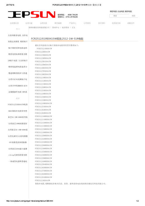
深圳市捷比信科技有限公司 > 资讯中心 > 综合资讯 > 正文捷比信科技将2512贴片保险丝电阻常用型号整理如下:FCR2512J1RE0415WFCR2512J2RE0415WFCR2512J3R6E0415WFCR2512J3R9E0415WFCR2512J5R1E0415WFCR2512J5R6E0415WFCR2512J6R2E0415WFCR2512J7R5E0415WFCR2512J8R2E0415WFCR2512J10RE0415WFCR2512J12RE0415WFCR2512J15RE0415WFCR2512J20RE0415WFCR2512J24RE0415WFCR2512J30RE0415WFCR2512J36RE0415WFCR2512J39RE0415WFCR2512J49R9E0415WFCR2512J51RE0415WFCR2512J62RE0415WFCR2512J82RE0415WFCR2512J100RE0415WFCR2512J110RE0415WFCR2512J120RE0415WFCR2512J130RE0415WFCR2512J150RE0415WFCR2512J180RE0415WFCR2512J200RE0415WFCR2512J220RE0415WFCR2512J240RE0415WFCR2512J280RE0415WFCR2512J300RE0415WFCR2512J330RE0415WFCR2512J360RE0415WFCR2512J390RE0415WFCR2512J490RE0415WFCR2512J504RE0415WFCR2512J620RE0415WFCR2512J750RE0415WFCR2512J820RE0415WFCR2512J910RE0415WFCR2512J1KE0415W保险丝电阻,熔断器更多相关信息,查货,索样请来电洽询深圳市捷比信科技有限公司。
TH2512+直流低电阻测试仪使用说明书
使用说明书OPERATION MANUALTH2512+/TH2512A+/TH2512B+智能直流低电阻测试仪TH2512+ DC Low Ohmmeter************目录第1章概述................................................................................................................................. 1-11.1引言................................................................................................................................. 1-11.2使用条件 ......................................................................................................................... 1-1电源 ....................................................................................................................................................................... 1-1 环境温度与湿度..................................................................................................................................................... 1-2 预热............................................................................................................................................................................ 1-2 几点注意问题 ......................................................................................................................................................... 1-21.3体积与重量...................................................................................................................... 1-21.4安全要求 ......................................................................................................................... 1-2绝缘电阻................................................................................................................................................................... 1-3 绝缘强度................................................................................................................................................................... 1-3 泄漏电流................................................................................................................................................................... 1-31.5电磁兼容 ......................................................................................................................... 1-3电源瞬态敏感度按GB6833.4的要求。
铸钢25锰

铸钢25锰全文共四篇示例,供读者参考第一篇示例:铸钢25锰是一种含有较高锰含量的铸钢材料,具有优异的机械性能和耐磨性,广泛应用于工程机械、矿山机械、破碎机械等领域。
铸钢25锰在生产和加工过程中具有一定的技术难度,但一旦掌握了正确的制作方法和工艺,就能够为企业带来良好的经济效益和社会效益。
1. 铸钢25锰的化学成分和性能特点铸钢25锰是一种含有25%左右锰元素的合金钢材料,主要由铁、碳、锰等元素组成。
其主要特点包括:硬度高、强度大、韧性好、耐磨性强、抗冲击性好等。
这些性能使得铸钢25锰在高强度、高耐磨、高冲击负荷等场合中有着广泛的应用前景。
2. 铸钢25锰的生产工艺铸钢25锰的生产工艺主要包括材料准备、熔炼、浇铸、热处理等几个环节。
首先是材料准备,需要选用优质的原料,如高锰矿、高碳铁等,保证材料的纯度和配比的准确性。
然后是熔炼,将原料放入炉中进行加热,熔化后进行调温和脱气处理,使合金得到适当的组织和性能。
接着是浇铸,将熔融的合金倒入模具中,进行成型。
最后是热处理,通过适当的加热、冷却、回火等工艺,调整合金的组织和性能,提高其综合性能和稳定性。
3. 铸钢25锰的应用领域铸钢25锰具有良好的材料性能,广泛应用于工程机械、矿山机械、冶金机械、破碎机械、水泥机械、化工机械、船舶舾装、石料生产线等领域。
在这些领域中,铸钢25锰常用于制造机械零部件,如破碎齿板、衬板、锤头、磨板等,这些零部件对材料的机械性能和耐磨性要求较高,铸钢25锰能够满足这些要求,并具有较长的使用寿命和良好的性价比。
4. 铸钢25锰的经济效益和社会效益铸钢25锰由于其较高的生产难度和成本,在生产和加工中要求严格,但一旦掌握了正确的生产工艺和技术,就能够为企业带来良好的经济效益和社会效益。
铸钢25锰具有较长的使用寿命和良好的性能,能够减少设备维修和更换零部件的频率,降低企业的生产成本。
铸钢25锰产品质量可靠,性能稳定,能够提高设备的生产效率和产品质量,增强企业的竞争力。
STTA2512资料

ISOTOP and TURBOSWITCH are trademarks of STMicroelectronics.November 1999-Ed:4BULTRA-FAST,SOFT RECOVERY.VERY LOW OVERALL POWER LOSSES IN BOTH THE DIODE AND THE COMPANION TRANSISTOR.HIGH FREQUENCY AND/OR HIGH PULSED CURRENT OPERATION.HIGH REVERSE VOLTAGE CAPABILITY.LOW INDUCTANCE PACKAGE <5nH.INSULATED PACKAGE:ISOTOP TM Electrical insulation :2500V RMS Capacitance:<45pF.FEATURES AND BENEFITSTURBOSWITCH 1200V drastically cuts losses in all high voltage operationswhich require extremely fast,soft and noise-free power diodes.Due to their optimized switching performances they also highly decrease power losses in any associated switching IGBT or MOSFET in all freewheel mode operations.They are particularly suitable in Motor Control circuitries,or in the primary of SMPS as snubber,clamping or demagnetizing diodes.They are also suitable for secondary of SMPS as high voltage rectifier diodes.DESCRIPTIONI F(AV)25A V RRM 1200V t rr (typ)60ns V F (max)1.9VMAIN PRODUCT CHARACTERISTICSSymbol ParameterValue Unit V RRM Repetitive peak reverse voltage 1200V I F(RMS)RMS forward current50A I FRM Repetitive peak forward current tp =5µs F =5kHz square 300A I FSM Surge non repetitive forward current tp =10ms sinusoidal210A T stg Storage temperature range-65to +150°C T jMaximum operating junction temperature150°CABSOLUTE RATINGS (limiting values,per diode)STTA2512P STTA5012TV1/2®TURBOSWITCH ™ULTRA-FAST HIGH VOLTAGE DIODEISOTOP TMK2A2K1A1STTA5012TV1K2K1A1A2STTA5012TV2KKA SOD93STTA2512P1/9Symbol Parameter Test conditionsMinTyp MaxUnit t rrReverse recovery timeTj =25°CI F =0.5A I R =1AIrr =0.25A I F =1A dI F /dt =-50A/µs V R =30V 60110nsI RMMaximum reverse recovery current Tj =125°C VR =600V I F =25AdI F /dt =-200A/µs dI F /dt =-500A/µs 4535AS factorSoftness factorTj =125°C V R =600V I F =25AdI F /dt =-500A/µs1.2/DYNAMIC ELECTRICAL CHARACTERISTICS (per diode)TURN-OFF SWITCHING Symbol ParameterTest conditions MinTypMax Unit t frForward recovery timeTj =25°CI F =25A,dI F /dt =200A/µs measured at 1.1×V F max 900nsV Fp Peak forward voltageTj =25°CI F =25A,dI F /dt =200A/µs I F =40A,dI F /dt =500A/µs3530VTURN-ON SWITCHING Symbol ParameterTest conditions Min Typ Max Unit V F *Forward voltage drop I F =25A Tj =25°C Tj =125°C 1.3 2.11.9V V I R **Reverse leakage current V R =0.8x V RRM Tj =25°C Tj =125°C 2.01508µA mA V to Threshold voltage Ip <3.I F(AV)Tj =125°C1.52V R dDynamic resistance15m ΩTest pulses :*tp =380µs, δ<2%**tp =5ms ,δ <2%STATIC ELECTRICAL CHARACTERISTICS (per diode)To evaluate the maximum conduction losses use the following equation :P =V to x I F(AV)+Rd x I F 2(RMS)Symbol ParameterConditions Value Unit R th(j-c)Junction to case thermal resistanceISOTOP Per diode 1.4°C/WISOTOP Total 0.75SOD93 1.2R th(c)Coupling thermal resistance ISOTOP Coupling 0.1°C/W P 1Conduction power dissipation I F(AV)=25A δ=0.5ISOTOP Tc=70°C 57W SOD93Tc=82°C P maxTotal power dissipationPmax =P1+P3(P3=10%P1)ISOTOP Tc=62°C 62.5W SOD93Tc=75°CTHERMAL AND POWER DATA (per diode)STTA2512P /STTA5012TV1/22/951015202530102030405060IF(av)(A)P1(W)δ=1δ=0.5δ=0.2δ=0.1Tδ=tp/TtpFig.1:Conduction losses versus average current (per diode).0.00.5 1.0 1.5 2.0 2.5 3.0 3.5 4.0110100300VFM(V)IFM(A)Tj=125°CFig.2:Forward voltage drop versus forward current (maximum values,per diode).1E-31E-21E-11E+05E+00.00.20.40.60.81.0tp(s)Zth(j-c)/Rth(j-c)δ=0.2δ=0.5Single pulseδ=0.1Fig.3-1:Relative variation of thermal impedance junction to case versus pulse duration (per diode)(ISOTOP).1E-41E-31E-21E-11E+00.00.20.40.60.81.0tp(s)Zth(j-c)/Rth(j-c)δ=0.1δ=0.2δ=0.5Single pulseFig.3-2:Relative variation of thermal impedance junction to case versus pulse duration (SOD93).10020030040050050100150200250300350400450500trr(ns)VR=600V Tj=125°CIF=2*IF(av)IF=IF(av)IF=0.5*IF(av)dIF/dt(A/µs)Fig.5:Reverse recovery time versus dI F /dt (90%confidence,per diode).100200300400500510152025303540455055IRM(A)VR=600V Tj=125°CIF=2*IF(av)IF=0.5*IF(av)IF=IF(av)dIF/dt(A/µs)Fig.4:Peakreverse recoverycurrent versus dI F /dt (90%confidence,per diode).STTA2512P /STTA5012TV1/23/91002003004005000.801.001.201.401.60S factor IF<2*IF(av)VR=600VTj=125°CdIF/dt(A/µs)Fig.6:Softness factor (tb/ta)versus dI F /dt (typical values,per diode).2550751001250.70.80.91.01.1Tj(°C)IRMS factorFig.7:Relative variation of dynamic parameters versus junction temperature (reference Tj=125°C).100200300400500102030405060VFP(V)Tj=125°CIF=IF(av)dIF/dt(A/µs)Fig.8:Transient peak forward voltage versus dI F /dt (90%confidence,per diode).100200300400500200400600800100012001400tfr(ns)Tj=125°CVFR=1.1*VF max.IF=IF(av)dIF/dt(A/µs)Fig.9:Forward recovery time versus dI F /dt (90%confidence,per diode).STTA2512P /STTA5012TV1/24/9Fig.A :”FREEWHEEL”MODE.TOTAL LOSSES due to the diodeP =P1+P2+P3+P4+P5WattsSWITCHING LOSSES in the diodeSWITCHING LOSSES in the tansistor due to the diodeCONDUCTION LOSSES in the diode REVERSE LOSSES in the diode The 1200V TURBOSWITCH series has been designed to provide the lowest overall power losses in all high frequency or high pulsed current operations.In such applications (Fig A to D),the way of calculating the power losses is given below :APPLICATION DATADIODE:TURBOSWITCHILLOADTRANSISTORSWITCHING tpTF =1/Tδ=tp/TV RSTTA2512P /STTA5012TV1/25/9I I FRdI RV RV toV FVFig.E:STATIC CHARACTERISTICSConduction losses :P1=V to .I F(AV)+R d .I F 2(RMS)Max values at 125°C,suitablefor Ipeak <3.IF(av)Reverse losses :P2=V R .I R .(1-δ)tp TF =1/Tδ=tp/TPWMFig.B :SNUBBER DIODE.Fig.C :DEMAGNETIZING DIODE.Fig.D :RECTIFIER DIODE.STATIC &DYNAMIC CHARACTERISTICS .POWER LOSSES.STTA2512P /STTA5012TV1/26/9Turn-on losses :(in the transistor,due to the diode)P5=V R ×I RM 2×(3+2×S )×F6x dI F ⁄dt+V R ×I RM ×I L ×(S +2)×F 2x dI F ⁄dtTurn-off losses (in the diode):P3=V R ×I RM 2×S ×F6x dI F ⁄dtTurn-off losses :(with non negligibleserial inductance)P3’=V R ×I RM 2×S ×F6x dI F ⁄dt +L ×I RM 2×F2P3,P3’and P5are suitable for powerMOSFET and IGBTFig.F:TURN-OFF CHARACTERISTICSI FV F V Fp1.1V FV F F dI /dtttI FmaxtfrFig.G:TURN-ON CHARACTERISTICSTurn-on losses :P4=0.4(V FP -V F ).I Fmax .t fr .FAPPLICATION DATA (Cont’d)dI F /dt =V R /LdI /dtR tbta I RMV RIVtS =tb/tatrr =ta +tb RECTIFIER OPERATIONVIILtTRANSISTORdI /dtF dI /dtR tbta I RMVRDIODEIVttrr =ta +tbS =tb /ta STTA2512P /STTA5012TV1/27/9PACKAGE MECHANICAL DATA ISOTOPREF.DIMENSIONS Millimeters Inches Min.Max.Min.Max.A11.8012.200.4650.480A18.909.100.3500.358B7.88.200.3070.323C0.750.850.0300.033C2 1.95 2.050.0770.081D37.8038.20 1.488 1.504D131.5031.70 1.240 1.248E25.1525.500.990 1.004E123.8524.150.9390.951E224.80typ.0.976typ.G14.9015.100.5870.594G112.6012.800.4960.504G2 3.50 4.300.1380.169F 4.10 4.300.1610.169F1 4.60 5.000.1810.197P 4.00 4.300.1570.69P1 4.00 4.400.1570.173S30.1030.30 1.185 1.193 STTA2512P/STTA5012TV1/28/9Information furnished is believed to be accurate and reliable.However,STMicroelectronics assumes no responsibility for the consequences of use of such information nor for any infringement of patents or other rights of thirdparties which may result from its use.No license is granted by implication or otherwise under any patent or patent rights of STMicroelectronics.Specifications mentioned in this publication are subject to change without notice.This publication supersedes and replaces all information previously supplied.STMicroelectronics products are not authorized for use as critical components in life support devices or systems without express written ap-proval of STMicroelectronics.The ST logo is a registered trademark of STMicroelectronics ©1999STMicroelectronics -Printed in Italy -All rights reserved.STMicroelectronics GROUP OF COMPANIESAustralia -Brazil -China -Finland -France -Germany -Hong Kong -India -Italy -Japan -MalaysiaMalta -Morocco -Singapore -Spain -Sweden -Switzerland -United Kingdom -U.S.A.PACKAGE MECHANICAL DATA SOD93REF.DIMENSIONSMillimetersInchesMin.Typ.Max.Min.Typ.Max.A 4.70 4.900.1850.193C 1.171.370.0460.054D 2.500.098D1 1.270.050E 0.500.780.0200.031F 1.101.300.0430.051F3 1.750.069G 10.8011.100.4250.437H 14.7015.200.5780.598L 12.200.480L216.200.638L318.00.709L5 3.954.150.1560.163L631.001.220O4.00 4.100.1570.161Ordering type Marking Package Weight Base qty Delivery modeSTTA5012TV1STTA5012TV1ISOTOP 27g.without screws10Tube STTA5012TV2STTA5012TV2ISOTOP 10Tube STTA2512PSTTA2512PSOD933.79g.30TubeCooling method:by conduction(C)ISOTOP recommended torque value:1.3N.m.(MAX 1.5N.m.)for the 6x M4screws.(2x M4screws recommended for mounting the package on the heatsink and the 4screws for terminals).ISOTOP:the screws supplied with the package are suitable for mounting on a board with a thickness of 0.6mm min and 2.2mm max.Epoxy meets UL94,V0STTA2512P /STTA5012TV1/29/9。
合金电阻2512

合金电阻2512全文共四篇示例,供读者参考第一篇示例:合金电阻2512是一种常用的电子元件,它广泛应用于电子设备和电路中。
合金电阻2512具有较高的精度和稳定性,能够准确地控制电流和电压,为电子设备提供稳定的工作环境。
本文将介绍合金电阻2512的基本特性、应用领域以及制作工艺。
一、基本特性合金电阻2512是一种薄膜型电阻,其尺寸为2.5mm x 1.2mm,厚度为0.5mm。
它的外壳材料一般采用有机高分子绝缘材料,内部则使用铜镍合金等材料制成。
合金电阻2512具有较高的工作温度范围,通常能够耐受-55℃至+155℃之间的温度变化。
合金电阻2512还具有较高的耐腐蚀性能,能够在恶劣的环境条件下长时间稳定工作。
二、应用领域合金电阻2512广泛应用于电子设备和电路中,主要用于电流限制、电压分压、信号调节等功能。
在现代电子产品中,合金电阻2512被广泛应用于智能手机、平板电脑、数码相机、电视机等消费电子产品中,起到关键的作用。
在通信、医疗、工控等行业中,合金电阻2512也被广泛应用于各类设备和系统中。
三、制作工艺合金电阻2512的制作工艺主要包括薄膜沉积、光刻、腐蚀、离子注入等步骤。
在基板上沉积一层合金材料,然后通过光刻技术进行图案形成,接着进行腐蚀处理,最后进行离子注入和封装,最终得到合金电阻2512。
制作过程需要精密的设备和技术支持,以确保电阻器的精度和稳定性。
四、未来发展趋势第二篇示例:合金电阻2512是一种常见的电子元件,常用于电路中的电阻器。
它是由合金材料制成的,具有一定的电阻值和功率耗散能力。
在现代电子设备中,合金电阻2512被广泛应用于各种电路中,起着限流、分压、分流等重要作用。
合金电阻2512的主要特点是具有稳定的温度特性和高功率耗散能力。
它的电阻值一般在几欧姆到几十欧姆之间,功率耗散能力可达几瓦特以上。
这使得合金电阻2512能够在较高的电流和电压下正常工作,不易受外界环境的影响。
合金电阻2512的封装尺寸为2512,即长2.5mm,宽1.2mm。
