lec06b-Cache Memory
华三路由器软件升级指南
开机自检时出现问题后会出现的BIOS语句
开机自检时出现咨询题后会出现各种各样的英文短句,短句中包含了特不重要的信息,读明白这些信息能够自己解决一些小咨询题,然而这些英文难倒了一局部朋友,下面是一些常见的BIOS短句的解释,大伙儿能够参考一下。
〔1〕.CMOSbatteryfailed中文:CMOS电池失效。
解释:这讲明CMOS电池差不多快没电了,只要更换新的电池即可。
〔2〕.CacheMemoryBad,DoNotenableCache解决方法:主板高速缓存损坏导致,寻售后解决〔3〕.CMOSchecksumerror-Defaultsloaded中文:CMOS执行全部检查时发现错误,要载进系统预设值。
解释:一般来讲出现这句话根基上讲电池快没电了,能够先换个电池试试,要是咨询题依旧没有解决,那么讲明CMOSRAM可能有咨询题,要是没过一年就到经销商处换一块主板,过了一年就让经销商送回生产厂家修一下吧!〔4〕.CMOSChecksumErrordefaultsloaded解决方法:也有可能是电池没有电所致,然而更换后还出现那个咨询题,有可能是CMOS数据错误或主板电容咨询题,寻售后〔5〕.解决方法:Boot.ini文件中的代码被更改,能够将下面的代码保持到c:\boot.ini 中[bootloader]-timeout=10/default=multi(0)disk(0)rdisk(0)partition(1)\WINDOWS[operatingsystems]multi(0)disk(0)rdisk(0)partition(1)\WINDOWS="MicrosoftWindowsXPPro fessional"/NOEXECUTE=OPTIN/FASTDETECT〔6〕.PressESCtoskipmemorytest中文:正在进行内存检查,可按ESC键跃过。
解释:这是因为在CMOS内没有设定跃过存储器的第二、三、四次测试,开机就会执行四次内存测试,因此你也能够按ESC键结束内存检查,只是每次都要如此太苦恼了,你能够进进COMS设置后选择BIOSFEATURSSETUP,将其中的QuickPowerOnSelfTest设为Enabled,储存后重新启动即可。
跑马灯代码表
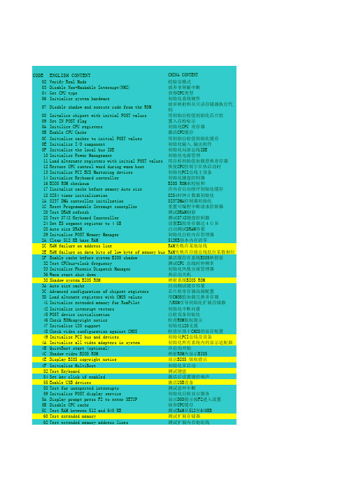
CODE ENGLISH CONTENT CHINA CONTENTO2Verify Real Mode校验实模式O3Disable Non-Maskable Internupt(NMI)放弃非屏蔽中断O4Get CPU type获得CPU类型O6Initialize system hardware 初始化系统硬件O7Disable shadow and execute code from the ROM放弃映射和从只读存储器执行代码 O8Initalize chipset with initial POST valucs用初始自检值初始化芯片组O9Set IN POST flag置入自检标示OA Initilize CPU registers初始化CPU 寄存器OB Enable CPU Cache激活CPU缓存OC Initialize caches to initial POST values用初始自检值初始化缓存OE Initialize I/O component初始化输入,输出组件OF Initialize the local bus IDE初始化局部总线IDE 10Initialize Power Management初始化电源管理11Load alternate registers with initial POST values用自检初始值加载替换寄存器12Restore CPU control word during warm boot恢复CPU控制字在热启动时13Initialize PCI BUS Mastering devices初始化PCI总线主设备14Initialize Keyboard controller初始化键盘控制器16BIOS ROM checksum BIOS ROM求校验和17Iinitalize cache before memory Auto size在内存自动排序初始化缓存188254 timer initialization8254时钟计数器初始化1A8237 DMA controller initilzation8237DMA控制器初始化1C Reset Programmable Intemupt conntpller重置可编程中断请求控制器20Test DRAM refresh测试DRAM刷新22Test 8742 Keyboard Conntroller测试8742键盘控制器24Set ES segment register to 4 GB设置ES段寄存器达4GB28Auto size DRAM自动测试DRAM容量29Initialize POST Memory Manager初始化自检内存管理器2A Clear 512 KB base RAM512KB基本内存清零2C RAM failure on address line RAM失败在某地址线2E RAM failure on data bits of low byte of memory bus RAM失败在存储总线低位某数据位 2F Enable cache before system BIOS shadow激活缓存在系统BIOS映射前32Test CPUbus-clock freguency测试CPU 总线时钟频率33Initialize Phoenix Dispatch Manager初始化凤凰分派管理器36Warm start shut down热启动关机38Shadow system BIOS ROM映射系统BIOS ROM3A Auto size cache自动测试缓存容量3C Advanced configuration of chipset registers芯片组寄存器高级配置3D Load altrnate registers with CMOS values用CMOS值加载交换寄存器41Initialize extended memory for RomPilot为ROM引导初始化扩展存储器42Initialize interrupt vectors初始化中断向量45POST device initialization自检设备初始化46Check ROMcopyright notice检查ROM版权提示47Initialize 120 support初始化120支援48Check video configuration against CMOS检查区别于CMOS的显存配置49Initialize PCI bus and devices初始化PCI总线及设备4A Initialize all video adapters in system初始化所有系统内的显示适配器 4B QuietBoot start (optional)冷启动开始4C Shadow video BIOS ROM映射ROM内显示BIOS4E Display BIOS copyright notice显示BIOS 版权提示4F Initialize MultiBoot初始化多启动52Test Keyboard测试键盘54Set key click if enabled激活后设置键控响声55Enable USB devices激活USB设备58Test for unexpected interrupts测试意外中断59Initialize POST display service初始化自检显示服务5A Display prompt press F2 to enter SETUP显示DOS提示按F2进入设置5B Disable CPU cache放弃CPU缓存5C Test RAM between 512 and 640 KB测试RAM从512至640KB 60Test extended memory测试扩展存储器62Test ectended memory address lines测试扩展内存地址线64Jump to UserPatch1跳至用户补丁区166Configure advanced cache registers配置高级缓存寄存器67Initialize Multi Processor APIC初始化多处理器APIC68Enable external and CPU caches激活外接和CPU缓存69Display system Management Mode (SMM)area显示系统管理模式区6A Display external L2 cache size 显示外接L2缓存容量6B Load custom defaults(optional)加载用户默认值6C Dislay shadow-area message显示映射区信息6E Display possible high address for UMB recover显示可能的高端地址为UMB恢复使用70Display error messages显示错误信息72Check for configuation errors检测配置偏差76Check for keyboard errors检测键盘错误7C Set up tard ware interrupt vectors设置硬件中断向量7D Initialize Intelligent System Monitoring初始化智能系统跟踪7E Initialize coprocessor if present如果存在,初始化协处理器80Disable onboard Super I/O ports and IRQS放弃板上的超级输入输出端口及IRQS 81Late POST device initialization最后自检设备的初始化82Detect and install extemal RS232 ports侦测安装外接RS232端口83Configure non-MCD IDE controllers配置NON-MCD IDE控制器84Detect and installextermal parallel ports侦测安装外接并行端口85Initialize PC-compatible PnP ISA devices初始化兼容PC即插即用ISA设备86Re-initialize onblard I/O Ports重初始化板上的输入输出端口87Configure Motherboard Configurable Devices(optional)配置M/B可配置设备88Initializ BIOS Data area BOIS数据区初始化89Enable mon-maskable inteerupts[NMIS]激活非屏蔽中断请求8A Initializ Extended Bios Data Area扩展BIOS数据区初始化8b Test and initialize PS/2 mouse测试和初始化PS/2端口8C Initialize floppy controller初始化软驱控制器8F Determine number of ATA drives (optional)测试ATA驱动器数量90Initialize hard-disk controllers初始化硬盘驱控制器91Initialize local-bus bard-disk countrollers初始化局部总线上的硬盘控制器92Jump to Userpatch2跳至用户补丁区93Build MPTABLE for multi-processor boards为多处理器板建立多处理器列表95Install CD-ROM for boot为启动安装CD-ROM96Clear hUge ES segment register清空大量ES段寄存器97Fix up Multi Procssor table设置多处理器列表98Scarch for option ROMs,One long,授索可选只读存储器,一长,二two short beeps on checksum failure短嗡鸣声,在校验失败时99Check for SMART Drive(optional)检查SMART驱动器9A Shadow option ROMs映射选定的只读存储器9C Set up power Management设置电源管理9D Initialize security engine(oprional)初始化安防措施9E Enable bardware interrupts激活硬件中断9F Determine number of ATA and SCDI drives 检测A/A和SCDI设备数量A0Set time or day设置时间和日期A2Check key lock检查锁定键A4Initialize typebatic rateA8Erase F2 prompt清除F2提示AA Scan for F2 key stroke扫描有无F2键按下AC Enter SETUP进入设置AE clear boot flag清除启动标志B0Check for errors检查错误B1Inform Rom pilot about the end of POST通知只读存储器在自检结束后引导系统 B2POST done-prepare to boot operating system自检结束准备起动系统B4One short beep before boot起动前一个短嗡鸣声B5Terminate QuietBoot(optional)结束冷启动B6Check passwont(potional)检验密码B7Initialize ACPIBIOS初始化ACPIBIOSB9Prepare Boot准备启动BA Initialize SMBIOS初始化SMBIOSBB Initialize PuP Option ROMs初 始化即插即用只读存储器BC Clear parity checkers清零奇偶校验检测BD Display MultiBoot menu显示多启动菜单BE Clear screen (Optional)清空显示屏BF Check virus and backup reminders检查病毒备份提示C0Try to boot with INT 19试用INT 19启动C1Initialize POST Error Manager初始化自检管理C2Initialize error logging初始化错误日志C3Initialize error display function初始化错误显示功能C4Initialize system error bandler初始化系统错误处理C5PnPnd dual CMOS(optional)C6Initialize note disk (optional)C7Initialize note dock lateC8Force check(optional)强行检查CC Redirect Int 10h to ENable remote serial video重指示INT 10去激活远程窜行显示 CD Re_map I/O and memory for PCMCIA重定位I/O和内存为PCMCIA卡CE Initialize digitize and display message初始化数字的显示信息D2Unknowm interrupt不明中断The followIng are for boot block in Flash ROME0Initialize the chipset初始化芯片组E1Initialize the bridge初始化桥E2Iinitalize the CPU初始化CPUE3Initialize system timer初始化系统时钟E4Initialize system I/0初始化系统输入输出口E5Check force reCovery boot检查强行恢复启动E6Checksum BIOSROM BIOS ROM求校验和E7Go to BIOS转向BIOSE8Set Hune Segment设置大量段寄存器E9Initialize Multi procssor初始化多处理器EA Initialize OEMspectal code初始化OEM专用代码EB Initialize PIC and DMA初始化PIC 和DMAEC Initialize Memory type初始化存储类型ED Initialize Memory size初始化存储容量EE Shadow Boot Block映射启动模块EF System memory test系统存储器测试F0Initilize intemupt vectors初始化中断向量F1Initilize Run Time Clock初始化运行时钟F2Initilize video初始化显示F3Initilize System Management Manager初始化系统管理的管理器F4Output one beep输出一个嗡鸣声F5Clear Huge Seginent清空大量段寄存器F6Boot to Mini DOS最小化DOS启动F7Boot to Full DOS完整DOS启动。
如何选择一款“极耐寒”的非易失性内存
如何选择一款“极耐寒”的非易失性内存首先想要给烧友们介绍下什么是非易失性内存?是指当电流关掉后,所存储的数据不会消失者的电脑存储器。
非易失性存储器中,依存储器内的数据是否能在使用电脑时随时改写为标准,可分为二大类产品,即ROM和Flash memory。
ROM(Read-only memory,只读内存)PROM(Programmable read-only memory,可编程只读内存)EAROM(Electrically alterable read only memory,电可改写只读内存)EPROM(Erasable programmable read only memory,可擦可编程只读内存)EEPROM(Electrically erasable programmable read only memory,电可擦可编程只读内存)Flash memory(闪存)那么非易失性内存的运行环境又是怎么样的呢?根据数据统计普通内存的运行稳定温度是-30摄氏度左右,而富士通电子元器件(上海)有限公司推出新款64-Kbit FRAM ——MB85RS64TU。
该款内存能在-55℃中正常运行,为富士通电子旗下首款能耐受如此低温的FRAM 非易失性内存,现已量产供货。
相信烧友们也一样对这款能在超低温下运行的内存十分感兴趣,那我们接下来就走进其世界一起去探究下。
MB85RS64TU 支持 1.8V 至 3.6V 的极广范围电源电压。
其工作温度更是超越竞争对手,最低达到-55℃。
由于它能在运行温度范围内保证10兆次的读/写周期,故适合用于在极寒地区挖掘天然气与石油的设备、机械等产业机械。
MB85RS64TU 也适用于例如测量设备、流量计、及机器人等的一般工业应用。
20年来,富士通量产各种FRAM 非易失性内存产品,具备高速写入运行、极高的读/写耐用度、及低功耗等特色。
值得一提的是,FRAM 产品保证10兆次的读/写周期,约为非易失性内存EEPROM 的1千万倍。
华为s2300 系列vlan配置实例
华为s2000 系列vlan 配置实例第一次使用需要用配置线把com1口和console口进行连接。
BIOS LOADING ...*********************************************************** *** Copyright (c) 2008-2009 HUAWEI TECH CO., LTD. * *********************************************************** **Board Name ....................................... CX22EFFEDDR SDRAM size ................................... 64MBDDR SDRAM test ................................... passPress Ctrl+T to start DDR SDRAM full test in 2 secondsStarting...Decompress advanced BOOTROM..............doneLoading advanced BOOTROM...************************************************* ** Advanced BOOTROM, Ver113 ** *************************************************Copyright (c) 2008-2009 HUAWEI TECH CO., LTD.Creation date: Apr 6 2009, 18:15:08CPU L1 Cache : 16KBCPU Clock Speed : 200MHzBus Clock Speed : 100MHzMemory Size : 64MB//连接后显示的硬件配置信息Press Ctrl+B to enter BOOTROM menu 0Auto-booting...Decompressing VRP software...doneInitialize switch chipInitialize DOPRA rootInitialize hardwareInitialize VOS VFSInitialize VOS monitorInitialize CFMInitialize device linkCreate VRP taskInitialize VRP taskRegister command linesAwake taskRecover configuration.......doneConsole 0 is availablePress ENTER to start<Quidway>dis cur //显示当前配置信息#sysname Quidway#vlan batch 1 to 25#bpdu enable#cluster enablentdp enableJan 1 2008 00:03:35 Quidway %%01VFS/4/LOG_IS_SA VING(l): System monitor log is saving.ntdp hop 16ndp enable#voice-vlan mac-address 0001-e300-0000 mask ffff-ff00-0000 description Simens phvoice-vlan mac-address 0003-6b00-0000 mask ffff-ff00-0000 description Cisco phonevoice-vlan mac-address 0004-0d00-0000 mask ffff-ff00-0000 description Avaya phonevoice-vlan mac-address 0060-b900-0000 mask ffff-ff00-0000 description Philips/NEC phonevoice-vlan mac-address 00d0-1e00-0000 mask ffff-ff00-0000 description Pingtel phonevoice-vlan mac-address 00e0-7500-0000 mask ffff-ff00-0000 description Polycom phonevoice-vlan mac-address 00e0-bb00-0000 mask ffff-ff00-0000 description 3com phone#//通过以下配置使vlan接口各个端口通过此上网vlan 25description administratorvlan //端口描述interface Vlanif1#interface Ethernet0/0/1port default vlan 1ntdp enablendp enable#interface Ethernet0/0/2port default vlan 2ntdp enablendp enable#interface Ethernet0/0/3port default vlan 3ntdp enablendp enable#---- More ----Jan 1 2008 00:03:43 Quidway %%01VFS/4/LOG_IS_SA VED(l): System monitor log is sainterface Ethernet0/0/4port default vlan 4 ntdp enablendp enable#interface Ethernet0/0/5 port default vlan 5 ntdp enablendp enable#interface Ethernet0/0/6 port default vlan 6 ntdp enablendp enable#interface Ethernet0/0/7 port default vlan 7 ntdp enablendp enable#interface Ethernet0/0/8 port default vlan 8 ntdp enablendp enable#interface Ethernet0/0/9 port default vlan 9 ntdp enablendp enable#interface Ethernet0/0/10 port default vlan 10 ntdp enablendp enable#interface Ethernet0/0/11 port default vlan 11 ntdp enablendp enable#interface Ethernet0/0/12 port default vlan 12 ntdp enablendp enable#interface Ethernet0/0/13 port default vlan 13 ntdp enablendp enable#interface Ethernet0/0/14 port default vlan 14 ntdp enablendp enable#interface Ethernet0/0/15 port default vlan 15 ntdp enablendp enable#interface Ethernet0/0/16 port default vlan 16 ntdp enablendp enable#interface Ethernet0/0/17 port default vlan 17ntdp enablendp enable#interface Ethernet0/0/18 port default vlan 18 ntdp enablendp enable#interface Ethernet0/0/19 port default vlan 19 ntdp enablendp enable#interface Ethernet0/0/20 port default vlan 20 ntdp enablendp enable#interface Ethernet0/0/21 port default vlan 21 ntdp enablendp enable#interface Ethernet0/0/22port default vlan 22ntdp enablendp enable#interface Ethernet0/0/23port default vlan 23ntdp enablendp enable#interface Ethernet0/0/24port default vlan 24ntdp enablendp enable#interface GigabitEthernet0/0/1port default vlan 25port trunk allow-pass vlan 1 to 4094 ntdp enablendp enable#interface GigabitEthernet0/0/2port default vlan 25port trunk allow-pass vlan 1 to 4094 ntdp enablendp enable#interface NULL0#aaaauthentication-scheme default#authorization-scheme default#accounting-scheme default#domain default##ip route-static 0.0.0.0 0.0.0.0 175.20.0.1 #user-interface con 0user-interface vty 0 4# return。
HP StorageWorks HSG60 和 HSG80 外部缓存电池(ECB)替换指南(第六版)

HP StorageWorks Replacing an HSG60and HSG80 External Cache Battery (ECB)Replacing an HSG60 and HSG80 External Cache Battery (ECB) Installation InstructionsSixth Edition (March 2005)Part Number: EK-80ECB-IM. F01© Copyright 2000–2005 Hewlett-Packard Development Company, L.P .Hewlett-Packard Company makes no warranty of any kind with regard to this material, including, but not limited to, the implied warranties of merchantability and fitness for a particular purpose. Hewlett-Packard shall not be liable for errors contained herein or for incidental orconsequential damages in connection with the furnishing, performance, or use of this material.This document contains proprietary information, which is protected by copyright. No part of this document may be photocopied, reproduced, or translated into another language without the prior written consent of Hewlett-Packard. The information contained in this document is subject to change without notice.Microsoft®, MS Windows®, Windows®, and Windows NT® are U.S. registered trademarks of Microsoft Corporation.Product names mentioned herein may be trademarks of their respective companies as reflected by an associated footnote.Hewlett-Packard Company shall not be liable for technical or editorial errors or omissions contained herein. The information is provided “as is” without warranty of any kind and is subject to change without notice. The warranties for Hewlett-Packard Company products are set forth in the express limited warranty statements for such products. Nothing herein should be construed as constituting an additional warranty.Printed in the U.S.A.Read instructions completely before beginning the installation procedureAbout these instructionsThis document contains instructions for replacing the ECB in an HP StorageWorks HSG60 or HSG80 subsystem.For instructions on upgrading a single-controller configuration to a dual-redundant controller configuration, refer to the appropriate array controller user guide or maintenance and service guide.ECB replacement procedures provided in these instructions include:■Replacing an ECB in HP StorageWorks Model BA370 enclosures , page 1■Replacing an ECB in HP StorageWorks Model 2100 and 2200 enclosures , page 2■Replacing an ECB in HP StorageWorks Model 2100 and 2200 enclosures using hot-pluggable procedure , page 3General informationThe type of ECB used depends on the HP StorageWorks controller enclosure type.WARNING: The ECB is a sealed, rechargeable, lead acid battery that must be recycled or disposed of properly according to local regulations or policies afterreplacement. Do not incinerate the battery. Improperhandling may cause personal injury. The ECB displays the following label:Replacing an ECB in HP StorageWorks Model BA370 enclosuresFigure 1 and Figure 2 provide information about the ECBs used in HP StorageWorks model BA370 controller enclosures.Figure 1: Single ECB for single-controller configurations in a BA370 enclosure1Battery disable switch (shutoff)2Status LED 3ECB Y-cableFigure 2: Dual ECB for dual-redundant controller configurations in a BA370 enclosureUse the following steps including Figure1 (on page1) and Figure2, as appropriate, to replace an ECB in single-controller and dual-redundant controller configurations using the Field Replacement Utility (FRUTIL):1.Connect a PC or terminal to the maintenance port of thecontroller with the defective ECB.The controller connected to the PC or terminal becomes“this controller.”2.Verify the system time setting by entering the followingcommand:SHOW THIS_CONTROLLER FULL3.If the system date and time is not set or current, entercurrent date and time by entering the following command: SET THIS_CONTROLLER TIME=dd-mm-yyyy:hh:mm:ssNote: An internal clock monitors the life of the ECB battery. This clock is automatically reset as part of the FRUTIL procedure.4.Start FRUTIL with the following command:RUN FRUTIL5.Follow on-screen instructions concerning availability andreplacement questions for the ECB.Caution: Ensure that at least one ECB is connected to theECB Y-cable at all times during this procedure. Otherwise,cache memory data is not protected and is subject to loss.Caution: The ECB Y-cable has a 12-volt and a 5-volt pin.Improper handling or misalignment while connecting ordisconnecting the ECB can cause these pins to contactground, resulting in cache module damage.Note: If an empty bay is not available, temporarily place the replacement ECB on top of the enclosure or at the bottom of the rack.6.Insert the replacement ECB into an appropriate bay or nearthe ECB being removed.7.Connect the new battery to the unused end of the Y-cableattached to cache A.8.Disconnect the old battery. Do not wait for the new batterystatus light to turn solid green.9.Press Enter or Return.The ECB expiration date and deep discharge history areupdated. FRUTIL exits.plete one of the following options:■For single ECB replacement:1) Remove the old ECB, and then place it in anantistatic bag or on a grounded antistatic mat.2) If the replacement ECB is not placed within anavailable bay, install it into the vacant bay of the oldECB.3) Disconnect the PC terminal from the controllermaintenance port.■For dual ECB replacement:1) If the other cache module is also to be connected tothe new dual ECB, connect the PC or terminal to the“other controller” maintenance port.The connected controller becomes “this controller.”2) Repeat step 2 through step 9 as required.3) Disconnect the PC terminal from the controllermaintenance port.Replacing an ECB in HP StorageWorks Model 2100 and 2200 enclosuresUnlike the BA370 enclosure, the HP StorageWorks Model 2100 and 2200 controller enclosures use a type of ECBs that does not require an ECB Y-cable. These enclosures contain four ECB bays: two bays support Cache A (bays A1 and A2) and two bays support Cache B (bays B1 and B2)—see this relationship in Figure3 and Figure4 on page3.Note: No more than two ECBs are supported within an HP StorageWorks Model 2100 or 2200 controller enclosure at any time—one for each array controller and cache set. Blanks must be installed in the remaining vacant ECB bays for controlling air flow.Figure 3: ECB locations in an HP StorageWorks Model 2100 and 2200 enclosure1Battery disable switch (shutoff)2Status LED 3ECB Y-cable4Faceplate and controls forsecond battery (dual ECBconfiguration only)1B1 supports cache B2B2 supports cache B3A2 supports cache A4A1 supports cache AFigure 4: Cache module locations in an HP StorageWorks Model 2100 and 2200 enclosureNote: If you are replacing an ECB (see Figure 5), match the vacant ECB bay with the supported cache module. This bay is always next to the failed ECB.Figure 5: Removing an ECB that supports cache module B in an HP StorageWorks Model 2100 and 2200 enclosureUse the following steps and Figure 3, Figure 4 and Figure 5, as appropriate, to replace an ECB in single-controller and dual-redundant controller configurations using the Field Replacement Utility (FRUTIL):1.Connect a PC or terminal to the maintenance port of the controller that has the defective ECB.The controller connected to the PC or terminal becomes “this controller.”2.Enter the following command to verify that system time is set:SHOW THIS_CONTROLLER FULL3.If system time is not set or current, enter current data using the following command:SET THIS_CONTROLLER TIME=dd-mm-yyyy:hh:mm:ssNote: An internal clock monitors the life of the ECB battery. This clock is automatically reset as part of the FRUTIL procedure.4.Start FRUTIL with the following command:RUN FRUTIL5.Follow on-screen instructions to replace the ECB.Caution: Do not remove the old ECB until the ECB charged LED on the replacement ECB turns on (see Figure 7, on page 4).Caution: Make sure to install the replacement ECB in a bay that supports the same cache module as the current ECB being removed (see Figure 3).Remove the blank bezel from this replacement bay and reinstall the blank bezel in the bay vacated by the current ECB. Failure to reinstall the blank bezel might cause an over-temperature condition and damage the enclosure.Note: Install a Battery Service Label on the replacement ECB prior to installing the ECB in the enclosure. This label indicates the installation date (MM/YY) for the replacement ECB.6.Attach the Battery Service Label to the replacement ECB as described by the HP StorageWorks ECB Battery Service Label Placement installation instructions.7.Remove the blank bezel from the appropriate bay, and then install the replacement ECB.8.Remove the old ECB, and then install the blank bezel in this bay.9.Press Enter or Return .Note: The ECB expiration date and deep discharge history are updated. FRUTIL exits.10.Disconnect the PC terminal from the controller maintenance port.11.Repeat this entire procedure to replace the ECB for the “other controller.”Replacing an ECB in HP StorageWorks Model 2100 and 2200 enclosures using hot-pluggable procedureFor a hot-pluggable ECB replacement, use the procedure in this section.Note: The hot-pluggable procedure (used in the HSG60 and HSG80 controller sections) uses FRUTIL to update the ECB expiration date and deep discharge history.The hot-pluggable procedure in this section is used to replace the ECB only and is not used to update ECB history data.Use the following procedure to replace an ECB as a hot-pluggable device:ing Figure 3 on page 2, determine the specific bay to install the ECB.Note: Ensure that the bay supports the same cache module (A or B) as the ECB being removed.2.Press the release tab and pivot the lever downward on the replacement ECB (see Figure 6).1Controller A 2Controller B 3Cache A 4Cache BFigure 6: Release tab and lever on an ECB3.Remove the blank panel from the appropriate vacant bay (A or B).4.Align and insert the replacement ECB into the vacant bay until the lever engages the enclosure (see Figure 5).5.Lift the lever upward until the lever locks.6.If enclosure power is applied, verify that the LED displays a Charge Test state (see Figure 7 for LED locations and Table 1 for the proper display state).7.Following ECB initialization, verify that the LEDs display either a Charging or Charged state (see Figure 7 for LED locations and Table 1 for the proper display state).8.Press the release tab on the old ECB, and then pivot the lever downward.9.Remove the old ECB from the enclosure.10.Install the blank panel in the vacant ECB bay.Figure 7: Status LEDs for an HP StorageWorks Model 2100 and 2200 enclosure ECBUpdated HP StorageWorks Model 2100 and 2200 enclosure ECB LED definitionsTable 1 replaces Table 6–1 “ECB Status LED Displays” in the HP StorageWorks Model 2100 and 2200 Ultra SCSI Controller Enclosure User Guide .Note: Be sure to identify the existence of this updated table in the user guide.Table 1: ECB Status LED Displays1ECB charged LED 2ECB charging LED 3ECB fault LED。
佳能IP_1180打印机报错代码汇总
橙灯闪2下无纸(ASF)/无CD-R光盘/纸盒无纸放纸在ASF上/放CD-R光盘/放纸到纸盒后,然后按Resume键橙灯闪3下卡纸/纸卡下面部件中/纸卡在后面部件/前门挡板关了取出纸并按Resume键橙灯闪4下没墨水更换墨水盒或按RESUME键橙灯闪5下打印头未安装/打印头安装不当正确安装打印头或重新安装打印头后关机,然后重新开机橙灯闪6下里面的门打开了(或在打印期间)/CD-R光盘架关上了(打印CD-R时)关上里面的门/打开CD-R的光盘架后,按RESUME键。
橙灯闪7下没有CD-R或DVD-R把CD-R或DVD-R装上光盘架上,放入打印通道,按RESUME键。
橙灯闪8下废墨警告错95%接近满按RESUME键取消退出此报错,然后更换吸墨海绵,做废墨量清除橙灯闪9下数码相机或摄像机不支持直接打印拔下连线,按RESUME键,再重新连接。
橙灯闪10下不能自动双面打印(打印纸的尺寸不支持)按RESUME键取消退出此报错,重新打印橙灯闪11下自动校正打印头失败/前盖门打开按RESUME键,重新确认:打印纸的类型和尺寸,检查打印头的喷嘴能否正确打印,橙色和绿色交替闪烁次数[错误代码] 解答绿灯先闪一次,接着橙色灯的闪烁次数2次-times Cartridge error [5100]--墨车错误(墨车超时错误其实就是墨车卡了,一般是由于人为使墨车撞车了,或连供卡线了,墨车不能复位)[5100]清洁墨车及打印机端接点或更换墨车或调整连供管线- Cartridge unit (QM2-1209)---墨车单元(QM2-1209)清洁墨车及打印机端接点或更换墨车- Timing slit strip film (QC1-4284)--光栅条(QC1-4284)清洁光栅若剥离或磨损则换- Logic board ass'y (QM2-1548)*1--逻辑板ass'y (QM2-1548)*1主板错- Cartridge motor (QK1-0545)--墨车马达(QK1-0545)换马达- times Paper feed error [6000]--进纸错误[6000]检查进纸器有否卡异物或未放纸- Timing sensor unit (QM2-1213)--光栅传感器(QM2-1213) 清洁光栅若剥离或磨损则换- Timing slit disk film (QC1-4833)--光栅盘(QC1-4833) 清洁光栅若剥离或磨损则换- Feed roller ass'y (QL2-0598)--进纸辊总成ass'y (QL2-0598)齿轮组须上油或换- Platen unit (QM2-1215)--压纸板单元(QM2-1215)松脱则复归装回或换- Logic board ass'y (QM2-1548)*1--逻辑板ass'y (QM2-1548)*1主板错- PAPER FEED MOTOR (QK1-0550)--进纸马达(QK1-0550) 换马达- times Purge unit error [5C00]--清洁单元错误[5C00]重组复归清洁组或清其轨道异物(一般是因为清洁单元的清洁组件脱落卡死引起)- Purge unit (QM2-1210)--清洁单元(QM2-1210)同上- Logic board ass'y (QM2-1548)*1--逻辑板ass'y (QM2-1548)*1主板错5次- times ASF (cam) sensor error [5700]--ASF(凸轮)传感器错误[5700]清传感或换查看其拨杆及弹簧有无正位,進纸器是否卡住- Sheet feed unit (QM2-1220)--进纸单元(QM2-1220) 检查进纸器有否卡异物或未放纸- times Internal temperature error [5400]--内部温度错误[5400] 不能修复- Logic board ass'y (QM2-1548)*1--逻辑板ass'y (QM2-1548)*1主板错- times Waste ink absorber full [5B00]--废墨满[5B00] 清零- Ink absorber (QC1-4222 / 4223 / 4224 / 4263 / 4264 / 4864 / 4221 / 4257)- Bottom case unit (QM2-1205)*2–废墨棉(QC1-4222/4223/4224/4263/4264/4864/4221/4257)–废墨棉底盒单元(QM2-1205)*2换干净废墨棉8次- times Print head temperature rise error [5200]--打印头温度过高错误[5200] 换头- Print head (QY6-0049)--打印头(QY6-0049) 换头- Logic board ass'y (QM2-1548)*1--逻辑板ass'y (QM2-1548)*1 主板错- times EEPROM error [6800]--EEPROM 错误[6800]复归EEPROM- Logic board ass'y (QM2-1548)*1--逻辑板ass'y (QM2-1548)*1主板错- times Carriage lift mechanism error [5110]--墨车移动错误[5110]查墨车运动空间有无异物轨道清洁上油- Lift shaft(QC1-4331)-轨道抬头单元(QC1-4331)查看异物或不归位或上油- Photo interrupter (WG8-5624)--光学传感器(WG8-5624) 指检测墨盒的光探头清洁或换- Sheet feed unit (QM2-1220)--进纸单元(QM2-1220)- Logic board ass'y (QM2-1548)*1--逻辑板ass'y (QM2-1548)*1主板错- times AP position error [6A00]--AP 位置错误[6A00]?AP(aline perpendicular)" - Sheet feed unit (QM2-1220)--进纸单元(QM2-1220)- Logic board ass'y (QM2-1548)*1--逻辑板ass'y (QM2-1548)*1?主板错- times Paper feed position error [6B00]--进纸位置错误,进纸检测部件故障- Sheet feed unit (QM2-1220)--进纸单元(QM2-1220) 同上- Logic board ass'y (QM2-1548)*1--逻辑板ass'y (QM2-1548)*1主板错- times Paper feed cam sensor error [6B10]--送纸凸轮传感器错误[6B10]- Sheet feed unit (QM2-1220)--进纸单元(QM2-1220)同上- Logic board ass'y (QM2-1548)*1--逻辑板ass'y (QM2-1548)*1主板错- times USB Host VBUS over current [9000]--USB 总线电流过载[9000]无法连机查本机及PC USB口获讯号线- Logic board ass'y (QM2-1548)*1--逻辑板ass'y (QM2-1548)*1主板错- times Valve sensor error [6C00]--真空传感器错误[6C00]实际指感应清洁泵真空度的传感器?CANON无清洁泵机构但实务有此讯息大部分重开机可排除有时需多次重开机(另种解释"阀"或"活门" 清洁组出错会妨碍墨车运行而呈墨车运行错误讯息)- Logic board ass'y (QM2-1548)*1--逻辑主板ass'y (QM2-1548)*1主板错- times Motor driver error [6D00]--马达驱动错误[6D00]换马达- Logic board ass'y (QM2-1548)*1--逻辑板ass'y (QM2-1548)*1主板错报错[6502] 在打印过程中如出现卡纸或更换内盒,IP4200极容易出现“6502”错误。
HP LaserJet M455 (Enterprise) E45028 商品说明书

RF/RFID
Does the item use RF or RFID for receive or transmit of any data including remote diagnostics. (e.g. Cellular phone,
other than standard hard wired TCP/IP, direct USB, or parallel connections)? Yes No If Yes please describe below:
Purpose:
Frequency:
Bandwidth:.
Modulation:
backup/restore
data.
Type (Flash, EEPROM, etc): Size:
User Modifiable: Function:
Steps to clear memory:
SPI Flash
8MB
Yes No Contains the boot code and
There are no steps to clear this
Effective Radiate Power (ERP):
Specifications:
Other Capabilities
Does the device employ any other method of communications such as a Modem to transmit or receive any data whatsoever? Yes No If Yes please describe below: Purpose: Specifications:
西门子 S7-1200 功能安全手册 - 设备手册说明书
SIMATICS7S7-1200 功能安全手册设备手册Siemens AGDigital IndustriesⓅ 10/2022 本公司保留更改的权利 Copyright © Siemens AG 2022. 保留所有权利法律资讯警告提示系统为了您的人身安全以及避免财产损失,必须注意本手册中的提示。
人身安全的提示用一个警告三角表示,仅与财产损失有关的提示不带警告三角。
警告提示根据危险等级由高到低如下表示。
危险表示如果不采取相应的小心措施,将会导致死亡或者严重的人身伤害。
警告表示如果不采取相应的小心措施,可能导致死亡或者严重的人身伤害。
小心表示如果不采取相应的小心措施,可能导致轻微的人身伤害。
注意表示如果不采取相应的小心措施,可能导致财产损失。
当出现多个危险等级的情况下,每次总是使用最高等级的警告提示。
如果在某个警告提示中带有警告可能导致人身伤害的警告三角,则可能在该警告提示中另外还附带有可能导致财产损失的警告。
合格的专业人员本文件所属的产品/系统只允许由符合各项工作要求的合格人员进行操作。
其操作必须遵照各自附带的文件说明,特别是其中的安全及警告提示。
由于具备相关培训及经验,合格人员可以察觉本产品/系统的风险,并避免可能的危险。
按规定使用 Siemens 产品请注意下列说明:警告Siemens 产品只允许用于目录和相关技术文件中规定的使用情况。
如果要使用其他公司的产品和组件,必须得到 Siemens 推荐和允许。
正确的运输、储存、组装、装配、安装、调试、操作和维护是产品安全、正常运行的前提。
必须保证允许的环境条件。
必须注意相关文件中的提示。
商标所有带有标记符号 ® 的都是 Siemens AG 的注册商标。
本印刷品中的其他符号可能是一些其他商标。
若第三方出于自身目的使用这些商标,将侵害其所有者的权利。
责任免除我们已对印刷品中所述内容与硬件和软件的一致性作过检查。
然而不排除存在偏差的可能性,因此我们不保证印刷品中所述内容与硬件和软件完全一致。
memory previous uncorrectable memory error

memory previous uncorrectable
memory error
"Memory previous uncorrectable memory error" 是一个计算机错误消息,通常表示系统检测到了以前发生的无法纠正的内存错误。
这个错误可能是由硬件问题或软件问题引起的。
当计算机系统检测到内存错误时,它会尝试纠正错误。
如果错误无法纠正,系统会记录下来并显示错误消息。
"Memory previous uncorrectable memory error" 错误消息表示系统已经检测到了一个以前发生的无法纠正的内存错误。
这个错误可能是由以下原因引起的:
1. 内存故障:内存芯片可能出现故障,导致数据损坏或丢失。
2. 内存兼容性问题:某些内存模块可能与计算机系统不兼容,导致内存错误。
3. 硬件故障:其他硬件组件,如主板或处理器,可能出现故障,导致内存错误。
4. 软件问题:某些软件程序可能会导致内存错误,例如内存泄漏或缓冲区溢出。
要解决这个问题,可以尝试以下步骤:
1. 检查内存:使用内存检测工具检查内存是否存在故障。
2. 更换内存:如果内存存在故障,尝试更换内存模块。
3. 检查硬件:检查其他硬件组件是否存在故障。
4. 更新驱动程序:确保所有硬件驱动程序都是最新的。
5. 运行杀毒软件:扫描计算机以查找恶意软件。
6. 重新安装操作系统:如果以上步骤都无法解决问题,可以尝试重新安装操作系统。
如果你不确定如何解决这个问题,建议联系计算机制造商或技术支持人员寻求帮助。
浪潮存储平台K8sPlugin 主机插件用户手册说明书

浪潮存储平台主机插件用户手册文档版本发布日期适用版本及以上尊敬的用户:衷心感谢您选用浪潮存储!浪潮存储秉承“云存智用运筹新数据”的新存储之道,致力于为您提供符合新数据时代需求的存储产品和解决方案。
本手册用于帮助您更详细地了解和便捷地使用本存储,涉及的截图仅为示例,最终界面请以实际设备显示的界面为准。
由于产品版本升级或其他原因,本手册内容会不定期进行更新,如有变动恕不另行通知。
除非另有约定,本手册仅作为使用指导,本手册中的所有陈述、信息和建议不构成任何明示或暗示的担保。
浪潮拥有本手册的版权,保留随时修改本手册的权利。
未经浪潮许可,任何单位和个人不得以任何形式复制本手册的内容。
如果您对本手册有任何疑问或建议,请向浪潮电子信息产业股份有限公司垂询。
技术服务电话:地址:中国济南市浪潮路号浪潮电子信息产业股份有限公司邮编:在您正式使用本存储之前,请先阅读以下声明。
只有您阅读并且同意以下声明后,方可正式开始使用本存储。
如果您对以下声明有任何疑问,请和您的供货商联系或直接与我们联系。
如您在开始使用本系统前未就以下声明向我们提出疑问,则默认您已经同意了以下声明。
请不要自行拆卸本存储的机箱及机箱内任何硬件设备。
在本存储出现任何硬件故障或您希望对硬件进行任何升级时,请您将机器的详细硬件配置反映给我们的客户服务中心。
请不要将本存储的设备与任何其他型号的相应设备混用。
本存储的内存、、散热片、风扇、硬盘托架、硬盘等都是特殊规格的。
在使用本存储时遇到任何软件问题,请您首先和相应软件的提供商联系。
由提供商和我们联系,以方便我们共同沟通和解决您遇到的问题。
对于数据库、网络管理软件或其他网络产品的安装、运行问题,我们尤其希望您能够这样处理。
上架安装本存储前,请先仔细阅读相关产品手册中的快速安装指南。
我们致力于产品功能和性能的持续提升,部分功能及操作与手册描述可能会有所差异,但不会影响使用。
如果您有任何疑难问题,请与我们的客户服务中心联系。
HPE ProLiant Gen10 服务器的故障排除指南
© Copyright 2017-2019 Hewlett Packard Enterprise Development LP通知本文档中包含的信息如有更改,恕不另行通知。
随 Hewlett Packard Enterprise 产品和服务提供的明确保修声明中阐明了此类产品和服务的全部保修服务。
此处的任何内容都不应视作额外的担保信息。
对于本文档中包含的技术或编辑方面的错误或疏漏,Hewlett Packard Enterprise 不承担任何责任。
保密的计算机软件。
必须具有 Hewlett Packard Enterprise 颁发的有效许可证,方可拥有、使用或复制本软件。
按照 FAR 12.211 和 12.212 的规定,可以根据供应商的标准商业许可证授权美国政府使用商用计算机软件、计算机软件文档以及商业编号的技术数据。
单击指向第三方网站的链接将会离开 Hewlett Packard Enterprise 网站。
Hewlett Packard Enterprise 无法控制 Hewlett Packard Enterprise 网站之外的信息,也不对这些信息承担任何责任。
商标声明Microsoft®、Windows®和 Windows Server®是 Microsoft Corporation 在美国和(或)其他国家(或地区)的注册商标或商标。
Linux®是 Linus Torvalds 在美国和其他国家(地区)的注册商标。
Red Hat®是 Red Hat, Inc. 在美国及其他国家(地区)的注册商标。
SD 和 microSD 是 SD-3C 在美国和/或其他国家(地区)的商标或注册商标。
VMware®是 VMware, Inc. 在美国和/或其他司法辖区的注册商标或商标。
目录使用本指南 (10)入门 (10)支持的服务器 (10)其它故障排除资源 (11)故障排除的准备工作 (12)服务器故障排除的前提条件 (12)重要安全信息 (12)设备上的符号 (13)警告和小心 (13)静电释放 (14)防止静电释放 (14)防止静电释放的接地方法 (15)收集症状信息 (15)诊断服务器前的准备工作 (15)处理器故障排除准则 (16)将服务器降级到最低硬件配置 (17)常见问题的解决方法 (18)解决连接松动问题 (18)搜索服务通知 (18)固件更新 (18)在启用了 HPE 可信平台模块和 BitLocker 的情况下更新服务器 (19)DIMM 处理准则 (19)DIMM 和 NVDIMM 安装信息 (19)在 HPE ProLiant Gen10 服务器上支持的 Intel Xeon 可扩展处理器 (20)DIMM-处理器兼容性 (20)NVDIMM-处理器兼容性 (20)组件 LED 指示灯定义 (20)存储 (20)SAS、SATA 和 SSD 驱动器准则 (20)热插拔驱动器 LED 定义 (21)半高 LFF 驱动器 LED 指示灯定义 (22)NVMe SSD LED 指示灯定义 (22)SFF 闪存适配器组件和 LED 指示灯定义 (24)系统电源 LED 指示灯定义 (24)运行状态条形 LED 指示灯定义(仅限 c 系列服务器刀片) (25)前面板 LED 指示灯和按钮 (25)前面板 LED 指示灯注释 (26)使用服务器运行状况摘要 (26)前面板 LED 指示灯电源故障代码 (28)控制器和能源包电缆 (29)远程故障排除 (30)远程故障排除工具 (30)远程访问 Virtual Connect Manager (31)3使用 iLO 远程排除服务器和服务器刀片的故障 (31)使用 Onboard Administrator 对服务器刀片进行远程故障排除 (32)使用 OA CLI (32)诊断流程图 (34)诊断步骤 (34)在开始之前收集重要信息 (34)故障排除流程图 (34)使用诊断流程图 (34)初始诊断 (34)远程诊断流程图 (35)开机故障流程图 (36)ML 和 DL 系列服务器的服务器开机故障流程图 (36)XL 系列服务器的服务器开机故障流程图 (38)BL 系列服务器刀片的服务器刀片开机故障流程图 (40)POST 故障流程图 (43)POST 问题 - 服务器在 POST 期间挂起或重新引导流程图 (44)POST 问题 - 无法引导,没有视频流程图 (46)POST 问题 - 可以引导,没有视频流程图 (47)操作系统引导故障流程图 (48)Intelligent Provisioning 故障流程图 (49)控制器故障流程图 (51)HPE Smart Array 控制器的能源包问题 (53)物理驱动器故障流程图 (56)逻辑驱动器故障流程图 (58)故障指示流程图 (59)非刀片服务器的服务器故障指示流程图 (60)BL c 系列服务器刀片的服务器刀片故障指示流程图 (62)网卡故障流程图 (64)常规诊断流程图 (67)硬件问题 (70)用于所有 ProLiant 服务器的步骤 (70)电源问题 (70)服务器无法开机 (70)供电来源问题 (70)电源问题 (71)没有足够的电源配置 (72)UPS 问题 (73)UPS 无法正常供电 (73)显示电池电量不足警告 (74)UPS 上的一个或多个 LED 指示灯呈红色 (74)常规硬件问题 (74)新硬件问题 (74)未知问题 (76)第三方设备问题 (76)测试设备 (77)驱动器问题(硬盘驱动器和固态驱动器) (78)驱动器发生故障 (78)无法识别驱动器 (78)无法访问数据 (79)服务器响应时间比平时长 (80)HPE SmartDrive 图标或 LED 指示灯指示驱动器错误,或者在 POST、HPE SSA 或HPE SSADUCLI 中显示错误消息 (81)4SSD Smart Wear 错误 (81)诊断阵列问题 (81)HPE Smart Array SR 和 MR Gen10 控制器的诊断工具 (81)存储控制器问题 (82)常规控制器问题 (82)控制器不再是冗余的 (83)在 RAID 模式下访问的驱动器上的数据与在非 RAID 模式下访问的数据不兼容 (84)在将驱动器移到新的服务器或 JBOD 后,Smart Array 控制器不显示这些驱动器 (84)驱动器漫游 (84)具有 10 SFF 驱动器背板或 12 LFF 驱动器背板的服务器上的数据故障或磁盘错误 (84)禁用 RAID 模式后找不到 HPE Smart Array S100i SR Gen10 驱动器 (85)无法识别 HPE Smart Array S100i SR Gen10 驱动器 (85)风扇和散热问题 (86)常规风扇问题 (86)风扇的运行速度比预期速度高 (87)风扇噪音太大(高速) (87)风扇噪音太大(低速) (88)热插拔风扇问题 (88)HPE BladeSystem c 系列机箱风扇高速运行 (89)内存问题 (89)常规内存问题 (89)隔离并最小化内存配置 (90)服务器内存不足 (90)DIMM 配置错误 (90)服务器无法识别现有的内存 (91)服务器无法识别新的内存 (92)无法修复的内存错误 (93)超过可纠正的内存错误阈值 (94)NVDIMM 问题 (94)NVDIMM 安装错误 (94)已禁用 NVDIMM (95)在操作系统中不显示持久性内存驱动器 (96)持久性内存驱动器是只读的 (96)持久性内存驱动器不再具有持久性 (97)HPE 可扩展持久性内存问题 (98)在操作系统中不显示持久性内存驱动器 (98)持久性内存驱动器是只读的 (100)持久性内存驱动器不再具有持久性 (101)HPE 可扩展持久性内存备份和恢复失败 (102)无法配置可扩展持久性内存 (103)处理器问题 (104)排除处理器故障 (104)无法纠正的计算机检查异常 (105)可信平台模块问题 (105)TPM 发生故障或检测不到它 (105)系统电池电量不足或耗尽 (106)主板和电源背板问题 (106)microSD 卡问题 (107)系统无法从 microSD 卡引导 (107)U 盘问题 (107)系统无法从 U 盘引导 (107)图形和视频适配器问题 (108)排除常规图形和视频适配器故障 (108)视频问题 (108)打开服务器电源后屏幕黑屏超过 60 秒 (108)如果使用节能功能,显示器无法正常工作 (109)显示颜色不对 (110)5显示慢慢移动的水平线 (110)鼠标和键盘问题 (110)扩展卡问题 (111)系统在更换扩展卡期间要求使用恢复方法 (111)网络控制器或 FlexibleLOM 问题 (111)安装了网络控制器或 FlexibleLOM,但无法正常工作 (111)网络控制器或 FlexibleLOM 已停止工作 (112)在添加扩展卡后,网络控制器或 FlexibleLOM 停止工作 (112)网络互连模块刀片问题 (113)具有 AMD 处理器的 HPE ProLiant Gen10 服务器的网络性能或虚拟机性能问题 (113)能源包问题 (114)Gen10 服务器中的能源包支持 (114)能源包在长期搁置后可能会耗尽电量 (114)能源包配置错误 (115)能源包故障 (115)电缆问题 (116)在使用较旧的小型 SAS 电缆时,发生驱动器错误、重试、超时和无根据的驱动器故障 (116)无法识别 USB 设备,显示错误消息,或者设备在连接到 SUV 电缆时无法开机 (116)软件问题 (117)操作系统问题和解决方法 (117)操作系统问题 (117)操作系统锁定 (117)错误日志中显示错误 (117)在安装 Service Pack 后出现问题 (117)更新操作系统 (118)更新操作系统的前提条件 (118)更新操作系统 (118)重新配置或重新加载软件 (118)重新配置或重新加载软件的前提条件 (118)还原备份版本 (119)Linux 资源 (119)应用程序软件问题 (119)软件锁定 (119)更改软件设置后出错 (119)更改系统软件后出错 (120)安装了应用程序后出错 (120)ROM 问题 (120)远程 ROM 刷新问题 (120)命令行语法错误 (120)目标计算机上拒绝访问 (121)无效或不正确的命令行参数 (121)网络连接在进行远程通信时失败 (121)ROM 刷新期间发生故障 (121)不支持目标系统 (122)系统在固件更新期间要求使用恢复方法 (122)引导问题 (123)服务器无法引导 (123)UEFI 服务器的 PXE 引导准则 (125)软件和配置实用程序 (126)服务器模式 (126)产品规格说明简介 (126)6Active Health System Viewer (126)Active Health System (127)Active Health System 数据收集 (127)Active Health System 日志 (127)HPE iLO 5 iLO (127)iLO 联合 (128)iLO服务端口 (128)iLO RESTful API (129)RESTful Interface Tool (129)iLO Amplifier Pack (129)Integrated Management Log (129)Intelligent Provisioning (129)Intelligent Provisioning 操作 (130)管理安全性 (131)适用于 Windows 和 Linux 的 Scripting Toolkit (131)UEFI System Utilities (131)选择引导模式 (131)安全引导 (132)启动嵌入式 UEFI Shell (133)HPE Smart Storage Administrator (133)HPE MR Storage Administrator (134)StorCLI (134)USB 支持 (134)外置 USB 功能 (134)支持冗余 ROM (134)安全性和安全优势 (135)使系统保持最新状态 (135)更新固件或系统 ROM (135)Service Pack for ProLiant (135)更新 System Utilities 中的固件 (136)从 UEFI 嵌入式 Shell 中更新固件 (137)联机刷新组件 (137)驱动程序 (137)软件和固件 (137)支持的操作系统版本 (138)HPE Pointnext 产品 (138)主动通知 (138)报告和日志 (139)报告和日志概述 (139)Active Health System 日志 (139)Active Health System 日志下载方法 (139)下载某个日期范围的 Active Health System 日志 (139)下载整个 Active Health System 日志 (140)使用 cURL 下载 Active Health System 日志 (141)清除 Active Health System 日志 (143)通过 IP 下载 AHS 日志 (143)下载 Active Health System 日志 (iLOREST) (144)使用 AHSV 排除故障或打开支持案例 (145)Intelligent Provisioning 诊断工具 (145)Integrated Management Log (145)查看 IML (145)使用 HPE SSA 执行诊断任务 (146)HPE Smart Storage Administrator Diagnostics Utility CLI (146)安装实用程序 (146)7在 CLI 模式下启动该实用程序 (146)诊断报告过程 (147)查看诊断报告 (147)识别和查看诊断报告文件 (147)SmartSSD Wear Gauge 报告过程 (148)查看 SmartSSD Wear Gauge 报告 (148)识别和查看 SmartSSD Wear Gauge 报告文件 (148)HPS 报告 (148)Linux 报告 (148)故障排除资源 (149)在线资源 (149)Hewlett Packard Enterprise 支持中心网站 (149)Hewlett Packard Enterprise 信息库 (149)以前的 HPE ProLiant 服务器型号的故障排除资源 (149)服务器刀片机箱故障排除资源 (149)故障排除资源 (149)服务器文档 (150)服务器用户指南 (150)服务器维护和维修指南 (150)设置和安装指南 (151)HPE iLO 软件文档 (151)UEFI System Utilities 文档 (151)Intelligent Provisioning 软件文档 (151)产品规格说明简介 (151)白皮书 (151)服务通知、咨询和通告 (151)订阅服务 (152)HPE Pointnext 产品 (152)产品信息资源 (152)其他产品信息 (152)HPE SmartMemory 速度信息 (152)注册服务器 (152)服务器功能概述和安装说明 (152)主要功能和选件部件号 (152)服务器和选件的规格、符号、安装警告和通告 (153)HPE Smart Array 控制器文档 (153)备件号 (153)拆卸步骤、部件号和规格 (153)拆卸和更换步骤视频 (153)技术主题 (153)产品安装资源 (153)外部布线信息 (153)电源容量 (154)开关设置、LED 指示灯功能、驱动器、内存、扩展卡和处理器安装说明以及板卡布局.154产品配置资源 (154)Data Center Infrastructure Advisor (154)设备驱动程序信息 (154)DDR4 内存配置 (154)操作系统安装和配置信息(对于出厂时安装的操作系统) (154)服务器配置信息 (154)服务器设置软件的安装和配置信息 (154)服务器的软件安装和配置 (154)HPE iLO 信息 (155)服务器管理 (155)8服务器管理系统的安装和配置信息 (155)容错、安全保护、保养和维护、配置和设置 (155)网站 (156)支持信息和其他资源 (157)获取 Hewlett Packard Enterprise 支持 (157)获取更新 (157)客户自行维修 (158)远程支持 (158)保修信息 (158)法规信息 (158)文档反馈 (159)症状信息检查清单 (160)9使用本指南入门注意:对于常见的故障排除步骤,“服务器”一词用于表示服务器和服务器刀片。
联想 LJ3600 LJ3650DN 打印机 说明书

声明欢迎您使用联想产品。
在第一次安装和使用本产品之前,请您务必仔细阅读随机配送的所有资料。
这会有助于您更好地使用本产品。
如果您未按本手册的说明及要求操作本产品或因错误理解等原因误操作本产品,联想 (北京) 有限公司将不对由此而导致的任何损失承担责任。
但联想专业维修人员错误安装或操作过程中引起的损失除外。
联想 (北京) 有限公司已经对本手册进行了严格仔细的校勘和核对,但我们不能保证本手册没有任何错误和疏漏。
联想 (北京) 有限公司致力于不断改进产品功能,提高服务质量,因此保留对本手册中所描述的任何产品和软件程序以及本手册的内容进行更改而不预先另行通知的权利。
本手册的用途在于帮助您正确地使用联想产品,并不代表对本产品的软硬件配置的任何说明。
有关产品配置情况,请查阅与本产品相关的合约 (若有)、产品装箱单或咨询向您出售产品的销售商。
本手册中的图片仅供参考。
如果有个别图片与产品的实际显示不符,请以产品实际显示为准。
© 2009 联想 (北京) 有限公司。
本手册内容受著作权法律法规保护。
未经联想 (北京) 有限公司事先书面授权,不得以任何方式复制、抄录本手册或将本手册以任何形式在任何有线或无线网络中进行传输或将本手册翻译成任何文字。
“联想”、“Lenovo” 是联想 (北京) 有限公司的注册商标或商标。
本手册内所述及的其他名称与产品可能是联想或其他公司的注册商标或商标。
如果您在使用过程中发现本产品的实际情况与本手册有不一致之处或您想得到最新的信息或您有任何问题或建议,请垂询或登录:技术咨询电话:010-********服务网站:/使用本手册本手册使用的符号本用户手册使用以下图标:此图标告诉您如何避免可能的人身伤害。
此图标告诉您必须遵循或避免执行的步骤,以防止造成轻微的人身伤害。
此图标说明了您必须遵守或避免的一些步骤,以防止导致打印机故障或者损坏打印机或其他物品。
此图标提醒您避免可能发生的触电伤害。
MEMORY存储芯片MT29F64G08ABCBBH6-6 B中文规格书

Ball Assignments and DescriptionsTable 1: 32 Meg x 9 Ball Assignments (Top View)Notes: 1.Reserved for future use. This signal is not connected.2.Reserved for future use. This signal is internally connected and has parasitic characteris-tics of an address input signal.3.No function. This signal is internally connected and has parasitic characteristics of a clock input signal. This may optionally be connected to GND.4.Do not use. This signal is internally connected and has parasitic characteristics of a I/O.This may optionally be connected to GND. Note that if ODT is enabled on Rev. A die,these pins will be connected to V TT . The DNU pins are High-Z on Rev. B die when ODT is enabled.288Mb: x9, x18, x36 CIO RLDRAM 2Ball Assignments and DescriptionsTable 2: 16 Meg x 18 Ball Assignments (Top View)Notes: 1.Reserved for future use. This may optionally be connected to GND.2.Reserved for future use. This signal is internally connected and has parasitic characteris-tics of an address input signal. This may optionally be connected to GND.3.No function. This signal is internally connected and has parasitic characteristics of a clockinput signal. This may optionally be connected to GND.4.Do not use. This signal is internally connected and has parasitic characteristics of a I/O.This may optionally be connected to GND. Note that if ODT is enabled on Rev. A die,these pins will be connected to V TT. The DNU pins are High-Z on Rev. B die when ODT isenabled.Table 3: 8 Meg x 36 Ball Assignments (Top View)Notes: 1.Reserved for future use. This may optionally be connected to GND.2.Reserved for future use. This signal is internally connected and has parasitic characteris-tics of an address input signal. This may optionally be connected to GND.。
优化内存

优化内存~[申精啊]S60手机内存优化全攻略(转)S60手机内存优化全攻略有很多的朋友不清楚手机的动态内存和手机存储空间的区别,使手机的运行内存所剩无几,导致系统运行缓慢甚至一些游戏无法运行,特整理了此篇文章来告诉大家优化和保持手机最大内存的方法!~一、首先需要清楚内存和手机存储空间的区别系统速度、程序运行的快慢主要看内存(RAM)的大小,这和电脑上的内存是一致的。
内存小则速度慢,甚至一些需要大内存的游戏和软件无法运行出现OUT MEMERY的提示。
这个和系统的运行内存有关的,和C盘和E盘MMC卡的容量无关,即使你的MMC卡上还有几百MB的空间也没用,我们需要解决的是释放被程序占用运行内存,让运行内存尽可能的大。
S60手机硬件完全数据存储器分为随机存储器(RAM)和只读存储器(ROM)两种。
其中ROM通常用来固化存储一些生产厂家写入的程序或数据,用于启动电脑和控制电脑的工作方式。
而RAM则用来存取各种动态的输入输出数据、中间计算结果以及与外部存储器交换的数据和暂存数据。
设备断电后,RAM中存储的数据就会丢失。
运行游戏、程序速度快慢看的是RAM,也就是动态内存,不是看ROM。
ROM是静态空间,用来存储东西的,相当于手机的Z盘。
RAM和ROM就好比是电脑的内存和硬盘。
C盘准确的来讲也不应该叫ROM只读存储器。
C盘应该叫FLASH,因为C盘是可擦写的,而FLASH的大小并不影响运行速度。
6680——FLASHMEMORY:10MRAM:16MBCPU:2206681——FLASHMEMORY:10MRAM:16MBCPU:2206630——FLASHMEMORY:10MRAM:16MBCPU:2203230——FLASHMEMORY:6MBRAM:16MBCPU:1236670——FLASHMEMORY:8MBRAM:16MBCPU:1237610——FLASHMEMORY:8MBRAM:16MBCPU:1233230——FLASHMEMORY:6MBRAM:16MBCPU:1236600——FLASHMEMORY:6MBRAM:16MBCPU:104SX1——FLASHMEMORY:4MBRAM:16MBCPU:120GAGE——FLASHMEMORY:4MBRAM:16MBCPU:104QD——FLASHMEMORY:4MBRAM:16MBCPU:1043660——FLASHMEMORY:4MBRAM:8MBCPU:1043650——FLASHMEMORY:4MBRAM:8MBCPU:1047650——FLASHMEMORY:8MBRAM:8MBCPU:104SENDO—FLASHMEMORY:32MRAM:14MBCPU:120GBA——FLASHMEMORY:---RAM:----CPU:16.7二、怎么看系统的运行内存很多人会用SELEQ等文件管理来看,这样看是看不到的,看到的只是存储空间的大小。
BIOS级方法介绍

BIOS级方法介绍BIOS程序是治理运算机底层功能的最差不多程序。
随着功能的不断完善,BIOS程序也需要升级。
通常BIOS是被固化在ROM中的,早期BIOS升级的最简单方法是更换BIOS芯片,现在由于显现了Flash储备器,因此提供了一种软件升级的方法:一、BIOS升级条件1980年日本东芝公司发明了Flash Memory, 称之为新型非易失性储备器,又译为快闪内存。
Flash Memory芯片具有可擦可编程只读储备器( Erasable Programmable Read only Memory,EPROM)结构简单和电可擦可编程只读储备器( Electrically EPROM, EEPROM )电擦写的特点。
它的优点是:具有RAM的高速性,ROM的非易失性,整块芯片电擦除,耗电低,集成度高,体积小,可靠性高,无需电池供电,可重复使用等等。
这一储备器的发明使得人们能够使用它来存放BIOS内容,当版本升级时只要改写一遍其中的内容即可。
因此,现今的Pentium等运算机都采纳这种储备器来存放BIOS内容。
二、 BIOS升级事项BIOS升级方式分为两种:第一种属于芯片升级。
关闭电源,打开机箱,用工具将原芯片取出,然后将新的BIOS芯片插入即可。
第二种确实是 Flash ROM升级。
一样情形下, Flash ROM 与EPROM一样是禁止改写的,在需要时加入一个较高的电压就能够写入和擦除。
改写 Flash ROM需要注意如下几个问题。
1、BIOS新程序来源BIOS新程序一样由主机板厂商提供,或者从该厂商的网站上下载。
2、应急启动程序在改写BIOS时,假如操作失误,将导致运算机瘫痪。
这是回为,一旦丢失掉BIOS的程序和数据,将无法操纵运算机。
因此,一样主机板厂商在Flash ROM中固化了一小块启动程序,称之为 BOOT BLOCK,用于紧急情形下接管系统启动。
BOOT BLOCK固化了最差不多的BIOS信息。
abaqus中memory allocation request failed

abaqus中memory allocation request failed
在Abaqus 中出现"Memory Allocation Request Failed" 错误通常表示在运行过程中无法分配所需的内存。
这可能是由于以下原因之一:
1. 可用系统内存不足:Abaqus 需要足够的可用内存来运行分析。
请确保你的计算机有足够的可用内存,并且没有其他占用大量内存的进程在运行。
2. 模型过于复杂:如果你的模型非常大或复杂,可能需要更多的内存来进行计算。
尝试简化模型或使用更有效的建模技术,例如使用子模型或分区方法。
3. 硬件限制:某些计算机硬件可能存在内存限制,无法满足Abaqus 的内存需求。
请查看你的计算机硬件规格,确保其满足Abaqus 的最低系统要求。
4. 内存泄漏:在某些情况下,Abaqus 可能存在内存泄漏问题,导致内存消耗逐渐增加并最终导致分配失败。
这可能是软件本身的问题,你可以尝试更新到最新的Abaqus 版本或与Abaqus 技术支持团队联系。
为了解决该问题,可以尝试以下方法:
1. 增加可用系统内存:如果可能的话,增加计算机的内存容量。
2. 简化模型:尝试简化模型,减少节点和单元数量,或者使用更有效的建模技术。
3. 检查模型设置:确保模型的设置和求解选项适合你的分析需求,
并且没有不必要的复杂设置。
4. 分割模型:将大型模型分割成较小的子模型,并分别进行分析。
主板中缓存的常见问题
主板中缓存的常见问题
导语:缓存是指临时文件交换区,可以分为一级缓存,二级缓存,CPU缓存。
缓存存在的位置一般是主板。
主板是电脑系统的重要组成部分,又是故障涉及面最多的配件。
主板中的缓存芯片通常也会出现各种故障,以下介绍几种常见问题的解决方法:
1.高速缓存芯片不稳定
如果在COMS设置中如果允许板上二级高速缓存(L2Cache或ExternalCache),运行软件时就容易死机,而禁止二级高速缓存系统就可以正常运行,但速度比同档电脑要慢不少。
这是因为使用二级高速缓存时才打开该选项的开关,而之后就有死机现象频繁发生,因此断定二级高速缓存芯片工作不稳定。
可以用手逐个感觉主板上的二级高速缓存芯片的温度,如果明显地觉察到有一个芯片比其它的热,则将其更换后系统正常。
2.二级高速缓存损坏
如果电脑开机自检过程中断在显示512KCache的地方。
既然在显示缓存处死机,必然是该部分或其后的部分有问题。
因此,区分开高速缓存和硬盘故障就可以了。
如果硬盘是好的,则问题集中到了高速缓存上。
如果进入CMOS设置,禁止L2Cache,电脑就可以正常工作,这确定为二级缓存的问题,一般高速缓存芯片是焊在主板上的,而且管脚比较细,用户手动更换比较麻烦,因此可以送去维修部门或者更换主板。
如何清理物理内存缓存
如何清理物理内存缓存内存缓存概念缓存的工作原理是当CPU要读取一个数据时,首先从CPU缓存中查找,找到就立即读取并送给CPU处理;没有找到,就从速率相对较慢的内存中读取并送给CPU处理,同时把这个数据所在的数据块调入缓存中,可以使得以后对整块数据的读取都从缓存中进行,不必再调用内存。
正是这样的读取机制使CPU读取缓存的命中率非常高大多数CPU可达90%左右,也就是说CPU下一次要读取的数据90%都在CPU缓存中,只有大约10%需要从内存读取。
这大大节省了CPU直接读取内存的时间,也使CPU读取数据时基本无需等待。
总的来说,CPU读取数据的顺序是先缓存后内存。
RAMRandom-Access Memory和ROMRead-Only Memory相对的,RAM是掉电以后,其中的信息就消失那一种,ROM在掉电以后信息也不会消失那一种。
RAM又分两种,一种是静态RAM,SRAMStatic RAM;一种是动态RAM,DRAMDynamic RAM。
前者的存储速率要比后者快得多,使用的内存一般都是动态RAM。
为了增加系统的速率,把缓存扩大就行了,扩的越大,缓存的数据越多,系统就越快了,缓存通常都是静态RAM,速率是非常的快,但是静态RAM集成度低存储相同的数据,静态RAM的体积是动态RAM的6倍,价格高同容量的静态RAM是动态RAM的四倍,由此可见,扩大静态RAM作为缓存是一个非常愚蠢的行为,但是为了提高系统的性能和速率,必须要扩大缓存,这样就有了一个折中的方法,不扩大原来的静态RAM缓存,而是增加一些高速动态RAM做为缓存,这些高速动态RAM 速率要比常规动态RAM快,但比原来的静态RAM缓存慢,把原来的静态RAM缓存叫一级缓存,而把后来增加的动态RAM叫二级缓存。
清理物理内存缓存方法一、电脑在使用过程中,因为添加、删除软件和上网冲浪等,硬盘中会产生各种各样的垃圾文件,垃圾文件多了不仅占用硬盘空间,还会拖累机器的运行速度,所以要随时对磁盘进行清理,以释放被占用的磁盘空间。
- 1、下载文档前请自行甄别文档内容的完整性,平台不提供额外的编辑、内容补充、找答案等附加服务。
- 2、"仅部分预览"的文档,不可在线预览部分如存在完整性等问题,可反馈申请退款(可完整预览的文档不适用该条件!)。
- 3、如文档侵犯您的权益,请联系客服反馈,我们会尽快为您处理(人工客服工作时间:9:00-18:30)。
30 GB 8 ms $0.05/MB
CSAPP L6b Chp6.15
Wu Spring 11 ©USTC
Intel Pentium 高速缓存层次
Regs.
L1 Data 1 cycle latency
16 KB 4-way assoc Write-through
32B lines
L1 Instruction 16 KB, 4-way
高速缓存(cache)
°高速缓存是基于SRAM,容量较小,由硬件自动管理的快 速存储器.
• 保存的是主存中经常被访问到的存储块
°CPU 先从L1查找数据,然后到L2,最后到主存中查找数据 °典型的总线结构:
cache bus
CPU chip register file
L1 cache
ALU
system bus memory bus
selected set (i): 1
0110
0
1
2
3
4
5
6
7
w0 w1 w2 w3
(2) The tag bits in the cache line must match the = ?
tag bits in the address
t bits 0110 m-1 tag
s bits
b bits
i
Middle-Order Bit Indexing 0000 0001 0010 0011 0100 0101 0110 0111 1000 1001 1010 1011 1100 1101 1110 1111
Wu Spring 11 ©USTC
组相联高速缓存 °每个组包含多个行
valid
tag
set 0:
L2 cache
bus interface
I/O bridge
main memory
CSAPP L6b Chp6.3
Wu Spring 11 ©USTC
在CPU和主存之间插入L1cache
CPU寄存器文件和cache之 间的交换单元是4字节大小的 块.
line 0
line 1
cache和主存之间的交换 单元是4字大小的块).
11 0 mM[1[0]-1m][0]
(1)
13 [11012] (miss) v tag data
11 0 mM[1[0]-1m][0]
(3) 11 1 mM[1[132]-1m3[]12]
v
11
(4) 1
CSAPP L6b Chp6.10
8 [10002] (miss) tag data
1 mM[9[8]-9m][8]
• Can hold C-byte region of address space in cache at one time
CSAPP L6b Chp6.11
High-Order Bit Indexing 0000 0001 0010 0011 0100 0101 0110 0111 1000 1001 1010 1011 1100 1101 1110 1111
tag 0 1 • • • B–1 •••
tag 0 1 • • • B–1
••• tag 0 1 • • • B–1
••• tag 0 1 • • • B–1
Address A: t bits
s bits
b bits
m-1
0
<tag> <set index> <block offset>
The word at address A is in the cache if the tag bits in one of the <valid> lines in set <set index> match <tag>.
The word contents begin at offset <block offset> bytes from the beginning of the block.
CSAPP L6b Chp6.6
Wu Spring 11 ©USTC
直接映射高速缓存
°最简单的映射方式 °关键性质:每个组只有一行.
• 用组索引位决定可能的存储位置.
selected set
set 0: valid set 1: valid
t bits m-1 tag
s bits
b bits
00 001
set index block offset0
set S-1: valid
tag
cache block
tag
cache block
0 1 • • • B–1
CSAPP L6b Chp6.5
Cache size: C = B x E x S data bytes
Wu Spring 11 ©USTC
高速缓存寻址
v set 0:
v
v set 1:
v
v set S-1:
v
tag 0 1 • • • B–1 •••
tag 0 1 • • • B–1
°缺失代价(失效开销)
• 因为缺失所需要的额外的时间 - 对主存来说典型时间是25-100个周期
CSAPP L6b Chp6.17
Wu Spring 11 ©USTC
编写高速缓存友好的代码
°Good:重复引用变量(时间局部性) °Good:步长为1的引用模式 (空间局部性) °举例:
32B lines
Processor Chip
L2 Unified 128KB--2 MB 4-way assoc
Write-back Write allocate
32B lines
Main Memory Up to 4GB
CSAPP L6b Chp6.16
Wu Spring 11 ©USTC
高速缓存性能参数 °缺失率(失效率)
00 001
set index block offset0
valid valid
tag
cache block
tag
cache block
•••
tag
cache block
tag
cache block
CSAPP L6b Chp6.13
Wu Spring 11 ©USTC
组相联映射高速缓存的访问
°行匹配和字选择
100
set index block offset0
(3) If (1) and (2), then cache hit,
and block offset selects
starting byte.
CSAPP L6b Chp6.9
Wu Spring 11 ©USTC
直接映射高级缓存举例
t=1 s=2 b=1 x xx x
tag
0 1 • • • B–1
•••
tag
0 1 • • • B–1
tag
0 1 • • • B–1
S = 2s sets
set 1: valid
•••
tag
0 1 • • • B–1
E lines per set
valid
set S-1: valid
•••
tag
0 1 • • • B–1
•••
tag
• 必须和选中的组中的每个有效的行进行标记比较.
=1?
1 selected set (i):
1
(1) 必须设置有效位.
1001 0110
0
1
2
3
4
5
6
7
w0 w1 w2 w3
(2) 高速缓存行中的一个,其标记 = ? 必须匹配地址中的标记位
t bits 0110 m-1 tag
(3) 如果(1)和(2).为真,那么高 速缓存命中,然后块偏移选择
起始字
s bits
b bits
i
100
set index block offset0
CSAPP L6b Chp6.14
Wu Spring 11 ©USTC
多级高速缓存 °Options: 将数据cahce和指令cache分开, 或者一个统
一的cache
Processor Regs
L1 d-cache
• Adjacent memory lines would map to same cache entry
• Poor use of spatial locality
°Middle-Order Bit Indexing
• Consecutive memory lines map to different cache lines
高速缓存是由多个组( set)构成的数组.
1 valid bit t tag bits per line per line
B = 2b bytes per cache block
每个组(set)包含一个
或多个行(line).
set 0:
每行包含一块数据( block).
valid valid valid
L1 i-cache
Unified L2
Cache
Memory
disk
size: speed: $/Mbyte: line size:
200 B
8-64 KB 1-4MB SRAM 128 MB DRAM
3 ns
3 ns
6 ns
60 ns
$100/MB
$1.50/MB
8B
32 B
32 B
