多生成树协议MSTP的配置
MSTP协议配置

步骤3 exit 退出VLAN配置模式
使能MSTP
使能MSTP的配置步骤
步骤1 config spanning-tree 进入spanning-tree配置模式
步骤2 Spanning-tree mode mst 配置mst工作模式
1.1.9 设置MSTP使能
接口配置
MSTP在只二层接口上起作用,包括普通以太网和Trunk端口,以太网和Trunk缺省都为二层接口。当用户希望使能某以太网或trunk的二层转发功能,以使其参与生成树计算时,可以进行以下配置:
MSTP在二层接口上的配置步骤
步骤1 interface ethernet 进入以太网接口
1.1.7 设置端口non-stp特性
MSTP可以将某些端口设置为不参与协议计算的端口,其方法是设置non-stp属性。
non-stp属性配置步骤
步骤1 config spanning-tree 进入spanning-tree配置模式并配置生成树模式
步骤2 spanning-tree port [none-stp] [yes|no] {}*1 配置端口是否参加STP运算,端口不参加STP运算后,处于Forward状态。
Maximum-age:报文最大的生存周期;
Max-hops:MST域内报文的最大生存周期。
下面说明MST模式接口的时间参数配置:
设置时间参数配置步骤
步骤1 config spanning-tree 进入spanning-tree配置模式
步骤2 Spanning-tree mode mst 配置mst工作模式
2024版三层交换机配置MSTP协议详解华为eNSP实验[1]
![2024版三层交换机配置MSTP协议详解华为eNSP实验[1]](https://img.taocdn.com/s3/m/30b1977f11661ed9ad51f01dc281e53a580251b9.png)
总结与展望
实验环境搭建
成功搭建华为eNSP实验环境,包括三层交换机、PC等网络设备,并正确连接物理链路。
MSTP协议配置
在三层交换机上完成MSTP协议的配置,实现VLAN的划分和跨交换机的通信。
实验结果验证
通过PC机的互通测试,验证MSTP协议配置的正确性和有效性。
实验总结
03
02
01
MSTP是IEEE 802.1s标准中定义的一种协议,是STP(Spanning Tree Protocol,生成树协议)的扩展,支持多实例生成树,可以实现不同VLAN(Virtual Local Area Network,虚拟局域网)之间的负载均衡和快速收敛。
MSTP协议特点
多实例生成树
兼容性
VLAN感知
为每个VLAN配置一个三层接口,并分配IP地址,以便实现不同VLAN之间的路由。
配置三层接口
01
02
03
配置VLAN和接口
配置MSTP域和实例
在交换机上创建一个MSTP域,并为该域分配一个唯一的域名。
配置MSTP实例
在MSTP域中创建多个MSTP实例,每个实例对应一个生成树拓扑。根据网络需求,为每个实例分配相应的VLAN。
配置MSTP优先级
设置交换机的MSTP优先级,以确定交换机在生成树拓扑中的角色(如根桥、备份根桥等)。
配置MSTP域
配置MSTP端口
将交换机上的端口配置为MSTP端口,并设置端口的路径开销、端口优先级等参数。
配置MSTP链路
在交换机之间建立MSTP链路,实现生成树拓扑的连接。根据网络需求,可以配置链路的带宽、延迟等参数。
快速收敛
MSTP协议工作原理
总结mstp的功能及其配置步骤
MSTP(多生成树协议)的主要功能是将一个交换网络划分成多个域,每个域内形成多棵生成树,生成树之间彼此独立,实现不同VLAN流量的分离,达到网络负载均衡的目的。
它解决了STP(生成树协议)的各种问题,如初始化慢、直连故障需要等待30秒、非直连需要等待50秒、拓扑变化处理机制复杂等。
MSTP的配置步骤如下:
1. 给交换设备配置MSTP的工作模式、配置域并激活。
2. 启动MSTP,MSTP开始进行生成树计算,将网络修剪成树状,破除环路。
3. 若网络规划者需要人为干预生成树计算的结果,可以采取以下方式:
* 手动配置指定根桥和备份根桥设备。
* 配置交换设备在指定生成树实例中的优先级数值:数值越小,交换设备在该生成树实例中的优先级越高,成为根桥的可能性越大;数值越大,交换设备在该生成树实例中的优先级越低,成为根桥的可能性越小。
* 配置端口在指定生成树实例中的路径开销数值:在同一种计算方法下,数值越小,端口在该生成树实例中到根桥的路径开销越小,
成为根端口的可能性就越大;数值越大,端口在该生成树实例中到根桥的路径开销越大,成为根端口的可能性越小。
* 配置端口在指定生成树实例中的优先级数值:数值越小,端口在该生成树实例中成为指定端口的可能性就越大;数值越大,端口在该生成树实例中成为指定端口的可能性越小。
以上信息仅供参考,建议咨询专业人士获取更准确的信息。
MSTP配置
Cisco MSTP配置(多生成树)一、什么是MSTP当前和STP相关的协议有:IEEE 802.1D(STP),802.1W(RSTP),802.1(MSTP)。
其中802.1D是最早关于STP的标准。
RSTP(Rapid Spanning Tree Protocol)是STP 的扩展,其主要特点是增加了端口状态快速切换的机制,能够实现网络拓扑的快速转换。
MSTP(Multiple Spanning Tree Protocol)提出了多生成树的概念,可以把不同的vlan 映射到不同的生成树,从而达到网络负载均衡的目的。
Configuring IEEE 802.1s MSTRelease 12.1(13)E and later releases support MST. These sections describe how to configure MST:Enabling MST (1)Displaying MST Configurations (4)Configuring MST Instance Parameters(参数) (8)Configuring MST Instance Port Parameters (10)Restarting Protocol Migration (11)Enabling MSTTo enable and configure MST on the switch, perform these tasks in privileged mode:These examples show how to enable MST:Router# show spanning-tree mst configuration% Switch is not in mst modeName []Revision 0Instance Vlans mapped----------------------------------------------------------------------------- 0 1-4094-------------------------------------------------------------------------------Router# configure terminalEnter configuration commands, one per line. End with CNTL/Z.Router(config)# spanning-tree mode mstRouter(config)# spanning-tree mst configurationRouter(config-mst)# show currentCurrent MST configurationName []Revision 0Instance Vlans mapped----------------------------------------------------------------------------- 0 1-4094-------------------------------------------------------------------------------Router(config-mst)# name ciscoRouter(config-mst)# revision 2Router(config-mst)# instance 1 vlan 1Router(config-mst)# instance 2 vlan 1-1000Router(config-mst)# show pendingPending MST configurationName [cisco]Revision 2Instance Vlans mapped----------------------------------------------------------------------------- 0 1001-40942 1-1000-------------------------------------------------------------------------------Router(config-mst)# no instance 2Router(config-mst)# show pendingPending MST configurationName [cisco]Revision 2Instance Vlans mapped----------------------------------------------------------------------------- 0 1-4094-------------------------------------------------------------------------------Router(config-mst)# instance 1 vlan 2000-3000Router(config-mst)# no instance 1 vlan 2500Router(config-mst)# show pendingPending MST configurationName [cisco]Revision 2Instance Vlans mapped-----------------------------------------------------------------------------0 1-1999,2500,3001-40941 2000-2499,2501-3000-------------------------------------------------------------------------------Router(config)# exitRouter(config)# no spanning-tree mst configurationRouter(config)# do show spanning-tree mst configurationName []Revision 0Instance Vlans mapped----------------------------------------------------------------------------- 0 1-4094-------------------------------------------------------------------------------Displaying MST ConfigurationsTo display MST configurations, perform these tasks in MST mode:These examples show how to display spanning tree VLAN configurations in MST mode:Router(config)# spanning-tree mst configurationRouter(config-mst)# instance 1 vlan 1-10Router(config-mst)# name ciscoRouter(config-mst)# revision 1Router(config-mst)# ^ZRouter# show spanning-tree mst configurationName [cisco]Revision 1Instance Vlans mapped-----------------------------------------------------------------------------0 11-40941 1-10-------------------------------------------------------------------------------Router# show spanning-tree mst###### MST00 vlans mapped: 11-4094Bridge address 00d0.00b8.1400 priority 32768 (32768 sysid 0) Root address 00d0.004a.3c1c priority 32768 (32768 sysid 0) port Fa4/48 path cost 203100IST master this switchOperational hello time 2, forward delay 15, max age 20, max hops 20 Configured hello time 2, forward delay 15, max age 20, max hops 20Interface Role Sts Cost Prio.Nbr Status---------------- ---- --- --------- ----------------------------------------Fa4/4 Back BLK 1000 160.196 P2pFa4/5 Desg FWD 200000 128.197 P2pFa4/48 Root FWD 200000 128.240 P2p Bound(STP)###### MST01 vlans mapped: 1-10Bridge address 00d0.00b8.1400 priority 32769 (32768 sysid 1) Root this switch for MST01Interface Role Sts Cost Prio.Nbr Status---------------- ---- --- --------- ----------------------------------------Fa4/4 Back BLK 1000 160.196 P2pFa4/5 Desg FWD 200000 128.197 P2pFa4/48 Boun FWD 200000 128.240 P2p Bound(STP)Router# show spanning-tree mst 1###### MST01 vlans mapped: 1-10Bridge address 00d0.00b8.1400 priority 32769 (32768 sysid 1) Root this switch for MST01Interface Role Sts Cost Prio.Nbr Status---------------- ---- --- --------- ----------------------------------------Fa4/4 Back BLK 1000 160.196 P2pFa4/5 Desg FWD 200000 128.197 P2pFa4/48 Boun FWD 200000 128.240 P2p Bound(STP)Router# show spanning-tree mst interface fastEthernet 4/4FastEthernet4/4 of MST00 is backup blockingEdge port:no (default) port guard :none (default)Link type:point-to-point (auto) bpdu filter:disable (default)Boundary :internal bpdu guard :disable (default)Bpdus sent 2, received 368Instance Role Sts Cost Prio.Nbr Vlans mapped-------- ---- --- --------- -------- -------------------------------0 Back BLK 1000 160.196 11-40941 Back BLK 1000 160.196 1-10Router# show spanning-tree mst 1 interface fastEthernet 4/4FastEthernet4/4 of MST01 is backup blockingEdge port:no (default) port guard :none (default)Link type:point-to-point (auto) bpdu filter:disable (default)Boundary :internal bpdu guard :disable (default)Bpdus (MRecords) sent 2, received 364Instance Role Sts Cost Prio.Nbr Vlans mapped-------- ---- --- --------- -------- ------------------------------- 1 Back BLK 1000 160.196 1-10Router# show spanning-tree mst 1 detail###### MST01 vlans mapped: 1-10Bridge address 00d0.00b8.1400 priority 32769 (32768 sysid 1) Root this switch for MST01FastEthernet4/4 of MST01 is backup blockingPort info port id 160.196 priority 160 cost 1000Designated root address 00d0.00b8.1400 priority 32769 cost 0Designated bridge address 00d0.00b8.1400 priority 32769 port id128.197Timers:message expires in 5 sec, forward delay 0, forward transitions 0Bpdus (MRecords) sent 123, received 1188FastEthernet4/5 of MST01 is designated forwardingPort info port id 128.197 priority 128 cost 200000Designated root address 00d0.00b8.1400 priority 32769 cost 0Designated bridge address 00d0.00b8.1400 priority 32769 port id128.197Timers:message expires in 0 sec, forward delay 0, forward transitions 1Bpdus (MRecords) sent 1188, received 123FastEthernet4/48 of MST01 is boundary forwardingPort info port id 128.240 priority 128 cost 200000Designated root address 00d0.00b8.1400 priority 32769 cost 0Designated bridge address 00d0.00b8.1400 priority 32769 port id128.240Timers:message expires in 0 sec, forward delay 0, forward transitions 1Bpdus (MRecords) sent 78, received 0Router# show spanning-tree vlan 10MST01Spanning tree enabled protocol mstpRoot ID Priority 32769Address 00d0.00b8.1400This bridge is the rootHello Time 2 sec Max Age 20 sec Forward Delay 15 secBridge ID Priority 32769 (priority 32768 sys-id-ext 1)Address 00d0.00b8.1400Hello Time 2 sec Max Age 20 sec Forward Delay 15 sec Interface Role Sts Cost Prio.Nbr Status---------------- ---- --- --------- ----------------------------------------Fa4/4 Back BLK 1000 160.196 P2pFa4/5 Desg FWD 200000 128.197 P2pRouter# show spanning-tree summaryRoot bridge for:MST01EtherChannel misconfiguration guard is enabledExtended system ID is enabledPortfast is disabled by defaultPortFast BPDU Guard is disabled by defaultPortfast BPDU Filter is disabled by defaultLoopguard is disabled by defaultUplinkFast is disabledBackboneFast is disabledPathcost method used is longName Blocking Listening Learning Forwarding STPActive---------------------- -------- --------- -------- --------------------MST00 1 0 0 2 3 MST01 1 0 0 2 3 ---------------------- -------- --------- -------- --------------------2 msts 2 0 0 4 6 Router#Configuring MST Instance Parameters(参数)To configure MST instance parameters, perform these tasks:This example shows how to configure MST instance parameters:Router(config)# spanning-tree mst 1 priority ?<0-61440> bridge priority in increments of 4096Router(config)# spanning-tree mst 1 priority 1% Bridge Priority must be in increments of 4096.% Allowed values are:0 4096 8192 12288 16384 20480 24576 2867232768 36864 40960 45056 49152 53248 57344 61440Router(config)# spanning-tree mst 1 priority 49152Router(config)#Router(config)# spanning-tree mst 0 root primarymst 0 bridge priority set to 24576mst bridge max aging time unchanged at 20mst bridge hello time unchanged at 2mst bridge forward delay unchanged at 15Router(config)# ^ZRouter#Router# show spanning-tree mst###### MST00 vlans mapped: 11-4094Bridge address 00d0.00b8.1400 priority 24576 (24576 sysid 0) Root this switch for CST and ISTConfigured hello time 2, forward delay 15, max age 20, max hops 20Interface Role Sts Cost Prio.Nbr Status---------------- ---- --- --------- ----------------------------------------Fa4/4 Back BLK 1000 160.196 P2pFa4/5 Desg FWD 200000 128.197 P2pFa4/48 Desg FWD 200000 128.240 P2p Bound(STP)###### MST01 vlans mapped: 1-10Bridge address 00d0.00b8.1400 priority 49153 (49152 sysid 1) Root this switch for MST01Interface Role Sts Cost Prio.Nbr Status---------------- ---- --- --------- ----------------------------------------Fa4/4 Back BLK 1000 160.196 P2pFa4/5 Desg FWD 200000 128.197 P2pFa4/48 Boun FWD 200000 128.240 P2p Bound(STP)Router#Configuring MST Instance Port ParametersTo configure MST instance port parameters, perform these tasks:This example shows how to configure MST instance port parameters:Router(config)# interface fastEthernet 4/4Router(config-if)# spanning-tree mst 1 ?cost Change the interface spanning tree path cost for an instanceport-priority Change the spanning tree port priority for an instanceRouter(config-if)# spanning-tree mst 1 cost 1234567Router(config-if)# spanning-tree mst 1 port-priority 240Router(config-if)# ^ZRouter# show spanning-tree mst 1 interface fastEthernet 4/4FastEthernet4/4 of MST01 is backup blockingEdge port:no (default) port guard :none (default)Link type:point-to-point (auto) bpdu filter:disable (default)Boundary :internal bpdu guard :disable (default)Bpdus (MRecords) sent 125, received 1782Instance Role Sts Cost Prio.Nbr Vlans mapped-------- ---- --- --------- -------- ------------------------------- 1 Back BLK 1234567 240.196 1-10Router#Restarting Protocol MigrationA switch running both MSTP and RSTP supports a built-in protocol migration mechanism that enables the switch to interoperate with legacy 802.1D switches. If this switch receives a legacy 802.1D configuration BPDU (a BPDU with the protocol version set to 0), it sends only 802.1D BPDUs on that port. An MSTP switch can also detect that a port is at the boundary of a region when it receives a legacy BPDU, an MST BPDU (version 3) associated with a different region, or an RST BPDU (version 2).However, the switch does not automatically revert to the MSTP mode if it no longer receives 802.1D BPDUs because it cannot determine whether the legacy switch has been removed from the link unless the legacy switch is the designated switch. A switch also might continue to assign a boundary role to a port when the switch to which it is connected has joined the region.To restart the protocol migration process (force the renegotiation with neighboring switches) on the entire switch, you can use the clear spanning-tree detected-protocols privileged EXEC command. Use the clear spanning-tree detected-protocols interface interface-id privileged EXEC command to restart the protocol migration process on a specific interface.This example shows how to restart protocol migration:Router# clear spanning-tree detected-protocols interface fastEthernet 4/4Router#。
锐捷多生成树协议MSTP配置
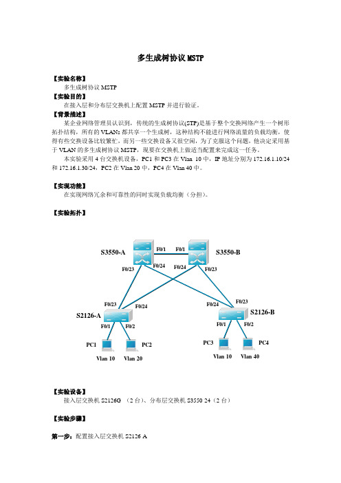
多生成树协议MSTP【实验名称】多生成树协议MSTP 【实验目的】在接入层和分布层交换机上配置MSTP 并进行验证。
【背景描述】某企业网络管理员认识到,传统的生成树协议(STP)是基于整个交换网络产生一个树形拓扑结构,所有的VLANs 都共享一个生成树,这种结构不能进行网络流量的负载均衡,使得有些交换设备比较繁忙,而另一些交换设备又很空闲,为了克服这个问题,他决定采用基于VLAN 的多生成树协议MSTP ,现要在交换机上做适当配置来完成这一任务。
本实验采用4台交换机设备,PC1和PC3在Vlan 10中,IP 地址分别为172.16.1.10/24和172.16.1.30/24,PC2在Vlan 20中,PC4在Vlan 40中。
【实现功能】 在实现网络冗余和可靠性的同时实现负载均衡(分担)。
【实验拓扑】Vlan 10Vlan 20Vlan 10Vlan 40F0/1F0/2F0/23F0/23F0/24F0/24F0/23F0/1F0/2【实验设备】 接入层交换机S2126G (2台)、分布层交换机S3550-24(2台)【实验步骤】第一步:配置接入层交换机S2126-AS2126-A (config)#spanning-tree !开启生成树S2126-A (config)#spanning-tree mode mstp !配置生成树模式为MSTPS2126-A(config)#vlan 10 !创建Vlan 10S2126-A(config)#vlan 20 !创建Vlan 20S2126-A(config)#vlan 40 !创建Vlan 40S2126-A(config)#interface fastethernet 0/1S2126-A(config-if)#switchport access vlan 10 !分配端口F0/1给Vlan 10S2126-A(config)#interface fastethernet 0/2S2126-A(config-if)#switchport access vlan 20 !分配端口F0/2给Vlan 20S2126-A(config)#interface fastethernet 0/23S2126-A(config-if)#switchport mode trunk !定义F0/23为trunk端口S2126-A(config)#interface fastethernet 0/24S2126-A(config-if)#switchport mode trunk !定义F0/24为trunk端口S2126-A(config)#spanning-tree mst configuration ! 进入MSTP配置模式S2126-A(config-mst)#instance 1 vlan 1,10 !配置instance 1(实例1)并关联Vlan 1和10 S2126-A(config-mst)#instance 2 vlan 20,40 !配置实例2并关联Vlan 20和40S2126-A(config-mst)#name region1 !配置域名称S2126-A(config-mst)#revision 1 !配置版本(修订号)验证测试:验证MSTP配置S2126-A#show spanning-tree mst configuration !显示MSTP全局配置Multi spanning tree protocol : EnabledName : region1Revision : 1Instance Vlans Mapped-------- ------------------------------------------------------------0 2-9,11-19,21- 39,41- 40941 1,102 20,40第二步:配置接入层交换机S2126-BS2126-B (config)#spanning-tree !开启生成树S2126-B (config)#spanning-tree mode mstp !采用MSTP生成树模式S2126-B(config)#vlan 10 !创建Vlan 10S2126-B(config)#vlan 20 !创建Vlan 20S2126-B(config)#vlan 40 !创建Vlan 40S2126-B(config)#interface fastethernet 0/1S2126-B(config-if)#switchport access vlan 10 !分配端口F0/1给Vlan 10S2126-B(config)#interface fastethernet 0/2S2126-B(config-if)#switchport access vlan 40 !分配端口F0/2给Vlan 40S2126-B(config)#interface fastethernet 0/23S2126-B(config-if)#switchport mode trunk !定义F0/23为trunk端口S2126-B(config)#interface fastethernet 0/24S2126-B(config-if)#switchport mode trunk !定义F0/24为trunk端口S2126-B(config)#spanning-tree mst configuration ! 进入MSTP配置模式S2126-B(config-mst)#instance 1 vlan 1,10 !配置instance 1(实例1)并关联Vlan 1和10 S2126-B(config-mst)#instance 2 vlan 20,40 !配置实例2并关联Vlan 20和40S2126-B(config-mst)#name region1 !配置域名称S2126-B(config-mst)#revision 1 !配置版本(修订号)验证测试:验证MSTP配置S2126-B#show spanning-tree mst configurationMulti spanning tree protocol : EnabledName : region1Revision : 1Instance Vlans Mapped-------- ------------------------------------------------------------0 2-9,11-19,21-39,41-40941 1,102 20,40第三步:配置分布层交换机S3550-AS3550-A(config)#spanning-tree !开启生成树S3550-A (config)#spanning-tree mode mstp !采用MSTP生成树模式S3550-A(config)#vlan 10S3550-A(config)#vlan 20S3550-A(config)#vlan 40S3550-A(config)#interface fastethernet 0/1S3550-A(config-if)#switchport mode trunk !定义F0/1为trunk端口S3550-A(config)#interface fastethernet 0/23S3550-A(config-if)#switchport mode trunk !定义F0/23为trunk端口S3550-A(config)#interface fastethernet 0/24S3550-A(config-if)#switchport mode trunk !定义F0/24为trunk端口S3550-A (config)#spanning-tree mst 1 priority 4096!配置交换机S3550-A在instance 1中的优先级为4096 ,缺省是32768,值越小越优先成为该instance中的root switchS3550-A (config)#spanning-tree mst configuration ! 进入MSTP配置模式S3550-A (config-mst)#instance 1 vlan 1,10 ! 配置实例1并关联Vlan 1和10S3550-A (config-mst)#instance 2 vlan 20,40 ! 配置实例2并关联Vlan 20和40S3550-A (config-mst)#name region1 ! 配置域名为region1S3550-A (config-mst)#revision 1 ! 配置版本(修订号)验证测试:验证MSTP配置S3550-A#show spanning-tree mst configurationMulti spanning tree protocol : EnabledName : region1Revision : 1Instance Vlans Mapped-------- ------------------------------------------------------------0 2-9,11-19,21-39,41-40941 1,102 20,40第四步:配置分布层交换机S3550-BS3550-B(config)#spanning-tree !开启生成树S3550-B (config)#spanning-tree mode mstp !采用MSTP生成树模式S3550-B(config)#vlan 10S3550-B(config)#vlan 20S3550-B(config)#vlan 40S3550-B(config)#interface fastethernet 0/1S3550-B(config-if)#switchport mode trunk ! 定义F0/1为trunk端口S3550-B(config)#interface fastethernet 0/23S3550-B(config-if)#switchport mode trunk ! 定义F0/23为trunk端口S3550-B(config)#interface fastethernet 0/24S3550-B(config-if)#switchport mode trunk ! 定义F0/24为trunk端口S3550-B (config)#spanning-tree mst 2 priority 4096 !配置交换机S3550-B在instance 2(实例2)中的优先级为4096 ,缺省是32768,值越小越优先成为该region (域)中的root switchS3550-B (config)#spanning-tree mst configuration ! 进入MSTP配置模式S3550-B (config-mst)#instance 1 vlan 1,10 ! 配置实例1并关联Vlan 1和10S3550-B (config-mst)#instance 2 vlan 20,40 ! 配置实例2并关联Vlan 20和40S3550-B (config-mst)#name region1 ! 配置域名为region1S3550-B (config-mst)#revision 1 ! 配置版本(修订号)验证测试:验证MSTP配置S3550-B#show spanning-tree mst configurationMulti spanning tree protocol : EnabledName : region1Revision : 1Instance Vlans Mapped-------- ------------------------------------------------------------0 2-9,11-19,21-39,41-40941 1,102 20,40第五步:验证交换机配置S3550-A#show spanning-tree mst 1 !显示交换机S3550-A上实例1的特性###### MST 1 vlans mapped : 1,10BridgeAddr : 00d0.f8ff.4e3f !交换机S3550-A的MAC地址Priority : 4096 ! 优先级TimeSinceTopologyChange : 0d:7h:21m:17sTopologyChanges : 0DesignatedRoot : 100100D0F8FF4E3F !后12位是MAC地址,此处显示是S3550-A自身的MAC,这说明S3550-A是实例1 (instance 1)的生成树的根交换机RootCost : 0RootPort : 0S3550-B#show spanning-tree mst 2 !显示交换机S3550-B上实例2的特性###### MST 2 vlans mapped : 20,40BridgeAddr : 00d0.f8ff.4662Priority : 4096TimeSinceTopologyChange : 0d:7h:31m:0sTopologyChanges : 0DesignatedRoot : 100200D0F8FF4662 ! S3550-B是实例2 (instance 2)的生成树的根交换机RootCost : 0RootPort : 0S2126-A#show spanning-tree mst 1 !显示交换机S2126-A上实例1的特性###### MST 1 vlans mapped : 1,10BridgeAddr : 00d0.f8fe.1e49Priority : 32768TimeSinceTopologyChange : 7d:3h:19m:31sTopologyChanges : 0DesignatedRoot : 100100D0F8FF4E3F ! 实例1的生成树的根交换机是S3550-A RootCost : 200000RootPort : Fa0/23 !对实例1而言,S2126-A的根端口是Fa0/23S2126-A#show spanning-tree mst 2 !显示交换机S2126-A上实例2的特性###### MST 2 vlans mapped : 20,40BridgeAddr : 00d0.f8fe.1e49Priority : 32768TimeSinceTopologyChange : 7d:3h:19m:31sTopologyChanges : 0DesignatedRoot : 100200D0F8FF4662 ! 实例2的生成树的根交换机是S3550-B RootCost : 200000RootPort : Fa0/24 !对实例2而言,S2126-A的根端口是Fa0/24类似可以验证其它交换机上的配置。
实验12 多生成树协议(MSTP)(V5.0)

实验12 多生成树协议(MSTP) (1)12.1 实验内容 (1)12.2 MSTP的基本配置 (1)12.2.1 实验目的 (1)12.2.2 实验组网图 (1)12.2.3 实验步骤 (2)12.3 MSTP的兼容配置 (12)12.3.1 实验目的 (12)12.3.2 实验组网图 (12)12.3.3 实验步骤 (12)实验12 多生成树协议(MSTP )12.1 实验内容MSTP 的基本配置MSTP 的兼容性配置12.2 MSTP 的基本配置12.2.1 实验目的掌握MSTP 的基本原理,包括ISTP 和CIST掌握MSTP 的基本概念熟悉MSTP 的基本配置12.2.2 实验组网图在本实验中,我们首先使用5台交换机来组建一个网络,其中三个构成LSWE LSWC LSWB LSWDE0/1E0/1E0/1E0/1E0/9E0/9E0/9E0/9E0/17E0/1712.2.3 实验步骤连接网络请根据如图0所示的网络进行网络连接。
当您完成网络连接并启动所有交换机后,您会发现什么样的现象。
是否发生了广播风暴?如果发生广播风暴,请您断开交换机A、B和C之间的任意一个连接,避免广播风暴的发生。
创建VLAN并指定端口到VLAN首先在所有的交换机上分别创建VLAN2、3、4,并为这些VLAN分配端口。
请按照要求执行如下配置命令:<Quidway>system-view[Quidway]sysname LSWA[LSWA]vlan 2[LSWA-vlan2]port Ethernet 0/2 to Ethernet 0/8[LSWA-vlan2]vlan 3[LSWA-vlan3]port Ethernet 0/10 to Ethernet 0/16[LSWA-vlan3]vlan 4[LSWA-vlan4]port Ethernet 0/18 to Ethernet 0/24[LSWA-vlan4]quit其它交换机的配置和交换机A类似,不再赘述。
简述MSTP与配置
简述MSTP与配置⼀、简介多⽣成树协议MSTP(Multiple Spanning Tree Protocol)是IEEE 802.1s中定义的⽣成树协议,通过⽣成多个⽣成树,来解决以太⽹环路问题。
MSTP的⽹络层次带外管理流量:管理平⾯和业务平⾯的数据是两根不同的线路带内管理流量:管理平⾯和业务平⾯的数据是同⼀根线路⼆、MSTP概述传统的⽣成树只运⾏⼀个实例,且收敛速度慢,RSTP在传统的STP基础上通过改进达到了加速⽹络拓扑收敛的⽬的,但是仍有缺陷,由于STP和RSTP在整个局域⽹中,所有VLAN共享⼀个⽣成树实例,因此⽆法实现基于VLAN的负载均衡,⽹络环境稳定状态下备份链路始终不能转发数据流量,造成带宽的浪费PVST-----它是思科私有的,多实例多WLAN可以实现负载均衡,但是他有缺陷⼀个实例只能p跑⼀个VLAN ,意味着100VLAN要开100个实例,它很吃资源的,所以是它的弊端MSTP-----多⽣成树协议。
⼀个实例当中,可以包含多个VLAN,它这个性能要⽐PVST性能好得多三、功能(1)具有TDM,以太以及ATM⽹络等多样业务的接⼊服务(2)包括TDM、以太⽹以及ATM⽹络等多样业务的传输服务包括P2P的⽹络传送功能(3)⽀持以太⽹与ATM的⽹络处理与复⽤功能(4)⽀持以太⽹和ATM业务,映射到SDH虚拟容器的功能四、配置命令1、stp mode mstp ###将交换机配置成MSTP模式2、Stp region-configuration ###创建stp区域设置3、Region-name huawei ###配置MSTP的区域名为huawei4、Revision-level 1 ###配置MSTP域的修订级别为15、Instance 1 vlan 10 ###将vlan 10加⼊实例1中6、Instance 2 vlan 20 ###将vlan 20加⼊实例2中7、active region-configuration ###激活MSTP域的配置8、Quit ###退出配置模式9、Stp instance 1 root primary ###配置交换机为实例1的主根桥10、Stp instance 2 root secondary ###配置此交换机为实例2的备份根桥11、Stp enable ###在所有的交换机上启⽤MSTP12、dis stp brief ###查看STP接⼝⾓⾊及状态信息。
锐捷多生成树协议MSTP配置

锐捷多生成树协议MSTP配置————————————————————————————————作者: ————————————————————————————————日期:多生成树协议MSTP【实验名称】多生成树协议MSTP【实验目的】在接入层和分布层交换机上配置MSTP并进行验证。
【背景描述】某企业网络管理员认识到,传统的生成树协议(STP)是基于整个交换网络产生一个树形拓扑结构,所有的VLANs都共享一个生成树,这种结构不能进行网络流量的负载均衡,使得有些交换设备比较繁忙,而另一些交换设备又很空闲,为了克服这个问题,他决定采用基于VLAN的多生成树协议MSTP,现要在交换机上做适当配置来完成这一任务。
本实验采用4台交换机设备,PC1和PC3在Vlan 10中,IP地址分别为172.16.1.10/24和172.16.1.30/24,PC2在Vlan20中,PC4在Vlan40中。
【实现功能】ﻩ在实现网络冗余和可靠性的同时实现负载均衡(分担)。
【实验拓扑】S3550-A S3550-BS2126-A S2126-BPC1PC2Vlan10Vlan20PC3PC4Vlan10Vlan40F0/1F0/2F0/23F0/24F0/23F0/24F0/24F0/23F0/23F0/24F0/1F0/1F0/1F0/2【实验设备】接入层交换机S2126G (2台)、分布层交换机S3550-24(2台)【实验步骤】第一步:配置接入层交换机S2126-AS2126-A (config)#spanning-tree!开启生成树S2126-A (config)#spanning-treemodemstp!配置生成树模式为MSTPS2126-A(config)#vlan 10 !创建Vlan 10S2126-A(config)#vlan 20!创建Vlan20S2126-A(config)#vlan 40!创建Vlan 40S2126-A(config)#interface fastethernet0/1S2126-A(config-if)#switchport access vlan10 !分配端口F0/1给Vlan10S2126-A(config)#interfacefastethernet0/2S2126-A(config-if)#switchport access vlan20 !分配端口F0/2给Vlan 20 S2126-A(config)#interfacefastethernet0/23S2126-A(config-if)#switchport modetrunk!定义F0/23为trunk端口S2126-A(config)#interface fastethernet 0/24S2126-A(config-if)#switchportmode trunk!定义F0/24为trunk端口S2126-A(config)#spanning-treemst configuration !进入MSTP配置模式S2126-A(config-mst)#instance 1vlan 1,10!配置instance1(实例1)并关联Vlan1和10S2126-A(config-mst)#instance 2 vlan 20,40 !配置实例2并关联Vlan 20和40S2126-A(config-mst)#nameregion1!配置域名称S2126-A(config-mst)#revision 1!配置版本(修订号)验证测试:验证MSTP配置S2126-A#show spanning-tree mst configuration! 显示MSTP全局配置Multi spanning tree protocol : EnabledName : region1Revision :1Instance Vlans Mapped-------- ------------------------------------------------------------02-9,11-19,21- 39,41- 40941 1,102 20,40第二步:配置接入层交换机S2126-BS2126-B(config)#spanning-tree!开启生成树S2126-B (config)#spanning-tree mode mstp !采用MSTP生成树模式S2126-B(config)#vlan10!创建Vlan 10S2126-B(config)#vlan 20 !创建Vlan 20S2126-B(config)#vlan 40!创建Vlan 40S2126-B(config)#interface fastethernet0/1S2126-B(config-if)#switchport access vlan 10 !分配端口F0/1给Vlan10 S2126-B(config)#interface fastethernet 0/2S2126-B(config-if)#switchport accessvlan40 !分配端口F0/2给Vlan40 S2126-B(config)#interfacefastethernet0/23S2126-B(config-if)#switchportmode trunk!定义F0/23为trunk端口S2126-B(config)#interface fastethernet 0/24S2126-B(config-if)#switchportmode trunk !定义F0/24为trunk端口S2126-B(config)#spanning-tree mstconfiguration ! 进入MSTP配置模式S2126-B(config-mst)#instance1vlan 1,10!配置instance1(实例1)并关联Vlan1和10S2126-B(config-mst)#instance2 vlan20,40 !配置实例2并关联Vlan 20和40S2126-B(config-mst)#name region1 !配置域名称S2126-B(config-mst)#revision 1!配置版本(修订号)验证测试:验证MSTP配置S2126-B#show spanning-treemst configurationMulti spanning tree protocol: EnabledName:region1Revision: 1InstanceVlansMapped--------------------------------------------------------------------0 2-9,11-19,21-39,41-40941 1,102 20,40第三步:配置分布层交换机S3550-AS3550-A(config)#spanning-tree !开启生成树S3550-A(config)#spanning-tree modemstp!采用MSTP生成树模式S3550-A(config)#vlan 10S3550-A(config)#vlan20S3550-A(config)#vlan 40S3550-A(config)#interface fastethernet 0/1S3550-A(config-if)#switchport modetrunk!定义F0/1为trunk端口S3550-A(config)#interfacefastethernet 0/23S3550-A(config-if)#switchport mode trunk!定义F0/23为trunk端口S3550-A(config)#interfacefastethernet 0/24S3550-A(config-if)#switchport modetrunk !定义F0/24为trunk端口S3550-A(config)#spanning-tree mst 1 priority4096!配置交换机S3550-A在instance1中的优先级为4096,缺省是32768,值越小越优先成为该instance中的rootswitchS3550-A (config)#spanning-tree mst configuration !进入MSTP配置模式S3550-A(config-mst)#instance1vlan1,10 ! 配置实例1并关联Vlan 1和10S3550-A(config-mst)#instance 2vlan20,40 !配置实例2并关联Vl an 20和40S3550-A(config-mst)#name region1 !配置域名为region1S3550-A (config-mst)#revision1! 配置版本(修订号)验证测试:验证MSTP配置S3550-A#show spanning-treemst configurationMulti spanningtreeprotocol: EnabledName:region1Revision:1Instance Vlans Mapped-------- ------------------------------------------------------------02-9,11-19,21-39,41-40941 1,102 20,40第四步:配置分布层交换机S3550-BS3550-B(config)#spanning-tree !开启生成树S3550-B (config)#spanning-treemode mstp!采用MSTP生成树模式S3550-B(config)#vlan 10S3550-B(config)#vlan 20S3550-B(config)#vlan40S3550-B(config)#interfacefastethernet 0/1S3550-B(config-if)#switchport mode trunk!定义F0/1为trunk端口S3550-B(config)#interface fastethernet 0/23S3550-B(config-if)#switchport mode trunk! 定义F0/23为trunk端口S3550-B(config)#interface fastethernet 0/24S3550-B(config-if)#switchportmodetrunk! 定义F0/24为trunk端口S3550-B(config)#spanning-tree mst2priority4096 !配置交换机S3550-B在instance2(实例2)中的优先级为4096 ,缺省是32768,值越小越优先成为该region (域)中的root switchS3550-B (config)#spanning-treemst configuration !进入MSTP配置模式S3550-B (config-mst)#instance1vlan 1,10!配置实例1并关联Vlan 1和10S3550-B(config-mst)#instance 2 vlan 20,40 ! 配置实例2并关联Vlan 20和40S3550-B (config-mst)#nameregion1 !配置域名为region1S3550-B(config-mst)#revision 1 ! 配置版本(修订号)验证测试:验证MSTP配置S3550-B#showspanning-tree mst configurationMulti spanning tree protocol:EnabledName: region1Revision: 1Instance VlansMapped-------- ------------------------------------------------------------0 2-9,11-19,21-39,41-409411,102 20,40第五步:验证交换机配置S3550-A#show spanning-tree mst 1!显示交换机S3550-A上实例1的特性######MST 1 vlansmapped:1,10BridgeAddr :00d0.f8ff.4e3f!交换机S3550-A的MAC 地址Priority : 4096 ! 优先级TimeSinceTopologyChange: 0d:7h:21m:17sTopologyChanges:0DesignatedRoot : 100100D0F8FF4E3F!后12位是MAC地址,此处显示是S3550-A自身的MAC,这说明S3550-A是实例1 (instance1)的生成树的根交换机RootCost: 0RootPort: 0S3550-B#showspanning-tree mst 2 !显示交换机S3550-B上实例2的特性###### MST2 vlans mapped: 20,40BridgeAddr: 00d0.f8ff.4662Priority : 4096TimeSinceTopologyChange: 0d:7h:31m:0sTopologyChanges :0DesignatedRoot:100200D0F8FF4662!S3550-B是实例2(instance 2)的生成树的根交换机RootCost : 0RootPort :0S2126-A#showspanning-treemst 1!显示交换机S2126-A上实例1的特性###### MST 1 vlans mapped :1,10BridgeAddr :00d0.f8fe.1e49Priority : 32768TimeSinceTopologyChange: 7d:3h:19m:31sTopologyChanges :0DesignatedRoot :100100D0F8FF4E3F !实例1的生成树的根交换机是S3550-ARootCost :200000RootPort : Fa0/23!对实例1而言,S2126-A的根端口是Fa0/23S2126-A#show spanning-treemst2!显示交换机S2126-A上实例2的特性###### MST 2 vlansmapped : 20,40BridgeAddr:00d0.f8fe.1e49Priority: 32768TimeSinceTopologyChange:7d:3h:19m:31sTopologyChanges: 0DesignatedRoot : 100200D0F8FF4662 !实例2的生成树的根交换机是S3550-BRootCost :200000RootPort: Fa0/24 !对实例2而言,S2126-A的根端口是Fa0/24类似可以验证其它交换机上的配置。
mstp协议简介
mstp协议简介一、引言MSTP(Multiple Spanning Tree Protocol,多重生成树协议)是一种用于构建和维护网络中的多个生成树的协议。
它是基于IEEE 802.1Q标准的一种扩展,旨在提供更高的网络可靠性和冗余。
二、背景在传统的生成树协议(如STP)中,只能构建一棵生成树来确保网络中没有环路,并且只有一条路径可用,其他路径被阻塞。
这种方法在网络规模较小的情况下是有效的,但在大型网络中,可能会导致链路资源的浪费和网络性能的降低。
三、MSTP的工作原理MSTP通过将网络划分为多个实例(也称为VLAN)来解决传统生成树协议的限制。
每个实例都有一个独立的生成树,并且可以在不同的实例之间共享链路资源。
MSTP使用了一种称为CIST(Common and Internal Spanning Tree,公共和内部生成树)的结构,其中CIST是所有实例共享的生成树,而每个实例都有自己的生成树。
MSTP的工作流程如下:1. 桥交换机收集网络中所有桥交换机的信息,并计算生成树。
2. 桥交换机之间通过BPDU(Bridge Protocol Data Unit,桥协议数据单元)交换信息,以确定生成树的拓扑结构。
3. 桥交换机根据接收到的BPDU信息,选择最佳路径,并阻塞其他冗余路径,从而构建生成树。
四、MSTP的优势1. 提供更高的网络可靠性:MSTP允许在网络中构建多个生成树,从而提供了冗余路径。
当某个路径发生故障时,MSTP可以快速切换到备用路径,从而确保网络的可用性。
2. 提高网络性能:MSTP允许在网络中共享链路资源,避免了传统生成树协议中的资源浪费问题。
这样可以更好地利用网络带宽,提高网络的吞吐量和响应速度。
3. 简化网络管理:MSTP通过将网络划分为多个实例,使得网络管理更加灵活和可控。
管理员可以根据网络的需求,为不同的实例分配不同的优先级和资源,从而实现更精细的网络管理。
五、MSTP的应用场景MSTP广泛应用于大型企业网络和数据中心等场景,特别适用于需要高可用性和强冗余的网络环境。
rstp和mstp配置实验原理
rstp和mstp配置实验原理RSTP和MSTP都是生成树协议,分别对应于局域网和城域网。
它们的主要区别在于RSTP是STP的改进型,而MSTP则兼容STP和RSTP,并通过对多个实例的生成树的运行来实现业务流量和用户流量的隔离,以及在数据转发过程中实现VLAN数据的负载均衡。
RSTP的配置实验原理如下:1.RSTP的运作方式与STP类似,但在运作方式上有所改进。
它通过比较每个交换机的BID来选举根交换机,BID越小越好。
2.RSTP的端口角色选举规则是首先比较端口到根交换机的开销,越小越好;开销一样,比较端口所在的交换机的BID,越小越好;若BID一样,比较端口的PID,越小越好。
3.在RSTP中,每个非根交换机上,有且只有一个距离根交换机最近的端口;每个链路上,有且只有一个距离根网桥最近的端口。
4.RSTP通过阻塞一些端口来逻辑上断开环路,防止广播风暴的产生。
当主线路故障时,阻塞接口被激活;主线路恢复时,备份线路再次阻塞。
而MSTP的配置实验原理如下:1.MSTP通过多实例能实现对业务流量和用户流量的隔离,同时还提供了数据转发的多个冗余路径。
在MSTP中,可以将若干个VLAN映射到一个实例(instance),MSTP将为每个instance运行一颗生成树。
2.MSTP可以基于instance设置优先级、端口路径开销等参数。
3.MSTP将VLAN根据不同的划分位集中实例,每个实例对应不同的生成树,所以可以实现数据流量的负载均衡,同时也解决了因VLAN过多而引起的资源占用过大的问题。
总的来说,RSTP和MSTP都是为了解决网络中的环路问题,通过阻塞一些端口来防止广播风暴的产生。
同时,MSTP还通过将不同的VLAN映射到不同的实例中,实现了数据流量的负载均衡和资源的有效利用。
任务2.9 多生成树协议MSTP配置

配置ØSTP/RSTP弊端Ø多生成树协议MSTPØMST域配置ØMSTI拓扑设计ØMSTP配置流程ØMSTP配置命令•在STP/RSTP环境下只能构造一棵生成树,即网络中所有VLAN共用这一棵树。
正常情况下,所有流量都沿主链路传输,而备份链路将一直处于空闲状态,线路资源没有充分利用。
•多生成树协议MSTP可以基于不同实例构造出不同的生成树,基于合理的规划设计,可实现数据流量的负载分担,提高网络的通信效率。
•本次任务介绍MSTP的基本原理和配置方法。
Ø网络中存在多个VLAN时,基于STP/RSTP协议运算只能构造一棵生成树,所有VLAN的主备链路一致,流量都通过主链路通信,备份链路始终处于空闲状态。
Ø多生成树协议MSTP可以基于实例(VLAN分组)构建不同的生成树,使不同VLAN的流量沿不同路径转发,实现数据流量的负载分担。
ØMSTP可实现设备在不同实例中对应不同的主备状态,从而使通信线路互为备份,提高网络的容错能力。
STP/RSTP单生成树MSTP多生成树(1)MSTP基本概念ØMSTP把一个交换网络划分成1个或多个MST域(Multiple Spanning TreeRegion),每个MST域内生成1棵或多棵生成树,生成树之间彼此独立。
每棵生成树叫做一个多生成树实例MSTI。
每个MSTI都使用单独的RSTP算法。
MSTP网络层次结构(1)MSTP术语ØMST域:由多台交换设备以及它们之间的网段所构成。
ØMSTI:MST域内的生成树实例,每个实例对应一棵生成树。
ØCST:连接所有MST域的一棵生成树。
ØIST:各MST域内实例ID为0的一棵生成树,通常称为MSTI0。
公共生成树CST(1)MSTP术语ØCIST:连接一个交换网络内所有交换设备的单生成树。
mstp报文详解
mstp报文详解MSTP(Multiple Spanning Tree Protocol,多重生成树协议)是一种用于构建和维护网络中多个生成树的协议。
它是基于IEEE 802.1Q标准的生成树协议的扩展,可以在一个网络中支持多个VLAN,并为每个VLAN构建独立的生成树。
本文将详细解析MSTP报文的结构和功能。
MSTP报文主要分为配置报文和通告报文两种类型。
配置报文用于配置生成树的参数,而通告报文用于交换生成树的拓扑信息。
配置报文包括配置BPDU(Bridge Protocol Data Unit,桥协议数据单元)和配置消息。
配置BPDU是用于交换生成树的根桥、桥优先级、端口优先级等信息的报文。
配置消息则是用于交换生成树的配置信息,包括生成树实例的标识、生成树的根桥、生成树的桥优先级等。
通告报文包括通告BPDU和通告消息。
通告BPDU是用于交换生成树的拓扑信息的报文,包括生成树的根桥、桥优先级、端口优先级等。
通告消息则是用于交换生成树的拓扑信息,包括生成树实例的标识、生成树的根桥、生成树的桥优先级等。
MSTP报文的结构如下:1. 首部:包括协议标识、版本号等信息。
2. 配置报文:包括配置BPDU和配置消息。
- 配置BPDU:包括根桥ID、桥优先级、端口优先级等信息。
- 配置消息:包括生成树实例的标识、根桥ID、桥优先级等信息。
3. 通告报文:包括通告BPDU和通告消息。
- 通告BPDU:包括根桥ID、桥优先级、端口优先级等信息。
- 通告消息:包括生成树实例的标识、根桥ID、桥优先级等信息。
MSTP报文的功能如下:1. 生成树计算:MSTP报文用于计算生成树的拓扑结构,确定每个生成树的根桥、桥优先级、端口优先级等参数。
2. 生成树维护:MSTP报文用于维护生成树的状态,包括生成树的根桥、桥优先级、端口优先级等信息。
3. 生成树更新:MSTP报文用于更新生成树的拓扑结构,当网络中发生拓扑变化时,MSTP报文可以及时更新生成树的状态。
多生成树协议mstp的作用_概述及解释说明
多生成树协议mstp的作用概述及解释说明1. 引言1.1 概述在现代网络通信中,生成树协议(Spanning Tree Protocol, STP)被广泛应用以确保网络拓扑的冗余和可靠性。
然而,传统STP的局限性导致了一些问题,例如对于大型网络来说,单个生成树的构建和管理十分困难,带宽利用率低下等。
为了克服这些问题,多生成树协议(Multiple Spanning Tree Protocol, MSTP)被引入并逐渐成为网络领域关注的热点。
本文将对MSTP的作用进行全面概述及解释说明,并探讨其在实际应用中的优势和应用场景。
1.2 文章结构本文主要分为五个部分:引言、多生成树协议MSTP的作用、MSTP概述及基本原理、MSTP实践案例分析以及结论与展望。
引言部分旨在介绍本文的整体内容架构以及MSTP在网络通信中的重要性。
接下来将详细介绍多生成树协议MSTP的定义、特点以及与传统生成树协议相比的优势。
随后会对MSTP进行详细概述,并阐述其基本原理、工作步骤以及关键技术与算法等内容。
在MSTP的基础上,通过实践案例分析将展示MSTP在不同网络环境中的应用情况和效果。
最后,我们将对全文进行总结,并对多生成树协议的未来发展前景进行展望。
1.3 目的本文的目的是为读者提供一个全面深入理解多生成树协议MSTP的作用,并探讨其在实际应用中的优势和应用场景。
通过介绍MSTP的概念、原理和关键技术,希望读者能够了解到MSTP如何解决传统STP存在的问题,并且能够在实际网络构建和管理中灵活应用MSTP,提高网络拓扑可靠性和性能。
同时,通过案例分析可以让读者更加直观地了解MSTP在不同场景下的具体应用效果。
最后,本文也将对多生成树协议未来发展前景进行一些展望。
2. 多生成树协议MSTP的作用2.1 MSTP简介多生成树协议(Multiple Spanning Tree Protocol,简称MSTP)是一种用于构建冗余网络拓扑的协议。
RSTP及MSTP配置教程

RSTP及MSTP配置教程•引言•RSTP配置基础•MSTP配置基础•RSTP与MSTP比较目录•RSTP与MSTP配置实例•配置优化与故障排除•总结与展望01引言目的和背景满足网络需求随着企业网络的日益复杂,对网络的可靠性和性能要求也越来越高。
RSTP(快速生成树协议)和MSTP(多生成树协议)作为网络协议,能够提高网络的稳定性和性能,满足企业不断增长的网络需求。
提高网络可靠性RSTP和MSTP通过消除网络中的环路,避免了广播风暴和资源浪费,从而提高了网络的可靠性。
优化网络性能通过合理配置RSTP和MSTP,可以优化网络性能,减少网络拥塞和延迟,提高数据传输效率。
基本概念介绍配置步骤详解配置实例分析故障排除与优化建议教程范围本教程将首先介绍RSTP和MSTP 的基本概念、工作原理和优势。
通过具体的配置实例,分析RSTP和MSTP在实际网络环境中的应用和效果。
详细阐述如何在网络设备(如交换机、路由器等)上配置RSTP 和MSTP,包括具体的配置命令和步骤。
提供RSTP和MSTP配置过程中可能出现的故障排除方法,以及针对网络性能优化的建议。
02 RSTP配置基础RSTP(Rapid Spanning Tree Protocol)即快速生成树协议,是一种网络协议,该协议可应用于在网络中建立树形拓扑,消除二层环路,并且在网络结构发生变化时,能迅速的恢复网络的连通性。
RSTP相比STP(Spanning Tree Protocol),在网络结构发生变化时,能更快的收敛网络,恢复网络的连通性,提高了网络的稳定性和可用性。
RSTP概述VS配置前准备确定网络拓扑结构在进行RSTP配置之前,需要明确网络的拓扑结构,包括网络中的设备、链路以及设备的连接关系等。
选择根桥和备份根桥在配置RSTP时,需要选择网络中的一台设备作为根桥,其他设备作为非根桥。
同时,为了提高网络的可靠性,还需要选择一台设备作为备份根桥。
确定端口角色根据网络拓扑和设备连接关系,确定每个设备上端口的角色,包括根端口、指定端口、替代端口和备份端口等。
MSTP是一个多生成树协议
MSTP是一个多生成树协议。
MSTP的“多生成树”包括两层含义:一是在一个交换网络中可以基于VLAN划分出多个生成树实例(STI),二是在每个生成树实例中可以包括多个VLAN。
而不是像Cisco的PVST、PVST+这样,虽然在整个交换网络中可以基于VLAN划分出多个生成树实例,但是每个生成树实例中仅包括一个VLAN。
所以相对PVST、PVST+来说,MSTP更适用于比较大的网络中,划分生成树实例也更灵活,可以根据实际应用需要求来进行。
虽然在整体来看,MSTP网络可分为以下层次(如图21-1所示):●MSTP网络●多生成树域MST Region(MultipleSpanning Tree Region)●多生成树实例MSTI(Multiple SpanningTree Instance)图21-1MSTP的网络层次示意图而且这三者之间依次是包含关系,即MSTP网络包含MST域和MSTI,MST 域又包含MSTI,因为在一个MSTP网络中可以有多个MST域,一个MST域中又可以有多个MSTI。
1.MST域MST域(Multiple Spanning Tree Regions,多生成树域)是由交换网络中的多台交换机以及它们之间的网段构成(在Cisco中是叫“MST区域”)。
这些交换机都启动了MSTP、具有相同的域名、相同的VLAN到生成树映射(是一个描述了VLAN和MSTI之间映射关系的映射表)配置和相同的MSTP修订级别配置,并且物理上有链路连通。
一个局域网中可以存在多个MST域,各MST域之间在物理上直接或间接相连。
用户可以通过MSTP配置命令把多台交换机划分在同一个MST域内。
在如图21-1所示的MSTP网络中有三个MST域(MST域1、MST域2和MST域3),域内所有交换机(图中每个生成树实例中的每个小圆圈代表一台交换机)都有相同的MST域配置。
2.MSTIMSTI(Multiple Spanning Tree Instance,多生成树实例)是指MST域内的生成树。
mstp协议简介

mstp协议简介MSTP(Multiple Spanning Tree Protocol)是一种用于构建冗余网络的协议,它基于IEEE 802.1s标准。
MSTP协议允许网络管理员在一个网络中同时运行多个生成树,从而提供更高的网络可靠性和冗余。
本文将详细介绍MSTP协议的工作原理、配置和优势。
一、MSTP协议的工作原理MSTP协议通过将网络划分为不同的区域(也称为MST实例)来实现多个生成树的运行。
每个MST实例都有一个唯一的实例标识符(Instance Identifier),用于区分不同的生成树。
MSTP协议使用配置桥(Configuration Bridge)来管理生成树,并通过生成树协调器(Tree Coordinator)来协调不同生成树之间的信息交换。
MSTP协议的工作过程如下:1. 桥优先级选举:在每个MST实例中,桥优先级最低的桥将被选举为根桥(Root Bridge),其他桥将成为根桥的子桥(Root Port)或非根桥(Designated Bridge)。
2. 端口角色选择:每个桥的端口将被分配为根端口(Root Port)、指定端口(Designated Port)或非指定端口(Non-Designated Port)。
3. 生成树计算:MSTP协议使用生成树计算算法,计算出每个MST实例的生成树路径。
4. BPDU交换:桥通过交换BPDU(Bridge Protocol Data Unit)来传递生成树信息,包括根桥、端口角色和生成树路径等。
5. 网络收敛:当网络中发生链路故障或拓扑变化时,MSTP协议能够快速收敛,并重新计算生成树路径,确保网络的可用性。
二、MSTP协议的配置MSTP协议的配置包括以下几个重要的步骤:1. 设定实例标识符:每个MST实例都需要有唯一的实例标识符。
网络管理员需要为每个MST实例分配一个实例标识符,并确保各个桥之间的实例标识符一致。
2. 桥优先级设置:网络管理员可以手动设置每个桥的优先级,以决定根桥的选举结果。
- 1、下载文档前请自行甄别文档内容的完整性,平台不提供额外的编辑、内容补充、找答案等附加服务。
- 2、"仅部分预览"的文档,不可在线预览部分如存在完整性等问题,可反馈申请退款(可完整预览的文档不适用该条件!)。
- 3、如文档侵犯您的权益,请联系客服反馈,我们会尽快为您处理(人工客服工作时间:9:00-18:30)。
实验六:多生成树协议MSTP 的配置实验目的了解并掌握多生成树协议的配置 背景描述某企业网络管理员认识到,传统的生成树协议(STP)是基于整个交换网络产生一个树形拓扑结构,所有的VLANs 都共享一个生成树,这种结构不能进行网络流量的负载均衡,使得有些交换设备比较繁忙,而另一些交换设备又很空闲,为了克服这个问题,他决定采用基于VLAN 的多生成树协议MSTP ,现要在交换机上做适当配置来完成这一任务。
实验拓扑完整实验拓扑图实例1的生成树拓扑图实例2的生成树拓扑图 Switch1 Switch4 Switch3 Fa0/3 Fa0/4Fa0/1 Fa0/2 BridgeAddr :00d0.f8b8.dc8eBridgeAddr :00d0.f8bc.9b33 BridgeAddr :00d0.f8bc.9a8f Switch2 Switch4Switch3Fa0/4 Fa0/3Fa0/2Fa0/1 BridgeAddr :00d0.f8b8.1bf8BridgeAddr :00d0.f8bc.9b33 BridgeAddr :00d0.f8bc.9a8fSwitch1 Switch2 Switch4 Switch3Fa0/1 Fa0/2 Fa0/2 Fa0/1 Fa0/4 Fa0/3 Fa0/2 Fa0/2 Fa0/1 Fa0/3 Fa0/4 Fa0/1实验步骤1.交换机Switch1的一些相应配置(1)创建Vlan10和Vlan20Switch1(config)#vlan 10Switch1(config-vlan)#exitSwitch1(config)#vlan 20Switch1(config-vlan)#exit(2)设置Trunk口和端口fa0/1与fa0/2的聚合Switch1(config)#inter range fa 0/1-2Switch1(config-if-range)#switchport mode trunkSwitch1(config-if-range)#exitSwitch1(config)#inter range fa 0/1-2Switch1(config-if-range)#port-group 1Switch1(config-if-range)#exit !设置端口fa0/1-2为trunk并端口聚合Switch1(config)#inter range fa 0/3-4Switch1(config-if-range)#switchport mode trunkSwitch1(config-if-range)#exit(3)开启生成树协议设为MSTP模式,并作相应设置Switch1(config)#spanning-tree!开启生成树Switch1(config)#spanning-tree mode mstp!配置生成树模式为MSTPSwitch1(config)#spanning-tree mst configuration! 进入MSTP配置模式Switch1(config-mst)#name taishan!配置域名称Switch1(config-mst)#revision 1!配置版本(修订号)Switch1(config-mst)#instance 1 vlan 10!配置instance 1(实例1)并关联Vlan 10 Switch1(config-mst)#instance 2 vlan 20!配置instance 2(实例2)并关联Vlan 20 Switch1(config-mst)#exitSwitch1(config)#spanning-tree mst 1 priority 8192!提升交换机Switch1在实例1上的优先级,缺省是32768,值越小越优先成为该instance 中的root switch,这一配置能确定Switch1为instance的根桥Switch1(config)#end【注意事项】l 对规模很大的交换网络可以划分多个域(region),在每个域里可以创建多个instance(实例);2 划分在同一个域里的各台交换机须配置相同的域名(name)、相同的修订号(revision number)、相同的instance—vlan 对应表;3 交换机可以支持65个MSTP instance,其中实例0是缺省实例,是强制存在的,其它实例可以创建和删除;4 将整个spanning-tree恢复为缺省状态用命令spanning-tree reset 。
5 注意各个交换机的查看(验证)配置信息应该在所有的交换机配置完成后进行。
验证配置:(1)显示MSTP全局配置Switch1#show spanning-tree mst configuration!显示MSTP全局配置Multi spanning tree protocol : EnabledName : taishanRevision : 1Instance Vlans Mapped-------- ------------------------------------------------------------0 1-9,11-19,21-40941 102 20(2)查看生成树信息Switch1#show spanning-tree!查看生成树信息StpVersion : MSTPSysStpStatus : EnabledBaseNumPorts : 24MaxAge : 20HelloTime : 2ForwardDelay : 15BridgeMaxAge : 20BridgeHelloTime : 2BridgeForwardDelay : 15MaxHops : 20TxHoldCount : 3PathCostMethod : LongBPDUGuard : DisabledBPDUFilter : Disabled###### MST 1 vlans mapped : 10 !instance1的配置信息BridgeAddr : 00d0.f8b8.dc8ePriority : 8192TimeSinceTopologyChange : 0d:0h:43m:39sTopologyChanges : 0DesignatedRoot : 200100D0F8B8DC8E!后12位是MAC地址,此处显示是Switch1自身的MAC,这说明Switch1是实例1 (instance 1)的生成树的根交换机RootCost : 0RootPort : 0Switch1#show spanning-tree interface fa 0/1PortAdminPortfast : DisabledPortOperPortfast : DisabledPortAdminLinkType : autoPortOperLinkType : point-to-pointPortBPDUGuard: DisabledPortBPDUFilter: Disabled###### MST 1 vlans mapped : 10PortState : discardingPortPriority : 128PortDesignatedRoot : 800100D0F8B81BF8PortDesignatedCost : 0PortDesignatedBridge : 800100D0F8B81BF8PortDesignatedPort : 0000PortForwardTransitions : 0PortAdminPathCost : 0PortOperPathCost : 0PortRole : disabledPort###### MST 2 vlans mapped : 20PortState : discardingPortPriority : 128PortDesignatedRoot : 800200D0F8B81BF8PortDesignatedCost : 0PortDesignatedBridge : 800200D0F8B81BF8PortDesignatedPort : 0000PortForwardTransitions : 0PortAdminPathCost : 0PortOperPathCost : 0PortRole : disabledPort!接口fa0/1在实例1和2上的状态均为disabledPort###### MST 2 vlans mapped : 20 !instanc2的配置信息BridgeAddr : 00d0.f8b8.dc8ePriority : 32768TimeSinceTopologyChange : 0d:0h:43m:39sTopologyChanges : 0DesignatedRoot : 200200D0F8B81BF8!此处显示是Switch2的MAC,这说明Switch12是实例2 (instance 2)的生成树的根交换机RootCost : 190000RootPort : Ag1Switch1#show spanning-tree interface fa 0/2PortAdminPortfast : DisabledPortOperPortfast : DisabledPortAdminLinkType : autoPortOperLinkType : point-to-point PortBPDUGuard: DisabledPortBPDUFilter: Disabled###### MST 1 vlans mapped : 10PortState : discardingPortPriority : 128PortDesignatedRoot : 800100D0F8B81BF8 PortDesignatedCost : 0PortDesignatedBridge : 800100D0F8B81BF8 PortDesignatedPort : 0000 PortForwardTransitions : 0PortAdminPathCost : 0PortOperPathCost : 0PortRole : disabledPort###### MST 2 vlans mapped : 20PortState : discardingPortPriority : 128PortDesignatedRoot : 800200D0F8B81BF8 PortDesignatedCost : 0PortDesignatedBridge : 800200D0F8B81BF8 PortDesignatedPort : 0000 PortForwardTransitions : 0PortAdminPathCost : 0PortOperPathCost : 0PortRole : disabledPort!接口fa0/2在实例1和2上的状态均为disabledPort(5)查看接口fa0/3的生成树信息Switch1#show spanning-tree interface fa 0/3PortAdminPortfast : DisabledPortOperPortfast : DisabledPortAdminLinkType : autoPortOperLinkType : point-to-pointPortBPDUGuard: DisabledPortBPDUFilter: Disabled###### MST 1 vlans mapped : 10PortState : forwardingPortPriority : 128PortDesignatedRoot : 200100D0F8B8DC8E PortDesignatedCost : 190000PortDesignatedBridge : 800100D0F8B81BF8 PortDesignatedPort : 8003PortForwardTransitions : 1PortAdminPathCost : 0PortOperPathCost : 200000PortRole : designatedPort !fa0/3为实例1的指定端口###### MST 2 vlans mapped : 20PortState : forwardingPortPriority : 128PortDesignatedRoot : 200200D0F8B81BF8 PortDesignatedCost : 0PortDesignatedBridge : 200200D0F8B81BF8 PortDesignatedPort : 8003PortForwardTransitions : 1PortAdminPathCost : 0PortOperPathCost : 200000PortRole : designatedPort !fa0/3为实例2的指定端口(6)查看接口fa0/4的生成树信息Switch1#show spanning-tree interface fa 0/4PortAdminPortfast : DisabledPortOperPortfast : DisabledPortAdminLinkType : autoPortOperLinkType : point-to-pointPortBPDUGuard: DisabledPortBPDUFilter: Disabled###### MST 1 vlans mapped : 10PortState : forwardingPortPriority : 128PortDesignatedRoot : 200100D0F8B8DC8E PortDesignatedCost : 190000PortDesignatedBridge : 800100D0F8B81BF8 PortDesignatedPort : 8004PortForwardTransitions : 1PortAdminPathCost : 0PortOperPathCost : 200000PortRole : designatedPort !fa0/4为实例1的指定端口###### MST 2 vlans mapped : 20PortState : forwardingPortPriority : 128PortDesignatedRoot : 200200D0F8B81BF8 PortDesignatedCost : 0PortDesignatedBridge : 200200D0F8B81BF8 PortDesignatedPort : 8004PortForwardTransitions : 1PortAdminPathCost : 0PortOperPathCost : 200000PortRole : designatedPort !fa0/4为实例2的指定端口2.交换机Switch2的一些相应配置(1)创建Vlan10和Vlan20Switch2(config)#vlan 10Switch2(config-vlan)#exitSwitch2(config)#vlan 20Switch2(config-vlan)#exit(2)设置Trunk口和端口fa0/1与fa0/2的聚合Switch2(config)#inter range fa 0/1-2Switch2(config-if-range)#switchport mode trunkSwitch2(config-if-range)#exitSwitch2(config)#inter range fa 0/1-2Switch2(config-if-range)#port-group 1Switch2(config-if-range)#exitSwitch2(config)#inter range fa 0/3-4Switch2(config-if-range)#switchport mode trunkSwitch2(config-if-range)#exit(3)开启生成树协议设为MSTP模式,并作相应设置Switch2(config)#spanning-treeSwitch2(config)#spanning-tree mode mstpSwitch2(config)#spanning-tree mst configurationSwitch2(config-mst)#name taishanSwitch2(config-mst)#revision 1Switch2(config-mst)#instance 1 vlan 10Switch2(config-mst)#instance 2 vlan 20Switch2(config-mst)#exitSwitch2(config)#spanning-tree mst 2 priority 8192!提升交换机Switch1在实例1上的优先级,这一配置能确定Switch1为instance的根桥Switch2(config)#end验证配置:(1)显示MSTP全局配置Switch2#show spanning-tree mst configurationMulti spanning tree protocol : EnabledName : taishanRevision : 1Instance Vlans Mapped-------- ------------------------------------------------------------0 1-9,11-19,21-40941 102 20(2)查看生成树信息Switch2#show spanning-treeStpVersion : MSTPSysStpStatus : EnabledBaseNumPorts : 24MaxAge : 20HelloTime : 2ForwardDelay : 15BridgeMaxAge : 20BridgeHelloTime : 2BridgeForwardDelay : 15MaxHops : 20TxHoldCount : 3PathCostMethod : LongBPDUGuard : DisabledBPDUFilter : Disabled###### MST 1 vlans mapped : 10BridgeAddr : 00d0.f8b8.1bf8Priority : 32768TimeSinceTopologyChange : 0d:1h:4m:54sTopologyChanges : 0DesignatedRoot : 200100D0F8B8DC8E!此处显示是Switch1的MAC,这说明Switch1是实例1 (instance 1)的生成树的根交换机RootCost : 190000RootPort : Ag1###### MST 2 vlans mapped : 20BridgeAddr : 00d0.f8b8.1bf8Priority : 8192TimeSinceTopologyChange : 0d:1h:4m:54sTopologyChanges : 0DesignatedRoot : 200200D0F8B81BF8!此处显示是Switch2的自身MAC,这说明Switch2是实例2 (instance 2)的生成树的根交换机RootCost : 0RootPort : 0(3)查看接口fa0/1的生成树信息Switch2#show spanning-tree interface fa 0/1PortAdminPortfast : Disabled PortOperPortfast : Disabled PortAdminLinkType : auto PortOperLinkType : point-to-point PortBPDUGuard: Disabled PortBPDUFilter: Disabled###### MST 1 vlans mapped : 10 PortState : discardingPortPriority : 128PortDesignatedRoot : 800100D0F8B81BF8 PortDesignatedCost : 0 PortDesignatedBridge : 800100D0F8B81BF8 PortDesignatedPort : 0000 PortForwardTransitions : 0 PortAdminPathCost : 0 PortOperPathCost : 0PortRole : disabledPort###### MST 2 vlans mapped : 20 PortState : discardingPortPriority : 128PortDesignatedRoot : 800200D0F8B81BF8 PortDesignatedCost : 0 PortDesignatedBridge : 800200D0F8B81BF8 PortDesignatedPort : 0000 PortForwardTransitions : 0 PortAdminPathCost : 0 PortOperPathCost : 0PortRole : disabledPortSwitch2#show spanning-tree interface fa 0/2 PortAdminPortfast : Disabled PortOperPortfast : Disabled PortAdminLinkType : auto PortOperLinkType : point-to-point PortBPDUGuard: Disabled PortBPDUFilter: Disabled###### MST 1 vlans mapped : 10 PortState : discardingPortPriority : 128PortDesignatedRoot : 800100D0F8B81BF8 PortDesignatedCost : 0 PortDesignatedBridge : 800100D0F8B81BF8 PortDesignatedPort : 0000 PortForwardTransitions : 0 PortAdminPathCost : 0 PortOperPathCost : 0PortRole : disabledPort###### MST 2 vlans mapped : 20 PortState : discardingPortPriority : 128PortDesignatedRoot : 800200D0F8B81BF8 PortDesignatedCost : 0 PortDesignatedBridge : 800200D0F8B81BF8 PortDesignatedPort : 0000 PortForwardTransitions : 0 PortAdminPathCost : 0 PortOperPathCost : 0PortRole : disabledPortSwitch2#show spanning-tree interface fa 0/3PortAdminPortfast : Disabled PortOperPortfast : Disabled PortAdminLinkType : auto PortOperLinkType : point-to-point PortBPDUGuard: Disabled PortBPDUFilter: Disabled###### MST 1 vlans mapped : 10 PortState : forwardingPortPriority : 128PortDesignatedRoot : 200100D0F8B8DC8E PortDesignatedCost : 190000 PortDesignatedBridge : 800100D0F8B81BF8 PortDesignatedPort : 8003 PortForwardTransitions : 1 PortAdminPathCost : 0 PortOperPathCost : 200000PortRole : designatedPort###### MST 2 vlans mapped : 20 PortState : forwardingPortPriority : 128PortDesignatedRoot : 200200D0F8B81BF8 PortDesignatedCost : 0 PortDesignatedBridge : 200200D0F8B81BF8 PortDesignatedPort : 8003PortForwardTransitions : 1 PortAdminPathCost : 0 PortOperPathCost : 200000PortRole : designatedPortSwitch2#show spanning-tree interface fa 0/4PortAdminPortfast : Disabled PortOperPortfast : Disabled PortAdminLinkType : auto PortOperLinkType : point-to-point PortBPDUGuard: Disabled PortBPDUFilter: Disabled###### MST 1 vlans mapped : 10 PortState : forwardingPortPriority : 128PortDesignatedRoot : 200100D0F8B8DC8E PortDesignatedCost : 190000 PortDesignatedBridge : 800100D0F8B81BF8 PortDesignatedPort : 8004 PortForwardTransitions : 1 PortAdminPathCost : 0 PortOperPathCost : 200000PortRole : designatedPort###### MST 2 vlans mapped : 20 PortState : forwardingPortPriority : 128PortDesignatedRoot : 200200D0F8B81BF8 PortDesignatedCost : 0 PortDesignatedBridge : 200200D0F8B81BF8 PortDesignatedPort : 8004 PortForwardTransitions : 1 PortAdminPathCost : 0 PortOperPathCost : 200000PortRole : designatedPort3.交换机Switch3的一些相应配置(1)创建Vlan10和Vlan20Switch3(config)#vlan 10Switch3(config-vlan)#exitSwitch3(config)#vlan 20Switch3(config-vlan)#exit(2)设置Trunk口并把端口fa0/5与fa0/15分别划分到Vlan10和Vlan20Switch3(config)#inter range fa 0/1-2Switch3(config-if-range)#switchport mode trunkSwitch3(config-if-range)#exitSwitch3(config)#inter fa 0/5Switch3(config-if)#switchport access vlan 10Switch3(config-if)#exitSwitch3(config)#inter fa 0/15Switch3(config-if)#switchport access vlan20Switch3(config-if)#exit(3)开启生成树协议设为MSTP模式,并作相应设置Switch3(config)#spanning-treeSwitch3(config)#spanning-tree mode mstpSwitch3(config)#spanning-tree mst configurationSwitch3(config-mst)#name taishanSwitch3(config-mst)#revision 1Switch3(config-mst)#instance 1 vlan 10Switch3(config-mst)#instance 2 vlan 20Switch3(config-mst)#exitSwitch3(config)#end验证配置:(1)显示MSTP全局配置Switch3#show spanning-tree mst configurationMulti spanning tree protocol : EnabledName : taishanRevision : 1Instance Vlans Mapped-------- ------------------------------------------------------------0 1-9,11-19,21-40941 102 20(2)查看生成树信息Switch3#show spanning-treeStpVersion : MSTPSysStpStatus : EnabledBaseNumPorts : 24MaxAge : 20HelloTime : 2ForwardDelay : 15BridgeMaxAge : 20BridgeHelloTime : 2BridgeForwardDelay : 15MaxHops : 20TxHoldCount : 3PathCostMethod : LongBPDUGuard : DisabledBPDUFilter : Disabled###### MST 1 vlans mapped : 10BridgeAddr : 00d0.f8bc.9b33Priority : 32768TimeSinceTopologyChange : 0d:1h:6m:51s TopologyChanges : 0DesignatedRoot : 200100D0F8B8DC8ERootCost : 200000RootPort : Fa0/1 !实例1中该接口为跟接口###### MST 2 vlans mapped : 20BridgeAddr : 00d0.f8bc.9b33Priority : 32768TimeSinceTopologyChange : 0d:1h:6m:51s TopologyChanges : 0DesignatedRoot : 200200D0F8B81BF8RootCost : 200000RootPort : Fa0/2 !实例2中改接口为跟接口Switch3#show spanning-tree interface fa 0/1PortAdminPortfast : Disabled PortOperPortfast : Disabled PortAdminLinkType : auto PortOperLinkType : point-to-point PortBPDUGuard: Disabled PortBPDUFilter: Disabled###### MST 1 vlans mapped : 10 PortState : forwardingPortPriority : 128PortDesignatedRoot : 200100D0F8B8DC8EPortDesignatedCost : 0 PortDesignatedBridge : 200100D0F8B8DC8E PortDesignatedPort : 8003 PortForwardTransitions : 2 PortAdminPathCost : 0 PortOperPathCost : 200000PortRole : rootPort !根接口###### MST 2 vlans mapped : 20 PortState : discardingPortPriority : 128PortDesignatedRoot : 200200D0F8B81BF8 PortDesignatedCost : 190000 PortDesignatedBridge : 800200D0F8B8DC8E PortDesignatedPort : 8003 PortForwardTransitions : 1 PortAdminPathCost : 0 PortOperPathCost : 200000PortRole : alternatePort !备份接口Switch3#show spanning-tree interface fa 0/2PortAdminPortfast : Disabled PortOperPortfast : Disabled PortAdminLinkType : auto PortOperLinkType : point-to-point PortBPDUGuard: Disabled PortBPDUFilter: Disabled###### MST 1 vlans mapped : 10PortState : discardingPortPriority : 128PortDesignatedRoot : 200100D0F8B8DC8E PortDesignatedCost : 190000 PortDesignatedBridge : 800100D0F8B81BF8 PortDesignatedPort : 8004 PortForwardTransitions : 1 PortAdminPathCost : 0 PortOperPathCost : 200000PortRole : alternatePort###### MST 2 vlans mapped : 20PortState : forwardingPortPriority : 128PortDesignatedRoot : 200200D0F8B81BF8 PortDesignatedCost : 0 PortDesignatedBridge : 200200D0F8B81BF8 PortDesignatedPort : 8004 PortForwardTransitions : 1 PortAdminPathCost : 0 PortOperPathCost : 200000PortRole : rootPort !根端口4.交换机Switch4的一些相应配置(1)创建Vlan10和Vlan20Switch4(config)#vlan 10Switch4(config-vlan)#exitSwitch4(config)#vlan 20Switch4(config-vlan)#exit(2)设置Trunk口并把端口fa0/5与fa0/15分别划分到Vlan10和Vlan20Switch4(config)#inter range fa 0/1-2Switch4(config-if-range)#switchport mode trunkSwitch4(config-if-range)#exitSwitch4(config)#inter fa 0/5Switch4(config-if)#switchport access vlan 10Switch4(config-if)#exitSwitch4(config)#inter fa 0/15Switch4(config-if)#switchport access vlan20Switch4(config-if)#exit(3)开启生成树协议设为MSTP模式,并作相应设置Switch4(config)#spanning-treeSwitch4(config)#spanning-tree mode mstpSwitch4(config)#spanning-tree mst configurationSwitch4(config-mst)#name taishanSwitch4(config-mst)#revision 1Switch4(config-mst)#instance 1 vlan 10Switch4(config-mst)#instance 2 vlan 20Switch4(config-mst)#exitSwitch4(config)#end验证配置:(1)显示MSTP全局配置Switch4#show spanning-tree mst configurationMulti spanning tree protocol : EnabledName : taishanRevision : 1Instance Vlans Mapped-------- ------------------------------------------------------------0 1-9,11-19,21-40941 102 20(2)查看生成树信息Switch4#show spanning-treeStpVersion : MSTPSysStpStatus : EnabledBaseNumPorts : 24MaxAge : 20HelloTime : 2ForwardDelay : 15BridgeMaxAge : 20BridgeHelloTime : 2 BridgeForwardDelay : 15MaxHops : 20TxHoldCount : 3PathCostMethod : LongBPDUGuard : DisabledBPDUFilter : Disabled###### MST 1 vlans mapped : 10 BridgeAddr : 00d0.f8bc.9a8fPriority : 32768 TimeSinceTopologyChange : 0d:1h:22m:52s TopologyChanges : 0DesignatedRoot : 200100D0F8B8DC8E RootCost : 200000RootPort : Fa0/2###### MST 2 vlans mapped : 20 BridgeAddr : 00d0.f8bc.9a8fPriority : 32768 TimeSinceTopologyChange : 0d:1h:22m:52s TopologyChanges : 0DesignatedRoot : 200200D0F8B81BF8 RootCost : 200000RootPort : Fa0/1(3)查看接口fa0/1的生成树信息Switch4#show spanning-tree interface fa 0/1PortAdminPortfast : Disabled PortOperPortfast : Disabled PortAdminLinkType : auto PortOperLinkType : point-to-point PortBPDUGuard: Disabled PortBPDUFilter: Disabled###### MST 1 vlans mapped : 10 PortState : discardingPortPriority : 128PortDesignatedRoot : 200100D0F8B8DC8E PortDesignatedCost : 190000 PortDesignatedBridge : 800100D0F8B81BF8 PortDesignatedPort : 8003 PortForwardTransitions : 1 PortAdminPathCost : 0 PortOperPathCost : 200000PortRole : alternatePort###### MST 2 vlans mapped : 20 PortState : forwardingPortPriority : 128PortDesignatedRoot : 200200D0F8B81BF8 PortDesignatedCost : 0 PortDesignatedBridge : 200200D0F8B81BF8 PortDesignatedPort : 8003 PortForwardTransitions : 1 PortAdminPathCost : 0 PortOperPathCost : 200000PortRole : rootPort百度文库(4)查看接口fa0/2的生成树信息Switch4#show spanning-tree interface fa 0/2 PortAdminPortfast : Disabled PortOperPortfast : Disabled PortAdminLinkType : auto PortOperLinkType : point-to-point PortBPDUGuard: Disabled PortBPDUFilter: Disabled###### MST 1 vlans mapped : 10PortState : forwardingPortPriority : 128PortDesignatedRoot : 200100D0F8B8DC8E PortDesignatedCost : 0 PortDesignatedBridge : 200100D0F8B8DC8E PortDesignatedPort : 8004 PortForwardTransitions : 2 PortAdminPathCost : 0PortOperPathCost : 200000PortRole : rootPort###### MST 2 vlans mapped : 20PortState : discardingPortPriority : 128PortDesignatedRoot : 200200D0F8B81BF8 PortDesignatedCost : 190000 PortDesignatedBridge : 800200D0F8B8DC8E PortDesignatedPort : 8004 PortForwardTransitions : 1 PortAdminPathCost : 0PortOperPathCost : 200000PortRole : alternatePort2121。
