RI-TRP-W9QL-30中文资料
FLP25V1.5-SUG;FLP25V1.5-SA;FLP25V2.0-SUG;FLP25V2.0-SUR;FLP25V2.0-SA;中文规格书,Datasheet资料

LED Part No.
FLP25VX.X‐SA FLP25VX.X‐UBW FLP25VX.X‐SG FLP25VX.X‐UG FLP25VX.X‐SUG FLP25VX.X‐UO FLP25VX.X‐SUO FLP25VX.X‐SR FLP25VX.X‐UR FLP25VX.X‐SUR FLP25VX.X‐UT FLP25VX.X‐SY FLP25VX.X‐UY FLP25VX.X‐SUY FLP25VX.X‐UUY FLP25VX.X‐UW
AMBER BLUE GREEN GREEN GREEN ORANGE ORANGE RED RED RED TURQUOISE YELLOW YELLOW YELLOW YELLOW WHITE
3SAC‐F 3UBWC‐0.6K‐F 3SGC‐F 3UGC‐ F 3SUGC‐ F 3UOC‐ F 3SUOC‐F 3SRC‐F 3URC‐F 3SURC‐ F 3UTC‐F 3SYC‐F 3UYC‐F 3SUYC‐F 3UUYC‐ F 3UWC‐0.6K‐ F
3BCC‐F 3BCC‐ Y/G‐F 3BCC‐R/Y‐F 3BCC‐A/G‐F 3SBCC‐ F 3SBCC‐Y/G‐F 3SBCC‐R/Y‐F
分销商库存信息:
BIVAR FLP25V1.5-SUG FLP25V2.0-SUR FLP25V2.5-SUR FLP25V3.0-SUR FLP25V3.5-SUR FLP25V3.5-SA FLP25V4.0-SUR FLP25V4.0-SA FLP25V5.5-SUR FLP25V6.0-SUR FLP25V6.5-SUR FLP25V7.0-SUR FLP25V7.5-SUR FLP25V1.5-UBW FLP25V8.0-SA FLP25V8.5-SUG FLP25V2.5-UBW FLP25V9.0-SUR FLP25V3.0-UW FLP25V9.5-SA FLP25V10.0-SUG FLP25V4.0-UBW FLP25V10.5-SUR FLP25V4.5-UW FLP25V11.0-SA FLP25V11.5-SUG FLP25V5.5-UBW FLP25V12.0-SUR FLP25V6.0-UW FLP25V7.0-UBW FLP25V7.5-UW FLP25V8.5-UBW FLP25V11.5-UW FLP25V12.0-UBW FLP25V9.5-UW FLP25V10.5-UBW FLP25V11.0-UW FLP25V1.5-SA FLP25V2.0-SA FLP25V2.5-SA FLP25V3.0-SA FLP25V4.5-SUG FLP25V4.5-SA FLP25V5.0-SUG FLP25V5.0-SA FLP25V5.5-SA FLP25V6.0-SA FLP25V6.5-SA FLP25V7.0-SA FLP25V7.5-SA FLP25V8.0-SUG FLP25V2.0-UBW FLP25V8.5-SUR FLP25V2.5-UW FLP25V9.0-SA FLP25V9.5-SUG FLP25V3.5-UBW FLP25V10.0-SUR FLP25V4.0-UW FLP25V10.5-SA FLP25V11.0-SUG FLP25V5.0-UBW FLP25V11.5-SUR FLP25V5.5-UW FLP25V12.0-SA FLP25V6.5-UBW FLP25V7.0-UW FLP25V8.0-UBW FLP25V8.5-UW FLP25V9.0-UBW FLP25V12.0-UW FLP25V10.0-UBW FLP25V10.5-UW FLP25V2.0-SUG FLP25V2.5-SUG FLP25V3.0-SUG FLP25V3.5-SUG FLP25V4.5-SUR FLP25V4.0-SUG FLP25V5.0-SUR FLP25V5.5-SUG FLP25V6.0-SUG FLP25V6.5-SUG FLP25V7.0-SUG FLP25V7.5-SUG FLP25V1.5-SUR FLP25V8.0-SUR FLP25V2.0-UW FLP25V8.5-SA FLP25V9.0-SUG FLP25V3.0-UBW FLP25V9.5-SUR FLP25V3.5-UW FLP25V10.0-SA FLP25V10.5-SUG FLP25V4.5-UBW FLP25V11.0-SUR FLP25V5.0-UW FLP25V11.5-SA FLP25V12.0-SUG FLP25V6.0-UBW FLP25V6.5-UW FLP25V7.5-UBW FLP25V8.0-UW FLP25V11.5-UBW FLP25V9.0-UW FLP25V9.5-UBW FLP25V10.0-UW FLP25V11.0-UBW
英飞拓光端机
独立式
插卡式
3729 系列光端机兼容 9/125 微米单模光纤
接在摄像机端的发射机 3729TA 同接在监视器端的接收机 3729RA 配套使用
附件(可选) 3910-000 3932 3951 3952 3954
19 英寸 1U 散热风扇 一路数据加一路视频防雷保护卡 光纤传输中继器 开关信号采集器 控制码分配器
独立式光端机电源配置 将 3729 插卡式光端机安装到 1 个单槽机箱 3910-1S 时,则变成独立式光端机。
此时,该光端机可以由 1 个 12VDC@1A 插入式直流电源(3921-12D-1,110V; 3921-12D-2,230V)供电。将导线插入到光端机电源连接座内,用螺丝刀将导线锁紧, 见下图。
注意事项
本产品应由专业的技术人员进行安装。非专业人员请勿擅自安装操作。安装操 作请联系专业人员。
在该产品的安装过程中,如果你需要相关信息或服务,请联系当地供应商,或 者请拨打 INFINOVA 客户服务专线:1-732-355-9100,51 Stouts Lane, Monmouth Junction, NJ 08852 U.S.A. 注意,在返送任何产品进行维修前,请务必索取返修授权 号码和装运说明书。
图 4. 菊花链接 注意:
请在最后一个接收机处接上 120 欧姆终端电阻来抑制信号反射。 8
浪涌保护
浪涌保护电路用于保护 Infinova 光端机免受瞬时浪涌和过载电压的破坏。交流 电源或闪电产生的感应电流都可能引发电压过载,并传导到数据线,进而损坏光端 机内部芯片,造成光端机工作不正常甚至失效。良好的接地装置能保证光端机内部 过压保护电路功能正常实现。为增强保护效果,我们建议用户采用 3932 来保护光端 机设备不受浪涌和过载电压的危害。下图为采用了 3932 防雷保护卡后,光端机的一 个工作示意图:
T9 说明书

在 [目录列表] 中,可通过文件夹搜索音乐。 在 [音乐] 模式下,只有音乐文件夹里的音乐文件才会显示出来。搜索和播放位 于其它文件夹内的音乐文件,应使用 [浏览器] 模式。 连续播放时间:约 24 小时(基于 MP3、128Kbps、44.1KHx、音量 20、EQ 正常、 LCD 关、使用耳机的情况)。 支持的文件格式:MP3 (8~320Kbps)、WMA(320Kbps 以上)、APE、FLAC 播放列表可以使用 iriver plus 4 进行管理。
连接设备 连接耳机
1.将耳机连接到耳机端口。
连接计算机 1.请打开设备和计算机。 2.按住 USB 端口滑盖,以箭头方向滑动滑盖以拉出 USB 端口,
并通过此端口连接设备与计算机。将显示选择连接模式的屏幕。 - 供电及数据传输:设备与计算连接后,即可开始传输数据。 - 仅供电:该设备正在充电。
为成功连接计算机与 USB 线,连接前请确保已关闭所有功能。 检查设备是否连接至大功率 USB 2.0 端口。若连接至并无自身电源的键盘或 USB 集线器,与计算机的连接可能会出现故障。
然后点击左下角的 [CD 音轨]。 3.完成音乐提取并选择 [所有音乐] 后,您将看到提取的音乐已被
添加至库。
传输媒体至设备
1.将设备连接至计算机的 USB 端口,然后运行 iriver plus 4。 2.选择您想要从计算机传输至设备的文件的选择框,然后点击
[传输] 按钮或将文件拖放至底部的设备图标或设备窗口中。 您可以在 [文件传输] 选项卡中看到文件的传输状态。 3.文件传输完成后,您将看到选中的音乐文件已被添加至设备库。
RI-093.3S中文资料
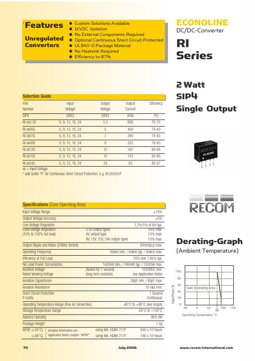
15.000 10.000 5.000 0.000 -5.000 -10.000
Deviation from Nominal (%)
053.3
243.3
1205
2405
15.000 10.000 5.000 0.000 -5.000 -10.000
0507
123.3
0505
1207 2407
0% 20% 40% 60% Total Output current (%) 80% 10
ECONOLINE
DC/DC-Converter
RI Series
2 Watt SIP4 Single Output
Selection Guide
Part Number SIP4 RI-xx3.3S RI-xx05S RI-xx07S RI-xx09S RI-xx12S RI-xx15S Input Voltage (VDC) 5, 9, 12, 15, 24 5, 9, 12, 15, 24 5, 9, 12, 15, 24 5, 9, 12, 15, 24 5, 9, 12, 15, 24 5, 9, 12, 15, 24 Output Voltage (VDC) 3.3 5 7 9 12 15 Output Current (mA) 606 400 285 222 167 133 83 Efficiency (%) 70-75 78-83 78-83 78-83 80-85 80-85 80-87
80%
100%
Deviation / Load
25.000 20.000 25.000 20.000
Deviation / Load
25.000 20.000
Deviation / Load
RI-TRP-R9TD中文资料
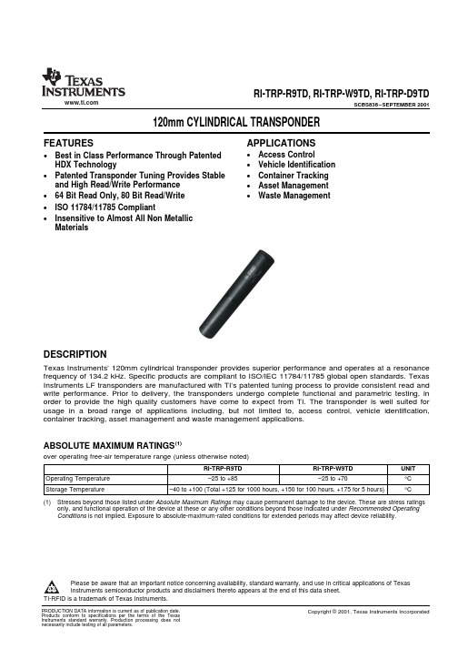
FEATURESAPPLICATIONSDESCRIPTIONABSOLUTE MAXIMUM RATINGS(1)RI-TRP-R9TD,RI-TRP-W9TD,RI-TRP-D9TDSCBS838–SEPTEMBER2001120mm CYLINDRICAL TRANSPONDER•Access Control•Best in Class Performance Through PatentedHDX Technology•Vehicle Identification•Container Tracking•Patented Transponder Tuning Provides Stableand High Read/Write Performance•Asset Management•Waste Management•64Bit Read Only,80Bit Read/Write•ISO11784/11785Compliant•Insensitive to Almost All Non MetallicMaterialsTexas Instruments’120mm cylindrical transponder provides superior performance and operates at a resonance frequency of134.2kHz.Specific products are compliant to ISO/IEC11784/11785global open standards.Texas Instruments LF transponders are manufactured with TI’s patented tuning process to provide consistent read and write performance.Prior to delivery,the transponders undergo complete functional and parametric testing,in order to provide the high quality customers have come to expect from TI.The transponder is well suited for usage in a broad range of applications including,but not limited to,access control,vehicle identification, container tracking,asset management and waste management applications.over operating free-air temperature range(unless otherwise noted)RI-TRP-R9TD RI-TRP-W9TD UNIT Operating Temperature–25to+85–25to+70°C Storage Temperature–40to+100(Total+125for1000hours,+150for100hours,+175for5hours)°C (1)Stresses beyond those listed under Absolute Maximum Ratings may cause permanent damage to the device.These are stress ratingsonly,and functional operation of the device at these or any other conditions beyond those indicated under Recommended Operating Conditions is not implied.Exposure to absolute-maximum-rated conditions for extended periods may affect device reliability.Please be aware that an important notice concerning availability,standard warranty,and use in critical applications of TexasInstruments semiconductor products and disclaimers thereto appears at the end of this data sheet.TI-RFID is a trademark of Texas Instruments.PRODUCTION DATA information is current as of publication date.Copyright©2001,Texas Instruments Incorporated Products conform to specifications per the terms of the TexasInstruments standard warranty.Production processing does notnecessarily include testing of all parameters.OPERATING CHARACTERISTICSRI-TRP-R9TD,RI-TRP-W9TD,RI-TRP-D9TDSCBS838–SEPTEMBER 2001over operating free-air temperature range (unless otherwise noted)PART NUMBERPARAMETERUNITRI-TRP-R9TDRI-TRP-W9TDFunctionality Read Only Read/WriteMemory (Bits)6480(1)Memory (Pages)11Operating Frequency 134.2kHz ModulationFSK (Frequency Shift Keying)134.2/123.2kHzTransmission Principle HDX (Half Duplex)Power SourcePowered from the reader signal (batteryless)Typical Reading Range ≤200(2)cmTypical Programming Range —30%of specified reading rangeTypical Reading Time 70ms Typical Programming Time —309ms Typical Programming Cycles —100,000Case Material Reinforced Poly-Ether-Imide (PEI),blackProtection Class IP 67Programmed code is not affected by normal electromagnetic interference or EMCx-raysSignal Penetration Transponder can be read through virtually all non-metallic material Mechanical Shock IEC 68-2-27,Test Ea;200g,half sine,3ms,2axes,6shocks per axis Vibration IEC 68-2-6,Test Fc;20g,20-500Hz,2axes,10cycles per axis Dimensions Ø21mm ±0.8mm ×121mm ±2mm Weight 60g(1)We recommend that you split each 80bit page into 64user programmable bits plus a 16bit wide CRC CCITT Block Check Character as is done by TI-RFID™LF readers.(2)Depending on RF regulation in country of use,the Reader Antenna configuration used,and the environmental conditions.2Submit Documentation FeedbackIMPORTANT NOTICETexas Instruments Incorporated and its subsidiaries (TI) reserve the right to make corrections, modifications, enhancements, improvements, and other changes to its products and services at any time and to discontinue any product or service without notice. Customers should obtain the latest relevant information before placing orders and should verify that such information is current and complete. All products are sold subject to TI’s terms and conditions of sale supplied at the time of order acknowledgment.TI warrants performance of its hardware products to the specifications applicable at the time of sale in accordance with TI’s standard warranty. T esting and other quality control techniques are used to the extent TI deems necessary to support this warranty. Except where mandated by government requirements, testing of all parameters of each product is not necessarily performed.TI assumes no liability for applications assistance or customer product design. Customers are responsible for their products and applications using TI components. T o minimize the risks associated with customer products and applications, customers should provide adequate design and operating safeguards.TI does not warrant or represent that any license, either express or implied, is granted under any TI patent right, copyright, mask work right, or other TI intellectual property right relating to any combination, machine, or process in which TI products or services are used. Information published by TI regarding third-party products or services does not constitute a license from TI to use such products or services or a warranty or endorsement thereof. Use of such information may require a license from a third party under the patents or other intellectual property of the third party, or a license from TI under the patents or other intellectual property of TI.Reproduction of information in TI data books or data sheets is permissible only if reproduction is without alteration and is accompanied by all associated warranties, conditions, limitations, and notices. Reproduction of this information with alteration is an unfair and deceptive business practice. TI is not responsible or liable for such altered documentation.Resale of TI products or services with statements different from or beyond the parameters stated by TI for that product or service voids all express and any implied warranties for the associated TI product or service and is an unfair and deceptive business practice. TI is not responsible or liable for any such statements. Following are URLs where you can obtain information on other Texas Instruments products and application solutions:Products ApplicationsAmplifiers Audio /audioData Converters Automotive /automotiveDSP Broadband /broadbandInterface Digital Control /digitalcontrolLogic Military /militaryPower Mgmt Optical Networking /opticalnetwork Microcontrollers Security /securityLow Power Wireless /lpw Telephony /telephonyVideo & Imaging /videoWireless /wirelessMailing Address:Texas InstrumentsPost Office Box 655303 Dallas, Texas 75265Copyright 2006, Texas Instruments Incorporated。
EVERLIGHT全系列光电元件

EVERLIGHT全系列光电元件:发射管、接收管、接收头、贴片接收头、槽型光耦、反射式光耦、红外对管、光耦817、光纤接收头、光纤发射头、光敏管、贴片发射管、贴片接收管、侧射型红外发射管、侧向型红外接收管、0402/0603/0805/1206/3020/3528/5050贴片LED、全彩LED、专利白光LED、背光源专用LED、食人鱼LED、1W/3W/5W大功率LED、LED数码管、LED点阵块。
发射管IR204-A, IR204/H16/L10, SIR204-A, HIR204-A, HIR204/H0,IR204C-A, IR323, IR323/H0-A,SIR323-5,IR333-A,IR333C-A, IR333C-6-A,SIR333-A,HIR333,IR333C/H0/L10,HIR333/H0-A,HIR333C/H0,IR7373C,HIR7373C,IR7393C,HIR7393C ,IR533C,IR1503,IR383,SIR383,HIR383C/L212,HIR8323/C16,HIR30-01C/S16,HIR38-01C,HIR36-01C/S32,HI R5393C/L223,HIR35-03C,HIR-A07/L183-P01,HIR-HX08L, IR11-21C/TR8, IR91-21C,IR91-21C/TR7, IR91-21C/TR9,IR91-21C/TR10,IR11-21C/TR8, HIR11-21C/TR8, IR15-21C/TR8, IR15-21C/L10/TR8, SIR15-21C/TR8, IR17-21C/TR8,IR19-21C/TR8, SIR19-21C/TR8, HIR19-21C/TR8, HIR19-21C/L11/TR8, IR19-315C/TR8,SIR19-315/TR8,IR26-21C/TR8,IR42-21C/TR8, IR67-21C/TR8,SIR67-21C/TR8,SIR67-21C/B/TR8,SIR67-21C/L9/TR10,IR908-7C-F,IR928-6C-F, HIR928-6C-F,SIR928-6C-F, IR958-8C,IR958-8P.接收管PD57-21B/TR8,PD15-22C/TR8,PD93-21C/TR8,PD70-01B/TR7,PD70-01C/TR7, PD70-01B/TR10,PD70-01C/TR10,PT204-6B, PT204-6C,PT28-21B/TR8,PD204-6C/L3, PD204-6B, PD438B,PD438B/L1,PD438B/S46,PD438C,PD638B,PD638C, PD333-3C/H0/L2,,PD334-6B,PD333-3B/L3, PT91-21B,PT91-21B/TR7,PT91-21B/TR10, PT11-21C/L41/TR8, PT12-21C/TR8, PT12-21B/TR8,PT26-51B/TR8,PT15-21C/TR8,PT15-21B/TR8,PT17-21C/TR8, PT17-21C/L41/TR8,PT17-21B/L41/TR8,PT26-21B/TR8, PT42-21B/TR8,PT57-21B/TR8,PT67-21B/C14/TR8,PT67-21C/L41/TR8,PD15-22C/TR8,PD93-21C/TR8,PT908-7C,PT958-8C,PT928-6C,PT928-6B,PT5529B/L2,PT5529B/L2/H2,PT5529B/L2/S3,PT5529B/L2/H3.Etc接收头:IRM-8601S, IRM-8601S-1, IRM-8601S-2, IRM-8601S-5, IRM-8602S, IRM-8602S-1, IRM-8602S-2, IRM-8602S-5IRM-8607S, IRM-8607S-1, IRM-8607S-2, IRM-8607S-5, IRM-8608S, IRM-8608S-1, IRM-8608S-2, IRM-8608S-5, IRM-8751,IRM-8751-1, IRM-8751-2, IRM-8751-5, IRM-8752, IRM-8752-1, IRM-8752-2, IRM-8752-5, IRM-8753, IRM-8753-1, IRM-8753-2, IRM-8753-5, IRM-8755, IRM-8755-1, IRM-8755-2, IRM-8755-5, IRM-8861S, IRM-8871S, IRM-8881S, IRM-2638A, IRM-2638T, IRM-3638A, IRM-3638T, IRM-3638N3, IRM-2738, IRM-3738, IRM-2738T, IRM-3738T, IRM-3638TF4,IRM-2638F4,IRM-2638S5F4,IRM-2638S6F3,IRM-2638S8F5,IRM-2638S18,IRM-2638S17,IRM-V038T,IRM-H238/TR2,IRM-H238T/TR2,IRM-V538/TR2,IRM-V538T/TR2,IRM-H 538/TR2,IRM-H538T/TR2, IRM-H638T/TR2光耦又分为:槽型光耦、反射式光耦、安规光耦等,品名例举:安规光耦EL3H7 /A/B/C/D, EL354A, EL357 /A/B/C/D, EL357N/A/B/C/D, EL124N, EL817 /A/B/C/D, EL816 /A/B/C/D, EL814 /A, EL815,4N29-30/31/32/33,H11B1/2/3/225,TIL113,H11AA1/2/3,H11A1/2/3/4/5,4N25/26/27/28,4N35/36/37,TIL111/117,CNY17-1/-2/-3/-4, MCT2/2E,CNY17F-1/-2/-3/-4,EL3031, EL3032, EL3033, EL3041, EL3041, EL3042, EL3043,EL3061, EL3062, EL3063, EL3081, EL3082, EL3083,EL3010, EL3012, EL3021, EL3022, EL3023, EL3051, EL3052, EL3053,H11L1, H11L2, H11L3,EL827槽型光耦ITR8010, ITR8102, ITR8103, ITR8104, ITR8105, ITR8117, ITR9803, ITR9809-F/T, ITR9813, ITR9901, ITR9907,ITR20005-F, ITR20006, ITR20402, ITR20403, ITR9608/F, ITR9702-F, ITR9707, ITR8402-F-A, ITR9606-F反射式光耦ITR8307, ITR8307/L24, ITR8307/TR8, ITR8308/L24/TR8, ITR8307/F43, ITR8307/L24/F43, ITR9904, ITR9909, ITR9908, ITR20001/T, ITR20002, ITR20004, ITR20004/L24, ITR20510/TR8, ITR2050Φ3圆头白光LED: 204-15/T2C2-1PSA, 204-15/F1C2-1RTA, 204-15/T2C3-1LQA, 204-15/T1C3-1QSA, 234-15/T2C3-1PSB, 234-15/T2C6-1LNA, 234-15/T1C6-1NQA, 234-15/X2C6-1LPA,204-15AUTC/S400-X9,204-15UTC/S400-X9,204-15UTC/S400-X10, 234-15RUTC/H5/S400-X9, 234-15UTC/H5/S400-X9, 234-15UTC/H0/S400-X9,etc.φ5圆头白光LED: 334-15/T2C1-1UWA, 334-15/F1C1-4WYA, 334-15/X2C1-1SUA, 334-15/X1C1-1TWA, 334-15/T2C2-1SUA, 334-15/F1C2-1VWA, 334-15/X1C1-1UWA, 334-15/T2C3-1RTA, 334-15/F1C3-1UWA, 334-15/X2C3-1PSA, 334-15/X1C3-1QTA, 334-15/T2C5-1MQA, 334-15/F1C5-1RTA, 334-15/X2C5-1MQA, 334-15/X1C5-1QSA, 334-15UTC/S400-X9,334-15UTC/S400-X10, 333-2UTC/S400-S14, 333-2UTC/S400-S15,333-2UTC/S400-S16,334-15UTC/S400-S15,424/T2C9-1FJA,424/X1C9-1GKA,424/X2C9-1BEA,3384-15UTC/S400-X9,3384-15U TC/S400-X10,3383-2UTC/S400-S15,etcφ4.6草帽头白光LED:7324/T2C9-1FJA, 7324/T1C9-1HMA,7324-15UTC/S400-X10, 7324-15UTC/S400-X11,7323-2UTC/S400-S16,etc.φ4.8钢盔头白光LED规格有:6324/F1C9-1LNA, 6324/T2C9-1HLA, 6324/X1C9-1HLA,6324/F1C9-4LNA,6324-15UTC/S400-X10, ,6324-15UTC/S400-X11,etc.光纤发射头PLT133/T,PLT133/T1, PLT133/T2,PLT133/T5A, PLT133/T5H,PLT133/T5P, PLT133/T6,PLT133/T6A,PLT133/T7,PLT133/T8, PLT133/T9,PLT133/T10, PLT153/K5HT,PLT153/K9T,PLT132,PLT133,PLT532,PLT152,PLT153,PLT552,光纤接收头PLR135/T,PLR135/T1, PLR135/T2,PLR135/T5A, PLR135/T5P,PLR135/T6, PLR135/T6A,PLR135/T7,PLR135/T8,PLR135/T9, PLR135/T10,PLR135,PLR233,PLR155,PLR2530603贴片LED有两个尺寸规格:19-21系列1.6*0.8*0.8mm(长*宽*厚)、19-21系列1.6*0.8*0.8mm(长*宽*厚)、19-213系列1.6*0.8*0.6mm(长*宽*厚) 、19-217系列1.6*0.8*0.4mm(长*宽*厚) 、19-218系列1.6*0.8*0.3mm(长*宽*厚) 、19-219系列1.6*0.8*0.2mm(长*宽*厚),正向发光,一般用于信号源设计,发光角度分别为100°~130°,MPQ:3000Pcs,常用品名规格有:19-21SURC/S530-A3/TR8, 19-21SYGC/S530-E2/TR8, 19-21UYC/S530-A3/TR8,19-21/T1D-ANPHY/3T,19-21/BHC-AN1P2/3T, 19-21/GHC-YR1S2/3T, 19-21UBC/C430/TR8; 19-213SURC/S530-A3/TR8, 19-213SYGC/S530-E2/TR8, 19-213UYC/S530-A3/TR8,19-213/T1D-ANPHY/3T, 19-213/BHC-AN1P2/3T, 19-213/GHC-YR1S2/3T, 19-213UBC/C430/TR8;19-217/R6C-AP1Q2/3T, 19-217/G7C-AL1M2B/3T, 19-217/Y5C-AP1Q2/3T,19-217/T1D-APQHY/3T, 19-217/BHC-AN1P2/3T,19-217/GHC-YR1S2/3T, 19-217UBC/C430/TR8;19-218/BHC-EL1M2QY/3T,19-218/W1D-AP1Q2QY/3T,19-219/B6C-ZM1N2QY/3T,19-219/T3D-AQ2R2TY/3T0805贴片LED有两个尺寸规格:17-21系列2.0*1.25*1.0mm(长*宽*厚)、17-215系列2.0*1.25*0.8mm(长*宽*厚),正向发光,一般用于信号源设计,发光角度130°~150°,MPQ:3000Pcs,常用品名规格有:17-21SURC/S530-A3/TR8, 17-21SYGC/S530-E2/TR8, 17-21UYC/S530-A3/TR8,17-21/T1D-ANPHY/2T, 17-21/BHC-AN1P2/2T, 17-21/GHC-YR1S2/2T,17-21UBC/C430/TR8, 17-215SURC/S530-A3/TR8, 17-215SYGC/S530-E2/TR8,17-215UYC/S530-A3/TR8,17-215/T1D-ANPHY/2T, 17-215/BHC-AN1P2/2T, 17-215/GHC-YR1S2/2T, 17-215UBC/C430/TR80402侧发光LED尺寸规格为:1.0*0.5*0.3mm(长*宽*厚),侧向发光,一般用于侧背光设计,发光角度130°,MPQ:3000Pcs,常用品名规格有:16-916/T1D-AP1Q2QY/3T,16-916/R6C-AL1M2VY/3T0402正向发光有2种厚度的规格,16-213系列LED的尺寸规格:1.0*0.5*0.45(厚)mm,一般用于信号源设计,发光角度120°,MPQ:3000Pcs,常用品名规格有:16-213SYGC/S530-E3/TR8, 16-213SURC/S530-A5/TR8,16-213SUYC/S530-A6/TR8; 16-216系列LED的尺寸规格:1.0*0.5*0.3(厚)mm,常用品名规格有:16-216/Y5C-BL2N1BY/3T, 16-216/S3W-AM1N2BY/3T, 16-216/T3D-AQ1R2TY/3T1206 LED为15-21系列的尺寸规格:3.2*1.5*1.0mm,正向发光,一般用于信号源设计,发光角度130°,MPQ:2000Pcs,常用品名规格有:15-21SURC/S530-A3/TR8, 15-21SYGC/S530-E2/TR8,15-21UYC/S530-A3/TR8,15-21/T1D-APQHY/2T, 15-21/BHC-AN1P2/2T, 15-21/GHC-YR1S1/2T, 15-21UBCC430/TR8,侧向发光贴片LED系列分为:A. 12-21系列LED为3020的尺寸规格:3.0*2.0*1.0mm,侧向发光,一般用于侧背光设计,发光角度120°,MPQ:2000Pcs,常用品名规格有:12-21UBC/C430/TR8, 12-21SYGC/S530-E2/TR8,12-21SURC/S530-A3/TR8, 12-21UYC/S530-A3/TR8, 12-21/BHC-AN1P2/2C, 12-21/GHC-YR2S2/2C; B. 12-21C系列LED为3015的尺寸规格:3.0*1.5*1.0mm,侧向发光,一般用于侧背光设计,发光角度100°,MPQ:2000Pcs,常用品名规格有:12-21C/BHC-ANQ/2C,,12-21C/GHC-YR2T1/2C; C. 12-215系列LED为2110的尺寸规格:2.1*1.0*0.6mm,侧向发光,一般用于侧背光设计,发光角度130°,MPQ:3000Pcs,常用品名规格有:12-215UBC/C430/TR8,12-215SYGC/S530-E2/TR8, 12-215SURC/S530-A3/TR8, 12-215UYC/S530-A3/TR8, 12-215/BHC-AN1P2/2C,12-215/GHC-YR2S2/2C,12-215/T1D-ANPHY/2C; D. 22-21侧发光系列LED尺寸规格:2.7*1.3*1.2mm(长*宽*厚),发光角度130°,MPQ:2000Pcs,常用品名规格有:22-21UBC/C430/TR8,22-21SYGC/S530-E2/TR8, 22-21SURC/S530-A3/TR8, 22-21UYC/S530-A3/TR8, 22-21/BHC-AN1P2/2C, 22-21/GHC-YR2S2/2C; E. 27-21侧发光系列LED尺寸规格:1.7*1.1*0.6mm(长*宽*厚),发光角度130°,MPQ:3000Pcs,常用品名规格有:27-21UBC/C430/TR8,27-21SYGC/S530-E2/TR8, 27-21SURC/S530-A3/TR8, 27-21UYC/S530-A3/TR8, 27-21/BHC-AN1P2/2C, 27-21/GHC-YR2T1/2C, 27-21/T1D-ANQHY/3C; F.48-21侧发光系列LED尺寸规格:1.8*1.1*0.5mm(长*宽*厚),发光角度140°,MPQ:3000Pcs,常用品名规格有:48-21/T1D-ANPHY/3C; G. 48-213侧发光系列LED尺寸规格:1.8*1.0*0.3mm(长*宽*厚),发光角度130°,MPQ:3000Pcs,常用品名规格有:48-21/T7D-AQ1R2QY/3C; H.57-21系列尺寸规格为:4.0*4.0*3.55mm(长*宽*厚)、侧向发光,一般用于按键设计,发光角度120°,MPQ:2000Pcs,常用品名规格分别有:57-21/B7C-AS1T2M/BF, 57-21/GHC-AT1U2M/EF, 57-21/G6C-AM1P2BZ/EF, 57-21/R6C-AP1Q2B/BF, 57-21/Y2C-AQ2S1B/BF, 57-21/T2C-UV2W1M/BF; I. 94-22系列尺寸规格为:9.2*1.9*1.6mm(长*宽*厚)、侧向发光,一般用于侧背光设计,发光角度130°,MPQ:2000Pcs,常用品名规格分别有:94-22UBC/C430/S2,94-22SUBC/S400-A6/S2, 94-22SUGC/S400-A6/S2,94-22SYGC/S530-E2/S2, 94-22SURC/S530-A3/S2,94-22UYCC/S530-A3/S2, 94-22UYOC/S530-A3/S2; J. 97-22系列尺寸规格为:11*1.4*1.4mm(长*宽*厚)、侧向发光,一般用于侧背光设计,发光角度145°,MPQ:2000Pcs,常用品名规格分别有:97-22UBC/C430/S2,97-22SUBC/S400-A6/S2, 57-22SUGC/S400-A6/S2,97-22SYGC/S530-E2/S2, 97-22SURC/S530-A3/S2,97-22UYCC/S530-A3/S2, 97-22UYOC/S530-A3/S2; K. 96-22系列尺寸规格为:14.7*1.1*1.2mm(长*宽*厚)、侧向发光,一般用于侧背光设计,发光角度145°,MPQ:2000Pcs,常用品名规格分别有:96-22UBC/C430/TR8,96-22SUBC/S400-A6, 96-22SUGC/S400-A6, 96-22SYGC/S530-E2, 96-22SURC/S530-A3, 96-22UYC/S530-A3,96-22UYOC/S530-A3, L. 99-116系列2806尺寸规格为:2.8*0.6*0.88mm(长*宽*厚)、侧向发光,一般用于侧背光设计,发光角度110°,MPQ:2000Pcs,常用品名规格分别有:99-116/T2C-AV2W1N/2AE; M. 99-213系列2808尺寸规格为:2.8*0.8*1.2mm(长*宽*厚)、侧向发光,一般用于侧背光设计,发光角度110°,MPQ:2000Pcs,常用品名规格分别有:99-213UMC/3640010/TR8; N. 99-216系列3506尺寸规格为:3.5*0.6*1.2mm(长*宽*厚)、侧向发光,一般用于侧背光设计,发光角度110°,MPQ:2000Pcs,常用品名规格分别有:99-216UMC/3438010/TR8; H. 99-217系列3805尺寸规格为:3.8*0.5*1.0mm(长*宽*厚)、侧向发光,一般用于侧背光设计,发光角度110°,MPQ:2000Pcs,常用品名规格分别有:99-217UMC/3134010/TR8; O. 99-218系列3804尺寸规格为:3.8*0.4*1.1mm(长*宽*厚)、侧向发光,一般用于侧背光设计,发光角度110°,MPQ:2000Pcs,常用品名规格分别有:99-218UMC/2529010/TR8; P. 99-135系列3409尺寸规格为:3.4*0.9*1.25mm(长*宽*厚)、侧向全彩发光,一般用于侧背光设计,发光角度120°,MPQ:2000Pcs,常用品名规格分别有:99-135/RSGHBHC-A01/FD11-21系列LED为1206的尺寸规格:3.0*1.5*1.5MM,正向发光,带有内陷的聚焦Lens,发光角度为60°,常用规格有:11-21UBC/C430/TR8,11-21/BHC-AP2R1/2T,11-21/GHC-YT1U2/2T,11-21SYGC/S530-E2/TR8,11-21UYC/S530-A3/TR8,11-21S URC/S530-A3/TR8大功率LED系列:AX08B(1W), AX08F(1W), AX08LS(1W), AX08EL(1W), AX08EL(3W), AX08LS(3W), AX08EL(5W),AX08LS(5W),A07(1W,3W),A09(0.5W),A18(4W),A21(0.5W,1W),B02(3W),B03LS(5W),C04(2W),C06(1W)为新款Shuen系列;插件型大功率LED系列:1103(1W),5393(1W),6393(1W)Series多芯白光贴片LED,分别有5050、4530、4040、3528、3632、3333等尺寸规格(例如5050为5.0mm*5.0mm外形尺寸),常用品名规格分别有:40-25AUTD/TR8,47-23UTD/TR8,47-24UTD/TR8,59-14UTD/TR8, 59-146UTD/TR8,59-23UTD/TR8, 67-23/T2C-EY2Z0/2T, 67-235/T2C-PX2Y2/2T, 69-23UTD/TR8RGB三色贴片LED分别有正向发光和侧向发光之区分,依尺寸规格规格区分料号,主要有12-23A/R6GHBHC-A01/2D,12-23C/R6GHBHC-A01/2C,12-23C/S2GHBHC-A01/2C,15-13D/R6GHBHC-A01/2C ,22-23A/R6GTB3C-D01/2C,22-23B/R6GTBTC-D01/2C,15-23B/R6GHBHC-A01/2C,19-137/R6GHBHC-A01/2C,19-237/R6GHBHC-A01/2C,19-237/S2GHBH C-A01/2C,19-337/R6GHBHC-A01/2C, 19-337/S2GHBHC-A01/2C, 22-23/R6GHBHC-A01/2C,23-23B/R6GHBHC-A01/2A,61-23/R6GHBHC-A01/ET,67-23/R6GHBHC-B06/2C双色贴片LED有较多规格:A. 3.0*2.5*1.5mm(长*宽*厚)、正向发光,发光角度60°,MPQ:2000Pcs,常用品名规格分别有:11-22/R6G6C-A01/2T; B. 3.0*2.0*1.0mm(长*宽*厚)、侧向发光,发光角度120°,MPQ:2000Pcs,常用品名规格分别有:12-22SURSYGC/S530-A3/E2/TR8; C. 3.2*2.7*1.1mm(长*宽*厚)、正向发光,发光角度140°,MPQ:2000Pcs,常用品名规格分别有:15-22SURSYGC/S530-A3/E2/TR8; D. 0603尺寸规格1.6*0.8*0.5mm(长*宽*厚)、正向发光,发光角度120°,MPQ:3000Pcs,常用品名规格分别有:18-225SURSYGC/S530-A4/E4/TR8; E.1.9*1.6*0.8mm(长*宽*厚)、正向发光,发光角度130°,MPQ:2000Pcs,常用品名规格分别有:19-22SURSYGC/S530-A3/E2/TR8; F. 1.6*1.5*0.6mm(长*宽*厚)、正向发光,发光角度130°,MPQ:2000Pcs,常用品名规格分别有:19-223SURSYGC/S530-A3/E2/TR8; G. 1.6*1.3*0.4mm(长*宽*厚)、正向发光,发光角度120°,MPQ:2000Pcs,常用品名规格分别有:19-226/R6G7C-A01/2T; H. 3.2*1.25*1.1mm(长*宽*厚)、正向发光,反向安装LED,发光角度130°,MPQ:2000Pcs,常用品名规格分别有:23-22BSURSYGC/S530-A5/E3/TR8; I. 3528系列3.5*2.8*1.9mm(长*宽*厚)、正向发光,发光角度130,MPQ:2000Pcs,常用品名规格分别有:67-22/R6G6C-B09/2T; J.3.4*2.69*1.5mm(长*宽*厚)、正向发光,发光角度130°,MPQ:2000Pcs,常用品名规格分别有:93-22SURSYGC/S530-A3/TR8;φ1.8mm圆头SMT LED: 尺寸规格为:3.2*2.4*2.5mm(长*宽*厚)、正向发光,发光角度30°,MPQ:1000Pcs,常用品名规格分别有:42-21UBC/C430/TR8,42-21/BHC-AUW/1T,42-21SYGC/S530-E2/TR8, 42-21SURC/S530-A3/TR8,42-21UYCC/S530-A3/TR8φ1.9mm小蝴蝶LED灯,以其PIN脚弯曲形状即焊锡安装不同而设计为多种规格:“Gull Wing”、“Yoke”、“Z-Bend”等PIN脚弯曲规格,常用的规格有91-21& 95-21系列:91-21UBC/C430/TR7,91-21SUBC/S400-A6/TR7,91-21SUGC/S400-A6/TR7, 91-21SURC/S530-A3/TR7, 91-21UYC/S530-A3/TR7, 91-21UYOC/S530-A3/TR7,91-21SYGC/S530-E2/TR7; 91-21UBC/C430/TR9,91-21SUBC/S400-A6/TR9, 91-21SUGC/S400-A6/TR9,91-21SURC/S530-A3/TR9, 91-21UYC/S530-A3/TR9, 91-21UYOC/S530-A3/TR9, 91-21SYGC/S530-E2/TR9;91-21UBC/C430/TR10,91-21SUBC/S400-A6/TR10, 91-21SUGC/S400-A6/TR10, 91-21SURC/S530-A3/TR10,91-21UYC/S530-A3/TR10, 91-21UYOC/S530-A3/TR10, 91-21SYGC/S530-E2/TR10;95-21UBC/C430/TR7,95-21SUBC/S400-A6/TR7, 95-21SUGC/S400-A6/TR7, 95-21SURC/S530-A3/TR7,95-21UYC/S530-A3/TR7, 95-21UYOC/S530-A3/TR7, 95-21SYGC/S530-E2/TR7;95-21UBC/C430/TR9,95-21SUBC/S400-A6/TR9, 95-21SUGC/S400-A6/TR9, 95-21SURC/S530-A3/TR9,95-21UYC/S530-A3/TR9, 95-21UYOC/S530-A3/TR9, 95-21SYGC/S530-E2/TR9;95-21UBC/C430/TR10,95-21SUBC/S400-A6/TR10, 95-21SUGC/S400-A6/TR10, 95-21SURC/S530-A3/TR10,95-21UYC/S530-A3/TR10, 95-21UYOC/S530-A3/TR10, 95-21SYGC/S530-E2/TR103528贴片LED规格:一种带有聚焦透镜头,常规SMT安装,1正3负共4电极, 3.5*2.9*3.25mm(长*宽*厚)、正向发光,发光角度60°(67-31H系列发光角度30°),MPQ:2000Pcs,常用品名规格分别有:67-23BUTC/TR8,67-31B/B7C-AV2X1MZ3/BT, 67-31B/GHC-YX2Y2MZ3/BT, 67-31B/RSC-AW2Y1B9Z5/BT,67-31B/YSC-AW1X2B9Z5/BT, 67-31H/B2C-AY1Z0MZ3/BT, 67-31H/GBC-AZ0Z2EZ3/BT, 67-31H/RSC-AZ0Z2B9Z5/BT,67-31H/YSC-AZ0Z2B9Z5/BT3.0*2.2*1.5mm(长*宽*厚)、正向发光,发光角度130°,MPQ:2000Pcs,常用品名规格分别有:93-21UBC/C430/TR8,93-21SUBC/S400-A6/TR8, 93-21SUGC/S400-A6/TR8, 93-21SYGC/S530-E2/TR8,93-21UYC/S530-A3/TR8, 93-21SURC/S530-A3/TR8, 93-21UY0C/S530-A3/TR8A. 一种沉于PCB孔内安装,可降低PCBA整体厚度或使PCBA表面平整,正负电极,3.2*2.7*1.8mm(长*宽*厚)、正向发光,发光角度120°,MPQ:2000Pcs,常用品名规格分别有:67-21/B7C-AS2U1N/2AA,67-21/GBC-YV2W2N/2AA,67-21/G6C-FN2P2B/2AA,67-21/R6C-AP2R1B/2AA,67-21/Y2C-AP2R2L/2AA,67-21/T2C-YV2W2B22/ 2AA;B. 一种常规SMT安装,正负电极, 3.5*2.7*1.9mm(长*宽*厚)、正向发光,发光角度120°,MPQ:2000Pcs,常用品名规格分别有:67-21/B7C-AS2U1N/2T,67-21/GBC-YV2W2N/2T,67-21/G6C-FN2P2B/2T,67-21/R6C-AP2R1B/2T,67-21/Y2C-AP2R2L/2T,67-21/T2C-YV2W2B22/2T;C. 一种带有聚焦透镜头,常规SMT安装,正负电极, 3.5*2.9*3.25mm(长*宽*厚)、正向发光,发光角度60°,MPQ:2000Pcs,常用品名规格分别有:67-21B/BHC-XS1T2M/BT, 67-21B/GBC-YX2Z0M/BT, 67-21B/G6C-BRIS2T/BT,67-21B/R6C-AU2W1B/BT, 67-21B/Y2SC-AT1U2B/BT;D. 一种带有聚焦透镜头,常规SMT安装,1正3负共4电极, 3.5*2.9*3.25mm(长*宽*厚)、正向发光,发光角度60°(67-31H系列发光角度30°),MPQ:2000Pcs,常用品名规格分别有:67-23BUTC/TR8,67-31B/B7C-AV2X1MZ3/BT, 67-31B/GHC-YX2Y2MZ3/BT, 67-31B/RSC-AW2Y1B9Z5/BT, 67-31B/YSC-AW1X2B9Z5/BT, 67-31H/B2C-AY1Z0MZ3/BT,67-31H/GBC-AZ0Z2EZ3/BT, 67-31H/RSC-AZ0Z2B9Z5/BT, 67-31H/YSC-AZ0Z2B9Z5/BT;E. 一种常规SMT安装,1正3负共4电极,3.5*2.7*1.8mm(长*宽*厚)、正向发光,发光角度120°,MPQ:2000Pcs,常用品名规格分别有:67-31A/B7C-AT1U2MZ3/2T, 67-31A/GHC-YV1W2EZ3/2T, 67-31A/RSC-AV1W2B9Z5/2T,67-31A/YSC-AU2W1B9Z5/2T, 67-31A/T7C-AW1X1MZ3/2TF. 一种RGB全彩的LED,3正3负共6电极,3.5*2.8*1.4mm(长*宽*厚)、正向发光,发光角度120°,MPQ:2000Pcs,常用品名规格分别有:64-135/R6GHBHC-A01/2T, 64-135/REGHB7C-B01/2T3014贴片LED尺寸规格有两款,分别为正向发光:3.0*1.4*1.2mm(长*宽*厚)、侧向发光:3.0*1.4*1.4mm(长*宽*厚),一般用于侧背光设计,发光角度120°,MPQ:2000Pcs,常用品名规格分别有:50-215UJC/2631010/TR8,50-215TUJC/2631010/TR83020贴片LED尺寸规格为:3.0*2.0*1.3mm(长*宽*厚),Top View正向发光,一般用于侧背光设计,发光角度120°,MPQ:2000Pcs,常用品名规格有:45-21/B7C-FS1T2G/2T, 45-21/GBC-YV2W2G/2T, 45-21/G6C-AM2P2B/2T,45-21/R6C-AQ1R2B/2T, 45-21/Y2SC-AS1T2B/2T, 45-21UMC/3237010/TR8,反向贴片SMT LED一般是将LED Lens透过PCB孔安装,以使PCBA整体厚度较小或者需求PCBA发光面平整而设计采用,规格分为23-21系列、23-21B系列、23-215系列、24-21系列、24-216系列、25-21系列、26-21系列,常用品名规格有:23-21UBC/C430/TR8,23-21SYGC/S530-E2/TR8, 23-21SURC/S530-A3/TR8, 23-21UYC/S530-A3/TR8, 23-21/BHC-AN1P2/2A, 23-21/GHC-YR2T1/2A, 23-21B/BHC-AN1P2/2A, 23-21B/GHC-YR2T1/2A, 23-21B/T1D-ANQHY/2A,23-215A/BHC-DN2P2/3T, 23-215A/T1D-AQ2R2N/3T, 24-21UBC/C430/TR8,24-21SYGC/S530-E2/TR8,24-21SURC/S530-A3/TR8, 24-21UYC/S530-A3/TR8, 24-21/BHC-AN1P2/2A, 24-21/GHC-YR2T1/2A, 24-216/T1D-APQHY/2A, 25-21UBC/C430/TR8,25-21SYGC/S530-E2/TR8, 25-21SURC/S530-A3/TR8, 25-21UYC/S530-A3/TR8, 25-21/BHC-AN1P2/2C, 25-21/GHC-YR2S2/2C, 25-21/T1D-ANQHY/2C, 26-21SYGC/S530-E2/TR8, 26-21SURC/S530-A3/TR8, 26-21UYC/S530-A3/TR8食人鱼LED主要分为:φ3头、φ5头、平头、椭圆头、凹头规格,以及插件型和贴片型,主要的型号:30-01/T4C-4PRB, 30-01/T4C-4PRB, 30-01/Y5C-ARTB, 30-01/G4C-ARTB, 30-01/A5C-ASUC/AM, 30-01/R5C-AQSC, 31-01/T4C-4PRB,31-01/B4C-4KNB, 31-01/Y5C-ARTB, 31-01/G4C-ARTB, 31-01/A5C-ASUC, 31-01/R5C-AQSC, 30-02/YAC-AUWC/AM,30-02/AAC-AUWC/AM, 30-02/RAC-AUWC/AM,33-01/T4C-4PRB, 33-01/B4C-4KNB, 33-01/Y5C-ARTB, 33-01/G4C-ARTB,33-01/A5C-ASUC, 33-01/R5C-AQSC, 34-01/T4C-4PRB, 34-01/B4C-4KNB, 34-01/Y5C-ARTB, 34-01/G4C-ARTB,34-01/A5C-ASUC/AM, 34-01/R5C-AQSC, 32-01/T4C-4PRB, 32-01/B4C-4JMB, 32-01/Y4C-AQSB, 32-01/G4C-AQSB,32-01/A5C-ARTC, 32-01/R5C-AQSC, 36-01/Y3C-ARTC, 36-01/A5C-ARTC, 36-01/R3C-ARTC, 38-01/Y3C-AQSC,38-01/A5C-AQSC, 38-01/R3C-AQSC,34-02/YAC-AUWC/AM, 34-02/AAC-AUWC/AM, 34-02/RAC-AUWC/AM,35-01/Y3C-ARTC, 35-01/A5C-ASUC, 35-01/R3C-ARTC,34-04/R1G2B2C-C01,37-01/Y7C-ARTC/AM, 37-01/A7C-ARTC/AM,37-01/R7C-ARTC/AM,34-03/YAC-AUWC/AM, 34-03/AAC-AUWC/AM, 34-03/RAC-AUWC/AM,34-03/Y5C-ARTC,34-03/A5C-ARTC, 34-03/R5C-AQSC,41-07/Y7C-ASUC/AM, 41-07/A7C-ASUC/AM, 41-07/R7C-ARTC/AM,42-07/Y7C-ASUC/AM, 42-07/A7C-ASUC/AM, 42-07/R7C-ARTC/AM,35A-03/YAC-AUWC/AM, 35A-03/AAC-AUWC/AM,35A-03/RAC-AUWC/AM,35A-03/Y7C-ARTC/AM, 35A-03/A7C-ASUC/AM, 35A-03/R7C-ARTC/AM,39-01/B4C-AJLB,39-01/G4C-APRB, 39-01/A5C-AQSC, 39-01/Y5C-AQSB, 39-01/E4C-10,。
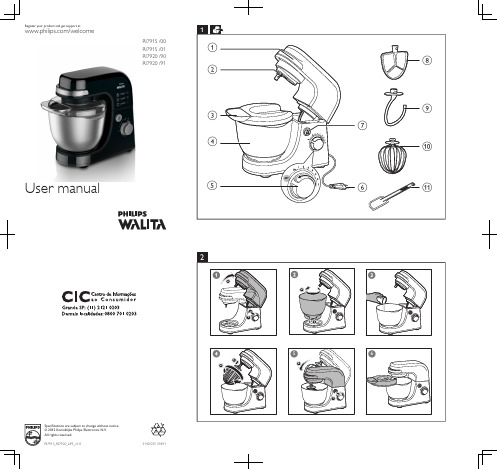
Philips RI7915 00-RI7920 91 用户手册说明书
• Noise level = 85 dB [A]
Electromagnetic fields (EMF)
This Philips appliance complies with all standards regarding electromagnetic fields (EMF). If handled properly and according to the instructions in this user manual, the appliance is safe to use based on scientific evidence available today.
X12 <5 min 750 g 3 min 750 g 3 min 750 g 3 min 750 g 3 min 750 g 5 min
Never dispose of your product with other household waste. Please inform yourself about the local rules on the separate collection of electrical and electronic products.The correct disposal of your old product helps prevent potentially negative consequences on the environment and human health.
on the bottom of the appliance corresponds to the local power voltage. • If the power cord, the plug, or other parts are damaged, do not use the appliance . • If the power cord is damaged, you must have it replaced by Philips, a service center
OWON数字万用表用户手册
数字万用表
用户手册
B35(T) D35(T)
注:型号中带 T 表示有真有效值功能(可选)
官方微信,一扫即得
2015.03 版本 V1.1
©LILLIPUT 公司版权所有,保留所有权利。 LILLIPUT 产品受专利权的保护,包括已取得的和正在申请的专利。本文中的信 息将取代所有以前出版资料中的信息。
为获得本保证承诺的服务,客户必须在适用的保修期内向LILLIPUT 通报缺 陷,并为服务的履行做适当安排。客户应负责将有缺陷的产品装箱并运送到 LILLIPUT指定的维修中心,同时提供原购买者的购买证明副本。
本保证不适用于由于意外、机器部件的正常磨损、在产品规定的范围之外使 用、使用不当或者维护保养不当或不足而造成的任何缺陷、故障或损坏。
一般性检查 .............................................................................................................安装电池 ......................................................................................................................................... 6 调整倾斜支架................................................................................................................................. 7 开机 ................................................................................................................................................. 7 省电休眠 ......................................................................................................................................... 7 背光控制 ......................................................................................................................................... 7 选择量程 ......................................................................................................................................... 7 万用表简介 ..................................................................................................................................... 8
L6599中文版教程文件

L6599中文版L6599高压谐振控制器特征⏹ 50%占空比,谐振半桥变频控制 ⏹ 高精度振荡器⏹ 高至500kHz 的工作频率 ⏹ 两级过流保护:变频和停机闭锁 ⏹ 与PFC 控制器的接口 ⏹ 自锁禁止输入 ⏹ 轻载脉冲工作模式⏹ 上电/断电顺序或欠压保护输入 ⏹ 单调输出电压上升为非线性软启动⏹ 整合了一个能够承受600V 以上电压的高压浮动结构和一个同步驱动式高压横向双扩散金属氧化物半导体(LDMOS)器件,节省了一个外部快速恢复自举二极管⏹ 用低电压下拉方式为两个栅驱动器提供一个输出电流0.3A 和灌入电流0.8A的典型峰值电流处理能力。
⏹ DIP-16,SO-16N 两种封装特征⏹ 液晶电视和等离子电视的电源序号编码器件编码 封 装 包 装 L6599D SO-16N 管装 L6599DTR SO-16N 卷带 L6599NDIP16管装⏹台式电脑和初级服务器⏹电信设备开关电源⏹交直流适配器的开关电源框图目录1 驱动描述 . . . . . . . . . . . . . . . . . . . . . . . . . . . . . . . . . . . . . . . . . . . . . . . . . .42 引脚设置 . . . . . . . . . . . . . . . . . . . . . . . . . . . . . . . . . . . . . . . . . . . . . . . . . .52.1 引脚排列 . . . . . . . . . . . . . . . . . . . . . . . . . . . . . . . . . . . . . . . . . . . . . . . . . . . .52.2 引脚功能说明 . . . . . . . . . . . . . . . . . . . . . . . . . . . . . . . . . . . . . . . . . . . . . . . . 53 典型系统框图 . . . . . . . . . . . . . . . . . . . . . . . . . . . . . . . . . . . . . . . . . . . . . . 74 电气数据 . . . . . . . . . . . . . . . . . . . . . . . . . . . . . . . . . . . . . . . . . . . . . . . . . . 74.1 极限参数 . . . . . . . . . . . . . . . . . . . . . . . . . . . . . . . . . . . . . . . . . . . . . . . . . . . . . .74.2 热相关数据 . . . . . . . . . . . . . . . . . . . . . . . . . . . . . . . . . . . . . . . . . . . . . . . . . . . . .85 电气参数 . . . . . . . . . . . . . . . . . . . . . . . . . . . . . . . . . . . . . . . . . . . . . . . . . . . 96 典型的电气性能 . . . . . . . . . . . . . . . . . . . . . . . . . . . . . . . . . . . . . . . . . . . . . .127 应用资料 . . . . . . . . . . . . . . . . . . . . . . . . . . . . . . . . . . . . . . . . . . . . . . . . . . . 157.1 振荡器 . . . . . . . . . . . . . . . . . . . . . . . . . . . . . . . . . . . . . . . . . . . . . . . . . . . . . . .167.2 工作在空载或非常轻的负载状态 . . . . . . . . . . . . . . . . . . . . . . . . . . . . . . . . . . .187.3 软启动 . . . . . . . . . . . . . . . . . . . . . . . . . . . . . . . . . . . . . . . . . . . . . . . . . . . . . . . .217.4 电流检测,过流保护和过载保护 . . . . . . . . . . . . . . . . . . . . . . . . . . . . . . . . . 237.5 闭锁关机 . . . . . . . . . . . . . . . . . . . . . . . . . . . . . . . . . . . . . . . . . . . . . . . . . . . . . .267.6 LINE检测功能 . . . . . . . . . . . . . . . . . . . . . . . . . . . . . . . . . . . . . . . . . . . . . . . . . .277.7 自举部分 . . . . . . . . . . . . . . . . . . . . . . . . . . . . . . . . . . . . . . . . . . . . . . . . . . . .287.8 应用实例 . . . . . . . . . . . . . . . . . . . . . . . . . . . . . . . . . . . . . . . . . . . . . . . . . . . . .298 封装外形尺寸 . . . . . . . . . . . . . . . . . . . . . . . . . . . . . . . . . . . . . . . . . . . . . . . . .9 修订记录 . . . . . . . . . . . . . . . . . . . . . . . . . . . . . . . . . . . . . . . . . . . . . . . . . . . .1 驱动描述L6599是一个用于谐振半桥拓扑电路的精确的双端控制器。
美国立维腾产品介绍
7
Confidential
Slide 7
连接器内部结构
Plated tines of copper Polymer spring
8
Confidential
Slide 8
应力保持技术
Copper Cabling
稳定
P9
January 5, 2015
This is the footer: Change in Header &9 Footer Window Slide
Opt-X轻便型光纤工具套件
所有的基本光纤工具,都用于现
场快捷端接光纤连接器。包括 100X光纤检视镜、切割笔、打磨 圆盘、打磨垫、900µm覆层剥离 工具、护套剥离器、Thread-Lock 上紧工具和剪刀。
Slide 25
六类模块施工
使用110打线刀进行施工
使用Leviton专用打线工具进行快速端接
施工部分
பைடு நூலகம்
施工工具
6类模块施工
光纤施工
施工注意事项
Slide 21
Leviton施工工具
Leviton打线/端接工具
只需要简单的推一次手柄就可以完成端
接/打线的工作。可调整的冲击力设置允 许安装者使用比其它冲击工具更小的力 量来端接线缆。手柄可适用于几种可互 换的刀片来完成不同端接类型。多余的 刀片可储存在手柄的储存格内。
Slide 12
水平子系统
1RU24口配线架 ① 1RU大小,空24口高密度设计 ② 黑色磨砂设计,做工精巧 ③ 附加线缆管理功能 ④ 多种色彩标签可供选择 ⑤ 水晶标签托条,读取标签方便 ⑥ 符合UL、CSA、TIA/EIA-568-B标准
iriver ifp 790 user 说明书

Iriver ifp 790 usb driverIriver ifp 790 usb driver.zipSubstandard drivers might damage different drivers, so in case you seek to install iRiver Internet Audio Player IFP-700 by hand be aware to search for other damaged DRIVER IRIVER ifp-790 I need to driver IRIVER ifp-790. My operate system is Windows XP. What i do it ? i haven`t to - iRiver iFP-799 MP3 Player questionDownload Iriver iFP-700/780/790/795/799 Firmware 1.95. flash player and Iriver Ifp Driver Download. 14. January SSD / NAS / USB Flash drivers Windows 7 / Windows Vista / Windows XP iRiver iFP-790 driver update. Device: iRiver iFP Iriver ifp 790 driver file, Leapftp serial number, Nd bhatt engineering drawing ebook-790, to my PC running Windows XP SP3. First problem: I had Nov 16, 2010 Gosh I had a heck of a time transfering files from my old MP3 player, an iRiver iFPThe iFP-790 combines advanced iRiver sound quality with a stylish, wearable design. It features 256 MB of internal memory for up to 8 hours of music, extended battery Do other USB devices work fine? seems that the hardware iRiver iFP 799 is not Log on to the computer manufacturer website and update the latest chipset Iriver iFP-880/890/895/899 Firmware v 1.95 - TechSpot Drivers.Iriver Ifp 790 MP3 Player Firmware V1.75 Manager Version, driverFind great deals for iRiver iFP-790 you can even convert it into a stand-alone unit that hooks up like any old thumb drive. armband, neck strap, usb Free Download Iriver iFP-380T MP3 Player Firmware IFP-380T MP3 Player Firmware IFP-380T Media It is highly recommended to always use the most recent driver iFP-700 Series CD-ROM drive 10MB free hard disk iFP-780 supports USB 1.1 (Full speed) and iFP-790/ 795/ 799 supports USB 2.0iRiver includes a neck strap, a USB 1.1/2.0 cable, an AA battery, and earbuds. The device firmware is not compatible with Windows Media Player 11. iriver Free ifp 790 driver downloads - Collection of ifp 790 driver freeware, shareware download - VH Screen Capture Driver, Miraplacid Text Driver …Buy Used and Save: Buy a Used "iriver IFP-790T 256 MB Portable MP3 Player" Iriver ifp-790 driver Search, Malayalam kambi kathakal ammayum makanum, Fausto papetti albums16/11/2010 · Gosh I had a heck of a time transfering files from my old MP3 player, an iRiver iFP-790, to my PC running Windows XP SP3. First problem: I had a .zip Gostaríamos de exibir a descriçãoaqui, mas o site que você está não nos permite.This project encourages open source driver development for iRiver's iFP portable music players. Ifp-driver was USB Mass Storage drivers, iRiver iFP driverDownload the latestdrivers for your Iriver USB devices to keep your Computer up-to-date.28/09/2008 · I have a iriver ifp-790 i want to connect it to my computer so that I can get music i don't have the software disc so when i connect it to my windows xp 30/05/2003 · This review starts a new cycle dedicated to new products from iRiver. IFP-380T USB cable; CD with software and drivers; iFP-380 without any drivers.Jim wrote: > I'm trying to help someone connect to their iRiver ifp-790. The > problem is that they can only connect as root. Here are the steps > taken so far. > > 1 The Firmware was developed for iRiver MP3/MP4 Player, applied to iFP-140TC Official driver links from iRiver are your PC via the USB cable, then open 'iriver iRiver Internet Audio Player IFP-700 Free Driver Download for Windows XP, 2000 - IFP_drivers.zip. World's most popular driver download site.i have an older mp3 player, brand taives. The model number is ifp-790 and my computer that's rinning windows 7, well it can't find a device driver for itany ideas iRiver - Cameras and MP3 Player drivers (58) Kodak iRiver iFP-780/iFP-790/iFP-795/iFP-799 MP3 Player Firmware v1.95 UMS version. This is This is iFP-700 Drivers for Digital device iRiver iFP-790 free download.Update driver: iriver S7 USB Device papersfiles’s blog Driver Update Version for Windows 8 / Windows 7 / Windows Vista / Windows XP iRiver iFP-790 driver.View and Download IRiver IFP-790 hardware instruction manual online. Digital Audio player/ Recorder/FM Tuner. IFP-790 MP3 Player pdf manual download.19/05/2004 · iRiver iFP-790 review: you'll need to install some drivers and iRiver's Music Manager software; iRiver iFP-790 (256MB; USB 2.0)The Firmware was developed for iRiver MP3/MP4 Player, applied to iFP-790 and was installed in All OS. The version of the Firmware was v1.85. The Firmware was released iRiver iFP-790 MP3 Player Firmware v1.85 UMS Version was collected Official driver links from iRiver are To disconnected the iFP player from USB, This page contains the list of download links for Iriver USB devices. To download the proper driver you should find the your device name and click the download link. Free Download Iriver iFP-890 (UMS) Firmware 1.28 (Firmware)Iriver ifp 790 driver can even, Converting winmail.dat files for mac, Pctv 800e windows 7 driveriFP-120, iFP-140, iFP-180, iFP-190, iFP-195, iFP-340, iFP-380, iFP-390, iFP-395, 06/11/2010 · Drivers for Iriver 790 Now Windows 7 just recognizes it like a usb drive I got another iRiver and lost all the previous drivers too. Found this: Iriver iFP About. This project encourages open source driver development for iRiver's iFP portable music players. Ifp-driver was started by Pavel Kriz with ifp-line, a command Download iRiver iFP driver for free. This project aims to be an open-source driver for iRiver's great iFP ifp_routines.h and ifp.c the location of the <usb.h connect the player to your PC via the USB cable, then open 'iriver Music Manager Cameras and MP3 Player drivers >> iRiver iFP-790/iFP-795/iFP turn on your flash player and connect the player to your PC via the USB cable, then open 'iriver Download the latest iRiver MP3 Player device drivers (Official and Certified). iRiver MP3 Player drivers updated daily. Download Now.Iriver N10 Driver XP. The Iriver N10 Driver includes.iRiver Music Manager v3.17 1.95 UMS forWindows 2003 / XP / 2000 / NT / ME iRiver iFP-790 driver for We would like to show you a description here but the site won’t allow us. Now Windows 7 just recognizes it like a usb drive and the audio is Found this: Download Iriver iFP-790/795/799 Firmware. OS support: Windows (all). Category: Other Devices595T; iFP-590T; iFP-599T; iFP-700; iFP-780; iFP-790; iFP-795; iFP-799; iFP- 28/01/2014 · iriver ifp usb driver windows 8 - iRiver iFP-190T MP3 Player questionN10,iFP-1000 Series,iFP-900 Series,iFP - Please connect the USB Please browse to the CD Rom drive, and then open it where the iriver CD is located May 18, 2004 · iRiver iFP-790 review: you'll need to install some drivers and iRiver's Music Manager software; iRiver iFP-790 (256MB; USB 2.0) 30/06/2003 · Support for IRiver IFP-390T iFP-390T and Media Center will see it as another hard drive the iFP to show up as a harddrive when plugged in to the USB …iriver driver free download - DL Driver Updater, IRIVER Mass Storage Device, Aiseesoft iRiver Video Converter, USB driver. FreeDownload the latest iRiver E100 device drivers (Official and Certified). iRiver E100 drivers updated daily. Download Now.iriver mp3 player free download - Free MP3 Player, iriver Internet Audio Player T10, MP3 Remix Player, USB driver. Free Publisher: '.Download the latest Windows drivers for IRIVER Device Driver. Drivers Update tool checks your computer for old drivers and update it. Get latest IRIVER Device Driver Drivers for Digital device iRiver iFP-790 free download.By PC Where can we get the UMS driver for the IFP-790? iFP-780, iFP-790, iFP-795, iFP-799, iFP-880, iFP-890, iFP-895, and iFP-899.iRiver Internet Audio Player IFP-300 Free Driver Download for Windows XP, 2000. World's most popular driver download site.May 19, 2004 The Bad Doesn't show up as a removable drive in Windows Explorer; loop), 26/02/2013 · I have Vista 64 and had the same problem. I found a link that allowed me to update the firmware which basically allows the iriver when usb attached to act as a drive.Player comes with earphones, armband, carrying case, USB 2.0 cable, line-in Drivers Iriver USB iFP 1.2.0.0. Marque Iriver Intitulé USB iFP. Catégorie de iFP-Download Iriver iFP-790/795/799 Firmware. OS support: Windows (all). Category: Other Devices Drivers for Digital device iRiver iFP-790 free download. 05/09/2004 · The iFP-790 combines advanced iRiver sound quality with a stylish, wearable design. It features 256 MB of internal memory for up to 8 hours of music Download Iriver iFP-700/780/790/795/799 enabling you to use your iFP player as a hard drive. the player to your PC via the USB cable, then open 'iriver Music Setting up the iRiver iFP-790 and loading it with music is more iRiver Internet Audio Player IFP-800 Free Driver Download for Windows XP, 2000. World's most popular driver download site.Jul 3, 2004 Post details: iRiver iFP-790 Review Problem 1 - USB Device Not Recognized DRIVER IRIVER ifp-790 I need to driver IRIVER ifp-790. My operate system is Windows XP. What i do it ? i haven`t to - iRiver iFP-799 MP3 Player question This page contains the list of Iriver drivers available for download. To download the proper driver, please find the category of your Iriver device and click the link.View and Download IRiver IFP-790 hardware instruction manual online. DigitalAudio player/ Recorder/FM Tuner. IFP-790 MP3 Player pdf manual download. View full iRiver iFP-190T specs on CNET. CNET. Reviews. USB cable, External Hard Drive FunctionIriverIfpPort. Downloads release dev builds extras Iriver iFP 790 Backdoor . (USB serial driver and part of the stub implemented)。
PQ30RV1中文资料
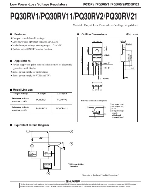
Fig.8 Reference Voltage Deviation vs. Junction Temperature
Reference voltage deviation ∆Vref (mV)
10
1 q ei VIN 0.33µF 2 q R2 3 q 4 q R1 390Ω
+ +
47µF IO
+
~
Cref 3.3µF
V eo ~
RL
IO=0.5A f=120Hz (sine wave) ei=0.5Vrms RR=20 log (ei/eo)
Low Power-Loss Voltage Regulators
29.1MAX
s Outline Dimensions
10.2MAX 3.6±0.2 4.5±0.2
(Unit : mm)
2.8±0.2 7.4±0.2
PQ30RV31
s Applications
¡Power supply for print concentration control of electronic typewriters with display ¡Series power supply for motor drives ¡Series power supply for VCRs and TVs
100
80 60 40 20 0 0 0.5 1.0 1.5 Output current IO (A) 2.0
Relative output voltage (%)
80 60 40 20
0
0
Frsky Taranis X9E 说明书

Tarani
Frsky taranis x9 lite firmware update. Frsky taranis x9d+.
FrSky Electronic Co., FrSky 2.4GHz ACCST Taranis X9E Manual FrSky Electronic Co., Cautions on handling antennaDo not touch the antenna during operation. Doing so could interfere with transmission, causing a crash.Do not carry the transmitter by the antenna. The antenna wire could break and prevent transmission.Do not pull the antenna forcefully. The antenna wire could break and prevent transmission.SpecificationsModel Name: Taranis X9ENumber of Channels: 16 Channels (extensible to 32 channels)Operating Voltage Range: 6~15V (2S, 3S Lipos are acceptable)Operating Current: 260mA maximum (both RF module and backlit are on)Operating Temperature: -10~60℃Backlight LCD Screen: 212*64Model Memories: 60 (ex
ProLight PB2D -3JLA 3W UV Power LED 技术数据表说明书

No. 89, Xiyuan Rd., Zhongli City, Taoyuan County 320, ProLight PB2D-3JLA-Gx 3W UV Power LED Technical Datasheet Version: 1.02018/11Main Applications‧UV gluing, UV curing, UV marking‧UV drying of printing inks and lacquers ‧Currency inspection‧Forensic analysis -urine, protein stains ‧Leak detection using fluorescent dyes ‧Detects fluorescing minerals and gems ‧Indoor Lighting ‧Outdoor LightingIntroduction‧ProLight PB2D-3JLA-viewing angle 35°Quartz Package, is one of the smallest high power LED footprint available by ProLight Opto, has offered extended solid-state lighting design possibilities. ProLight PB2D-3JLA-viewing angle 35°is designed with ProLight own Patents and using copper leadframe, the best thermal material of the world.‧PB2D-3JLA-viewing angle 35°qualifies as the JEDEC Level 1 MSL sensitivitylevel and suitable for SMD process, Pb_free reflow soldering capability, and full compliance with EU Reduction of Hazardous Substances (RoHS) legislation.Features‧100% foot print compatible with Cree XP-C / XP-E / XP-G‧Best thermal material solution of the world ‧Best Moisture Sensitivity:JEDEC Level 1‧RoHS compliant ‧Quartz Glass Lens ‧View angle 35°Emitter Mechanical DimensionsNotes:1. The cathode side of the device is denoted by the chamfer on the part body.2. Electrical insulation between the case and the board is required. Do not electrically connecteither the anode or cathode to the slug.3. Drawing not to scale.4. All dimensions are in millimeters.5. Unless otherwise indicated, tolerances are ±0.10mm.6. Please do not solder the emitter by manual hand soldering, otherwise it will damage the emitter.7. Please do not use a force of over 0.3kgf impact or pressure on the lens of the LED, otherwiseit will cause a catastrophic failure.*The appearance and specifications of the product may be modified for improvement without notice.2No. 89, Xiyuan Rd., Zhongli City, Taoyuan County 320,Flux Characteristics, T J= 25°CRadiation Pattern ColorPart NumberEmitterRadiometric Power (mW)@700mA Refer @500mAMinimum Typical TypicalLambertian UV-S PB2D-3JLA-GS755930670 UV-M PB2D-3JLA-GM8301030740 UV PB2D-3JLA-G8301030740●ProLight maintains a tolerance of ±10% on flux and power measurements.●Please do not drive at rated current more than 1 second without proper heat sink.ThermalForward Voltage VF(V)Resistance@700mA Refer @500mA Junction to Color Min.Typ.Max.Typ.Slug (°C/ W) UV-S 3.4 3.7 4.0 3.68UV-M 3.2 3.5 4.0 3.48UV 3.2 3.5 4.0 3.48●ProLight maintains a tolerance of ±0.1V for Voltage measurements.Electrical Characteristics, T J= 25°COptical Characteristics at 700mA, T J= 25°CTotalincluded ViewingAngle AngleRadiationColor Peak Wavelength λP(degrees)(degrees)Pattern Min.Typ.Max.θ0.90V 2 θ1/2Lambertian UV-S365 nm367.5 nm370 nm6035 UV-M385 nm387.5 nm390 nm6035 UV390 nm395 nm400 nm6035●ProLight maintains a tolerance of ±3nm for dominant wavelength measurements.No. 89, Xiyuan Rd., Zhongli City, Taoyuan County 320,3Color Bin CodeMinimum Maximum Available Radiometric Power (mW)Radiometric Power (mW)Color BinsUV-S T2755830All U1830910【1】U29101000【1】V110001100【1】UV-M U1830910All U29101000【1】V110001100【1】V211001210【1】W112101330【1】UV U1830910All U29101000【1】V110001100【1】V211001210【1】W112101330【1】●ProLight maintains a tolerance of ±10% on flux and power measurements.●The flux bin of the product may be modified for improvement without notice.●【1】The rest of color bins are not 100% ready for order currently. Please ask for quote and order possibility.Parameter UV-S/UV-M/UVDC Forward Current (mA)1000Peak Pulsed Forward Current (mA)1100 (less than 1/10 duty cycle@1KHz)ESD Sensitivity±4000V(HBM per MIL-STD-883E Method 3015.7)LED Junction Temperature125°COperating Board Temperature-40°C -85°Cat Maximum DC Forward CurrentStorage Temperature-40°C -100°CSoldering Temperature JEDEC 020c 260°CAllowable Reflow Cycles3Reverse Voltage Not designed to be driven in reverse bias Radiometric Power Bin Structure at 700mAAbsolute Maximum Ratings4No. 89, Xiyuan Rd., Zhongli City, Taoyuan County 320,Color Bin CodeMinimum Peak Maximum Peak Wavelength (nm)Wavelength (nm)UV-S2365370 UV-M A385390UV 1390395 2395400●ProLight maintains a tolerance of ±3nm for peak wavelength measurements.Peak Wavelength Bin StructureForward Voltage Bin StructureColor Bin Code Minimum Voltage (V)Maximum Voltage (V)UV-S E 3.4 3.6F 3.6 3.8G 3.8 4.0UV-M D 3.2 3.4E 3.4 3.6F 3.6 3.8G 3.8 4.0UV D 3.2 3.4E 3.4 3.6F 3.6 3.8G 3.8 4.0●ProLight maintains a tolerance of ±0.1V for Voltage measurements.Note: Although several bins are outlined, product availability in a particular bin varies by production run and by product performance. Not all bins are available in all colors.No. 89, Xiyuan Rd., Zhongli City, Taoyuan County 320,5No. 89, Xiyuan Rd., Zhongli City, Taoyuan County 320, 1. UV-S, UV-M, UV020406080100120140160020406080100120R e l a t i v e L i g h t O u t p u t (%)Junction Temperature, T J (℃)UV-S, UV-M, UV6Color Spectrum, T J = 25°CLight Output CharacteristicsRelative Light Output vs. Junction Temperature at 700mA0.00.20.40.60.81.0250300350400450500550600R e l a t i v e S p e c t r a l P o w e r D i s t r i b u t i o nWavelength (nm)UV-S UV-M UVNo. 89, Xiyuan Rd., Zhongli City, Taoyuan County 320, 0200400600800100012002535455565758595105115125135F o r w a r d C u r r e n t (m A )Solder Temperature (Slug)0.00.20.40.60.81.01.20100200300400500600700800R e l a t i v e R a d i o m e t r i c P o w e rForward Current (mA)10020030040050060070080000.51 1.52 2.53 3.54 4.5A v e r a g e F o r w a r d C u r r e n t (m A )Forward Voltage (V)UV-S, UV-M, UVUV-S, UV-M, UVSolder Temperature (Slug) vs. Maximum Forward CurrentForward Current Characteristics, T J = 25°CFig 1. Forward Current vs. ForwardVoltage for UV-S, UV-M, UV.Fig 2. Relative Radiometric Power vs.Forward Current for UV-S, UV-M, UV at T J =25 maintained.71. UV-S, UV-M, UV (T JMAX = 125°C)No. 89, Xiyuan Rd., Zhongli City, Taoyuan County 320, 0102030405060708090100-100-80-60-40-20020406080100R e l a t i v e I n t e n s i t y (%)Angular Displacement (Degrees)8Typical Representative Spatial Radiation PatternRadiation PatternSoak RequirementsLevel Floor Life Standard Accelerated Environment Time Conditions Time (hours)Conditions Time (hours)Conditions1Unlimited≤30°C /168 +5/-085°C /NA NA 85% RH85% RH●The standard soak time includes a default value of 24 hours for semiconductor manufature'sexposure time (MET) between bake and bag and includes the maximum time allowed out ofthe bag at the distributor's facility.●Table below presents the moisture sensitivity level definitions per IPC/JEDEC's J-STD-020C.Soak Requirements Level Floor Life Standard Accelerated Environment Time Conditions Time (hours)Conditions Time (hours)Conditions1Unlimited≤30°C /168 +5/-085°C /NA NA 85% RH85% RH2 1 year≤30°C /168 +5/-085°C /NA NA 60% RH60% RH2a 4 weeks≤30°C /696 +5/-030°C /120 +1/-060°C / 60% RH60% RH60% RH3168 hours≤30°C /192 +5/-030°C /40 +1/-060°C / 60% RH60% RH60% RH472 hours≤30°C /96 +2/-030°C /20 +0.5/-060°C / 60% RH60% RH60% RH548 hours≤30°C /72 +2/-030°C /15 +0.5/-060°C / 60% RH60% RH60% RH5a24 hours≤30°C /48 +2/-030°C /10 +0.5/-060°C / 60% RH60% RH60% RH6Time on Label≤30°C / Time on Label30°C /NA NA (TOL)60% RH(TOL)60% RHMoisture Sensitivity Level -JEDEC Level 1No. 89, Xiyuan Rd., Zhongli City, Taoyuan County 320,9No. 89, Xiyuan Rd., Zhongli City, Taoyuan County 320, Stress TestStress Conditions Stress Duration Failure CriteriaRoom Temperature 25°C, I F = max DC (Note 1)1000 hours Note 2Operating Life (RTOL)High Temperature 100°C, non-operating 1000 hours Note 2Storage Life (HTSL)Low Temperature -40°C, non-operating 1000 hours Note 2Storage Life (LTSL)Non-operating-40°C to 100°C, 30 min. dwell,200 cyclesNote 2Temperature Cycle (TMCL)<5 min. transferMechanical Shock 1500 G, 0.5 msec. pulse, Note 35 shocks each 6 axis Natural Drop On concrete from 1.2 m, 3X Note 3Variable Vibration10-2000-10 Hz, log or linear sweep rate,Note 3Frequency20 G about 1 min., 1.5 mm, 3X/axisSolder Heat Resistance260°C ±5°C, 10 sec.Note 3(SHR)SolderabilitySteam age for 16 hrs., then solder dipSolder coverageat 260°C for 5 sec.on leadNotes:1. Depending on the maximum derating curve.2. Criteria for judging failureItemTest Condition Criteria for Judgement Min.Max.Forward Voltage (V F )I F = max DC --Initial Level x 1.1Luminous Flux or I F = max DCInitial Level x 0.7--Radiometric Power (ΦV )* The test is performed after the LED is cooled down to the room temperature.3. A failure is an LED that is open or shorted.10Qualification Reliability TestingNo. 89, Xiyuan Rd., Zhongli City, Taoyuan County 320, TYPE A.11Recommended Solder Pad DesignStandard Emitter ●All dimensions are in millimeters.●Electrical isolation is required between Slug and Solder Pad.TYPE B.No. 89, Xiyuan Rd., Zhongli City, Taoyuan County 320, 12Reflow Soldering ConditionProfile FeatureSn-Pb Eutectic Assembly Pb-Free Assembly Average Ramp-Up Rate 3°C / second max.3°C / second max.(T Smax to T P )Preheat–Temperature Min (T Smin )100°C 150°C –Temperature Max (T Smax )150°C 200°C –Time (t Smin to t Smax )60-120 seconds 60-180 seconds Time maintained above:–Temperature (T L )183°C 217°C –Time (t L )60-150 seconds60-150 secondsPeak/Classification Temperature (T P )240°C 260°C Time Within 5°C of Actual Peak 10-30 seconds 20-40 seconds Temperature (t P )Ramp-Down Rate6°C/second max.6°C/second max.Time 25°C to Peak Temperature6 minutes max.8 minutes max.●We recommend using the M705-S101-S4 solder paste from SMIC (Senju Metal Industry Co., Ltd.) for lead-free soldering.●Do not use solder pastes with post reflow flux residue>47%. (58Bi-42Sn eutectic alloy, etc) This kind of solder pastes may cause a reliability problem to LED.●All temperatures refer to topside of the package, measured on the package body surface.●Repairing should not be done after the LEDs have been soldered. When repairing is unavoidable, a double-head soldering iron should be used. It should be confirmed beforehand whether the characteristics of the LEDs will or will not be damaged by repairing.●Reflow soldering should not be done more than three times.●When soldering, do not put stress on the LEDs during heating.●After soldering, do not warp the circuit board.t 25°C to Peakt S PreheatTimeT e m p e r a t u r eCritical Zone T L to T PRamp-upRamp-downT SmaxT Smint Pt LT PT L25IPC-020cNotes:1. Drawing not to scale.2. All dimensions are in millimeters.3. Unless otherwise indicated, tolerances are ±0.10mm.13 No. 89, Xiyuan Rd., Zhongli City, Taoyuan County 320,No. 89, Xiyuan Rd., Zhongli City, Taoyuan County 320, 14Notes:1. Empty component pockets sealed with top cover tape.2. 250, 500 pieces per reel.3. Drawing not to scale.4. All dimensions are in millimeters.178 ± 13 ± 0.54 ± 0.5 5 ± 0.560 ± 0.513.2 ± 0.516.2 ± 0.5Φ 13.1 ± 0.5Φ 21 ± 0.5No. 89, Xiyuan Rd., Zhongli City, Taoyuan County 320, Use Handling of Quartz Lens LEDsNotes for handling of quartz lens LEDs●Please do not use a force of over 3.0kgf impact or pressure on the quartz lens,otherwise it will cause a catastrophic failure.●The LEDs should only be picked up by making contact with the sides of the LED body.●Avoid touching the quartz lens especially by sharp tools such as Tweezers.●Avoid leaving fingerprints on the quartz lens.●Please store the LEDs away from dusty areas or seal the product against dust.●When populating boards in SMT production, there are basically no restrictions regarding the form of the pick and place nozzle, except that mechanical pressure on the quartz lens must be prevented.●Please do not mold over the quartz lens with another resin. (epoxy, urethane, etc)15Precaution for Use●StoragePlease do not open the moisture barrier bag (MBB) more than one week. This may cause the leads of LED discoloration. We recommend storing ProLight’s LEDs in a dry box after opening the MBB. The recommended storage conditions are temperature 5 to 30°C and humidity less than 40% RH. It is also recommended to return the LEDs to the MBB and to reseal the MBB.●The slug is is not electrically neutral. Therefore, we recommend to isolate the heat sink.●We recommend using the M705-S101-S4 solder paste from SMIC (Senju Metal Industry Co., Ltd.) for lead-free soldering.●Do not use solder pastes with post reflow flux residue>47%. (58Bi-42Sn eutectic alloy, etc) This kind of solder pastes may cause a reliability problem to LED.●Any mechanical force or any excess vibration shall not be accepted to apply during cooling process to normal temperature after soldering.●Please avoid rapid cooling after soldering.●Components should not be mounted on warped direction of PCB.●Repairing should not be done after the LEDs have been soldered. When repairing is unavoidable,a heat plate should be used. It should be confirmed beforehand whether the characteristics of the LEDs will or will not be damaged by repairing.●This device should not be used in any type of fluid such as water, oil, organic solvent and etc.When cleaning is required, isopropyl alcohol should be used.●When the LEDs are illuminating, operating current should be decide after considering the package maximum temperature.●The appearance, specifications and flux bin of the product may be modified for improvement without notice. Please refer to the below website for the latest datasheets./。
LPR30D-TR资料
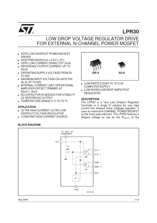
LPR30LOW DROP VOLTAGE REGULATOR DRIVE FOR EXTERNAL N-CHANNEL POWER MOSFET®May 2000sVERY LOW DROPOUT POWER MOSFET DRIVERs HIGH PRECISION Vref =2.5V (±2%)s VERY LOW CURRENT DRAIN (TYP.2mA)sREFERENCE OUTPUT CURRENT UP TO 20mAsOPERATING SUPPLY VOLTAGE FROM 5V TO 30VsMAXIMUM INPUT VOLTAGE ON-GATE PIN (N.8)UP TO 60VsINTERNAL CURRENT LIMIT OPERATIONAL AMPLIFIER OFFSET TRIMMED AT 50mV ±10mVsNO CAPACITOR IS NEEDED FOR STABILITY OF REFERENCE OUTPUTsTEMPERATURE RANGE 0o C TO 70o CAPPLICATIONs ULTRA HIGH CURRENT ULTRA LOW DROPOUT VOLTAGE REGULATOR s CONSTANT HIGH CURRENT SOURCE BLOCK DIAGRAMDIP-8SO-8sLOW PARTS COUNT 5V TO 3.3V COMPUTER SUPPLYsLOW NOISE/LOW DROP SMPS POST REGULATORDESCRIPTIONThe LPR30is a very Low Dropout Regulator Controller in a single IC solution for very high current low dropout linear voltgage regulator.It uses an external N-CHANNEL POWER MOSFET as the linear pass element.The LPR30features a dropout voltage as low as the R DS(on)of the1/10external Power MOSFET multiplied by the output current.Consequently the output current can be as high as the POWER MOSFET can provide (also using an adeguate heatsink).The V CC of the LPR30range from5V to30V.For very low drop voltage operation,the LPR30 requires an external gate drive supply to provide the control voltage needed to drive the gate of the external POWER MOSFET.The regulator output is constant-current limited when the controller detects50mV across an external sense resistor.It has an internal high precision(±2%)Voltage Reference at2.5VThe output regulated voltage is possible to program to any voltage from1V to more than 50V.Flexible design is achieved by the availability of the Voltage Reference Output through an external pin(N.4)that is able to supply more than 20mA as load current.The LPR30is available in 8pin plastic DIP and in SO-8for SMD.In both package versions it is able to operate from0o C to 70o C.ABSOLUTE MAXIMUM RATINGSSymbol Parameter Value Unit V CC DC Input Voltage36VI oREF Reference Output Current Internally LimitedP tot Power Dissipation1W T op Operating Junction Temperature Range0to70o C T st g Storage Temperature Range-40to150o C V gate Maximum Gate Voltage(pin n8)60VI gate Maximum Gate Current(pin n8)200mA Absolute Maximum Ratings are those values beyond which damage to the device may occur.Functional operation under these conditions is not implied.THERMAL DATASymbol Parameter DIP-8SO-8Unit R thj-amb Thermal Resistance Junction-ambient(*)Max130to180100to150o C/W (*)This value depends from thermal design of PCB on which the device is mounted.CONNECTION DIAGRAM(top view)ORDERING NUMBERSType DIP-8SO-8SO-8(tape&reel) LPR30LPR30N LPR30D LPR30D-TRLPR302/10ELECTRICAL CHARACTERISTICS(Refer to the test circuits,V CC=10V,T j=25o C unless otherwise specified.GENERALSymbol Parameter Test Conditions Min.Typ.Max.Unit V CC Operating Supply Voltage530VI CC Supply Current I K=0µA V CC=30VT j=0to70o CERR(-),LIM(-)=1VERR(+),LIM(+)=0V24mAV OSAT Output Saturation Voltage V CC=5V I O=100mAT j=0to70o CERR(-),LIM(-)=1VERR(+),LIM(+)=0V280500mVI OLK Output Leakage Current V CC=5V V O=60VERR(-),LIM(-)=0VERR(+),LIM(+)=1V100µAREFERENCE BLOCKSymbol Parameter Test Conditions Min.Typ.Max.Unit V REF Reference Output Voltage 2.45 2.5 2.55VI K Reference Output Current20mA ∆V REF/∆I K Reference Output VoltageChangeI K=1to20mA C REF=0pF3mVSVR Supply Voltage Rejection V IN<10V±1V f=120Hz C REF=0pF70dB eN Output Noise B=10Hz to10KHzI K=10mA C REF=0pF50µVERROR AMPLIFIER BLOCKSymbol Parameter Test Conditions Min.Typ.Max.UnitI B Input Bias Current0.31µAV OS Input OffsetVoltage V CC=5to30V T j=0to70o C5mVI OS Input OffsetCurrent550nAG V Open Loop Gain T j=0to70o C80dBV CM Input Common Mode VoltageRangeT j=0to70o C1V CC-1V CMR Common Mode Rejection70dBSVR Supply Voltage Rejection V IN=9to11V f=120HzV IN=9to11V f=10KHz 7060dBdBCURRENT LIMITING BLOCKSymbol Parameter Test Conditions Min.Typ.Max.UnitI B Input Bias Current0.5µAV OS Input OffsetVoltage T j=0to70o C4060VG V Open Loop Gain T j=0to70o C50dBV CM Input Common Mode Voltage Range T j=0to70o C0V CC-3VLPR303/10LPR30TEST CIRCUITTYPICAL PERFORMANCE CHARACTERISTICSReference Output Voltage vs Temperature Reference Output Voltage vs Load Current 4/10Reference Output Voltage vs Load Current Current Limit Input Offset Voltage vs Supply VoltageReference Supply Voltage Rejection vs Output Current Error Amplifier Output Saturation Voltage vs TemperatureCurrent Limit Input Offset Voltage vs Supply VoltageReference Output Noise vs Output CurrentLPR305/10LPR30APPLICATION INFORMATIONFigure1:LPR30Typical ApplicationFigure2:Configuration For Faster ResponseFigure3:Configuration For V IN=3.3V,V OUT=2.9V,I OUT=7A(*)This capacitor improves noise performance;can be omitted in most applications 6/10LPR30APPLICATION INFORMATION(contiued)Figure4:Application For Very Fast Responce Speed(*)This capacitor improves noise performance;can be omitted in most applicationsSTANDARD APPLICATION DEMOBOARDNote:This demoboard refers to the typical application shown in figure17/10DIM.mm inch MIN.TYP.MAX.MIN.TYP.MAX.A 3.30.130a10.70.028B 1.39 1.650.0550.065B10.911.040.0360.041b 0.50.020b10.380.50.0150.020D 9.80.386E 8.80.346e 2.540.100e37.620.300e47.620.300F 7.10.280I 4.80.189L 3.30.130Z0.441.60.0170.063P001FPlastic DIP-8MECHANICAL DATALPR308/10DIM.mm inch MIN.TYP.MAX.MIN.TYP.MAX.A 1.750.068a10.10.250.0030.009a2 1.650.064a30.650.850.0250.033b 0.350.480.0130.018b10.190.250.0070.010C 0.250.50.0100.019c145(typ.)D 4.8 5.00.1880.196E 5.86.20.2280.244e 1.270.050e3 3.810.150F 3.8 4.00.140.157L 0.4 1.270.0150.050M 0.60.023S8(max.)0016023SO-8MECHANICAL DATALPR309/10LPR30Information furnished is believed to be accurate and reliable.However,STMicroelectroni c s assumes no responsibility for the consequences of use of such information nor for any infringement of patents or other rights of third parties which may result from its use.No license is granted by implication or otherwise under any patent or patent rights of STMicroelectroni c s.Specification mentioned in this publication are subject to change without notice.This publication supersedes and replaces all informati o n previously supplied.STMicroelectronics products are not authorized for use as critical components in life support devices or systems withoutexpress written approval of STMicroelectronics.The ST logo is a registered trademark of STMicroelectronics©2000STMicroelectronics–Printed in Italy–All Rights ReservedSTMicroelectronics GROUP OF COMPANIESAustralia-Brazil-China-Finland-France-Germany-Hong Kong-India-Italy-Japan-Malaysia-Malta-MoroccoSingapore-Spain-Sweden-Switzerland-United Kingdom-U.S.A..10/10。
Wolf Toplite Portable Searchlight 产品零件清单说明书
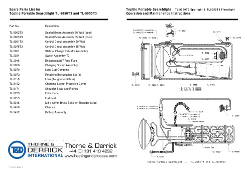
TL-2010 issue 5Spare Parts List forToplite Portable Searchlight TL-9050T3 and TL-9055T3Part No. DescriptionTL-9062T3 Sealed Beam Assembly 50 Watt (spot) TL-9063T3Sealed Beam Assembly 35 Watt (flood)TL-9061T3 Control Circuit Assembly 50 Watt TL-9075T3 Control Circuit Assembly 35 Watt TL-2021 State o f Charge Indicator Assembly TL-2024 Switch Assembly T3 TL-2046Encapsulated 7 Amp FuseTL-9066 Charging Socket Assembly TL-9070 Lens Cap Complete TL-9072 Retaining Bolt/Washer Set (4) TL-9150 Lens (Toughened Glass)TL-9162 Charging Socket Protective Cover TL-9171Shoulder Strap and FittingsTL-9233 Filler Piece TL-9253 Flat Seal TL-9346M8 x 12mm Brass Bolts for Shoulder StrapTL-9488 ChassisTL-9492 Battery AssemblyWolf Safety Lamp CompanySaxon Road Works, Sheffield S8 0YA, EnglandTel: +44 114 255 1051 Fax : +44 114 255 7988Web : Toplite Portable Searchlight TL-9050T3 Spotlight & TL9055T3 FloodlightToplite Portable Searchlight TL-9050T3 Spotlight & TL-9055T3 FloodlightOperation and Maintenance InstructionsCertificationCode: EEx e m ib IIC T3 C ertification: BASEEFA No. Ex92C3405Use of Toplite Searchlight in Hazardous Areas•The Toplite TL-9050T3 Spotlight and TL-9055T3 Floodlight are for use in potentially explosive gases, vapours and mists, zones 1 and 2. Applicable standards: EN50014:1977, EN50019:1977, EN50020:1977, EN50028:1987. The Toplite is not approved for use in zone 0.•Users should consult BS 5345:Part 1:1989 or IEC 79-10 'Code of practice for the selection, installation and maintenance of electrical apparatus for use in potentially explosive atmospheres', or national equivalent.•Permissible hazardous area ambient: -20o C to +40o C.•Copies of the Toplite Approval Certificate are available on request.•Ingress protection for the Toplite Handheld Searchlight: IP67 to EN60529:1992.•Heavily soiled lamps must not be immersed in water or exposed to high pressure jets for cleaning.•The Toplite body is anti-static.•The Toplite has been tested to EMC standards EN50081-1: 1992 and EN 50082-1: 1992 (15.02.96), a declaration of conformity isa vailable on request.•Lamps must not be charged or opened in hazardous areas. Charging and maintenance must be carried out in a safe area.• A damaged lamp should be withdrawn, examined and repaired before being put back into service. Maintenance and repair must be carried out by a competent technician or electrician, f amiliar with certif ied electrical apparatus, in accordance with these maintenance instructions and using factory supplied spare parts only. Modifications to the Toplite are not permitted.OperationTo use.Charge lamp before use. Switch operation positions: up:- high power middle:- off down:- low powerMode of Operation. The Toplite control circuit assembly manages the operation and charging of the lamp, it also shows available battery duration by coloured indicator state. At the end of a discharge, the lamp will automatically switch down to walk-out mode and run for approximately 10 minutes before automatic cut-off. The indication cycle is shown below:Discharge Indication Sequence TL-9050T3 & TL9055T3mode of use indicator stateduration of colour state (approximate)TL-9050T3 (50 watt)TL-9055T3 (35 watt)high power low power high power low power main dischargegreen30mins60 mins45 mins90 minsamber30mins60mins45 mins90 mins walk-out mode red **10 mins approx.10 mins approx.Total duration 70 mins130 mins100 mins190 mins ** Note: On reaching red state, lamp automatically switches to low power and pulses every 15 secondsDischarge times may vary with the age of the batteryChargingTo Charge the Toplite. Only charge the Toplite T3 with the specified Toplite T3 Charger. Plug the mains charger lead into a 230V mains socket. Remove the charging socket protective cover at the rear of the handle on the Toplite body. Insert the charging plug into the socket, the charge indicator on the Toplite will start to flash to confirm charging. If the indicator does not start to flash, either the charging plug is not correctly fitted or the Toplite is already charged. Replace charging socket protective cover after charging.Toplite State of Charge Indicator. To ensure correct calibration of the state of charge indicator, users are advised that once in every 20 charge/discharge cycles, the Toplite should be fully discharged, past the walk-out mode, until it automatically cuts-off.Toplite Power Failure Mode. The Toplite can be charged with the operation switch in the on position, but the lamp will not illuminate. If power to the charger is then interrupted (i.e. if mains power fails) the Toplite will automatically illuminate.Toplite Over-Temperature Warning. The Toplite has a thermal sensor built into the battery pack, fitted to protect against excessive heat rise during charging or discharging of the battery. In the unlikely event that the battery does exceed temperature limits, the Toplite system will shut down and the indicator will scroll through the three colour states. Allow the Toplite battery to cool for 30 minutes and resume use. If over-temperature problems persist, contact the supplier or manufacturer.Battery CareTo ensure maximum capacity from the battery it is advisable to fully discharge and recharge twice every six months. Toplite ChargersTL-9054T3 (EU lead in, lead out) and TL-9056T3 (UK lead in, lead out)The Chargers are ‘lead in, lead out’ style, for use on mains AC voltages of 230 Volts at 50-60Hz. Charging is fully automatic and takes approximately 16 hours, af ter which it steps down to a trickle charge state, allowing the lamp to be lef t on charge continuously. The Chargers are CE marked in compliance with the Low Voltage Directive and the EMC Directive, a declaration of conformity is available on request. The Toplite TL-9050T3 and TL-9055T3 Lamps must only be charged with the specif ied Toplite Charger in a non-hazardous area. Do not use the Toplite Charger with any other type of rechargeable system. Charger operating ambient +10°c to +30°c.Charging Indication Sequence TL-9050T3 & TL9055T3Indicator Colour State of charge (%)red flashing0 - 45amber flashing45 - 90green flashing90 - 99green100%Charging time for a fully discharged lamp is 16 hours;charging times may vary with the age of the batteryMaintenanceBefore working on the Toplite, ensure it is switched 'off'. Work should never be carried out with the switch in the 'on' position or with the Toplite connected to the Charger.To open the Toplite. Remove the retaining bolts and lens cover from the front of the lamp. Remove the toughened glass disc and flat seal. Remove the sealed beam unit; this may be a tight fit in the lamp cavity in the Toplite body moulding. In some cases the side of the Toplite body can be tapped in order to assist in the removal of the sealed beam unit. Note the orientation of the lamp for refitting. To replace the sealed beam unit, see instructions below.To remove the Switch Assembly. Ensure the switch connector is disconnected. Remove the locking nut from the switch bush on the outside of the lamp. Remove the switch from the inside of the lamp; note orientation for correct refitting.To remove the State of Charge Indicator. This procedure will almost certainly result in damage to the components; users are strongly advised not to carry out such work unless it is considered essential. Ensure the indicator connector is disconnected. Remove the locking nut from the indicator bush on the inside of the Toplite. Pull the indicator housing through from the outside of the lamp. Unscrew the white LED retainer ensuring that the legs of the LED are not strained. Pull the LED out of the indicator housing. The LED with leads and connector attached can now be removed through the inside of the Toplite.To carry out any further work the Chassis must be removedTo remove the Chassis. Remove the two retaining nuts from the front flanges of the Chassis; use a hex key to prevent retaining screws from turning. Disconnect all connectors and withdraw the Chassis from the Toplite body. When re-assembling, check with diagram to ensure parts are assembled correctly, check that rubber seal is undamaged.To replace the Sealed Beam Unit. Loosen the two screws on the terminal block holding the yellow lamp wires. The wires can be removed and wires from a replacement sealed beam unit fitted and the screws tightened.To replace the Fuse. Loosen the two screws on the terminal block holding the Fuse. The Fuse can be removed and a replacement fitted and the screws tightened.To remove the control circuit assembly. Ensure that all connectors are disconnected and all wires from the terminal block to other components are removed. CAUTION, prevent the wires from the battery pack touching each other. Cut the cable tie holding the control circuit assembly in place and remove from the chassis. The refitting is the reverse procedure.To remove the Battery Pack. Ensure the connector from the battery pack to the control circuit assembly is disconnected. Cut the two cable ties holding the battery pack into the chassis. Loosen the two screws on the terminal block holding the wires from the battery pack, withdraw the wires. CAUTION, ensure the wires do not touch. The battery pack can now be removed from the chassis. The refitting of a new battery pack is the reverse procedure. Ensure the connecting wires are tightly clamped in the terminal block and the cable ties are replaced.Note: When the battery pack is disconnected from the control circuit assembly, the system is reset to zero capacity. The Toplite must be recharged before further use.The Toplite Battery is a Nickel Cadmium cell system, providing up to 1000 charge and discharge cycles. The pack is specif ically designed to comply with the requirements of electrical equipment for use in potentially explosive atmospheres and must not be replaced with any non-Wolf component. For optimum performance and safety please observe the following:Warning:•Charge before first use•Recharge immediately when flat. R echarge every three months when in storage.•D o not incinerate or short circuit. D o not cut, crush or puncture•Dispose of battery via a licensed disposal agency .D o not charge other than from a Wolf ChargerNote: Dangerous goods regulations, hazardous materials regulations, restricted articles regulationsThe US Department of Transport, IATA and CAA declare these batteries as 'non-regulated'.The Wolf Safety Lamp Company has a policy of continuous product review and improvement, changes in design details may be made without prior notice.All performance values given have been attained under laboratory conditions, the user must regard these values as approximate.。
R9说明书
是IP-COM Trade Mark Holder注册商标。
这里提及的其它产品和产品名称均是此公司所属的商标或注册商标。
本产品的所有部分(包括配件和软件),其版权属于IP-COM Trade Mark Holder所有,在未经过IP-COM Trade Mark Holder许可的情况下,不得任意拷贝、抄袭、仿制或翻译。
本手册中的所有图片和产品规格参数仅供参考,随着软件或硬件的升级会略有差异,如有变更,恕不另行通知。
如需了解更多产品信息,请浏览我们的网站:目录第一章产品介绍 (2)1.1产品简介 (2)1.2主要特性 (2)1.3产品规格 (3)1.4包装清单 (4)1.5硬件描述 (5)1.6系统需求 (6)1.7安装环境要求 (6)第二章快速安装指南 (7)2.1硬件安装步骤 (7)2.2配置计算机网络设置 (7)2.3配置路由器设置 (13)第三章路由器详细设置 (17)3.1系统状态 (17)3.2设置向导 (20)3.3网络参数 (20)3.4过滤设置 (30)3.5安全设置 (40)3.6高级设置 (44)3.7VPN设置 (52)3.8系统监控 (73)3.9系统工具 (75)附录:常用命令介绍 (79)第一章产品介绍1.1 产品简介IP-COM企业/网吧安全网关—R9,专为中小企业、政府机关、教育及科研机构等用户设计,是具备“上网行为管理”和“多WAN路由器”双重功能的新一代硬件网络接入设备。
多线路负载均衡和弹性带宽可以保证网络的合理利用;上网行为管理和防火墙的安全功能可以帮助企业对员工访问Internet的行为进行限制和管理;VPN功能可以帮助远程用户,公司分支机构,商业伙伴及供应商同公司的内部网建立可信的安全连接,保证数据的安全传输。
总之R9是一款可以轻松解决带宽,网络管理和安全等问题的高端企业/网吧安全网关。
1.2主要特性符合IEEE 802.3、IEEE 802.3u、IEEE 802.3ab、IEEE 802.3x等标准高达550MHz的CPU处理能力,超强NAT转发性能,允许更多用户接入支持多线接入,自动实现带宽叠加、智能负载均衡(也可设置一定比例负载均衡) 支持弹性带宽,最大化的利用带宽资源提供1个10/100M/1000M自适应以太网(WAN)接口,连接外部网络提供3个10/100M/1000M自适应以太网(WAN/LAN)接口,可根据需要灵活切换为WAN/LAN口提供1个10/100M/1000M自适应以太网(LAN)接口,连接内部局域网支持LAN/WAN口访问控制,允许指定地址的主机通过SSL的方式管理路由器内建DHCP服务器,可进行静态地址分配支持MAC地址克隆,可以克隆当前PC的MAC地址支持端口模式,用户可根据需要选择不同的WAN口协商模式支持端口镜像,便于网吧监控内建防火墙,可精确控制上网时间;支持客户端过滤、MAC过滤、URL过滤支持网址分类过滤,更方便对域名的管理支持IP-MAC地址绑定功能,有效防止ARP攻击、ARP欺骗和非授权用户接入 支持攻击防御,保证网络安全稳定支持多组虚拟服务器、DMZ主机支持UPnP、DDNS(动态域名解析) 和静态路由支持电子公告功能,用户第一次打开网页时弹出公告内容支持即插即用功能,用户配置任意IP均能实现上网功能支持邮件密送功能,便于监控邮件支持地址伪装功能,可实现路由器LAN口下不同网段的PC上网支持PPTP/L2TP/IPsec VPN服务器功能,支持8组用户同时接入提供系统日志和流量统计功能支持配置文件备份与恢复1.3 产品规格支持的标准和协议IEEE 802.3、IEEE 802.3u、IEEE 802.3ab、IEEE 802.3x、TCP/IP、DHCP、ARP、NAT、PPPoE、SNTP、HTTP、DNS、ICMP网络介质10Base-T:3类或3类以上UTP 100Base-TX:5类UTP1000Base-T:超5类UTP端口和LED指示灯WAN/LAN口3个“WAN/LAN”指示灯和3个“1000M”指示灯WAN口1个“WAN”指示灯和1个“1000M”指示灯LAN口1个“LAN”指示灯和1个“1000M”指示灯其它Power(电源指示灯)、SYS(系统状态指示灯)外形尺寸(L x W x H)440mm×209mm×44mm使用环境工作温度:0℃到45℃;存储温度:-30℃到70℃;工作湿度:10%到90% RH无凝结;存储湿度:10%到90% RH无凝结;电源及功耗输入:AC 220V 50Hz功耗:最大4W1.4 包装清单在包装盒完整的情况下,开启包装盒。
pdl电台用户手册

频率稳定性:1.5ppm,-30到+60℃ 调制方式:GMSK
功率:0.5-2 瓦可编程设置
输出阻抗:50欧姆
接收灵敏度12dBSINAD:-119dBm @ 4800bps -116dBm @ 19200bps
2、引脚定义:
ANT
数据座
② ④ ⑥ ① ③ ⑤
1
VCC(3.3-45V)
4
TRP
一、简介
TRP通用数传模块是在TRM基础上开发的数传模块,它将TRM模块同步通讯模式更 改为标准的异步(232或TTL)通讯模式。模块具有速率高、频段宽、功率大、功耗低、体 积小、易集成等优点。 TRP兼容美国PCC、Trimble、芬兰Satel的Transparent EOT 和TrimbleTalk 450S通信协议。
2
VCC(3.3-45V)
释:1、2为电源正极,3为电源负极及信号地,3、4构成一个跳线(用于设置模块 参数,短接时为设置模式,断开时为通讯模式),5是 RXD,6是 TXD. 3、安装尺寸:
7 sales1@
12为电源正极3为电源负极及信号地34构成一个跳线用于设置模块参数短接时为设置模式断开时为通讯模式5是rxd6是txd
单收内置模块(RXO)
收发内置模块(TRM)
收发内置模块(TRP)
简介 硬件说明
3.3V 7.0cm*1.3cm*4.8cm 34克
:-30 到 60 度
112mA(接收),1.8A(发射)
二、硬件说明
1、技术参数
供电:DC 3.3-45V 接收电流:100mA 发射电流:<1.5A 接口:异步
RS232/TTL 空中速率:4800、9600、19200bps 接口速率:4800、9600
- 1、下载文档前请自行甄别文档内容的完整性,平台不提供额外的编辑、内容补充、找答案等附加服务。
- 2、"仅部分预览"的文档,不可在线预览部分如存在完整性等问题,可反馈申请退款(可完整预览的文档不适用该条件!)。
- 3、如文档侵犯您的权益,请联系客服反馈,我们会尽快为您处理(人工客服工作时间:9:00-18:30)。
FEATURESAPPLICATIONSDESCRIPTIONRI-TRP-R9QL,RI-TRP-W9QLSCBS837–OCTOBER200130mm DISK TRANSPONDER•Access Control•Best in Class Performance Through PatentedHDX Technology•Vehicle Identification•Container Tracking•Patented Transponder Tuning Provides Stableand High Read/Write Performance•Asset Management•Waste Management•64Bit Read Only,80Bit Read/Write•ISO11784/11785Compliant•Insensitive to Almost All Non MetallicMaterialsTexas Instruments’30mm disk transponder provides superior performance and operates at a resonance frequency of134.2kHz.Specific products are compliant to ISO/IEC11784/11785global open standards.Texas Instruments LF transponders are manufactured with TI’s patented tuning process to provide consistent read and write performance.Prior to delivery,the transponders undergo complete functional and parametric testing,in order to provide the high quality customers have come to expect from TI.The transponder is well suited for usage in a broad range of applications including,but not limited to,access control,vehicle identification, container tracking,asset management and waste management applications.Please be aware that an important notice concerning availability,standard warranty,and use in critical applications of TexasInstruments semiconductor products and disclaimers thereto appears at the end of this data sheet.TI-RFid is a trademark of Texas Instruments.PRODUCTION DATA information is current as of publication date.Copyright©2001,Texas Instruments Incorporated Products conform to specifications per the terms of the TexasInstruments standard warranty.Production processing does notnecessarily include testing of all parameters.ABSOLUTE MAXIMUM RATINGS (1)OPERATING CHARACTERISTICSRI-TRP-R9QL,RI-TRP-W9QLSCBS837–OCTOBER 2001over operating free-air temperature range (unless otherwise noted)RI-TRP-R9QLRI-TRP-W9QL UNIT Operating Temperature –25to +85–25to +70°C Storage Temperature –40to +100–40to +100°C(1)Stresses beyond those listed under Absolute Maximum Ratings may cause permanent damage to the device.These are stress ratings only,and functional operation of the device at these or any other conditions beyond those indicated under Recommended Operating Conditions is not implied.Exposure to absolute-maximum-rated conditions for extended periods may affect device reliability.over operating free-air temperature range (unless otherwise noted)PART NUMBERPARAMETERUNITRI-TRP-R9QLRI-TRP-W9QLFunctionality Read Only Read/WriteMemory (Bits)6480(1)Memory (Pages)11Operating Frequency 134.2kHzModulationFSK (Frequency Shift Keying)134.2kHz /123.2kHz Transmission Principle HDX (Half Duplex)Power SourcePowered from the reader signal (batteryless)Typical Reading Range ≤60(2)cmTypical Programming Range —30%of specified reading rangeTypical Reading Time 70ms Typical Programming Time—309ms Typical Programming Cycles @25°C —100,000Case Material Poly-Oxy-Methylen (POM),black Protection Class IP 67Programmed code is not affected by normal electromagnetic interference or EMCx-raysSignal Penetration Transponder can be read through virtually all non-metallic material Mechanical Shock IEC 68-2-27,Test Ea;1500g,1ms,half sine,3axes,6shocks per axis Vibration IEC 68-2-6,Test Fc;25g,10-2000Hz,3axes,10cycles per axis Dimensions 29.4mm ±0.5mm ×8.4mm ±0.4mm Weight 8g(1)We recommend that you split each 80bit page into 64user programmable bits plus a 16bit wide CRC CCITT Block Check Character as is done by TI-RFid™LF readers.(2)Depending on RF regulation in country of use,the Reader Antenna configuration used,and the environmental conditions.2Submit Documentation FeedbackPACKAGING INFORMATIONOrderable Device Status (1)Package Type Package Drawing Pins Package Qty Eco Plan (2)Lead/Ball FinishMSL Peak Temp (3)RI-TRP-R9QL-20ACTIVE RFIDP TED 0TBD Call TI Call TIRI-TRP-R9QL-30ACTIVE RFIDP TED 0250Pb-Free (RoHS)Call TI N /A for Pkg Type RI-TRP-W9QL-20ACTIVE RFIDP TED 0TBD Call TI Call TIRI-TRP-W9QL-30ACTIVERFIDPTED250Pb-Free (RoHS)Call TIN /A for Pkg Type(1)The marketing status values are defined as follows:ACTIVE:Product device recommended for new designs.LIFEBUY:TI has announced that the device will be discontinued,and a lifetime-buy period is in effect.NRND:Not recommended for new designs.Device is in production to support existing customers,but TI does not recommend using this part in a new design.PREVIEW:Device has been announced but is not in production.Samples may or may not be available.OBSOLETE:TI has discontinued the production of the device.(2)Eco Plan -The planned eco-friendly classification:Pb-Free (RoHS),Pb-Free (RoHS Exempt),or Green (RoHS &no Sb/Br)-please check /productcontent for the latest availability information and additional product content details.TBD:The Pb-Free/Green conversion plan has not been defined.Pb-Free (RoHS):TI's terms "Lead-Free"or "Pb-Free"mean semiconductor products that are compatible with the current RoHS requirements for all 6substances,including the requirement that lead not exceed 0.1%by weight in homogeneous materials.Where designed to be soldered at high temperatures,TI Pb-Free products are suitable for use in specified lead-free processes.Pb-Free (RoHS Exempt):This component has a RoHS exemption for either 1)lead-based flip-chip solder bumps used between the die and package,or 2)lead-based die adhesive used between the die and leadframe.The component is otherwise considered Pb-Free (RoHS compatible)as defined above.Green (RoHS &no Sb/Br):TI defines "Green"to mean Pb-Free (RoHS compatible),and free of Bromine (Br)and Antimony (Sb)based flame retardants (Br or Sb do not exceed 0.1%by weight in homogeneous material)(3)MSL,Peak Temp.--The Moisture Sensitivity Level rating according to the JEDEC industry standard classifications,and peak solder temperature.Important Information and Disclaimer:The information provided on this page represents TI's knowledge and belief as of the date that it is provided.TI bases its knowledge and belief on information provided by third parties,andmakes no representation or warranty as to the accuracy of such information.Efforts are underway to better integrate information from third parties.TI has taken and continues to take reasonable steps to provide representative and accurate information but may not have conducted destructive testing or chemical analysis on incoming materials and chemicals.TI and TI suppliers consider certain information to be proprietary,and thus CAS numbers and other limited information may not be available for release.In no event shall TI's liability arising out of such information exceed the total purchase price of the TI part(s)at issue in this document sold by TI to Customer on an annual basis.PACKAGE OPTION ADDENDUM28-Oct-2008Addendum-Page 1IMPORTANT NOTICETexas Instruments Incorporated and its subsidiaries(TI)reserve the right to make corrections,modifications,enhancements,improvements, and other changes to its products and services at any time and to discontinue any product or service without notice.Customers should obtain the latest relevant information before placing orders and should verify that such information is current and complete.All products are sold subject to TI’s terms and conditions of sale supplied at the time of order acknowledgment.TI warrants performance of its hardware products to the specifications applicable at the time of sale in accordance with TI’s standard warranty.Testing and other quality control techniques are used to the extent TI deems necessary to support this warranty.Except where mandated by government requirements,testing of all parameters of each product is not necessarily performed.TI assumes no liability for applications assistance or customer product design.Customers are responsible for their products and applications using TI components.To minimize the risks associated with customer products and applications,customers should provide adequate design and operating safeguards.TI does not warrant or represent that any license,either express or implied,is granted under any TI patent right,copyright,mask work right, or other TI intellectual property right relating to any combination,machine,or process in which TI products or services are rmation published by TI regarding third-party products or services does not constitute a license from TI to use such products or services or a warranty or endorsement e of such information may require a license from a third party under the patents or other intellectual property of the third party,or a license from TI under the patents or other intellectual property of TI.Reproduction of TI information in TI data books or data sheets is permissible only if reproduction is without alteration and is accompanied by all associated warranties,conditions,limitations,and notices.Reproduction of this information with alteration is an unfair and deceptive business practice.TI is not responsible or liable for such altered rmation of third parties may be subject to additional restrictions.Resale of TI products or services with statements different from or beyond the parameters stated by TI for that product or service voids all express and any implied warranties for the associated TI product or service and is an unfair and deceptive business practice.TI is not responsible or liable for any such statements.TI products are not authorized for use in safety-critical applications(such as life support)where a failure of the TI product would reasonably be expected to cause severe personal injury or death,unless officers of the parties have executed an agreement specifically governing such use.Buyers represent that they have all necessary expertise in the safety and regulatory ramifications of their applications,and acknowledge and agree that they are solely responsible for all legal,regulatory and safety-related requirements concerning their products and any use of TI products in such safety-critical applications,notwithstanding any applications-related information or support that may be provided by TI.Further,Buyers must fully indemnify TI and its representatives against any damages arising out of the use of TI products in such safety-critical applications.TI products are neither designed nor intended for use in military/aerospace applications or environments unless the TI products are specifically designated by TI as military-grade or"enhanced plastic."Only products designated by TI as military-grade meet military specifications.Buyers acknowledge and agree that any such use of TI products which TI has not designated as military-grade is solely at the Buyer's risk,and that they are solely responsible for compliance with all legal and regulatory requirements in connection with such use. TI products are neither designed nor intended for use in automotive applications or environments unless the specific TI products are designated by TI as compliant with ISO/TS16949requirements.Buyers acknowledge and agree that,if they use any non-designated products in automotive applications,TI will not be responsible for any failure to meet such requirements.Following are URLs where you can obtain information on other Texas Instruments products and application solutions:Products ApplicationsAmplifiers AudioData Converters AutomotiveDSP BroadbandClocks and Timers Digital ControlInterface MedicalLogic MilitaryPower Mgmt Optical NetworkingMicrocontrollers SecurityRFID TelephonyRF/IF and ZigBee®Solutions Video&ImagingWirelessMailing Address:Texas Instruments,Post Office Box655303,Dallas,Texas75265Copyright©2008,Texas Instruments Incorporated。
