OFDM原理介绍
OFDM原理介绍
1 绪论
1.1 OFDM 技术的发展 OFDM(Orthogona1Frequency Division Multiplexing)即正交频分复用, 是一种多 载波数字调制技术,于 20 世纪 60 年代就己提出,该技术的特点是易于实现信道 均衡,降低了均衡器的复杂性,但由于 OFDM 技术要求大量的复杂计算和高速存 储设备,当时的技术条件达不到,所以仅在一些军用系统中有过应用。第一个 OFDM 技术的实际应用是军用的无线高频通信链路, 由于早期的 OFDM 系统结构 非常复杂,需要使用多个调制解调器,从而限制了它的应用和发展。1971 年, Weinstein 和 Ebert 提出了采用离散傅立叶变换来等效多个调制解调器的功能,简 化了系统结构,使得 OFDM 技术更趋于实用化。近年来,由于数字信号处理技术 和大规模集成电路技术(VLSI) 的发展,制约 OFDM 技术发展的障碍已不存在。 同时,80 年代中期以来由于无线通信技术,特别是无线多媒体技术的飞速发展, 要求的数据传输速率越来越高。随着传输速率的提高,信道干扰更加严重,采用 传统的单载波调制方式,其信道均衡的难度也随之增加,而采用 OFDM 调制技术 可有效地处理信道干扰,提高系统的传输速率,因此倍受瞩目。1995 年欧洲电信 标准委员会(ETSI) 将 OFDM 作为数字音频广播(DAB)的调制方式,这是第一个以 OFDM 作为传输技术的标准。欧洲数字视频广播联盟也在 1997 年采用 OFDM 作 为其地面广播(DVB-T)调制标准。1999 年 IEEE 将 OFDM 作为其无线局域网标准 IEEE802.lla 的物理层的调制标准。OFDM 和 CDMA 的结合也被用于宽带 CDMA 中。目前 OFDM 技术己经被广泛应用于广播式的音频和视频领域和民用通信系统 中,主要的应用包括:非对称的数字用户环路(AD
OFDM原理及实现

2023-11-09•OFDM原理•OFDM实现的关键技术•OFDM系统设计目录•OFDM系统性能评估•OFDM系统应用01 OFDM原理OFDM(正交频分复用)是一种无线通信传输技术,其主要思想是将高速数据流分割为多个低速子数据流,并在多个正交子载波上并行传输。
OFDM技术可以有效抵抗多径效应和频率选择性衰落,提高频谱利用率,实现高速数据传输。
OFDM基本概念OFDM系统主要由调制器、IFFT/FFT变换器和并/串转换器等组成。
调制器负责将输入的数据符号调制到各个子载波上,IFFT/FFT变换器则进行时域/频域变换,实现子载波的并行传输,最后通过并/串转换器将数据符号转换为串行信号进行传输。
OFDM系统组成OFDM信号调制主要采用QAM(Quadrature Amplitude Modulation)等调制方式,将输入的数据符号调制到各个子载波上。
QAM是一种同时对幅度和相位进行调制的调制方式,其调制符号由幅度和相位共同表示。
OFDM信号解调需要经过串/并转换、FFT/IFFT变换、解调等步骤。
串/并转换器将接收到的串行信号转换为并行信号,然后通过FFT/IFFT变换器进行频域/时域变换,得到各个子载波上的数据符号。
最后,解调器对数据符号进行解调,恢复出原始的数据。
02 OFDM实现的关键技术IFFT和FFT算法快速傅里叶变换(FFT)算法FFT是一种高效计算离散傅里叶变换(DFT)及其逆变换的算法,用于将信号从时域转换到频域,以及从频域转换到时域。
在OFDM系统中,FFT用于接收端解调数据,而IFFT则用于发射端调制数据。
逆快速傅里叶变换(IFFT)算法IFFT是FFT的逆运算,用于将信号从频域转换到时域。
在OFDM系统中,IFFT用于将调制后的数据转换为时域信号进行发射。
为了消除多径效应和符号间干扰(ISI),OFDM系统在每个符号之间插入了一段保护间隔。
保护间隔通常为一段循环前缀,其长度与符号长度相同。
OFDM基本原理(详细全面)

峰均比降低技术
峰均比定义
峰均比(PAPR)是指OFDM信号的最大振 幅与平均振幅之比。高PAPR会导致信号的 功率放大器出现失真,从而引起频谱扩展 和带内干扰。因此,降低PAPR对于提高 OFDM系统的性能至关重要。
VS
峰均比降低技术
为了降低PAPR,可以采用多种技术,如限 幅滤波、编码、概率密度函数变换等。其 中,限幅滤波是一种简单有效的方法,它 通过限制信号的最大振幅来降低PAPR。然 而,限幅滤波会引入带外干扰和带内失真, 因此在实际应用中需要权衡各种因素。
物联网与智能家居
OFDM技术有望在物联网和智能家居领域得到广泛应用,支持各种 低功耗、低速率的无线通信需求。
频谱共享与认知无线电
通过频谱共享和认知无线电技术,OFDM系统可以更好地利用频谱 资源,提高频谱利用率和系统容量。
THANKS FOR WATCHING
感谢您的观看
04 OFDM系统性能分析
频域均衡性能分析
频域均衡原理
频域均衡通过在频域上对信号进行预处理,补偿信道对信号 造成的畸变,从而减小信号的误码率。
频域均衡性能影响因素
频域均衡的性能受到信道特性、均衡器设计参数以及信号质 量等因素的影响。
误码率性能分析
误码率定义
误码率是衡量数据传输系统性能的重 要指标,表示接收端错误解码的比特 数与总比特数的比值。
多径干扰抑制
多径干扰
在无线通信中,多径效应会导致信号的传播路径变长,从而引起信号的延迟和衰减。这种延迟和衰减 会导致OFDM子载波之间的正交性被破坏,从而引起多径干扰。为了抑制多径干扰,可以采用频域均 衡技术,对接收到的信号进行滤波处理,以减小多径效应的影响。
信道估计与均衡
信道估计技术用于获取信道的冲激响应,而频域均衡技术则通过调整接收信号的权重,使得信道的畸 变最小化。在实际应用中,通常会采用基于导频的信道估计方法,并在频域中进行均衡处理。
ofdm原理

ofdm原理
OFDM(Orthogonal Frequency Division Multiplexing)原理是一种多载波技术,它将信号分割成多个独立的子载波,并将每个子载波的信号独立传输。
在空旷的环境下,OFDM可以提供高带宽和高数据传输速率,是一种高效的通信技术。
OFDM的工作原理是将一个频带内的信号分割成多个子载波来传输,每个子载波的信号都是相互正交的,可以独立传输。
每个子载波的带宽都相对较小,因此它们可以容易地通过传输媒介的噪声干扰。
此外,由于信号被分解成许多小的子载波,所以它可以提供更高的数据传输速率。
OFDM的关键组成部分是码分多址(CDMA)和正交频分多址(OFDMA),它们可以在同一频带内同时传输多个信号。
CDMA可以将多个信号分开,并采用不同的码来标识不同的信号,使它们可以在同一频带内同时传输。
而OFDMA则可以将信号分割成多个离散的信道,以便在同一频带内同时传输多个信号。
OFDM的主要优点是它可以提供更高的带宽和更快的数据传输速率。
因此,OFDM在宽带网络,无线网络和宽带移动通信等领域都得到了广泛应用。
此外,OFDM还具有信号传输稳定性和容错性高的优点,可以抵抗噪声干扰和频率偏移,这使得它在现代无线通信中发挥着重要作用。
总之,OFDM是一种有效的多载波技术,它可以提供高带宽和高数据传输速率,并具有信号传输稳定性和容错性高的优点,已经在宽带网络,无线网络和宽带移动通信等领域得到广泛应用。
无线通信中的OFDM技术原理及应用教程
无线通信中的OFDM技术原理及应用教程OFDM技术(正交频分复用技术)是现代无线通信领域中常用的一种多载波调制技术。
它能够有效地抵抗多径传播和频偏等问题,提高无线信号的传输质量和系统容量,被广泛应用于Wi-Fi、LTE等无线通信标准中。
本文将从OFDM技术的原理和应用两个方面进行介绍。
一、OFDM技术的原理OFDM技术将高速数据流分为多个较低速率的子载波,每个子载波之间正交,通过多个子载波同时传输数据。
这样可以充分利用频谱,并且能够抵抗多径传播带来的码间干扰。
OFDM系统包含三个主要的过程:调制、并行传输和接收端处理。
1. 调制:OFDM系统使用QAM或PSK等调制方式将原始数据信号转换为复数形式的符号。
复数符号在频域上表示为一个复数序列。
每个复数符号代表一个子载波上的数据。
2. 并行传输:OFDM系统将调制后的符号并行地发送到不同的子载波上。
每个子载波负责传输一部分数据,子载波之间正交避免了码间干扰。
3. 接收端处理:接收端利用FFT(快速傅里叶变换)将接收到的OFDM信号从频域转换为时域。
然后,对每个子载波信号进行解调和译码,将其恢复为原始数据信号。
二、OFDM技术的应用OFDM技术在无线通信领域有广泛的应用,以下列举了几个主要的应用领域。
1. Wi-Fi网络:OFDM技术是Wi-Fi网络中使用的一种调制技术。
Wi-Fi网络使用的是802.11标准,其中包括了多个子标准,如802.11a、802.11g和802.11n等。
这些子标准中的大部分都采用了OFDM技术,用于提供高速、稳定的无线网络连接。
2. 移动通信:OFDM技术也被广泛应用于移动通信领域,如LTE(Long Term Evolution)网络。
LTE网络采用了OFDMA(OFDM Access)技术,将频谱划分为不同的子载波,用于同时传输多个用户的数据。
这样可以提高系统容量和频谱效率,实现高速的移动数据传输。
3. 数字电视和广播:OFDM技术在数字电视(DVB-T)和广播(DAB)中也有应用。
OFDM原理解读
OFDM原理解读OFDM(Orthogonal Frequency Division Multiplexing)是一种多载波技术,用于将高速数据信号分成多个低速子载波来传输。
它被广泛应用于无线通信领域,例如Wi-Fi和4G LTE等。
OFDM的原理是利用正交子载波,将高速数据信号分解成一系列低速子载波。
每个子载波都相互正交,使得在频域上避免了子载波之间的干扰。
同时,OFDM还采用了循环前缀技术,用于抵消多径传播引起的信号间干扰。
OFDM系统的工作原理如下:1.数据编码:将要传输的数据进行编码,以确保传输的可靠性和安全性。
编码技术可以包括纠错码、调制方式等。
2.子载波分配:将编码后的数据分配到一系列不重叠的子载波上。
这些子载波之间相互正交,即在一个子载波上发送数据时,其他子载波上不会有信号传输。
3. IFFT(Inverse Fast Fourier Transform):将子载波从频域转换为时域。
FFT和IFFT是OFDM技术中最关键的运算,用于将时域和频域之间进行转换。
4.循环前缀添加:由于OFDM信号在传输过程中会受到多径传播引起的符号间干扰,因此在每个OFDM符号之前都要添加一个循环前缀。
循环前缀是由OFDM符号的一部分数据复制产生的,用于抵消干扰。
5.并行传输:将添加了循环前缀的OFDM符号并行传输到接收端。
由于每个子载波之间相互正交,因此不会有干扰发生。
6. FFT(Fast Fourier Transform):接收端使用FFT将接收到的OFDM符号从时域转换为频域。
这样就可以将不同子载波上的数据分开,并进行解调和解码。
7.解码和恢复:对接收到的数据进行解码和恢复,以得到原始数据。
OFDM的优势包括:1.高频谱效率:由于OFDM将高速数据信号分成多个低速子载波进行传输,因此每个子载波的传输速率较低。
这降低了传输过程中的码间干扰和符号间干扰,提高了频谱效率。
2.抗多径干扰:OFDM系统使用循环前缀技术,可以抵消多径传播引起的信号间干扰。
OFDM基本原理
OFDM基本原理OFDM(正交分频多址)是一种多载波调制技术,常用于无线通信和数字广播领域。
它能够将高速数据流分成多个低速子流,并将这些子流调制到正交的子载波上发送,从而实现高效的数据传输和频谱利用。
OFDM的基本原理如下:1.频率分割:将高速数据流划分为多个低速子流。
这个过程可以通过将数据流分成不同的频率带来实现。
频率分割可以基于多路复用技术,使多个子流同时在不同的频带上传输。
2.子载波生成:OFDM使用正交的子载波传输数据。
在频率分割后,将每个频带进一步划分为多个正交的子载波,每个子载波的频带宽度较窄。
子载波之间的间隔是两个子载波的频域上正交,也就是说,其相互之间没有干扰。
3.符号调制:每个子载波都可以使用不同的调制方案,如PSK、QAM 等。
调制方案的选择取决于每个子载波的信噪比和传输速率需求。
每个子载波上传输的信息可以被认为是一个符号。
4.并行传输:不同的子载波可以并行传输,这意味着它们可以同时传输数据,而不会相互干扰。
这是因为OFDM中的子载波是正交的。
并行传输通过并行处理技术实现,可以显著提高数据传输率。
5.频谱利用:OFDM的一个主要优势是其高效的频谱利用。
由于子载波之间的正交性,它们可以更紧密地分布在信道中并占用更窄的频率带宽。
这种突发的频谱利用使得OFDM在无线通信环境中更具竞争力。
6.多径传播抗性:OFDM对多径传播(指信号通过不同路径到达接收器)有很好的抗性。
它能够通过改变不同子载波的相位和幅度,有效地抵消多径信号引起的码间干扰,提高信号的抗干扰性能。
总结起来,OFDM基于频率分割和子载波的正交性,将高速数据流划分为低速子流,并将这些子流调制到正交的子载波上进行并行传输。
OFDM通过并行处理和高频谱利用率实现了高效的数据传输和频谱利用,并具有对多径传播抗性的优势。
它被广泛应用于现代无线通信和数字广播系统中。
ofdm qpsk原理
ofdm qpsk原理
OFDM(正交频分复用)和QPSK(四相相移键控)是两种不同的数字调制技术,它们各自有不同的原理。
OFDM是一种多载波调制技术,其原理是用多个子载波将整个信道分割成多个子信道,每个子载波在频率上等间隔。
这些子载波信号被调制并相加后同时发送,实现多个信道并行传输信息。
每个符号的频谱只占用信道带宽的1/N,这样可以使各子载波在OFDM符号周期T内保持频谱的正交性。
QPSK是一种数字调制技术,它利用四相相移键控来调制信息。
QPSK通过将每个符号映射为四个相位之一来工作,每个相位代表两个比特的信息。
这种调制方式可以在每个符号中传输更多的信息,从而提高信号传输的效率。
在OFDM-QPSK中,这两种技术结合使用。
通过将QPSK应用于OFDM 的子载波,可以在每个子载波上传输更高阶的数字信号,从而进一步提高数据传输速率和频谱效率。
以上信息仅供参考,如有需要建议查阅专业书籍或咨询专业人士。
OFDM的原理
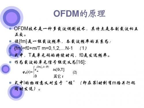
OFDM抗多径衰落原理
在无线传输中,多径衰落信道对通信系统传输带来的 主要影响是符号间干扰( ISI) 和信道间干扰 ( Inter chan2nel Interference ,ICI) 。OFDM 技术 具有良好的抗多径能力,可以克服这两个对通信性能 影响的因素,其原理可描述为:(1) 数据符号在多个 载波上同时传输,各子载波上的数据传输速率是具有 相同系统数据传输速率的单载波传输系统的1/ N ,子 载波上的符号传输时间相应增加为N倍。这样就可 能实现高速率数据传输而同时保证数据符号的持续 时间远大于信道的时延扩展,从而来克服符号间干扰 ( ISI) 。如图1 单载波传输系统与OFDM 系统的 传输比较。图中OFDM 系统分两路传输4 个二进制 码元。
或者,表示为:
其中, H表示N ×( N + v) 的信道矩阵, s , r 分别表 示输入和输出信号的列矩阵, n为加性白色高斯噪声矩 阵。由上式可以看出, 由于多径信道时延扩展所引入的 记忆特性, 使得当前符号块的输出信号{ rk , rk1 , ……, rk- N +1 } 不仅与当前符号块的输入信号{ sk , sk- 1 ,……, sk- N +1 } 有关,而且与当前一符号块的最 后v个输入信号{ sk- N , sk- N - 1 ,……, sk- N - v+1 } 有关,即产生了OFDM 符号块间的干扰(ISI) 。
假设此时传输需要花费4 s 的时间,那么,在图1 左 边的单载波系统中每个码元的码元持续时间是1 s ,而在图1 右边的OFDM 系统中也将同时发送4 个码元。在这样的情况下,每个数据将有4 s 的持 续时间,自然带来的符号间干扰比较小。
图1 单载波传输系统与OFDM 系统的传输比较
ofdm 信道估计 维纳滤波原理
ofdm 信道估计维纳滤波原理
OFDM(Orthogonal Frequency Division Multiplexing)是一种数字调制技术,用于将高速数据信号分割成多个低速子信号,在多个正交频带上同时传输。
由于多径效应和多径衰落等因素的影响,OFDM信号在传输过程中会出现失真和干扰,导致接收端难以正确解码数据。
为了克服这些问题,需要进行信道估计和滤波,以获取更准确的信道状态信息(CSI)。
维纳滤波是一种常用的信号处理技术,用于估计随机过程的均值和方差。
在OFDM系统中,信道估计和滤波的目标是估计出信道的响应函数,即信道的输出信号与输入信号的关系。
维纳滤波的基本思想是,通过对信道的输入和输出信号进行建模,利用已知的输入信号和估计的信道状态信息,计算信道输出信号的最优估计值。
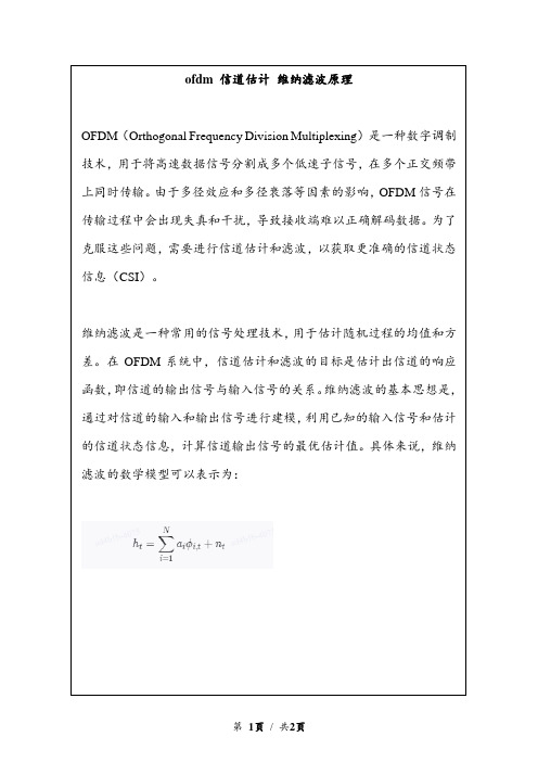
具体来说,维纳滤波的数学模型可以表示为:
维纳滤波器的阶数越高,估计的信道状态信息越准确,但同时也会增加计算复杂度。
因此,在实际应用中,需要根据信道的特性和系统的性能要求来选择合适的滤波器阶数。
ofdm雷达测距原理
有关“OFDM雷达”的测距原理
有关“OFDM雷达”的测距原理如下:
OFDM雷达测距原理主要基于发射信号与接收信号之间的时间差来计算距离。
雷达系统发出OFDM信号,该信号遇到目标后会反射回来,被雷达接收器接收。
通过测量发射信号与接收信号之间的时间差,可以计算出目标与雷达之间的距离。
具体来说,雷达系统会发出具有一定周期的OFDM信号,该信号由多个子载波组成。
当OFDM信号遇到目标时,会有一部分信号反射回来,被雷达接收器接收。
通过对比发射信号与接收信号的差异,可以计算出信号传播的时间,进而根据光速和时间计算出目标与雷达之间的距离。
OFDM雷达测距原理具有较高的精度和抗干扰能力,因此在雷达测距、通信和导航等领域得到了广泛应用。
OFDM调制

OFDM调制OFDM原理OFDM是多载波调制的一种。
其主要思想是:将信道分成若干正交子信道,将高速数据信号转换成并行的低速子数据流,调制到在每个子信道上进行传输。
正交信号可以通过在接收端采用相关技术来分开,这样可以减少子信道间相互干扰ICI 。
每个子信道上的信号带宽小于信道的相关带宽,因此每个子信道上的可以看成平坦性衰落,从而可以消除符号间干扰。
而且由于每个子信道的带宽仅仅是原信道带宽的一小部分,信道均衡变得相对容易。
OFDM的优点1.可以有效地对抗信号波形间的干扰,适用于多径环境和衰落信道中的高速数据传输。
由于OFDM是多载波宽带系统,而当信道中因为多径传输而出现频率选择性衰落时,只有落在频率凹陷处的子载波以及其携带的信息受影响,其他大量的子载波未受损害,因此系统总的误码率性能要好得多。
2.OFDM技术抗窄带干扰性很强,因为这些干扰仅仅影响到很小一部分子信道。
3.多载波的产生、调制与解调,可以用基于IFFT/FFT的方法来实现。
4.频谱利用率很高,当子载波个数很大时,系统的频谱利用率趋于2(b/s)/Hz。
5.由于OFDM技术采用了循环前缀(即在符号有效期前面加入保护间隔),抗码间干扰(ISI)能力很强。
6.很容易实现单频网(SFN),节约频谱,节约功率。
OFDM的缺点1.对子载波之间的正交性有严格的要求,易受频率偏差的影响,正交性收到破坏,会造成子信道间干扰(ICI)。
2.OFDM系统有高的峰值功率/平均值功率比,对A/D或D/A及功率放大器线性有高的要求。
OFDM符号一个OFDM 符号就是经过IFFT 和加CP 之后的符号,因为把高速串行符号变成了低速并行符号,所以其长度(和单载波系统相比)是原来的N 倍,N 是FFT 点数。
导频的作用离散导频:交错排列,用于时频域信道估计。
连续导频:左右对称排列,频率跟踪、相位校正,以及承载72比特系统信息。
子载波间隔的选择OFDM 系统的子载波间隔选择取决于频谱效率和抗频偏能力的折中。
OFDM基本原理

现代社会对通信的依赖和要求越来越高,于是设计和开发效率更高的通信系统成了通信工程界不断追求的目标。
通信系统的效率,说到底是频谱利用率和功率利用率。
特别是在无线通信的情况下,对两个指标的利用率更高,尤其是频谱利用率。
于是,各种各样具有较高频谱效率的通信技术不断被开发出来,OFDM(Orthogonal Frequency Division Multiplexing ,正交频分复用)是一种特殊的多载波调制技术,它利用载波间的正交性进一步提高频谱利用率,而且可以抗窄带干扰和抗多经衰落。
OFDM 通过多个正交的子载波将串行数据并行传输,可以增大码元的宽度,减少单个码元占用的频带,抵抗多径引起的频率选择性衰落,可以有效克服码间串扰,降低系统对均衡技术的要求,是支持未来移动通信,特别是移动多媒体通信的主要技术之一。
1 OFDM 基本原理一个完整的OFDM 系统原理如图1 所示。
OFDM 的基本思想是将串行数据,并行地调制在多个正交的子载波上,这样可以降低每个子载波的码元速率,增大码元的符号周期,提高系统的抗衰落和干扰能力,同时由于每个子载波的正交性,大大提高了频谱的利用率,所以非常适合移动场合中的高速传输。
圉1 OFDM 承疏原理植團在发送端,输入的高比特流通过调制映射产生调制信号, 经过串并转换变成N 条并行的低速子数据流,每 N 个并行数据构成一个 OFDM 符号。
插入导频信号后经快速傅里叶反变换(IFFT)对每个 OFDM 符号的N 个数据进行调制,变成时域信号为:M-Ix<n> = IFFT [X<m)J = ∑Xt■ ■0式中:m 为频域上的离散点;n 为时域上的离散点;N 为载波数 目。
为了在接收端有效抑制码间干扰(InterSymbol Interference ,ISI), 通常要在每一时域 OFDM 符号前加上保护间隔(Guard Interval , Gl)。
加保护间隔后的信号可表示为式(2),最后信号经并/串变换及 D /A 转换,由发送天线发送出去。
正交频分复用(OFDM)原理及相关分析综述
正交频分复用(OFDM)原理及其实现一、OFDM基本原理OFDM是一种无线环境下的高速传输技术,该技术的基本原理是将高速串行数据变换成多路相对低速的并行数据并对不同的载波进行调制。
这种并行传输体制大大扩展了符号的脉冲宽度,提高了抗多径衰落的性能。
传统的频分复用方法中各个子载波的频谱是互不重叠的,需要使用大量的发送滤波器和接受滤波器,这样就大大增加了系统的复杂度和成本。
同时,为了减小各个子载波间的相互串扰,各子载波间必须保持足够的频率间隔,这样会降低系统的频率利用率。
而现代OFDM系统采用数字信号处理技术,各子载波的产生和接收都由数字信号处理算法完成,极大地简化了系统的结构。
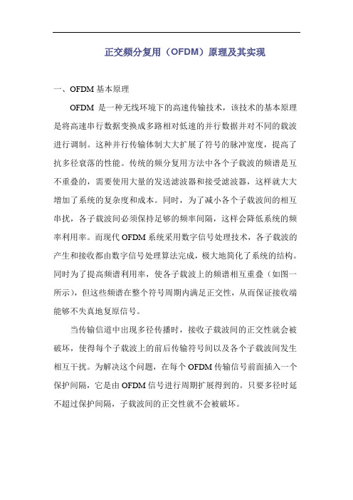
同时为了提高频谱利用率,使各子载波上的频谱相互重叠(如图一所示),但这些频谱在整个符号周期内满足正交性,从而保证接收端能够不失真地复原信号。
当传输信道中出现多径传播时,接收子载波间的正交性就会被破坏,使得每个子载波上的前后传输符号间以及各个子载波间发生相互干扰。
为解决这个问题,在每个OFDM传输信号前面插入一个保护间隔,它是由OFDM信号进行周期扩展得到的。
只要多径时延不超过保护间隔,子载波间的正交性就不会被破坏。
图1 正交频分复用信号的频谱示意图二、OFDM系统的实现由上面的原理分析可知,若要实现OFDM,需要利用一组正交的信号作为子载波。
我们再以码元周期为T的不归零方波作为基带码型,经调制器调制后送入信道传输。
OFDM调制器如图2所示。
要发送的串行二进制数据经过数据编码器形成了M个复数序列,此复数序列经过串并变换器变换后得到码元周期为T的M路并行码,码型选用不归零方波。
用这M路并行码调制M个子载波来实现频分复用。
图2 OFDM调制器在接收端也是由这样一组正交信号在一个码元周期内分别与发送信号进行相关运算实现解调,恢复出原始信号。
OFDM解调器如图3所示。
然而上述方法所需设备非常复杂,当M很大时,需要大量的正弦波发生器,滤波器,调制器和解调器等设备,因此系统非常昂贵。
第3章 OFDM系统原理
升余弦窗函数定义
0.5 0.5 cos( t /( Ts )) w(t ) 1.0 0.5 0.5 cos((t T ) /( T )) s s 0 t Ts
Ts t Ts Ts t (1 )Ts
128子载波、滚降系数分别为0(矩形函数)、0.025、0.05、
方案一 : 选择16QAM和码率为1/2的编码方法。 每个子载波可以携带2bit的有用信息,因此,需要
60个子载波来满足每个符号120bit的传输速率。
方案二 : 利用QPSK和码率为3/4的编码方法。
每个子载波可以携带1.5bit的有用信息,因此需要80个 子载波来传输。 80子载波就意味着带宽为
1 s( f ) N
2
d TSa( ( f f )T
i 0 i i
N 1
2
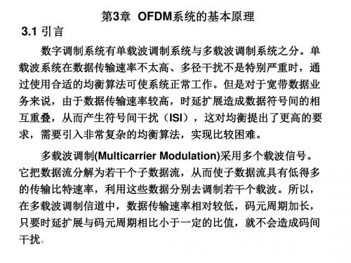
由于OFDM符号每个子载波的功率谱大致呈抽样函数形 状,旁瓣的振荡衰减比较慢,所以导致OFDM符号的整个功 率谱带外辐射比较大 。
OFDM信号的功率谱密度
32个子载波的OFDM信号的功率谱密度
子载波个数为16、64和256的OFDM系统的PSD
t kT / N (k 0,1,, N 1)
2ik sk s(kT / N ) di exp j N i 0
N 1
N 1
0 k N 1
1 x(n) X (k )e N k 0
N 1
jቤተ መጻሕፍቲ ባይዱ
2 nk N
3.3 OFDM的保护间隔和循环前缀
0.1和0.5的升余弦窗函数对OFDM系统功率谱密度的影响
3.5 OFDM的参数选择 在OFDM系统中,需要确定的参数有:符号周期、保 护间隔、子载波的数量。
OFDM技术 原理

实际运用中,常采用IFFT/FFT代替IDFT/DFT进行调制,可 以显著降低运算复杂度。对于N非常大的OFDM,可进一步 用基-4IFFT算法来实施傅里叶变换。
• W1=60*250kHz=15MHz (<18MHz)
– QPSK with R=3/4 CC: n*2*R=120, n=80 – W2=80*250kHz=20MHz (>18MHz)
Signal Bandwidth
• Data bits in each OFDM symbol: 25Mbit / s 100bit
GI, Why?
• With out GI: ISI
OFDM1
OFDM2
OFDM1
OFDM2
GI(续)
为了最大限度的消除码间干扰,在每个符号之间插入保护间隔 (GI),只要保护间隔长度大于信道的最大时延就可以完全消除码 间干扰。这段保护间隔内可以不插任何信号,即为空白传输段。
GI
Data
GI
Data
优点4:高的频谱利用率
FDM
saving spectral
OFDM
Frequency Frequency
优点4:高的频谱利用率
• 传统的单载波系统:
假设M进制调制,单载波,符号周期为T
频带带宽: Bit传输速率:
W
2 T
2Rs
R Rs log 2 M
频谱利用率:
R W
1 2
log
2
M
bit / s / Hz
0 n NTs
OFDM的原理

OFDM的原理OFDM是由欧洲广播联盟采用的用于陆地数字广播传输的技术。
因为广播区域的半径通常达到几百公里,并且具有大的延迟传播特性的频率选择性衰落。
随后提出了OFDM扩频(OFDM SS)通信体制,用于无线LAN和蜂窝系统中抑制码片间干扰(ICI)和码符号间干扰(ISI)。
OFDM信号是由大量在频率上等间隔的载波构成。
载波间隔一般取为符号周期Ts的倒数。
当每个子信道的符号由矩形时间脉冲组成时,每个调制载波的频谱为sinx/x形状,其峰值相应于所有其它载波的频谱中的零点。
OFDM的原理如图1。
如果复用载波信号的数据符号间隔为T S,被分隔的频率差为df=n/T S,这些载波信号必须为正交的。
图1 OFDM原理图设{f k}是一组载波,各载频的关系为:{f k} = f0 + k/Ts k = 1,2,3, ...N-1Ts是单元码的持续时间,f0是发送的频率。
作为载波的单元信号组定义为:其频谱相互交叠,满足正交条件:以及,当以一组取自有限集的复数{C j,k}表示数字信号对调制时,则, 即OFDM信号。
通过下式可以解调:图2 给出OFDM调制解调原理方框图。
图2 OFDM调制解调原理图基带OFDM信号可以表示为:N为载波数;为传输数据;f k为第K个载波的频率,满足f k = k/Ts, 在t=nT时,抽样上述方程的信号为:式子的右边是{C k}复数的IDFT变换的实部,因此,可以在时域采用IDFT获得基带OFDM信号,同理可得基带OFDM信号x g(t) 在时域的抽样值为IDFT输出的虚部。
于是,中频信号为:。
- 1、下载文档前请自行甄别文档内容的完整性,平台不提供额外的编辑、内容补充、找答案等附加服务。
- 2、"仅部分预览"的文档,不可在线预览部分如存在完整性等问题,可反馈申请退款(可完整预览的文档不适用该条件!)。
- 3、如文档侵犯您的权益,请联系客服反馈,我们会尽快为您处理(人工客服工作时间:9:00-18:30)。
The principles of orthogonal frequency division multiplexing (OFDM)modulation have been in existence for several decades.However,in recent years these techniques have quickly moved out of textbooks and research laboratories and into prac-tice in modern communications systems.The tech-niques are employed in data delivery systems over the phone line,digital radio and television,and wireless networking systems.What is OFDM?And why has it recently become so popular?This article will review the fundamentals behind OFDM tech-niques,and also discuss common impairments and how,in some cases,OFDM mitigates their effect.Where applicable,the impairment effects and tech-niques will be compared to those in a single carrier system.A brief overview of some modern applica-tions will conclude the article.The single-carrier modulation systemA typical single-carrier modulation spectrum is shown in Figure 1.A single carrier system modu-lates information onto one carrier using frequency,phase,or amplitude adjustment of the carrier.Fordigital signals,the information is in the form of bits,or collections of bits called symbols,that are modu-lated onto the carrier.As higher bandwidths (data rates)are used,the duration of one bit or symbol of information becomes smaller.The system becomes more susceptible to loss of information from impulse noise,signal reflections and other impairments.These impairments can impede the ability to recover the information sent.In addition,as the bandwidth used by a single carrier system increases,the sus-ceptibility to interference from other continuous sig-nal sources becomes greater.This type of interfer-ence is commonly labeled as carrier wave (CW)or frequency interference.Frequency division multiplexing modulation systemFrequency division multiplexing (FDM)extends the concept of single carrier modulation by using multiple subcarriers within the same single channel.The total data rate to be sent in the channel is divided between the various subcarriers.The data do not have to be divided evenly nor do they have to originate from the same information source.Advantages include using separate modula-tion/demodulation customized to a particular type of data,or sending out banks of dissimilar data that can be best sent using multiple,and possibly dif-ferent,modulation schemes.Current national television systems committee (NTSC)television and FM stereo multiplex are good examples of FDM.FDM offers an advantage over single-carrier modulation in terms of narrowband frequency interference since this interference will only affect one of the frequency subbands.The other subcarriers will not be affected by the interference.Since each subcarrier has a lower information rate,the data symbol periods in a digital system will be longer,adding some additional immunity to impulse noise and reflections.FDM systems usually require a guard band be-tween modulated subcarriers to prevent the spec-trum of one subcarrier from interfering with an-other.These guard bands lower the system’s effective information rate when compared to a single carrier system with similar modulation.Orthogonality and OFDMIf the FDM system above had been able to use a set of subcarriers that were orthogonal to each other,a higher level of spectral efficiency could have been achieved.The guardbands that were necessary to allow individual demodulation of subcarriers in an FDM system would no longer be necessary.The use of orthogonal subcarriers would allow the subcarri-ers’spectra to overlap,thus increasing the spectral efficiency.As long as orthogonality is maintained,it is still possible to recover the individual subcarriers’signals despite their overlapping spectrums.If the dot product of two deterministic signals is equal to zero,these signals are said to be orthogo-nal to each other.Orthogonality can alsobeFigure 1.Single carrier spectrum example.signal processingThe principlesof OFDMMulticarrier modulation techniques are rapidly moving from the textbookto the real world of modern communication systemsBy Louis Litwin andMichael Pugelviewed from the standpoint of stochas-tic processes.If two random processes are uncorrelated,then they are orthogonal.Given the random nature of signals in a communications sys-tem,this probabilistic view of orthogo-nality provides an intuitive under-standing of the implications of orthog-onality in ter in this article,we will discuss how OFDM is imple-mented in practice using the discrete fourier transform (DFT).Recall from signals and systems theory that the sinusoids of the DFT form an orthogo-nal basis set,and a signal in the vec-tor space of the DFT can be represent-ed as a linear combination of the orthogonal sinusoids.One view of the DFT is that the transform essentially correlates its input signal with each of the sinusoidal basis functions.If the input signal has some energy at a cer-tain frequency,there will be a peak in the correlation of the input signal and the basis sinusoid that is at that corre-sponding frequency.This transform is used at the OFDM transmitter to map an input signal onto a set of orthogo-nal subcarriers,i.e.,the orthogonal basis functions of the DFT.Similarly,the transform is used again at the OFDM receiver to process the received subcarriers.The signals from the sub-carriers are then combined to form an estimate of the source signal from the transmitter.The orthogonal and uncorrelated nature of the subcarriers is exploited in OFDM with powerful results.Since the basis functions of the DFT are uncorrelated,the correla-tion performed in the DFT for a given subcarrier only sees energy for that corresponding subcarrier.The energy from other subcarriers does not con-tribute because it is uncorrelated.This separation of signal energy is the rea-son that the OFDM subcarriers’spec-trums can overlap without causing interference.A simple OFDM exampleFigure 3shows a simple representa-tion of an OFDM system.These types of systems have been built but the practicality of such construction quick-ly diminishes as the number of subcar-riers increases.Each subcarrier car-ries one bit of information (N bits total)by its presence or absence in the output spectrum.The frequency of each subcarrier is selected to form an orthogonal signal set,and these fre-quencies are known at the receiver.Note that the output is updated at a periodic interval T that forms the sym-bol period as well as the time bound-ary for orthogonality.Figure 4shows the resultant frequency spectrum.In the frequency domain,the resulting sin function side lobes produce over-lapping spectra.The individual peaks of subbands all line up with the zero crossings of the other subbands.This overlap of spectral energy does not interfere with the system’s ability to recover the original signal.The receiv-er multiplies (i.e.,correlates)the incoming signal by the known set of sinusoids to produce the original set of bits sent.The digital implementation of an OFDM system will enhance these simple principles and permit more complex modulation.Implementation of an OFDM systemThe idea behind the analog imple-mentation of OFDM can be extendedtoFigure 3.A Simple OFDM generator.N subcarri-ers transmitting 1bit of information each,by turning on and off at time intervalsT.Figure 4.Overall spectrum of the simple OFDM signal shown with four subcarriers within.Note that the zero crossings all correspond to peaks of adjacentsubcarriers.Figure 2.FDM signal spectrum example.the digital domain by using the discrete Fourier Transform(DFT)and its coun-terpart,the inverse discrete Fourier Transform(IDFT).These mathematical operations are widely used for trans-forming data between the time-domain and frequency-domain.These trans-forms are interesting from the OFDM perspective because they can be viewed as mapping data onto orthogonal sub-carriers.For example,the IDFT is used to take in frequency-domain data and convert it to time-domain data.In order to perform that operation,the IDFT cor-relates the frequency-domain input data with its orthogonal basis functions, which are sinusoids at certain frequen-cies.This correlation is equivalent to mapping the input data onto the sinu-soidal basis functions.In practice,OFDM systems are implemented using a combination of fast Fourier Transform(FFT)and inverse fast Fourier Transform(IFFT) blocks that are mathematically equiv-alent versions of the DFT and IDFT, respectively,but more efficient to implement.An OFDM system treats the source symbols(e.g.,the QPSK or QAM symbols that would be present in a single carrier system)at the transmitter as though they are in the frequency-domain.These symbols are used as the inputs to an IFFT block that brings the signal into the time-domain.The IFFT takes in N symbols at a time where N is the number of subcarriers in the system.Each of these N input symbols has a symbol period of T seconds.Recall that the basis functions for an IFFT are N orthogonal sinusoids.These sinusoids each have a different frequency and the lowest frequency is DC.Each input symbol acts like a complex weight for the corresponding sinu-soidal basis function.Since the input symbols are complex,the value of the symbol determines both the ampli-tude and phase of the sinusoid forthat subcarrier.The IFFT output isthe summation of all N sinusoids.Thus,the IFFT block provides a sim-ple way to modulate data onto Northogonal subcarriers.The block of Noutput samples from the IFFT makeup a single OFDM symbol.The lengthof the OFDM symbol is NT where T isthe IFFT input symbol period men-tioned above.After some additional processing,the time-domain signal that resultsfrom the IFFT is transmitted acrossthe channel.At the receiver,an FFTblock is used to process the receivedsignal and bring it into the frequency-domain.Ideally,the FFT output willbe the original symbols that weresent to the IFFT at the transmitter.When plotted in the complex plane,the FFT output samples will form aconstellation,such as16-QAM.However,there is no notion of a con-stellation for the time-domain signal.When plotted on the complex plane,the time-domain signal forms a scat-ter plot with no regular shape.Thus,any receiver processing that uses theconcept of a constellation(such assymbol slicing)must occur in the fre-quency-domain.The block diagramin Figure5illustrates the switchbetween frequency-domain and time-domain in an OFDM system.Multipath channels andthe use of cyclic prefixA major problem in most wirelesssystems is the presence of a multipathchannel.In a multipath environment,the transmitted signal reflects off of sev-eral objects.As a result,multipledelayed versions of the transmitted sig-nal arrive at the receiver.The multipleversions of the signal cause the receivedsignal to be distorted.Many wired sys-tems also have a similar problem wherereflections occur due to impedance mis-matches in the transmission line.A multipath channel will cause twoproblems for an OFDM system.Thefirst problem is intersymbol interfer-ence.This problem occurs when thereceived OFDM symbol is distorted bythe previously transmitted OFDM sym-bol.The effect is similar to the inter-symbol interference that occurs in a sin-gle-carrier system.However,in suchsystems,the interference is typicallydue to several other symbols instead ofjust the previous symbol;the symbolperiod in single carrier systems is typi-cally much shorter than the time spanof the channel,whereas the typicalOFDM symbol period is much longerthan the time span of the channel.Thesecond problem is unique to multicarri-er systems and is called IntrasymbolInterference.It is the result of interfer-ence amongst a given OFDM symbol’sown subcarriers.The next sections illus-trate how OFDM deals with these twotypes of interference.Intersymbol interferenceAssume that the time span of thechannel is LCsamples long.Instead of asingle carrier with a data rate of R sym-bols/second,an OFDM system has Nsubcarriers,each with a data rate ofR/N symbols/second.Because the datarate is reduced by a factor of N,theOFDM symbol period is increased by afactor of N.By choosing anappropriateFigure6.Example of intersymbol interference.The green symbol was transmitted first,followed by the blue symbol.value for N,the length of the OFDM symbol becomes longer than the time span of the channel.Because of this configuration,the effect of intersymbol interference is the distortion of the first L C samples of the received OFDM sym-bol.An example of this effect is shown in Figure 6.By noting that only the first few samples of the symbol are distorted,one can consider the use of a guard interval to remove the effect of inter-symbol interference.The guard interval could be a section of all zero samples transmitted in front of each OFDM symbol.Since it does not contain any useful information,the guard interval would be discarded at the receiver.If the length of the guard interval is prop-erly chosen such that it is longer than the time span of the channel,the OFDM symbol itself will not be distort-ed.Thus,by discarding the guard inter-val,the effects of intersymbol interfer-ence are thrown away as well.Intrasymbol interferenceThe guard interval is not used in practical systems because it does not prevent an OFDM symbol from inter-fering with itself.This type of interfer-ence is called intrasymbol interfer-ence.The solution to the problem of intrasymbol interference involves a discrete-time property.Recall that in continuous-time,a convolution in time is equivalent to a multiplication in the frequency-domain.This property is true in discrete-time only if the signalsare of infinite length or if at least one of the signals is periodic over the range of the convolution.It is not prac-tical to have an infinite-length OFDM symbol,however,it is possible to make the OFDM symbol appear periodic.This periodic form is achieved by replacing the guard interval with something known as a cyclic prefix of length L P samples.The cyclic prefix is a replica of the last L P samples of the OFDM symbol where L P >L C .Since it contains redundant information,the cyclic prefix is discarded at the receiv-er.Like the case of the guard interval,this step removes the effects of inter-symbol interference.Because of the way in which the cyclic prefix was formed,the cyclically-extended OFDM symbol now appears periodic when convolved with the channel.An impor-tant result is that the effect of the channel becomes multiplicative.In a digital communications system,the symbols that arrive at the receiver have been convolved with the time-domain channel impulse response of length L C samples.Thus,the effect of the channel is convolutional.In order to undo the effects of the channel,another convolution must be per-formed at the receiver using a time-domain filter known as an equalizer.The length of the equalizer needs to be on the order of the time span of the channel.The equalizer processes sym-bols in order to adapt its response in an attempt to remove the effects of the channel.Such an equalizer can be expensive to implement in hardware and often requires a large number of symbols in order to adapt its response to a good setting.In OFDM,the time-domain signal is still convolved with the channel response.However,the data will ulti-mately be transformed back into the frequency-domain by the FFT in the receiver.Because of the periodic nature of the cyclically-extended OFDM sym-bol,this time-domain convolution will result in the multiplication of the spec-trum of the OFDM signal (i.e.,the fre-quency-domain constellation points)with the frequency response of the channel.The result is that each subcar-rier’s symbol will be multiplied by a complex number equal to the channel’s frequency response at that subcarrier’s frequency.Each received subcarrier experiences a complex gain (amplitude and phase distortion)due to the chan-nel.In order to undo these effects,a fre-quency-domain equalizer is employed.Such an equalizer is much simpler than a time-domain equalizer.The frequen-cy-domain equalizer consists of a sin-gle complex multiplication for each subcarrier.For the simple case of no noise,the ideal value of the equalizer’s response is the inverse of the chan-nel’s frequency response.An example is shown in Figure 7.With such a set-ting,the frequency-domain equalizer would cancel out the multiplicative effect of the channel.Figure 7.Left plot shows the frequency response of a channel,and the right plot shows the corresponding frequency-domain equalizer response.Note that the equalizer response is large when the channel response is small in order to counteract the effect of a channelnull.COFDM:Coded OFDMCoded OFDM,or COFDM,is a term used for a system in which the error control coding and OFDM modulation processes work closely together.An important step in a COFDM system is to interleave and code the bits prior to the IFFT.This step serves the purpose of taking adjacent bits in the source data and spreading them out across multiple subcarriers.One or more sub-carriers may be lost or impaired due to a frequency null,and this loss would cause a contiguous stream of bit errors. Such a burst of errors would typically be hard to correct.The interleaving at the transmitter spreads out the contigu-ous bits such that the bit errors become spaced far apart in time.This spacing makes it easier for the decoder to cor-rect the errors.Another important step in a COFDM system is to use channel information from the equalizer to deter-mine the reliability of the received bits. The values of the equalizer response are used to infer the strength of the received subcarriers.For example,if the equalizer response had a large value at a certain frequency,it would correspond to a frequency null at that point in the channel.The equalizer response would have a large value at that point because it is trying to compensate for the weak received signal.This reliability informa-tion is passed on to the decoding blocks so that they can properly weight the bits when making decoding decisions. In the case of a frequency null,the bits would be marked as“low confidence”and those bits would not be weighted asheavily as bits from a strong subcarrier.COFDM systems are able to achieveexcellent performance on frequency-selective channels because of the com-bined benefits of multicarrier modula-tion and coding.Non-ideal effects in anOFDM systemThis section will examine the effectsof non-idealities in an OFDM system.These effects will include impairmentsand receiver offsets.Because the fouriertransform is a fundamental operation inOFDM,the effects of several offsets canbe intuitively understood by applyingfourier transform theory.Local oscillatorfrequency offsetAt start-up,the local oscillator(LO)frequency at the receiver is typically dif-ferent from the LO frequency at thetransmitter.A carrier tracking loop isused to adjust the receiver’s LO fre-quency in order to match the transmit-ter’s LO frequency as closely as possi-ble.The effect of having an LO frequen-cy offset can be explained by FourierTransform theory.The LO offset can beexpressed mathematically by multiply-ing the received time-domain signal bya complex exponential whose frequencyis equal to the LO offset amount.Recallfrom Fourier Transform theory thatmultiplication by a complex exponentialin time is equivalent to a shift in fre-quency.The LO offset results in a fre-quency shift of the received signal spec-trum.This shift causes a conditioncalled“loss of orthogonality”to occur.The frequency shift causes the OFDMsubcarriers to no longer be orthogonal.The orthogonality of the subcarriers islost because the bins of the FFT will nolonger line up with the peaks of thereceived signal’s since pulses.Theresult is a distortion called inter-bininterference or IBI.IBI occurs whenenergy from one bin spills over intoadjacent bins and this energy distortsthe affected subcarriers.In FourierTransform theory this effect is calledDFT leakage.The left plot of Figure8shows thespectrum of a received OFDM signalwith no LO offset.For the purpose ofclarity,only one non-zero subcarrierwas transmitted.Note that this subcar-rier is not interfering with its adjacentsubcarriers.The spectrum of the non-zero subcarrier actually extends overthe entire range of the FFT,however,due to the orthogonal nature of the sig-nal,the zero-crossings of the spectrumexactly line up with the other FFT bins.The right plot of Figure8shows thereceived spectrum of the same signalwith one non-zero subcarrier,however,in this case there is an LO offset.Thisoffset has resulted in a loss of orthogo-nality,and the zero-crossings of thenon-zero subcarrier’s spectrum nolonger line up with the FFT bins.Theresult is that energy from the non-zerosubcarrier is spread out among all ofthe other subcarriers,with thosesub-Figure8.Received spectrum with one non-zero subcarrier.The left plot is for the case of no LO offset,and the right plot is for the presence of an LO offset.carriers closest to the non-zero subcarri-er receiving the most interference.This simple example was for the case of only one non-zero subcarrier.In a practical system,almost all of the subcarriers would be actively used for transmitting data.A given subcarrier would experi-ence IBI due to energy from all of the other active subcarriers in the system. The central limit theorem states that the sum of a large number of random processes will result in a signal that has a Gaussian distribution.Because of this property,the IBI will manifest itself as additive Gaussian noise,thus lowering the effective SNR of the system.The effect of an LO frequency offset can be corrected by multiplying the sig-nal by a correction factor.The correc-tion factor would be a sinusoid with a frequency that is ideally equal to the amount of the LO frequency offset. Various carrier tracking algorithms exist that can adaptively determine the frequency that will correct for the offset. LO phase offsetIt is also possible to have an LO phase offset,separate from an LO fre-quency offset.The two offsets can occur in conjunction or one or the other can be present by itself.As the name suggests, an LO phase offset occurs when there is a difference between the phase of the LO output and the phase of the received signal.This effect can be represented mathematically by multiplying the time-domain signal by a complex expo-nential with a constant phase.The result is a constant phase rotation for all of the subcarriers in the frequency-domain.The constellation points for each subcarrier experience the same degree of rotation.If the phase rotation is small,the frequency-domain equaliz-er can correct this effect.Each filtercoefficient in a frequency-domain equal-izer multiplies its corresponding subcar-rier by a complex gain(i.e.,amplitudescaling and phase rotation).The equal-izer’s coefficients can be used to correctfor a small phase rotation as long as therotation doesn’t cause the constellationpoints to rotate beyond the symbol deci-sion rger phase rotations arecorrected by a carrier tracking loop.FFT window location offsetAnother non-ideal effect that canoccur in a real-world OFDM system isan FFT window location offset.An N-point FFT at the receiver processes datain blocks of N samples at a time.Ideally,the N samples taken in by theFFT will correspond to the N samples ofa single transmitted OFDM symbol.Inpractice,a correlation is often used witha known preamble sequence located atthe beginning of the transmission.Thiscorrelation operation aids the receiverin synchronizing itself with the receivedsignal’s OFDM symbol boundaries.However,inaccuracies still remain,andthey manifest themselves as an offset inthe FFT window location.The result isthat the N samples sent to the FFT willnot line up exactly with the correspond-ing OFDM symbol.If the offset is verylarge,part of the N samples will be fromone OFDM symbol,and the rest of sam-ples will be from another OFDM sym-bol.Such a situation would result in asevere distortion of the received subcar-rier’s constellations.Fortunately,such alarge offset does not typically occur if arobust synchronization algorithm isused.More likely,an FFT window loca-tion offset of just a few samples willoccur.The presence of the cyclic prefixgives enough headroom to enable asmall offset to be present without tak-ing samples from more than one OFDMsymbol.However,even an offset of justone sample will cause some degree ofdistortion.Again,the effect can beunderstood from Fourier Transformtheory.The offset can be viewed as ashift in time.As long as the FFT win-dow location offset does not gobeyond an OFDM symbol boundary,this shift in time is equivalent to alinearly-increasing phase rotation inthe frequency-domain constellations.Constellations on subcarriers corre-sponding to low frequencies will berotated slightly,whereas constellationson higher-frequency subcarriers willexperience a larger rotation.Theamount of rotation increases linearly asthe subcarrier’s FFT bin locationincreases.Examples of the effects of dif-ferent degrees of FFT window locationoffsets are shown in Figure9.FFT window location offsets are oftencorrected by performing a time-domaincorrelation with a known trainingsequence embedded in the transmittedsignal.The location of the peak of thecorrelation allows the receiver to syn-chronize itself with the incoming signal.Sampling frequency offsetAnother potentially harmful situa-tion is the presence of a sampling fre-quency offset.This condition occurswhen the A/D converter output is sam-pled either too fast or too slow.Recallthat FS/2is the highest available fre-quency in discrete-time where FSis thesampling frequency.Sampling too fastessentially increases the value of FS/2and the result is a contracted(i.e.,squashed)spectrum.Similarly,sam-pling too slow decreases the value of F S /2and results in an expanded spec-trum.If the spectrum expands too much,aliasing of the spectrum can occur.Either type of sampling frequen-cy offset results in IBI since the expan-sion or contraction of the spectrum pre-vents the received subcarriers from lin-ing up with the FFT bin locations.The effect of sampling too fast is illustrated in Figure 10and simulation results to demonstrate this effect are shown in Figure 11.A sampling frequency offset can be corrected by generating an error term that is used to drive a sampling rate converter.Uniform noiseAdditive white Gaussian noise (AWGN)is the most common impair-ment encountered in a communicationssystem.In a wireless medium,the noise source is typically considered to be ther-mal noise that is Gaussian and uniform across the frequency range.Additional noise sources include atmospheric sources and solar radiation.In a con-tained media,such as a coaxial cable system,thermal noise will be present,but the system may also have other sources that can increase the noise in the system.The effect of AWGN on anOFDM system is similar to its effect on a single carrier system.The signal-to-noise ratio (SNR)is a function of the total signal power over the total noise power across the received channel.The uniform noise contributes to the SNR of each subcarrier in the OFDM system and the net result is equivalent to the effect on single channel systems.Non-uniform noiseNoise in a communications channel can often be shaped,or “colored”,by various effects.These effects can include transmit signal imperfections,transmission channel characteristics,or receiver frequency shaping.The impli-cations of these effects for an OFDM system can be different compared to itssingle-carrier counterpart.The modula-tion of the OFDM system can be tai-lored for the noise characteristics.One method previously mentioned involves lowering the modulation (number of bits/symbol)on subcarriers in a low SNR environment as illustrated in Figure 12.Another method involvessending the same data on several sub-carriers,or sending data that can be considered lower priority.In extreme cases,the subcarriers can transmit no data,essentially turning them off.Impulse noiseImpulse noise is a common impair-ment in a communications system aris-ing from motors or lightning.Impulse noise is typically characterized as a short time-domain burst of energy.The burst may be repetitive or may be a sin-gle event.In either case,the frequency spectrum from this energy burst is wideband,typically much wider than the channel,but is present for only a short time period.One of the most important concepts to understand about OFDM and its properties related to the FFT algorithm is how the algorithm changes the nature of the signal.In a single-carrier system,the symbol can be viewed as occupying all of the available frequency spectrum for the time duration of the symbol.A group of symbols then occu-pies all of the spectrum for the duration of the whole group,but in a time divi-sion arrangement.OFDM,using the FFT,takes symbols and creates these groups directly and then transforms them.They are no longer time-domain multiplexed,they are now frequency-domain multiplexed.The OFDM symbol is now a collection of these source symbols,and this OFDM symbol now has a much longer dura-tion.Each original symbol occupies only a small frequency region,but now occu-pies that region for the entire OFDM symbol duration.Figure 13illustrates this concept.For impulses that are short in duration,the impulse energy masks a smaller percentage of time of each OFDM symbol compared to the single carrier case.Impulse noise can therefore have less of an effect on short duration noise.Carrier interferenceSingle-carrier interference arises from other sources that may co-exist in the frequency range of interest.These can be generated by nearby circuits or other transmission sources.The single carrier system must handle this inter-ference as a noise source for all informa-tion sent.The OFDM system can avoid the frequency region of interference by disabling or turning off the affected sub-carriers.Narrowband modulated sources of interference can beconsid-Figure 10.Illustration of the effect of a sampling frequencyoffset.Figure 11.Simulation results showing the effect of a sampling frequency that is too high.Note that the sample that was originally at bin 15is now at bin 8.。
