旁开门系统安装使用说明书
开门器用户操作手册

目录介绍 2-7安全标记和信号词 (2)车库门准备 (3)必需的工具 (4)计划准备 (4)纸箱清单 (7)紧固件清单 (7)装配 8-14装配导轨和滑套 (8)将导轨固定到电机单元上 (9)安装导向滑轮 (10)安装链条/钢丝绳 (11)拉紧链条 (14)安装 15-40重要的安装说明 (15)定位头部支架 (15)安装头部支架.........................................21安装墙壁开关. (28)安装灯泡 (29)安装紧急释放绳和手柄 (30)安装电源 (30)安装保护系统 (31)固定门支架 (34)连接门臂到滑套上 (36)调整 41-43力的调整 (41)门位置的调整 (41)安全反转系统测试 (42)操作 44-51重要安全说明 (44)使用开门器 (45)使用墙壁开关 (46)手动开门 (46)开门器的保养 (47)您有问题吗? (49)将导轨安装到头部支架遥控器编程 52上 (23)固定开门器 (24)悬挂开门器 (26)说明安全标记和信号词本车库门开门机只有严格按照本说明书进行安装,使用,检修与检查才安全可靠。
当你在后面看到这些安全标记和信号词时,他们将警告你如果你不遵守这些警告事项将可能导致严重的伤害或死亡,这些可能是由机械或电所致,仔细阅读警告事项。
当你在后面看到这些信号词时,它将警告你如果不遵守这些注意事项可能会破坏车库门和/或开门器,仔细阅读它们。
车库门准备安装开始前:●去掉锁;●去掉任何连接在车库门上的绳索;●完成以下测试来确定门是否已经被调平衡,以及能否正确的开启和关闭:1、让门停在开启一半的位置,松开手,如果门能够被扭簧支撑而停住,说明门已经调试平衡。
2、开启和关闭门,看是否有卡夹现象如果门被卡住,或没有调试平衡,请打电话给专业安装人员。
必需的工具在开门器的装配、安装和调试过程中,需要图示中的手工具计划准备确定门的类型和重量,测量门的面积,看符合以下那种安装条件,可能需要额外的材料,你会发现这些对你安装开门器是很有用的。
DKC400开门机使用说明书
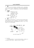
DKC400开门机使用说明书一、概述DKC400开门机专用于平移门的驱动,具有结构紧凑、起动力矩大、能短时超载运行等特点。
过载时,有电气保护,能确保使用安全。
停电时采用专用钥匙脱开离合器实现手动开门、关门。
配套的XF-26型控制箱自带遥控,配接红外线探头时遇障碍物能自动回退。
二、技术指标机械指标:开门机输出轴中心高: 57 mm开门机输出转速:42 rpm整机额定输出力矩:≥18N.m整机空载噪音: ≤60dB电气指标:电源:220V、50Hz额定输入功率:≤300W电机工作制:S4环境参数: 操作温度:-40℃-- +70℃三、安装1、开门机和平移门的安装关系参见图1。
开门机和平移门由图中所示的控制开关控制。
为确保人身和财产安全,须在门体上安装限位开关,以防门体滑出轨道。
从电控箱所在地至主机附近需埋设电线管道,管道内电线的数量为十根,线径应大于1.0mm2。
主机必须用线径1.5mm2 以上铜芯线可靠接地。
平移门大小2.开门机的安装开门机的地基结构参照图2,开门机和门体的位置关系参照图3。
水泥凝固后,把开门机按图标方向放置在安装板上。
调整机器至合适的位置,用螺栓固定。
图2开门机的地基结构图3安装齿条。
1)把固定轴(在齿条包装袋内)焊接在门体上;2) 把齿条固定在固定轴上,调整齿条至合适位置,以便齿条能和齿轮啮合良好并保证0.5mm 的间隙,然后用螺栓紧固。
3) 参照图3安装磁钢开关(磁感应开关的安装是用来控制门体位置的)。
然后,解脱离合器,推动门体至开关位置,以确定安装磁钢开关所需位置。
磁钢固定块和齿条焊接牢固,上紧离合器。
最后,通过电机移动门体来调节磁钢开关至合适的位置。
开关盒距磁钢的位置应在10mm 到15mm 之间,如果距离太大,开关将失灵不工作。
(参见图3)图3开门机和门体的位置关系图4. 控制盒的安装:将电器控制箱安装在室内合适的地方,然后按以下接线图4接线。
为保证新锋开门机使用安全、可靠,本公司特别推荐您选用新锋控制器,其性能与DKC400开门机完全匹配。
蒂森TS-K300轿门系统安装手册

Installation Manual
Version: 1.0
编号:EC305-TS
tk
A Company of ThyssenKrupp
ThyssenKrupp Elevator
蒂森克虏伯电梯 Elevator
Installation Manual
编号:EC305-TS
a) 偏心轮紧压门导轨,门运行阻力过大; b) 门滑块和地坎间的阻力过大; c) 门滑块与地坎槽底部相碰,门板和地坎相碰;
ThyssenKrupp Elevator
11
Installation Manual
编号:EC305-TS
d) 强迫关门弹簧拉力太大; e) 钢丝绳、齿型带过紧,增大了运行阻力。 5.3.2 解决方案 a) 调整偏心轮和门导轨之间的间隙在 0.2~0.5 mm 之间; b) 清洁地坎,纠正门板,调节滑块,使之运行顺畅; c) 调整门板和地坎的间隙为 3~5mm; d) 移动弹簧固定螺栓的位置,减小弹簧力; e) 调整钢丝绳和齿型皮带的松紧度。 f) 若以上调节不能解决,寻求服务。 5.3.3 预防方案或建议 a) 安装时注意阅读操作手册中的细节介绍; b) 安装时,注意检查门机运行阻力。 5.4 门刀没有完全张开导致的开门撞击 a) 故障描述与分析:开门时,门刀没有完全张开,接近开门限位块时,没有经过低速爬行的过 程,于是门在开门到位时出现了撞击。门机开关门时,轿门和厅门完全同步。开门过程中,在门刀带 动厅门板运行之前,门刀首先完全张开,同时打开厅门锁,然后才由齿型带拖动,轿门和厅门同时运 行。齿型带驱动门刀完全张开,需要 7mm 的行程。该案例中,由于门刀没有完全张开,张开门刀的过 程齿形带的行程小于 7mm,导致门实际开到限位时,齿型带还继续拖动门以较快速度运行,所以会出现 开门到位时的撞击。 b) 解决方案:检查并调整可能存在的门刀机构的自身阻力。 参见图 5-1,检查门刀和门锁开启滚轮的配合,调整门锁开滚轮前轮和门刀臂,后轮和刀臂的间 隙均为 11mm. 5.5 厅门锁未闭合导致电梯不运行 5.5.1 故障描述与分析:电梯门关闭后,不走车,检查发现轿门带动厅门关闭时,厅门锁未完全闭 合。安全回路没有闭合,导致电梯不运行。请参见图 5-3。 厅门锁为重力型结构,在正常的情况下,门刀收刀后,都能保持锁的闭合状态。导致厅门锁不能 完全闭合的因素有: a) 触点支架和厅门锁尖口间隙过小,摩擦相碰,导致没有完全闭合; b) 厅门锁主支撑轴不灵活,造成不能正常闭合。 5.5.2 解决方案 a) 调整厅门锁尖口与触点支架的间隙; b) 清洁厅门锁主支撑轴,可加润滑油脂。 5.5.3 预防方案及建议 a) 熟悉操作手册的相关细节; b) 日常保养时注意厅门转轴的灵活性,定期(1 年)在转轴上添加润滑脂。
单双门禁系统安装方法

单双门禁系统安装方法 SANY GROUP system office room 【SANYUA16H-单门、双门、四门系列门禁安装及说明门禁系统分为两种类型,总线和网络型。
总线型分单门、双门、四门等门禁控制器通过485总线方式直接接入门禁服务器串口,前端按钮、电磁锁(电插锁)、读卡器、门磁接入门禁控制器。
网络型分两种方式:1、单门、双门等网络门禁控制器通过网络接入门禁服务器,2、前端按钮、电磁锁(电插锁)、读卡器、门磁先接入门禁控制器然后接入网络门禁控制器,通过网络接入门禁服务器,门禁控制器可接入门的数量及网络门禁控制器可接入门禁控制器的个数根据现场情况而定。
下面介绍门磁、各种锁、按钮、读卡器、防爆门禁、门禁控制器的介绍及安装方法,因门禁的厂家较多,赞只找了一些有代表性的产品,和其他门禁原理相同。
一、门磁1).门磁的功能和原理,门磁在门禁系统中的应用。
门磁是用来检测门是否关闭的一个小型感应器,有很多电锁是带了门磁功能的,建议客户如果门禁系统中用到门磁,最好是采购带门磁功能(门状态反馈功能)的电锁。
如果电锁没有带门磁功能,可以自行选购门磁,门磁大小比一元硬币略大,价格在十几块钱左右。
市面上常见的一款暗装式门磁,不带电线的一端内藏磁铁,带电线的低端内部藏有干簧管等元器件,当磁铁接近时,电线输出闭合信号,当磁铁远离时,两条电线输出开路信号。
不带电线的一端装在门的顶部,带电线的一端装在门框上。
门关好时,两端正好重叠接近。
市面上还有一些门磁是方形的,适用于明装场合,用于门窗上。
2).门磁在门禁系统中的主要作用在于以下几点:在软件实时监控时,可以看到每个门现在的状态是开着的还是关着的。
可以配合门禁控制器启用门被非法闯入(没有刷卡或者按按钮的合法操作,而门被打开了,例如踹开或者撬开)报警。
可以配合门禁控制器启用门长时间未关闭报警。
备注:如果不需要这几个功能的门禁系统,可以不接门磁。
如果需要这几个功能,就将门磁接到控制器的门磁输入点(例如Sen1GND)上,不用区分正负。
申菱双折变频门机--5253开门机 安装说明书1

旁开门系统安装使用说明书(THP131-52/53型)目录1 产品介绍 (1)2 安装与调试 (2)2.1 轿门装置安装 (2)2.2 轿门装置调整 (4)2.3 层门系统安装 (6)2.4 易损件表 (7)3 维护与保养 (8)1产品介绍1.1 技术参数输入电压:AC220V±10% ;变频控制器额定输出功率:400W ;开门距:JJ700—1200mm。
1.2 工作条件海拔高度不超过1000 m温度在-5 °C~ 50 °C之间相对湿度不大于35 %(25 °C时)电压:200 V~250 V,50~60 Hz介质中无爆炸危险,无足以腐蚀金属和破坏绝缘的气体及导电尘埃。
1.3 结构原理THP131-52型是采用同步带传动非同步开门机,变频控制,非同步门刀。
THP131-53型是采用同步带传动同步开门机,变频控制,同步门刀。
上述两种门机电器控制系统一样,采用PLC控制变频器调速,以达到开关门最佳速度曲线。
主要表现在高效率、高可靠性、高功率因素及优良的调速特性、操作简单、启动电流小、机械震动小、保护功能完美、容易实现闭环调节等方面。
两种门机机械结构主要区别在于:52型采用非同步门刀。
开门时轿门先运动,连杆转动门刀凸轮柄,使门刀合拢,夹紧层门门轮,打开层门门锁装置,从而带动层门开门;53型采用同步门刀,其机械设计保证开门先收门刀,夹紧层门门轮,然后带动层门开门,然后张开门刀,脱离层门门轮,在整个开启和关闭过程中使层门与轿门始终保持平齐。
两种产品均采用三角皮带一级减速、同步带传动机构,运动更加平稳。
2安装与调试2.1 轿门装置安装2.1.2 开门机安装:按图1通过横梁安装臂腰孔调节开门机前后距离,使图2中导轨和轿门地坎的水平距离保证55±1mm和94±1㎜,高度方向和地坎保证HH+90±1mm。
上述尺寸须在开门机两侧同时符2.1.3 轿门板安装:按图3 用小封包中M10螺栓组件把门板吊装好, 若门板倾斜可在门板和挂板之间增减垫片直至调整门垂直。
ME-300A使用说明书
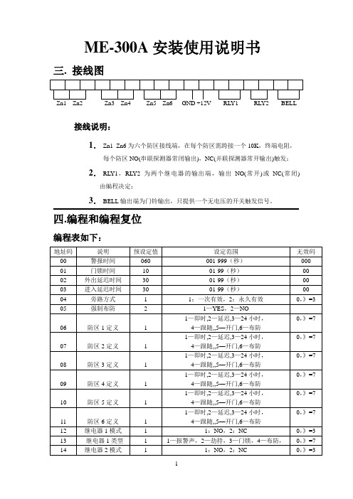
ME-300A安装使用说明书三. 接线图接线说明:1.Zn1_Zn6为六个防区接线端,在每个防区需跨接一个10K,终端电阻,每个防区NO(串联探测器常闭输出),NC(并联探测器常开输出)触发;2.RL Y1,RL Y2为两个继电器的输出端,输出NO(常开)或NC(常闭) 由编程决定;3.BELL输出端为门铃输出,只提供一个无电压的开关触发信号。
四.编程和编程复位编程表如下:系统需在撤防状态1.按“Prog”键;2.输入主码,按“#”键确认(如输入正确,撤/布防灯交替慢闪,提示处于编程地址码输入状态;如输入主码错误,则系统回到正常状态;3.输入编程地址码,按“#”键确认,布/撤防灯交替快闪(提示输入该地址码的编程数据);4.输入该地址码的编程数据,按“#”键确认,如输入正确,系统发出“嘟”的长声并自动跳回地址输入状态(撤防灯交替慢闪);如果输入错误,系统会发出四下短暂的“嘟”声提示无效,保持该地址的原设定值并自动跳回地址输入状态。
地址码00的设定值为三位数;01—03设定值为两位数;04—14设定值为一位数;密码为4—6位数。
5.如输入过程中发现输入错误,可按“*”退回到编程地址码输入状态(撤防灯交替慢闪),重新输入正确的地址码和数据,再按“#”确认;6.退出编程,按“*”键一次或两次,直到撤防灯长亮。
编程步骤摘要:A 按“Prog”键和输入主码,按“#”进入编程(撤防灯交替慢闪);B.输入编程地址码,按“#”键确认(布防灯交替快闪);C.输入编程数据,按“#”键确认(撤防灯交替慢闪);D.按“*”回到编程地址码输入状态或退出编程7.主码恢复:关电源,短路复位跳线,上电后听到连续的提示声,拔掉复位跳线即可。
五. 防盗功能操作1.外出布防:A.输入主码或客码,按“#”确认(如输入的密码正确且无延迟防区,系统立即进入布防状态,撤防灯灭,布防灯亮);B.如果有延迟防区,系统发出延迟声(撤防灯与延迟声同节奏闪动)并在最后15秒声音的速度加快。
开门机使用说明(小控制板)

开门机使用说明(小控制板)-CAL-FENGHAI.-(YICAI)-Company One1自动开门机使用说明书标准技术参数◇机箱材料:国产标准45钢◇传动臂角度:180度◇开门方向:单向◇工作电压: AC220 ±10% V/50 ±10% HZ◇驱动电机:24V 直流有刷电机◇输入接口:干接点信号◇开、关门时间: 1-9秒(可调)◇◇上电后进入通行状态所需时间: 3秒◇◇工作环境:室内、室外(阴棚)◇◇温度:-10℃—— 50℃相对湿度:≤90%,不凝露一、安装说明1、设备的安装:开门机中预埋铺设RVV4X0.75mm2信号线及2X1.5mm2控制线。
并将控制线接至控制室。
用四个膨胀螺丝按下图底座安装尺寸将开门机固定。
设备安装尺寸图2、设备接线安装1)输入接口:OPEN、GND为干接点短路信号;2)接线排的连接:按接线排的标识接好电源和开闸信号;G N D O P E N G N D 磁力锁—磁力锁++12V 21 4 3 6 5控制箱内接线端 电机内光电限位板及接线插座 图3注明:1、提供的开闸信号接法:干接点信号:GND 为公共端,OPEN 和GND 短接就分别开信号;2、将磁力锁的正极(+12V )和负极(GND ),分别接入控制箱内。
3、检查接线是否与接线图一致,检查所有插头是否有松动;检查设备是否接地可靠;确认无误后可上电调试。
3、 注意事项:未经许可,设备上请勿添加外围设备且确保设备接地可靠,保证设备工作的安全可靠;二、设备参数设置操作说明一、通用描述1.显示屏是指主控板上的从左到右显示的2位LED;2.三个按键从左到右依次为INC键,DEC键,SET键,SET键用于进入和退出功能设定;INC键用于对需要设定的参数进行加1;DEC键用于对需要设定的参数进行减1,或退出菜单(显示01时按DEC键退出菜单);当要进入某项功能号时按SET键,此时显示屏显示2位当前功能号参数并闪烁,表示可以用INC键(+),DSC键(—)对此功能号参数进行修改,修改完成后按SET键退出此项参数设置。
单元门口机(VTO12XX系列)_使用说明书_V1.3.0_20040416【智慧安防产品及解决方案】

单元门口机(VTO12XX系列)V1.3.0前言概述本文档详细描述了产品示意图、基本功能介绍、技术参数、设备接口说明、设备安装指导、常见问题。
符号约定在本文档中可能出现下列标志,它们所代表的含义如下。
重要安全须知使用产品前,请认真阅读并严格遵守以下要求,以免您的产品和财产受到损失。
●请在允许的温度和湿度下运输、使用、存储本产品。
●请将产品放置和安装在远离强电、强烈磁场的地方。
●请勿将产品放置在潮湿、有灰尘或煤烟的场所。
●请勿将产品放置在阳光直射的地方或发热源附近。
●请勿随意拆卸本产品。
●请在开启设备上盖或维修设备时断开所有电源,防止触电。
●请使用相同类型的新电池更换旧电池。
●请使用推荐的电源线,并在其额定规格内使用。
特别声明●产品请以实物为准,说明书仅供参考。
●产品实时更新,如有升级不再另行通知。
●最新程序及补充说明文档敬请与公司客服部联系。
●产品说明中有疑问或争议的,以公司最终解释为准。
目录前言 (I)重要安全须知 (II)1 产品概述 (1)1.1型号列表 (1)1.2设备结构 (1)1.2.1 VTO1210A-X/VTO1220A (1)1.2.2 VTO1210B(W)-X/VTO1220B(W) (4)1.2.3 VTO1210C-X (8)2 安装单元门口机 (11)2.1 VTO1220A/VTO1210A-X系列 (11)2.1.1螺钉规格 (11)2.1.2安装步骤 (11)2.1.3线缆连接 (12)2.2 VTO1210B(W)-X/VTO1220B(W)系列 (12)2.2.1螺钉规格 (12)2.2.2安装步骤 (12)2.2.3线缆连接 (13)2.3 VTO1210C-X系列 (13)2.3.1螺钉规格 (13)2.3.2安装步骤 (13)2.3.3线缆连接 (14)3 调测单元门口机 (1)3.1数字系统 (1)3.1.1组网图 (1)3.1.2配置门口机 (1)3.1.3配置数字室内机 (4)3.1.4结果验证 (4)3.2模拟系统 (5)3.2.2配置门口机 (5)3.2.3配置模拟室内机 (7)3.2.4结果验证 (8)4 基本功能 (9)4.1呼叫功能 (9)4.2修改本机配置 (9)4.2.1进入工程设置界面 (9)4.2.2修改IP,网关,子网掩码 (9)4.2.3修改本地音量大小 (9)4.3发卡功能 (9)4.4开锁功能 (10)4.4.1室内机、管理中心远程开锁 (10)4.4.2本地开锁 (10)4.4.3 IC卡开锁 (10)4.5门口机WEB功能 (10)4.5.1登录WEB界面 (10)5 WEB功能介绍 (11)5.1登录 (11)5.2系统设置 (11)5.2.1本机设置 (11)5.2.2联网配置 (13)5.2.3室内机管理 (14)5.2.4分配器管理 (16)5.2.5网络设置 (16)5.2.6视频设置 (16)5.2.7修改密码 (17)5.2.8用户管理 (17)5.2.9 IPC信息 (18)5.2.10公告信息 (19)5.3信息查询 (20)5.3.1通话记录 (20)5.3.2报警记录 (20)5.3.3刷卡记录 (20)5.4状态统计 (21)5.5退出系统 (21)附录1 技术规格 (22)。
SK100电梯旁开自动门系统安装说明书

ThyssenKrupp Elevator A Company of ThyssenKrupp电梯旁开自动门系统安装使用维护说明书(K100,S100)Version:1.0目录第一章适用条件 1 第二章轿门装置安装 1 第三章轿门装置调整 3 第四章层门系统安装 6 第五章安装、调试、维护注意事项8第一章适用条件K100/S100型双折旁开门机是变频传动,轿门、层门同步运行的开门机。
适用于开门宽度JJ700-1200mm乘客电梯。
第二章轿门装置安装2.1 开门机安装: 按图1把开门机直接安装在轿厢上,通过安装座上的腰形孔来调整开门机前后及上下距离,使图2中导轨和轿门地坎的水平距离保证55±1mm和94±1㎜,高度方向和地坎保证HH+90±1mm。
上述尺寸须在开门机两侧同时符合。
层门导轨和地坎高度方向和水平方向的尺寸如图2所示。
(JJ表示净开门宽度、HH 表示净开门高度,以下同)图22.2 轿门板安装:按图3 用小封包中M10螺栓组件把门板吊装好, 若门板倾斜可在门板和挂板之间增减垫片直至调整门垂直。
门板倾斜度及中缝间隙保证在2mm以内。
按图3安装门滑块, 门滑块和门板之间加适量垫片,调整垫片厚度保证快门和慢门平行。
调整后保证快门和轿门地坎前端距离为24mm,快慢门之间间隙为4±1mm,轿门板和轿门地坎间隙为4±1mm。
图33.2可动刀片调整:图6为门关闭状态,关门到位后门刀梁刀片之间的距离为72 mm,门刀中心至挂板边线为125mm,开门时右边的锁紧装置弹簧锁紧凸轮,同时可动刀片合拢至46尺寸,然后可动刀片和挂板同步运动,开门开始。
前后间距应为4±1㎜,具体调整按轿门调整方法。
5.2在现场应做好电气控制的保护工作,避免将异物特别是金属物、屑进入开门机电气控制内部。
5.3电气调试请参阅变频器调试手册。
5.4在驱动轿厢门的电动机轴承应定期加注锂基润滑脂。
ME-300A使用说明书
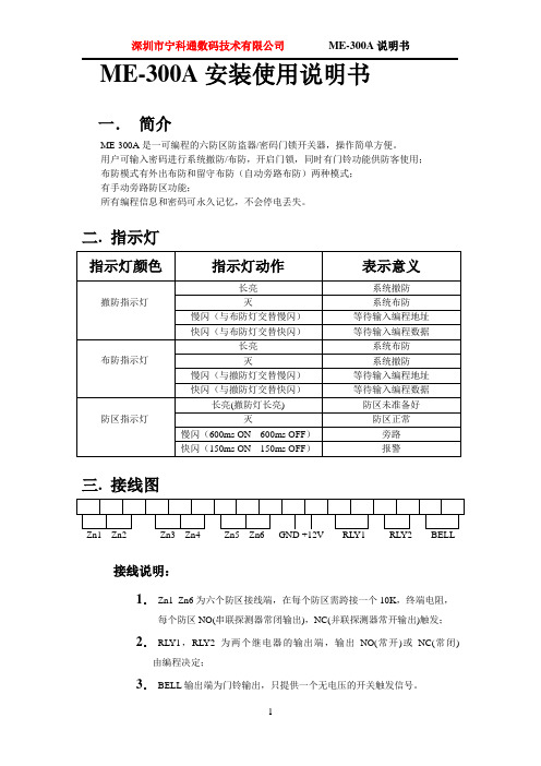
ME-300A安装使用说明书一.简介ME-300A是一可编程的六防区防盗器/密码门锁开关器,操作简单方便。
用户可输入密码进行系统撤防/布防,开启门锁,同时有门铃功能供防客使用;布防模式有外出布防和留守布防(自动旁路布防)两种模式;有手动旁路防区功能;所有编程信息和密码可永久记忆,不会停电丢失。
二. 指示灯三. 接线图接线说明:1.Zn1_Zn6为六个防区接线端,在每个防区需跨接一个10K,终端电阻,每个防区NO(串联探测器常闭输出),NC(并联探测器常开输出)触发;2.RL Y1,RL Y2为两个继电器的输出端,输出NO(常开)或NC(常闭) 由编程决定;3.BELL输出端为门铃输出,只提供一个无电压的开关触发信号。
四.编程和编程复位编程表如下:系统需在撤防状态1.按“Prog”键;2.输入主码,按“#”键确认(如输入正确,撤/布防灯交替慢闪,提示处于编程地址码输入状态;如输入主码错误,则系统回到正常状态;3.输入编程地址码,按“#”键确认,布/撤防灯交替快闪(提示输入该地址码的编程数据);4.输入该地址码的编程数据,按“#”键确认,如输入正确,系统发出“嘟”的长声并自动跳回地址输入状态(撤防灯交替慢闪);如果输入错误,系统会发出四下短暂的“嘟”声提示无效,保持该地址的原设定值并自动跳回地址输入状态。
地址码00的设定值为三位数;01—03设定值为两位数;04—14设定值为一位数;密码为4—6位数。
5.如输入过程中发现输入错误,可按“*”退回到编程地址码输入状态(撤防灯交替慢闪),重新输入正确的地址码和数据,再按“#”确认;6.退出编程,按“*”键一次或两次,直到撤防灯长亮。
编程步骤摘要:A 按“Prog”键和输入主码,按“#”进入编程(撤防灯交替慢闪);B.输入编程地址码,按“#”键确认(布防灯交替快闪);C.输入编程数据,按“#”键确认(撤防灯交替慢闪);D.按“*”回到编程地址码输入状态或退出编程7.主码恢复:关电源,短路复位跳线,上电后听到连续的提示声,拔掉复位跳线即可。
DO3000X门机使用说明

DO3000X 永磁变频门机使用说明书安全注意事项在本手册中,安全注意事项分以下两类:危险:由于没有按要求操作造成的危险,可能导致重伤,甚至死亡的情况注意:由于没有按要求操作造成的危险,可能导致中度伤害或轻伤,及设备损坏的情况请用户在安装、调试和维修本系统时,仔细阅读本章,务必按照本章内容所要求的安全注意事项进行操作。
如出现因违规操作而造成的任何伤害和损失均与本公司无关。
1 安装危险⏹请安装在金属等阻燃的物体上,以避免发生火灾!⏹请勿靠近可燃物品,以避免发生火灾!注意⏹不能让导线头或螺钉掉入其中避免引起控制器损坏!⏹请将控制器安装在震动少,避免阳光直射的地方。
⏹请安装在能耐受其重量的场所,以避免掉落而受伤。
⏹开箱时发现控制器破损时,请不要安装!⏹装箱单与实物名称不符时,请不要安装!⏹搬运时应该轻拿轻放,否则有损害设备的危险!⏹不要用手触及控制器的元器件,否则有静电损坏的危险!2 接线危险⏹必须遵守本手册的指导,由专业电气工程人员施工,以避免触电及伤害事故!⏹控制器和电源之间必须有断路器隔开,否则可能发生火灾!⏹请按标准对控制器进行正确规范接地,否则有触电危险!注意⏹绝不能将输入电源连接到控制器的输出端子(U、V、W)上。
注意接线端子的标记,不要接错线!否则引起控制器损坏!⏹确保所配线路符合EMC要求及所在区域的安全标准。
否则可能发生事故!⏹通讯线必须使用绞线绞距20~30mm的屏蔽双绞线,并且屏蔽层接地!⏹确认产品的额定电压和交流电源的电压一致,以避免发生伤害事故及火灾!⏹注意检查与控制器相连接的外围电路中是否有短路现象;所连线路是否紧固。
否则引起控制器损坏!⏹控制器的任何部分无须进行耐压试验,出厂时产品已作过此项测试。
否则引起事故!3 上电危险⏹控制器必须盖好盖板后才能上电。
上电后不要打开盖板,不要触摸控制器的任何输入输出端子,否则可能引起触电!⏹所有外围配件的接线必须遵守本手册的指导,按照本手册所提供电路连接方法正确接线。
旁开门系统安装使用说明书

旁开门系统安装使用说明书(THP131-52/53型)目录1 产品介绍 (1)2 安装与调试 (2)2.1 轿门装置安装 (2)2.2 轿门装置调整 (4)2.3 层门系统安装 (6)2.4 易损件表 (7)3 维护与保养 (8)THP131-52/53型中分门系统安装使用说明书 1 1产品介绍1.1 技术参数输入电压:AC220V±10% ;变频控制器额定输出功率:400W ;开门距:JJ700—1200mm。
1.2 工作条件海拔高度不超过1000 m温度在-5 °C~ 50 °C之间相对湿度不大于35 %(25 °C时)电压:200 V~250 V,50~60 Hz介质中无爆炸危险,无足以腐蚀金属和破坏绝缘的气体及导电尘埃。
1.3 结构原理THP131-52型是采用同步带传动非同步开门机,变频控制,非同步门刀。
THP131-53型是采用同步带传动同步开门机,变频控制,同步门刀。
上述两种门机电器控制系统一样,采用PLC控制变频器调速,以达到开关门最佳速度曲线。
主要表现在高效率、高可靠性、高功率因素及优良的调速特性、操作简单、启动电流小、机械震动小、保护功能完美、容易实现闭环调节等方面。
两种门机机械结构主要区别在于:52型采用非同步门刀。
开门时轿门先运动,连杆转动门刀凸轮柄,使门刀合拢,夹紧层门门轮,打开层门门锁装置,从而带动层门开门;53型采用同步门刀,其机械设计保证开门先收门刀,夹紧层门门轮,然后带动层门开门,然后张开门刀,脱离层门门轮,在整个开启和关闭过程中使层门与轿门始终保持平齐。
两种产品均采用三角皮带一级减速、同步带传动机构,运动更加平稳。
THP131-52/53型中分门系统安装使用说明书 2 2安装与调试2.1 轿门装置安装2.1.2 开门机安装:按图1通过横梁安装臂腰孔调节开门机前后距离,使图2中导轨和轿门地坎的水平距离保证55±1mm和94±1㎜,高度方向和地坎保证HH+90±1mm。
安全门系统安装说明书
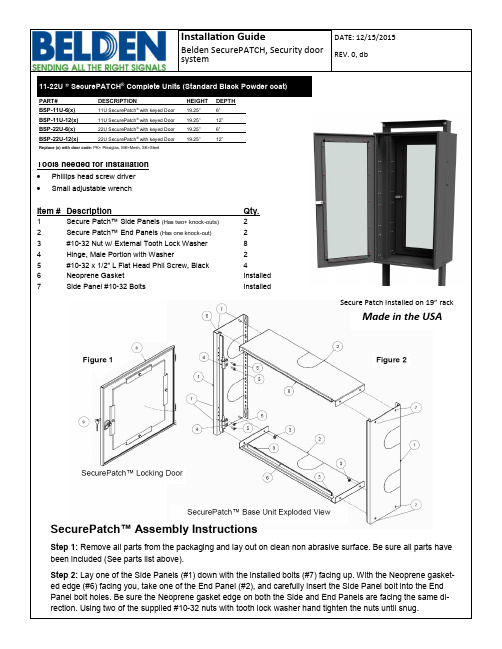
11-22U ” SecurePATCH® Complete Units (Standard Black Powder coat)Secure Patch Installed on 19” rackMade in the USASecurePatch™ Assembly InstructionsStep 1: Remove all parts from the packaging and lay out on clean non abrasive surface. Be sure all parts have been included (See parts list above).Step 2: Lay one of the Side Panels (#1) down with the installed bolts (#7) facing up. With the Neoprene gasket-ed edge (#6) facing you, take one of the End Panel (#2), and carefully insert the Side Panel bolt into the End Panel bolt holes. Be sure the Neoprene gasket edge on both the Side and End Panels are facing the same di-rection. Using two of the supplied #10-32 nuts with tooth lock washer hand tighten the nuts until snug.SecurePatch™ Assembly Instructions, cont...Step 3: With the one End Panel hand tightened, repeat step 2 with the otherEnd Panel on the opposite end of the same Side Panel. Make sure the Neo -prene gasketed edge (#6) is facing the same direction as the previously at -tached Side and End Panel. Using two of the supplied #10-32 nuts with toothlock washer hand tighten the nuts until snug (See Figure 3).Step 4: Lay the remaining side panel on a flat surface, then pick up the 3piece assembly, (2 side and 1 end panel) With the neoprene gasket facingtoward you, tilt the 3 piece assembly toward you and align the side panelholes to the mounting studs on the remaining end panel. Keep the Neoprenegasket edge facing the same direction as the other parts (See Figure 4). Us-ing two of the supplied #10-32 nuts with tooth lock washer hand tighten thenuts until snug.Step 5: With the SecurePATCH™ base unit complete lay the Side Panel withboth End Panels hand tightened down, so that the Neoprene edge is facingup. Once all (8) nuts have been hand tightened with the supplied #10-32 nutswith tooth lock washer tighten the nuts with the adjustable wrench (Do notover tighten!).Step 6: Determine the direction you need the door to swing. Then install the male hinges to the left or right side of the base unit as shown in figure (5).Step 7: Remove all wire management doors or covers from the equipment tobe covered. This is primarily important when using the 6” deep SecurePatch.(this includes but is not limited to doors on fiber boxes) These doors are nolonger needed since the SecurePATCH™ unit will now serve as protection.Also, given the internal clearance, some doors will not open, once inside theSecurePATCH™. Note: If you are installing this unit over existing cable, de-termine at this point if you need to re -move any of the “horse shoe knock -outs”.Step 8: Install two rack screws (not provided) at the top of the rack units to becovered by the SecurePATCH™. Leave them extending, approx. 1/4 to 1/2”.Step 9: Hold the base unit on both side, (without door in -stalled) then “hang”the unit over the exiting equipment. In -stall additional rack screws in bothsides of the Secure -PATCH™ to secure the unit. (minimum 3 screws perside),Step 10: “hang” door on lift off hinged, while extended. Close the door, lock inplace.Note: Each of the side panels have optional accessories available to close offthe open area left in the horseshoe knockouts.Sliding cover plates and brush grommet kits are available. Figure 6。
玛斯特开门机(MST—B60、80、100)用户安装使用手册

——遥控车库门开门机(MST—B60、80、100)用户安装使用手册中美合资大连玛斯特门业有限公司前言欢迎您使用本公司生产的MST—B型遥控自动开门机。
请在安装前务必认真阅读并理解本手册的内容,在未完全理解安装方法前,请不要进行开门机的安装,以免对开门机或门造成不必要的损坏。
目录1、安全操作规程 (1)2、性能特点 (2)3、技术参数 (2)4、安装操作 (3)5、功能设定及调试方法 (3)6、自选功能(配件)连接 (5)7、用户指南 (6)8、开门机及其门的维护 (7)1.安全操作规程1、接通本机电源前,首先检验当地电压应与本机电压相符,超过电压范围要求立即整改,否则会引起开门机破损。
2、安装时,不要穿疏松的衣服,要穿标准的工作服。
3、在位安装完整系统之前,决不允许擅自将开门机电源接通。
4、墙壁开关应安装在可操作范围之内,距离地面高度不小于1.5米,以防儿童接触到;远离门体运动的部件。
5、门的五金件安装一定要牢固,以防运动时松脱,造成门或开门机的损坏。
6、每月均需测试门的平衡系统是否正常,若出现异常,应立即通知专业人员进行调试,以免引起门或开门机的损坏。
7、使用本机前,要确认门的扭簧平衡系统工作正常,门体运行顺畅,无阻滞。
否则,可能会导致开门机或门的损坏。
8、开门机在安装调试完毕后并且无障碍物的情况下才能运行。
门体在运行时,禁止进出车库,禁止儿童在门体附近玩耍。
9、尽可能将开门机安装在距离地面2.5米以上的地方,手动应急手柄要安装在1.5米以上的位置。
10、正确安装完毕并正常运行后,门遇阻力反弹。
11、安装门后,请将本手册放于门附近以便出现故障时参阅维修。
2.性能特点功能特点——单键遥控,实现开门—停止—关门循环动作。
开、关门自动亮灯,3分钟后自动熄灭;直流电机驱动,可柔性启动,运行平稳无噪音;关门遇阻力自动反弹,且反弹力灵敏可靠;遥控器抗干扰性强、距离远、重码率极低、保密性好;安装调试简单,操作方便,使用更安全。
旁通控制器中文说明书(P2P4阀)

3.2 备用电源:24V 直流,在交流电源出现故障后,使用备用电源。
自华
腹有诗书气
3.3 操作气源:0.7Mpa 压缩空气,必须符合气动系统使用要求,如果不能保证气源符合 要求,请务必在气源出口安装气源三联件,过滤精度为 25 微米,通径为 8mm。
3.4 测速传感器:测速传感器为接近开关,响应频率不大于 2KHz,感应距离为 1mm。 3.5 环境温度:-25 ~ 75℃ 3.6 冲击与振动:2~25Hz 振幅 1.6mm; 25~120Hz 加速度 4G。
4. 参数设定
PC2-6 进气系统旁通阀控制器具有参数设定和修改功能。参数设定在远程控制面板上进行。 注意:参数设定必须在控制器通电和柴油机停止工作时进行,或者在确认控制器程序停止
控制后不会对柴油机的运行造成伤害后进行。 注意:参数调整必须由相关专业人员进行。
4.1 喘振速度区域
进 气 压 力
P(
)
ENTER 键确认后出现如下画面,进入 n21 设定画面:
自华
腹有诗书气
注:输入密码并确认后,继续设置其他参数时,将不需要再次输入密码。
按上、下键调整数据,上箭头使数据增加,下箭头使数据减少。调整完毕,按“ENTER”, 确认后闪烁停止。(按键时间越长,增长/减少速度越快),在光标不闪烁的情况下,按下 键,进入如下 n11 设定画面:
按“ESC”键进入如下画面:
自华
腹有诗书气
按上下键选中 Up Speed Area,按 ENTER 键进入如下 n22 设定画面
按上、下键调整数据,上箭头使数据增加,下箭头使数据减少。调整完毕,按“ENTER”, 确认后闪烁停止(按键时间越长,增长/减少速度越快)。在光标不闪烁的情况下,按下键, 进入如下 n12 设定画面:
边门机闸安装说明书

边门机闸安装说明书一、引言边门机闸是一种用于控制人流进出的安全设备,广泛应用于各类场所,如办公楼、购物中心、机场、地铁站等。
本安装说明书旨在指导用户正确安装边门机闸,确保设备的正常运行。
二、安装前的准备工作1. 确定安装位置:根据实际需要,选择适合的位置安装边门机闸。
要保证安装位置的平整、稳固,并且方便人流进出。
2. 安装准备材料:准备好所需安装工具,如螺丝刀、扳手等。
同时,将边门机闸及相关配件准备齐全。
3. 检查设备完整性:在安装前,仔细检查边门机闸及其配件是否完好,并核对清单上的物品是否齐全。
三、安装步骤1. 固定安装底座:根据边门机闸的型号和安装位置,选择合适的安装底座,并将其固定在地面上。
确保底座平整、稳固。
2. 安装边门机闸主体:将边门机闸主体安装在底座上,并使用螺丝刀等工具将其紧固。
在安装过程中,要注意对齐并保持垂直。
3. 连接电源和信号线:根据边门机闸的电源和信号线接口,将其正确连接。
在连接过程中,要注意线路的安全性和稳定性。
4. 调试设备:完成安装后,对边门机闸进行调试。
确保设备能够正常运行,并按照要求进行设置和调整。
5. 进行安全测试:安装完成后,进行边门机闸的安全测试。
测试包括触摸感应、防夹功能等,确保设备符合相关的安全标准。
四、注意事项1. 安装过程中,要确保人员的安全。
在使用电动工具时,要注意电源的安全和绝缘措施。
2. 在安装前,要先阅读产品说明书,了解边门机闸的功能和使用方法。
3. 安装过程中,要遵循厂家提供的操作指南,按照正确的顺序进行操作。
4. 安装完成后,要对设备进行彻底的检查和测试,确保设备符合相关的安全标准和要求。
5. 定期对边门机闸进行维护和保养,清洁设备表面和内部,确保设备的正常运行。
五、常见问题解答1. 问:边门机闸安装过程中需要注意哪些事项?答:安装过程中要确保安装位置平整稳固,正确连接电源和信号线,进行设备的调试和安全测试。
2. 问:边门机闸安装完成后需要注意哪些问题?答:安装完成后要对设备进行彻底的检查和测试,定期进行维护和保养,确保设备的正常运行。
Seiki Vista Screen 右开门安装手册说明书

Vista SCREENInstallation Manual forFor right hinged doorsDurable. Reliable. Attractive.For door openings up to 36” (914mm) wideand 81 3/16” (2,062mm) highQC03-0512RCongratulations and thank you for purchasinga Seiki product!The Vista Screen is designed and manufactured by Seiki Screen Systems, one of Japan's largest and most respected manufacturers.Thanks to rigorous design and product testing,the Vista Screen will provide years of dependable operation.Plus,it comes with a factory-supplied limited lifetime warranty on all parts against manufacturer’s defects.The Vista Screen was designed for easy sizing and installation.This Installation Manual provides a step by step guide through the entire process.We also recommend visiting the Seiki Website at /na to view a short video of a typical installation.Any questions? Contactour Help Line,Toll Freeat 1-877-446-7180.IndexGetting to Know the Vista Screen (4)Parts and Tool List (5)Choosing the Correct Bottom Rail (6)Measuring the Door Opening (7)Sizing the Vista Screen (8)Cutting the Top and Bottom Rail (9)Cutting the Screen Housing (10)Installing the Top Rail (11)Installing the Screen Housing (12)Installing the Bottom Rail (13)Final Steps (14)For installations on double doors (French doors),one leftVista Screen and one right Vista Screen and one DoubleDoor Link Kit will be required.Please refer to theInstallation Manual within the “Double Door Link Kit”prior to installation.The Vista Screen is not intended for installation ona Sliding Patio Door.3Getting to Know the Vista ScreenBefore beginning the installationprocess,become familiar with theVista Screen and the door on which itwill be installed.Make sure the right model has been purchased! The Vista Screen in this package is configured for a “RIGHT”hinged door.To identify door hinging,look at the door from the outside of the house.The hinges should be on the right side and the door knob or handle should be on the left.Next,make sure the Vista Screen will fit the door. The Vista Screen will accommodate a door opening of up to 36”(914 mm) wide and 80 9/16”(2,047mm) high with the Low Rail,and 813/16”(2,062 mm)high with the High Rail.If the door opening is larger than this,the Vista Screen will not accommodate the door.Finally,the Vista Screen requires a minimum mounting surface of 5/8”(16 mm) on top and 11/16”(17 mm) on both sides.This mounting surface must be flat and flush.End Cap RSide BarCushionSide BarWoodScrewMeshWood ScrewEnd Cap LTopRailUpperHousingAssemblyScreenHousingLatchWoodScrewMetalScrewLow Rail orHigh Rail Lower Housing Assemblyminimum5/8"(16 mm)minimum11/16"(17 mm)80 9/16” (2,047 mm)(Low Rail)81 3/16” (2,062 mm)(High Rail)36” (914 mm)45Parts and Tool listLow Rail High Rail Latchfor Bottom RailMetal Screw (4pcs)Stainless Steelfor Side Bar, Top Rail, LatchWood Screw (11pcs)Screen Housing LabelDrill bitTop RailProtective StickerScreen HousingDo not removeuntil installation is complete.Before beginning,make sure that all these parts are included in the Vista Screen package.Side cuttersHack saw 32tpiPhilips screwdriverElectric drillFile Measuring tape LevelCarpenter square Pen Vista Screens can be sized and installed using common household tools.Make sure all necessary tools are available before beginning.*NOTE:a chop saw can be used in place of a hacksaw provided that a bi-metal blade has been properly installed.*Choosing the Correct Bottom RailThe Vista Screen package comes with a Highand Low Bottom Rail to accommodate different configurations of doorsill and exterior trim ordoor frame.Choosing the correct Bottom Railis very important,since this will determinethe final cut size of the Vista Screen.Low RailUse the Low Rail in the following circumstances:1.The front edge of the door sill is flush (A)with theexterior trim or door frame and there is a minimum of9/16”(15 mm) clearance from the top of the sill and thedeck below.2.There is a minimum of 9/16”(15 mm) clearance,but thefront edge of the door sill is recessed (B).Use a shim or an aftermarket sill extension to extend the sill so it isflush with the exterior trim or door frame.High RailUse the High Rail in the following circumstances:1.The door sill is flush with the exterior trim or door frame(A),but there is less than 9/16”(15 mm) clearance to thedeck below.2.The door sill extends beyond the exterior trim (C).3.The door sill has an existing track for a sliding screen (D).Exterior TrimThe height ofthe door sillmin 9/16” (15mm)Door Sill A Exterior TrimThe height ofthe door sillmin 9/16” (15mm)Door Sill BExterior TrimDoor Sill CRail for flatpanel ScreenD67Measuring the DoorOpeningNow it's time to measure the opening to see if the Vista Screen must be cut to fit.For the width,measure the dimension between the right and left exterior trim or door frame at both the top and bottom of the doorway as indicated in the diagram.Record the smallest of the two sizes in the box labeled “Width”below.For the height,measure inside dimension between the top exterior trim or door frame and the door sill at the lowest point in its slope.Measure in all three locations and record the smallest dimension in the box labeled “Height”below.Finally,measure the height of the lowest flat portion of the exterior trim or door frame at the top of the door and record in the box labeled “Top Trim”below.HWTop Trim Mounting SurfaceWidthHeightTop Trim8Sizing theVista ScreenThe Vista Screen is designed to accommodate door openings up to 36”(914 mm) wide and 80 9/16”(2,047 mm) high when using the Low Rail or 81 3/16”(2,062 mm) high when using the High Rail.If the door opening is smaller than this,the Vista Screen must be cut.Determining Cut Size for Top and Bottom RailsTo determine the cut size of the Top and Bottom Rails,simply use the following formula:Determining Cut Size for Screen HousingImportant: The cut size of the Screen Housing is different when using the High Rail versus the Low Rail.Low Rail installations ,use this formula:High Rail installations ,use this formula:NOTE:If the “Length to be cut”is less than 7/16”(11 mm) for either High or Low Rail installations,the Screen Housing may not need to be cut.If the dimension of the “Top Trim”recorded on Page 7 is a minimum of 1 1/16”(27 mm),simply adjust the mounting height of the Top Rail upward.If the exterior trim or door frame is less than this,the Screen Housing must be cut.Determining Mounting Height of Top RailIn all instances when the Screen Housing is cut,the Top Rail is mounted 5/8" (16 mm) above bottom edge of the exterior trim or door frame.If the Screen Housing “Length to be cut”is 7/16”(11 mm) or less,and there is a minimum of 1 1/16”(27 mm) of Top Trim,use the following formula to determine the Mounting Height of the Top Rail .Refer to page 11 for Mounting Suface illustration.(Length to be cut)[Mounting Height]5/8”(16 mm)+ []=(Measured Width)[Length to be cut off]36”(914mm)– [] =(Measured Height)[Length to be cut off]80 9/16”(2047 mm)– [] =(Measured Height)[Length to be cut off]81 3/16”(2062 mm)– [] =9Cutting the Top and BottomRailCutting the Top Rail of the Vista Screen is an easy process.NOTE:The Top Rail will be cut on the end opposite the Tension Gear Bracket .The Top Rail is clearly labeled with CUT and NO CUT zones.1.Remove the End Cap from the side of the Top Rail that will be cut.ing the “Length to be cut”dimension calculated on Page 8,carefully measure and mark the rail on all sides to ensure an even cut.3.Wearing safety glasses,cut straight through the Top Rail using either a chop saw or a hacksaw with a bi-metal blade.Top Rail Protective StickerAdhere Protective Sticker to back edge (closest to door) of the cut end of the Top Rail.Cutting the Bottom RailCutting the Bottom Rail is just as easy.The Bottom Rail is clearly labeled with CUT and NO CUT ing the same “Length to be cut”dimension used for the Top Rail,measure and mark the rail,and cut straight through.NOTE:After cutting any part of the Vista Screen,use a file to remove any burrs from the surfaces.Tension Gear BracketThe uncut end.Cut this end.Door openingCut this portionLow RailCut this portionHigh RailProtective Sticker10Cutting theScreen HousingIt is easy to cut right through the Screen Housing and fiberglass mesh of the Vista Screen using a chop saw or hacksaw.NOTE:All cutting will be done on the lower end of the Screen Housing,away from the Upper Housing Assembly and spring mechanism.The Vista Screen is clearly labeled with CUT and NO CUT zones.1.Begin by tightening the screw at the top of the Upper Housing Assembly (A).2.Remove the Lower Housing Assembly and washer by removing the two screws with a Philips screwdriver (B).3.Slide the Side Bar Cushion off of the Side Bar (C).4.Slide the Bottom Rail Guide off the Screen Housing (D).5.Carefully measure and mark the Screen Housing on all sides based on the “Length to be cut”dimension calculated on Page 8.6.Wearing safety glasses,cut straight through the Screen Housing and the fiberglass mesh (E).7.Before reattaching the Lower Housing Assembly,replace the Side Bar Cushion onto the Side Bar (C).Make sure that it is pushed in as far as it will go.Next,slide the Bottom Rail Guide back onto the Screen Housing (D).8.Reattach the Lower Housing Assembly and washer using the two screws (B).9.Loosen the screw at the top of the Upper Housing Assembly until the head of the screw is slightly above the top (A).10.Finally,remove the black tape,slide the Handle to thecentre of the Screen Housing and tighten the screws (F).ABDEFWasher.Upper Housing AssemblyLower Housing AssemblySide BarSide Bar Cushion Side BarSide Bar CushionSide Bar CushionSide BarHandle Lower Housing AssemblyBottom Rail GuideWasher.Insure that the SIDE BAR CUSHION is pushed completelyin place.CImportantCut this portionCut only from bottom as indicated by hack saw illustration.Do not remove until installation is complete.Removethe black tape.Centre and tighten handle11Installing theTop RailNow it's time to determine the height at which the Top Rail should be mounted.If the Screen Housing Was Cut:If the Vista Screen Housing was cut to fit the door,the top of the Top Rail will be mounted exactly 5/8”(16 mm) (A) from the bottom edge of the exterior trim or door frame.1.Draw a line 5/8”(16 mm) from the bottom edge of the exterior trim or door frame as a guide.2.Remove the backing on the adhesive strip and position the Top Rail along the guide line.3.Secure the Top Rail using the Wood Screws provided.If the Screen Housing Was Not Cuting the measurement calculated for Mounting Height on Page 8(A),measure up from the bottom of the exterior trim or door frame,and draw a line as a guide.2.Remove the backing on the adhesive strip and position the Top Rail along the guide line.3.Secure the Top Rail using the Wood Screws provided.AMounting SurfaceProtective Sticker must be applied to the back edge of the Top Rail after cutting has been completedof12Installing theScreen HousingUpper Housing AssemblySide BarSide Bar Cushion E x t er i o rT r i mSide Bar Cushion must be positioned flush and square to the Top RailSide Bar Cushion must be positioned level with the Upper Housing AssemblyWood Screw [for Side Bar]A1.Remove the End Cap from the right side of the Top Rail.2.Insert the rollers of the Screen Housing into the Top Rail.3.Next,peel the backing off the adhesive strip along the back of the Side Bar.4.Making sure the top of the Side Bar Cushion is level with the Upper Housing Assembly,fasten theSide Bar Cushion to the exterior trim or door frame using a Wood Screw.5.Press the Side Bar firmly in place alongthe exterior trim or door frame,making sure that the fiberglass mesh is kept flat,and the Side Bar is square to the Top Rail.6.Using the provided Wood Screws,secure the Side Bar to the exterior trim or door frame.NOTE: If during the sizing of the Screen Housing,the predrilled hole for the Bottom Side Bar Cushion was removed,a new hole must be drilled (A).13Installing theBottom Rail1.Remove the adhesive backing from the Bottom Rail.2.While slightly lifting the Bottom Rail Guide on the Screen Housing,insert the Bottom Rail.3.Press the Bottom Rail firmly in place,ensuring the front of the rail is flush with the exterior trim or door frame.This requirement is the samewhether using the Low or High Rail.Rail must be placed tight to left side of door frame to ensure that there is a 1/4”(6mm) gap between the right side of the Bottom Rail and the right door frame.4.As a guide,use the predrilled holes in the Bottom Rail to drill holes through the door sill with drill bit provided.(A)5.Fasten theBottom Rail to the door sill using the Metal Screws provided.(B)ScreenHousingBottom Rail Guide The backing of the adhesive stripLift.InsertLow Rail or High Rail Important While lifting the BOTTOM RAIL GUIDE slightly, insertthe BOTTOM RAIL into it.The installation function is the same for either LOW & HIGH RAIL.D o o r S i l lMetal Screw (stainless)[for Bottom Rail]Screen Housing Low Rail or High RailBAA. Door Sill flush with Exterior TrimC. Door Sill extends beyond Exterior TrimD. Door Sill with Existing Screen TracksB. Door Sill recessed from Exterior TrimExterior TrimExterior TrimExterior TrimExterior TrimLow RailHigh RailHigh RailExisting Screen TracksLow Rail Door Sill orConcrete SurfaceDoor Sill orConcrete SurfaceDoor SillDoor SillMin. 9/16” (15 mm)Front edge of High Rail positioned flush with Exterior Trim.Front edge of High Rail positioned flush with Exterior Trim.Front edge of Low Rail positioned flush with Exterior Trim.Shim can be inserted between Door Sill and Low Rail for added support. Shim not included.Min. 9/16” (15 mm)Front edge of Low Rail attached flush with Door Sill.Positioning the Bottom Rail14FinalStepsInstall the End Caps1.Locate the two End Caps removed from the Top Rail during earlier installation steps.2.Press the End Caps firmly into place on both ends of the Top Rail.(A)Install the Latch1.Locate a point 4”(100 mm) below the centre of the door opening on the left exterior trim or door frame.2.Using the Wood Screws provided,fasten the Latch to the inner edge of the exterior trim or door frame.(B)Apply Screen Housing LabelAdhere the “AR”Label to the Screen Housing at the same height as the Latch.(C)Clean up the Lower Housing Assembly1.Locate the Lower Housing Assembly.2.Cut the unused portion of the assembly using side cutters as indicated.(D)The Vista Screen Installationis Now Complete!LatchWood Screw [for Latch]End Cap REnd Cap LPush firmly in place.TOP RAIL4"(100mm)ALatchE x t e r i or T r i mWood Screw [for Latch]The LATCH should be fixed to the inside corner of the exterior trim.BCScreen Housing LabelScreen Housing LatchLower Housing AssemblySide cutters.Pull screen to the closed position, to confirm the Latch and Label are in the correct location.Cut the unused portion of the LOWER HOUSING ASSEMBLY with side cutters where indicated.D15HelpHotlineThe Vista Screen was designed for easy sizing and installation.This installation Manual provides a step by step guide through the entire process.If there are any questions during the installation of the Vista Screen,we recommend visiting the Seiki Website at /na .Seiki provides a number of online manuals on:•Product Information •Vista Screen Installation •Resetting the Vista Screen Spring •Identifying Common Installation ProceduresPlus,Seiki provides online How To Videos on the following topics:•Vista Screen Installation •Right Hinged Application •Re-setting the Spring•Sill and Exterior Trim Assessment•Converting the Vista Screen for Left Hinged DoorsStill Have Questions?Call the Toll Free Seiki Do it Yourself Hotline:1-877-446-7180Vista ScreenLimited Lifetime/Non-transferable Manufacturers WarrantyThe Vista Screen is warranted by Seiki Screen Systems to be free of manufacturers’defects in materials or workmanship,for as long as the original purchaser owns and or resides at that residence and that the product remains at its original point of installation.Seiki Screen Systems will repair or replace at its discretion any component, within the terms and conditions of this warranty,which is deemed as being defective from the manufacturing process upon proof of purchase.This warranty excludes the fiberglass screen mesh.Furthermore this warranty does not cover components damaged through improper use or installation,or if components have been altered from their original state in a manner not otherwise prescribed in this manual.This warranty is strictly limited to defective components only.This non-transferable,limited warranty excludes labor,breakage or damage due to normal wear and tear,lack of maintenance,or use for other than residential applications,accidents and “acts of god”.Replacements or repairs made subject to this limited warranty are otherwise warranted for the balance of the original warranty period.Seiki Screen System’s liability under this limited warranty is restricted to the corrective actions as set forth herein and contrarily repudiates all incidental and consequential damage.It is the responsibility of the consumer to notify Seiki Screen Systems of missing components, within 30 days of the purchase of the Vista Screen.The Vista Screen is designed to assist in keeping unwanted insects from the home; it is in no way intended as a safety or security device to prevent access by individuals, animalsor small children.Liability for any damages,including but not limited to general,special,indirect,incidental,consequential,aggravated,punitive or exemplary damages,and economic loss,as well as for breach of any expressed or implied warranties,including but not limited to implied warranties of merchantability,quality and fitness for any purpose other than as prescribed herein,is disavowed and omitted here from,to the extent that such a disclaimer and preclusions are permitted by the laws of any particular jurisdiction.Maintenance:Keep Bottom Rail clean and free of debris.Periodic use of silicone spray on the rollers of the Upper Housing Assembly and the Bottom Rail guide is recommended; do not use petroleum-based lubricants.Vista ScreenManufactured bySeiki Screen SystemsINSTALLATION INSTRUCTION MANUALFor warranty claimsCall 1-877-446-7180Or email:***************************For maintenance and helpful hints,please refer to our web site,/na。
开门提示器操作方法
开门提示器操作方法开门提示器是一种用于提醒门外人员的设备,它能够向门外发出声音或光线信号,通知门内的人开门。
下面我将详细介绍开门提示器的操作方法。
操作开门提示器有以下几个步骤:1. 安装:首先,你需要选择一个合适的位置来安装开门提示器。
通常,开门提示器应该安装在门的旁边,以便门外的人员能够清楚地看到或听到提示信号。
确保开门提示器与电源连接,并且安装牢固。
2. 设置信号方式:开门提示器通常有多种信号方式可供选择,包括声音和光线。
你可以根据需要选择合适的方式。
在设置信号方式时,你需要按照说明书上的方法进行操作,通常是通过按下设备上的按钮或旋钮来选择信号方式。
3. 设置触发条件:开门提示器一般具有不同的触发条件,如按键、体感、声音等。
你可以根据需要选择适合的触发条件,并进行相应的设置。
一般来说,你需要按下触发器按钮或在设备上设置触发条件,如设置声音敏感度等。
4. 调整音量或亮度:如果你选择了声音信号或光线信号,你可能需要调整音量或亮度来适应不同环境下的使用情况。
在调整音量或亮度时,你需要按照说明书上的方法进行操作,如通过旋钮或按钮来调整相应参数。
5. 测试功能:在完成设置后,你需要测试开门提示器的功能是否正常。
你可以选择一种触发条件,并确认开门提示器是否按照设置的方式发出信号。
如果发现有问题,你可以重新检查设置并进行调整。
6. 维护和保养:开门提示器在使用过程中需要定期进行维护和保养,以确保其正常工作。
你可以定期清理设备,并检查连接线是否稳固。
如果发现任何问题,你应该及时修复或更换部件。
总结起来,操作开门提示器包括安装设备、设置信号方式、设置触发条件、调整音量或亮度、测试功能以及维护和保养。
通过按照说明书上的方法进行操作,你可以轻松地使用开门提示器,提高门禁系统的安全性和便利性。
- 1、下载文档前请自行甄别文档内容的完整性,平台不提供额外的编辑、内容补充、找答案等附加服务。
- 2、"仅部分预览"的文档,不可在线预览部分如存在完整性等问题,可反馈申请退款(可完整预览的文档不适用该条件!)。
- 3、如文档侵犯您的权益,请联系客服反馈,我们会尽快为您处理(人工客服工作时间:9:00-18:30)。
旁开门系统安装使用说明书
(THP131-52/53型)
目录
1 产品介绍 (1)
2 安装与调试 (2)
2.1 轿门装置安装 (2)
2.2 轿门装置调整 (4)
2.3 层门系统安装 (6)
2.4 易损件表 (7)
3 维护与保养 (8)
THP131-52/53型中分门系统安装使用说明书 1 1产品介绍
1.1 技术参数
输入电压:AC220V±10% ;变频控制器额定输出功率:400W ;开门距:JJ700—1200mm。
1.2 工作条件
海拔高度不超过1000 m
温度在-5 °C~ 50 °C之间
相对湿度不大于35 %(25 °C时)
电压:200 V~250 V,50~60 Hz
介质中无爆炸危险,无足以腐蚀金属和破坏绝缘的气体及导电尘埃。
1.3 结构原理
THP131-52型是采用同步带传动非同步开门机,变频控制,非同步门刀。
THP131-53型是采用同步带传动同步开门机,变频控制,同步门刀。
上述两种门机电器控制系统一样,采用PLC控制变频器调速,以达到开关门最佳速度曲线。
主要表现在高效率、高可靠性、高功率因素及优良的调速特性、操作简单、启动电流小、机械震动小、保护功能完美、容易实现闭环调节等方面。
两种门机机械结构主要区别在于:52型采用非同步门刀。
开门时轿门先运动,连杆转动门刀凸轮柄,使门刀合拢,夹紧层门门轮,打开层门门锁装置,从而带动层门开门;53型采用同步门刀,其机械设计保证开门先收门刀,夹紧层门门轮,然后带动层门开门,然后张开门刀,脱离层门门轮,在整个开启和关
闭过程中使层门与轿门始终保持平齐。
两种产品均采用三角皮带一级减速、同步带传动机构,运动更加平稳。
THP131-52/53型中分门系统安装使用说明书 2 2安装与调试
2.1 轿门装置安装
2.1.2 开门机安装:按图1通过横梁安装臂腰孔调节开门机前后距离,使图2中导轨和轿门地坎的水平距离保证55±1mm和94±1㎜,高度方向和地坎保证HH+90±1mm。
上述尺寸须在开门机两侧同时符合。
层门导轨和地坎高度方向和水平方向的尺寸如图2所示。
图2
2.1.3 轿门板安装:按图3 用小封包中M10螺栓组件把门板吊装好, 若门板倾斜可在门板和挂板之间THP131-52/53型中分门系统安装使用说明书 3 增减垫片直至调整门垂直。
门板倾斜度及中缝间隙保证在2mm以内。
按图4安装门滑块,门滑块和门板之间加适量垫片,调整垫片厚度保证快门和慢门平行。
调整后保证快门和轿门地坎前端距离为24mm,快慢门之间间隙为4±1mm,轿门板和轿门地坎间隙为5±1mm。
2.1.4 门刀安装: 52型按图5在轿门快门板上安装门刀,用螺栓将门刀曲柄与连杆连接,连杆另一端与上坎架侧板连接,并调整至图示要求;53型的同步门刀用标准件与快门挂板连接。
门刀伸出轿门地坎尺寸:按图6检查门刀伸出量,如达不到则调整门板和门刀安装板之间加垫片,直至符合要求为止。
图6 图7
2.2 轿门装置调整
产品在出厂前已调整,但考虑到安装搬运影响到尺寸精度,下述几方面在现场仍须调整:
2.2.3 关门行程尺寸:关门到位时两挂板之间距离为40mm,如果达不到微调挂板上钢丝绳组件螺杆长。
