CC6-0505SF-E中文资料
EE-SF5中文资料(omron)中文数据手册「EasyDatasheet - 矽搜」

Sensing object: White paper
(μA)
with a reflection factor of 90%
L
光电流I
间距d(毫米) 感应角度特性 (典型值)
(%)
L
相对光电流I
Ta = 25°C I F = 20 mA V CE = 10 V
Sensing object: W hite paper with a reflec tion fac tor of 90%
IF = 40 mA IF = 30 mA
光电流I
IF = 20 mA IF = 10 mA
集电极 - 发射极
响应时间与负载 阻力特性 (典型值)
电压V CE (V)
VCC = 5 V Ta = 25°C
响应时间TR,TF(微秒)
周围温度Ta(℃)
检测距离特点 (典型值)
Ta = 25°C VCE = 10 V
微型光电传感器(反射)
EE-SF5(-B)与集电极 耗散温度额定值
(mA)
F
正向电流I
光电流与正向电流 特性(典型)
(mW) (μA)
C L
Ta = 25°C VCE = 10 V d = 5 mm Sensing object: White paper with a reflection factor of 90%
d1
相对光电流I
d1 = 5 mm
距离d 感应角度特性 (典型值)
(%)
L
2 (毫米)
距离d
响应时间测量 电路
2 (毫米)
Input
90 %
Output
10 %
相对光电流I
Sensing object
CC-E系列1 CC-E系列超紧凑型1.5W至25W单双路DC-DC转换器说明书
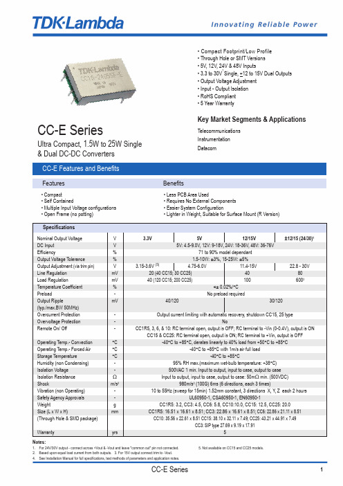
CC-E SeriesUltra Compact, 1.5W to 25W Single & Dual DC-DC ConvertersKey Market Segments & ApplicationsTelecommunications Instrumentation Datacom• Compact Footprint/Low Profile • Through Hole or SMT Versions • 5V, 12V, 24V & 48V Inputs• 3.3 to 30V 1Single, +12 to 15V Dual Outputs • Output Voltage Adjustment • Input - Output Isolation • RoHS Compliant • 5 Year WarrantyCC-E Features and BenefitsFeaturesBenefits• Compact• Less PCB Area Used• Self Contained• Requires No External Components • Multiple Input Voltage configurations • Easier System Configuration• Open Frame (no potting)• Lighter in Weight, Suitable for Surface Mount (R Version)SpecificationsNotes:1.For 24V/30V output - connect across +Vout & -Vout and leave "common out" pin not connected. 5. Not available on CC15 and CC25 models.2.Based upon equal load current from both outputs.3. For 15V output connect trim to -Vout.4.See Installation Manual for full specifications, test methods of parameters and application notes.Nominal Output Voltage V 3.3V5V 12/15V ±12/15 (24/30)1DC Input V 5V: 4.5-9.0V, 12V: 9-18V, 24V: 18-36V, 48V: 36-76VEfficiency%71 to 90% model dependant Output Voltage Tolerance % 1.5-10W: ±3%, 15-25W: ±5%Output Adjustment (via trim pin)V 3.15-3.6V (5) 4.75-6.0V 11.4-15V 22.8 - 30VLine Regulation mV 20 (40 CC15; 30 CC25)4080Load RegulationmV 40 (120 CC15; 200 CC25)1006002Temperature Coefficient %<± 0.02%/°C Preload-No preload requiredOutput RipplemV 40/12030/120(typ./max.BW 50MHz)Overcurrent Protection -Output current limiting with automatic recovery, shutdown CC15, 25 typeOvervoltage Protection -NoRemote On/ Off-CC1R5, 3, 6, & 10: RC terminal open, output is OFF; RC terminal to -Vin (0-0.4V), output is ONCC15 & CC25: RC terminal open, output is ON; RC terminal to +Vin, output is OFFOperating Temp.- Convection °C -40°C to +85°C, derates linearly to 40% load from +50°C to +85°COperating Temp.- Forced Air °C -40°C to +85°C with 1m/s air full loadStorage Temperature°C -40°C to +85°CHumidity (non Condensing)-95% RH max.(maximum wet-bulb temperature: +38°C)Isolation Voltage -500VAC 1 min. Input to output, input to case, output to case Isolation Resistance ΩInput to output, input to case, output to case: 50m Ωmin. (500VDC)Shockm/s 2980m/s 2(100G) 6ms (6 directions, each 3 times)Vibration (non Operating)-10 to 55Hz (sweep for 15min) 1.52mm constant, 3 directions X, Y, Z each 2 hoursSafety Agency Approvals -UL60950-1, CSA60950-1, EN60950-1Weightg CC1R5: 3.2, CC3: 4.5, CC6: 5.8, CC10:10.0, CC15: 12.5, CC25: 20.0Size (L x W x H)mmCC1R5: 16.51 x 16.61 x 8.51; CC3: 22.86 x 16.61 x 8.51; CC6: 22.86 x 21.11 x 8.51(Through Hole & SMD package)CC10: 35.56 x 22.61 x 8.51 CC15: 38.10 x 32.11 x 7.49; CC25: 43.21 x 44.91 x 7.49CC3: SIP type 27.69 x 9.19 x 17.91Warranty yrs5Model SelectorOutput Output OutputVoltage (V)Current (A)Power (W)5V Input12V Input24V Input48V Input Single Outputs3.30.4 1.5CC1R5-0503SF-E CC1R5-1203SF-E CC1R5-2403SF-E CC1R5-4803SF-E3.30.83CC3-0503SF-E CC3-1203SF-E CC3-2403SF-E CC3-4803SF-E3.3 1.26CC6-0503SF-E CC6-1203SF-E CC6-2403SF-E CC6-4803SF-E3.3 2.510CC10-0503SF-E CC10-1203SF-E CC10-2403SF-E CC10-4803SF-E3.34.515--CC15-2403SF-E-3.37.525--CC25-2403SF-E-50.3 1.5CC1R5-0505SF-E CC1R5-1205SF-E CC1R5-2405SF-E CC1R5-4805SF-E50.63CC3-0505SF-E CC3-1205SF-E CC3-2405SF-E CC3-4805SF-E5 1.05CC6-0505SF-E---5 1.26-CC6-1205SF-E CC6-2405SF-E CC6-4805SF-E5 2.010CC10-0505SF-E CC10-1205SF-E CC10-2405SF-E CC10-4805SF-E5 3.015--CC15-2405SF-E-5 5.025--CC25-2405SF-E-12(15)0.125(0.1) 1.5CC1R5-0512SF-E CC1R5-1212SF-E CC1R5-2412SF-E CC1R5-4812SF-E 12(15)0.25(0.2)3CC3-0512SF-E CC3-1212SF-E CC3-2412SF-E CC3-4812SF-E 12(15)0.5(0.4)6CC6-0512SF-E CC6-1212SF-E CC6-2412SF-E CC6-4812SF-E 12(15)0.8(0.64)10CC10-0512SF-E---12(15) 1.0(0.8)10-CC10-1212SF-E CC10-2412SF-E CC10-4812SF-E Dual Outputs±12 (15)30.06(0.05) 1.5CC1R5-0512DF-E CC1R5-1212DF-E CC1R5-2412DF-E CC1R5-4812DF-E ±12 (15)30.125(0.1)3CC3-0512DF-E CC3-1212DF-E CC3-2412DF-E CC3-4812DF-E ±12 (15)30.25(0.2)6CC6-0512DF-E CC6-1212DF-E CC6-2412DF-E CC6-4812DF-E ±12 (15)30.4(0.32)10CC10-0512DF-E---±12 (15)30.45(0.36)10-CC10-1212DF-E CC10-2412DF-E CC10-4812DF-EOptionsVersion DescriptionF-E Through hole mounting (DIP)R-E Surface mount (SMD)S-E Through hole mounting (SIP)(SIP option available for CC3 only)Pinout (CC1R5, 3, 6, and 10)Pin Single Dual1+Vin+Vin2RC RC3-Vin-Vin4NC-Vout5-Vout Common out6TRM TRM7+Vout+VoutFor CC15 and 25 see Installation Manual onlineCONNECTIONSCC1R5- S -ECC1R5- D -E1723564NC–Vout+VoutTRM RC+Vin–VinL o a dTERMINAL PIN CONFIGUTATIONNo.1+VinNo.2RC No.3–Vin No.4NC No.5–Vout No.6TRM No.7+Vout1723564COM –Vout+Vout TRM RC+Vin–VinL o a dL o a dTERMINAL PIN CONFIGUTATIONNo.1+Vin No.2RC No.3–Vin No.4–VoutNo.5Common out No.6TRMNo.7+VoutCONNECTIONS CC3- S -ECC3- D -E1723564NC–Vout+VoutTRM RC+Vin–VinL o a dTERMINAL PIN CONFIGUTATIONNo.1+Vin No.2RC No.3–Vin No.4NC No.5–Vout No.6TRM No.7+Vout1723564COM –Vout+Vout TRM RC+Vin–VinL o a dL o a dTERMINAL PIN CONFIGUTATIONNo.1+Vin No.2RC No.3–Vin No.4–VoutNo.5Common out No.6TRMNo.7+Vout CONNECTIONS CC6- S -ECC6- D -E1723564NC–Vout+VoutTRM RC+Vin–VinL o a dTERMINAL PIN CONFIGUTATIONNo.1+Vin No.2RC No.3–Vin No.4NC No.5–Vout No.6TRM No.7+Vout1723564COM –Vout+VoutTRM RC+Vin–VinL o a dL o a dTERMINAL PIN CONFIGUTATIONNo.1+Vin No.2RC No.3–Vin No.4–Vout No.5Common out No.6TRM No.7+Vout CONNECTIONSCC10- S -ECC10- D -E1723564NC–Vout+Vout TRM RC+Vin–VinL o a dTERMINAL PIN CONFIGUTATIONNo.1+Vin No.2RC No.3–Vin No.4NC No.5–Vout No.6TRM No.7+Vout1723564COM –Vout+VoutTRM RC+Vin–VinL o a dL o a dTERMINAL PIN CONFIGUTATIONNo.1+Vin No.2RC No.3–Vin No.4–VoutNo.5Common out No.6TRM No.7+VoutPin Out Diagrams CC-E SeriesCONNECTION1234567891017161514131211+Vout–Vout+Vin–VinRC L o a dTERMINAL PIN CONFIGUTATIONNo.1NC No.10NC No.2NC No.11NC No.3RC No.12+Vout No.4NC No.13+Vout No.5NC No.14+Vout No.6+Vin No.15–Vout No.7+Vin No.16–Vout No.8–Vin No.17NCNo.9–VinCONNECTION+Vout–Vout–Vin +Vin 45678910111213123252423222120191817161514RC L o a dTERMINAL PIN CONFIGUTATIONNo.1NC No.10+Vin No.19–Vout No.2NC No.11+Vin No.20–Vout No.3NC No.12+Vin No.21–Vout No.4RC No.13NC No.22–Vout No.5NC No.14NC No.23–Vout No.6NC No.15+Vout No.24–Vout No.7–Vin No.16+Vout No.25NCNo.8–Vin No.17+Vout No.9–Vin No.18+VoutCC25-xxxxSF-E (DIP TYPE)CC15-xxxxSF-E (DIP TYPE)CC-E June11 v3LOCAL DISTRIBUTIONTDK-LAMBDA EMEATDK-Lambda France SASRoute de Grivery ZAC des Delaches CS 4107791978 Courtaboeuf Cedex FranceTel:+33 1 60 12 71 65Fax:+33 1 60 12 71 66********************.com Italy Sales OfficeVia dei Lavoratori 128/13020092 Cinisello Balsamo (MI)ItalyTel:+39 02 61 29 38 63Fax:+39 02 61 29 09 00*************************.com TDK-Lambda Germany GmbHKarl-Bold-Strasse 4077855 Achern GermanyTel:+49 7841 666 0Fax:+49 7841 5000**************************.com Austria Sales OfficeAredstrasse 222544 Leobersdorf AustriaTel:+43 2256 655 84Fax:+43 2256 645 12**************************.comTDK-Lambda UK Ltd.Kingsley Avenue IlfracombeDevon EX34 8ES United KingdomTel:+44 (0) 12 71 85 66 66Fax:+44 (0) 12 71 86 48 94****************************.com Nemic Lambda Ltd.KibbutzGivat Hashlosha 48800IsraelTel:+9 723 902 4333Fax:+9 723 902 4777*************.il www.nemic.co.ilRussiaTechnical Support:St PetersburgTel:+7 (812) 6580463Sales:MoscowTel:+7 (499) 7557732******************www.tdk-lambda.ru。
彩色多普勒超声系统 产品技术要求mairui
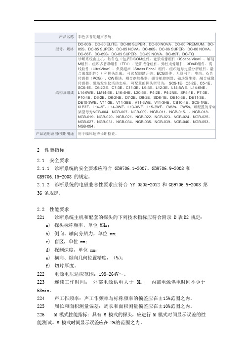
2性能指标2.1安全要求2.1.1 诊断系统的安全要求应符合 GB9706.1-2007、GB9706.9-2008 和GB9706.15-2008 的规定。
2.1.2 诊断系统的电磁兼容性要求应符合 YY 0505-2012 和 GB9706.9-2008 第36 条规定。
2.2性能要求2.2.1诊断系统主机和配套的探头的下列技术指标应符合附录 D 表D2 规定:a)探头标称频率,单位 MHz;b)侧向、轴向分辨力,单位 mm;c)盲区,单位 mm;d)探测深度,单位 mm;e)横向、纵向几何位置精度,(%);f)切片厚度。
2.2.2电源电压适应范围:198-264V~。
2.2.3连续工作时间:外部电源供电大于 8h ,内部电源供电时间不少于68min。
2.2.4声工作频率:声工作频率与标称频率的偏差应在±15%范围之内。
2.2.5周长和面积测量偏差:周长和面积测量偏差应在±10%范围之内。
2.2.6M 模式性能指标:具有 M 模式的探头,应进行 M 模式时间显示误差的性能测试。
M 模式时间显示误差应在 2%的范围之内。
2.2.7彩色血流成像模式性能要求a)在彩色血流成像模式下,各探头在其多普勒工作频率下的探测深度应不小于附录 D 表D3 彩色性能指标的要求。
b)彩色血流图像与其所在管道的灰阶图像应基本重合。
c)血流方向应能正确识别,无混叠现象。
2.2.8频谱多普勒模式性能要求a)在频谱多普勒模式下,各探头在其多普勒工作频率下的探测深度应不小于附录 D 表D3 彩色性能指标的要求。
b)彩超的血流速度读数误差应不超过附录 D 表D3 彩色性能指标的要求。
c)取样区游标位置应准确。
2.2.9自动容积测量功能(适用探头 D6-2E、DE10-3E、DE11-3E、D6-2NE、D8-2E、D7-2E、SD8-1E、DE10-3WE 支持)自动容积测量的三维重建体积计算偏差:在±20%范围内。
施耐德C65断路器

1
C
10
额定剩余动作电流 30 mA 100 mA 300 mA 100 mAs 300 mAs
可配电气附件 MX 或 MX+OF: 分励脱扣单元 MN: 欠压脱扣单元 (瞬动型) MN s : 欠压脱扣单元 (延时型) MV: 过压脱扣单元 SD: 报警接点 OF: 辅助接点 OF+SD/OF: 双重切换接点
■ 快速闭合技术 C65 系列断路器采用快速闭合设计,触头的闭合与操作者操作方式无关,这种设计将显 著降低操作时电弧对触头的影响,提高断路器的电气寿命。
当负载类型为电动机或变压器等高冲击性负载时,快速闭合技术使其效果和优势更加 明显。
■ 多种电气附件和机械辅件 C65 系列可根据用户需求选装多种电气附件,如 OF 辅助接点、SD 报警接点、MX 或 MX+OF 分励脱扣单元、MN 或 MN s 欠压脱扣单元、MV 过压脱扣单元等实现对断路 器的远程监控和控制。机械辅件如旋转手柄、挂锁辅件、间隔件等使断路器的操作和使 用更加方便和安全。
有
3P, 4P
100s,
300s
IEC61009/
GB16917
A类
230/400 ≤ 40, ≤ 63 30
Vigi C65 ELE
Vigi 附件操 剩余电流动作
1P+N, 2P, 作手柄上有 保护附件可接
无
3P, 4P 红色剩余电 25mm2 多股
流脱扣指示 软线或者
35mm2 单股
硬线
Vigi C65 ELM
OF、SD、 隧道式接线端子, OF+SD/OF、 1~32A: 25mm2, MX、MX+OF、 40~63A: 35mm2 MN、MN s 、
常用电气图形符号和文字符号
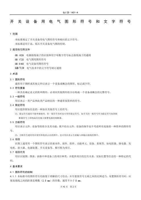
开关设备用电气图形符号和文字符号1范围本标准规定了开关设备用电气图形符号和相应的文字符号。
本标准适用于高、低压开关设备电气图的绘制。
2 规范性引用文件GB 4026 电器接线端子的识别和用字母数字符号标志接线端子的通则GB 4728 电气图用图形符号GB 5465 电气设备用图形符号GB 7159 电气技术中的文字符号制订通则3 术语3.1 图形符号通常用于图样或其他文件以表示一个设备或概念的图形、标记或字符。
3.2符号要素一种具有确定意义的简单图形,必须同其他图形组合以构成一个设备或概念的完整符号。
3.3 一般符号用以表示一类产品和此类产品特征的一种通常很简单的符号。
3.4 限定符号用以提供附加信息的一种加在其他符号上的符号。
注:限定符号通常不能单独使用,但一般符号有时也可用作限定符号,如开关的一般符号作为限定符号加到熔断器符号上即构成具有独立报警电路的熔断器。
3.5 方框符号用以表示元件、设备等的组合及其功能,既不给出元件、设备的细节也不考虑所有连接的一种简单的图形符号。
注:方框符号通常用在使用单线表示法的图中,也可用在表示全部输入和输出接线的图中。
3.6 项目在图上通常用一个图形符号表示的基本件、部件、组件、功能单元、设备、系统等。
如电阻器、继电器、发电机、放大器、电源装置、开关设备等,都可称为项目。
3.7 项目代号用以识别图、图表、表格中和设备上的项目种类,并提供项目的层次关系、实际位置等信息的一种特定的代码。
4 基本要求4.1 图形符号的绘制4.1.1本标准中的图形符号均按便于理解的尺寸绘出,并尽量使符号互相之间的比例适当。
布置图形符号时,应使连接线之间的距离是模数(2.5 mm)的倍数,通常不小于5 mm。
4.1.2本标准中的图形符号可根据需要缩小或放大,当一个图形符号用以限定另一个图形符号时,该符号常常缩小绘制。
符号缩小或放大时,各符号相互间及符号本身的比例应保持不变。
4.1.3本标准示出的图形符号方位不是强制的。
CC6-2405SF-E中文资料
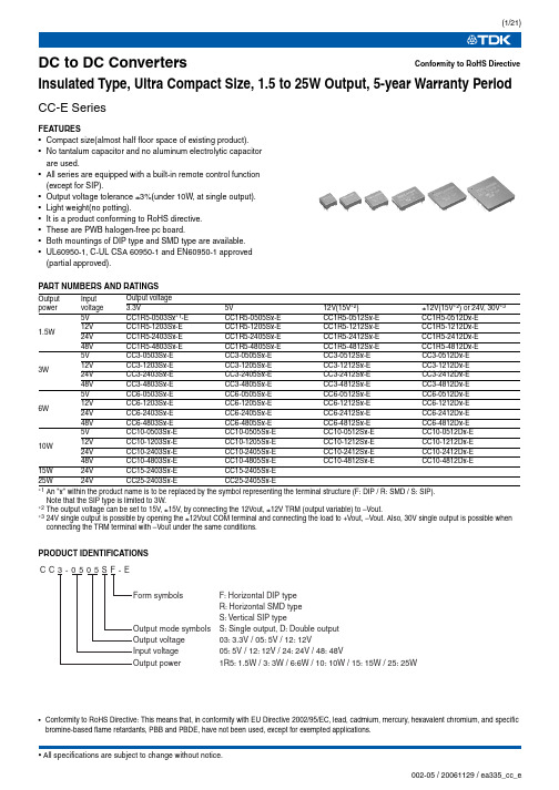
DC to DC ConvertersInsulated Type, Ultra Compact Size, 1.5 to 25W Output, 5-year Warranty PeriodCC-E SeriesFEATURES•Compact size(almost half floor space of existing product).•No tantalum capacitor and no aluminum electrolytic capacitor are used.•All series are equipped with a built-in remote control function (except for SIP).•Output voltage tolerance ±3%(under 10W, at single output).•Light weight(no potting).•It is a product conforming to RoHS directive.•These are PWB halogen-free pc board.•Both mountings of DIP type and SMD type are available.•UL60950-1, C-UL CSA 60950-1 and EN60950-1 approved (partial approved).PART NUMBERS AND RATINGS∗1An "x" within the product name is to be replaced by the symbol representing the terminal structure (F: DIP / R: SMD / S: SIP). Note that the SIP type is limited to 3W.∗2The output voltage can be set to 15V , ±15V , by connecting the 12Vout, ±12V TRM (output variable) to –Vout.∗324V single output is possible by opening the ±12Vout COM terminal and connecting the load to +Vout, –Vout. Also, 30V single output is possible when connecting the TRM terminal with –Vout under the same conditions.PRODUCT IDENTIFICATIONSConformity to RoHS Directive Output power Input voltage Output voltage3.3V 5V 12V(15V ∗2)±12V(15V ∗2) or 24V , 30V ∗31.5W5V CC1R5-0503Sx ∗1-E CC1R5-0505Sx-E CC1R5-0512Sx-E CC1R5-0512Dx-E 12V CC1R5-1203Sx-E CC1R5-1205Sx-E CC1R5-1212Sx-E CC1R5-1212Dx-E 24V CC1R5-2403Sx-E CC1R5-2405Sx-E CC1R5-2412Sx-E CC1R5-2412Dx-E 48V CC1R5-4803Sx-E CC1R5-4805Sx-E CC1R5-4812Sx-E CC1R5-4812Dx-E 3W5V CC3-0503Sx-E CC3-0505Sx-E CC3-0512Sx-E CC3-0512Dx-E 12V CC3-1203Sx-E CC3-1205Sx-E CC3-1212Sx-E CC3-1212Dx-E 24V CC3-2403Sx-E CC3-2405Sx-E CC3-2412Sx-E CC3-2412Dx-E 48V CC3-4803Sx-E CC3-4805Sx-E CC3-4812Sx-E CC3-4812Dx-E 6W5V CC6-0503Sx-E CC6-0505Sx-E CC6-0512Sx-E CC6-0512Dx-E 12V CC6-1203Sx-E CC6-1205Sx-E CC6-1212Sx-E CC6-1212Dx-E 24V CC6-2403Sx-E CC6-2405Sx-E CC6-2412Sx-E CC6-2412Dx-E 48V CC6-4803Sx-E CC6-4805Sx-E CC6-4812Sx-E CC6-4812Dx-E 10W 5V CC10-0503Sx-E CC10-0505Sx-E CC10-0512Sx-E CC10-0512Dx-E 12V CC10-1203Sx-E CC10-1205Sx-E CC10-1212Sx-E CC10-1212Dx-E 24V CC10-2403Sx-E CC10-2405Sx-E CC10-2412Sx-E CC10-2412Dx-E 48V CC10-4803Sx-E CC10-4805Sx-E CC10-4812Sx-ECC10-4812Dx-E15W 24V CC15-2403Sx-E CC15-2405Sx-E 25W24VCC25-2403Sx-E CC25-2405Sx-E•Conformity to RoHS Directive: This means that, in conformity with EU Directive 2002/95/EC, lead, cadmium, mercury, hexavalent chromium, and specific bromine-based flame retardants, PBB and PBDE, have not been used, except for exempted applications.ELECTRICAL CHARACTERISTICS∗1An "x" within the product name is to be replaced by the symbol representing the terminal structure (F: DIP / R: SMD). ∗2T otal output voltage is including input, load, and temperature regulation.∗3When the condition is 2-output, it is the balance load (balance load means the condition when the load current of +output and –output is equal).∗4Measurement bandwidth: 50MHz∗5T ypical input voltage, maximum output current.∗62-output products may be used as 24 to 30V single output with COM. terminal open.∗7TRM and –Vout are shorted.•T rim range: 3.3Vout is 3.15 to 3.6V , 5Vout is 4.75 to 6V , 12Vout is 11.4 to 15V , ±12Vout is ±11.4 to ±15V (22.8 to 30V).OUTPUT POWER - AMBIENT TEMPERATURE(DERATING)COMMON SPECIFICATIONSPart No.Input voltage (V)Output voltage ∗2(V)Output current (mA)Voltage stabilityOutput ripple noise voltage ∗4(mVp-p)typ./max.Efficiency ∗5(%) Input-output insulationInput (mV)max.Load ∗3(mV)max.T emperature (mV)1R5-0503Sx ∗1-E 4.5 to 9 3.3±3%0 to 40020408040/12071 Withstand voltage AC.500V 1minResistance DC.500V 50M Ωmin.CC1R5-0505Sx-E 4.5 to 95±3%0 to 30020408040/12077CC1R5-0512Sx-E 4.5 to 912±3%0 to 1254010020030/120804.5 to 915±3%∗70 to 1004010020030/12080CC1R5-0512Dx-E ∗6 4.5 to 9±12±5%±0 to 608060030030/120794.5 to 9±15±5%±0 to 508060030030/12079CC1R5-1203Sx-E 9 to 18 3.3±3%0 to 40020408040/12073CC1R5-1205Sx-E 9 to 185±3%0 to 30020408040/12078CC1R5-1212Sx-E 9 to 1812±3%0 to 1254010020030/120829 to 1815±3%0 to 1004010020030/12082CC1R5-1212Dx-E ∗69 to 18±12±5%±0 to 608060030030/120819 to 18±15±5%∗7±0 to 508060030030/12081CC1R5-2403Sx-E 18 to 36 3.3±3%0 to 40020408040/12072CC1R5-2405Sx-E 18 to 365±3%0 to 30020408040/12077CC1R5-2412Sx-E 18 to 3612±3%0 to 1254010020030/1208118 to 3615±3%0 to 1004010020030/12081CC1R5-2412Dx-E ∗618 to 36±12±5%±0 to 608060030030/1207918 to 36±15±5%∗7±0 to 508060030030/12079CC1R5-4803Sx-E 36 to 76 3.3±3%0 to 40020408040/12070CC1R5-4805Sx-E 36 to 765±3%0 to 30020408040/12076CC1R5-4812Sx-E 36 to 7612±3%0 to 1254010020030/1208036 to 7615±3%∗70 to 1004010020030/12080CC1R5-4812Dx-E ∗636 to 76±12±5%±0 to 608060030030/1207936 to 76±15±5%∗7±0 to 508060030030/12079Overcurrent protectionOutput current limitation system, auto recovery typeOperating temperature range–40 to +85°C[Derating is necessary whenoperating environment temperature exceed 50°C]Storage temperature range–40 to +85°CHumidity range 95(%)RH max.[Maximum wet-bulb temperature: 38°C]Vibration 10 to 55Hz, all amplitude 1.52mm, sweep time 15min[3 directions of X, Y , Z, each 2h]Amplitude980m/s 2(100G) 6ms[6 directions, each 3 times]Withstand voltage Eac Input to output, input to case, output to case: 500V , 1minInsulation resistance Input to output, input to case, output to case: 50M Ω min.[DC.500V]Safety standards UL60950-1, C-UL(CSA22.2 No.60950-1), EN60950-1 certified Weight3.2gSHAPES AND DIMENSIONS CC1R5-xxxxxF-E (DIP TYPE)RECOMMENDED PWB HOLE SIZE, LOCATION [TOP VIEW]CC1R5-xxxxxR-E (SMD TYPE)RECOMMENDED PWB HOLE SIZE, LOCATION [TOP VIEW]CONNECTIONS CC1R5-xxxxSx-ECC1R5-xxxxDx-EDimensions in mm Tolerance: ±0.5Dimensions in mm Tolerance: ±0.5TERMINAL PIN CONFIGUTATIONNo.1+Vin No.2RC No.3–Vin No.4NC No.5–Vout No.6TRM No.7+VoutTERMINAL PIN CONFIGUTATIONNo.1+Vin No.2RC No.3–Vin No.4–VoutNo.5Common out No.6TRM No.7+VoutCC3 T ype(DIP , SMD Types)ELECTRICAL CHARACTERISTICS∗1An "x" within the product name is to be replaced by the symbol representing the terminal structure (F: DIP / R: SMD). ∗2T otal output voltage is including input, load, and temperature regulation.∗3When the condition is 2-output, it is the balance load (balance load means the condition when the load current of +output and –output is equal).∗4Measurement bandwidth: 50MHz∗5T ypical input voltage, maximum output current.∗62-output products may be used as 24 to 30V single output with COM. terminal open.∗7TRM and –Vout are shorted.•T rim range: 3.3Vout is 3.15 to 3.6V , 5Vout is 4.75 to 6V , 12Vout is 11.4 to 15V , ±12Vout is ±11.4 to ±15V .OUTPUT POWER - AMBIENT TEMPERATURE(DERATING)COMMON SPECIFICATIONSPart No.Input voltage (V)Output voltage ∗2(V)Output current (mA)Voltage stabilityOutput ripple noise voltage ∗4(mVp-p)typ./max.Efficiency ∗5(%) Input-output insulationInput (mV)max.Load ∗3(mV)max.T emperature (mV)3-0503Sx ∗1-E 4.5 to 9 3.3±3%0 to 80020408040/12073Withstand voltage AC.500V 1minResistance DC.500V 50M Ωmin.CC3-0505Sx-E 4.5 to 95±3%0 to 60020408040/12077CC3-0512Sx-E 4.5 to 912±3%0 to 2504010020030/120824.5 to 915±3%∗70 to 2004010020030/12082CC3-0512Dx-E ∗6 4.5 to 9±12±5%±0 to 1258060030030/120814.5 to 9±15±5%±0 to 1008060030030/12081CC3-1203Sx-E 9 to 18 3.3±3%0 to 80020408040/12074CC3-1205Sx-E 9 to 185±3%0 to 60020408040/12079CC3-1212Sx-E 9 to 1812±3%0 to 2504010020030/120829 to 1815±3%0 to 2004010020030/12082CC3-1212Dx-E ∗69 to 18±12±5%±0 to 1258060030030/120819 to 18±15±5%∗7±0 to 1008060030030/12081CC3-2403Sx-E 18 to 36 3.3±3%0 to 80020408040/12073CC3-2405Sx-E 18 to 365±3%0 to 60020408040/12078CC3-2412Sx-E 18 to 3612±3%0 to 2504010020030/1208218 to 3615±3%0 to 2004010020030/12082CC3-2412Dx-E ∗618 to 36±12±5%±0 to 1258060030030/1208118 to 36±15±5%∗7±0 to 1008060030030/12081CC3-4803Sx-E 36 to 76 3.3±3%0 to 80020408040/12073CC3-4805Sx-E 36 to 765±3%0 to 60020408040/12079CC3-4812Sx-E 36 to 7612±3%0 to 2504010020030/1208136 to 7615±3%∗70 to 2004010020030/12081CC3-4812Dx-E ∗636 to 76±12±5%±0 to 1258060030030/1208036 to 76±15±5%∗7±0 to 1008060030030/12080Overcurrent protectionOutput current limitation system, auto recovery typeOperating temperature range–40 to +85°C[Derating is necessary whenoperating environment temperature exceed 50°C]Storage temperature range–40 to +85°CHumidity range 95(%)RH max.[Maximum wet-bulb temperature: 38°C]Amplitude 10 to 55Hz, all amplitude 1.52mm, sweep time 15min[3 directions of X, Y , Z, each 2h]Vibration980m/s 2(100G) 6ms[6 directions, each 3 times]Withstand voltage Eac Input to output, input to case, output to case: 500V , 1minInsulation resistance Input to output, input to case, output to case: 50M Ω min.[DC.500V]Safety standards UL60950-1, C-UL(CSA22.2 No.60950-1), EN60950-1 certified Weight4.5gCC3 T ype(SI P T ype)ELECTRICAL CHARACTERISTICS∗1T otal output voltage is including input, load, and temperature regulation.∗2When the condition is 2-output, it is the balance load (balance load means the condition when the load current of +output and –output is equal).∗3Measurement bandwidth: 50MHz∗4T ypical input voltage, maximum output current.∗52-output products may be used as 24 to 30V single output with COM. terminal open.∗6TRM and –Vout are shorted.•T rim range: 3.3Vout is 3.15 to 3.67V , 5Vout is 4.75 to 6V , 12Vout is 11.4 to 15V , ±12Vout is ±11.4 to ±15V .OUTPUT POWER - AMBIENT TEMPERATURE(DERATING)COMMON SPECIFICATIONSPart No.Input voltage (V)Output voltage ∗1(V)Output current (mA)Voltage stabilityOutput ripple noise voltage ∗3(mVp-p)typ./max.Efficiency ∗4(%) Input-output insulationInput (mV)max.Load ∗2(mV)max.T emperature (mV)3-0503SS-E 4.5 to 9 3.3±3%0 to 80020408040/12073Withstand voltage AC.500V 1minResistance DC.500V 50M Ωmin.CC3-0505SS-E 4.5 to 95±3%0 to 60020408040/12077CC3-0512SS-E 4.5 to 912±3%0 to 2504010020030/120824.5 to 915±3%∗60 to 2004010020030/12082CC3-0512DS-E ∗5 4.5 to 9±12±5%±0 to 1258060030030/120814.5 to 9±15±5%±0 to 1008060030030/12081CC3-1203SS-E 9 to 18 3.3±3%0 to 80020408040/12073CC3-1205SS-E 9 to 185±3%0 to 60020408040/12079CC3-1212SS-E 9 to 1812±3%0 to 2504010020030/120829 to 1815±3%0 to 2004010020030/12082CC3-1212DS-E ∗59 to 18±12±5%±0 to 1258060030030/120829 to 18±15±5%∗6±0 to 1008060030030/12082CC3-2403SS-E 18 to 36 3.3±3%0 to 80020408040/12073CC3-2405SS-E 18 to 365±3%0 to 60020408040/12078CC3-2412SS-E 18 to 3612±3%0 to 2504010020030/1208218 to 3615±3%0 to 2004010020030/12082CC3-2412DS-E ∗518 to 36±12±5%±0 to 1258060030030/1208118 to 36±15±5%∗6±0 to 1008060030030/12081CC3-4803SS-E 36 to 76 3.3±3%0 to 80020408040/12073CC3-4805SS-E 36 to 765±3%0 to 60020408040/12079CC3-4812SS-E 36 to 7612±3%0 to 2504010020030/1208236 to 7615±3%∗60 to 2004010020030/12082CC3-4812DS-E ∗536 to 76±12±5%±0 to 1258060030030/1208236 to 76±15±5%∗6±0 to 1008060030030/12082Overcurrent protectionOutput current limitation system, auto recovery typeOperating temperature range–40 to +85°C[Derating is necessary whenoperating environment temperature exceed 50°C]Storage temperature range–40 to +85°CHumidity range 95(%)RH max.[Maximum wet-bulb temperature: 38°C]Amplitude 10 to 55Hz, all amplitude 1.52mm, sweep time 15min[3 directions of X, Y , Z, each 2h]Vibration980m/s 2(100G) 6ms[6 directions, each 3 times]Withstand voltage Eac Input to output, input to case, output to case: 500V , 1minInsulation resistance Input to output, input to case, output to case: 50M Ω min.[DC.500V]Safety standards UL60950-1, C-UL(CSA22.2 No.60950-1), EN60950-1 certified is applying partially.Weight7.0gCC3 T ype(DIP , SMD Types)SHAPES AND DIMENSIONS CC3-xxxxxF-E (DIP TYPE)RECOMMENDED PWB HOLE SIZE, LOCATIONCC3-xxxxxR-E (SMD TYPE)RECOMMENDED PWB HOLE SIZE, LOCATION [TOP VIEW]CONNECTIONS CC3-xxxxSx-ECC3-xxxxDx-EDimensions in mm Tolerance: ±0.5TERMINAL PIN CONFIGUTATIONNo.1+Vin No.2RC No.3–Vin No.4NC No.5–Vout No.6TRM No.7+VoutTERMINAL PIN CONFIGUTATIONNo.1+Vin No.2RC No.3–Vin No.4–VoutNo.5Common out No.6TRM No.7+VoutCC3 T ype(SI P T ype)SHAPES AND DIMENSIONS CC3-xxxxxS-E (SIP TYPE)CONNECTIONS CC3-xxxxSS-ECC3-xxxxDS-EThe output voltage can be set to 15V , ±15V , by connecting the output variable terminal TRM of the 12Vout, ±12V output model to –Vout.24V single output is possible by opening the ±12Vout COM terminal andconnecting the load to +Vout, –Vout. Also, 30V single output is possible when connecting the TRM terminal with –Vout under the same conditions.TERMINAL PIN CONFIGUTATIONNo.1+Vout No.2NC No.3NC No.4–Vout No.5TRM No.6NC No.7–Vin No.8–Vin No.9+Vin No.10+VinTERMINAL PIN CONFIGUTATIONNo.1+Vout No.2COM No.3COM No.4–Vout No.5TRM No.6NC No.7–Vin No.8–Vin No.9+Vin No.10+VinELECTRICAL CHARACTERISTICS∗1An "x" within the product name is to be replaced by the symbol representing the terminal structure (F: DIP / R: SMD). ∗2T otal output voltage is including input, load, and temperature regulation.∗3When the condition is 2-output, it is the balance load (balance load means the condition when the load current of +output and –output is equal).∗4Measurement bandwidth: 50MHz∗5T ypical input voltage, maximum output current∗62-output products may be used as 24 to 30V single output with COM. terminal open.∗7TRM and –Vout are shorted.•T rim range: 3.3Vout is 3.15 to 3.6V , 5Vout is 4.75 to 6V , 12Vout is 11.4 to 15V , ±12Vout is ±11.4 to ±15V .OUTPUT POWER - AMBIENT TEMPERATURE(DERATING)COMMON SPECIFICATIONSPart No.Input voltage (V)Output voltage ∗2(V)Output current (mA)Voltage stabilityOutput ripple noise voltage ∗4(mVp-p)typ./max.Efficiency ∗5(%) Input-output insulationInput (mV)max.Load ∗3(mV)max.T emperature (mV)6-0503Sx ∗1-E 4.5 to 9 3.3±3%0 to 120020408040/12076Withstand voltage AC.500V 1minResistance DC.500V 50M Ωmin.CC6-0505Sx-E 4.5 to 95±3%0 to 100020408040/12079CC6-0512Sx-E 4.5 to 912±3%0 to 5004010020030/120824.5 to 915±3%∗70 to 4004010020030/12082CC6-0512Dx-E ∗6 4.5 to 9±12±5%±0 to 2508060030030/120824.5 to 9±15±5%±0 to 2008060030030/12082CC6-1203Sx-E 9 to 18 3.3±3%0 to 120020408040/12078CC6-1205Sx-E 9 to 185±3%0 to 120020408040/12082CC6-1212Sx-E 9 to 1812±3%0 to 5004010020030/120859 to 1815±3%0 to 4004010020030/12085CC6-1212Dx-E ∗69 to 18±12±5%±0 to 2508060030030/120859 to 18±15±5%∗7±0 to 2008060030030/12085CC6-2403Sx-E 18 to 36 3.3±3%0 to 120020408040/12077CC6-2405Sx-E 18 to 365±3%0 to 120020408040/12081CC6-2412Sx-E 18 to 3612±3%0 to 5004010020030/1208718 to 3615±3%0 to 4004010020030/12087CC6-2412Dx-E ∗618 to 36±12±5%±0 to 2508060030030/1208618 to 36±15±5%∗7±0 to 2008060030030/12086CC6-4803Sx-E 36 to 76 3.3±3%0 to 120020408040/12077CC6-4805Sx-E 36 to 765±3%0 to 120020408040/12081CC6-4812Sx-E 36 to 7612±3%0 to 5004010020030/1208636 to 7615±3%∗70 to 4004010020030/12086CC6-4812Dx-E ∗636 to 76±12±5%±0 to 2508060030030/1208636 to 76±15±5%∗7±0 to 2008060030030/12086Overcurrent protectionOutput current limitation system, auto recovery typeOperating temperature range–40 to +85°C[Derating is necessary whenoperating environment temperature exceed 50°C]Storage temperature range–40 to +85°CHumidity range 95(%)RH max.[Maximum wet-bulb temperature: 38°C]Amplitude 10 to 55Hz, all amplitude 1.52mm, sweep time 15min[3 directions of X, Y , Z, each 2h]Vibration980m/s 2(100G) 6ms[6 directions, each 3 times]Withstand voltage Eac Input to output, input to case, output to case: 500V , 1minInsulation resistance Input to output, input to case, output to case: 50M Ω min.[DC.500V]Safety standards UL60950-1, C-UL(CSA22.2 No.60950-1), EN60950-1 certified Weight5.8gSHAPES AND DIMENSIONS CC6-xxxxxF-E (DIP TYPE)RECOMMENDED PWB HOLE SIZE, LOCATIONCC6-xxxxxR-E (SMD TYPE)RECOMMENDED PWB HOLE SIZE, LOCATION [TOP VIEW]CONNECTIONS CC6-xxxxSx-ECC6-xxxxDx-EDimensions in mm Tolerance: ±0.5TERMINAL PIN CONFIGUTATIONNo.1+Vin No.2RC No.3–Vin No.4NC No.5–Vout No.6TRM No.7+VoutTERMINAL PIN CONFIGUTATIONNo.1+Vin No.2RC No.3–Vin No.4–VoutNo.5Common out No.6TRM No.7+VoutELECTRICAL CHARACTERISTICS∗1An "x" within the product name is to be replaced by the symbol representing the terminal structure (F: DIP / R: SMD). ∗2T otal output voltage is including input, load, and temperature regulation.∗3When the condition is 2-output, it is the balance load (balance load means the condition when the load current of +output and –output is equal).∗4Measurement bandwidth: 50MHz∗5T ypical input voltage, maximum output current∗62-output products may be used as 24 to 30V single output with COM. terminal open.∗7TRM and –Vout are shorted.•T rim range: 3.3Vout is 3.15 to 3.6V , 5Vout is 4.75 to 6V , 12Vout is 11.4 to 15V , ±12Vout is ±11.4 to ±15V .OUTPUT POWER - AMBIENT TEMPERATURE(DERATING)COMMON SPECIFICATIONSPart No.Input voltage (V)Output voltage ∗2(V)Output current (mA)Voltage stabilityOutput ripple noise voltage ∗4(mVp-p)typ./max.Efficiency ∗5(%) Input-output insulationInput (mV)max.Load ∗3(mV)max.T emperature (mV)10-0503Sx ∗1-E 4.5 to 9 3.3±3%0 to 250020408040/12084Withstand voltage AC.500V 1minResistance DC.500V 50M Ωmin.CC10-0505Sx-E 4.5 to 95±3%0 to 200020408040/12084CC10-0512Sx-E 4.5 to 912±3%0 to 8004010020030/120844.5 to 915±3%∗70 to 6404010020030/12084CC10-0512Dx-E ∗6 4.5 to 9±12±5%±0 to 4008060030030/120834.5 to 9±15±5%±0 to 3208060030030/12083CC10-1203Sx-E 9 to 18 3.3±3%0 to 250020408040/12084CC10-1205Sx-E 9 to 185±3%0 to 200020408040/12086CC10-1212Sx-E 9 to 1812±3%0 to 10004010020030/120889 to 1815±3%0 to 8004010020030/12088CC10-1212Dx-E ∗69 to 18±12±5%±0 to 4508060030030/120869 to 18±15±5%∗7±0 to 3608060030030/12086CC10-2403Sx-E 18 to 36 3.3±3%0 to 250020408040/12084CC10-2405Sx-E 18 to 365±3%0 to 200020408040/12086CC10-2412Sx-E 18 to 3612±3%0 to 10004010020030/1208718 to 3615±3%0 to 8004010020030/12087CC10-2412Dx-E ∗618 to 36±12±5%±0 to 4508060030030/1208618 to 36±15±5%∗7±0 to 3608060030030/12086CC10-4803Sx-E 36 to 76 3.3±3%0 to 250020408040/12084CC10-4805Sx-E 36 to 765±3%0 to 200020408040/12086CC10-4812Sx-E 36 to 7612±3%0 to 10004010020030/1208836 to 7615±3%∗70 to 8004010020030/12088CC10-4812Dx-E ∗636 to 76±12±5%±0 to 4508060030030/1208636 to 76±15±5%∗7±0 to 3608060030030/12086Overcurrent protectionOutput current limitation system, auto recovery typeOperating temperature range–40 to +85°C[Derating is necessary whenoperating environment temperature exceed 50°C]Storage temperature range–40 to +85°CHumidity range 95(%)RH max.[Maximum wet-bulb temperature: 38°C]Amplitude 10 to 55Hz, all amplitude 1.52mm, sweep time 15min[3 directions of X, Y , Z, each 2h]Vibration980m/s 2(100G) 6ms[6 directions, each 3 times]Withstand voltage Eac Input to output, input to case, output to case: 500V , 1minInsulation resistance Input to output, input to case, output to case: 50M Ω min.[DC.500V]Safety standards UL60950-1, C-UL(CSA22.2 No.60950-1), EN60950-1 certified Weight10.0gSHAPES AND DIMENSIONS CC10-xxxxxF-E (DIP TYPE)RECOMMENDED PWB HOLE SIZE, LOCATION [TOP VIEW]CC10-xxxxxR-E (SMD TYPE)RECOMMENDED PWB HOLE SIZE, LOCATION [TOP VIEW]CONNECTIONS CC10-xxxxSx-ECC10-xxxxDx-EDimensions in mm Tolerance: ±0.5Dimensions in mm Tolerance: ±0.5TERMINAL PIN CONFIGUTATIONNo.1+Vin No.2RC No.3–Vin No.4NC No.5–Vout No.6TRM No.7+VoutTERMINAL PIN CONFIGUTATIONNo.1+Vin No.2RC No.3–Vin No.4–VoutNo.5Common out No.6TRM No.7+VoutELECTRICAL CHARACTERISTICS∗1An "x" within the product name is to be replaced by the symbol representing the terminal structure (F: DIP / R: SMD). ∗2T otal output voltage is including input, load, and temperature regulation.∗3Measurement bandwidth: 50MHz∗4T ypical input voltage, maximum output currentOUTPUT POWER - AMBIENT TEMPERATURE(DERATING)COMMON SPECIFICATIONSPart No.Input voltage (V)Output voltage ∗2(V)Output current (mA)Voltage stabilityOutput ripple noisevoltage ∗3(mVp-p)typ./max.Efficiency ∗4(%) Input-output insulation Input (mV)max.Load (mV)max.T emperature (mV)max.CC15-2403Sx ∗1-E 18 to 36 3.3/–3 to +5%0 to 4500401208040/12089Withstand voltage AC.500V 1minResistance DC.500V 50M Ωmin.CC15-2405Sx-E18 to 36 5.0/–3 to +5%0 to 3000502008040/12089Overcurrent protectionOutput current limitation system, Output voltage shut-down typeOperating temperature range–40 to +85°C[Derating is necessary whenoperating environment temperature exceed 50°C]Storage temperature range–40 to +85°CHumidity range 95(%)RH max.[Maximum wet-bulb temperature: 38°C]Amplitude 10 to 55Hz, all amplitude 1.52mm, sweep time 15min[3 directions of X, Y , Z, each 2h]Vibration980m/s (100G) 6ms[6 directions, each 3 times]Withstand voltage Eac Input to output, input to case, output to case: 500V , 1minInsulation resistance Input to output, input to case, output to case: 50M Ω min[DC.500V]Safety standards UL60950-1, C-UL(CSA22.2 No.60950-1), EN60950-1 certified Weight12.5gSHAPES AND DIMENSIONS CC15-xxxxSF-E (DIP TYPE)RECOMMENDED PWB HOLE SIZE, LOCATION [TOP VIEW]CC15-xxxxSR-E (SMD TYPE)RECOMMENDED PWB HOLE SIZE, LOCATION [TOP VIEW]CONNECTIONDimensions in mm Tolerance: ±0.5Dimensions in mm Tolerance: ±0.5TERMINAL PIN CONFIGUTATIONNo.1NC No.10NC No.2NC No.11NC No.3RC No.12+Vout No.4NC No.13+Vout No.5NC No.14+Vout No.6+Vin No.15–Vout No.7+Vin No.16–Vout No.8–Vin No.17NCNo.9–VinELECTRICAL CHARACTERISTICS∗1An "x" within the product name is to be replaced by the symbol representing the terminal structure (F: DIP / R: SMD). ∗2T otal output voltage is including input, load, and temperature regulation.∗3Measurement bandwidth: 50MHz∗4T ypical input voltage, maximum output currentOUTPUT POWER - AMBIENT TEMPERATURE(DERATING)COMMON SPECIFICATIONSPart No.Input voltage (V)Output voltage ∗2(V)Output current (mA)Voltage stabilityOutput ripple noisevoltage ∗3(mVp-p)typ./max.Efficiency ∗4(%) Input-output insulation Input (mV)max.Load (mV)max.T emperature (mV)max.CC25-2403Sx ∗1-E 18 to 36 3.3/–3 to +5%0 to 7500401208040/12090Withstand voltage AC.500V 1minResistance DC.500V 50M Ωmin.CC25-2405Sx-E18 to 36 5.0/–3 to +5%0 to 5000502008040/12090Overcurrent protectionOutput current limitation system, Output voltage shut-down typeOperating temperature range–40 to +85°C[Derating is necessary whenoperating environment temperature exceed 50°C]Storage temperature range–40 to +85°CHumidity range 95(%)RH max.[Maximum wet-bulb temperature: 38°C]Amplitude 10 to 55Hz, all amplitude 1.52mm, sweep time 15min[3 directions of X, Y , Z, each 2h]Vibration500m/s (51G) 6ms[6 directions, each 3 times]Withstand voltage Eac Input to output, input to case, output to case: 500V , 1minInsulation resistance Input to output, input to case, output to case: 50M Ω min.[DC.500V]Safety standards UL60950-1, C-UL(CSA22.2 No.60950-1), EN60950-1 certified Weight20.0gSHAPES AND DIMENSIONS CC25-xxxxSF-E (DIP TYPE)RECOMMENDED PWB HOLE SIZE, LOCATION [TOP VIEW]CC25-xxxxSR-E (SMD TYPE)RECOMMENDED PWB HOLE SIZE, LOCATION [TOP VIEW]CONNECTIONDimensions in mm Tolerance: ±0.5Dimensions in mm Tolerance: ±0.5TERMINAL PIN CONFIGUTATIONNo.1NC No.10+Vin No.19–Vout No.2NC No.11+Vin No.20–Vout No.3NC No.12+Vin No.21–Vout No.4RC No.13NC No.22–Vout No.5NC No.14NC No.23–Vout No.6NC No.15+Vout No.24–Vout No.7–Vin No.16+Vout No.25NCNo.8–Vin No.17+Vout No.9–Vin No.18+VoutREMOTE CONTROL TERMINAL(RC)(DIP/SMD MODELS)1.5 to 10W TypesIt is recommended to use an open collector as the control method for the remote control terminal. If other methods are necessary, please contact TDK first.In addition, please use a transistor with V CE: Over Vin and Ic: Over 1mA.When the RC terminal is open, the output is OFF, and when the RC terminal and –Vin are shorted (0 to 0.4V) the output is ON.If not using this function (always ON), short-circuit the RC terminal and the –Vin terminal.15 and 25W TypesWhen the RC terminal is open, the output is ON, and when the RC terminal is HIGH (connected to +Vin) the output is OFF.If not using this function (always ON), short-circuit the RC terminal and the –Vin terminal.OUTPUT VARIABLE TERMINAL(TRM)(1.5 to 10W Types)The output voltage can be set to the value shown in the following table by connecting the TRM terminal with the –Vout terminal. Please open the TRM terminal when not using this function. Please take note that it is necessary to derate the output current to match the maximum power when the output voltage is set higher by this function.DIP/SMD Models∗ T o be replaced by 1R5(1.5W), 3(3W), 6(6W) and 10(10W).Fig.1Fig.2SIP ModelFig.3Fig.4Part No.Open Connected with –Vout Fig. CCx∗–xx03Sx 3.3V 3.6V1 CCx–xx05Sx 5.0V 6.0V1 CCx–xx12Sx12V15V1 CCx–xx12Dx±12V±15V2Part No.Open Connected with –Vout Fig. CC3–xx03SS–E 3.3V 3.67V3 CC3–xx05SS–E5V6V3 CC3–xx12SS–E12V15V3 CC3–xx12DS–E±12V±15V4With the ±12V , 24V single output is possible by opening the COM terminal and TRM terminal. Also, 30V single output is possible when opening the COM terminal and connecting the TRM terminal with the –Vout terminal.DIP/SMD Models∗ T o be replaced by 1R5(1.5W), 3(3W), 6(6W) and 10(10W).Fig.5Fig.6SIP ModelFig.7Fig.8OUTPUT VARIABILITY FUNCTION (ADDING EXTERNAL RESISTANCE)(1.5 to 10W Types)The output voltage can be adjusted within the range shown in the following table by connecting resistance (Ra, Rb) between the TRM terminal and the –Vout terminal, or between the TRM termi-nal and the +Vout terminal.Please take note that it is necessary to derate the output current to match the maximum power when the output voltage is setted higher.DIP/SMD Models∗ T o be replaced by 1R5(1.5W), 3(3W), 6(6W) and 10(10W).Calculate the output voltage Vout(V) from the connected resistance Ra, Rb(k Ω)Set the output voltage higher by adding resistance Ra between the TRM terminal/–Vout terminal.∗1 Vout=3.3+9.59/(32+Ra)∗2 Vout=5.01+17.64/(17.8+Ra)∗3 Vout=12.01+50.53/(16.9+Ra)∗4 Vout=12.02+53.55/(18+Ra)Set the output voltage lower by adding resistance Rb between the TRM terminal/+Vout terminal.∗5∗6∗7∗8Calculate the connected resistance Ra and Rb(k Ω) from the set output voltage Vout(V).Set the output voltage higher by adding resistance Ra between the TRM terminal/–Vout terminal.∗1 Ra=9.59/(Vout–3.3)–32∗2 Ra=17.64/(Vout–5.01)–17.8∗3 Ra=50.53/(Vout–12.01)–16.9∗4 Ra=53.55/(Vout–12.02)–18Set the output voltage lower by adding resistance Rb between the TRM terminal/+Vout terminal.∗5 Rb=15.53/(3.3–Vout)–39.6∗6 Rb=52.55/(5.01–Vout)–31.8∗7 Rb=431.1/(12.01–Vout)–57∗8 Rb=968.5/(12.02–Vout)–103Fig.9Fig.10Fig.11Fig.12Part No.COM terminal TRM terminal Single output x ∗–xx12Dx–EOpen Open24V 5OpenConnected with –Vout30V6Part terminal TRM terminal Single output 3–xx12DS–EOpen Open24V 7OpenConnected with –Vout30V8Part No.Connecting –Vout with RaFig.Connecting +Vout with Rbx –xx03Sx–E 3.3 to 3.6V 9 3.15 to 3.3V 10CCx–xx05Sx–E 5 to 6V 9 4.75 to 5V 10CCx–xx12Sx–E 12 to 15V ∗3911.4 to 12V ∗710CCx–xx12Dx–E±12 to ±15V 11±11.4 to ±12V 12。
ABB高压铸铁电动机产品手册
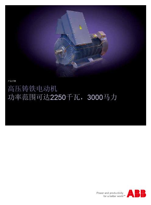
产品手册
高压铸铁电动机
功率范围可达2250千瓦,3000马力
肋片的设计应确保有一个较大的散热区域。
肋片的形状还
线圈质量决定电动机的可靠性。
HXR系列电动机定子绕组The quality of the winding is a key factor in overall
电动机转子笼用铜、铜合金或导电性非常好的铝合金材料The rotor cage is constructed using deep bars of either
3 All auxiliaries are wired to a separate connection box. The connection diagram is attached inside the cover. 12
3
ABB works with its customers around the world to offer
我们与全球用户一起合作提供灵活的解决方案来满足用户
联系我们
9A K K 104629 C N 08-2010
© 2010 ABB 公司版权所有,保留所有权利。
未经ABB 公司允许,不得以任何方式对本出版物的内容进行复制、抄录、传播或出版。
ABB 高压电机有限公司
中国上海闵行区天星路380号电话:+86 21 6113 7688传真:+86 21 6113 7788邮编:200245
/motors&generators。
粉末冶金材料标准表
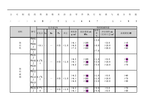
公司制造的铁基粉末冶金零件执行标准与成分性能<一>G B/T14667.1-9 3-70HT 480 550<0.5 420 25 58 7.0 F-0008-20-25-30-35140 200 170 <0.5 190 35HRBN/A5.8170 240 210 <0.5 210 50 6.2210 290 240 <1.0 210 60 6.6240 390 260 1.0 25070 7.0 F-0008-50HT-65HT-75HT-85HT380 450<0.5S 480 22HRC 60HRC 6.3450520 <0.5 55028 60 6.6520 590 <0.5 620 32 60 6.9590 660 <0.5 690 35 60 7.1烧结铁和烧结碳钢的化学成分(%).材料牌号Fe CF-0000 97.7-100 0.0-0.3F-0005 97.4-99.7 0.3-0.6F-0008 97.1-99.4 0.6-0.9注:用差减法求出的其它元素(包括为了特殊目的而添加的其它元素)总量的最大值为2.0%。
▲注:用差减法求出的其它元素(包括为了特殊目的而添加的其它元素)总量的最大烧结铁-铜合金和烧结铜钢的化学成分(%).材料牌号Fe Cu CFC-0200 83.8-98.5 1.5-3.9 0.0-0.3FC-0205 93.5-98.2 1.5-3.9 0.3-0.6FC-020893.2-97.9 1.5-3.9 0.6-0.9FC-0505 91.4-95.7 4.0-6.0 0.3-0.6FC-0508 91.1-95.4 4.0-6.0 0.6-0.9FC-0808 88.1-92.4 7.0-9.0 0.6-0.9FC-1000 87.2-90.5 9.5-10.5 0.0-0.3烧结铁-镍合金和烧结镍钢的化学成分(%).材料牌号Fe Ni Cu CFN-0200 92.2-99.0 1.0-3.0 0.0-2.5 0.0-0.3FN-0205 91.9-98.7 1.0-3.0 0.0-2.5 0.3-0.6FN-0208 91.6-98.4 1.0-3.0 0.0-2.5 0.6-0.9FN-0405 89.9-96.7 3.0-5.5 0.2-2.0 0.3-0.6FN-0408 89.6-96.4 3.0-5.5 0.0-2.0 0.6-0.9注:用差减法求出的其它元素(包括为了特殊目的而添加的其它元素)总量的最大值为2.0%⊙铁-铜合金和铜钢粉末冶金材料性能(MPIF-35)材料编号最小强度(A)(E) 拉伸性能横向断裂压缩屈服强度(0.1%)硬度密度屈服极限极限强度屈服强度(0.2%)伸长率(25.4mm)宏观(表现)微观(换算的)MPa MPa MPa % MPa MPa 络氏g/cm3 FC-0200-15-18-21100 170 140 1.0 310 12011HRB N/A6.0120 190 160 1.5 350140 18 6.3⊙<三>"DINV30910"及"ISO5755"(成分与性能略)<规格二-不锈钢>TypeChemicalComposition(%)PhysicalMechanicalPropertiesFeCrNi Cu TinSiMnMoCSOtherDensity(g/cm 3) UltimateTensileStrength (kg/mm 2) Elong-ation(%) Hard-nessSUS303LSC bal 18.212.5 2.0 1.0 0.8 0.13 – <0.080.20 <1.0 >6.320Min.Min.2.0RB40SUS316LSC bal 17.0 13.52.0 1.00.75 0.12 2.2 <0.08 0.01 <1.0 >6.3 25Min. Min.5.0 RB38SUS410L bal 12.7 – – – 0.80.18 – <0.08 0.01<1.0 >6.3 20Min. Min.2.0 RB80。
一次性医用耗材物品六位分类编码

正畸材料
GS0035 GS0036 GS0037 GS0038 GS0039 GT GT0001 GU GV GV0001 J JA JA01 JA02 GA0201 GA0202 JA03 JA0301 JA0302 JA0303 JA0304 JA0305 JA04 JA0401 JA0402 JA0403 JA0404 JA05 JA0501 JA0502 JA0503 JA0504 JA06 JA0601 JA0602 JA0603 JA0604 JA0605 JB JB01 JB0101 JB0102 JB02 JB0201 JB0202 JB0203 JC
粘接剂
金属材料
义齿材料
GR0022 GR0023 GR0024 GR0025 GR0026 GR0027 GR0028 GR0029 GR0030 GR0031 GR0032 GR0033 GR0034 GR0035 GR0036 GR0037 GR0038 GR0039 GR0040 GR0041 GR0042 GR0043 GR0044 GR0045 GR0046 GR0047 GR0048 GR0049 GR0050 GR0051 GR0052 GR0053 GR0054 GR0055 GR0056 GR0057 GR0058 GR0059 GR0060 GR0061 GR0062 GR0063 GR0064 GR0065 GR0066 GR0067 GR0068
《全国医疗服务价格项目规范》(2010版)一次性医用耗材物品六位分类编码
分类编码名称(6位) 编码 A AA AA01 AA0101 AA0102 AA0103 AA0104 AA0105 AA0106 AA0107 AA0108 AA0109 AA0110 AA0111 AA0112 AA0113 AA0114 AA0115 AA02 AA0201 AA0202 AA0203 AA0204 AA0205 AA0206 AA0207 AA0208 AA03 AA0301 AA0302 AA04 AA0401 AA05 AA0501 AA06 AA0601 AA0602 AA0603 AA0604 AA0605 AA0606 AA0607 一级分类 医用工具类 二级分类 手术器械 刀 三级分类
C.A 6550 或 C.A 6555绝缘电阻测试仪用户手册说明书
10 kV/15kV高壓絕緣電阻測試儀14感謝您購買了絕緣電阻測試儀C.A 6550或C.A 6555。
為了從儀器得到最好效果:n仔細閱讀本操作指南,n遵守使用預防措施。
警告,有危險的可能!操作人員無論在任何這個符號出現的時候必須參照本指南。
雙重絕緣保護設備注意!電擊的危險。
USB插口。
接地。
CE標記表示遵照歐洲法規,特別是LVD和EMC。
Chauvin Arnoux公司採用生態設計途徑以設計本設備。
完整生命週期的分析允許我們控制並優化環保方面產品的效果。
特別在回收和再利用方面本設備超出規定所要求。
在垃圾桶上劃線表示在歐盟,產品必須經歷。
本產品不能作為家居廢物處理。
測量種類的定義:n測量種類IV對應低壓設備源的測量。
舉例:電力饋線,電腦和保護設備。
n測量種類III對應建築設備的測量。
舉例:分布面板,電路斷路器,機器或固定工業設備。
n測量種類II對應直接連接到低壓設備的電路的測量。
舉例:供電電源到家用電器和便攜工具。
使用預防措施此儀器和附件符合安全標準IEC 61010-1, IEC 61010-031, and IEC 61010-2-030的低於2000m海拔高度,室內污染程度不超過2級的IV類1000V電壓。
沒有遵守安全指南可能導致電擊,火災,爆炸和儀器設備的損壞。
n操作人員和/或負責機構必須仔細閱讀並清晰理解使用中的預防措施。
使用儀器需要有扎實的知識和電擊的敏銳感官。
n如果你沒有按照說明使用儀器,儀器提供的保護可能被損壞,從而危及到你。
n不要使用那些超出所提到的電壓和類別的電網上的儀器。
n如果儀器看起來損壞,不完整或沒有關好就不要使用。
n每次使用前,檢查導線,外殼,和附件上的絕緣狀況,任何部件絕緣惡化(即使是部分)也必須留待維修或報廢。
n只使用提供的導線和附件。
使用更低壓或類別的導線(或附件)會減少組合儀器+導線(或附件)的電壓或類別。
n系統地使用個人保護設備。
n將雙手遠離已啟動終端。
n操作導線,測試探頭,鱷魚夾時,保持手指在物理防護裝置後面。
金升阳 CF0505XT-1WR3 1W DC DC模块电源 数据手册说明书
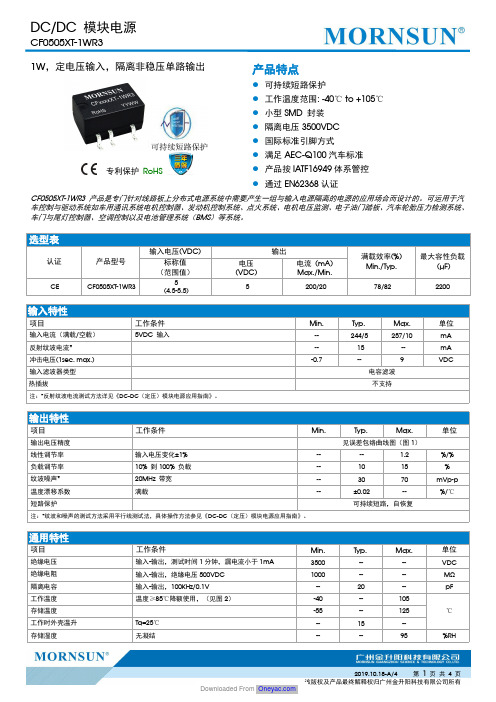
1W ,定电压输入,隔离非稳压单路输出专利保护RoHS产品特点●可持续短路保护●工作温度范围:-40℃to +105℃●小型SMD 封装●隔离电压3500VDC ●国际标准引脚方式●满足AEC-Q100汽车标准●产品按IATF16949体系管控●通过EN62368认证CF0505XT-1WR3产品是专门针对线路板上分布式电源系统中需要产生一组与输入电源隔离的电源的应用场合而设计的。
可运用于汽车控制与驱动系统如车用通讯系统电机控制器、发动机控制系统、点火系统、电机电压监测、电子油门踏板、汽车轮胎压力检测系统、车门与尾灯控制器、空调控制以及电池管理系统(BMS )等系统。
选型表认证产品型号输入电压(VDC)输出满载效率(%)Min./Typ.最大容性负载(µF)标称值(范围值)电压(VDC)电流(mA)Max./Min.CECF0505XT-1WR35(4.5-5.5)5200/2078/822200输入特性项目工作条件Min.Typ.Max.单位输入电流(满载/空载)5VDC 输入--244/5257/10mA 反射纹波电流*--15--mA 冲击电压(1sec.max.)-0.7--9VDC输入滤波器类型电容滤波热插拔不支持注:*反射纹波电流测试方法详见《DC-DC (定压)模块电源应用指南》。
输出特性项目工作条件Min.Typ.Max.单位输出电压精度见误差包络曲线图(图1)线性调节率输入电压变化±1%---- 1.2%/%负载调节率10%到100%负载--1015%纹波噪声*20MHz 带宽--3070mVp-p 温度漂移系数满载--±0.02--%/℃短路保护可持续短路,自恢复注:*纹波和噪声的测试方法采用平行线测试法,具体操作方法参见《DC-DC (定压)模块电源应用指南》。
通用特性项目工作条件Min.Typ.Max.单位绝缘电压输入-输出,测试时间1分钟,漏电流小于1mA 3500----VDC 绝缘电阻输入-输出,绝缘电压500VDC 1000----M Ω隔离电容输入-输出,100KHz/0.1V --20--pF工作温度温度≥85℃降额使用,(见图2)-40--105℃存储温度-55--125工作时外壳温升Ta=25℃--15--存储湿度无凝结----95%RH回流焊温度*峰值温度Tc ≤245℃,217℃以上时间最大为60s开关频率满载,输入标称电压--270--KHz平均无故障时间(MTBF )MIL-HDBK-217F@25℃3500----K hours 振动频率10-1000Hz ,振幅1mm ,加速度10g ,X,Y,Z 各4个循环潮敏等级(MSL)IPC/JEDEC J-STD-020D.1等级1注:*实际应用请参考IPC/JEDEC J-STD-020D.1标准。
cc1150中文
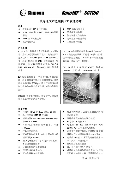
第 - 2 - 页 共 46 页
目录 1 缩写词 ......................................................................................................................................... 2 2 绝对最大等级 ............................................................................................................................. 5 3 工作条件 ..................................................................................................................................... 5 4 电气规范 ..................................................................................................................................... 5 5 常规特性 ..................................................................................................................................... 6 6 RF 传输环节 .............................................................
便携式彩色多普勒超声诊断系统产品技术要求深圳开立
2性能指标2.1性能要求2.1.1主要性能指标仪器主机和配套的各种探头的主要技术性能应符合附录 C 表 C1 的规定。
2.1.2连续工作时间:>8h;内部电源供电时,连续工作时间>1.5h。
2.1.3电源电压适应范围:90-264V~。
2.1.4声工作频率:声工作频率与标称中心频率的偏差应在±15%范围之内。
2.1.5切片厚度:切片厚度的指标应不大于附录 C 表C1 中h)切片厚度的要求。
2.1.6周长和面积测量偏差:周长和面积测量偏差应在±10%范围之内。
2.1.7M 模式性能指标:M 模式时间显示误差应在 2%的范围之内。
2.1.8彩色血流成像模式性能要求a)在彩色血流成像模式下,探头在其附录 F 表F1 规定条件下的探测深度应不小于附录C 表C1 中i)彩色血流模式最大探测深度的要求。
b)彩色血流图像与其所在管道的灰阶图像应基本重合。
c)血流方向应能正确识别,无混叠现象。
2.1.9频谱多普勒模式性能要求a)在频谱多普勒模式下,探头在其附录 F 表F1 规定条件下的探测深度应不小于附录C表C1 中j)频谱多普勒模式最大探测深度的要求。
b)彩超的血流速度读数误差应在±5%范围之内。
c)脉冲波多普勒模式下的取样区游标位置应准确。
2.2安全要求2.2.1通用安全仪器的通用安全应符合 GB 9706.1-2007 和 GB 9706.15-2008 的规定。
2.2.2专用安全仪器的专用安全应符合 GB 9706.9-2008 的规定。
2.2.3电磁兼容性仪器的电磁兼容性应符合 YY 0505-2012 和 GB 9706.9-2008 第 36 章的规定。
2.3环境试验要求环境试验应符合 GB/T 14710-2009 中气候环境试验 II 组、机械环境试验 II 组及附录G 表G1 的规定。
2.4外观与结构a)外表应色泽均匀、表面整洁,无划痕、裂缝等缺陷;b)面板上文字和标志应清楚易认、持久;c)控制和调节机构应灵活、可靠,紧固部位无松动。
青岛开利机组说明书
30LDM/LDC冷藏/冷冻用压缩机动力机组30LDM/LDC REFRIGERATION COMPRESSOR RACK安装、调试和维修说明书INSTALLATION,START-UP AND SERVICE MANUAL上海合众-开利空调设备有限公司SHANGHAI HEZHONG-CARRIER AIR-CONDITIONING EQUIPMENT CO., LTD. 内容1.介绍2.使用说明3.机组各主要部件名称以及外形尺寸4.机组的安装5.管路的连接6.开机程序6.1 泄漏测试6.2 抽真空充注制冷剂及开机之前的准备工作充注制冷剂并开机开机后的运行检查控制参数设定7.制冷原理7.1 30LDC制冷原理图7.2 30LDM制冷原理图8.电气原理图附件A. ELLIWELL压缩机控制器介绍A.1 通用描述A.2 人机界面A.3 输入输出A.4 进入编程模式A.5 显示/修改参数A.6 密码保护A.7 配置参数说明A.8 用户界面A.9 用户信息A.10 报警信息A.11 编码列表1.介绍30LDM/LDC冷藏/冷冻用压缩机动力机组适用于超市食品保鲜、冷库以及其它工业低温要求。
机组采用立式并联设计,结构紧凑。
使用Eliwell压缩机控制器,智能化控制系统简单可靠,可以灵活的设定机组正常运行工况点和经济运行工况点,达到节能的目的。
使用06CC单机双级压缩机,有效降低压缩比,提高机组效率和可靠性(30LDC特有)。
2. 使用范围4.机组的安装1)机组为非防雨型,应置于雨、水淋不到处;2)为防止机组结露、结霜后滴水,请对地面进行防水处理,或安装接水盘,同时,为保持并提高性能,请在吸气管上安装绝热材料;3)应做好机房通风系统,使其温度低于40℃;4)基础应采用重量为机组3倍的混凝土基础,机组的倾斜应在1°以内;5)机组采用整体减振设计,压缩机和机组管路均不设置单独的减振装置。
现场安装时,请在基础与机组间安装减振垫。
线束基本知识
五、插件的基本结构
5.1 插件的锁定结构
图1
图2
插件的锁定结构主要是为了使端子和插件结合的更牢固。
插件锁定片 的形式有很多种。我们多用的有分离式(如
图 1)悬挂式(如图 2)。
5.2 插件的分类
公插件、母插件 插件结构图
HS’ G CLIP
HS’G STOPPER
HS’G RETAINER
员工培训教案
36 40 44 50 58 36 40 44 50 58 28 32 36 42 52 28 32 36 42 36 40 44 54 62 36 40 44 54 62
材재质 질 AEXT AEXFT AES S XFT
AVS S X FT
SQ
0.30 0.50 0.85 1.25 2.00 0.30 0.50 0.85 1.25 2.00 0.30 0.50 0.85 1.25 2.00 2.50 0.30 0.50 0.75 0.85 1.25 2.00 2.50
(2)尺寸允许公差的表示方法 固定板适用尺寸允许公差特别 有要求时;应如下作标记。
4.3、橡胶圈尺寸的表示 (1)一般橡胶圈适用尺寸有要求时;如下例所示的指示线进行。 橡胶圈方面测量尺寸的位置,是线束安装部的尺寸为基准进行。 只有,图纸上有要求时;须按照要求进行。 L1固定板-与橡胶圈之间尺寸有要求时; L2分支-与橡胶圈之间尺寸有要求时; L3插件等末端-与橡胶圈之间尺寸有要求时;
3.2.1.日标电线
AV---AUTOMOBILE LOW VOLTAGE VINYL 主要构造及功能:作为汽车用低压电线, 内部芯线用绞合电线,线径为0.32MM的软铜线,绝缘皮厚度是0.6-2.2MM,有 柔软性,耐油性,耐燃性的特点。
全国河流名称代码
国家基础地理信息系统地形数据库水系要素执行国家标准《全国河流名称代码》(送审稿)河流名称代码的有关定义1) 主要河流集水面积大于1000Km2、主干河道长度大于500Km的河流。
西部干旱地区、岛屿及沿海独流入海的河流,指标适当降低。
2) 流域供给河流地表水源的地面集水区和地下水源的地下集水区的总称。
3) 一级流域在全国范围内形成独立水系的几条最主要河流,如长江、黄河等河流的流域,并适当顾及行政管理现状及内、外流特点而划分出的最高一级河流流域。
4) 二级流域一级流域主干河流的一条、两条或更多条一级支流的集水区域,也指一条或几条独流入海河流的集水区域。
5) 主干河流二级流域的主流。
一般情况下,一个二级流域只有一条主干河流,但特别流域,也可以有两条或两条以上主干河流,如淮河流域的沂沭泗流域、长江流域的洞庭湖水系等。
6) 河流等级综合考虑集水面积、河流长度、流量、通航能力、主支关系、河流重要性及河流密度等因素,将全国主要河流分为五级,一级为最高等级。
代码结构全国河流名称代码采用六位数字字母混合码。
其结构如下:其中:①代码第一位为字母码,表示一级流域和内流区,从字母A开始顺序排列。
②代码第二位为字母码,表示二级流域和内流区,从字母A开始顺序排列。
③代码第三、四位为数字码。
其中:01—09表示流域中的主干河流10—99表示一级支流④代码第五位为数字及字母码,表示二级和二级以下支流,从1—9,再从A开始顺序排列。
⑤代码第六位为数字码。
其中:1—5分别表示1—5级河流6表示扩充的六级河流9表示京杭大运河流域分区代码表:A 黑龙江流域AA 黑龙江干流AC 乌苏里江流域AD 东北地区其他国际河流B 辽河流域BA 辽河干流BB 大凌河及辽东沿海诸河流域C 海滦河流域CA 滦河流域CB 海河流域CC 华北地区沿海诸河流域D 黄河流域DA 黄河上游干流区间DB 黄河中下游干流区间DC 汾河流域DD 渭河流域DE 山东半岛诸河流域E 淮河流域EA 淮河干流EB 沂沭泗流域EC 里下河地区沿海诸河流域F 长江流域FA 长江上游干流区间FB 长江中下游干流区间FC 雅砻江流域FD 岷江流域FE 嘉陵江流域FF 乌江流域FG 洞庭湖水系FH 汉江流域FJ 鄱阳湖水系FK 太湖流域G 东南沿海诸河流域GA 钱塘江流域GB 瓯江流域GC 闽江流域GD 闽东、粤东及台湾沿海诸河流域GE 韩江流域H 珠江流域HA 西江流域HB 北江流域HC 东江流域HD 珠江三角洲河网区HE 粤桂琼沿海诸河流域J 云南、西藏、新疆国际河流诸河流域JB 澜沧江-湄公河流域JC 怒江-伊洛瓦底江流域JD 雅鲁藏布江-布拉马普特拉河流域JE 狮泉河-印度河流域JF 额尔齐斯河流域K 内流区KA 乌裕尔河内流区KB 呼伦贝尔内流区KC 白城内流区KD 扶余内流区KE 霍林河内流区KF 西辽河内流区KG 内蒙古内流区KH 鄂尔多斯内流区KJ 河西走廊-阿拉善河内流区KK 柴达木内流区KL 准葛尔内流区KM 中亚(伊犁河、额敏河)内流区KN 塔里木内流区KP 西藏内流区全国河流名称代码。
电梯零部件手册说明书

7 PARTSMANUAL 7.1 LIFT ASSEMBLY7.2 PARTSLISTITEM QTY. DESCRIPTION PART #1 1 POWER PACK, 230V/1PH/3HP 6-13981 POWER PACK ASS’Y, 230V/3PH 6-26142 1 POWER POST WELDING (L.S.) 4-04293 2 SAFETY RACK WELDMENT (REAR) 3-04874 1 ALIGNMENT DECK WELDMENT (LEFT SIDE) 4-04375 1 FRONT CROSSMEMBER WELDMENT (LEFT SIDE) 4-03666 2 FRONT WHEEL STOP WELDMENT 2-09987 22 HEX NUT, 3/4"-10UNC 6-07378 26 FLAT WASHER, 3/4" I.D. 6-07389 22 WEDGE ANCHOR, 3/4"-10UNC X 5 1/2"LG. 6-137910 14 HEX HD. BOLT, 3/8"-16UNC X 1"LG. GR.8 6-066811 16 LOCKWASHER, 3/8" I.D. 6-005812 6 FLAT WASHER, 3/8" I.D. 6-062513 4 HEX HD. BOLT, 5/16"-18UNC X 1"LG. 6-029314 4 LOCKWASHER, 5/16" I.D. 6-06741/2"I.D. 6-0059 LOCKWASHER,15 1616 6 HEX HD. BOLT, 1/2"-13UNC X 1"LG. 6-0045LOCKWASHER,1/4"I.D. 6-005617 2418 8 HEX HD. BOLT, 1/4"-20UNC X 3/4"LG. 6-0178RETAININGBAR 2-139119 420 8 FLAT WASHER 2"O.D X 13/32I.D. X 3/32 6-042621 8 SHOULDER BOLT 3/8" X 5/8"LG. 6-006922 2 REAR SLIP PLATE (FULL FLOATING) 3-0197CAGE 3-019623 2BEARING24 1 SET 1/4" BALL BEARING 6-0829BEARING 2-077225 8GLIDESHEAVEASSEMBLY 2-055726 1127 21 NYLON THRUST WASHER 1-075728 1 REAR CROSSMEMBER (WELDING) 4-037129 4 LOCKING PIN ASSEMBLY 2-063730 4 SELF TAP SCREW #10 X 1/2"LG. 6-050531 4 R AMP PI N 1-188732 4 C OTTER PIN, 1/8" X 1 1/2" LG. 6-097833 1 POST WELDING (FRONT - R.S) 4-043034 4 HEX NUT, 5/16UNC GR.5 6-029435 8 FLAT WASHER, 5/16" I.D. 6-0295APPROACHRAMP 3-028536 237 2 REAR POST WELDING 3-034738 1 ALIGNMENT DECK WELDMENT, (RIGHT SIDE) 4-043839 1 SHEAVE-SPACER 2 1/2"LG. 1-079840 1 SHEAVE-SPACER 1 1/4"LG. 1-078841 4 DECK SHEAVE PIN 2-100842 2 SHOULDER BOLT 3/8"DIA. X 1"LG. 6-020643 6 SHOULDER BOLT 3/8" DIA. X 5/8"LG. 6-006944 4 LOCK SAFETY PIN (WELDING) 1-1234ROLLER 1-0766 CABLE45 446 8 TENSION SPRING 1-0768ITEM QTY. DESCRIPTION PART #49 4 SAFETY SHOE WELDMENT 2-099050 4 HEX. NYLON LOCKNUT, 1/4"-28UNF 6-156351 4COMPRESSIONSPRING 1-076752 4 HEX. NUT, 5/8"-18UNF 6-066253 4 INTERNAL TOOTH LOCKWASHER, 5/8" I.D. 6-066354 4 AIR CYLINDER (CLIPPARD #SRR-12-2-SP; 5 1/2" ROD EXT.) 6-065155 11 LOCK-SAFETY LSLOCK-SAFETY RS2-05672-147556 4PLASTICBRACKET 1-0775 57 4PLASTICGUIDE 1-077658 8 HEX NUT, 5/8"-11UNC, GR.8 6-067359 2 SHEAVE-SPACER 1 3/4"LG. 1-079960 8 SET SCREW, 1/2"-13UNC X 1" LG. GR.8 6-072661 2 SHEAVE-SPACER 2 "LG. 1-094362 16 FLAT WASHER, ¼”ID x ¾” OD, PLATED 6-006063 1 HYDRAULIC CYLINDER 3.5" 4-039364 2 SAFETY RACK WELDMENT 3-058165 1 WEAR RING 3/8" WIDE X 1/8"THK. X 3 1/2"O.D. 6-000466 1PISTON 2-103567 1 "O" RING 1 1/4"O.D. X 1"I.D. X 1/8" C/S 6-158568 1 PISTON SEAL 3 1/2"O.D. X 3"I.D. X 3/8" 6-000369 1 PISTON SEAL KIT 0-024170 1 PISTON ROD (MACHINED) 2-103671 2 HEX NUT 1 1/4"-12UNF-2A 6-145472 1CABLEFLANGE 2-103773 1 HOSE CLAMP 4 1/2"DIA. 6-066574 2 HEX. BOLT 3/8"-16UNC-1 1/4"LG. GR.8 6-066675 1 ROD WIPER 1 1/2" X 1 7/8" 6-000176 1 ROD SEAL 1 1/2"I.D. X 1 7/8"O.D. X 5/16" 6-130477 1GLAND 3-052278 1 "O" RING 3 1/2"O.D. X 1/8” C/S 6-065579 1 GLAND SEAL KIT 0-024280 4 HEX HD. BOLT 3/8"-16UNC X 3"LG. 6-138681 4SHEAVECOVER 2-0997 82 1SERIALTAG 6-1306 83 1"ALI"PLATE 6-098884 1 FRONT CROSSMEMBER WELDMENT (RIGHT SIDE) 4-036885 1 DECAL SET, ALI/WL 200 6-098888 11 LOCK SAFETY LSLOCK-SAFETY RS2-09802-142789 1 "CAUTION" TAPE, (40" LG.) 6-112590 2 HEX HD. BOLT, ½”-13UNC x 3"LG. 6-138191 16 HEX HD. BOLT, ¼”-20UNC x ¾”LG. 6-002792 10 HEX HD. BOLT, 1/2"-13UNC x 2"LG. 6-076993 20 FLAT WASHER, 1/2"I.D. SAE 6-024894 10 HEX NUT, 1/2"-13UNC 6-003595 2TOPPLATE 2-112596 1 LOCK NUT, 1 1/4”-12UNF 6-145397 1“ATTENTION”DECAL 6-1637 98 1 KEEPER WASHER, 2”DIA. x ¼” THK. 1-17667.3 HYDRAULICS AND AIR KITS ASSEMBLY7.4 HYDRAULIC AND AIR KITSITEM QTY. DESCRIPTION PART#1 9 90° ELBOW, 1/8"NPT X 1/4"POLY TUBE 6-07092 4 AIR CYLINDER 6-06513 1 1/4" DIA. POLY TUBE (50’ LG.) 6-07064 3 ADAPTER, 3/8" POLY TUBE X 1/4"NPT 6-07105 2 TERMINAL BOLT, 3/4" 6-07136 2 PLUG, 1/4"NPT 6-02827 3 1/4" NPT STREET TEE 6-00148 1 1/4" NPT STREET ELBOW 6-00159 1 3/8" DIA. POLY TUBE (25’ LG.) 6-070710 1 90° ELBOW, 3/8"JIC M X 9/16"SAE M 6-080411 1 HOSE GUARD (4’ LG.) 6-071412 1 POWER PACK 230V/1 PH/3 HP 6-13981 POWER PACK ASS’Y, 230V/3 PH 6-261413 1 HYD.HOSE ASS'Y, 3/8"SWIVELx3/8"JICM, 147"LG. 6-071514 3 CABLE TIE 6-073115 1 AIR VALVE & FILTER ASS’Y 2-139416 2 ADAPTER, 3/8"NPT M X 3/8"JIC F, SWIVEL 6-079717 1 FLOW CONTROL 6-009018 1 3-WAY AIR VALVE 6-177519 1 90° ELBOW, 1/4"NPT M X 3/8"NPT F 6-079620 3 ADAPTER, 1/4" POLY TUBE X 1/8"NPT 6-070821 1 AIR VALVE PUSHBUTTON KIT 6-177722 1 AIR FILTER ASSEMBLY 6-07721 AIR FILTER ELEMENT, (REPLACEMENT) 6-018023 1 AIR VALVE FITTING KIT 0-040524 1 VELOCITY FUSE 6-002525 1 PLUG, 1/8" NPT 6-018226 2 MANIFOLD 1-105727 4 HEX HD.CAP SCREW, 1/4"-20UNC X 2"LG. 6-017728 4 HEX NUT, 1/4"-20UNC 6-003229 4 LOCKWASHER, 1/4"I.D. 6-005630 2 1/4” POLYTUBE ADAPTER 6-074732 1 "LIFT OPERATION" DECAL 6-059333 1 ADAPTER, 1/8"NPT M X 1/4"JIC M 6-02807.5 CABLE ROUTING DIAGRAM7.6 CABLE ROUTINGITEM QTY. DESCRIPTION PART#1 1 CABLE ASSEMBLY, 387”LG. (LEFT-FRONT) 2-12872 1 CABLE ASSEMBLY, 178"LG. (LEFT-REAR) 2-10943 1 CABLE ASSEMBLY, 234"LG. (RIGHT-REAR) 2-10954 1 CABLE ASSEMBLY, 442”LG. (RIGHT-FRONT) 2-12885 8 HEX NUT, 7/8"-14UNF, GR.8 6-07246 4 CABLE SPACER, 2"LG. 1-08007 4 FLAT WASHER, 7/8" I.D. 6-07258 4 CABLE SPACER, 1"LG. 1-08017.7 POWER PACK7.8 POWER PACK PARTS LISTITEM QTY. DESCRIPTION PART#1 1 MICROSWITCH AND WIRING ASSEMBLY 6-08812 1 MICROSWITCH BOOT 6-10843 1 MOTOR, 230V AC, 1 PHASE, 60 HERTZ, 3HP 6-19591 MOTOR, 230V AC, 3 PHASE, 60 HERTZ 6-10794 1 MOTOR ADAPTER KIT 0-01975 4 SOCKET HD.CAP SCW. 1/4"-20UNC X 1 5/8"LG. 6-10856 4 LOCK WASHER, 1/4"I.D. 6-00567 4 ALLEN FLAT HD.SCW. 1/4"-20UNC X 3/4"LG. 6-10868 1 COUPLING 6-07749 1 RELEASE BRACKET & HANDLE ASSEMBLY 6-077610 1 VALVE CARTRIDGE RELEASE 6-088011 1 VALVE CARTRIDGE CHECK 6-108712 1 FIXED RELIEF VALVE ASSEMBLY (RV 23) 6-132313 1 RELIEF VALVE CAP 6-108914 1 RESERVOIR "O" RING 6-087515 1 PUMP ASSEMBLY, 2.5CC/REV 6-195816 2 PUMP MOUNTING BOLT 6-109017 1 INLET PLUMBING KIT 0-019818 1 INLET HOSE / FILTER ASSEMBLY 6-078619 1 PUMP "O" RING KIT 0-019920 1 RETURN TUBE 6-078321 1 BREATHER FILLER CAP 6-078422 1 RESERVOIR 6-078523 4 RESERVOIR SCREW 6-1091CAUTIONALL SAFETY LADDERS USED ON 4-POST LIFTS ARE PRELOADED.REMOVING THE BOLT HOLDING THE BOTTOM PORTION OF THE SAFETY LADDER WITHOUT PROPER PRECAUTIONS CAN RESULT IN INJURY. PLEASE CONTACT CUSTOMER SERVICE FOR PROPER REMOVAL INSTRUCTIONS.。
军用多层瓷介电容器等点及标准规范试验要求
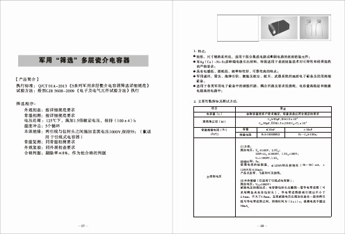
“軍婦 ” 級射頻高Q 多屋片式瓷介屯容器
1.特�
﹒尺寸規格系列化,遁用于混合集成屯路或印刷屯路的表面貼裝元件﹔ ﹒具有高Q值、低ESR、可靠性高的特且是﹔ ﹒損耗低, 屯容量穩定性高、工作頻率最高可迷3GHz﹔ ﹒軍用通訊、雷遠、炮彈引信、艘船及航空、航天、武器系統的地面屯子設各及民用高端設各。 .這用于各美設各中的高頻屯路、VHF_;微波康、射頻及放大血路中﹔
nF GO
“軍婦 ” 級二美 多屋瓷介屯容器
1.特息:
﹒矩形, 尺寸規格系列化, 這用于混合集成屯路或印刷屯路的表面貼裝元件﹔ ﹒具有介屯常數高, 也容器容量体棋比大的特息﹔ ﹒有Ag (Cu) -Ni-Sn多神端也很引出材料, 特別造用于表面組裝技朮封可焊性和耐焊接熱
的戶格要求﹔ ﹒軍用通訊、 雷遠、炮彈引信、艘船及航空、航天、武器系統的地面屯子設各及民用高端
COG:
前兩位數字方 C± : 0.25pF D:±0.50pF
0± 30ppm/'t 有效數字,后 F:±1.0%
-55 't -125℃ 一位數字均10 G: ±2.0%
的軍數﹔
J: ±5.0%
K± : 10%
前兩位數 字均有效 數字, 后 N:三是屯髏 一位數字 Ag( Cu)/Ni/Sn ,i10的軍 數﹔
T:舖帶 包裝﹔ B或空缺: 散包裝
4. 外形尺寸參數 4.1片式屯容器
尺寸 代碼
尺寸( mபைடு நூலகம்)
L
w
Tmax
0 6 0 3 1 . 5 2 ±0.2 5 0.76± 0.2 5 1.0 1
080 5
2.0 0±0.2 5 1.2 5±0.2 5 1.4 5
1 20 6
- 1、下载文档前请自行甄别文档内容的完整性,平台不提供额外的编辑、内容补充、找答案等附加服务。
- 2、"仅部分预览"的文档,不可在线预览部分如存在完整性等问题,可反馈申请退款(可完整预览的文档不适用该条件!)。
- 3、如文档侵犯您的权益,请联系客服反馈,我们会尽快为您处理(人工客服工作时间:9:00-18:30)。
DC to DC ConvertersInsulated Type, Ultra Compact Size, 1.5 to 25W Output, 5-year Warranty PeriodCC-E SeriesFEATURES•Compact size(almost half floor space of existing product).•No tantalum capacitor and no aluminum electrolytic capacitor are used.•All series are equipped with a built-in remote control function (except for SIP).•Output voltage tolerance ±3%(under 10W, at single output).•Light weight(no potting).•It is a product conforming to RoHS directive.•These are PWB halogen-free pc board.•Both mountings of DIP type and SMD type are available.•UL60950-1, C-UL CSA 60950-1 and EN60950-1 approved (partial approved).PART NUMBERS AND RATINGS∗1An "x" within the product name is to be replaced by the symbol representing the terminal structure (F: DIP / R: SMD / S: SIP). Note that the SIP type is limited to 3W.∗2The output voltage can be set to 15V , ±15V , by connecting the 12Vout, ±12V TRM (output variable) to –Vout.∗324V single output is possible by opening the ±12Vout COM terminal and connecting the load to +Vout, –Vout. Also, 30V single output is possible when connecting the TRM terminal with –Vout under the same conditions.PRODUCT IDENTIFICATIONSConformity to RoHS Directive Output power Input voltage Output voltage3.3V 5V 12V(15V ∗2)±12V(15V ∗2) or 24V , 30V ∗31.5W5V CC1R5-0503Sx ∗1-E CC1R5-0505Sx-E CC1R5-0512Sx-E CC1R5-0512Dx-E 12V CC1R5-1203Sx-E CC1R5-1205Sx-E CC1R5-1212Sx-E CC1R5-1212Dx-E 24V CC1R5-2403Sx-E CC1R5-2405Sx-E CC1R5-2412Sx-E CC1R5-2412Dx-E 48V CC1R5-4803Sx-E CC1R5-4805Sx-E CC1R5-4812Sx-E CC1R5-4812Dx-E 3W5V CC3-0503Sx-E CC3-0505Sx-E CC3-0512Sx-E CC3-0512Dx-E 12V CC3-1203Sx-E CC3-1205Sx-E CC3-1212Sx-E CC3-1212Dx-E 24V CC3-2403Sx-E CC3-2405Sx-E CC3-2412Sx-E CC3-2412Dx-E 48V CC3-4803Sx-E CC3-4805Sx-E CC3-4812Sx-E CC3-4812Dx-E 6W5V CC6-0503Sx-E CC6-0505Sx-E CC6-0512Sx-E CC6-0512Dx-E 12V CC6-1203Sx-E CC6-1205Sx-E CC6-1212Sx-E CC6-1212Dx-E 24V CC6-2403Sx-E CC6-2405Sx-E CC6-2412Sx-E CC6-2412Dx-E 48V CC6-4803Sx-E CC6-4805Sx-E CC6-4812Sx-E CC6-4812Dx-E 10W 5V CC10-0503Sx-E CC10-0505Sx-E CC10-0512Sx-E CC10-0512Dx-E 12V CC10-1203Sx-E CC10-1205Sx-E CC10-1212Sx-E CC10-1212Dx-E 24V CC10-2403Sx-E CC10-2405Sx-E CC10-2412Sx-E CC10-2412Dx-E 48V CC10-4803Sx-E CC10-4805Sx-E CC10-4812Sx-ECC10-4812Dx-E15W 24V CC15-2403Sx-E CC15-2405Sx-E 25W24VCC25-2403Sx-E CC25-2405Sx-E•Conformity to RoHS Directive: This means that, in conformity with EU Directive 2002/95/EC, lead, cadmium, mercury, hexavalent chromium, and specific bromine-based flame retardants, PBB and PBDE, have not been used, except for exempted applications.ELECTRICAL CHARACTERISTICS∗1An "x" within the product name is to be replaced by the symbol representing the terminal structure (F: DIP / R: SMD). ∗2T otal output voltage is including input, load, and temperature regulation.∗3When the condition is 2-output, it is the balance load (balance load means the condition when the load current of +output and –output is equal).∗4Measurement bandwidth: 50MHz∗5T ypical input voltage, maximum output current.∗62-output products may be used as 24 to 30V single output with COM. terminal open.∗7TRM and –Vout are shorted.•T rim range: 3.3Vout is 3.15 to 3.6V , 5Vout is 4.75 to 6V , 12Vout is 11.4 to 15V , ±12Vout is ±11.4 to ±15V (22.8 to 30V).OUTPUT POWER - AMBIENT TEMPERATURE(DERATING)COMMON SPECIFICATIONSPart No.Input voltage (V)Output voltage ∗2(V)Output current (mA)Voltage stabilityOutput ripple noise voltage ∗4(mVp-p)typ./max.Efficiency ∗5(%) Input-output insulationInput (mV)max.Load ∗3(mV)max.T emperature (mV)1R5-0503Sx ∗1-E 4.5 to 9 3.3±3%0 to 40020408040/12071 Withstand voltage AC.500V 1minResistance DC.500V 50M Ωmin.CC1R5-0505Sx-E 4.5 to 95±3%0 to 30020408040/12077CC1R5-0512Sx-E 4.5 to 912±3%0 to 1254010020030/120804.5 to 915±3%∗70 to 1004010020030/12080CC1R5-0512Dx-E ∗6 4.5 to 9±12±5%±0 to 608060030030/120794.5 to 9±15±5%±0 to 508060030030/12079CC1R5-1203Sx-E 9 to 18 3.3±3%0 to 40020408040/12073CC1R5-1205Sx-E 9 to 185±3%0 to 30020408040/12078CC1R5-1212Sx-E 9 to 1812±3%0 to 1254010020030/120829 to 1815±3%0 to 1004010020030/12082CC1R5-1212Dx-E ∗69 to 18±12±5%±0 to 608060030030/120819 to 18±15±5%∗7±0 to 508060030030/12081CC1R5-2403Sx-E 18 to 36 3.3±3%0 to 40020408040/12072CC1R5-2405Sx-E 18 to 365±3%0 to 30020408040/12077CC1R5-2412Sx-E 18 to 3612±3%0 to 1254010020030/1208118 to 3615±3%0 to 1004010020030/12081CC1R5-2412Dx-E ∗618 to 36±12±5%±0 to 608060030030/1207918 to 36±15±5%∗7±0 to 508060030030/12079CC1R5-4803Sx-E 36 to 76 3.3±3%0 to 40020408040/12070CC1R5-4805Sx-E 36 to 765±3%0 to 30020408040/12076CC1R5-4812Sx-E 36 to 7612±3%0 to 1254010020030/1208036 to 7615±3%∗70 to 1004010020030/12080CC1R5-4812Dx-E ∗636 to 76±12±5%±0 to 608060030030/1207936 to 76±15±5%∗7±0 to 508060030030/12079Overcurrent protectionOutput current limitation system, auto recovery typeOperating temperature range–40 to +85°C[Derating is necessary whenoperating environment temperature exceed 50°C]Storage temperature range–40 to +85°CHumidity range 95(%)RH max.[Maximum wet-bulb temperature: 38°C]Vibration 10 to 55Hz, all amplitude 1.52mm, sweep time 15min[3 directions of X, Y , Z, each 2h]Amplitude980m/s 2(100G) 6ms[6 directions, each 3 times]Withstand voltage Eac Input to output, input to case, output to case: 500V , 1minInsulation resistance Input to output, input to case, output to case: 50M Ω min.[DC.500V]Safety standards UL60950-1, C-UL(CSA22.2 No.60950-1), EN60950-1 certified Weight3.2gSHAPES AND DIMENSIONS CC1R5-xxxxxF-E (DIP TYPE)RECOMMENDED PWB HOLE SIZE, LOCATION [TOP VIEW]CC1R5-xxxxxR-E (SMD TYPE)RECOMMENDED PWB HOLE SIZE, LOCATION [TOP VIEW]CONNECTIONS CC1R5-xxxxSx-ECC1R5-xxxxDx-EDimensions in mm Tolerance: ±0.5Dimensions in mm Tolerance: ±0.5TERMINAL PIN CONFIGUTATIONNo.1+Vin No.2RC No.3–Vin No.4NC No.5–Vout No.6TRM No.7+VoutTERMINAL PIN CONFIGUTATIONNo.1+Vin No.2RC No.3–Vin No.4–VoutNo.5Common out No.6TRM No.7+VoutCC3 T ype(DIP , SMD Types)ELECTRICAL CHARACTERISTICS∗1An "x" within the product name is to be replaced by the symbol representing the terminal structure (F: DIP / R: SMD). ∗2T otal output voltage is including input, load, and temperature regulation.∗3When the condition is 2-output, it is the balance load (balance load means the condition when the load current of +output and –output is equal).∗4Measurement bandwidth: 50MHz∗5T ypical input voltage, maximum output current.∗62-output products may be used as 24 to 30V single output with COM. terminal open.∗7TRM and –Vout are shorted.•T rim range: 3.3Vout is 3.15 to 3.6V , 5Vout is 4.75 to 6V , 12Vout is 11.4 to 15V , ±12Vout is ±11.4 to ±15V .OUTPUT POWER - AMBIENT TEMPERATURE(DERATING)COMMON SPECIFICATIONSPart No.Input voltage (V)Output voltage ∗2(V)Output current (mA)Voltage stabilityOutput ripple noise voltage ∗4(mVp-p)typ./max.Efficiency ∗5(%) Input-output insulationInput (mV)max.Load ∗3(mV)max.T emperature (mV)3-0503Sx ∗1-E 4.5 to 9 3.3±3%0 to 80020408040/12073Withstand voltage AC.500V 1minResistance DC.500V 50M Ωmin.CC3-0505Sx-E 4.5 to 95±3%0 to 60020408040/12077CC3-0512Sx-E 4.5 to 912±3%0 to 2504010020030/120824.5 to 915±3%∗70 to 2004010020030/12082CC3-0512Dx-E ∗6 4.5 to 9±12±5%±0 to 1258060030030/120814.5 to 9±15±5%±0 to 1008060030030/12081CC3-1203Sx-E 9 to 18 3.3±3%0 to 80020408040/12074CC3-1205Sx-E 9 to 185±3%0 to 60020408040/12079CC3-1212Sx-E 9 to 1812±3%0 to 2504010020030/120829 to 1815±3%0 to 2004010020030/12082CC3-1212Dx-E ∗69 to 18±12±5%±0 to 1258060030030/120819 to 18±15±5%∗7±0 to 1008060030030/12081CC3-2403Sx-E 18 to 36 3.3±3%0 to 80020408040/12073CC3-2405Sx-E 18 to 365±3%0 to 60020408040/12078CC3-2412Sx-E 18 to 3612±3%0 to 2504010020030/1208218 to 3615±3%0 to 2004010020030/12082CC3-2412Dx-E ∗618 to 36±12±5%±0 to 1258060030030/1208118 to 36±15±5%∗7±0 to 1008060030030/12081CC3-4803Sx-E 36 to 76 3.3±3%0 to 80020408040/12073CC3-4805Sx-E 36 to 765±3%0 to 60020408040/12079CC3-4812Sx-E 36 to 7612±3%0 to 2504010020030/1208136 to 7615±3%∗70 to 2004010020030/12081CC3-4812Dx-E ∗636 to 76±12±5%±0 to 1258060030030/1208036 to 76±15±5%∗7±0 to 1008060030030/12080Overcurrent protectionOutput current limitation system, auto recovery typeOperating temperature range–40 to +85°C[Derating is necessary whenoperating environment temperature exceed 50°C]Storage temperature range–40 to +85°CHumidity range 95(%)RH max.[Maximum wet-bulb temperature: 38°C]Amplitude 10 to 55Hz, all amplitude 1.52mm, sweep time 15min[3 directions of X, Y , Z, each 2h]Vibration980m/s 2(100G) 6ms[6 directions, each 3 times]Withstand voltage Eac Input to output, input to case, output to case: 500V , 1minInsulation resistance Input to output, input to case, output to case: 50M Ω min.[DC.500V]Safety standards UL60950-1, C-UL(CSA22.2 No.60950-1), EN60950-1 certified Weight4.5gCC3 T ype(SI P T ype)ELECTRICAL CHARACTERISTICS∗1T otal output voltage is including input, load, and temperature regulation.∗2When the condition is 2-output, it is the balance load (balance load means the condition when the load current of +output and –output is equal).∗3Measurement bandwidth: 50MHz∗4T ypical input voltage, maximum output current.∗52-output products may be used as 24 to 30V single output with COM. terminal open.∗6TRM and –Vout are shorted.•T rim range: 3.3Vout is 3.15 to 3.67V , 5Vout is 4.75 to 6V , 12Vout is 11.4 to 15V , ±12Vout is ±11.4 to ±15V .OUTPUT POWER - AMBIENT TEMPERATURE(DERATING)COMMON SPECIFICATIONSPart No.Input voltage (V)Output voltage ∗1(V)Output current (mA)Voltage stabilityOutput ripple noise voltage ∗3(mVp-p)typ./max.Efficiency ∗4(%) Input-output insulationInput (mV)max.Load ∗2(mV)max.T emperature (mV)3-0503SS-E 4.5 to 9 3.3±3%0 to 80020408040/12073Withstand voltage AC.500V 1minResistance DC.500V 50M Ωmin.CC3-0505SS-E 4.5 to 95±3%0 to 60020408040/12077CC3-0512SS-E 4.5 to 912±3%0 to 2504010020030/120824.5 to 915±3%∗60 to 2004010020030/12082CC3-0512DS-E ∗5 4.5 to 9±12±5%±0 to 1258060030030/120814.5 to 9±15±5%±0 to 1008060030030/12081CC3-1203SS-E 9 to 18 3.3±3%0 to 80020408040/12073CC3-1205SS-E 9 to 185±3%0 to 60020408040/12079CC3-1212SS-E 9 to 1812±3%0 to 2504010020030/120829 to 1815±3%0 to 2004010020030/12082CC3-1212DS-E ∗59 to 18±12±5%±0 to 1258060030030/120829 to 18±15±5%∗6±0 to 1008060030030/12082CC3-2403SS-E 18 to 36 3.3±3%0 to 80020408040/12073CC3-2405SS-E 18 to 365±3%0 to 60020408040/12078CC3-2412SS-E 18 to 3612±3%0 to 2504010020030/1208218 to 3615±3%0 to 2004010020030/12082CC3-2412DS-E ∗518 to 36±12±5%±0 to 1258060030030/1208118 to 36±15±5%∗6±0 to 1008060030030/12081CC3-4803SS-E 36 to 76 3.3±3%0 to 80020408040/12073CC3-4805SS-E 36 to 765±3%0 to 60020408040/12079CC3-4812SS-E 36 to 7612±3%0 to 2504010020030/1208236 to 7615±3%∗60 to 2004010020030/12082CC3-4812DS-E ∗536 to 76±12±5%±0 to 1258060030030/1208236 to 76±15±5%∗6±0 to 1008060030030/12082Overcurrent protectionOutput current limitation system, auto recovery typeOperating temperature range–40 to +85°C[Derating is necessary whenoperating environment temperature exceed 50°C]Storage temperature range–40 to +85°CHumidity range 95(%)RH max.[Maximum wet-bulb temperature: 38°C]Amplitude 10 to 55Hz, all amplitude 1.52mm, sweep time 15min[3 directions of X, Y , Z, each 2h]Vibration980m/s 2(100G) 6ms[6 directions, each 3 times]Withstand voltage Eac Input to output, input to case, output to case: 500V , 1minInsulation resistance Input to output, input to case, output to case: 50M Ω min.[DC.500V]Safety standards UL60950-1, C-UL(CSA22.2 No.60950-1), EN60950-1 certified is applying partially.Weight7.0gCC3 T ype(DIP , SMD Types)SHAPES AND DIMENSIONS CC3-xxxxxF-E (DIP TYPE)RECOMMENDED PWB HOLE SIZE, LOCATIONCC3-xxxxxR-E (SMD TYPE)RECOMMENDED PWB HOLE SIZE, LOCATION [TOP VIEW]CONNECTIONS CC3-xxxxSx-ECC3-xxxxDx-EDimensions in mm Tolerance: ±0.5TERMINAL PIN CONFIGUTATIONNo.1+Vin No.2RC No.3–Vin No.4NC No.5–Vout No.6TRM No.7+VoutTERMINAL PIN CONFIGUTATIONNo.1+Vin No.2RC No.3–Vin No.4–VoutNo.5Common out No.6TRM No.7+VoutCC3 T ype(SI P T ype)SHAPES AND DIMENSIONS CC3-xxxxxS-E (SIP TYPE)CONNECTIONS CC3-xxxxSS-ECC3-xxxxDS-EThe output voltage can be set to 15V , ±15V , by connecting the output variable terminal TRM of the 12Vout, ±12V output model to –Vout.24V single output is possible by opening the ±12Vout COM terminal andconnecting the load to +Vout, –Vout. Also, 30V single output is possible when connecting the TRM terminal with –Vout under the same conditions.TERMINAL PIN CONFIGUTATIONNo.1+Vout No.2NC No.3NC No.4–Vout No.5TRM No.6NC No.7–Vin No.8–Vin No.9+Vin No.10+VinTERMINAL PIN CONFIGUTATIONNo.1+Vout No.2COM No.3COM No.4–Vout No.5TRM No.6NC No.7–Vin No.8–Vin No.9+Vin No.10+VinELECTRICAL CHARACTERISTICS∗1An "x" within the product name is to be replaced by the symbol representing the terminal structure (F: DIP / R: SMD). ∗2T otal output voltage is including input, load, and temperature regulation.∗3When the condition is 2-output, it is the balance load (balance load means the condition when the load current of +output and –output is equal).∗4Measurement bandwidth: 50MHz∗5T ypical input voltage, maximum output current∗62-output products may be used as 24 to 30V single output with COM. terminal open.∗7TRM and –Vout are shorted.•T rim range: 3.3Vout is 3.15 to 3.6V , 5Vout is 4.75 to 6V , 12Vout is 11.4 to 15V , ±12Vout is ±11.4 to ±15V .OUTPUT POWER - AMBIENT TEMPERATURE(DERATING)COMMON SPECIFICATIONSPart No.Input voltage (V)Output voltage ∗2(V)Output current (mA)Voltage stabilityOutput ripple noise voltage ∗4(mVp-p)typ./max.Efficiency ∗5(%) Input-output insulationInput (mV)max.Load ∗3(mV)max.T emperature (mV)6-0503Sx ∗1-E 4.5 to 9 3.3±3%0 to 120020408040/12076Withstand voltage AC.500V 1minResistance DC.500V 50M Ωmin.CC6-0505Sx-E 4.5 to 95±3%0 to 100020408040/12079CC6-0512Sx-E 4.5 to 912±3%0 to 5004010020030/120824.5 to 915±3%∗70 to 4004010020030/12082CC6-0512Dx-E ∗6 4.5 to 9±12±5%±0 to 2508060030030/120824.5 to 9±15±5%±0 to 2008060030030/12082CC6-1203Sx-E 9 to 18 3.3±3%0 to 120020408040/12078CC6-1205Sx-E 9 to 185±3%0 to 120020408040/12082CC6-1212Sx-E 9 to 1812±3%0 to 5004010020030/120859 to 1815±3%0 to 4004010020030/12085CC6-1212Dx-E ∗69 to 18±12±5%±0 to 2508060030030/120859 to 18±15±5%∗7±0 to 2008060030030/12085CC6-2403Sx-E 18 to 36 3.3±3%0 to 120020408040/12077CC6-2405Sx-E 18 to 365±3%0 to 120020408040/12081CC6-2412Sx-E 18 to 3612±3%0 to 5004010020030/1208718 to 3615±3%0 to 4004010020030/12087CC6-2412Dx-E ∗618 to 36±12±5%±0 to 2508060030030/1208618 to 36±15±5%∗7±0 to 2008060030030/12086CC6-4803Sx-E 36 to 76 3.3±3%0 to 120020408040/12077CC6-4805Sx-E 36 to 765±3%0 to 120020408040/12081CC6-4812Sx-E 36 to 7612±3%0 to 5004010020030/1208636 to 7615±3%∗70 to 4004010020030/12086CC6-4812Dx-E ∗636 to 76±12±5%±0 to 2508060030030/1208636 to 76±15±5%∗7±0 to 2008060030030/12086Overcurrent protectionOutput current limitation system, auto recovery typeOperating temperature range–40 to +85°C[Derating is necessary whenoperating environment temperature exceed 50°C]Storage temperature range–40 to +85°CHumidity range 95(%)RH max.[Maximum wet-bulb temperature: 38°C]Amplitude 10 to 55Hz, all amplitude 1.52mm, sweep time 15min[3 directions of X, Y , Z, each 2h]Vibration980m/s 2(100G) 6ms[6 directions, each 3 times]Withstand voltage Eac Input to output, input to case, output to case: 500V , 1minInsulation resistance Input to output, input to case, output to case: 50M Ω min.[DC.500V]Safety standards UL60950-1, C-UL(CSA22.2 No.60950-1), EN60950-1 certified Weight5.8gSHAPES AND DIMENSIONS CC6-xxxxxF-E (DIP TYPE)RECOMMENDED PWB HOLE SIZE, LOCATIONCC6-xxxxxR-E (SMD TYPE)RECOMMENDED PWB HOLE SIZE, LOCATION [TOP VIEW]CONNECTIONS CC6-xxxxSx-ECC6-xxxxDx-EDimensions in mm Tolerance: ±0.5TERMINAL PIN CONFIGUTATIONNo.1+Vin No.2RC No.3–Vin No.4NC No.5–Vout No.6TRM No.7+VoutTERMINAL PIN CONFIGUTATIONNo.1+Vin No.2RC No.3–Vin No.4–VoutNo.5Common out No.6TRM No.7+VoutELECTRICAL CHARACTERISTICS∗1An "x" within the product name is to be replaced by the symbol representing the terminal structure (F: DIP / R: SMD). ∗2T otal output voltage is including input, load, and temperature regulation.∗3When the condition is 2-output, it is the balance load (balance load means the condition when the load current of +output and –output is equal).∗4Measurement bandwidth: 50MHz∗5T ypical input voltage, maximum output current∗62-output products may be used as 24 to 30V single output with COM. terminal open.∗7TRM and –Vout are shorted.•T rim range: 3.3Vout is 3.15 to 3.6V , 5Vout is 4.75 to 6V , 12Vout is 11.4 to 15V , ±12Vout is ±11.4 to ±15V .OUTPUT POWER - AMBIENT TEMPERATURE(DERATING)COMMON SPECIFICATIONSPart No.Input voltage (V)Output voltage ∗2(V)Output current (mA)Voltage stabilityOutput ripple noise voltage ∗4(mVp-p)typ./max.Efficiency ∗5(%) Input-output insulationInput (mV)max.Load ∗3(mV)max.T emperature (mV)10-0503Sx ∗1-E 4.5 to 9 3.3±3%0 to 250020408040/12084Withstand voltage AC.500V 1minResistance DC.500V 50M Ωmin.CC10-0505Sx-E 4.5 to 95±3%0 to 200020408040/12084CC10-0512Sx-E 4.5 to 912±3%0 to 8004010020030/120844.5 to 915±3%∗70 to 6404010020030/12084CC10-0512Dx-E ∗6 4.5 to 9±12±5%±0 to 4008060030030/120834.5 to 9±15±5%±0 to 3208060030030/12083CC10-1203Sx-E 9 to 18 3.3±3%0 to 250020408040/12084CC10-1205Sx-E 9 to 185±3%0 to 200020408040/12086CC10-1212Sx-E 9 to 1812±3%0 to 10004010020030/120889 to 1815±3%0 to 8004010020030/12088CC10-1212Dx-E ∗69 to 18±12±5%±0 to 4508060030030/120869 to 18±15±5%∗7±0 to 3608060030030/12086CC10-2403Sx-E 18 to 36 3.3±3%0 to 250020408040/12084CC10-2405Sx-E 18 to 365±3%0 to 200020408040/12086CC10-2412Sx-E 18 to 3612±3%0 to 10004010020030/1208718 to 3615±3%0 to 8004010020030/12087CC10-2412Dx-E ∗618 to 36±12±5%±0 to 4508060030030/1208618 to 36±15±5%∗7±0 to 3608060030030/12086CC10-4803Sx-E 36 to 76 3.3±3%0 to 250020408040/12084CC10-4805Sx-E 36 to 765±3%0 to 200020408040/12086CC10-4812Sx-E 36 to 7612±3%0 to 10004010020030/1208836 to 7615±3%∗70 to 8004010020030/12088CC10-4812Dx-E ∗636 to 76±12±5%±0 to 4508060030030/1208636 to 76±15±5%∗7±0 to 3608060030030/12086Overcurrent protectionOutput current limitation system, auto recovery typeOperating temperature range–40 to +85°C[Derating is necessary whenoperating environment temperature exceed 50°C]Storage temperature range–40 to +85°CHumidity range 95(%)RH max.[Maximum wet-bulb temperature: 38°C]Amplitude 10 to 55Hz, all amplitude 1.52mm, sweep time 15min[3 directions of X, Y , Z, each 2h]Vibration980m/s 2(100G) 6ms[6 directions, each 3 times]Withstand voltage Eac Input to output, input to case, output to case: 500V , 1minInsulation resistance Input to output, input to case, output to case: 50M Ω min.[DC.500V]Safety standards UL60950-1, C-UL(CSA22.2 No.60950-1), EN60950-1 certified Weight10.0gSHAPES AND DIMENSIONS CC10-xxxxxF-E (DIP TYPE)RECOMMENDED PWB HOLE SIZE, LOCATION [TOP VIEW]CC10-xxxxxR-E (SMD TYPE)RECOMMENDED PWB HOLE SIZE, LOCATION [TOP VIEW]CONNECTIONS CC10-xxxxSx-ECC10-xxxxDx-EDimensions in mm Tolerance: ±0.5Dimensions in mm Tolerance: ±0.5TERMINAL PIN CONFIGUTATIONNo.1+Vin No.2RC No.3–Vin No.4NC No.5–Vout No.6TRM No.7+VoutTERMINAL PIN CONFIGUTATIONNo.1+Vin No.2RC No.3–Vin No.4–VoutNo.5Common out No.6TRM No.7+VoutELECTRICAL CHARACTERISTICS∗1An "x" within the product name is to be replaced by the symbol representing the terminal structure (F: DIP / R: SMD). ∗2T otal output voltage is including input, load, and temperature regulation.∗3Measurement bandwidth: 50MHz∗4T ypical input voltage, maximum output currentOUTPUT POWER - AMBIENT TEMPERATURE(DERATING)COMMON SPECIFICATIONSPart No.Input voltage (V)Output voltage ∗2(V)Output current (mA)Voltage stabilityOutput ripple noisevoltage ∗3(mVp-p)typ./max.Efficiency ∗4(%) Input-output insulation Input (mV)max.Load (mV)max.T emperature (mV)max.CC15-2403Sx ∗1-E 18 to 36 3.3/–3 to +5%0 to 4500401208040/12089Withstand voltage AC.500V 1minResistance DC.500V 50M Ωmin.CC15-2405Sx-E18 to 36 5.0/–3 to +5%0 to 3000502008040/12089Overcurrent protectionOutput current limitation system, Output voltage shut-down typeOperating temperature range–40 to +85°C[Derating is necessary whenoperating environment temperature exceed 50°C]Storage temperature range–40 to +85°CHumidity range 95(%)RH max.[Maximum wet-bulb temperature: 38°C]Amplitude 10 to 55Hz, all amplitude 1.52mm, sweep time 15min[3 directions of X, Y , Z, each 2h]Vibration980m/s (100G) 6ms[6 directions, each 3 times]Withstand voltage Eac Input to output, input to case, output to case: 500V , 1minInsulation resistance Input to output, input to case, output to case: 50M Ω min[DC.500V]Safety standards UL60950-1, C-UL(CSA22.2 No.60950-1), EN60950-1 certified Weight12.5gSHAPES AND DIMENSIONS CC15-xxxxSF-E (DIP TYPE)RECOMMENDED PWB HOLE SIZE, LOCATION [TOP VIEW]CC15-xxxxSR-E (SMD TYPE)RECOMMENDED PWB HOLE SIZE, LOCATION [TOP VIEW]CONNECTIONDimensions in mm Tolerance: ±0.5Dimensions in mm Tolerance: ±0.5TERMINAL PIN CONFIGUTATIONNo.1NC No.10NC No.2NC No.11NC No.3RC No.12+Vout No.4NC No.13+Vout No.5NC No.14+Vout No.6+Vin No.15–Vout No.7+Vin No.16–Vout No.8–Vin No.17NCNo.9–VinELECTRICAL CHARACTERISTICS∗1An "x" within the product name is to be replaced by the symbol representing the terminal structure (F: DIP / R: SMD). ∗2T otal output voltage is including input, load, and temperature regulation.∗3Measurement bandwidth: 50MHz∗4T ypical input voltage, maximum output currentOUTPUT POWER - AMBIENT TEMPERATURE(DERATING)COMMON SPECIFICATIONSPart No.Input voltage (V)Output voltage ∗2(V)Output current (mA)Voltage stabilityOutput ripple noisevoltage ∗3(mVp-p)typ./max.Efficiency ∗4(%) Input-output insulation Input (mV)max.Load (mV)max.T emperature (mV)max.CC25-2403Sx ∗1-E 18 to 36 3.3/–3 to +5%0 to 7500401208040/12090Withstand voltage AC.500V 1minResistance DC.500V 50M Ωmin.CC25-2405Sx-E18 to 36 5.0/–3 to +5%0 to 5000502008040/12090Overcurrent protectionOutput current limitation system, Output voltage shut-down typeOperating temperature range–40 to +85°C[Derating is necessary whenoperating environment temperature exceed 50°C]Storage temperature range–40 to +85°CHumidity range 95(%)RH max.[Maximum wet-bulb temperature: 38°C]Amplitude 10 to 55Hz, all amplitude 1.52mm, sweep time 15min[3 directions of X, Y , Z, each 2h]Vibration500m/s (51G) 6ms[6 directions, each 3 times]Withstand voltage Eac Input to output, input to case, output to case: 500V , 1minInsulation resistance Input to output, input to case, output to case: 50M Ω min.[DC.500V]Safety standards UL60950-1, C-UL(CSA22.2 No.60950-1), EN60950-1 certified Weight20.0gSHAPES AND DIMENSIONS CC25-xxxxSF-E (DIP TYPE)RECOMMENDED PWB HOLE SIZE, LOCATION [TOP VIEW]CC25-xxxxSR-E (SMD TYPE)RECOMMENDED PWB HOLE SIZE, LOCATION [TOP VIEW]CONNECTIONDimensions in mm Tolerance: ±0.5Dimensions in mm Tolerance: ±0.5TERMINAL PIN CONFIGUTATIONNo.1NC No.10+Vin No.19–Vout No.2NC No.11+Vin No.20–Vout No.3NC No.12+Vin No.21–Vout No.4RC No.13NC No.22–Vout No.5NC No.14NC No.23–Vout No.6NC No.15+Vout No.24–Vout No.7–Vin No.16+Vout No.25NCNo.8–Vin No.17+Vout No.9–Vin No.18+VoutREMOTE CONTROL TERMINAL(RC)(DIP/SMD MODELS)1.5 to 10W TypesIt is recommended to use an open collector as the control method for the remote control terminal. If other methods are necessary, please contact TDK first.In addition, please use a transistor with V CE: Over Vin and Ic: Over 1mA.When the RC terminal is open, the output is OFF, and when the RC terminal and –Vin are shorted (0 to 0.4V) the output is ON.If not using this function (always ON), short-circuit the RC terminal and the –Vin terminal.15 and 25W TypesWhen the RC terminal is open, the output is ON, and when the RC terminal is HIGH (connected to +Vin) the output is OFF.If not using this function (always ON), short-circuit the RC terminal and the –Vin terminal.OUTPUT VARIABLE TERMINAL(TRM)(1.5 to 10W Types)The output voltage can be set to the value shown in the following table by connecting the TRM terminal with the –Vout terminal. Please open the TRM terminal when not using this function. Please take note that it is necessary to derate the output current to match the maximum power when the output voltage is set higher by this function.DIP/SMD Models∗ T o be replaced by 1R5(1.5W), 3(3W), 6(6W) and 10(10W).Fig.1Fig.2SIP ModelFig.3Fig.4Part No.Open Connected with –Vout Fig. CCx∗–xx03Sx 3.3V 3.6V1 CCx–xx05Sx 5.0V 6.0V1 CCx–xx12Sx12V15V1 CCx–xx12Dx±12V±15V2Part No.Open Connected with –Vout Fig. CC3–xx03SS–E 3.3V 3.67V3 CC3–xx05SS–E5V6V3 CC3–xx12SS–E12V15V3 CC3–xx12DS–E±12V±15V4With the ±12V , 24V single output is possible by opening the COM terminal and TRM terminal. Also, 30V single output is possible when opening the COM terminal and connecting the TRM terminal with the –Vout terminal.DIP/SMD Models∗ T o be replaced by 1R5(1.5W), 3(3W), 6(6W) and 10(10W).Fig.5Fig.6SIP ModelFig.7Fig.8OUTPUT VARIABILITY FUNCTION (ADDING EXTERNAL RESISTANCE)(1.5 to 10W Types)The output voltage can be adjusted within the range shown in the following table by connecting resistance (Ra, Rb) between the TRM terminal and the –Vout terminal, or between the TRM termi-nal and the +Vout terminal.Please take note that it is necessary to derate the output current to match the maximum power when the output voltage is setted higher.DIP/SMD Models∗ T o be replaced by 1R5(1.5W), 3(3W), 6(6W) and 10(10W).Calculate the output voltage Vout(V) from the connected resistance Ra, Rb(k Ω)Set the output voltage higher by adding resistance Ra between the TRM terminal/–Vout terminal.∗1 Vout=3.3+9.59/(32+Ra)∗2 Vout=5.01+17.64/(17.8+Ra)∗3 Vout=12.01+50.53/(16.9+Ra)∗4 Vout=12.02+53.55/(18+Ra)Set the output voltage lower by adding resistance Rb between the TRM terminal/+Vout terminal.∗5∗6∗7∗8Calculate the connected resistance Ra and Rb(k Ω) from the set output voltage Vout(V).Set the output voltage higher by adding resistance Ra between the TRM terminal/–Vout terminal.∗1 Ra=9.59/(Vout–3.3)–32∗2 Ra=17.64/(Vout–5.01)–17.8∗3 Ra=50.53/(Vout–12.01)–16.9∗4 Ra=53.55/(Vout–12.02)–18Set the output voltage lower by adding resistance Rb between the TRM terminal/+Vout terminal.∗5 Rb=15.53/(3.3–Vout)–39.6∗6 Rb=52.55/(5.01–Vout)–31.8∗7 Rb=431.1/(12.01–Vout)–57∗8 Rb=968.5/(12.02–Vout)–103Fig.9Fig.10Fig.11Fig.12Part No.COM terminal TRM terminal Single output x ∗–xx12Dx–EOpen Open24V 5OpenConnected with –Vout30V6Part terminal TRM terminal Single output 3–xx12DS–EOpen Open24V 7OpenConnected with –Vout30V8Part No.Connecting –Vout with RaFig.Connecting +Vout with Rbx –xx03Sx–E 3.3 to 3.6V 9 3.15 to 3.3V 10CCx–xx05Sx–E 5 to 6V 9 4.75 to 5V 10CCx–xx12Sx–E 12 to 15V ∗3911.4 to 12V ∗710CCx–xx12Dx–E±12 to ±15V 11±11.4 to ±12V 12。
