WP710A10NT;中文规格书,Datasheet资料
龙芯7a2000独显桥片数据手册说明书
龙芯7A2000独显桥片数据手册V1.12022年10月龙芯中科技术股份有限公司版权声明本文档版权归龙芯中科技术股份有限公司所有,并保留一切权利。
未经书面许可,任何公司和个人不得将此文档中的任何部分公开、转载或以其他方式散发给第三方。
否则,必将追究其法律责任。
免责声明本文档仅提供阶段性信息,所含内容可根据产品的实际情况随时更新,恕不另行通知。
如因文档使用不当造成的直接或间接损失,本公司不承担任何责任。
龙芯中科技术股份有限公司Loongson Technology Corporation Limited地址:北京市海淀区中关村环保科技示范园龙芯产业园2号楼Building No.2, Loongson Industrial Park, Zhongguancun Environmental Protection Park电话(Tel):************传真(Fax):************阅读指南《龙芯7A2000独显桥片数据手册》主要介绍龙芯7A2000独显桥片接口结构,特性,电气规范,以及硬件设计指导。
版本信息手册信息反馈: *******************目录版本信息 (5)图目录.............................................................................................................................................. I II 表目录. (IV)附录目录 (V)1.简介 (1)1.1技术指标 (1)1.2典型应用 (2)1.2.1单路应用 (2)1.2.2双路应用 (3)1.3订购信息 (4)1.4术语 (4)1.5文档约定 (4)1.5.1引脚信号命名 (4)1.5.2数值表示 (5)1.5.3寄存器域 (5)2.接口信号 (6)2.1信号类型定义 (6)2.2接口信号说明 (6)2.2.1HT接口 (6)2.2.2PCIE接口 (8)2.2.3显存接口 (9)2.2.4网络接口 (9)2.2.5SATA接口 (10)2.2.6VGA接口 (10)2.2.7HDMI接口 (11)2.2.8USB接口 (11)2.2.9HDA接口 (12)2.2.10SPI接口 (12)2.2.11LPC接口 (12)2.2.12I2C接口 (13)2.2.13UART接口 (13)2.2.14PWM接口 (13)2.2.15GPIO接口 (13)2.2.16RTC信号 (14)2.2.17电源管理接口 (14)2.2.18时钟信号 (15)2.2.19芯片配置接口 (15)2.2.20中断接口 (16)2.2.21JTAG接口 (17)2.2.22引脚复用表 (17)3.功能及接口说明 (20)3.1 HT接口 (20)3.2 PCIE接口 (20)3.3 GPU (20)3.4 显示接口 (20)3.5 显存接口 (21)3.6 USB接口 (21)3.7 SATA接口 (21)3.8 网络接口 (22)3.9 HDA接口 (22)3.10 I2S接口 (22)3.11 SPI接口 (22)3.12 LPC接口 (23)3.13 UART接口 (23)3.14CAN (23)3.15 I2C接口 (23)3.16 PWM (24)3.17HPET (24)3.18 RTC (24)3.19 ACPI接口 (24)3.20 GPIO接口 (25)3.21 JTAG接口 (25)4.时钟 (26)4.1时钟内部框图 (26)4.2芯片时钟介绍 (26)4.3时钟功能描述 (27)4.4频率配置 (28)5.电源管理ACPI (29)5.1电源域 (29)5.2功能描述 (29)6.热设计 (30)6.1热参数 (30)6.2焊接温度及焊接曲线 (30)7.电气特性 (32)7.1最大额定工作条件 (32)7.2工作电源 (33)7.3典型应用功耗 (34)7.4电源时序 (36)7.4.1使能ACPI_EN (36)7.4.2不使能ACPI_EN (43)8.封装信息 (46)8.1封装尺寸 (46)8.2信号位置分布 (48)8.3芯片引脚排布 (48)9.产品标识 (49)附录A:芯片引脚排布图 (50)图1-1 龙芯7A2000顶层结构图 (1)图1-2单路应用示意图 (3)图1-3双路应用示意图 (3)图4-1芯片时钟结构图 (26)图6-1焊接回流曲线 (31)图7-1冷启动上电时序(RTC掉电) (36)图7-2热复位时序图 (38)图7-3 S0到S3及S3到S0时序图 (40)图7-4 S0到S4/S5及S4/5到S0状态时序图 (41)图7-5 不使能ACPI功能时的冷启动上电时序(RTC掉电) (43)图7-6 不使能ACPI功能时的热复位时序图 (44)图8-1 封装尺寸 (46)图8-2 DIE位置 (47)图8-3信号引脚分布总览(顶视图) (48)图9-1 产品标识 (49)表1-1龙芯7A2000芯片分级 (4)表1-2术语和缩略语表 (4)表2-1信号类型说明 (6)表2-2 HT接口 (6)表2-3 PCIE接口 (8)表2-4 显存接口 (9)表2-5 网络接口 (9)表2-6 SATA接口 (10)表2-7 VGA接口 (10)表2-8 HDMI接口 (11)表2-9 USB接口 (11)表2-10 HDA接口 (12)表2-11 SPI接口 (12)表2-12 LPC接口 (12)表2-13 I2C接口 (13)表2-14 UART接口 (13)表2-15 PWM接口 (13)表2-16 GPIO接口 (13)表2-17 RTC接口 (14)表2-18 电源管理接口 (14)表2-19 时钟信号 (15)表2-20 芯片配置接口 (15)表2-21 中断接口 (16)表2-22 JTAG接口 (17)表2-23引脚复用表 (17)表4-1桥片时钟输入 (27)表4-2桥片时钟输出 (27)表6-1龙芯7A2000的热阻参数 (30)表6-2回流焊接温度分类表 (30)表7-1芯片绝对最大额定电压 (32)表7-2工作电源要求 (33)表7-3典型应用功耗 (34)表7-4上电时序要求(示例) (37)表7-5热复位时序约束 (38)表7-6 S0到S3/S4/S5及S3/S4/S5到S0状态时序约束 (42)表7-7 不使能ACPI功能时的上电时序要求 (44)表7-8 不使能ACPI功能时的热复位时序约束 (44)附录目录图A -1芯片引脚排布1/4(顶视图,从左至右) (51)图A -2芯片引脚排布2/4(顶视图,从左至右) (52)图A -3芯片引脚排布3/4(顶视图,从左至右) (53)图A -4芯片引脚排布4/4(顶视图,从左至右) (54)1.简介龙芯7A2000型处理器独显桥片(后文也简称为7A2000)是龙芯7A1000的升级产品。
易欣达7寸数字京东方屏规格书
Shenzhen Digital Technology Co.,ltd.PRODUCTSPECIFICATIONPRODUCT TYPE:7.0” TFT , Transmissive typeMODEL NO:Y81287VERSION:01DATE:2011.05.05Customer ApprovedCustomer:Project name:Approved by:Dept:Data:Designer QC Confirmed ApprovedShenzhen Digital Technology Co.,ltd.5F,43Bldgm Baotian Industrial Area,Xixiang,Baoan District,ShenZhen ChinaTel:(+86)755-61113669/71/72/73Fax:(+86)755-61113619RECORDS OF REVISIONDESCRIPTIONS DATE Version REVISEDISSUE2011.05.05 01FIRST深圳市德智欣科技有限公司CONTENTS1. GENERAL DESCRIPTION - - - - - - - - - - - - - - - - - - - - - - - - - -2. MECHANICAL SPECIFICATIONS - - - - - - - - - - - - - - - - -- - - - - - - -3. OUTLINE DIMENSIONS - - - - - - - - - - - - - - - - - - - - -4. INTERFACE ASSIGNMENT - - - - - - - - - - - - - - - - - - - - - - - - --------5. TIMING CHARACTERISTICS - - - - - - - - - - - - - - - - - - - - - - - ------------------------------------------------6. RESETTIMINGCHARACTERISTICS7. POWER ON/OFF SEQUENCE - - - - - - - - - - - - - - - - - - - - - - - - - - -8. INSTRUCTION TABLE - - - - - - - - - - - - - - - - - - - - - - - - - - -9. ELECTRICAL CHARACTERISTICS - - - - - - - - - - - - - - - - - - - - -10. LED BACKLIGHT CHARACTERISTICS - - - - - - - - - - - - - - - - - - -11. OPTICAL CHARACTERISTICS - - - - - - - - - - - - - - - - - - - - - - - - - -Condition -----------------------------------------------------------12. Reliability13. Inspection Standards ----------------------------------------------------14. Precaution - - - - - - - - - - - - - - - - - - - - - - - -深圳市德智欣科技有限公司1.GENERAL DESCRIPTIONThis LCM Y81287 is a 800 x 3RGB x 480 dots matrix 7.0 ”TFT LCD module. It has a TFTpanel,composed of 1200 -channel source driver and 960-channel gate driver.2. MECHANICAL SPECIFICATIONSUNIT Item Contents LCD Type 7.0” TFT-LCD, TransmissiveOutline Dimension 100(W)x164.9(H)x3.4(T) mmActive Area 85.92(W) x151.68(H) mmViewing direction 6 O’CLOCK ---Source HX8664BDriver ICGate IC HX8264DDisplay Color 16MNumber of Dots 800(RGB)x480 DotsDot Pitch (H×V)0.0642(W) x 0.1790(H) mmAssy Type COG+FPC+BL ---BACKLIGHT WHITE LED Backlight -Interface24 bit interfaceWEIGHT TBD g深圳市德智欣科技有限公司4. INTERFACE ASSIGNMENTPIN NO. SYMBOL1 Power for LED backlighr (Anode) LEDA2 Power for LED backlighr (Anode) LEDA3 Power for LED backlighr (Cathode) LEDK4 Power for LED backlighr (Cathode) LEDKground GND5 Powervoltage VCOM6 Common7 Power for Digital Circuit DVDDmodeselect MODE8 DE/SYNC9 Data input Enable DE10 Vertical Sync Input VS11 Horizontal Sync Input HS12~19 Blue data B7~B020~27 Green data G7~G028~35 Red data R7~R036 Power ground GND37 Sample clock DCLK38 Power ground GND39 Left / right selection L/R40 Up/down selection U/D41 Gate NO Voltage VGH42 Gate OFF Voltage VGL43 Power for Analog Circuit A VDD44 Global reser pin RESET45 No connection NC46 Common Voltage VCOM47 Dithering function DITHB48 Power ground GND49 No connection NC50 No connection NC深圳市德智欣科技有限公司5.TIMING CHARACTERISTICS深圳市德智欣科技有限公司6.RESET TIMING CHARACTERISTICS深圳市德智欣科技有限公司7. POWER ON/OFF SEQUENCE深圳市德智欣科技有限公司8. HX8664B&HX8264D INSTRUCTION TABLE9. ELECTRICAL CHARACTERISTICS深圳市德智欣科技有限公司深圳市德智欣科技有限公司12. Reliability Condition13.Inspection Standards 13.1 Major DefectItem NoItems to be inspected Inspection Standard Classification of defects13.1.1 Allfunctional defects1)No display2) Display abnormally3) Missing vertical, horizontal segment 4) Short circuit5)Back-light no lighting flickering and abnormal lighting.13.1.2 Missing Missing component13.1.3 OutlinedimensionOverall outline dimension beyond the drawing is not allowed.Major13.2 Cosmetic defectItem No Item ConditionRemark1 High temperatureOperating 70°C ±2°C for 240 hours2 Low temperatureOperating -20°C ±2°C for 240 hours3 High temperatureStorage 80°C ±2°C for 240 hours4 Low temperatureStorage -30°C ±2°C for 240hours5High temperature & humidity Storage50℃±5°C , 90%RH, 120 hours 6Thermal Shock Storage (No operation)-20℃ , 30min.<=> 70℃ , 30min.10 Cycles7 ESD test-8 Vibration test 10 => 55 =>10 Hz, within 1 minute;Amplitude:1.5mm.15 minutes for each Direction ( X,Y ,Z ) 9 Drop testPacked, 100CM free fall6 sides, 1 corner, 3edgesNO DEFECT IN DISPLAYING AND OPERATIONAL FUNCTION深圳市德智欣科技有限公司(i) chips on cornerX Y Z ≤2.0≤SDisregardNotes:S=contact pad lengthChips on the corner of terminal shall not be allowed to extend intothe ITO pad or expose perimeter seal. Minor(ii)Usual surface cracksX Y Z≤3.0<Inner border line of the seal DisregardMinor13.3.1Glass defect(iii)CrackCracks tend to break are not allowed.Major13.3.2 Partsalignment1) Not allow IC and FPC/heat-seal lead width is more than 50 %beyond lead pattern.2) Not allow chip or solder component is off center more than 50 % of the pad outline. 13.3.3 SMTAccording to the <Acceptability of electronic assemblies>IPC-A-610C class 2 standard. Component missing or function defect are Major defect, the others are Minor defect.Major14. Precaution14.1 Handling(1) Protect the panel from static, it may cause damage to the CMOS Gate Array IC.(2) Use fingerstalls with soft gloves in order to keep display clean during the incominginspection and assembly process.(3) If the liquid crystal material leaks from the panel, it should be kept away from theeyes or mouth. In case of contact with hands, legs or clothes, it must be washedaway thoroughly with soap.(4) The desirable cleaners are water, IPA (Isopropyl Alcohol) or Hexane. Don’t useKetone type materials (ex. Acetone), Ethyl alcohol, Toluene, Ethyl acid or Methylchloride. It might permanent damage to the polarizer due to chemical reaction.(5) Pins of I/F connector shall not be touched directly with bare hands.(6) Refrain from strong mechanical shock and / or any force to the panel. In addition todamage, this may cause improper operation or damage to the panel.(7) Note that polarizers are very fragile and could be easily damaged. Do not press orscratch the surface harder than a B pencil lead.(8) Wipe off water droplets or oil immediately. If you leave the droplets for a long time,staining and discoloration may occur.(9) If the surface of the polarizer is dirty, clean it using some absorbent cotton or soft cloth.14.2 Storage(1) Do not leave the panel in high temperature, and high humidity for a long time. It ishighly recommended to store the panel with temperature from 0 to 35℃ andrelative humidity of less than 70%.(2) The panel shall be stored in a dark place. It is prohibited to apply sunlight orfluorescent light during the store.14.3 Operation(1) The LCD shall be operated within the limits specified. Operation at values outside ofthese limits may shorten life, and/or harm display images.(2) Do not exceed the absolute maximum rating value. (the supply voltage variation,Input voltage variation in part contents and environmental temperature and so on).Otherwise the panel may be damaged.(3) If the panel displays the same pattern continuously for a long period of time, it canbe the situation when the image” Sticks” to the screen.深圳市德智欣科技有限公司。
VNP10N07中文资料
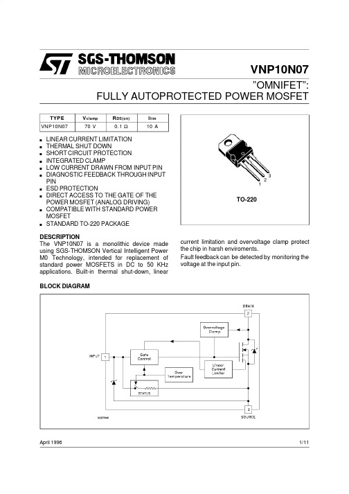
VNP10N07”OMNIFET”:FULLY AUTOPROTECTED POWER MOSFETApril 1996123TO-220BLOCK DIAGRAMTYPE V clamp R DS(on)I l im VNP10N0770V0.1Ω10As LINEAR CURRENT LIMITATION s THERMAL SHUT DOWNs SHORT CIRCUIT PROTECTION s INTEGRATED CLAMPs LOW CURRENT DRAWN FROM INPUT PIN sDIAGNOSTIC FEEDBACK THROUGH INPUT PINs ESD PROTECTIONsDIRECT ACCESS TO THE GATE OF THE POWER MOSFET (ANALOG DRIVING)sCOMPATIBLE WITH STANDARD POWER MOSFETsSTANDARD TO-220PACKAGEDESCRIPTIONThe VNP10N07is a monolithic device made using SGS-THOMSON Vertical Intelligent Power M0Technology,intended for replacement of standard power MOSFETS in DC to 50KHz applications.Built-in thermal shut-down,linear current limitation and overvoltage clamp protect the chip in harsh enviroments.Fault feedback can be detected by monitoring the voltage at the input pin.1/11ABSOLUTE MAXIMUM RATINGSymbol Parameter Value Unit V DS Drain-source Voltage(V in=0)Internally Clamped V V in Input Voltage18VI D Drain Current Internally Limited AI R Reverse DC Output Current-14AV esd Electrostatic Discharge(C=100pF,R=1.5KΩ)2000V P to t Total Dissipation at T c=25o C50W T j Operating Junction Temperature Internally Limited o C T c Case Operating Temperature Internally Limited o C T st g Storage Temperature-55to150o CTHERMAL DATAR t hj-ca se R t hj-amb Thermal Resistance Junction-case MaxThermal Resistance Junction-ambient Max2.562.5o C/Wo C/WELECTRICAL CHARACTERISTICS(T case=25o C unless otherwise specified)OFFSymbol Parameter Test Conditions Min.Typ.Max.Unit V CLAMP Drain-source ClampVoltageI D=200mA V in=0607080VV CLTH Drain-source ClampThreshold VoltageI D=2mA V in=055VV I NCL Input-Source ReverseClamp VoltageI in=-1mA-1-0.3VI DSS Zero Input VoltageDrain Current(V in=0)V DS=13V V in=0V DS=25V V in=050200µAµAI I SS Supply Current fromInput PinV DS=0V V in=10V250500µA ON(∗)Symbol Parameter Test Conditions Min.Typ.Max.Unit V IN(th)Input ThresholdVoltageV DS=V in I D+Ii n=1mA0.83VR DS(on)Static Drain-source OnResistance V i n=10V I D=5AV i n=5V I D=5A0.10.14ΩΩDYNAMICSymbol Parameter Test Conditions Min.Typ.Max.Unitg fs(∗)ForwardTransconductanceV DS=13V I D=5A68SC oss Output Capacitance V DS=13V f=1MHz V in=0350500pF VNP10N072/11ELECTRICAL CHARACTERISTICS(continued)SWITCHING(∗∗)Symbol Parameter Test Conditions Min.Typ.Max.Unitt d(on) t r t d(of f) t f Turn-on Delay TimeRise TimeTurn-off Delay TimeFall TimeV DD=15V I d=5AV gen=10V R gen=10Ω(see figure3)5080230100100160400180nsnsnsnst d(on) t r t d(of f) t f Turn-on Delay TimeRise TimeTurn-off Delay TimeFall TimeV DD=15V I d=5AV gen=10V R gen=1000Ω(see figure3)6000.93.81.7900262.5nsµsµsµs(di/dt)on Turn-on Current Slope V DD=15V I D=5AV i n=10V R gen=10Ω60A/µs Q i Total Input Charge V DD=12V I D=5A V in=10V30nC SOURCE DRAIN DIODESymbol Parameter Test Conditions Min.Typ.Max.Unit V SD(∗)Forward On Voltage I SD=5A V in=0 1.6Vt r r(∗∗) Q r r(∗∗) I RRM(∗∗)Reverse RecoveryTimeReverse RecoveryChargeReverse RecoveryCurrentI SD=5A di/dt=100A/µsV DD=30V T j=25o C(see test circuit,figure5)1250.34.8nsµCAPROTECTIONSymbol Parameter Test Conditions Min.Typ.Max.UnitI lim Drain Current Limit V i n=10V V DS=13VV i n=5V V DS=13V 7710101414AAt dl im(∗∗)Step ResponseCurrent Limit V i n=10VV i n=5V20503080µsµsT jsh(∗∗)OvertemperatureShutdown150o C T j rs(∗∗)Overtemperature Reset135o CI gf(∗∗)Fault Sink Current V i n=10V V DS=13VV i n=5V V DS=13V 5020mAmAE as(∗∗)Single PulseAvalanche Energy starting T j=25o C V DD=20VV i n=10V R gen=1KΩL=10mH0.4J(∗)Pulsed:Pulse duration=300µs,duty cycle1.5%(∗∗)Parameters guarant eed by design/c haracterizationVNP10N073/11During normal operation,the Input pin is electrically connected to the gate of the internal power MOSFET.The device then behaves like a standard power MOSFET and can be used as a switch from DC to50KHz.The only difference from the user’s standpoint is that a small DC current(I iss)flows into the Input pin in order to supply the internal circuitry.The device integrates:-OVERVOLTAGE CLAMP PROTECTION: internally set at70V,along with the rugged avalanche characteristics of the Power MOSFET stage give this device unrivalled ruggedness and energy handling capability. This feature is mainly important when driving inductive loads.-LINEAR CURRENT LIMITER CIRCUIT:limits the drain current Id to Ilim whatever the Input pin voltage.When the current limiter is active, the device operates in the linear region,so power dissipation may exceed the capability of the heatsink.Both case and junction temperatures increase,and if this phase lasts long enough,junction temperature may reach the overtemperature threshold T jsh.-OVERTEMPERATURE AND SHORT CIRCUIT PROTECTION:these are based on sensing the chip temperature and are not dependent on the input voltage.The location of the sensing element on the chip in the power stage area ensures fast,accurate detection of the junction temperature.Overtemperature cutout occurs at minimum150o C.The device is automatically restarted when the chip temperature falls below135o C.-STATUS FEEDBACK:In the case of an overtemperature fault condition,a Status Feedback is provided through the Input pin. The internal protection circuit disconnects the input from the gate and connects it instead to ground via an equivalent resistance of100Ω. The failure can be detected by monitoring the voltage at the Input pin,which will be close to ground potential.Additional features of this device are ESD protection according to the Human Body model and the ability to be driven from a TTL Logic circuit(with a small increase in R DS(on)).PROTECTION FEATURES VNP10N074/11Thermal ImpedanceOutput CharacteristicsStatic Drain-Source On Resistance vs Input Voltage Derating CurveTransconductanceStatic Drain-Source On ResistanceVNP10N075/11Static Drain-Source On Resistance Capacitance VariationsNormalized On Resistance vs Temperature Input Charge vs Input Voltage Normalized Input Threshold Voltage vs TemperatureNormalized On Resistance vs TemperatureVNP10N07 6/11Turn-on Current SlopeTurn-off Drain-Source Voltage Slope Switching Time Resistive Load Turn-on Current SlopeTurn-off Drain-Source Voltage SlopeSwitching Time Resistive LoadVNP10N077/11Switching Time Resistive Load Step Response Current Limit Current Limit vs Junction Temperature Source Drain Diode Forward CharacteristicsVNP10N07 8/11Fig.2:Unclamped Inductive WaveformsFig.3:Switching Times Test Circuits For Resistive Load Fig.4:Input Charge Test CircuitFig.1:Unclamped Inductive Load Test CircuitsFig.5:Test Circuit For Inductive Load Switching And Diode Recovery Times Fig.6:WaveformsVNP10N079/11DIM.mminch MIN.TYP.MAX.MIN.TYP.MAX.A 4.40 4.600.1730.181C 1.23 1.320.0480.051D 2.402.720.0940.107D1 1.270.050E 0.490.700.0190.027F 0.610.880.0240.034F1 1.14 1.700.0440.067F2 1.14 1.700.0440.067G 4.95 5.150.1940.203G1 2.4 2.70.0940.106H210.010.400.3930.409L216.40.645L413.014.00.5110.551L5 2.65 2.950.1040.116L615.2515.750.6000.620L7 6.2 6.60.2440.260L9 3.5 3.930.1370.154DIA.3.75 3.850.1470.151L6ACDED 1FGL7L2Dia.F 1L5L4H 2L9F 2G 1TO-220MECHANICAL DATAP011CVNP10N0710/11元器件交易网VNP10N07 Information furnished is believed to be accurate and reliable.However,SGS-THOMSON Microelectronics assumes no responsabilit y for theconsequences of use of such information nor for any infringemen t of patents or other rights of third parties which may results from its use.Nolicense is granted by implication or otherwise under any patent or patent rights of SGS-THOMSON Microelectr onics.Specifications mention edin this publication are subject to change without notice.This publication supersede s and replaces all information previously supplied.SGS-THOMSON Microelectr onics products are not auth orized for use as critical compon ents in life support devices or systems without expre sswritten approval of SGS-THOMSON Microelectonics.©1996SGS-THOMSON Microelectronics-Printed in Italy-All Rights Reserve dSGS-THOMSON Microelectronics GROUP OF COMPANIESAustralia-Brazil-Canada-China-France-Germany-Hong Kong-Italy-Japan-Korea-Malaysia-Malta-Morocco-The Netherlands-Singapore-Spain-Sweden-Switzerland-Taiwan-Thailand-United Kingdom-U.S.A.11/11。
ZXMP10A17E6TA;中文规格书,Datasheet资料

(Note 1)
(Note 2) (Note 1) (Note 2)
Symbol PD
RθJA TJ, TSTG
Value 1.1 8.8 1.7 13.7 113 73
-55 to 150
Unit W mW/°C
°C/W °C
Notes:
1. For a device surface mounted on 25mm x 25mm x 1.6mm FR4 PCB with high coverage of single sided 1oz copper, in still air conditions; the device is measured when operating in a steady-state condition.
3 of 8
December 2009
© Diodes Incorporated
ADVANCE INFORMATION
A Product Line of Diodes Incorporated
ZXMP10A17E6
Electrical Characteristics @TA = 25°C unless otherwise specified
ADVANCE INFORMATION
A Product Line of Diodes Incorporated
ZXMP10A17E6
100V P-CHANNEL ENHANCEMENT MODE MOSFET
Please click here to visit our online spice models database.
Thermal Characteristics
A Product Line of Diodes Incorporated
10A45芯片的中文版规格书,
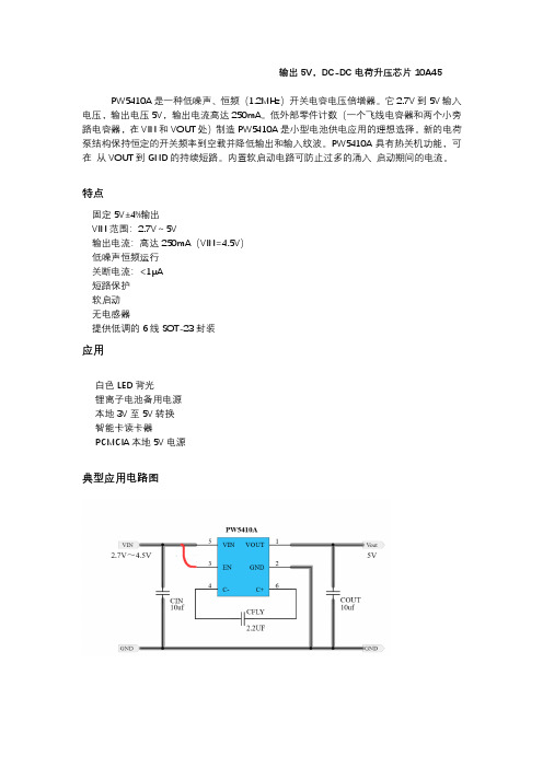
输出5V,DC-DC电荷升压芯片10A45PW5410A是一种低噪声、恒频(1.2MHz)开关电容电压倍增器。
它2.7V到5V输入电压,输出电压5V,输出电流高达250mA。
低外部零件计数(一个飞线电容器和两个小旁路电容器,在VIN和VOUT处)制造PW5410A是小型电池供电应用的理想选择。
新的电荷泵结构保持恒定的开关频率到空载并降低输出和输入纹波。
PW5410A具有热关机功能,可在从VOUT到GND的持续短路。
内置软启动电路可防止过多的涌入启动期间的电流。
特点固定5V±4%输出VIN范围:2.7V~5V输出电流:高达250mA(VIN=4.5V)低噪声恒频运行关断电流:<1μA短路保护软启动无电感器提供低调的6线SOT-23封装应用白色LED背光锂离子电池备用电源本地3V至5V转换智能卡读卡器PCMCIA本地5V电源典型应用电路图PIN脚脚位布局注意事项由于其高开关频率和PW5410A产生的高瞬态电流,必须仔细布局。
一个真正的接地平面和与所有电容器的短连接将提高性能,确保在任何情况下都能正确调节。
操作PW5410A使用开关电容电荷泵提高到可调节的输出电压。
调节是通过一个内部电阻分压器和根据错误信号调制电荷泵输出电流。
在关机模式下,所有电路关闭,PW5410A只从VIN供应。
此外,VOUT与VIN断开。
EN引脚是一个带有阈值电压约为0.8V。
施加逻辑低电压时,PW5410A处于停机状态到EN引脚。
由于EN管脚是高阻抗CMOS输入,因此不应允许其浮动。
为了确保它的状态被定义,它必须总是用一个有效的逻辑电平来驱动。
短路保护PW5410A具有内置短路电流限制。
在短路状态下,它将自动将输出电流限制在300mA左右。
软启动PW5410A具有内置的软启动电路,以防止启动期间VIN处的电流过大。
软启动时间预先编程为约2.5ms,因此启动电流将为主要取决于输出电容。
VIN,VOUT电容器选择PW5410A使用的电容器的类型和值决定了几个重要参数如调节器控制回路的稳定性、输出纹波、电荷泵强度和最小启动时间等时间。
LCB710;中文规格书,Datasheet资料
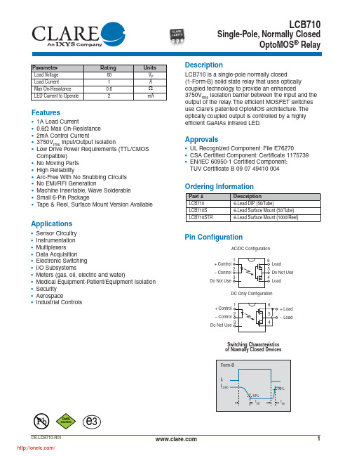
Applications
• Sensor Circuitry • Instrumentation • Multiplexers • Data Acquisition • Electronic Switching • I/O Subsystems • Meters (gas, oil, electric and water) • Medical Equipment-Patient/Equipment Isolation • Security • Aerospace • Industrial Controls
RoHS
2002/95/EC
DS-LCB710-R01
/
e3
Switching Characteristics of Normally Closed Devices
Form-B
IF ILOAD
10% toff
90% ton
1
Absolute Maximum Ratings @ 25ºC
Typical LED Forward Voltage Drop (N=50, TA=25ºC)
30
25
20
15
10
5
0 1.220 1.225 1.230 1.235 1.240 1.245 1.250 LED Forward Voltage (V)
Device Count (N)
PERFORMANCE DATA*
Ordering Information
Part # LCB710 LCB710S LCB710STR
Description 6-Lead DIP (50/Tube) 6-Lead Surface Mount (50/Tube) 6-Lead Surface Mount (1000/Reel)
WP710A10SRCE;中文规格书,Datasheet资料

Electrical / Optical Characteristics at TA=25°C
Symbol λpeak λD [1] Δλ1/2 C VF [2] IR Parameter Peak Wavelength Dominant Wavelength Spectral Line Half-width Capacitance Forward Voltage Reverse Current Device Super Bright Red Super Bright Red Super Bright Red Super Bright Red Super Bright Red Super Bright Red Typ. 660 640 20 45 1.85 2.5 10 Max. Units nm nm nm pF V uA Test Conditions IF=20mA IF=20mA IF=20mA VF=0V;f=1MHz IF=20mA VR = 5V
Super Bright Red
WP710A10SRC/E
SPEC NO: DSAL0548 APPROVED: WYNEC
REV NO: V.2 CHECKED: Allen Liu
DATE: MAR/07/2011 DRAWN: J.Yu
PAGE: 3 OF 6 ERP: 1101029119
T-1 (3mm) SOLID STATE LAMP
Part Number: WP710A10SRC/E Super Bright Red
Hale Waihona Puke Featuresz Low power consumption. z Popular T-1 diameter package. z General purpose leads. z Reliable and rugged. z Long life - solid state reliability. z Available on tape and reel. z RoHS compliant.
2N7000中文资料(fairchild)中文数据手册「EasyDatasheet - 矽搜」
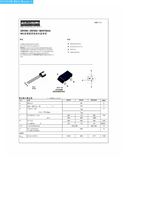
Typ e
Min
Typ
Max
Units
持续 通态漏电流
I
V V V V V V
= 4.5 V, V = 10 V, V = 10 V, V = 10 V, I 2V 2V
= 10 V 2V 2V =200毫安 , I =200毫安 , I =200毫安 = 0 V,
2N7000 2N7002 NDS7002A 2N7000 2N7002 NDS7002A
I I V
最大连续漏源极正向电流
2N7002 NDS7002A 2N7002 NDS7002A
115 280 0.8 1.5 0.88 0.88 1.5 1.2
mA A V
最大脉冲漏源极正向电流
漏源二极管正向 电压
V V
= 0 V, I = 0 V, I
=115毫安 =400毫安
2N7002 NDS7002 A
90%
tf
RL V出
DUT
输入,输入电压
50%
输出时,VOUT
VGS
10%
10% 90% 50%
R GEN
倒
G
S
10%
脉宽
图 11.
图 12.开关波形
所有
Hale Waihona Puke 60 1 1 1 0.5 10 100 -10 -100
V µA mA µA mA nA nA nA nA
2N7000 2N7002 NDS7002A 2N7000 2N7002 NDS7002A 2N7000 2N7002 NDS7002A 2N7000 2N7002 NDS7002A 2N7000
I
门 - 体泄漏,前进
V V
M710e 用户指南和硬件维护手册说明书

第 3 章 计算机锁. . . . . . . . . . . . 9
锁住计算机外盖 . . . . . . . . . . . . . . 9 连接 Kensington 式钢缆锁 . . . . . . . . 10 连接钢缆锁 . . . . . . . . . . . . . . . 11
图 7. 连接钢缆锁
第 3 章 . 计 算 机 锁 11
12 M710e 用户指南和硬件维护手册
第 4 章 更换硬件
本章提供如何为您的计算机更换硬件的说明。
更换硬件之前
注意:打开计算机或尝试进行任何修理之前,请先阅读本节和《重要产品信息指南》。
更换硬件之前需要注意的事项 • 仅使用 Lenovo 提供的计算机组件。 • 安装或更换选件时,请使用本手册中列出的相应说明以及随选件附带的说明。 • 在全世界大部分地区,Lenovo 都要求退回有问题的 CRU。CRU 附带有关此事宜的信息,或将
2 M710e 用户指南和硬件维护手册
后视图
注:您的计算机型号可能与插图略有不同。
图 2. 后视图
1 音频输出接口 3 VGA 输出接口 5 USB 3.1 Gen 1 接口(2) 7 串口 9 线缆锁插槽 (2) 11 安全锁插槽 13 PCI-Express 卡区域
2 DisplayPort® 输出接口 4 USB 2.0 接口(2) 6 电源线接口 8 以太网接口 10 挂锁环 12 串口(选配)
图 1. 前视图
1 光盘驱动器弹出/关闭按钮 3 内置扬声器(选配) 5 读卡器插槽(选配) 7 电源按钮
2 光盘驱动器状态指示灯 4 存储驱动器状态指示灯 6 电源指示灯 8 麦克风接口
10A10

10A10
10A10在R-6封装里采用的1个芯片,是一款轴向大电流整流二极管。
10A10的浪涌电流Ifsm为600A,漏电流(Ir)为
10uA,其工作时耐温度范围为-55~150摄氏度。
10A10采用GPP硅芯片材质,里面有1颗芯片组成。
10A10的电性参数是:正向电流(Io)为10A,反向耐压为1000V,正向电压(VF)为1.0V,其中有2条引线。
10A10参数描述
型号:10A10
封装:R-6
特性:轴向大电流整流二极管
电性参数:10A 1000V
芯片材质:GPP
正向电流(Io):10A
芯片个数:1
正向电压(VF):1.0V
浪涌电流Ifsm:600A
漏电流(Ir):10uA
工作温度:-55~+150℃
引线数量:2
10A10轴向大电流封装系列。
它的本体长度为9.1mm,加引脚长度为59.9mm,宽度为9.1mm,高度为9.1mm。
10A10拥有低正向压降、低反向漏电流、高正向浪涌电流能力等特点。
文石tab10参数

文石tab10参数一、产品概述文石tab10是一款10.3英寸的电子书平板电脑,专为阅读设计。
它采用高清显示屏,支持多种阅读格式,并配备了丰富的阅读辅助功能,如书签、批注、字体调整等,为用户提供沉浸式的阅读体验。
二、主要参数1. 尺寸与重量:尺寸:160mm x 243mm x 7.8mm重量:约485g2. 屏幕:尺寸:10.3英寸分辨率:2240x1660像素类型:IPS显示屏色彩:1677万色阅读格式支持:PDF,EPUB,TXT等3. 处理器:芯片:Rockchip RK3568八核处理器,主频1.8GHz4. 内存与存储:内存:3GB LPDDR4X双通道内存存储:64GB eMMC高速存储扩展存储:支持microSD卡扩展,最大支持512GB5. 电池:电池容量:6000mAh锂离子电池充电方式:USB-C充电接口(5V-3A)待机时间:约12小时(典型使用场景)6. 其他功能:操作系统:Frida Android系统,可刷各种定制版固件前置摄像头:2百万像素,支持视频通话和人脸识别功能后置摄像头:5百万像素,支持拍照和视频录制蓝牙版本:蓝牙5.0版本,支持蓝牙耳机、键盘等设备连接WiFi标准:Wi-Fi a/b/g/n/ac,支持2.4G和5G网络连接音频播放:支持MP3、WAV、FLAC等音频格式播放录音功能:支持录音功能,内置麦克风三、阅读功能文石tab10内置多种阅读格式支持,可轻松阅读PDF、EPUB、TXT等格式的书籍。
同时,它还具备以下阅读辅助功能:1. 书签功能:用户可以在阅读过程中方便地添加书签,标记重要部分。
2. 批注功能:用户可以在书籍中添加文字、图片等批注,方便后续回顾。
3. 字体与亮度调整:用户可以通过系统设置调整字体大小、颜色和亮度,以满足不同阅读需求。
4. 翻页效果:用户可以选择不同的翻页效果,增加阅读体验。
5. 夜间模式:系统内置夜间模式,适合在昏暗环境下阅读。
波士顿家用电器官方网站商品说明书

Accessories: To purchase Bosch accessories, cleaners & parts please visit /us/store or call 1-800-944-2904 (Mon to Fri 5 am to 6 pm PST, Sat 6 am to 3 pm PST).SHXM78Z54N Black Stainless Steel Also available in:Stainless Steel SHXM78Z55N White SHXM78Z52N BlackSHXM78Z56NPatented CrystalDry™ technology transforms moisture into heat to get dishes, including plastics, 60% drier.142 dBA: dishwasher runs quietly so your kitchen conversations aren’t interrupted.The Flexible 3rd Rack with fold down sides adds 30% more 2 loading area, perfect for utensils and ramekins.The AquaStop® leakprotection system contains leaks through a precisely engineered system. If a leak occurs, the system contains it by shutting down operation andpumping out water. So you have the ultimate peace of mind whether you are away or at home.1Based on aggregate average drying performance of Bosch Dishwashers with CrystalDry on combined household load including plastics, glass, steel, and porcelain as compared to Bosch Dishwashers with PureDry. Drying performance may vary by dish type.2Compared to a Bosch dishwasher with 2 racks.3Certification to NSF/ANSI Standard 184 for residential dishwashers. 4September 2020 running production change to remove adhesive routing clips for power cord. These clips and the edge protector are now included in the dishwasher accessory kit # SMZEPCC1UC.Accessories: To purchase Bosch accessories, cleaners & parts please visit /us/store or call 1-800-944-2904 (Mon to Fri 5 am to 6 pm PST, Sat 6 am to 3 pm PST).Installation DetailsJunction box accessoryInstallation DetailsAccessories: To purchase Bosch accessories, cleaners & parts please visit /us/store or call 1-800-944-2904 (Mon to Fri 5 am to 6 pm PST, Sat 6 am to 3 pm PST).。
TW10a 10寸2路全频有源专业扬声器系统 CN 产品说明书

TW10a10寸2路全频有源专业扬声器系统CN产品说明书UM-T W10a-20180423V e r B感谢您购买 产品!请仔细阅读本手册,它将帮助你妥善设置并运行您的系统,使其发挥卓越的性能。
并保留这些说明以供日后参照。
警告:为了降低火灾与电击的风险,请不要将产品暴露在雨中或潮湿环境中。
警告:为了降低电击的风险,非专业人士请勿擅自拆卸该系统。
仅供专业人士操作。
等边三角形中的闪电标记,用以警示用户该部件为非绝缘体,系统内部存在着电压危险,电压。
可能足以引起触电。
可能足以引起触电如系统标有带惊叹号的等边三角形,则是为提示用户严格遵守本用户指南中的操作与维护规定。
注意:请勿对系统或附件作擅自的改装。
未经授权擅自改装将造成安全隐患。
警告:燃不得将明火源(如点的蜡烛)放在器材上面。
1. 请先阅读本说明。
2. 保留这些说明以供日后参照。
3. 注意所有警告信息。
4. 遵守各项操作指示。
5. 不要在雨水中或潮湿环境中使用本产品。
6. 不要将产品靠近热源安装,例如暖气管、加热器、火炉或其它能产生热量的装置(包括功放机 )。
7. 不要破坏极性或接地插头的安全性设置。
如果提供的插头不能插入插座,则应当请专业人员更换插座。
8. 保护好电源线和信号线,不要在上面踩踏或拧在一起(尤其是插头插座及穿出机体以外的部分 )。
9. 使用厂商规定及符合当地安全标准的附件。
10.雷电或长时间不使用时请断电以防止损坏产品。
12. 不要让物体或液体落入产品内——它们可能引起火灾或触电。
13. 请注意产品外罩上的相关安全标志。
. 仅与厂商指定或与电器一同售出的推车、架子、三脚架、支架或桌子一起使用。
推动小车电/器时,应谨防翻倒。
11注意事项产品的安装调试须由专业人士操作。
在使用非本厂规定的吊装件时,要保证结构的强度并符合当地的安全规范。
警告:1扬声器及扬声器系统的产品有限保修期为自正式购买日起的3年。
由于用户不合理的应用而导致音圈烧毁或纸盆损坏等故障,不包含于产品保修项目。
CWSB11AA2F;CWSB21AA1F;CWSB21AA2F;CWSA11AANS;CWSA11AAN1S;中文规格书,Datasheet资料
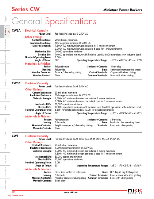
Series CWMiniature Power RockersB12I n d i c a t o r sA c c e s s o r i e sS u p p l e m e n tT a c t i l e sK e y l o c k sR o t a r i e sP u s h b u t t o n sI l l u m i n a t e d P BS l i d e s P r o g r a m m a b l eT o u c hT i l tT o g g l e sGeneral SpecificationsElectrical CapacityPower Level: For Resistive Load 6A @ 250V ACOther RatingsContact Resistance: 20 milliohms maximumInsulation Resistance: 500 megohms minimum @ 500V DCDielectric Strength: 1,500V AC minimum between contacts for 1 minute minimum3,000V AC minimum between contacts & case for 1 minute minimum Mechanical Life: 30,000 operations minimumElectrical Life: 10,000 operations minimum with Resistive Load & 6,000 operations with Inductive Load N ominal Operating Force: 2.50N Angle of Throw: 30° Operating Temperature Range: –10°C ~ +70°C (+14°F ~ +158°F)Materials & FinishesRocker: Polycarbonate Stationary Contacts:Silver alloyHousing:PolyamideBase:Laminated thermosetting sheets Movable Contactor: Brass w/silver alloy plating Contact Terminals: Copper with silver platingMovable Contacts:SilverCommon Terminals:Brass with silver platingElectrical CapacityPower Level: For Resistive Load 6A @ 250V ACOther RatingsContact Resistance:20 milliohms maximumInsulation Resistance: 500 megohms minimum @ 500V DCDielectric Strength: 1,500V AC minimum between contacts for 1 minute minimum3,000V AC minimum between contacts & case for 1 minute minimum Mechanical Life: 30,000 operations minimumElectrical Life: 10,000 operations minimum with Resistive Load & 6,000 operations with Inductive Load N ominal Operating Force: 6.50N for single pole models; 10.0N for double pole models Angle of Throw: 30° Operating Temperature Range: –10°C ~ +70°C (+14°F ~ +158°F)Materials & FinishesRocker: Polycarbonate Stationary Contacts: Silver alloy Housing:Polyamide Base: Laminated thermosetting sheets Movable Contactor: Beryllium copper w/silver alloy plating Terminals: Brass with silver platingMovable Contacts:SilverElectrical CapacityPower Level: For Resistive Load 6A @ 125V AC; 3A @ 250V AC; 4A @ 30V DCOther RatingsContact Resistance:20 milliohms maximumInsulation Resistance: 1,000 megohms minimum @ 500V DCDielectric Strength: 1,000V AC minimum between contacts for 1 minute minimum1,500V AC minimum between contacts & case for 1 minute minimum Mechanical Life: 50,000 operations minimum Electrical Life: 25,000 operations minimum N ominal Operating Force: 2.0N Angle of Throw:30° Operating Temperature Range: –25°C ~ +70°C (–13°F ~ +158°F)Materials & FinishesRocker: Glass fiber reinforced polyamide Base: LCP (Liquid Crystal Polymer) Housing:Polyamide Contact Terminals: Brass + silver with silver plating Movable Contactor: Phosphor bronze w/silver plating Common Terminals: Brass with silver platingMovable Contacts:Silver alloyCWSB CWT CWSA/Series CWMiniature Power Rockers B13I n d i c a t o r s A c c e s s o r i e s S u p p l e m e n t T a c t i l e s K e y l o c k s R o t a r i e s P u s h b u t t o n s I l l u m i n a t e d P B S l i d e s P r o g r a m m a b l e T o g g l esT o u c h T i lt Distinctive CharacteristicsCWSALow cost molded rocker.See-saw contact mechanismStable stationary contact construction for high reliability.Easily installed with snap-in mounting.Large terminal hole dimensioned .067” x .098” (1.7mm x 2.5mm) simplifies wiring and soldering.Wave Soldering (PC version): See Profile A in Supplement section. Manual Soldering: See Profile A in Supplement section.CWSBLow cost molded rocker.Snap-acting contact mechanism gives smooth actuation and audible feedback.Stable stationary contact construction for high reliability.Front panel, snap-in mounting for labor-saving installation.Solder lug/quick connect terminals can be used with connectors.Manual Soldering: See Profile B in Supplement section.CWTLow cost molded rocker in compact, slim design.See-saw contact mechanismOutstanding insulation resistance and dielectric strength.Dust proof construction protects contact area.Stable stationary contact construction for high reliability.Front panel, snap-in mounting for labor-saving installation.Terminals are molded in and epoxy sealed to lock out flux, dust, and other contaminants.Manual Soldering: See Profile A in Supplement section./Series CWMiniature Power RockersB14I n d i c a t o r sA c c e s s o r i e s S u p p l e m e n tT a c t i l e sK e y l o c k sR o t a r i e sP u s h b u t t o n sI l l u m i n a t e d P B S l i d e sP r o g r a m m a b l eT o u c h T i l t T o g g l e sSTANDARDS & CERTIFICATIONSCWSASpecific CWSA models listed below are qualified for Underwriters Laboratories Inc. recognition and Canadian Standards Association certification. cULus marking on case is standard as noted in following table.Model Ratings @ AC cULus File No. Marking on CaseCWSA11 6A @ 250V E44145 StandardCWSA126A @ 250VE44145StandardCWSBSpecific CWSB models listed below are qualified for Underwriters Laboratories Inc. recognition and Canadian Standards Association certification. cULus marking on case is standard as noted in following table.Model Ratings @ AC cULus File No. Marking on CaseCWSB11 6A @ 250V E44145 StandardCWSB216A @ 250VE44145StandardCWTSpecific CWT model listed below is qualified for Underwriters Laboratories Inc. recognition and Canadian Standards Association certification. cULus marking on case is standard as noted in following table.Model Ratings @ AC cULus File No. Marking on CaseCWT126A @ 125V E44145Standard3A @ 250V/Series CWMiniature Power RockersB15I n d i c a t o r sA c c e s s o r i e s S u p p l e m e n t T a c t i l e s K e y l o c k s R o t a r i e s P u s h b u t t o n s I l l u m i n a t e d P BS l i d e s P r o g r a m m a b l e T o g g l esT o u c hT i ltTYPICAL ORDERING EXAMPLECWSA11AANSTYPICAL SWITCH ORDERING EXAMPLESFor SPST & SPDTNo CodeNoneFor SPST 1Horizontal 2Vertical 3Dot MarkingTYPICAL ORDERING EXAMPLECWSB21AA2FCWT12AAS1* Wire harness & cable assemblies offered only in Americas* Wire harness & cable assemblies offered only in Americas* Wire harness & cable assemblies offered only in Americas/Series CWMiniature Power RockersB16I n d i c a t o r s A c c e s s o r i e sS u p p l e m e n tT a c t i l e sK e y l o c k sR o t a r i e s P u s h b u t t o n sI l l u m i n a t e d P B S l i d e sP r o g r a m m a b l eT o u c hT i l t T o g g l e sTYPICAL SWITCH DIMENSIONS FOR CWSACWSA12AANSRight Angle Single Pole • Horizontal On-Off InscriptionSolder LugSingle Pole • No InscriptionCWSA11AAN1HINSCRIPTIONSNoneNot available in double pole.No CodeHorizontal OrientationOnly On-None-Off models are available with the horizontal inscription.1Vertical OrientationOnly On-None-Off models are available with the vertical inscription.2Dot MarkingOnly Single Pole On-None-Off models are available with the dot inscription.3The IEC symbols for On-Off are supplied with Single Throw models only. Orientation of inscription must be selected.Inscription color is white ink on black.Panel Thickness .030” ~ .079” (0.75mm ~ 2.0mm)Terminal numbers are on side of switch body Terminal numbers areon side of switch bodySingle throw model doesnot have terminal 1b /Series CWMiniature Power RockersB17I n d i c a t o r s A c c e s s o r i e s S u p p l e m e n tT a c t i l e sK e y l o c k sR o t a r i e sP u s h b u t t o n sI l l u m i n a t e d P B S l i d e sP r o g r a m m a b l e T o g g l esT o u c hT i l tCWT12AAS1Single Pole • No InscriptionSolder LugTYPICAL SWITCH DIMENSIONS FOR CWSBCWSB21AA2FSingle Pole • Dot Inscription Right AngleDouble Pole • Vertical On-Off InscriptionQuick ConnectCWSB11AA3HFootprint DPSTPanel Thickness .030” ~ .079” (0.75mm ~ 2.0mm)TYPICAL SWITCH DIMENSIONS FOR CWTPanel Thickness .030” ~ .079” (0.75mm ~ 2.0mm)FootprintSPSTTerminal numbers are on bottom of switchTerminal numbers are on bottom of switchTerminal numbers are on side of switch body /分销商库存信息:NKK-SWITCHCWSB11AA2F CWSB21AA1F CWSB21AA2F CWSA11AANS CWSA11AAN1S CWSA11AAN2S CWSA11AAN3S CWSB11AAF CWSA12AANS CWT12AAS1CWSA11AAN1H CWSB11AA1F CWSB11AA3F CWT12AAS1/U CWSA12AANH CWSA11AANH CWSB11AAH CWSA11AAN2H CWSB11AA1H CWT12AAS1/UC CWSB11AA3H CWSB21AA1H CWSB21AA2H。
FQT7N10L中文资料

Figure 1. On-Region Characteristics
1.5
1.2 V = 5V
GS
0.9 V = 10V
GS
0.6
0.3
※ Note : T = 25℃ J
0.0 0
5
10
15
20
ID, Drain Current [A]
Figure 3. On-Resistance Variation vs. Drain Current and Gate Voltage
Electrical Characteristics
Symbol
Parameter
TC = 25°C unless otherwise noted
Test Conditions
Min Typ Max Units
Off Characteristics
BVDSS ∆BVDSS / ∆TJ
Drain-Source Breakdown Voltage
TJ, TSTG
TL
Parameter
Drain-Source Voltage
Drain Current
- Continuous (TC = 25°C) - Continuous (TC = 70°C)
Drain Current - Pulsed
(Note 1)
Gate-Source Voltage
VGS Top : 10.0 V
8.0 V 6.0 V 5.0 V 4.5 V 4.0 V 3.5 V Bottom : 3.0 V
100
10-1 10-1
※ Notes :
1. 250μ s Pulse Test 2. TC = 25℃
波农高性能功率测量仪型号参数规格书说明书

Net RF Power absorbed by sensor
Thermocouples Diode Detectors
Power Meter
Power sensor
Substituted DC or low frequency
equivalent
Fig 1: Typical block diagram for direct power measurement. The RF source can be any RF signal attached to the power sensor. Three different types of sensors are available based on
Calibration and Traceability Boonton employs both a linearity calibration as well as a frequency response calibration. This maximizes the performance of Diode Sensors and corrects non-linearity on all ranges. Linearity calibration can be used to extend the operating range of a Diode Sensor. It can also be used to correct non-linearity throughout a Thermocouple or Diode sensor’s dynamic range. Frequency calibration factors (NIST traceable) and other data are stored within all peak power sensors. Linearity calibration is performed using the peak power meter’s built-in calibrator.
72-7710-Tenma.pdf - 数字万用表 - Tenma.pdf-说明书

TOLERANCES:
UNLESS OTHERWISE SPECIFIED, DIMENSIONS ARE FOR REFERENCE PURPOSES ONLY.
DRAWN BY: Veena CHECKED BY: Suresh
APPROVED BY: Farnell
DATE: 05/05/09
PART NO.
72-7710
ECN # REV
-
A
REVISIONS
DESCRIPTION RELEASED
DRAWN DATE CHECKD DATE APPRVD DATE Ramya 05/05/09 Suresh 05/05/09 Farnell 19/05/09
This data sheet and its contents (the "Information") belong to the Premier Farnell Group (the "Group") or are licensed to it. No licence is granted for the use of it other than for information purposes in connection with the products to which it relates. No licence of any intellectual property rights is granted. The Information is subject to change without notice and replaces all data sheets previously supplied. The Information supplied is believed to be accurate but the Group assumes no responsibility for its accuracy or completeness, any error in or omission from it or for any use made of it. Users of this data sheet should check for themselves the Information and the suitability of the products for their purpose and not make any assumptions based on information included or omitted. Liability for loss or damage resulting from any reliance on the Information or use of it (including liability resulting from negligence or where the Group was aware of the possibility of such loss or damage arising) is excluded. This will not operate to limit or restrict the Group's liability for death or personal injury resulting from its negligence. TENMA is the registered trademark of the Group. © Premier Farnell plc 2009.
波士顿专家级顶装洗衣机 WOE751D0IN WMZ2380 产品说明书

Series 2, washing machine, top loader, 680 rpmWOE751D0INWMZ2380 Extension for cold water inlet /Aquastop Treat your clothes with hand-like wash with Bosch Expertcare range of Top Load Washing machines• Stain Removal - Effectively removes most common* stains for spotlessly clean laundry• Reload function: forgot an item? Add it easily to the wash.• PowerWave Wash System is a combination of the innovatively designed pulsator, dynamic waterflow system and intelligent drum movement which gives perfect wash results• Delay Start gives the option of scheduling the wash cycle anytime within 24 hrs• Easy Start: easy start by only touching one button. The machine automatically detects how much laundry is loaded and choses the right program.Built-in / Free-standing: ..................................................Freestanding Door hinge: .................................................................................other Height of the appliance: .......................................................1015 mm Dimensions of the product: ...............................1015 x 542 x 600 mm Wheels: ...........................................................................................No Net weight: ..............................................................................40.2 kg Color Buttons: ..........................................black, start button in silver Noise level washing: ................................................65 dB(A) re 1 pW Fuse protection: ...........................................................................10 A Voltage: ...............................................................................220-240 V Frequency: .................................................................................50 Hz Energy Star Qualified: .....................................................................No Cord Included: ...............................................................................Yes Plug type: .........................................................India plug (6 Ampere) Dimensions of the packed product: ..................40.94 x 24.80 x 24.21 Net weight: .........................................................................89.000 lbs Gross weight: .....................................................................95.000 lbs Dimensions of the packed product (HxWxD): ...1040 x 615 x 630 mm Gross weight: ..........................................................................43.0 kg Fuse protection: ...........................................................................10 A Voltage: ...............................................................................220-240 V Frequency: .................................................................................50 Hz Water protection system: ............................Multiple water protection Max. spin speed: ....................................................................680 rpm Digital countdown indicator: .........................................................Yes Drying progress indicator: ................................................LED-display Maximum capacity in kg (EU 2017/1369): .................................7.5 kgSeries 2, washing machine, toploader, 680 rpmWOE751D0INTreat your clothes with hand-like wash with Bosch Expertcare range of Top Load Washing machinesTechnical InformationProgrammesFeaturesSafetyDisplay Screen & Alerts- Capacity: 7.5kg- Maximum spin speed: 480 rpm- Dimensions (HxWxD): 1050x640x650- Smart Suggest, Quick Wash, Mix, Delicates, Bedsheet, Whites, Cotton 30º, Tub Clean- 1.ExpertCare wash system inspired by hand wash:- a. Vario Drum: Specially designed Droplet Patterned drum which gently rubs the clothes during the wash mimicking the soft rubbing by hands like in a hand wash- b. Asymmetric Paddle design: The design which is rough on one side and smooth on the other side inspired by the 'Rough surfaces used during hand wash'- c. Scrub Pads: These are located at the bottom of the drum which gently scrubs your clothes for a superior wash perfomance like a scrubbing with brush during hand wash- d. Pumping tower & Magic filter: The pumping tower circulates water up and down and intermittently splashes fresh water for better mixing of detergent during the wash. The detachable and cleanable magic filter collects all the lint from clothes during the wash- e. Pulsator: Innovatively designed pulsator to ensure maximum water displacement for better wash quality- 2. Ergonomic Panel Design: User friendly back panel interface for smooth operations.- 3. Flexible Soaking: Pre soak your clothes with 4 flexible timer options like (15,30,45,60 mins) in the washing machine itself and reduce your efforts by avoiding it by doing in a bucket and transfering later into the washing machine.- 4. Anti Tangle: A program to reduce the problem of clothes tangling during wash- 5. EcoSilence Drive: A smooth and slient induction motor for maximum power and best washing results with 10 year warranty- 6. Soft Closing Lid provides a gradual lid closure to ensure an injury-free and silent closing of the washer lid- 7. Favorite: Chose your favorite / frequently used program saved in the favorite program option. Click and wash !!- 8. Delay Start upto 24 hours to delay the time at when the program starts- 9. Mobility Solution: The ergonomic handles at the back with wheels at the bottom to move your machine with ease as per your convinience and requirement- 10. Flexible Detergent Drawer: A convinient detergent drawer with separate compartments for powder detergent, liquid detergent and fabric softener- 11. Level indicator: Indicates the even placement of the machine soyou can avoid shaking at high RPM spinning- Volt Check: shows Voltage error when Voltage goes out of working range(mentioned in User manual, 170V to 280V) and machine stops running.- Child-proof lock- User Interface Type 1 with wash type, soak option, favourite, Water level selector and Rinse- Buzzer alert at the end of the wash programmeSeries 2, washing machine, top loader, 680 rpmWOE751D0IN。
WP7A 母座
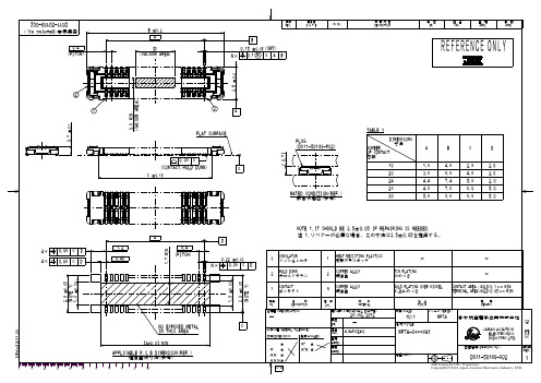
年月日 D A T E
CN NO.
変 更 内 容 DESCRIPTION
製 図 DR.
担 当 CHK.
査 閲 APPD.
承 認 APPD.
2
(VACUUM AREA)
1
0.7 ±0.1 0.6 MIN
3
2.5 ±0.2
0.08 C ±0.15
S S
0.7
4× 4×
0.06 0.06
C C
D D
1.7 MIN
2.9 ±0.05
1.8 ±0.03
1.9 ±0.03
(NOTE 1)
2.9 ±0.05
(NOTE 1)
DCF-C-212G(11.08)
H.MATSUZAKI
寸法(DIMENSION)
角度(ANGLES)
WP7A-S***VA1
【A+0.8】MIN
D
(PITCH)
0.22 ±0.03 0.06 C N× D
3
INSULATOR インシュレータ HOLD DOWN ホールドダウン CONTACT コンタクト
名 称 DESCRIPTION
1
HEAT RESISTING PLASTICS 耐熱プラスチック COPPER ALLOY 銅合金 COPPER ALLOY 銅合金
. . . .
± ± ± ±
APPLICABLE P.C.B DIMENSION(REF.) 適合基板寸法(参考)
10 20 30 40 50 60 70 80 90 100
°± ’± °
図面番号(DRAWING NO.)
質量(MASS)
版数 (REV.)
DS11-50189-S02
- 1、下载文档前请自行甄别文档内容的完整性,平台不提供额外的编辑、内容补充、找答案等附加服务。
- 2、"仅部分预览"的文档,不可在线预览部分如存在完整性等问题,可反馈申请退款(可完整预览的文档不适用该条件!)。
- 3、如文档侵犯您的权益,请联系客服反馈,我们会尽快为您处理(人工客服工作时间:9:00-18:30)。
Notes: 1. θ1/2 is the angle from optical centerline where the luminous intensity is 1/2 of the optical peak value. 2. Luminous intensity/ luminous Flux: +/-15%.
PACKING & LABEL SPECIFICATIONS
WP710A10NT
SPEC NO: DSAL0516 APPROVED: WYNEC
REV NO: V.2 CHECKED: Allen Liu
DATE: MAR/07/2011 DRAWN: J.Yu
PAGE: 4 OF 6 ERP: 1101029070
Notes: 1. 1/10 Duty Cycle, 0.1ms Pulse Width. 2. 2mm below package base. 3. 5mm below package base.
Pure Orange 62.5 25 145 5 -40°C To +85°C 260°C For 3 Seconds 260°C For 5 Seconds
/
SPEC NO: DSAL0516 APPROVED: WYNEC
REV NO: V.2 CHECKED: Allen Liu
DATE: MAR/07/2011 DRAWN: J.Yu
PAGE: 5 OF 6 ERP: 1101029070
/
Description
The Pure Orange source color devices are made with Gallium Arsenide Phosphide on Gallium Phosphide Pure Orange Light Emitting Diode.
Package Dimensions
Units mW mA mA V
SPEC NO: DSAL0516 APPROVED: WYNEC
REV NO: V.2 CHECKED: Allen Liu
DATE: MAR/07/2011 DRAWN: J.Yu
PAGE: 2 OF 6 ERP: 1101029070
/
Pure Orange
WP710A10NT
SPEC NO: DSAL0516 APPROVED: WYNEC
REV NO: V.2 CHECKED: Allen Liu
DATE: MAR/07/2011 DRAWN: J.Yu
PAGE: 3 OF 6 ERP: 1101029070
/
SPEC NO: DSAL0516 APPROVED: WYNEC
REV NO: V.2 CHECKED: Allen Liu
DATE: MAR/07/2011 DRAWN: J.Yu
PAGE: 1 OF 6 ERP: 1101029070
/
Selection racteristics at TA=25°C
Symbol λpeak λD [1] Δλ1/2 C VF [2] IR Parameter Peak Wavelength Dominant Wavelength Spectral Line Half-width Capacitance Forward Voltage Reverse Current Device Pure Orange Pure Orange Pure Orange Pure Orange Pure Orange Pure Orange Typ. 607 610 35 15 2.05 2.5 10 Max. Units nm nm nm pF V uA Test Conditions IF=20mA IF=20mA IF=20mA VF=0V;f=1MHz IF=20mA VR = 5V
T-1 (3mm) SOLID STATE LAMP
Part Number: WP710A10NT Pure Orange
Features
z Low power consumption. z Popular T-1 diameter package. z General purpose leads. z Reliable and rugged. z Long life - solid state reliability. z Available on tape and reel. z RoHS compliant.
SPEC NO: DSAL0516 APPROVED: WYNEC
REV NO: V.2 CHECKED: Allen Liu
DATE: MAR/07/2011 DRAWN: J.Yu
PAGE: 6 OF 6 ERP: 1101029070
/
分销商库存信息:
KINGBRIGHT WP710A10NT
Notes: 1.Wavelength: +/-1nm. 2. Forward Voltage: +/-0.1V.
Absolute Maximum Ratings at TA=25°C
Parameter Power dissipation DC Forward Current Peak Forward Current [1] Reverse Voltage Operating/Storage Temperature Lead Solder Temperature [2] Lead Solder Temperature [3]
Notes: 1. All dimensions are in millimeters (inches). 2. Tolerance is ±0.25(0.01") unless otherwise noted. 3. Lead spacing is measured where the leads emerge from the package. 4. The specifications, characteristics and technical data described in the datasheet are subject to change without prior notice.
