罗克韦尔软件安装OPL
AB MICROLOGIX opc配置说明
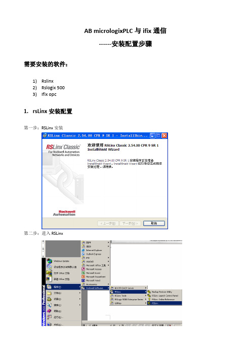
AB micrologixPLC与ifix通信------安装配置步骤需要安装的软件:1)Rslinx2)Rslogix 5003)Ifix opc1.rsLinx安装配置第一步:RSLinx安装第二步:进入RSLinx第三步:配置IP地址1.配置驱动2.选择Ethernet devices3. 4.把PLC的IP增加到网络中5.通过以太网模块读到CPU第四步:验证RSLINX是否正常打开rslinx,找到相应PLC ip找到在RSLogix500中查看的变量,看看在RSLinx中是否变量显示正常关闭DataMonitor,再右击PLC,选择Configure New DDE/OPC Topic在新弹出的界面可更改Topic名称,点击OK点击Yes更新Topic下面可以通过RSLinx自带的OPC Client工具检测RSLinx OPC服务器是否正常读取PLC的数值通过开设菜单找到OPC Test Client选择新建OPC选择RSLinx OPC Server服务器,点击OK新建一个Group,点击OK可以在左下方找到刚才新建的Topic,随意添加一个PLC变量点击OK,然后可以看到可以正常监控到这个PLC变量值,此时说明RSLinx的OPC功能正常使用。
之后可以通过第三方上位机监控软件通过RSLinx OPC Server来监控PLC中的变量值。
2.rsLogix500安装配置第一步:rsLogix500安装输入专业版序列号授权:拷贝到U盘,然后点击执行,然后移到C盘进入rslogix 500:点击通讯,配置,如下图,选择Rslinx中配置好的PLC。
新建工程,选择1400系列PLC3.OPC安装配置以太网接口读写PLC,需要安装ifix opc驱动。
第一步,安装OPC驱动第二步:OPC建立项目OPC进入OPC后新建一个SEREVER.并点击ENABLE.选择Rslinx OPC Server新建一个group并点击ENABLE.新建一个item(名字可以改为你希望的标签名)并点击Browse Server.点击BROWSE SERVER从在线CPU中选取所要得I/O地址.如果在ENABLE IFIX PDB TAG AUTO 前点对勾,此点将以ITEM1的名称进入数据库.重新起名后点击ABC 加入数据库.之后在PDB中建点即可。
罗克韦尔自动化 FLEX I O 远程 I O 适配器模块 安装说明说明书
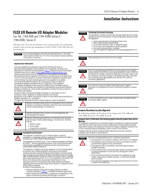
FLEX I/O Remote I/O Adapter Modules 1Publication 1794-IN098E-EN-P - January 2011Installation InstructionsFLEX I/O Remote I/O Adapter ModulesCat. No. 1794-ASB and 1794-ASBK Series E; 1794-ASB2, Series D(Modules with a K in the last position of the catalog number are conformally coated to meet noxious gas requirements of ISA/ANSI-71.040 1985 Class G3 Environment.)European Hazardous Location ApprovalThe following modules are European Zone 2 approved: 1794-ASB and 1794-ASBK Series E; 1794-ASB2, Series DDo not use these adapters (1794-ASB and 1794-ASBK Series E; 1794-ASB2, Series D) with the Classic PLC-5/15 or PLC-5/25 processors. Improper operation of the remote I/O can result.Important User InformationSolid state equipment has operational characteristics differing from those ofelectromechanical equipment. Safety Guidelines for the Application, Installation andMaintenance of Solid State Controls (Publication SGI-1.1 available from your local Rockwell Automation sales office or online at ) describes some important differences between solid state equipment and hard-wiredelectromechanical devices. Because of this difference, and also because of the wide variety of uses for solid state equipment, all persons responsible for applying this equipment must satisfy themselves that each intended application of this equipment is acceptable. In no event will Rockwell Automation, Inc. be responsible or liable for indirect or consequential damages resulting from the use or application of this equipment.The examples and diagrams in this manual are included solely for illustrative purposes. Because of the many variables and requirements associated with any particular installation, Rockwell Automation, Inc. cannot assume responsibility or liability for actual use based on the examples and diagrams.No patent liability is assumed by Rockwell Automation, Inc. with respect to use of information, circuits, equipment, or software described in this manual.Reproduction of the contents of this manual, in whole or in part, without written permission of Rockwell Automation, Inc., is prohibited.Throughout this manual we use notes to make you aware of safety considerations.Identifies information about practices or circumstances that can cause an explosion in a hazardous environment, which may lead to personal injury or death, property damage, or economic loss.Identifies information that is critical for successful application and understanding of the product.Identifies information about practices or circumstances that can lead to personal injury or death, property damage, or economic loss. Attentions help you:•identify a hazard •avoid a hazard•recognize the consequenceEnvironment and EnclosureThis equipment is intended for use in a Pollution Degree 2 industrialenvironment, in overvoltage Category II applications (as defined in IEC 60664-1), at altitudes up to 2000 m (6562 ft) without derating.This equipment is considered Group 1, Class A industrial equipment according to IEC/CISPR 11. Without appropriate precautions, there may be difficulties with electromagnetic compatibility in residential and other environments due to conducted and radiated disturbances.This equipment is supplied as open-type equipment. It must be mounted within an enclosure that is suitably designed for those specific environmentalconditions that will be present and appropriately designed to prevent personal injury resulting from accessibility to live parts. The enclosure must have suitable flame-retardant properties to prevent or minimize the spread of flame, complying with a flame spread rating of 5VA, V2, V1, V0 (or equivalent) if non-metallic. The interior of the enclosure must be accessible only by the use of a tool.Subsequent sections of this publication may contain additional information regarding specific enclosure type ratings that are required to comply with certain product safety certifications. In addition to this publication, see:•Industrial Automation Wiring and Grounding Guidelines, RockwellAutomation publication 1770-4.1, or additional installation requirements.•NEMA Standard 250 and IEC 60529, as applicable, for explanations of the degrees of protection provided by different types of enclosure.Preventing Electrostatic DischargeThis equipment is sensitive to electrostatic discharge, which can cause internal damage and affect normal operation. Follow these guidelines when you handle this equipment:•Touch a grounded object to discharge potential static.•Wear an approved grounding wriststrap.•Do not touch connectors or pins on component boards.•Do not touch circuit components inside the equipment.•Use a static-safe workstation, if available.•Store the equipment in appropriate static-safe packaging when not in use.Power wiring must be less than 10 m (33 ft) in length.FLEX I/O is grounded through the DIN rail to chassis ground. Use zinc plated yellow-chromate steel DIN rail to assure proper grounding. The use of other DIN rail materials (for example, aluminum or plastic) that can corrode, oxidize, or are poor conductors, can result in improper or intermittent grounding. Secure DIN rail to mounting surface approximately every 200 mm (7.8 in.) and use end-anchors appropriately.Do not remove or replace an adapter module while power is applied.Interruption of the backplane can result in unintentional operation or machine motion.To reduce susceptibility to noise, power analog modules and digital modules from separate power supplies.European Zone 2 Certification (The following applies when the product bears the Ex Marking)This equipment is intended for use in potentially explosive atmospheres as defined by European Union Directive 94/9/EC and has been found to comply with the Essential Health and Safety Requirements relating to the design and construction of Category 3 equipment intended for use in Zone 2 potentially explosive atmospheres, given in Annex II to this Directive.Compliance with the Essential Health and Safety Requirements has been assured by compliance with EN 60079-15 and EN 60079-0.Observe the following additional Zone 2 certification requirements:•This equipment is not resistant to sunlight or other sources of UV radiation.•This equipment must be installed in an enclosure providing at least IP54 protection when applied in Zone 2 environments.•This equipment shall be used within its specified ratings defined by Rockwell Automation.•Provision shall be made to prevent the rated voltage from being exceeded by transient disturbances of more than 40% when applied in Zone 2 environments.•Secure any external connections that mate to this equipment by using screws, sliding latches, threaded connectors, or other means provided with this product.•Do not disconnect equipment unless power has been removed or the area is known to be nonhazardous.2 FLEX I/O Remote I/O Adapter Modules Publication 1794-IN098E-EN-P - January 2011North American Hazardous Location ApprovalThe following modules are North American Hazardous Location approved: 1794-ASB and 1794-ASBK Series E; 1794-ASB2, Series D.Remote I/O Adapter 1794-ASB/E, 1794-ASBK/E, 1794-ASB2/DThese adapters are shipped configured for standard addressing mode. InStandard Addressing Mode, the 1794-ASB(K) series E adapter can be used as a replacement for 1794-ASB series A and B remote I/O adapters, and the 1794-ASB2 series D can be used for a replacement for 1794-ASB2 series A 2-slot remote I/O adapters.Installing Your Adapter ModuleMount on a DIN rail before installing the Terminal Base Units1.Hook the lip on the rear of the adapter onto the top of the DIN rail,and rotate the adapter module onto the rail.2.Press the adapter module down onto the DIN rail until flush. Lockingtab C will snap into position and lock the adapter module to the DIN rail.3.If the adapter module does not lock in place, use a screwdriver orsimilar device to move the locking tab down while pressing theadapter module flush onto the DIN rail, and release the locking tab to lock the adapter module in place. If necessary, push up on the locking tab to lock.4.Connect the adapter wiring as shown under “Wiring” later in thisdocument.Mount or Replace the Adapter on an Existing System1.Remove the RIO plug-in connector from the front of the adapter.2.Disconnect any wiring jumpered to the adjacent terminal base.3.Open the module latching mechanism and remove the module fromthe base unit to which the adapter will be attached.4.Push the FlexBus connector toward the right side of the terminal baseto unplug the backplane connection. (When fully retracted, you will see a raised dot on the connector).5.Release the adapter locking tab and remove the adapter module.The following information applies when operating this equipment in hazardous locations:Informations sur l’utilisation de cet équipement en environnements dangereux:Products marked "CL I, DIV 2, GP A, B, C, D" are suitable for use in Class I Division 2 Groups A, B, C, D, Hazardous Locations and nonhazardous locations only. Each product is supplied with markings on the rating nameplate indicating thehazardous location temperature code. When combining products within a system, the most adverse temperature code (lowest "T" number) may be used to help determine the overall temperature code of the system. Combinations of equipment in your system are subject to investigation by the local Authority Having Jurisdiction at the time of installation.Les produits marqués "CL I, DIV 2, GP A, B, C, D" ne conviennent qu'à une utilisation enenvironnements de Classe I Division 2 Groupes A, B, C, D dangereux et non dangereux. Chaque produit est livré avec des marquages sur sa plaque d'identification qui indiquent le code de température pour les environnements dangereux. Lorsque plusieurs produits sont combinés dans un système, le code de température le plus défavorable (code detempérature le plus faible) peut être utilisé pour déterminer le code de température global du système. Les combinaisons d'équipements dans le système sont sujettes à inspection par les autorités locales qualifiées au moment de l'installation.EXPLOSION HAZARD•Do not disconnect equipment unless power has been removed or the area is known to be nonhazardous.•Do not disconnect connections to this equipment unless power has been removed or the area is known to be nonhazardous. Secure any external connections that mate to this equipment by using screws, sliding latches, threaded connectors, or other means provided with this product.•Substitution of components may impair suitability for Class I, Division 2.•IIf this product contains batteries, they must only be changed in an area known to be nonhazardous.RISQUE D’EXPLOSION•Couper le courant ou s'assurer que l'environnemen t est classé non dangereux avant de débrancher l'équipement.•Couper le courant ou s'assurer que l'environnement est classé non dangereux avant de débrancher les connecteurs. Fixer tous les connecteurs externes reliés à cet équipement à l'aide de vis, loquets coulissants, connecteurs filetés ou autres moyens fournis avec ce produit.•La substitution de composants peut rendre cet équipement inadapté à une utilisation en environnement de Classe I, Division 2.•S'assurer que l'environnement est classé non dangereux avant de changer les piles.Component Identification 1Remote I/O Adapter Module 6Remote I/O cable connector 2Indicators7+V DC connections 3Communication reset button (PRL)8-V common connections 4Access door to switches S1 and S29FlexBus connector5Switches S1 and S2 (behind door)If you insert or remove the module while backplane power is on, an electrical arc can occur. This could cause an explosion in hazardous location installations. Be sure that power is removed or the area is nonhazardous before proceeding.If you connect or disconnect the communications cable with power applied to this module or any device on the network, an electrical arc can occur. This could cause an explosion in hazardous location installations. Be sure that power is removed or the area is nonhazardous before proceeding.For Class I Division 2 applications, use only Class I Division 2 listed or recognized accessories and modules approved for used within the 1794 platform.During mounting of all devices, be sure that all debris (metal chips, wire strands, etc.) is kept from falling into the module. Debris that falls into themodule could cause damage on power up.FLEX I/O Remote I/O Adapter Modules 3Publication 1794-IN098E-EN-P - January 20116.Before installing the new adapter, notice the notch on the right rear ofthe adapter. This notch accepts the hook on the terminal base unit. The notch is open at the bottom. The hook and adjacent connection point keep the terminal base and the adapter tight together, reducing the possibility of a break in communication over the backplane.plete the adapter mounting as shown below.8.If the adapter module does not lock in place, use a screwdriver orsimilar device to move the locking tab down while pressing theadapter module flush onto the DIN rail, and release the locking tab to lock the adapter module in place. If necessary, push up on the locking tab to lock.9.Reinstall the module in the adjacent terminal base unit.Connect the Wiring1.Connect the remote I/O cable to the removable remote I/Oconnector.2.Connect +V DC power to the left side of the lower connector,terminal A .3.Connect -V common to the left side of the upper connector,terminal B .4.Connections C and D are used to pass +V DC power (D) and -Vcommon (C) to the next module in the series (if required).Set the Addressing Mode Switches1.Lift the hinged switch cover on the front of the adapter to expose theswitches.2.Set the switches as shown below.3.Cycle power to the adapter after setting the switches.Do not wire more than 2 conductors on any single terminal.ConnectTo terminal Blue Wire - RIO 1Shield Wire - RIO SH Clear Wire - RIO2If you connect or disconnect wiring while the field-side power is on, an electrical arc can occur. This could cause an explosion in hazardous location installations.Be sure that power is removed or the area is nonhazardous before proceeding.Push down and in at the same time to lock the adapter to the DIN rail.When the adapter is locked onto the DIN rail, gently push the FlexBus connector into the adapter to complete the backplaneIf this is the last adapter, you must terminate the remote I/O link here. Use a terminating resistor connected across terminals 1 and 2. Refer to your processor manual for information on the size of the resistor.WARNINGWhen you change switch settings while power is on, an electrical arc can occur. This could cause an explosion in hazardous location installations. Be sure that power is removed or the area is nonhazardous before proceeding.ATTENTIONSome switches on this adapter differ from the switches on previous versions. Make certain that you identify each switch before setting.8 and 16-point Mode Switch SettingsWhen using this addressing modeAndMode Switch 2 S1-1Mode Switch 1 S2-5Mode Switch 0 S2-8Standard (as shipped)8 and/or 16-point modulesSee note 1ON ON Compact8-point modules OFF ON OFF 16-point modules ONONOFFComplementary See complementary table below.Primary Chassis 8-point modules OFFOFF ON Complementary ChassisONOFF ON Complementary See complementary table below.Primary Chassis 16-point modules OFF OFF OFF Complementary ChassisON OFF OFF 1In Standard mode, this switch retains its function as switch position 1 of rack addressing. In standard mode, the module is functionally interchangeable with 1794-ASB series A or B adapters.2In compact mode, 32-point modules appear as 8 or 16-point modules.3When programming block transfers, address analog modules as module 0 if switch S1-1 is on; module 1 if switch S1-1 is off.32-point Mode Switch SettingsWhen using thisaddressing modeAndMode Switch 0 S2-8Mode Switch 1 S2-5Mode Switch 2 S1-1ModeSwitch 3 S2-3Mode Switch 4 S2-4Standard – 328, 16 and/or 32-point modulesONONSee note 1OFFOFFComplementary – 324 FLEX I/O Remote I/O Adapter ModulesPublication 1794-IN098E-EN-P - January 2011Primary Chassis 8, 16 and/or 32-point modulesOFF OFF OFF OFF OFF Complementary ChassisOFF OFF ON OFF OFF 1In Standard – 32 mode, any module in the chassis occupies 32 input points and 32 output points in the input/output data table.2In Complementary – 32 mode, any module in the chassis occupies 32 input points or 32 output points in the input/output data table. If using 8 or 16-point modules,unused points in the data table are zeroed out.First I/O Group 1) (see Important)I/O Rack Number S1-8S1-7I/O Group S1-6…S1-1ON ON 0 (1st)Refer to addressing modetables.OFF ON 2 (2nd)ON OFF 4 (3rd)OFF OFF 6 (4th)1) In 32-point mode, starting quarter must be 0 (S1-8 and S1-7 on).S2-8Mode Switch 0Refer to mode selection switches, above.S2-7Hold Inputs S2-6Rack Fault Select ON Hold inputs ON Disabled (default)OFF Reset inputs OFF EnabledS2-5Mode Switch 1Refer to mode selection switches, munication Rate (32-point Mode Select)Processor Restart Lockout Hold Last State S2-4S2-3Bits/s S2-2S2-1ON ON 57.6k ON Restart ON Reset Outputs OFF ON 115.2k OFFLocked outOFFHold Last StateON OFF 230.4k OFFOFFAuto BaudUse only with 32-point modules.1)These switches used to put the adapter in 32-point mode and perform autobaud.1)Cycle power to the adapter or push the RESET button when the baud rate is changed in the scanner.32-point Mode Switch SettingsWhen using thisaddressing modeAndMode Switch 0 S2-8Mode Switch 1 S2-5Mode Switch 2 S1-1ModeSwitch 3 S2-3Mode Switch 4 S2-4FLEX I/O Remote I/O Adapter Modules 5Publication 1794-IN098E-EN-P - January 2011Complementary I/O Rack Number Switch Settings for PLC-5 Processors(refer to your processor documentation for all other processors) SpecificationsPrimary RackRack Number S1 Switch Position 1747-SN PLC-5654321Rack 0Not Valid ON ON ON ON ON OFF Rack 1Rack 1OFF ON ON ON ON OFF Rack 2Rack 2ON OFF ON ON ON OFF Rack 3Rack 3OFF OFF ON ON ON OFF Rack 4ON ON OFF ON ON OFF Rack 5OFF ON OFF ON ON OFF Rack 6ON OFF OFF ON ON OFF Rack 7OFFOFFOFFONONOFFComplementary RackRack Number S1 Switch Position 1747-SN PLC-5654321Rack 0Not Valid ON ON ON OFF ON ON Rack 1Rack 1OFF ON ON OFF ON ON Rack 2Rack 2ON OFF ON OFF ON ON Rack 3Rack 3OFF OFF ON OFF ON ON Rack 4ON ON OFF OFF ON ON Rack 5OFF ON OFF OFF ON ON Rack 6ON OFF OFF OFF ON ON Rack 7OFFOFFOFFOFFONONSpecifications – 1794-ASB/E, 1794-ASBK/E, and 1794-ASB2/D1794-ASB/E, 1794-ASBK/E1794-ASB2/DI/O capacity 8 modules 2 modulesPower supplyPower supply must be capable of providing a turn-on inrush surge current of 23 A (at 24V DC) for 2 ms for each adapter connected to the power supply.Input voltage range 19.2V…31.2 V DC, 450 mA Output voltage 5V DC, 640 mA Communication rate 57.6 Kbps 115.2 Kbps 230.4 KbpsIndicators Power – green; Adapter active – green; Adapter fault – red; Local fault – redDimensions (H x W x D)87 x 69 x 69 mm 3.4 x 2.7 x 2.7 inchesIsolation voltage 50V (continuous), Basic Insulation TypeType tested at 750V DC for 60 s, power to system, power to RIO, and RIO to systemCurrent draw330 mA at 24V DC; 450 mA max Power dissipation, max 4.6 WThermal dissipation, max1.7BTU/**********Enclosure type rating None (open-style)Wire sizePower and RIO connections:Single wire connection: 0.33... 2.5 mm 2 (22...12 AWG) solid or stranded copper wire rated at 75 °C (167 °F ) or greater 1.2 mm (3/64 in.) insulation maxDouble wire connection: 0.33... 1.3 mm 2 (22...16 AWG) solid or stranded (not intermixed) copper wire rated at 75 °C (167 °F ) or greater 1.2 mm (3/64 in.) insulation max Wire category (1)(1)Use this Conductor Category information for planning conductor routing. Refer to Industrial Automation Wiring and Grounding Guidelines, publication 1770-4.1.3 – on power ports2 – on communications ports Terminal screw torque 0.8 Nm (7 lb-in.)Remote I/O cable Belden 9463 or equivalent Remote I/O connector plugPart number 942029-03North American temp codeT4A IEC temp codeT4Publication 1794-IN098E-EN-P - January 2011 Supersedes Publication 1794-IN098D-EN-P- March 2005Copyright © 2011 Rockwell Automation, Inc. All rights reserved.Mounting DimensionsEnvironmental Conditions Temperature, operating IEC 60068-2-1 (Test Ad, Operating Cold), IEC 60068-2-2 (Test Bd, Operating Dry Heat),IEC 60068-2-14 (Test Nb, Operating Thermal Shock): 0…55 °C (32…131 °F)Temperature,surrounding air, max 55 °C (131 °F)Temperature, nonoperatingIEC 60068-2-1 (Test Ab, Un-packaged Non-operating Cold), IEC 60068-2-2 (Test Bb, Un-packaged Non-operating Dry Heat), IEC 60068-2-14 (Test Na, Un-packaged Non-operating Thermal Shock):-40…85 °C (-40…185 °F)Relative humidity IEC 60068-2-30 (Test Db, Un-packaged Damp Heat):5…95% non-condensingVibration IEC60068-2-6 (Test Fc, Operating): 5 g @ 10…500 HzShock, operating IEC60068-2-27 (Test Ea, Unpackaged shock): 30 gShock, nonoperating IEC60068-2-27 (Test Ea, Unpackaged shock): 50 gEmissions CISPR 11:Group 1, Class A (with appropriate enclosure)ESD immunity IEC 61000-4-2: 8 kV air discharges Radiated RF immunityIEC 61000-4-3:10 V/m with 1 kHz sine-wave 80%AM from 80…2000 MHz 10 V/m with 200 Hz 50% Pulse 100%AM at 900 MHz 10 V/m with 200 Hz 50% Pulse 100%AM at 1890 MHz 3 V/m with 1 kHz sine-wave 80%AM from 2000…2700 MHz EFT/B immunity IEC 61000-4-4:±2 kV at 5 kHz on power ports±2 kV at 5 kHz on communications ports Surge Transient Immunity IEC 61000-4-5:±2 kV line-earth(CM) on communications ports Conducted RF ImmunityIEC 61000-4-6:10 Vrms with 1 kHz sine-wave 80%AM from 150 kHz…80 MHzCertifications (when product is marked)(1)c-UL-usUL Listed Industrial Control Equipment, certified for US and Canada. See UL File E65584.UL Listed for Class I, Division 2 Group A,B,C,D Hazardous Locations, certified for U.S. and Canada. See UL File E194810.CSA CSA Certified Process Control Equipment. See CSA File LR54689C.CSA Certified Process Control Equipment for Class I, Division 2 Group A,B,C,D Hazardous Locations. See CSA File LR69960C.CEEuropean Union 2004/108/EC EMC Directive, compliant with: EN 61326-1; Meas./Control/Lab., Industrial Requirements EN 61000-6-2; Industrial Immunity EN 61000-6-4; Industrial EmissionsEN 61131-2; Programmable Controllers (Clause 8, Zone A & B)C-Tick Australian Radiocommunications Act, compliant with: AS/NZS CISPR 11; Industrial EmissionsExEuropean Union 94/9/EC ATEX Directive, compliant with:EN 60079-15; Potentially Explosive Atmospheres, Protection "n" EN 60079-0; General Requirements II 3 G Ex nA IIC T4 XPublicationsInstallation Instructions 1794-IN098; User Manual 1794-UM009(1)See the Product Certification link at for Declarations of Conformity, Certificates, and other certificationdetails.。
intouch用opc与罗克韦尔模拟器连接
intouch用opc与罗克韦尔模拟器连接FS Gateway作为替代OPCLink的新一代网管软件于2004年开始销售。
它是将4种协议(OPC/DDE/SuiteLink/MX)进行相互变换的通用协议转换器软件。
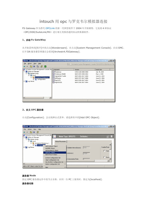
1、启动Fs GateWay从开始菜单的[程序]中的点击[Wonderware],在点击[System Management Console],启动SMC。
打开DA服务器管理器后会看到[ArchestrA.FSGateway]。
2、定义OPC服务器右击[Configuration],会出现弹出式菜单,请选择其中的[Add OPC Object]。
服务器Node指定OPC服务器运作中的节点名称。
在同一台PC上使用时,指定为[localhost]。
服务器名称指定OPC服务器的Prog.ID。
例如,本公司的MELSEC OPC Server的Prog.ID为[Takebishi.Melsec]。
# 不需要变更其他的设定。
3、定义OPC的组右击上述OPC服务器的定义(如果为图像表示时,[New_OPC_000]),会出现弹出式菜单,选择其中的[Add OPCGroup Object]。
Update Rate指定PLC的polling周期。
# DDE的主题名为:端口名称+ "_" + 组名称# 不需要变更其他的设定。
Browse OPC Item点击这个按钮,会出现一个浏览OPC服务器的对话框,通过拖拽操作可以进行标签登录。
选中拖入的标签,然后点击下方的,出现一个在Itemname中默认,不要填写任何就可以,直接点ok,添加完成后,回到前面,点击device items中就会出现选择好的标签名,然后双击选中一个名字,复制,在下面的与intouch链接中需要用到4、定义InTouch的访问名称从InTouch的[系统]菜单中选择[访问名称]。
点击[添加]按钮,会出现下图的画面,从而进行OPC访问名称的定义。
Logix5000 软件PLC培训使用手册

AB -Logix5000 PLC 使用培训教程目录第一章AB PLC使用介绍第一节 BOOTP软件的应用以太网模块在第一次使用时里面没有IP地址,只有物理地址即MAC地址,需要用户给以太网模块分配IP地址。
现在来介绍如何用BOOTP软件给以太网模块设置IP地址。
注意只有没有IP地址的以太网模块才可以用BOOTP软件,如果已经有了IP地址修改IP地址,BOOTP软件是不适用的。
按如下步骤1、找到BOOTP软件可以在RSLogix5000软件的TOOLS里找到也可以在开始菜单里找到如下图在使用bootp软件之前要把本地网络IP地址设置成固定IP和最终想设置的以太网模块地址是同一个网段。
不能是自动获取。
2、然后打开BOOTP-DHCP-Server出现如下图所示,白色对话框里是自动扫描到的MAC地址。
3、然后双击MAC地址会出现如下4、在IP地方输入IP地址5、点击OK出现如下图6、使IP地址部分高亮然后电机按钮直到Status处出现commad successful此时已经把以太网模块的IP地址设置成动态的,断电后还会丢失(注意:有时候需要点击多次才能成功是正常的)然后在点击按钮,直到Status处出现commad successful此时IP地址已经设置成静态的。
7、用BOOTP设置IP地址完毕第二节RSlinx通讯软件介绍RSlinx是通讯软件,用于建立PLC和PC之间的通信。
下面我们将介绍通过DF1通信协议以及ENthernet IP协议,建立计算机和PLC的通信。
一、通过DF1通信协议建立计算机和PLC的通信步骤如下:1.打开RSlinx,可以按如下的路径打开,或者是直接点击右侧任务栏下的图标。
RSlinx打开后出现如下界面:2、打开RSlinx后,直接点击图标,即上图标注出的Configurate drives,或者是通过Communications>Configurate drives,3、将下拉箭头展开,出现如下界面:4、选择RS-232 DF1 devices,然后选择Add New按钮,点击OK5、注意在Comm下,若是编程电缆直接和电脑的串口相连,则用默认的COM1,若是采用了USB转串口,则需根据实际情况选择相应的串口,确认Comm,如下图所示。
罗克韦尔软件安装
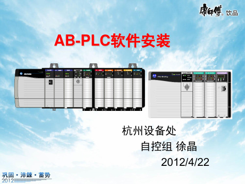
点击“下一步”后请选择 “我同意”继续安装
4-6 通讯软件RSLINX安装
提示输入序列号,任意输入 10位数字后点击“下一步”
4-7 通讯软件RSLINX安装
点击“下 一步”
4-8 通讯软件RSLINX安装
点击“安装”进入正式安装
4-9 通讯软件RSLINX安装
正在安装EDS文件,持续 大约3分钟。
安装过程中会提示:因为 通讯软件未安装导致软件 安装失败,请点击“确定” 后继续安装,圈选打叉的 是未能安装成功的软件。
2-22 RSLogix 5000 安装
对话框提示,请选择 “忽略”后跳转到是 否选择现在激活产品, 请选择不激活产品。
2-23 RSLogix 5000 安装
点击“完成”; RSlogix5000软件安装 完成。
RSNetworx 网络组态 软件
其它软件
RSLinx 通讯平台
RSLogix Emulate 5K 仿真软件
2-1 RSLogix 5000 安装
双击文件夹
2-2 RSLogix 5000 安装
双击文件夹
2-3 RSLogix 5000 安装
双击安装程序setup.exe
2-4 RSLogix 5000 安装
5-9 软件激活
请点击 “Move” 请点击 “OK”
6、小结
• 罗克韦尔编程软件、通讯软件、仿真软件、 软件激活已完成安装。 • 安装罗克韦尔其他软件时有的需要退出通 讯软件和杀毒软件才能安装成功。 • 三个软件的安装顺序没有严格要求,可以 尝试其他顺序安装。 • 全部安装过程持续约60分钟。
双击“Prvdisk” 弹出对话框,请 选择并点击“连 接”进入下一步 操作
5-4 软件激活
罗克韦尔自动化企业工具包和支持用户指南说明书
Enterprise Toolkit GuideWelcomeOverviewEnterprise Toolkit Contents Activation FAQTelephone SupportOnline SupportSoftware, Firmware and Other Updates Support OptionsInternational Numbers7International NumbersLegacy Toolkit: For customers who require access to RSVeiw32, Historian Classic, SoftLogix, Studio 5000 Legacy for v20.04 and below select the Legacy Toolkit “buy with” option when you shop for the Enterprise Toolkit. The Legacy Toolkit provides you with the appropriate activation certificate required to use the software highlighted above.Note: All Toolkit software is subject to limitations as described in the license agreement.1 Enterprise Toolkit Contents*Denotes product serial number indicated on toolkit activation certificate is the parent serial number to download all activationsEnterprise Software Toolkit Bundle Contents - Named & ConcurrentWhat is Media?Media is an electronic image of all software that is available for additional purchase at time of Toolkit purchase. Media is provided for your internal development use only, and external customer distribution is prohibited. Distribution to customers may result in program termination.• You will have activations to the products that are included in the license type purchased by your company (see your Contents document). Please Note: The media provided is propertyof Rockwell Automation and may not be resold, transferred, or used in a production or manufacturing capacity.Who can use media?Media is restricted to use of the toolkit owner. External customer distribution is prohibited. Distribution to customers may result in program termination.Is media included in the Toolkit?No. Media is optional and can be purchased when the Toolkit subscription is renewed at the end of each contract period.Can I use media to update my customers?Media is for internal development use only and is not intended for end customer use. Distribution to customers may result in program termination. Where can I find product release notes and system requirements?https:///What if a product revises between media releases?https:///Will I be able to activate all products included in the media?No. Which products you can activate depends on the contents of your license. Some products have third-party licensing restrictions prohibiting inclusion in internal development licenses. However, these products may be included on media for update and demo purposes.What do I need to activate my software electronically?To activate your software electronically you will need:• A computer with an Internet connection and web browser (or email, telephone, or fax capability).• FactoryTalk Activation Manager software (the FactoryTalk Activation Manager software application is included on your media if you purchase).• The software serial number and product key (printed on the Activation Certificate document, enclosed in a red envelope included with the software media).Who do I call if I need activation support?Please access Technical Support athttps:/// or by phone using the numbers provided on pages 9-10. How do I Lock or UnLock a Serial Number? Request via Tech Support. Go tohttps:/// Rockwell Automation Tech Support ... 24 x 7 around the globe! (). Select Chat & Submit a Question. Select the FactoryTalk Activation ? icon. Select “I have a different question and would like to submit it”, then Next. In “Please enter a short title for your ticket”. Enter: Lock to Mail or UnLock to Email. In “What information do you want to pass to the Rockwell Automation Support Engineer?” Enter the applicable Serial Number(s). A ticket will be created and you will be notified when complete.2Activation FAQWhere can I find tutorials on FT Activation? You can access FAQs, tutorials, and view archived Q&As online at our Activations site https:///What if I need help installing a product?Start with the Rockwell Automation Knowledgebase for 24/7 technical information and assistance:• View technical/application notes• Obtain software patches• Ask questions, and much more!• Subscribe for product/service emailsWhat is Lock to Email?Toolkit owner can control activation distribution to users by setting Lock to Email On. Lock to Email requires the user to activate to an internet computer. The owner or administrator assigns users the explicit number of activations they will receive. The user will receive an email to activate. The user must use the “Activate Software” button to activate. Direct use of FactoryTalk Activation Manager is inhibited. For dongle activations or deployment to a disconnected system, Lock to Email must be OFF and the use Serial Number and Product Key with FactoryTalk Activation Manager is required.Will my Toolkit have one serial number with FactoryTalk Activation?Yes. You will have one serial number per Toolkit catalog number ordered. A Toolkit license serial number includes individual activation keys for the software products contained in the bundle. Your Toolkit license may include multiple installs under the same serial number depending on the number of installs purchased.Where can I find product manuals and release notes?The Rockwell Automation Technical Reference Library is included on media, and contains product manuals, technical notes, and Knowledgebase files for on-demand installation assistance.What is the minimum version of the FactoryTalk Activation Tool I need to use with my Toolkit?We encourage participants to use the latest version of FactoryTalk Activation Manager. The latest version of FactoryTalk Activation Manager can be downloaded from our website at https://How is the Toolkit license activated?The Toolkit license uses FactoryTalk Activation. FactoryTalk Activation is part of the Rockwell Automation FactoryTalk Services Platform. It allows FactoryTalk enabled products to be activated via files generated by Rockwell Automation over the Internet. It eliminatesthe dependency on physical media to initiate activation. As a result, software activations can be delivered, distributed, stored, backed-up and moved electronically. Activation files are hosted to your local server, machine, or a USB dongle. For help with activation, click Help in the upper right corner of the FactoryTalk Activation Manager, or visit our Activations Support site at at https://2Activation FAQ continued…How to ContactImmediately address issues with phone support. These specialists are ready when you need them. Please access Technical Support athttps:/// or by phone using the numbers provided on pages 9-10. Once your contract is active, you will receive a designated authorization number that can be found within their Welcome Kit (wallet cards) and/ or within their account profile on Knowledgebase. Please use your designated Authorization Number (and phone number if you purchased System Support) when calling for support. These numbers can only be used for support issues regarding products included in the Toolkit Program support offering.Standard phone support hours are 8 am to 5 pm Monday through Friday in the time zone of the primary participant location unless a 24x7x365 support level was purchased.You will receive an e-mail containing your toolkit support entitlement information and credentials via PDF attachment following the toolkit order shipment. The PDF is formatted to print directly onto Avery Stock Number 5371, so you canprint cards to carry with you and/or distribute electronically to your engineers who use the Toolkit software.Please allow 5-7 days for receipt. The registered participant site will be able to use the Toolkit serial number to obtain telephone support in the interim.• If you want to ask questions and/or need support regarding issues that have a direct impacton your operation or business, you should categorize the urgency as HIGH. In high urgency situations, your system or process should remain operational but at less than full capability. In these situations, you require immediate or same day resolution if possible.• If your system or process is down and you require an immediate response, you should communicate this status to the telephone support specialist directly and classify it as VERY HIGH. In these situations, we leverage additional technical support and engineering resourcesto resolve your issue quickly. We expect you to implement technical support recommendations and to be available for immediate follow-up.If this does not occur, we may downgrade the urgency of your situation.*Phone Support is not available onRockwell Automation observed holidays unless you have elected for 24x7x365 support. A list of these holidays for all regions can be found via the Knowledgebase in article #819086.Maximize the Value of Your CallWhen you call for support, we will ask you for the following information which you will wantto have available:• TechConnect Support agreement authorization number• You can find this on your eWallet Cards• If you cannot locate this number, we will ask you for your name and company site location.• Product name(s), description and series/ revision/version number• System configuration and components, e.g., operating system, etc.• Sequence of events prompting your call• Complete error message if applicableIn addition, you should communicate to the telephone support specialist who answers your call the urgency of your situation so that we can respond appropriately. Use the following as a guide:• If you want to ask questions and/or need support regarding issues that have minimal or no immediate impact on your operation or business, you should categorize the urgency as MEDIUM. In normal situations, you agree that it is acceptable if your issue is not resolved on an initial call.Make CallsUse the designated telephone support number listed on your support entitlement e-mail and wallet cards, or refer to this guide for a list of International Numbers. You can use this number only to request support on product included in the Toolkit TechConnect support offering. In general, standard telephone support hours are from 8:00 am to 5:00 pm Monday through Friday in the time zone of the participating location listed on your support entitlement e-mail, unless you purchased a 24x7x365 support option. Standard telephone support hours may vary according to your region. Refer to your support entitlement email for specific in ormation. Note: 24x7 Support is not currently availableon certain products, such as FactoryTalk ProductionCentre, certain Safety products and KEPServer Enterprise. Toolkit Support does not include Legacy Support. Participants may purchase a Legacy Support contract through your local Rockwell Automation sales or Authorized Distributor.PACKAGED SOLUTIONS RAPID Line Integration™ 007PLANTPAX PlantPAx®008ACTIVATIONSoftware Activations, Copy Protection, Software Download Issues 010CONTROLLERSControlLogix®, FlexLogix™, GuardLogix®,Communications, Associated I/O and Instruction Set 100CompactLogix™, Compact GuardLogix®, Communications, Associated I/O and Instruction Set101DIAL MENU DIRECT DIAL MENU DIRECTFactoryTalk® View ME, RSView® ME, PanelView™ Plus Graphic Terminals, Studio 5000 View Designer® and PanelView™ 5500202PanelView™ Classic, Standard, Enhanced Terminals and PanelBuilder™ Software203PanelView™ Component and PanelView™ 800 204Message Displays205Industrial Computers and Monitors 206NETLINXDeviceNet, ControlNet, EtherNet/IP and Associated RSNetWorx™ Software300RSLinx ® Classic, RSLinx® Enterprise and FactoryTalk Linx301Call the Rockwell Automation U.S. Customer Support Center:1.888.382.1583 (toll free) or 1.440.646.3434Monday through Friday from 8:00am to 6:00pm ET.Direct Dial NumbersFor customers with Active TechConnect SMand Integrated Service Agreement Support agreementsFor online technical support:https:///app/phoneSelect Option 3Technical Support1 Select Option 5More options2Enter the three digit code from the tables below.3The KnowledgebaseThe Rockwell Automation Support Center https:// is your online resource for technical information, support and assistance. Increase your productivity by finding solutions to technical questions more quickly – saving both time and money.Maintained by the same engineers who provide your TechConnect Support, the Support Center houses the Knowledgebasehttps://,an online database that we update with the hardware and software solutions from actual support service tickets.The Knowledgebase, included with all TechConnect support agreements, provides you with access to over 70,000 technical notes, documents and solutions. In addition, you can submit questions and chat live with our Technical Support engineers in your local language. Create an AccountTo begin using your TechConnect Support contract, you need to create an account. For information about how to create an account watch the video tutorial posted to the Support Center under the Support Center Training menu or use the job aid posted in Knowledgebase Answer 452148.IMPORTANT NOTE:Use your email address as your user name and anything you want as a password. Enter your support authorization number into your account profile to gain full access to all Knowledgebase documents and features.You can locate your support authorization number on your e-Wallet Cards.Search KnowledgebaseFor information about how to search the Knowledgebase, watch the video tutorial posted to the Support Center under the Support Center Training menu or use the job aid posted in Knowledgebase Answer 452148.Explore ForumsOur forum community offers peer to peer support on a wide range of topics. You can search foran answer, offer a solution or start your own forum discussion. For information on how to use the forums, watch the video tutorial posted to the support center under the Support Center Training menu or use the job aid posted in the Knowledgebase Answer 452161.Submit QuestionsThe Submit Questions feature lets you email you email a question on a specific product to a tech support engineer. For information about howto search the Knowledgebase, watch the video tutorital posted to the Support Center under the Support Center Training menu or use the job aid posted in Knowledgebase Answer 44451.Your question is assigned a service ticket number. Our targeted email response time for TechConnect customers is 24 business hours.IMPORTANT NOTE: The ‘Submit a Question’ feature is only available when you have entered your TechConnect Support authorization number into your account profile as described in the ‘Create an Account’ section.If you need immediate assistance, do not submit an online support request. Instead, call the telephone number listed on your e-Wallet Cards (you must have purchased a toolkit with one of our available phone support options to qualify for phone support).4 Online Support4 Online Support continued…Chat LiveMobile friendly and available 8am-5pm local time, chat live with our engineers for expedited issue resolution. Visit the Knowledgebase to chat live with Tech Support engineers athttps:///app/ chat/chat_launchFor information about how to chat, watch the video tutorial posted to the Support Center under the Support Center Training Menu or use the job aid posted in Knowledgebase Answer anize Your InformationFind My TechConnect acts as your personal information library. For information about how to use this feature, watch the video tutorial available at https://rockwellautomation.custhelp. com/app/answers/answer_view/a_id/35770/loc/ en_US#__highlightObtaining UpdatesThe Toolkit Support contract enables you to download software updates via the Web for the products included in your Toolkit license. Please go to https:/// To download software or firmware updates, hot fixes or patches, navigate tohttps:///and select “Compatibility and Downloads” section from the left hand navigation.For More InformationVisit https:///en-us/support.html or refer to the following websites for additional information about Rockwell Automation products and programs: Software Registration Transfer:https:///Remote Support Programs:/services/ onlinephone FactoryTalk® Activation SupportIf you experience a hard disk failure or an activation related problem, you should contact Rockwell Automation Technical Support at https:///en-us/ support.html or by phone using the call in numbers listed on page 15. See this Guide for a list of international numbers by country and region, or use our Worldwide Locator online at https://Get Activation Support without picking up the phone! Online activation support, including Live Chat, Reference and FAQ documents, and Activation Forum is available on the Rockwell Automation Knowledgebase. Go to https://5 Software, Firmware, and Other UpdatesReceive unlimited access to Rockwell Automation technical support engineers for real-time phone and electronic support. With deep knowledge of our hardware and software products, and remote desktop technology, our engineers can help you install, configure and maintain equipment and software, obtain software updates, diagnose and fix operating problems and perform basic programming tasks.System Support M-F, 8-5With System Support, your calls are routed to a specialized group of technical support engineers who are trained to support your overall Rockwell Automation control system. You receive a dedicated, single point of contact who will own the ticket from start to finish and follow up to ensure your issue has been resolved. In addition, you gain access to a monthly series of Webinars to stay up-to-date on new products and offerings. System Support is available for both 8-5 and 24x7 support levels.Standard phone support hours are 8:00 am to 5:00 pm Monday-Friday (in time zone of the primary participating location) for TechConnect Support.System Support 365x24x7For companies needing support after 5pm or over the weekend for special projects or start-ups across the region, this option extends your hours of coverage to include weekends and holidays. Note: 24x7x365 support is not currently available on certain products, such as FactoryTalk ProductionCentre and KEPServer Enterprise. Toolkit Support does not include Legacy Support or Process Safety Support coverage. Participants may purchase a Legacy Support or Process Safety Support contract at a suggested discount through your local Rockwell Automation Distributor or Rockwell Automation sales office. *Phone Support is not available onRockwell Automation observed holidays unless you have elected for 24x7x365 support. A list of these holidays for all regions can be found via the Knowledgebase in article #819086.6 Support Options7 International NumbersThis User Guide is designed for global use. For local language information or support you may call the Customer Support number for your country. If your country is not included in the following list, please call the number listed for your region.Connect with us.AADvance, Allen-Bradley, Anorad, ArmorBlock, ArmorConnect, ArmorStart, AutoMax, CENTERLINE, CenterONE, CIRCE, CNC, CompactLogix, Connected Components Workbench software, ControlLogix, Datapac, DriveExecutive, DriveExplorer, Dynamix, Emonitor, Enpac, Enshare, Enwatch, expanding human possibility, FactoryTalk, FactoryTalk Activation, FactoryTalk AssetCentre, FactoryTalk Batch View, FactoryTalk Batch, FactoryTalk eProcedure, FactoryTalk Gateway, FactoryTalk Historian Site Edition, FactoryTalk Historian, FactoryTalk Linx, FactoryTalk Network Manager, FactoryTalk Transaction Manager, FactoryTalk VantagePoint EMI, FactoryTalk View ME, FactoryTalk View SE, FlexLogix, Flex I/O, FORCE, GML, GuardLogix, IM/PACT, IntelliCENTER, iTrak, Kinetix, LifecycleIQ, MachineAlert, MagneMotion, MaterialTrack, MegaDySC, Micro800, MicroLogix, MiniDySC, MultiSight, OneGear, OptiSIS, PanelBuilder, PanelView, PanelView 5500,PanelView 800, PanelView Classic, PanelView Component, PanelView Plus, PhaseManager, Pico, PlantMetrics, PlantPAx, PlantPAx, PLC-2, PLC-3, PLC-5, Point I/O, PowerBrick,PowerControl Builder, PowerFlex 1557, PowerFlex, PowerMonitor, ProcessLogix, ProductionCentre, ProDySC, RAPID Line Integration, Reliance Electric, RSBatch, RSBizWare, RSBizWare Historian, RSBizWare, RSBizWare Scheduler, RSFieldbus, RSLinx, RSLinx Classic, RSLinx Enterprise, RSLogix 500, RSLogix 5000, RSLogix Emulate 5000, RSLogix, RSMACC, RSNetWorx, RSPower, RSSql, RSTestStand, RSView, RSView ME, RSView SE, RSView32 Active Display System, RSView32 WebServer, RSView32, Scheduler, SequenceManager, SLC, SLC 500, SMC, SoftLogix, Stratix, Studio 5000 Architect, Studio 5000 Logix Designer, Studio 5000, Studio 5000 View Designer,TechConnect, ThinManager, Trusted, Ultra, VantagePoint and XM are trademarks of Rockwell Automation, Inc.Trademarks not belonging to Rockwell Automation are property of their respective companies.Publication SYSINT-SP007F-EN-P - September 2023 | Supersedes Publication SYSINT-SP007E-EN-P - June 2023。
plc控制器软件操作说明
软件操作说明时间:2011-09-18编程软件操作说明上海东屋电器有限公司自控部在化学水和除灰除渣系统中主要使用了RSLogix5000 编程软件和RSLinx 通讯软件,SLogix5000 编程软件是针对程序的编制、更改、监控所使用的,RSLinx 通讯软件是针对上位机与PLC 之间的通讯所使用的,当RSLinx 通讯软件出现故障,那么PLC 与上位机中的画面和程序将不能通讯。
一、RSLinx 的配置和使用首先在点击电脑的开始菜单------程序------Rockwell Software------RSLinx-----RSLinx Classic,RSLinx 程序即运行在电脑右下任务栏中RSLinx 软件,点击图标,点击此图标对软件进行配置。
打开弹出Configure Drivers 驱动配置窗口,点击此出的下拉菜单,选择Etherner/IP Driver,然后点击右边的Add New 按钮,弹出点击OK,弹出Configure driver 的窗口(其中AB_ETHIP-2 这个名字是默认名字,也可以自行修改),在此窗口中选中点击确定(中间的IP 无需设置)完成通讯配置。
点击弹出在线检测的出的所有硬件配置,此时表明通讯配置正常。
编程软件操作说明上海东屋电器有限公司自控部完成以上步骤后使用RSLogix5000 编程软件就可以连上PLC,就可对PLC 进行监控和操作。
要与人机界面通讯,还需在以上的配置中进行其他配置的添加,具体操作如下:点击,在窗口菜单中点击DD E/OPC----Topic configuration,在Topic configuration的对话框呢,点击date Source,先NEW 一个名字,在Topic list 框内显示一个NEW_TOPIC 的默认名字,然后把这个名字改成huashui,然后在date Source 下面的框内点击AB_ETHIP-2,选中之后点击,在Processor Type 框内选择RSlogix5000,然后勾上Use Symbols 前的复选框,然后在填上程序所在的位置,如图,其他不要修改,最后点击,在communications driver 下拉框内选择前面配置的驱动设备AB_ETHIP-2,依次点击APPLY-----DONE,完成对其的通讯配置。
罗克韦尔自动化 FLEX 5000 数字量 16 点 120V AC 输入模块 安装指南说明书

安装指南FLEX 5000 数字量 16 点 120V AC 输入模块产品目录号 5094-IA16、5094-IA16XT产品概述5094-IA16 和 5094-IA16XT 数字量 16 点 120V AC 输入模块用于检测现场设备中的输入转换。
即,这类模块用于检测输入状态何时从 OFF 变为 ON 或何时从 ON 变为 OFF 。
输入模块将输入状态转换信号转换为在控制器中使用的相应逻辑电平。
FLEX 5000™ I/O 模块采用生产者 - 消费者通信模式。
生产者-消费者通信模式是模块与其他系统设备之间的一种智能数据交换,在通信过程中,每个模块都会生成数据,而不是先被轮询。
FLEX 5000 I/O 模块与一些 Logix 5000™ 控制器配合使用,并通过 Studio 5000 Logix Designer® 应用程序进行配置。
有关Logix 5000 控制器和 Logix Designer 应用程序版本与 FLEX 5000 I/O 模块兼容的更多信息,请参见第12页的“其他资源”中列出的出版物。
主题页码关于模块5准备事宜5所需组件5安装模块7安装终端盖7给端子座接线8断开与端子座的连线9接线图10为系统供电10拆卸模块11更换模块11模块技术参数11其他资源122罗克韦尔自动化出版物 5094-IN025A-ZH-P - 2019 年 12 月FLEX 5000 数字量 16 点 120V AC 输入模块 安装指南ATTENTION:Read this document and the documents listed in the Additional Resources section about installation, configuration and operation of this equipment before you install, configure, operate or maintain this product. Users are required to familiarize themselves with installation and wiring instructions in addition to requirements of all applicable codes, laws, and standards.Activities including installation, adjustments, putting into service, use, assembly, disassembly, and maintenance are required to be carried out by suitably trained personnel in accordance with applicable code of practice. If this equipment is used in a manner not specified by the manufacturer, the protection provided by the equipment may be impaired.注意:在安装、配置、操作和维护本产品前,请阅读本文档以及“其他资源”部分列出的有关设备安装、配置和操作的相应文档。
罗克韦尔软件安装资料

3-6 仿真软件RSEMU5000 安装
系统默认的是典型安装,无需选 择,依次点击“下一步”、“安 装”进入正式安装
3-7 仿真软件RSEMU5000 安装
提示进行EDS文件安装, 点击“确定”开始安装
3-8 仿真软件RSEMU5000 安装
提示安装完成,请点击“完 成”;RSEMU5000安装完 成。
安装过程中会提示:因为 通讯软件未安装导致软件 安装失败,请点击“确定” 后继续安装,圈选打叉的 是未能安装成功的软件。
2-22 RSLogix 5000 安装
对话框提示,请选择 “忽略”后跳转到是 否选择现在激活产品, 请选择不激活产品。
2-23 RSLogix 5000 安装
点击“完成”; RSlogix5000软件安装 完成。
点击“下一步”后请选择 “我同意”继续安装
4-6 通讯软件RSLINX安装
提示输入序列号,任意输入 10位数字后点击“下一步”
4-7 通讯软件RSLINX安装
点击“下 一步”
4-8 通讯软件RSLINX安装
点击“安装”进入正式安装
4-9 通讯软件RSLINX安装
正在安装EDS文件,持续 大约3分钟。
点击“继续”开 始安装
2-5 RSLogix 5000 安装
点击 “下一 步”
2-6 RSLogix 5000 安装
要求输入序列号
2-7 RSLogix 5000 安装
输入任意10位数字, 点击“下一步”
2-8 RSLogix 5000 安装
提示序列号无 效,可以不理会, 点击“继续安装”
2-9 RSLogix 5000 安装
状态条至90%时会弹出 对话框,请点击 “Next”继续安装
罗克韦尔PLC系统操作站软件安装及配置作业指导书

罗克韦尔PLC系统操作站软件安装及配置作业指导书目录一、操作站操作系统的安装及配置 (3)二、 RSlink软件的安装 (6)三、系统组态软件RSlogix5000或RSlogix500的安装 (10)四、项目组态软件RSView32或RSView SE的安装 (19)五、系统放权利文件 (28)六、系统网络配置与项目通道配置(RSview32) (32)七、添加系统EDS文件 (41)八、操作站备份 (43)罗克韦尔PLC系统操作站软件安装及配置作业指导书AB PLC是我厂最主要的三大控制系统之一,应用比较广泛,系统操作站的维护工作工作也显得尤为重要,操作站相关软件的安装及配置也是日常维护中经常要进行的工作,是必须要掌握的技能之一。
罗克韦尔PLC系统(以下简称AB系统)需要安装的软件主要有程序组态软件RSlogix5000或RSlogix500;项目组态软件RSview32或SE;网络组态软件RSlink。
系统操作站的安装和配置应当按照以下顺序进行:1、操作系统的安装和配置;2、网络组态软件RSlink的安装;3、程序组态软件RSlogix5000或RSlogix500的安装;4、项目组态软件RSview32或SE的安装;5、系统放权利文件;6、系统网络配置与项目通道配置(RSview32);7、添加系统EDS文件;8、操作站桌面锁设定与整体备份。
以上步骤中3和4的顺序可以颠倒,其他步骤必须按顺序进行。
下面就各个软件的安装及操作站的配置步骤进行详细介绍:一、操作站操作系统的安装及配置目前AB系统操作站的操作系统主要是windows XP,要安装系统软件首先需要安装操作系统,并对操作系统进行简单的设置。
第一步:XP操作系统的安装及基本配置。
操作系统的安装只需按照基本的系统安装步骤进行即可,这里不再详细的介绍安装过程,需要注意的是如果是新硬盘需要对硬盘分区并格式化,最少需要分两个区,便于后期程序和系统的备份恢复,系统盘最少分配10GB。
罗克韦尔软件安装注意事项
罗克韦尔软件安装注意事项罗克韦尔软件是一种用于工业自动化控制系统的软件,安装时需要注意以下几点:首先,在安装罗克韦尔软件之前,需要先确保计算机的基本配置符合软件的要求。
罗克韦尔软件通常对计算机的操作系统版本、处理器类型和内存大小等有特定的要求,因此在安装前需要对计算机进行系统检查,确保其能够满足软件的运行条件。
其次,安装罗克韦尔软件时需要使用管理员权限登录计算机。
由于罗克韦尔软件需要对计算机的一些系统配置进行修改,因此只有以管理员身份登录的用户才能正确完成安装过程。
如果以普通用户身份登录计算机,则可能无法进行必要的操作,导致安装过程失败。
再次,安装罗克韦尔软件时需要关闭一些可能会干扰安装过程的程序。
罗克韦尔软件通常需要访问计算机的一些系统资源,如端口和驱动程序等,因此在安装过程中应尽量关闭其他可能占用这些资源的程序,以确保安装过程的顺利进行。
比如,关闭杀毒软件、防火墙等可以提高软件安装成功的几率。
另外,安装罗克韦尔软件之前,需要先准备好软件安装包以及相应的授权证书。
罗克韦尔软件通常是商业软件,需要购买授权才能合法使用,因此在安装前需要先获得相应的授权证书。
同时,还需要确保软件安装包是正确的版本,以免安装错误的软件版本导致不必要的问题。
最后,在进行罗克韦尔软件的安装时,还需要根据软件提供的安装向导逐步进行操作。
安装向导通常会指导用户进行一系列的配置和选择,如选择安装路径、添加必要的组件和驱动程序等。
在操作时要根据向导的提示进行,确保每一步都正确完成,以避免安装过程中的错误。
总之,罗克韦尔软件的安装是一个相对复杂的过程,需要用户仔细操作,并且满足一些特定的要求。
只有正确地安装罗克韦尔软件,才能保证软件的正常运行和工业自动化控制系统的稳定运作。
因此,在进行安装前需要提前了解相应的安装注意事项,并按照要求进行准备和操作。
罗克韦尔21版本程序安装教程

罗克韦尔21版本程序安装教程罗克韦尔21版本程序安装教程步骤一:下载安装程序•打开罗克韦尔官方网站•导航到下载页面•点击“罗克韦尔21版本程序下载”按钮•等待下载完成步骤二:运行安装程序•找到下载的安装程序文件•双击运行安装程序•如果系统提示是否允许此程序进行更改,请点击“是”•程序安装向导将自动弹出步骤三:选择安装选项•在安装向导中,阅读并接受许可协议•如果有定制选项,请根据需求进行选择•点击“下一步”继续步骤四:选择安装位置•默认情况下,安装程序会选择一个默认的安装路径•如果需要更改安装路径,点击“浏览”按钮,选择新的目录•确认安装路径后,点击“下一步”继续步骤五:选择组件•在此步骤中,可以选择需要安装的组件•建议根据需求勾选相关组件•点击“下一步”继续步骤六:等待安装完成•安装程序将开始安装选定的组件和文件•等待安装过程完成•过程中不要关闭安装程序或者电脑步骤七:完成安装•安装完成后,在安装向导中将显示安装成功信息•点击“完成”按钮退出安装向导步骤八:运行罗克韦尔21版本程序•在开始菜单或者桌面上找到罗克韦尔21的图标•双击运行程序•程序将启动并进入初始设置界面,按照提示进行设置和配置即可以上就是“罗克韦尔21版本程序安装教程”的详细步骤。
根据这个教程,您应该能够顺利地安装和运行罗克韦尔21版本程序。
如有问题,请查阅罗克韦尔官方网站或者咨询其它相关资源。
步骤九:卸载罗克韦尔21版本程序•如果您需要卸载罗克韦尔21版本程序,可以按照以下步骤进行操作:在Windows系统上卸载罗克韦尔21版本程序•在开始菜单中找到“控制面板”,点击打开•在控制面板中,找到“程序”或“程序和功能”,点击打开•在程序列表中,找到罗克韦尔21版本程序,右键点击选择“卸载”•按照提示完成卸载过程在Mac系统上卸载罗克韦尔21版本程序•在应用程序中,找到罗克韦尔21版本程序的图标•将图标拖到废纸篓中,或者右键点击选择“移除到废纸篓”•在废纸篓中,右键点击选择“清空废纸篓”•确认删除程序注意:卸载罗克韦尔21版本程序将会删除与该程序相关的所有文件和设置。
罗克韦尔(rockwell)工控软件入门介绍

新建 RSLOGIX5000 工程
输入处理器的名称 提示:这里处理器 的名称将在Rslinx中 显示
名称要求能够反映一定的信息,比如地点、功能等 在其中输入“Slot1”
新建 RSLOGIX5000 工程
选择机架类型
提示:Controllogix 系列机架主要有4槽、 7槽、10槽、13槽、 17槽
通过本节的学习,必须要达到能够多种方式配置驱动的目的 下面将以EtherNet驱动配置为例
•创建RSLOGIX5000工程
– – – – – – 创建工程文件 配置IO 浏览TAG 编制程序 下载调试 在线编辑功能
通过本节的学习,必须要达到能够新建工程、配置IO模块等入门操作 下面将详细描述流程
RSLINX 配置详细步骤实列
菜单栏
标准图示栏
在线栏
指令工具栏
工程目录
梯形图窗口
结果显示窗 状态栏
安装RSLogix500
•第一步: 安装RSLINX
屏幕剪辑的捕获时间: 2008-5-2, 17:11
•第二步: 安装RSLOGIX500
• • • • • • • 打开计算机,启动操作系统 在光驱中插入Rslogix500光盘 按提示一步步安装 输入10个数字“1234567890” 完成安装 激活软件 如果有以前的版本先卸载再重新启动计算机然后再安装
CommunicationRSWHO 或者
RSLINX 配置详细步骤实列
RSLINX树型网络结 构,可以点击“+” 或者双击设备来展 开网络;点击“-” 或双击缩回结构
CommunicationRSWHO 或者
RSLINX 配置详细步骤实列
显示对应网络中所 有设备
CommunicationRSWHO 或者
罗克韦尔21版本程序安装教程
罗克韦尔21版本程序安装教程【实用版】目录1.罗克韦尔 21 版本程序简介2.安装前的准备工作3.安装步骤详解4.常见问题与解决方法5.结束语正文【罗克韦尔 21 版本程序简介】罗克韦尔 21 版本程序是一款广泛应用于计算机领域的软件,它以其强大的功能和便捷的操作赢得了广大用户的一致好评。
为了帮助用户更好地安装和使用该程序,本文将为大家详细介绍罗克韦尔 21 版本程序的安装过程。
【安装前的准备工作】在开始安装罗克韦尔 21 版本程序之前,请确保您的计算机满足以下条件:1.操作系统:支持 Windows、Mac OS 和 Linux 等主流操作系统;2.硬件要求:处理器至少为 Intel Core i3,内存至少为 4GB,硬盘空间至少为 10GB;3.安装环境:请确保您的计算机上已安装了最新的.NET Framework。
【安装步骤详解】接下来,我们将分步骤介绍如何安装罗克韦尔 21 版本程序:步骤一:下载安装包访问罗克韦尔官方网站,选择适合您计算机操作系统的安装包进行下载。
请确保下载的安装包是正版且未被篡改。
步骤二:运行安装包下载完成后,双击安装包图标,开始运行安装程序。
步骤三:选择安装目录在安装向导中,您可以选择将罗克韦尔 21 版本程序安装到计算机上的任意目录。
建议将程序安装在非系统盘,以避免影响操作系统的稳定性。
步骤四:安装过程中,请务必保持网络连接畅通安装过程中,程序需要从官方网站下载部分组件。
请确保网络连接畅通,以免安装失败。
步骤五:完成安装安装完成后,您可以在开始菜单中找到罗克韦尔 21 版本程序的快捷方式,点击即可运行。
【常见问题与解决方法】在安装过程中,可能会遇到以下问题:1.安装失败:请检查计算机是否满足安装条件,以及安装包是否为正版。
2.运行时出现错误:请确保计算机上已安装了最新的.NET Framework。
【结束语】通过以上步骤,相信您已经成功安装了罗克韦尔 21 版本程序。
罗克韦尔 TechConnect 支持用户指南 说明书

持支目录欢迎使用3简介4 TechConnect 支持优势概述 4技术支持联系方式5提高电话沟通效率 5在线支持中心创建在线支持中心(知识库)帐户 6 如何搜索知识库 6 浏览论坛 6 如何提交问题 7 与罗克韦尔自动化工程师实时对话 7 TechConnect 支持选项支持选项概述 8 支持选项详细说明 9 其他支持协议(订阅、工具包、ThinManager 等) 10 TechConnect 升级选项 12 产品系列涵盖范围 12 支持交付成果 12硬件校准和维修(仅限 ESAFE 支持)设备校准 13 附件测试和更换 13 设备维修 13 请求校准 13 获取 RMA 13术语表14实用链接15欢迎使用尊贵的客户:恭喜您成功购买 Rockwell Automation® TechConnect SM 支持协议。
我们致力于为您提供对所需工具和资源的即时访问服务,从而协助您进行故障处理并实施与自动化设备性能提升相关的改进。
本手册旨在为您提供便捷服务,充分发挥 TechConnect 支持协议的优势。
请仔细阅读以下信息并保存本手册的副本,以备将来参考。
此外,我们希望您:通过使用此链接注册成为支持中心和知识库的会员:如果您有关于 TechConnect 支持的任何问题,请使用罗克韦尔自动化支持中心提供的查找本地经销商或查找 罗克韦尔自动化销售办事处实用工具。
再次感谢您购买 TechConnect 支持。
我们期待帮助您优化自动化资产的性能,满足您的生产需求并帮您实现业务目标。
此致!罗克韦尔自动化服务部门1201 South Second Street | Milwaukee | WI 53204 | 电话:(414) 382-2000论是快速解决生产问题,改进培训,还是简化软件更新,购买 TechConnect SM 支持协议都能提供应对重大挑战所需的知识和支持。
TechConnect 支持优势 概述通过在线支持解决问题,查询支持历史记录• 在线提交问题,或与经过专业培训的技术支持工程师实时对话• 在个人门户中管理电话和在线交互,接收产品通知并保存偏好内容快速解决问题• 产品专家指导您完成安装、配置和故障处理或诊断技术问题,确保更快恢复设备正常运行• 产品专家全年全天候待命,随时满足您的需求管理培训• 以折扣价购买 Learning+ 订阅式培训课程,满足培训需求并提高员工绩效更好地管理软件更新• 通过获取最新软件更新,帮助预防危机、扩展功能以及提升用户体验通过增强现实技术来更快解决问题• Digital Assist Library 使用增强现实技术,引导您根据相应步骤来完成 Allen-Bradley 产品的维修维护工作• 使用 Live View Support™ 共享实时视频源,资深技术人员可即时查看您的设备,并提供具体、详细的硬件维修指导技术支持联系方式客户仅能获得与其合同中所列产品/软件相关的权益。
罗克韦尔 ControlLogix 模拟量I O模块 说明书

ControlLogix 模拟量 I/O 模块产品目录号 1756-IF16、1756-IF6CIS 、1756-IF6I 、1756-IF8、1756-IR6I 、1756-IT6I 、1756-IT6I2、1756-OF4、1756-OF6CI 、1756-OF6VI 、1756-OF8用户手册重要用户信息在安装、配置、操作或维护设备之前,请仔细阅读本文档及“其他资源”部分列出的文档,了解设备的安装、配置和操作信息。
用户需要了解安装和接线指南以及所有适用规范、法律和标准的相关要求。
包括安装、调整、投入运行、使用、装配、拆卸和维护等在内操作必须由经过适当培训的人员根据适用的操作守则来执行。
如未按照制造商指定的方法使用设备,则设备提供的保护功能可能会受到影响。
任何情况下,对于因使用或操作本设备造成的任何间接或连带损失,罗克韦尔自动化公司概不负责。
本手册中包含的示例和图表仅用于说明。
由于任何具体的安装都存在很多差异和要求,罗克韦尔自动化公司对于依据这些示例和图表进行的实际应用不承担任何责任和义务。
对于因使用本手册中所述信息、电路、设备或软件而引起的专利问题,罗克韦尔自动化公司不承担任何责任。
未经罗克韦尔自动化公司的书面许可,不得复制本手册的全部或部分内容。
在整本手册中,我们在必要的地方使用了以下注释,来提醒您注意相关的安全事宜。
标签可能位于设备上或设备内,可提供特定警示。
Allen-Bradley 、Rockwell Automation 、Rockwell Software 、RSLogix 5000、Logix5000、RSNetW orx 、RSLinx 、PowerFlex 、DeviceNet 、EtherNet/IP 、Data Highway Plus-Remote I/O 和 T echConnect 是罗克韦尔自动化公司的商标。
不属于罗克韦尔自动化的商标分别为其所属公司所有。
警告:用于标识在危险环境下可能导致爆炸,进而导致人员伤亡、物品损坏或经济损失的操作或情况。
罗克韦尔自动化 - Kinetix 5700 电源模块安装手册.pdf - 安装手册说明书
安装手册Kinetix5700 电源模块目录号 2198-P031、2198-P070、2198-P141、2198-P208主题页码关于电源模块1重要用户须知2产品目录号说明3准备事宜3拆除所选电源配置的接地螺丝3安装电源模块5钻孔布置6连接器数据9接线要求12断路器/熔断器技术参数14技术参数15其他资源15关于电源模块带 400 V 级别三相交流输入的 Kinetix® 5700 直流母线 (整流器) 电源分别为运用于7…46 kW 和 10.5…69.2A 功率范围应用的伺服驱动器提供连续输出功率和电流。
有关 ControlLogix® EtherNet/IP 通信模块或 CompactLogix™ 5370 控制器的接线、上电、故障处理和集成方面的详细信息,请参见 Kinetix5700 Servo Drives User Manual (Kinetix 5700 伺服驱动器用户手册,出版号:2198-UM002)。
2 Kinetix 5700 电源模块罗克韦尔自动化出版物 2198-IN009B-ZH-P - 2015年6月重要用户须知在安装、配置、操作或维护本产品前,请仔细阅读本文档以及其他资源部分列出的文档,以了解有关此设备的安装、配置和操作信息。
用户需要熟悉安装和接线说明以及所有适用规范、法律和标准的相关要求。
安装、调节、投入运行、使用、装配、拆卸和维护等活动都需要由经过适当培训的人员遵照适用的操作规范来执行。
如果设备的使用方式与制造商指定的方式不同,则设备提供的保护可能受到影响。
对于由于使用或应用此设备而导致的任何间接损失或连带损失,罗克韦尔自动化在任何情况下都不承担任何责任。
本手册中的示例和图表仅供说明之用。
由于任何特定的安装都存在很多差异和要求,罗克韦尔自动化对于依据这些示例和图表所进行的实际应用不承担任何责任和义务。
对于因使用本手册中所述信息、电路、设备或软件而引起的专利问题,罗克韦尔自动化不承担任何责任。
罗克韦尔软件安装

4-1 通讯软件RSLINX安装
双击文件夹
4-2 通讯软件RSLINX安装
双击安装程序 Setup.exe
4-3 通讯软件RSLINX安装
双击“Required Steps”
4-4 通讯软件RSLINX安装
双击“Install RSLinx Classic”
4-5 通讯软件RSLINX安装
状态条至90%时会弹出 对话框,请点击 “Next”继续安装
2-18 RSLogix 5000 安装
请选择“I Agree”并点击 “Next”
2-19 RSLogix 5000 安装
依次点击“下一步”不必 做选择
2-20 RSLogix 5000 安装
点击“下一步”
2-21 RSLogix 5000 安装
点击“继续”开 始安装
2-5 RSLogix 5000 安装
点击 “下一 步”
2-6 RSLogix 5000 安装
要求输入序列号
2-7 RSLogix 5000 安装
输入任意10位数字, 点击“下一步”
2-8 RSLogix 5000 安装
提示序列号无 效,可以不理会, 点击“继续安装”
2-9 RSLogix 5000 安装
选择“接受许可” 点击“下一步”
2-10 RSLogix 5000 安装
点击“下一步”
2-11 RSLogix 5000 安装
系统默认是“典型”安装,不必更改, 点击“下一步”
2-12 RSLogix 5000 安装
勾选“可选设置”、 “可选工具和文件” 点击“下一步”
2-13 RSLogix 5000 安装
4-10 通讯软件RSLINX安装
点击“完成”后跳至返回 页,请选择“Exit”退出安 装,通讯软件安装完成。
罗克韦尔自动化1397 400-600HP交流线滤波器安装说明书

Installation Instructions IN1397-5.31 September, 1998Allen-Bradley1397 400-600HP AC Line Filter Kit Cat. Nos.1397-LF600User Supplied ItemsYou must provide three (3) pieces of 600V, 14 AWG wire (each approximately 1.2 m (4 ft) in length) to connect the kit to the drive’s AC input bus bars.What This Option Provides This option is intended to be applied when the primary of the drive source power transformer is greater than 2300 V RMS. The AC Line Filter consists of six capacitors, arranged in three pairs of two capacitors connected in series. The kit helps to attenuate high voltage spikes that capacitively couple from the transformer primary to the secondary. Kit installation consists of connecting the capacitor grid from the AC input line to ground of the transformer secondary.What This Kit ContainsEach 1397 - AC Line Filter Kit Includes:Part No. (1)Capacitor Assembly 802278-925R (1)Fuse Block, Triple 49454-19C (3)Fuse (7.5A, 600V 64876-84N (1)Wire Harness 802276-924R (6)Spade Connector (Female)411066-15B (2)M6 x 25 Self Threading Screw 419082-100PJM (6)M4 x 12 Self-Threading Screw 419062-100PGH (2)M6 Star Washer 419064-101SJ (6)M4 Flat Washer 19064-1SG (1)Plastic Cover 802276-920R1397 AC Line Filter Kit 21397-5.31 September, 1998ATTENTION: Electric Shock can cause injury or death. Remove all power before working on this product.The drive is at line voltage when connected to incoming AC power. Before proceeding with any installation or troubleshooting activity, disconnect, lockout and tag all incoming power to the drive. Verify with a voltmeter than no voltage exists at input terminals 181 (L1), 182 (L2) and 183 (L3).You are responsible for conforming with all applicable local, national and international codes when installing this kit.!Ë1Remove, lockout and tag all incoming power to the drive. Ë2Choose an appropriate location for mounting the AC Line Filter Kit. The kit must be mounted in such a location/position that the wire length between the fuse block and the drive’s AC bus bars does not exceed 1.2 m (4ft.).Ë4Attach the capacitor assembly using two (2) M6 star washers and two (2) M6 x 25 self-threading screws. Tighten to 5.1 Nm (45 in-lb).Ë3Referring to Figure 1, use the mounting dimensions as a guide and drill two (2) 0.221" holes for mounting the capacitor assembly. Next drill six (6) 0.147" holes to mount the fuse block and the plastic cover.NOTE: The AC Line Filter Kit can be mounted horizontally or vertically.InstallationMountingË5Attach the fuse block using two (2) M4 flat washers and two (2) M4 x 12 self-threading screws. Tighten to 1.4 Nm (12 in-lb).NOTE: The star washers provided in the kit must be used when installing the capacitor assembly to ensure a good ground connection.1397 AC Line Filter Kit 31397-5.31 September, 1998127.0 mm (5.00")33.3 mm(1.31")222.2 mm(8.75")127.0 mm(5.00")111.1 mm(4.38")173.1 mm (6.81")213. 6 mm (8.41")219. 1 mm (8.63")252. 6 mm (9.95")Figure 1.AC Line Filter Kit Mounting Dimensions Ref.Self-Threading Fastener Hole Size AB 3.7 mm (0.147")5.6 mm (0.221")1397 AC Line Filter Kit 41397-5.31 September, 1998Ë2Refer to Figure 2 and connect one end of each wire to one of the male spade terminals on each of the drive’s three AC input bus bars. Connect the other end of these wires to the three male spade terminals on the fuse block.Ë1Cut three (3) pieces of 600V, 14 AWG wire (maximum length1.2m (4 ft) each). These wires should be of sufficient length toconnect the spade terminals on the fuse block to the connectors on each of the drive’s AC input bus bars. Terminate the ends of each wire with the female spade terminals provided in the kit.Wiring Wire the AC Line Filter Kit as follows:Ë3Connect the spade terminals on one end of the wire harnesssupplied in the kit to each of the three male terminals on thecapacitor assembly. Connect the spade terminals on the otherend of the wire harness to the three remaining male spadeterminals on the fuse block.Ë4Install the three (3) 7.5A fuses provided in the kit into the fuseblock.Ë5Refer to Figure 2 and install the plastic cover using four (4) M4flat washers and four (4) M4 x 12 self-threading screws. Tightento 1.4 Nm (12 in-lb).1397 AC Line Filter Kit 51397-5.31 September, 1998Figure 2.Wiring the AC Line Filter KitFrom AC LineFilter AssemblyTo Drive AC InputBus BarsSIDE VIEW FRONT VIEWAC LINE FILTER KIT Drive InputLine FusesWire HarnessSafetyShieldCapacitor/ResistorAssembly Fuse Block181182183C1C3C5User Supplied Wire C1C3C51397 AC Line Filter Kit 61397-5.31 September, 19987.5A7.5A7.5A680K680K680K680K680K680KC1C3C51811821830.5uF0.5uF0.5uF0.5uF0.5uF0.5uFWiring DiagramReplacement Parts DESCRIPTION PART NUMBER0.5 uF Capacitor66057-16ABResistor Assembly(680 K resistor with attached spade connectors)604303-1R7.5A, 600V Fuse64678-84N。
Rockwell Automation 2711P-RTMC 安装指南说明书
Installation InstructionsOriginal InstructionsMounting ClipsCatalog Number 2711P-RTMCThis document provides instructions on how to install these devices in a panel or enclosure by using the 2711P-RTMC mounting clips:•PanelView™ 5510 Stainless Steel terminals •PanelView Plus 7 Performance Stainless Steel terminals •PanelView Plus 6 Terminals (700…1500)•PanelView Plus terminals •PanelView Plus CE terminals •RAC6182 industrial computersThe number of clips used for installation varies by device. This kit includes eight clips.Topic Page Summary of Changes2Install the PanelView 5510 Stainless Steel Terminal and the PanelView Plus 7Performance Stainless Steel Terminal2Install the Industrial Computers, PanelView Plus 6 (700…1500), PanelView Plus, PanelView Plus CE Terminals, or 6182 Computers 4Additional Resources6Number ofClips Device 810PanelView 5510 Stainless Steel terminals and PanelView Plus 7 Performance Stainless Steel terminals 9-in. terminal 12.1-in. terminal (1)(1)The 12.1-in. terminal requires 10 clips for mounting. If you need more than eight clips, order two 2711P-RTMC mounting clip kits.4RAC6182 industrial computers (all sizes)PanelView Plus and PanelView Plus CE 700 (all versions)PanelView Plus and PanelView Plus CE 1000 touch6PanelView Plus and PanelView Plus CE 1000 keypad, or keypad and touch PanelView Plus and PanelView Plus CE 1250 (all versions)8PanelView Plus and PanelView Plus CE 1500 (all versions)2Rockwell Automation Publication 2711P-IN006D-EN-P - November 2021Mounting Clips Installation InstructionsSummary of ChangesThis publication contains new and updated information as indicated in the following table.Install the PanelView 5510 Stainless Steel Terminal and the PanelView Plus 7 Performance Stainless Steel TerminalTo mount the stainless steel terminal in a panel, follow these steps.1.Place the terminal screen-down on a clean, flat surface.Be careful not to scratch or damage the terminal screen.2.Position the gasket on the bezel, with the gasket alignment plugs facing the bezel alignment features.This gasket forms a compression seal. Do not use sealing compounds.3.The alignment plugs hold the gasket to the bezel.TopicPage Added the PanelView 5510 Stainless Steel terminals to the list of terminals that use the 2711P-RTMC mounting clips.1Added the PanelView 5510 Stainless Steel terminals to the instructions for installing stainless steel terminals in a panel.2IMPORTANTSlip the inside corners of the gasketRockwell Automation Publication 2711P-IN006D-EN-P - November 20213Mounting Clips Installation Instructions4.Place the terminal in the panel cutout.Hold the terminal so it does not fall out of the panel.5.Position the backing plate over the terminal.6.Slide the ends of the mounting clips into the slots on the terminal.7.Tighten the mounting clip screws by hand until the backing plate contacts the panel uniformly.IMPORTANTMake sure that the flat side of the backing plate faces away from the panel, as shown in the drawing.PanelMounting ClipsPanel4Rockwell Automation Publication 2711P-IN006D-EN-P - November 2021Mounting Clips Installation Instructions 8.Torque the mounting clip screws to 2.3…2.6 N•m (20…23 lb•in) by using the specified sequence. The clips will loosen as the adjacent clip is tightened.9.Repeat step 8 until all the mounting clips are at the specified torque.Install the Industrial Computers, PanelView Plus 6 (700…1500), PanelView Plus, PanelView Plus CE Terminals, or 6182 ComputersTo install the mounting clips, follow these steps.1.Place the device in a panel cutout.2.Install the mounting clips on the terminal.The ends of the clips slide into the slots on the terminal. Tighten the mounting clip screws by hand untilthe gasket seal contacts the mounting surface uniformly.ATTENTION: Tighten the mounting clips to the specified torque to provide a proper seal and to prevent damage to the product. Rockwell Automation assumes no responsibility for water or chemical damage to the product or other equipment within the enclosure because of improper installation.9-in. Torque Sequence8 Clips 12.1-in. Torque Sequence10 Clips12345678234910768514 clips 6 clips8 clipsRecommended Torque Sequences142315362416842573Rockwell Automation Publication 2711P-IN006D-EN-P - November 20215Mounting Clips Installation Instructions3.Follow the torque sequence to tighten the mounting clip screws to their final torque:• 1.13 N•m (10 lb•in) for the RAC6182 industrial computers.•0.90…1.13 N•m (8…10 lb•in) for the PanelView Plus 6 (700…1500), PanelView Plus, or PanelView Plus CE terminals.Do not over torque the mounting clips.ATTENTION: Tighten the mounting clips to the specified torque to provide a proper seal and to prevent damage to the product. Rockwell Automation assumes no responsibility for water or chemical damage to the product or other equipment within the enclosure because of improper installation.6Rockwell Automation Publication 2711P-IN006D-EN-P - November 2021Mounting Clips Installation InstructionsAdditional ResourcesThese documents contain additional information concerning related products from Rockwell Automation.You can view or download publications at rok.auto/literature .ResourceDescriptionPanelView Plus 7 Performance Terminals User Manual, publication 2711P-UM008 Provides instructions on how to install, configure, and operate the PanelView Plus 7 Performance terminals.PanelView Plus 6 Terminals User Manual,publication 2711P-UM006Provides instructions on how to install, configure, and operate the PanelView Plus 6 terminals.PanelView Plus Terminals User Manual,publication 2711P-UM001Provides instructions on how to install, configure, and operate the PanelView Plus terminals (including PanelView Plus CE terminals).RAC6182 Industrial Computer for the Windows CE Operating System User Manual, publication 6182-UM001Provides instructions on how to install, configure, and operate RAC6182 industrial computers.Industrial Automation Wiring and Grounding Guidelines, publication 1770-4.1Provides general guidelines for installing a Rockwell Automation industrial system.Product Certifications website,/global/certification/overview.pageProvides declarations of conformity, certificates, and other certification details.Mounting Clips Installation Instructions Notes:Rockwell Automation Publication 2711P-IN006D-EN-P - November 20217Publication 2711P-IN006D-EN-P - November 2021 | Supersedes Publication 2711P-IN006C-EN-P - July 2017Copyright © 2021 Rockwell Automation, Inc. All rights reserved. Printed in the U.S.A.Rockwell Otomasyon Ticaret A.Ş. Kar Plaza İş Merkezi E Blok Kat:6 34752, İçerenköy, İstanbul, Tel: +90 (216) 5698400 EEE Yönetmeli ğine UygundurPN-650869Allen-Bradley, expanding human possibility, PanelView, and Rockwell Automation are trademarks of Rockwell Automation,Inc.Trademarks not belonging to Rockwell Automation are property of their respective companies.*PN-650869*PN-650869Waste Electrical and Electronic Equipment (WEEE)Rockwell Automation maintains current product environmental compliance information on its website at rok.auto/pec .At the end of life, this equipment should be collected separately from any unsorted municipal waste.Rockwell Automation SupportUse these resources to access support information.Documentation FeedbackYour comments help us serve your documentation needs better. If you have any suggestions on how to improve our content, complete the form at rok.auto/docfeedback .Technical Support Center Find help with how-to videos, FAQs, chat, user forums, and product notification updates.rok.auto/support KnowledgebaseAccess Knowledgebase articles.rok.auto/knowledgebase Local Technical Support Phone Numbers Locate the telephone number for your country.rok.auto/phonesupportLiterature LibraryFind installation instructions, manuals, brochures,and technical data publications.rok.auto/literature Product Compatibility and Download Center (PCDC)Download firmware, associated files (such as AOP,EDS, and DTM), and access product release notes.rok.auto/pcdc。
- 1、下载文档前请自行甄别文档内容的完整性,平台不提供额外的编辑、内容补充、找答案等附加服务。
- 2、"仅部分预览"的文档,不可在线预览部分如存在完整性等问题,可反馈申请退款(可完整预览的文档不适用该条件!)。
- 3、如文档侵犯您的权益,请联系客服反馈,我们会尽快为您处理(人工客服工作时间:9:00-18:30)。
安装过程中会提示:因为 通讯软件未安装导致软件 安装失败,请点击“确定” 后继续安装,圈选打叉的 是未能安装成功的软件。
2-22 RSLogix 5000 安装
对话框提示,请选择 “忽略”后跳转到是 否选择现在激活产品, 请选择不激活产品。
2-23 RSLogix 5000 安装
点击“完成”; RSlogix5000软件安装 完成。
选择“接受许可” 点击“下一步”
2-10 RSLogix 5000 安装
点击“下一步”
2-11 RSLogix 5000 安装
系统默认是“典型”安装,不必更改, 点击“下一步”
2-12 RSLogix 5000 安装
勾选“可选设置”、 “可选工具和文件” 点击“下一步”
2-13 RSLogix 5000 安装
3-6 仿真软件RSEMU5000 安装
系统默认的是典型安装,无需选 择,依次点击“下一步”、“安 装”进入正式安装
3-7 仿真软件RSEMU5000 安装
提示进行EDS文件安装, 点击“确定”开始安装
3-8 仿真软件RSEMU5000 安装
提示安装完成,请点击“完 成”;RSEMU5000安装完 成。
AB-PLC软件安装
杭州设备处 自控组 徐晶 2012/4/22
1-1 目录
• • • • • 罗克韦尔软件 RSLogix5000 编程软件安装 RSEMU5000 安装仿真软件安装 RSLINX通讯软件安装 软件激活
1-2 罗克韦尔软件
RSLogix 5000 编程软件
RSview32 监视画面 编辑软件
点击“下一步”后请选择 “我同意”继续安装
4-6 通讯软件RSLINX安装
提示输入序列号,任意输入 10位数字后点击“下一步”
4-7 通讯软件RSLINX安装
点击“下 一步”
4-8 通讯软件RSLINX安装
点击“安装”进入正式安装
4-9 通讯软件RSLINX安装
正在安装EDS文件,持续 大约3分钟。
3-1 仿真软件RSEMU5000 安装
双击文件夹
3-2仿真软件RSEMU5000 安装
双击安装程序 Setup.exe
3-3 仿真软件RSEMU5000 安装
3-4 仿真软件RSEMU5000 安装
点击“下一步”后弹出 对话框,请选择“我同 意”
3-5 仿真软件RSEMU5000 安装
要求输入序列号,请输 入任意
双击文件夹
4-2 通讯软件RSLINX安装
双击安装程序 Setup.exe
4-3 通讯软件RSLINX安装
双击“Required Steps”
4-4 通讯软件RSLINX安装
双击“Install RSLinx Classic”
4-5 通讯软件RSLINX安装
点击“继续”开 始安装
2-5 RSLogix 5000 安装
点击 “下一 步”
2-6 RSLogix 5000 安装
要求输入序列号
2-7 RSLogix 5000 安装
输入任意10位数字, 点击“下一步”
2-8 RSLogix 5000 安装
提示序列号无 效,可以不理会, 点击“继续安装”
2-9 RSLogix 5000 安装
5-9 软件激活
请点击 “Move” 请点击 “OK”
6、小结
• 罗克韦尔编程软件、通讯软件、仿真软件、 软件激活已完成安装。 • 安装罗克韦尔其他软件时有的需要退出通 讯软件和杀毒软件才能安装成功。 • 三个软件的安装顺序没有严格要求,可以 尝试其他顺序安装。 • 全部安装过程持续约60分钟。
状态条至90%时会弹出 对话框,请点击 “Next”继续安装
2-18 RSLogix 5000 安装
请选择“I Agree”并点击 “Next”
2-19 RSLogix 5000 安装
依次点击“下一步”不必 做选择
2-20 RSLogix 5000 安装
点击“下一步”
2-21 RSLogix 5000 安装
4-10 通讯软件RSLINX安装
点击“完成”后跳至返回 页,请选择“Exit”退出安 装,通讯软件安装完成。
5、 关于软件激活
完成上面三个软件的安装后,请试 运行一下,如果系统提示需要安装 授权文件时,请按照下面的步骤安 装授权文件。
5-1 软件激活
双击授权文件夹打 开授权程序
5-2 软件激活
双击“Prvdisk” 弹出对话框,请 选择并点击“连 接”进入下一步 操作
5-4 软件激活
在弹出的界面中选择文件,并 点击“打开”
5-5 软件激活
提示输入密码,请输 入6个0后点击“确 定”。
5-6 软件激活
输入密码点击确定以后,打开“我的电脑” 可以看到已经成功建立盘符为:“T”的虚拟 授权,授权到这里软件是可以运行了,但每 次打开软件时需连接这个虚拟授权,要实现 长期使用需继续下面的操作。
勾选“RSLogix5000 工具和文件” 点击“下一步”
2-14 RSLogix 5000 安装
点击“下一步”
2-15 RSLogix 5000 安装
点击“安装”
2-16 RSLogix 5000 安装
安装程序会根据之前选择 的设置依次安装,这个过 程持续10分钟左右,请耐 心等待!
2-17 RSLogix 5000 安装
RSNetworx 网络组态 软件
其它软件
RSLinx 通讯平台
RSLogix Emulate 5K 仿真软件
2-1 RSLogix 5000 安装
双击文件夹
2-2 RSLogix 5000 安装
双击文件夹
2-3 RSLogix 5000 安装
双击安装程序setup.exe
2-4 RSLogix 5000 安装
5-7 软件激活
• • • • •
在windows下点击“开始” 点击“所有程序” 选择“Rockwell Software” 选择“utilities” 选择“move Activation”
5-8 软件激活
弹出的对话框,请将“From Drive”选择为“T”,“To Drive”选择为“D”,然后点 击“OK”。
