FQAF11N90C中文资料
三星GT-E1120C中文说明书
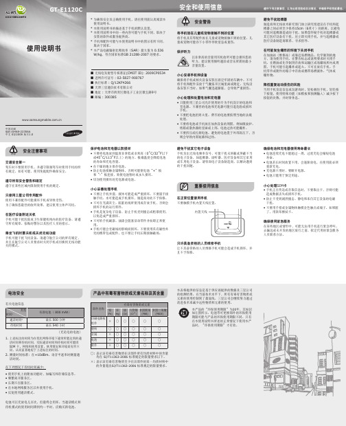
手机部位图
1 2 3 4
1
5
手机在屏幕最上一行显示下列状态指示图标:
四向导航键 在待机模式下,进入到用户自
用。 • 手机可能会受磁场的影响而损坏。不要使用具有磁性外
壳的携带包或配件,也不要让手机长期接触磁场。
避免干扰其它电子设备 手机发出无线电频率信号,可能干扰未屏蔽或屏蔽不当 的电子设备,如起搏器、助听器、医疗设备和其它家用 或车用电子设备。请咨询电子设备制造商,以解决遇到 的干扰问题。
重要使用信息
在正常位置使用手机 不要触摸手机内置天线位置。
中国印刷 编码:GH68-22356A 中文 03/2009 版本1.0
安全和使用信息
遵守下列注意事项,以免出现危险或非法情况,并确保手机性能最佳。
安全警告
警告
将手机放在儿童或宠物接触不到的位置 将手机及其零配件放在儿童或宠物接触不到的位置。儿 童或宠物可能吞下小零件导致窒息或重伤。
保护听力 以非常高的音量用耳机收听可能会损坏您的 听力。建议使用倾听通话或音乐所需的最小 音量设置。
降低重复运动损伤的风险 当用手机发送信息或玩游戏时,轻松握住手机,轻轻按 下按钮,使用特殊功能(如模板和预测输入)减少按下 按钮的次数,并时常休息。
安全注意事项
小心
交通安全第一 驾车时不要使用手机,并遵守限制驾车时使用手机的所 有规定。如有可能,使用免提配件确保安全。
遵守所有安全警告和规定 遵守在某些区域内限制使用手机的规定。
产品中有毒有害物质或元素名称及其含量
FQA11N90C中文资料

(Note 4)(Note 4, 5)(Note 4, 5) (Note 4)Notes:1. Repetitive Rating : Pulse width limited by maximum junction temperature2. L = 15mH, I AS = 11.0A, V DD = 50V, R G = 25 Ω, Starting T J = 25°C3. I SD ≤11.0A, di/dt ≤ 200A/µs, V DD ≤ BV DSS, Starting T J = 25°C4. Pulse Test : Pulse width ≤300µs, Duty cycle ≤2%5. Essentially independent of operating temperature∆BV DSS / ∆T J Breakdown Voltage Temperature CoefficientI D = 250 µA, Referenced to 25°C -- 1.02--V/°C I DSS Zero Gate Voltage Drain Current V DS = 900 V, V GS = 0 V ----10µA V DS = 720 V, T C = 125°C ----100µA I GSSF Gate-Body Leakage Current, Forward V GS = 30 V, V DS = 0 V ----100nA I GSSRGate-Body Leakage Current, ReverseV GS = -30 V, V DS = 0 V-----100nAOn CharacteristicsV GS(th)Gate Threshold Voltage V DS = V GS , I D = 250 µA3.0-- 5.0V R DS(on)Static Drain-Source On-ResistanceV GS = 10 V, I D = 5.5 A --0.911.1Ωg FSForward TransconductanceV DS = 50 V, I D = 5.5 A ----SDynamic CharacteristicsC iss Input Capacitance V DS = 25 V, V GS = 0 V, f = 1.0 MHz--25303290pF C oss Output Capacitance--215280pF C rssReverse Transfer Capacitance--2330pFSwitching Characteristicst d(on)Turn-On Delay Time V DD = 450 V, I D = 11.0 A,R G = 25 Ω--60130ns t r Turn-On Rise Time --130270ns t d(off)Turn-Off Delay Time --130270ns t f Turn-Off Fall Time --85180ns Q g Total Gate Charge V DS = 720 V, I D = 11.0 A,V GS = 10 V--6080nC Q gs Gate-Source Charge --13--nC Q gdGate-Drain Charge--25--nCDrain-Source Diode Characteristics and Maximum RatingsI S Maximum Continuous Drain-Source Diode Forward Current ----11.0A I SM Maximum Pulsed Drain-Source Diode Forward Current----44.0A V SD Drain-Source Diode Forward Voltage V GS = 0 V, I S = 11.0 A ---- 1.4V t rr Reverse Recovery Time V GS = 0 V, I S = 11.0 A,dI F / dt = 100 A/µs--1000--ns Q rrReverse Recovery Charge--17.0--µCDISCLAIMERFAIRCHILD SEMICONDUCTOR RESERVES THE RIGHT TO MAKE CHANGES WITHOUT FURTHER NOTICE TO ANY PRODUCTS HEREIN TO IMPROVE RELIABILITY, FUNCTION OR DESIGN. FAIRCHILD DOES NOT ASSUME ANY LIABILITY ARISING OUT OF THE APPLICATION OR USE OF ANY PRODUCT OR CIRCUIT DESCRIBED HEREIN;NEITHER DOES IT CONVEY ANY LICENSE UNDER ITS PATENT RIGHTS, NOR THE RIGHTS OF OTHERS.LIFE SUPPORT POLICYFAIRCHILD’S PRODUCTS ARE NOT AUTHORIZED FOR USE AS CRITICAL COMPONENTS IN LIFE SUPPORT DEVICES OR SYSTEMS WITHOUT THE EXPRESS WRITTEN APPROVAL OF FAIRCHILD SEMICONDUCTOR CORPORATION.As used herein:1. Life support devices or systems are devices or systems which, (a) are intended for surgical implant into the body,or (b) support or sustain life, or (c) whose failure to perform when properly used in accordance with instructions for use provided in the labeling, can be reasonably expected to result in significant injury to the user.2. A critical component is any component of a life support device or system whose failure to perform can be reasonably expected to cause the failure of the life support device or system, or to affect its safety or effectiveness.PRODUCT STATUS DEFINITIONS Definition of TermsDatasheet Identification Product Status DefinitionAdvance InformationFormative or In Design This datasheet contains the design specifications for product development. Specifications may change in any manner without notice.PreliminaryFirst ProductionThis datasheet contains preliminary data, andsupplementary data will be published at a later date.Fairchild Semiconductor reserves the right to make changes at any time without notice in order to improve design.No Identification Needed Full ProductionThis datasheet contains final specifications. Fairchild Semiconductor reserves the right to make changes at any time without notice in order to improve design.Obsolete Not In ProductionThis datasheet contains specifications on a product that has been discontinued by Fairchild semiconductor.The datasheet is printed for reference information only.TRADEMARKSThe following are registered and unregistered trademarks Fairchild Semiconductor owns or is authorized to use and is not intended to be an exhaustive list of all such trademarks.FACT™FACT Quiet series™FAST ®FASTr™FRFET™GlobalOptoisolator™GTO™HiSeC™I 2C™ImpliedDisconnect™ISOPLANAR™LittleFET™MicroFET™MicroPak™MICROWIRE™MSX™MSXPro™OCX™OCXPro™OPTOLOGIC ®OPTOPLANAR™PACMAN™POP™Power247™PowerTrench ®QFET™QS™QT Optoelectronics™Quiet Series™RapidConfigure™RapidConnect™SILENT SWITCHER ®SMART START™SPM™Stealth™SuperSOT™-3SuperSOT™-6SuperSOT™-8SyncFET™TinyLogic™TruTranslation™UHC™UltraFET ®VCX™ACEx™ActiveArray™Bottomless™CoolFET™CROSSVOLT ™DOME™EcoSPARK™E 2CMOS™EnSigna™Across the board. Around the world.™The Power Franchise™Programmable Active Droop™。
unoconv参数

unoconv参数
unoconv是一个用于在不同文档格式之间进行转换的命令行工具。
它可以将文档从一种格式转换为另一种格式,比如将Microsoft Word文档转换为PDF,或者将ODF(Open Document Format)文档转换为HTML。
unoconv的参数非常丰富,下面我会列举一些常用的参数及其作用:
1. -f, --format,指定输出文件的格式,比如使用-f pdf可以将文档转换为PDF格式。
2. -e, --export,指定要使用的过滤器,比如使用-e PageRange=1-3可以指定转换的页面范围。
3. -d, --doctype,指定输入文档的类型,比如使用-d spreadsheet可以指定输入文档为电子表格。
4. -i, --import,指定要使用的过滤器来打开文档,比如使用-i Text可以指定使用文本过滤器打开文档。
5. -n, --no-launch,在转换文档时不启动LibreOffice或
OpenOffice。
6. -v, --verbose,输出详细的日志信息,用于调试和排查问题。
除了上述参数外,unoconv还有许多其他参数,用于处理不同类型的文档和实现特定的转换需求。
在使用unoconv时,可以通过--help参数来查看完整的参数列表和其用法说明,以便根据实际需求来选择合适的参数进行文档转换。
希望这些信息能够帮助你更好地了解unoconv的参数用法。
N9038A MXE EMI接收器数据手册说明书

1981N9038A MXE EMI Receiver20 Hz to 8.4 and 26.5 GHzData SheetTable of ContentsDefinitions and Conditions (3)Frequency and Time Specifications (4)Amplitude Accuracy and Range Specifications (7)Dynamic Range Specifications (10)PowerSuite Measurement Specifications (15)General Specifications (16)Inputs and Outputs (18)I/Q Analyzer .....................................................................................................................20 Express your insight When you’re testing a new prod-uct, the designers are counting on your expertise and advice. That’s why the Agilent MXE is more than a CISPR-compliant EMI receiver. We’ve also included X-Series signal analysis and graphical measure-ment tools that make it easy to examine signal details. With these diagnostic capabilities, the MXE complements your knowledge and helps you advise the designers if a device fails compliance testing. Equip your lab with the MXE—and express your insight.2Definitions and Conditions Specifications describe the performance of parameters covered by the productwarranty and apply to the full temperature range of 0 to 55 °C, unless otherwise noted.95th percentile values indicate the breadth of the population (approx. 2 σ) of performance tolerances expected to be met in 95 percent of the cases with a 95 percent confidence, for any ambient temperature in the range of 20 to 30 °C. In addition to the statistical observations of a sample of instruments, these values include the effects of the uncertainties of external calibration references. These values are not warranted. These values are updated occasionally ifa significant change in the statistically observed behavior of production instruments is observed.Typical describes additional product performance information that is not covered by the product warranty. It is performance beyond specifications that 80 percent of the units exhibit with a 95 percent confidence level over the temperature range 20 to 30 °C. Typical performance does not include measurement uncertainty. Nominal values indicate expected performance, or describe product performance that is useful in the application of the product, but are not covered by the product warranty.The receiver will meet its specifications when:• It is within its calibration cycle• Under auto couple control, except when Auto Sweep Time Rules = Accy • Signal frequencies < 10 MHz, with DC coupling applied• The receiver has been stored at an ambient temperature within the allowed operating range for at least two hours before being turned on• The receiver has been turned on at least 30 minutes with Auto Align set to normal, or, if Auto Align is set to off or partial, alignments must have been run recently enough to prevent an Alert message; if the Alert condition is changed from “Time and Temperature” to one of the disabled duration choices, the receiver may fail to meet specifications without informing the user This data sheet is a summary of the complete specifications and condi-tions, which are available in the MXE EMI Receiver Specification Guide. The MXE EMI Receiver Specification Guide can be obtained on the Web at: /find/mxe_specifications For ordering information, refer to the MXE EMI Receiver Configuration Guide (5990-7419EN).3Frequency and Time Specifications1. Horizontal resolution is span/(sweep points – 1).4561. Analysis bandwidth is the instantaneous bandwidth available around a center frequency over which the input signal can be digitized for further analysis or processing in the time, frequency, or modulation domain.2. Sweep points = 101.Amplitude Accuracy and Range Specifications1. DC coupling required to meet specifications below 50 MHz. With AC coupling, specifications apply at frequencies of 50 MHz and higher. Statisticalobservations at 10 MHz with AC coupling show that most instruments meet the DC-coupled specifications, however, a small percentage of instrumentsare expected to have errors exceeding 0.5 dB at 10 MHz at the temperature extreme. The effect at 20 to 50 MHz is negligible but not warranted.781. DC coupling required to meet specifications below 50 MHz. With AC coupling, specifications apply at frequencies of 50 MHz and higher. Statisticalobservations at 10 MHz with AC coupling show that most instruments meet the DC-coupled specifications, however, a small percentage of instruments are expected to have errors exceeding 0.5 dB at 10 MHz at the temperature extreme. The effect at 20 to 50 MHz is negligible but not warranted.9Dynamic Range Specifications1. Typical DANL including NFE = Typical DANL-DANL improvement with NFE2. Specified for instruments with prefixes MY/SG5213 or greater. Nominal for instruments with earlier prefixes.101. Typical DANL including NFE = Typical DANL-DANL improvement with NFE.2. No NFE factor at this frequency.3. Specified for instruments with prefixes MY/SG5213 or greater. Nominal for instruments with earlier prefixes.1. Typical Indicated Noise including NFE = Typical DANL+ Bandwidth and Log corrrections-DANL improvement with NFE2. No NFE factor at this frequency.3. Specified for instruments with prefixes MY/SG5213 or greater. Nominal for instruments with earlier prefixes.1. Preamp input power = input power-input attenuation (–9 dB for input 2).2. For nominal values, refer to Figure 1.Figure 1. Nominal phase noise at different center frequenciesPowerSuite Measurement SpecificationsGeneral Specifications1. Noise Floor Extension (NFE) required for isolated pulse in bands C and D only.Inputs and OutputsI/Q Analyzer /find/mxe For more information on Agilent Tech-nologies’ products, applications or services, please contact your local Agilent office. The complete list is available at:/find/contactus Americas Canada (877) 894 4414 Brazil (11) 4197 3600Mexico 01800 5064 800 United States (800) 829 4444 Asia Pacific Australia 1 800 629 485China 800 810 0189Hong Kong 800 938 693India 1 800 112 929Japan 0120 (421) 345Korea 080 769 0800Malaysia 1 800 888 848Singapore 180****8100Taiwan 0800 047 866Other AP Countries (65) 375 8100 Europe & Middle East Belgium 32 (0) 2 404 93 40Denmark 45 45 80 12 15Finland 358 (0) 10 855 2100France 0825 010 700* *0.125 €/minute Germany 49 (0) 7031 464 6333 Ireland 1890 924 204I srael 972-3-9288-504/544Italy 39 02 92 60 8484Netherlands 31 (0) 20 547 2111Spain 34 (91) 631 3300Sweden 0200-88 22 55United Kingdom 44 (0) 118 927 6201For other unlisted countries: /find/contactus Revised: January 6, 2012Product specifications and descriptions in this document subject to change without notice.© Agilent Technologies, Inc. 2012Published in USA, July 26, 20125990-7421EN Agilent Advantage Services is committed to your success throughout your equip-ment’s lifetime. To keep you competitive, we continually invest in tools and processes that speed up calibration and repair and reduce your cost of ownership. You can also use Infoline Web Services to manage equipment and services more effectively. By sharing our measurement and service expertise, we help you create the products that change our /quality /find/advantageservices /find/emailupdates Get the latest information on the products and applications you select. LAN eXtensions for Instruments puts the power of Ethernet and the Web inside your test systems. Agilent is a founding member of the LXI consor-tium.Agilent Channel Partnersw w w /find/channelpartners Get the best of both worlds: Agilent’s measurement expertise and product breadth, combined with channel partner convenience.。
腾达无线路由设置使用说明书
版 权 申 明是深圳市吉祥腾达科技有限公司注册商标。
文中提及到的其它商标或商品名称均是他们所属公司的商标或注册商标。
本产品的所有部分,包括配件和软件,其版权属深圳市吉祥腾达科技有限公司所有,在未经过深圳市吉祥腾达科技有限公司许可的情况下,不得任意拷贝、抄袭、仿制或翻译成其它语言。
本手册中的所有图片和产品规格参数仅供参考,随着软件或硬件的升级会略有差异,如有变更,恕不另行通知,如需了解更多产品信息,请浏览我们的网站:目录第1章产品简介 (4)1.1包装清单 (4)1.2面板指示灯及接口说明 (4)第2章产品安装 (6)第3章如何设置上网 (7)3.1正确设置您的计算机网络配置 (7)3.2登录路由器 (12)3.3快速上网 (12)3.4快速加密 (13)第4章高级设置 (14)4.1系统状态 (14)4.2WAN设置 (15)4.3LAN口设置 (18)4.4DNS设置 (19)4.5WAN介质类型 (20)4.6带宽控制 (21)4.7流量统计 (23)第5章无线设置 (24)5.1无线基本设置 (24)5.2无线安全设置 (28)5.3无线访问控制 (29)5.4连接状态 (31)第6章 DHCP服务器 (32)6.1DHCP服务设置 (32)6.2DHCP客户列表 (32)第7章虚拟服务器 (34)7.1端口段映射 (34)7.2DMZ主机 (35)7.3UPNP设置 (36)第8章安全设置 (37)8.1客户端过滤 (37)8.2MAC地址过滤 (38)8.3URL过滤 (39)8.4远程WEB管理 (41)第9章路由设置 (42)9.1路由列表 (42)9.2静态路由 (42)第10章系统工具 (43)10.1时间设置 (43)10.2DDNS (43)10.3备份/恢复设置 (44)10.4恢复出厂设置 (45)10.5升级 (46)10.6重启路由器 (46)10.7修改密码 (46)10.8系统日志 (47)10.9退出登录 (47)附录一:常用无线名词解释 (48)附录二:产品特性 (50)附录三:常见问题解答 (51)附录四:清除无线配置文件 (53)附录五:产品有毒有害物质清单 (55)第1章产品简介感谢您购买腾达 11N无线宽带路由器(以下简称路由器)。
fc11a电动执行器说明书
fc11a电动执行器说明书阀门电动执行器使用说明:阀门电动执行器在使用的时候,必须按照正规的使用,如果不懂随便乱操作,则会导致阀门产生危害。
则建议大家在使用的时候,经过专业培训在使用,这样对我们来说比较有利。
那么这机器该怎么维护呢?1.我们看到它维护的方式是需要长期进行的,不是短期进行。
在使用了该机器之后,应当检查下机器有没有受到损坏。
2.如果机器受到损坏,则就会影响我们使用,而大家应当要做的则是,在发现问题之后及时的检修,这样才能够避免出现更多的故障。
这里简单来说下它的维护方式,在维护的时候,首先注意使用方式,及我们的电压是不是正常。
1.阀门电动执行器对电压也有一定的要求,如果电压不够,会损坏到机器,则注意检查电压,防止机器产生一定的危害,这点一定要注意。
2.在电压不够带动机器的情况下,千万不要去随意的使用,这对于我们来说是很不利的。
3.还有,应当检查机器是不是有噪音,或者电子元件是不是过日。
如果发现这两方面的问题.则要及时性的进行检查,千万不要不放在心上。
原因很简单,因为小问题往往会带动大毛病,我们要做的则是及时的检查,及时的进行维修。
这样,及时注意阀门电动执行器所产生的任何动态,一旦有故障及时给与维修,就不会出现问题了。
阀门电动执行器故障处理方法:一.电动执行器电机起不动原因: 1.电源线脱开,,2.控制线路故障3.行程与力矩控制机构失灵。
排除方法:1.检查电源线,2.排除线路故障,3.排除行程或力矩控制机构故障。
二.输出轴旋向不符合规定原因:电源相序接反。
排除方法:调换任意两电源线。
三.电机过热原因:1.连续工作时间太长,2.一相线断开。
排除方法:1.停止运行,使电机冷却,2.检查电源线。
四.运行中的电机停转原因:1.阀门有故障,2.电动装置过载,力矩控制机构动作。
排除方法:1.检查阀门,2.增大整定转矩。
五.电动阀门到位后电机不停转或灯不亮原因:1.行程或力矩控制机构有故障,2.行程控制机构调整不当。
N900 (WNCE4004) 4门网络适配器指南说明书

Guida all'installazioneAdattatore WiFi 4 porte per video e gioco N900(WNCE4004)AlimentatoreCavo EthernetWNCE4004LED di link WPS LED Tasto WPSPorte EthernetPresa dialimentazioneInstallazione con WPSFase 2:attendere che il LED di link sulWNCE4004 lampeggi di colore verde. Premere il tasto WPS sul WNCE4004. Il LED WPS lampeggia di colore blu per indicare l'esecuzione di WPS.Fase 3:premere il tasto WPS sul router. Quando la connessionewireless è stata stabilita, il LED di link cambia colore per indicare la qualità della connessione: verde senza intermittenza, giallo senza intermittenza o rosso senza intermittenza. Vedere Attività del LED di link su lato opposto di questo documento per ulteriori informazioni sul significato di questi colori.Fase 1:Collegare WNCE4004 alla TV , XBoxo al lettore Blu-ray utilizzando il cavo Ethernet (fornito in dotazione) e l'alimentatore.Fase 4:complimenti! L'installazione è stata completata consuccesso.Cosa significa WPS?Se si è in possesso di un router NETGEAR, questa funzionalità è nota come Push ‘N’ Connect. Cercare i simboli o sul router per assicurarsi che il router NETGEAR supporti la funzionalità WPS. In caso di router non NETGEAR, consultare il manuale utente per sapere se la funzionalità WPS è supportata.Una volta accertato se il router supporta o meno la funzionalità WPS, scegliere il metodo di installazione più indicato.WPS significa "WiFi Protected Setup" ed è una procedura che consente di collegare un dispositivo a una rete esistente in maniera semplice e sicura.Installazione senza WPSTasto WPSTasto WPSFase 1: Installare WNCE4004 sul computer, scollegare la relativa connessionewireless al router e/o rimuovere l'eventuale cavo Ethernet collegato al computer. È possibile ripristinare la connessione dopo aver completato l'installazione di WNCE4004.Fase 2:Collegare WNCE4004 al computer utilizzando il cavo Ethernet (fornito in dotazione) e poi l'alimentatore.Fase 3: Attendere che il LED di link lampeggi di colore verde. Verificare checomputer disponga dell'indirizzo IP. Quindi aprire il browser Internet, il quale aprirà automaticamente la pagina di configurazione (se questo non succede, digitare manualmente nel browser l'indirizzo.) Il nome utente predefinito è admin e la password predefinita è password . Attenersi alle istruzioni contenute nella pagina per la configurazione, quindi tornare al manuale e continuare dalla Fase 4.Fase 4:Scollegare i cavi Ethernet e USB dal computer.Fase 5:Collegare WNCE4004 alla TV , XBox o al lettore Blu-ray.Fase 6:Complimenti! L'installazione è stata completata con successo.NOTA : accertarsi di verificare le impostazioni di connessione di TV , XBox o lettore Blu-ray dopo aver configurato e connesso WNCE4004. Se richiesto per il tipo di connessione, accertarsi di aver selezionato Wired (cablata).Luglio 2012Questo simbolo indica la conformità alla direttiva dell'Unione Europea 2002/96 sullo smaltimentodegli apparecchi elettrici ed elettronici (direttiva RAEE). In caso di smaltimento in Paesidell'Unione Europea, questo prodotto deve essere smaltito e riciclato nel rispetto delle leggi localiche applicano la direttiva RAEE.NETGEAR, il logo NETGEAR e Connect with Innovation sono marchi commerciali e/o marchi registrati di NETGEAR, Inc. e/o delle sue consociate negli Stati Uniti e/o in altri Paesi. Le informazioni sono soggette a modifica senza preavviso. Altri nomi di prodotti e marche sono marchi registrati o marchi commerciali dei rispettivi proprietari. © NETGEAR, Inc. Tutti i diritti riservati.Solo per utilizzo all''interno in tutti i paesi dell'UE e in Svizzera.Procedura WPSQuando si preme il pulsante WPS per stabilire una connessione wireless, si verifica la sequenza di eventi seguente:1. Quando la procedura WPS è in corso, il LED WPS lampeggia di colore blu per 0,5secondi e quindi si spegne per 0,5 secondi, continuamente.2. Quando viene correttamente effettuata un'associazione di sicurezza in un AP (accesspoint) radice, il LED WPS si accende di colore blu. Se viene effettuataun'associazione senza sicurezza, il LED WPS si spegne.3. Una volta completata la procedura WPS, sul LED del link viene visualizzatal'informazione relativa alla qualità della velocità di connessione: verde senzaintermittenza, giallo senza intermittenza o rosso senza intermittenza.Nota: Se c'è un errore di WPS, il LED WPS lampeggia continuativamente nella seguente modalità: tre lampeggiamenti lenti e interruzione del lampeggiamento per un tempo che va da 1 a 1,5 secondi.Domande frequenti1. Durante la configurazione di WNCE4004 senza WPS, è necessario che il computersia impostato su DHCP per la buona riuscita dell'installazione?Sì.2. Perché viene visualizzato l'errore “Connection was not established to the selectednetwork” ("La connessione alla rete selezionata non è stata stabilita.")?Le ragioni di un errore di connessione possono essere molteplici. Prima di tutto, èpossibile che siano stati inseriti un nome o una chiave di rete incorretti. Assicurarsi diaver inserito i dati in maniera corretta facendo clic su Cancel (Annulla) e digitandonuovamente nome e chiave di rete. In secondo luogo, è possibile che il router abbiainterrotto la trasmissione del segnale wireless. Assicurarsi che il router sia acceso eche ci sia una chiara linea di visione tra WNCE4004 e il router. Se possibile,avvicinare WNCE4004 al router e fare clic su Try Again (Riprova). Se il messaggiodi errore continua ad apparire anche dopo diversi tentativi di riconnessione, potrebbeessere necessario aggiornare il router oppure acquistare un Range Extender peraumentare la copertura del segnale.3. Ho cercato di installare il prodotto senza WPS ma, al lancio del browser, è apparso unerrore. Come risolvere il problema?Assicurarsi che il cavo Ethernet sia ben collegato a WNCE4004 e al computer e che ilLED di link sul dispositivo a cui è collegato il WNCE4004 sia acceso. Se il LEd dilink non è acceso, ricollegare il cavo Ethernet e avviare di nuovo il browser Internet.4. Di che colore si illumina il LED di link per indicare la corretta configurazione diWNCE4004?Il LED di link sul WNCE4004 lampeggia di colore verde quando non è connesso adalcun access point. Una volta stabilita la connessione wireless, il LED di linkdovrebbe restare verde senza intermittenza, giallo senza intermittenza o rosso senzaintermittenza in base alla qualità del collegamento wireless.5. Cosa fare nel caso in cui il LED di link sia rosso?La migliore connessione si stabilisce quando è presente una linea di visione chiara traWNCE4004 e il router a cui ci si connette. Assicurarsi che non ci siano ostacoli fisicitra WNCE4004 e il router. Si consiglia inoltre di avvicinare WNCE4004 quanto piùpossibile al router.6. Come posso cambiare le impostazioni dopo aver configurato WNCE4004 la primavolta?Seguire le istruzioni riportate nella sezione Installazione senza WPS. Collegarsi allapagina per configurare le impostazioni avanzate.Attività del LED di linkPer la documentazione completa, visitare il sito Web relativo alla Dichiarazione diconformità EU di NETGEAR all'indirizzo:/app/answers/detail/a_id/11621Una volta completata l'installazione, registrare il dispositivo all'indirizzo:/register per poter utilizzare il servizio di assistenza telefonica.Visitare anche il sito Web per ottenere aggiornamenti sulprodotto, ulteriore documentazione e assistenza.Scaricare il manuale utente all'indirizzo o attraverso illink presente nell'interfaccia utente del prodotto.Attività del LEDSpento L'unità non è alimentata.Rosso fisso La qualità del collegamento è scarsa, in base alla velocità diconnessione.RossolampeggianteSe il LED lampeggia di rosso con intervalli acceso/spentociascuno di 0,5 secondi, il firmware è corrotto. Per leistruzioni, fare riferimento al manuale utente.Giallo fisso La qualità del collegamento è sufficiente, in base alla velocitàdi connessione.RossolampeggianteÈ in corso il riavvio del sistema o il sistema è stato ripristinato.Dopo aver premuto il pulsante di ripristino per più di cinquesecondi, il LED è rosso lampeggiante. Il LED lampeggia dicolore rosso anche durante l'aggiornamento di un firmware.Verde fisso L'unità è accesa e la qualità del collegamento è buona, inbase alla velocità di connessione.VerdelampeggianteL'avvio è terminato, ma non è stata stabilita alcunaconnessione wireless, pertanto l'indirizzo IP non è disponibile.。
11n无线标准
11n无线标准11n无线标准,又称为IEEE 802.11n,是一种无线局域网技术标准,它是对802.11a/b/g标准的扩展和改进。
与之前的标准相比,11n无线标准在速度、覆盖范围和信号稳定性等方面都有了显著的提升,成为了当前主流的无线网络技术之一。
本文将对11n无线标准的技术特点、优势和应用进行介绍。
首先,11n无线标准采用了MIMO技术(Multiple-Input Multiple-Output),即多输入多输出技术。
通过利用多个天线进行数据传输和接收,MIMO技术可以显著提高无线网络的数据传输速度和稳定性。
同时,MIMO技术还可以有效地抵抗多径效应和信号衰减,提高了无线网络的覆盖范围和抗干扰能力。
其次,11n无线标准采用了40MHz的信道带宽,相较于之前的20MHz带宽,可以提供更大的数据传输通道,从而进一步提高了无线网络的传输速度。
此外,11n标准还引入了空间复用技术,通过同时传输多个数据流,进一步提高了网络的数据传输效率。
除此之外,11n无线标准还支持动态信道绑定和自适应调制编码技术,可以根据网络环境的变化自动调整信道和编码方式,以最大限度地提高数据传输的稳定性和速度。
同时,11n标准还支持绿色无线技术,通过动态调整传输功率和休眠模式,有效降低了无线网络设备的能耗,减少了对环境的影响。
在实际应用中,11n无线标准已经被广泛应用于家庭无线网络、企业无线局域网、公共场所无线覆盖等领域。
由于其高速、稳定、覆盖范围广等优势,11n无线网络已经成为了大多数用户的首选。
在未来,随着物联网、5G等新技术的发展,11n无线标准仍将发挥重要作用,为人们的日常生活和工作提供更加便捷的无线连接。
总之,11n无线标准作为一种先进的无线网络技术,具有高速、稳定、覆盖范围广等优势,已经成为了当前主流的无线网络技术之一。
随着技术的不断发展和应用的不断普及,相信11n无线标准将会在未来发挥越来越重要的作用,为人们的生活和工作带来更多便利和可能。
A1E 系列交流伺服驱动器 用户手册说明书

基本规格 ........................................................................................................................................... 4
速度、位置、转矩控制规格 ........................................................................................................... 5
1
1.1
1.2
1.3
1.4
1.5
2
2.1
2.2
2.2.1
2.2.2
2.3
2.4
2.5
3
3.1
3.2
3.3
4
4.1
4.2
4.3
4.4
4.5
4.5.1
4.5.2
4.5.3
5
安全提醒 ................................................................................................................................................... 1
JFC-11说明书

一、简介10AC过滤器控制装置是特别为盘式过滤器反洗控制而专门设计的,该装置由专门开发的电子控制器和机电一体的分配器共同组成。
在使用中具有非常优越的特点:1.方便的工作电源100-250V/AC,不必担心因电压波动而无法正常工作;2.精确显示系统将要启动反冲洗程序的剩余时间或压差信号状态;3.反洗启动方式的多样化:隔时启动、远端或压差信号启动、人工强制启动;4.输入输出信号的多元化:压差或远端信号输入、反洗分配器、主阀信号输出、延时阀信号输出、声音报警及报警信号输出;5.多种重要信息记录:压差表开关信号启动次数、隔时启动次数、人工强制启动次数、以及系统运行总时间的累计记录;6.方便的操作方式,可以轻松改变参数的设置。
7.直观的反洗过程灯光显示:在进行反洗的过程中,控制器右侧的灯光将形象的进行显示,第一个主阀由红色二极管发光表示关闭,其余绿色二极管表示相对应的反洗阀和延时阀的动作状态,绿灯常亮,表示延时阀已经打开,绿灯闪烁,表示反洗阀已经打开。
二、安装控制器的安装过程包括以下几个步骤:1.分配器的连接(反洗单元为3—11之间任意选择,此项为必选项)。
2.主阀的连接(此项既可以选择分配器控制,也可以选择电气控制,也可以不选择主阀,为可选项)。
3.延时阀的连接(如果需要延时阀,则延时阀必须由控制器进行电气控制,也可以不选择延时阀,此项为可选项)。
4.压差信号的连接(压差信号来自于进出水压差表的接点信号,如果不选择压差表,也可以采用时间参数进行控制,此项为可选项)。
5.其他输入输出信号的连接(如果反洗全过程需要远传,或者需要远端控制反洗程序启动,则可以通过相关接点连接得到实施,此项为可选项)。
6.电源的连接(220V/AC,单相,50/60Hz)。
三、10AC控制器键盘的功能:><为左右移动键、∧∨键为参数设置键、ENTER为参数确认键四、参数的设置设备接通工作电源后,可以看到屏幕有下列显示:在以上画面中,表示系统反冲洗采用的是压差信号启动,距离上次系统反冲洗已经运行了25分钟,而此时还表示压差表还没有发出反洗信号。
EDFA11FPC 和 EDFB12FPC 冻结抵抗字体的产品说明书
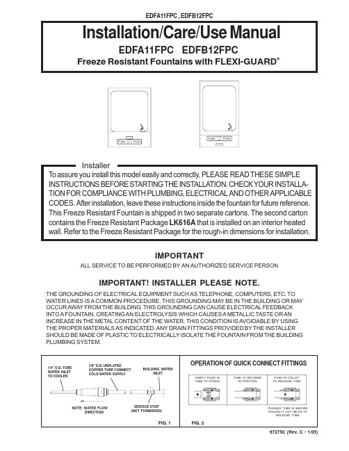
97275C (Rev. C - 1/05)Installation/Care/Use ManualEDFA11FPC EDFB12FPCFreeze Resistant Fountains with FLEXI-GUARD ®IMPORTANT! INSTALLER PLEASE NOTE.THE GROUNDING OF ELECTRICAL EQUIPMENT SUCH AS TELEPHONE, COMPUTERS, ETC. TO WATER LINES IS A COMMON PROCEDURE. THIS GROUNDING MAY BE IN THE BUILDING OR MAY OCCUR AWAY FROM THE BUILDING . THIS GROUNDING CAN CAUSE ELECTRICAL FEEDBACK INTO A FOUNTAIN, CREATING AN ELECTROLYSIS WHICH CAUSES A METALLIC TASTE OR AN INCREASE IN THE METAL CONTENT OF THE WATER. THIS CONDITION IS AVOIDABLE BY USING THE PROPER MATERIALS AS INDICATED. ANY DRAIN FITTINGS PROVIDED BY THE INSTALLER SHOULD BE MADE OF PLASTIC TO ELECTRICALLY ISOLATE THE FOUNTAIN FROM THE BUILDING PLUMBING SYSTEM.IMPORTANTALL SERVICE TO BE PERFORMED BY AN AUTHORIZED SERVICE PERSONFIG. 1NOTE: WA TER FLOW DIRECTIONBUILDING WA TER INLETSERVICE STOP (NOT FURNISHED)1/4" O.D. TUBE WA TER INLET TO COOLER3/8" O.D. UNPLATEDCOPPER TUBE CONNECT COLD WA TER SUPPLYTUBE IS SECUREDIN POSITIONSIMPLY PUSH IN TUBE TO ATTACHPUSH IN COLLET TO RELEASE TUBEPUSHING TUBE IN BEFORE PULLING IT OUT HELPS TORELEASE TUBEFIG. 2OPERATION OF QUICK CONNECT FITTINGS97275C (Rev. C - 1/05)FIG. 3PAGE 2EDFA11FPC INSTALLATION INSTRUCTIONS1. Wall should already be framed for the fountain using dimensions shown in Fig. 3.Shown dimensions pertain to installation location. These dimensions are required for compliance withANSI Standard A117.1. and ADA.2. Rough-in wall that freeze resistant box is to be attached to - see box instructions.3. Attach the hanger bracket to the wall as shown in Fig. 3 . Use bolts and flat washers (not provided).Tighten securely.4. Cut drain tube (supplied with freeze resistant box). Length of tube is measured from centerline of thefountain drain to the end of the tube. Cut length is to be 1" (25mm) less than the wall thickness.5. Attach push rod (supplied with freeze resistant box) to push bar assy (item 6) with screw & clip(items 5 & 12). See Fig. 6.6. Install fountain by aligning drain tube and push rod with holes in freeze resistant box while hanging thefountain on the hanger bracket. Attach fountain to wall with screws (not provided).7. Install freeze resistant box and connect fountain water line to freeze resistant box - see box instructions. Install bottom cover.8. Install a service stop (not provided) and make water supply connection from the stop to the strainer in the freeze resistant box. DO NOT SOLDER TUBES INSERTED INTO THE STRAINER AS DAMAGE TO THE O-RINGS MAY RESULT.*NOTE: All dimensions are taken from the finished floor on the side of the wall that the fountain is installed on.EDFA11FPC ROUGH-IN97275C (Rev. C - 1/05)PAGE 3FIG. 4EDFB12FPC ROUGH-INEDFB12FPC INSTALLATION INSTRUCTIONS1. Wall should already be framed for the fountain using dimensions shown in Fig. 4.Shown dimensions pertain to installation location. These dimensions are required for compliance with ANSI Standard A117.1. and ADA.2. Rough-in wall that freeze resistant box is to be attached to - see box instructions.3. Attach the hanger bracket to the wall as shown in Fig. 4 . Use bolts and flat washers (not provided). Tighten securely.4. Cut drain tube (supplied with freeze resistant box). Length of tube is measured from centerline of the fountain drain to the end of the tube. Cut length is to be 6-3/16" (157mm) less than the wall thickness.5. Attach push rod (supplied with freeze resistant box) to push bar assy (item 6) with screw & clip (items 5 & 12). See Fig.6.6. Install fountain by aligning drain tube and push rod with holes in freeze resistant box while hanging the fountain on the hanger bracket. Attach fountain to wall with screws (not provided).7. Install freeze resistant box and connect fountain water line to freeze resistant box - see box instructions. Install bottom cover.8. Install a service stop (not provided) and make water supply connection from the stop to the strainer in the freeze resistant box.DO NOT SOLDER TUBES INSERTED INTO THE STRAINER AS DAMAGE TO THE O-RINGS MAY RESULT.*NOTE: All dimensions are taken from the finished floor on the side of the wall that the fountain is installed on.97275C (Rev. C - 1/05)PAGE 4DESCRIPTIONCP11550010865500109722912C 21705C 21708C 40322C 55997C 50198C 56011C 56073C 70002C 75580C 70018C 70278C 75555C 70683C 28579C12345678910111213141516NS NSP ART NO.COVER PLATEFOUNTAIN BODY (EDFB12FPC)FOUNTAIN BODY (EDFA11FPC)BRACKET-PUSH BAR MTG CLIP-PUSH RODPUSH BAR ASSY-BUFFED ORIFICE ASSY PEDESTALBSHNG-SNAP .125ID HOUSING ASSEMBLY BUBBLER ASSYSCREW-#10 X .50 HHSM NUT-3/8-18 LKNT NUT-HEX 1/4-20ROD-SUPPORTCLIP-.125 STUD LOCK UNION - 1/4WALL HANGER BRACKETITEM NO.PARTS LIST8111071349121551412FIG. 5FIG. 6166SEE FIG. 51SEE FIG. 623SEE FIG. 5SEE FIG. 6 800-518-5388。
通用变频器说明书

停止频率
停车模式
转向切换等待时 间 待机时间 停机直流制动时 间 停机直流制动电 压 启动直流制动时 间 启动直流制动电 压 跳跃频率宽度 第一跳跃频率
0.0~400.0Hz 0:自由停车 1:减速停车 0~1000s
0~1000s 0~100.0s
0~100V
0~100.0s
0~100V 0.0~100.0Hz 0.0~4000.0Hz
0.0~4000.0Hz
F0.05 下限频率
0.0~4000.0Hz
F0.06 加速时间
0.1~6000.0s
F0.07 减速时间
0.1~6000.0s
加速 S 曲线0~7(当加速时间参数小于
F0.08
设定
10.0s 时有效)
减速 S 曲线0~7(当减速时间参数小于
F0.09
设定
10.0s 时有效)
4、RS485 串行通讯协议 .............................................错误!未定义书签。
4.1、主要性能 ......................................................... 错误!未定义书签。 4.2、硬件连接示意图 ............................................. 错误!未定义书签。 4.3、通讯说明 ......................................................... 错误!未定义书签。 4.4、通讯过程 ......................................................... 错误!未定义书签。 4.6、协议描述 ......................................................... 错误!未定义书签。 4.6.1、报文格式 ...................................................... 错误!未定义书签。 4.7、格式说明 ......................................................... 错误!未定义书签。
FR11中文资料
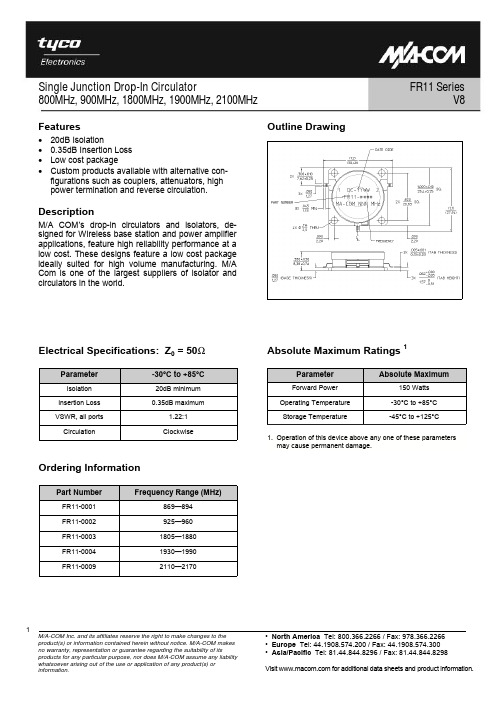
Single Junction Drop-In Circulator800MHz, 900MHz, 1800MHz, 1900MHz, 2100MHzFR11 SeriesM/A-COM Inc. and its affiliates reserve the right to make changes to the product(s) or information contained herein without notice. M/A-COM makes no warranty, representation or guarantee regarding the suitability of its products for any particular purpose, nor does M/A-COM assume any liability whatsoever arising out of the use or application of any product(s) or information. • North America Tel: 800.366.2266 / Fax: 978.366.2266• Europe Tel: 44.1908.574.200 / Fax: 44.1908.574.300• Asia/Pacific Tel: 81.44.844.8296 / Fax: 81.44.844.8298Visit for additional data sheets and product information.V81 Features•20dB Isolation•0.35dB Insertion Loss•Low cost package•Custom products available with alternative con-figurations such as couplers, attenuators, highpower termination and reverse circulation.DescriptionM/A COM’s drop-in circulators and isolators, de-signed for Wireless base station and power amplifierapplications, feature high reliability performance at alow cost. These designs feature a low cost packageideally suited for high volume manufacturing. M/ACom is one of the largest suppliers of isolator andcirculators in the world.Ordering InformationPart Number Frequency Range (MHz)FR11-0001 869—894FR11-0002 925—960FR11-0003 1805—1880FR11-0004 1930—1990FR11-0009 2110—2170Outline DrawingElectrical Specifications: Z0 = 50ΩParameter -30°C to +85°CIsolation 20dB minimumInsertion Loss 0.35dB maximumVSWR, all ports 1.22:1CirculationClockwiseAbsolute Maximum Ratings 11.Operation of this device above any one of these parametersmay cause permanent damage.Parameter Absolute MaximumForward Power 150 WattsOperating Temperature -30°C to +85°CStorage Temperature -45°C to +125°C。
11N90E

Vcc = 450V ID=11A VGS=10V
L=4.92mH, Tch=25°C IF=11A, VGS=0V, Tch=25°C IF=11A, VGS=0V -di/dt=100A/µs, Tch=25°C
Tch=25°C Tch=125°C
FMH11N90E
Super FAP-E3 series
FUJI POWER MOSFET
N-CHANNEL SILICON POWER MOSFET
Features
Maintains both low power loss and low noise Lower RDS(on) characteristic More controllable switching dv/dt by gate resistance Smaller VGS ringing waveform during switching Narrow band of the gate threshold voltage (4.0±0.5V) High avalanche durability
Source(S)
Maximum Ratings and Characteristics
Absolute Maximum Ratings at Tc=25°C (unless otherwise specified)
Description
Drain-Source Voltage
Continuous Drain Current Pulsed Drain Current Gate-Source Voltage Repetitive and Non-Repetitive Maximum AvalancheCurrent Non-Repetitive Maximum Avalanche Energy Repetitive Maximum Avalanche Energy Peak Diode Recovery dV/dt Peak Diode Recovery -di/dt
IPC-A-610F中文版电子组件的检验标准可接受性

IPC-A-610F CN 电子组件的可接受性2014前⾔.................................... 1-1 1.1 范围................................... 1-2 1.2 ⽬的................................... 1-3 1.3 员⼯熟练程度.......................... 1-3 1.4 分级................................... 1-3 1.5 对要求的说明.......................... 1-31.5.1 验收条件............................ 1-4 1.5.1.1 目标条件............................ 1-4 1.5.1.2 可接受条件.......................... 1-4 1.5.1.3 缺陷条件............................ 1-4 1.5.1.3.1 处置................................ 1-4 1.5.1.4 制程警示条件........................ 1-4 1.5.1.4.1 制程控制方法........................ 1-4 1.5.1.5 组合情况............................ 1-4 1.5.1.6 未涉及情形.......................... 1-5 1.5.1.7 特殊设计............................ 1-51.6 术语和定义............................ 1-51.6.1 板面方向............................ 1-5 1.6.1.1 *主面................................ 1-5 1.6.1.2 *辅面................................ 1-5 1.6.1.3 *焊接起始面.......................... 1-5 1.6.1.4 *焊接终止面.......................... 1-5 1.6.2 *冷焊接连接.......................... 1-5 1.6.3 电气间隙............................ 1-5 1.6.4 FOD(外来物) ........................ 1-5 1.6.5 高电压.............................. 1-5 1.6.6 通孔再流焊.......................... 1-6 1.6.7 弯月形涂层(元器件) .................. 1-6 1.6.8 *非功能盘............................ 1-6 1.6.9 针插焊膏............................ 1-6 1.6.10 焊料球.............................. 1-6 1.6.11 线径................................ 1-6 1.6.12 导线重叠............................ 1-6 1.6.13 导线过缠绕.......................... 1-61.7 图例与插图............................ 1-61.8 检查⽅法.............................. 1-6 1.9 尺⼨鉴定.............................. 1-6 1.10 放⼤辅助装置......................... 1-61.11 照明.................................. 1-72 适⽤⽂件................................ 2-1 2.1 IPC标准............................... 2-1 2.2 联合⼯业标准.......................... 2-1 2.3 EOS/ESD协会标准..................... 2-2 2.4 电⼦⼯业联合会标准.................... 2-2 2.5 国际电⼯委员会标准.................... 2-2 2.6 美国材料与测试协会.................... 2-22.7 技术出版物............................ 2-23 电⼦组件的操作.......................... 3-1 3.1 EOS/ESD的预防........................ 3-23.1.1 电气过载(EOS) ....................... 3-3 3.1.2 静电释放(ESD) ....................... 3-4 3.1.3 警告标识............................ 3-5 3.1.4 防护材料............................ 3-6 3.2 EOS/ESD安全⼯作台/EPA ............... 3-73.3 操作注意事项.......................... 3-93.3.1 指南................................ 3-9 3.3.2 物理损伤........................... 3-10 3.3.3 污染............................... 3-10 3.3.4 电子组件........................... 3-11 3.3.5 焊接后............................. 3-11 3.3.6 手套与指套......................... 3-12⽬录IPC-A-610F 2014年7月ix4 机械零部件.............................. 4-1 4.1 机械零部件的安装...................... 4-24.1.1 电气间隙............................ 4-2 4.1.2 妨碍................................ 4-3 4.1.3 大功率元器件安装.................... 4-4 4.1.4 散热装置............................ 4-6 4.1.4.1 绝缘垫和导热复合材料................ 4-6 4.1.4.2 接触................................ 4-8 4.1.5 螺纹紧固件和其它螺纹部件的安装...... 4-9 4.1.5.1 扭矩............................... 4-11 4.1.5.2 导线............................... 4-134.2 螺栓安装............................. 4-15 4.3 连接器插针........................... 4-164.3.1 板边连接器引针..................... 4-16 4.3.2 压接插针........................... 4-17 4.3.2.1 焊接............................... 4-204.4 线束的固定........................... 4-234.4.1 概述............................... 4-23 4.4.2 连轧............................... 4-26 4.4.2.1 损伤............................... 4-274.5 布线–导线和线束..................... 4-284.5.1 导线交叉........................... 4-28 4.5.2 弯曲半径........................... 4-29 4.5.3 同轴线缆........................... 4-30 4.5.4 空置线头........................... 4-31 4.5.5 接头和焊环上的扎点................. 4-325 焊接.................................... 5-1 5.1 焊接可接受性要求...................... 5-3 5.2 焊接异常.............................. 5-45.2.1 暴露金属基材........................ 5-4 5.2.2 针孔/吹孔........................... 5-6 5.2.3 焊膏再流............................ 5-7 5.2.4 不润湿.............................. 5-85.2.5 冷焊/松香焊接连接................... 5-95.2.6 退润湿.............................. 5-95.2.7 焊料过量........................... 5-105.2.7.1 焊料球_________............................. 5-115.2.7.2 桥连............................... 5-125.2.7.3 锡网/泼锡.......................... 5-135.2.8 焊料受扰........................... 5-145.2.9 焊料开裂. .......................... 5-155.2.10 拉尖............................... 5-165.2.11 无铅填充起翘....................... 5-175.2.12 无铅热撕裂/孔收缩. ................. 5-185.2.13 焊点表面的探针印记和其它类似表面状况......................... 5-196 端⼦连接................................ 6-16.1 铆装件................................ 6-26.1.1 接线柱.............................. 6-26.1.1.1 接线柱基座-焊盘间隙................. 6-26.1.1.2 塔形................................ 6-36.1.1.3 双叉形.............................. 6-46.1.2 卷式翻边............................ 6-56.1.3 喇叭口形翻边........................ 6-66.1.4 花瓣形翻边.......................... 6-76.1.5 焊接................................ 6-86.2 绝缘⽪............................... 6-106.2.1 损伤............................... 6-106.2.1.1 焊前............................... 6-106.2.1.2 焊后............................... 6-126.2.2 间隙............................... 6-136.2.3 挠性套管........................... 6-156.2.3.1 放置............................... 6-156.2.3.2 损伤............................... 6-176.3 导体.................................. 6-186.3.1 形变............................... 6-186.3.2 损伤............................... 6-196.3.2.1 多股导线........................... 6-196.3.2.2 实芯线............................. 6-206.3.3 股线发散(鸟笼形)–焊前............ 6-206.3.4 股线发散(鸟笼形)–焊后............ 6-216.3.5 上锡............................... 6-226.5 应⼒释放............................. 6-256.5.1 线束............................... 6-256.5.2 引线/导线弯曲...................... 6-26 6.6 引线/导线放置–通⽤要求.............. 6-28 6.7 焊接–通⽤要求....................... 6-30 ⽬录(续)x 2014年7月IPC-A-610F6.8 塔形和直针形......................... 6-316.8.1 引线/导线放置...................... 6-316.8.2 塔形和直针形–焊接................ 6-336.9 双叉形............................... 6-346.9.1 引线/导线放置–侧面进线连接........ 6-346.9.2 引线/导线放置–导线的加固.......... 6-376.9.3 引线/导线放置–底部和顶部进线连接.. 6-386.9.4 焊接............................... 6-396.10 槽形................................. 6-426.10.1 引线/导线放置...................... 6-42 6.10.2 焊接............................... 6-436.11 穿孔形............................... 6-446.11.1 引线/导线放置...................... 6-44 6.11.2 焊接............................... 6-466.12 钩形................................. 6-476.12.1 引线/导线放置...................... 6-47 6.12.2 焊接............................... 6-496.13 锡杯................................. 6-506.13.1 引线/导线放置...................... 6-50 6.13.2 焊接............................... 6-526.14 AWG30及更细的导线–引线/导线放置.. 6-54 6.15 串联连接............................ 6-557 通孔技术................................ 7-1 7.1 元器件的安放.......................... 7-27.1.1 方向................................ 7-2 7.1.1.1 方向–水平.......................... 7-3 7.1.1.2 方向–垂直.......................... 7-5 7.1.2 引线成形............................ 7-6 7.1.2.1 弯曲半径............................ 7-6 7.1.2.2 密封/熔接处与弯曲起始处之间的距离... 7-7 7.1.2.3 应力释放............................ 7-8 7.1.2.4 损伤............................... 7-10 7.1.3 引线跨越导体....................... 7-11 7.1.4 通孔阻塞........................... 7-12 7.1.5 DIP/SIP器件和插座.................. 7-13 7.1.6 径向引线–垂直..................... 7-15 7.1.6.1 限位装置........................... 7-16 7.1.7 径向引线–水平..................... 7-18 7.1.8 连接器............................. 7-19 7.1.8.1 直角............................... 7-21 7.1.8.2 带侧墙的插针头和直立插座连接器..... 7-22 7.1.9 导体外壳........................... 7-237.2 元器件的固定......................... 7-237.2.1 固定夹............................. 7-23 7.2.2 粘合剂粘接......................... 7-25 7.2.2.1 粘合剂粘接–非架高元器件........... 7-26 7.2.2.2 粘合剂粘接–架高元器件............. 7-29 7.2.3 其它器件........................... 7-30 7.3 ⽀撑孔............................... 7-317.3.1 轴向引线–水平..................... 7-31 7.3.2 轴向引线–垂直..................... 7-33 7.3.3 导线/引线伸出...................... 7-35 7.3.4 导线/引线弯折...................... 7-36 7.3.5 焊接............................... 7-38 7.3.5.1 垂直填充(A) ....................... 7-41 7.3.5.2 焊接终止面–引线到孔壁(B) ......... 7-43 7.3.5.3 焊接终止面–焊盘区覆盖(C) ......... 7-45 7.3.5.4 焊接起始面–引线到孔壁(D) ......... 7-46 7.3.5.5 焊接起始面–焊盘区覆盖(E) ......... 7-47 7.3.5.6 焊料状况–引线弯曲处的焊料......... 7-487.3.5.7 焊料状况–接触通孔元器件本体....... 7-49 7.3.5.8 焊料状况–焊料中的弯月面绝缘层..... 7-50 7.3.5.9 焊接后的引线剪切................... 7-52 7.3.5.10 焊料内的漆包线绝缘层............... 7-53 7.3.5.11 无引线的层间连接–导通孔........... 7-54 7.3.5.12 子母板............................. 7-55 7.4 ⾮⽀撑孔............................. 7-587.4.1 轴向引线–水平..................... 7-58 7.4.2 轴向引线–垂直..................... 7-59 7.4.3 引线/导线伸出...................... 7-60 7.4.4 引线/导线弯折...................... 7-61 7.4.5 焊接............................... 7-63 7.4.6 焊接后的引线剪切................... 7-657.5 跳线.................................. 7-667.5.1 导线的选择......................... 7-66 7.5.2 布线............................... 7-67 7.5.3 导线的固定......................... 7-69 7.5.4 支撑孔............................. 7-71 7.5.4.1 支撑孔–引线在孔内................. 7-71 7.5.5 缠绕连接........................... 7-72 7.5.6 搭焊连接........................... 7-73⽬录(续)IPC-A-610F 2014年7月xi8 表⾯贴装组件............................ 8-1 8.1 粘合剂固定............................ 8-38.1.1 元器件粘接........................ 8-38.1.2 机械强度.......................... 8-4 8.2 SMT引线.............................. 8-68.2.1 塑封元器件........................ 8-68.2.2 损伤.............................. 8-68.2.3 压扁.............................. 8-7 8.3 SMT连接.............................. 8-7 8.3.1 ⽚式元器件–仅有底部端⼦............ 8-88.3.1.1 侧面偏出(A) ...................... 8-9 8.3.1.2 末端偏出(B) ...................... 8-108.3.1.4 侧面连接长度(D) ................. 8-12 8.3.1.5 最大填充高度(E) .................. 8-13 8.3.1.6 最小填充高度(F) .................. 8-13 8.3.1.7 焊料厚度(G) ..................... 8-14 8.3.1.8 末端重叠(J) ...................... 8-14 8.3.2 矩形或⽅形端⽚式元器件–1,3或5⾯端⼦....................... 8-158.3.2.1 侧面偏出(A) ..................... 8-16 8.3.2.2 末端偏出(B) ...................... 8-18 8.3.2.3 末端连接宽度(C) .................. 8-19 8.3.2.4 侧面连接长度(D) ................. 8-21 8.3.2.5 最大填充高度(E) .................. 8-22 8.3.2.6 最小填充高度(F) .................. 8-23 8.3.2.7 焊料厚度(G) ..................... 8-24 8.3.2.8 末端重叠(J) ...................... 8-25 8.3.2.9 端子异常......................... 8-26 8.3.2.9.1 侧面贴装(公告板) ................ 8-26 8.3.2.9.2 底面朝上贴装..................... 8-28 8.3.2.9.3 叠装............................. 8-29 8.3.2.9.4 立碑............................. 8-30 8.3.2.10 居中焊端......................... 8-31 8.3.2.10.1 侧面焊接宽度..................... 8-31 8.3.2.10.2 侧面最小填充高度................. 8-32 8.3.3 圆柱体帽形端⼦..................... 8-338.3.3.1 侧面偏出(A) ....................... 8-34 8.3.3.2 末端偏出(B) ....................... 8-35 8.3.3.3 末端连接宽度(C) ................... 8-36 8.3.3.4 侧面连接长度(D) ................... 8-37 8.3.3.5 最大填充高度(E) ................... 8-38 8.3.3.6 最小填充高度(F) .................... 8-39 8.3.3.7 焊料厚度(G) ....................... 8-40 8.3.3.8 末端重叠(J) ........................ 8-41 8.3.4 城堡形端⼦.......................... 8-428.3.4.1 侧面偏出(A) ....................... 8-43 8.3.4.2 末端偏出(B) ....................... 8-44 8.3.4.3 最小末端连接宽度(C) ............... 8-44 8.3.4.4 最小侧面连接长度(D) ............... 8-45 8.3.4.5 最大填充高度(E) ................... 8-45 8.3.4.6 最小填充高度(F) .................... 8-468.3.5 扁平鸥翼形引线..................... 8-478.3.5.1 侧面偏出(A) ....................... 8-47 8.3.5.2 趾部偏出(B) ....................... 8-51 8.3.5.3 最小末端连接宽度(C) ............... 8-52 8.3.5.4 最小侧面连接长度(D) ............... 8-54 8.3.5.5 最大跟部填充高度(E) ............... 8-56 8.3.5.6 最小跟部填充高度(F) ................ 8-57 8.3.5.7 焊料厚度(G) ....................... 8-58 8.3.5.8 共面性............................. 8-598.3.6 圆形或扁圆(精压)鸥翼形引线.......... 8-608.3.6.1 侧面偏出........................... 8-61 8.3.6.2 趾部偏出(B) ....................... 8-62 8.3.6.3 最小末端连接宽度(C) ............... 8-62 8.3.6.4 最小侧面连接长度(D) ............... 8-63 8.3.6.5 最大跟部填充高度(E) ............... 8-64 8.3.6.6 最小跟部填充高度(F) ................ 8-65 8.3.6.7 焊料厚度(G) ....................... 8-66 8.3.6.8 最小侧面连接高度(Q) ............... 8-66 8.3.6.9 共面性............................. 8-67⽬录(续)xii 2014年7月IPC-A-610F8.3.7 J形引线............................. 8-688.3.7.1 侧面偏出(A) ....................... 8-68 8.3.7.2 趾部偏出(B) ....................... 8-70 8.3.7.3 末端连接宽度(C) ................... 8-70 8.3.7.4 侧面连接长度(D) ................... 8-72 8.3.7.5 最大跟部填充高度(E) ............... 8-73 8.3.7.6 最小跟部填充高度(F) ................ 8-74 8.3.7.7 焊料厚度(G) ....................... 8-76 8.3.7.8 共面性............................. 8-768.3.8 垛形/I形连接........................ 8-778.3.8.1 修整的通孔引线..................... 8-77 8.3.8.2 预置焊料端子....................... 8-78 8.3.8.3 最大侧面偏出(A) ................... 8-79 8.3.8.4 最大趾部偏出(B) ................... 8-80 8.3.8.5 最小末端连接宽度(C) ............... 8-818.3.8.6 最小侧面连接长度(D) ............... 8-82 8.3.8.7 最大填充高度(E) ................... 8-82 8.3.8.8 最小填充高度(F) .................... 8-83 8.3.8.9 焊料厚度(G) ....................... 8-84 8.3.9 扁平焊⽚引线........................ 8-858.3.10 仅有底部端⼦的⾼外形元器件........ 8-868.3.11 内弯L形带状引线................... 8-87 8.3.12 表⾯贴装⾯阵列.................... 8-898.3.12.1 对准............................... 8-90 8.3.12.2 焊料球间距......................... 8-90 8.3.12.3 焊接连接........................... 8-91 8.3.12.4 空洞............................... 8-93 8.3.12.5 底部填充/加固...................... 8-93 8.3.12.6 叠装............................... 8-94 8.3.13 底部端⼦元器件(BTC) ............... 8-968.3.14 具有底部散热⾯端⼦的元器件........ 8-98 8.3.15 平头柱连接........................ 8-1008.3.15.1 最大端子偏出–方形焊盘............ 8-100 8.3.15.2 最大端子偏出–圆形焊盘............ 8-101 8.3.15.3 最大填充高度...................... 8-1018.3.16 P型连接........................... 8-1028.3.16.1 最大侧面偏出(A) .................. 8-103 8.3.16.2 最大趾部偏出(B) .................. 8-103 8.3.16.3 最小末端连接宽度(C) .............. 8-104 8.3.16.4 最小侧面连接长度(D) .............. 8-104 8.3.16.5 最小填充高度(F) ................... 8-105 8.4 特殊SMT端⼦........................ 8-1068.5 表⾯贴装连接器...................... 8-107 8.6 跳线................................. 8-1088.6.1 SMT .............................. 8-109 8.6.1.1 片式和圆柱体帽形元器件............ 8-109 8.6.1.2 鸥翼形引线........................ 8-110 8.6.1.3 J形引线........................... 8-1118.6.1.5 焊盘.............................. 8-1129 元器件损伤.............................. 9-1 9.1 ⾦属镀层缺失.......................... 9-2 9.2 ⽚式电阻器材质........................ 9-3 9.3 有引线/⽆引线器件..................... 9-4 9.4 陶瓷⽚式电容器........................ 9-8 9.5 连接器............................... 9-10 9.6 继电器............................... 9-13 9.7 变压器芯体损伤....................... 9-13 9.8 连接器、⼿柄、簧⽚、锁扣............. 9-14 9.9 板边连接器引针....................... 9-15 9.10 压接插针............................ 9-16 9.11 背板连接器插针...................... 9-17 9.12 散热装置............................ 9-18 9.13 螺纹件和五⾦件...................... 9-19 ⽬录(续)IPC-A-610F 2014年7月xiii10 印制电路板............................ 10-1 10.1 ⾮焊接接触区域...................... 10-210.1.1 脏污............................... 10-2 10.1.2 损伤............................... 10-410.2 层压板状况.......................... 10-410.2.1 白斑和微裂纹....................... 10-5 10.2.2 起泡和分层......................... 10-710.2.4 晕圈.............................. 10-10 10.2.5 边缘分层、缺口和微裂纹............ 10-12 10.2.6 烧焦.............................. 10-14 10.2.7 弓曲和扭曲........................ 10-15 10.2.8 分板.............................. 10-1610.3 导体/焊盘........................... 10-1810.3.1 横截面积的减少.................... 10-18 10.3.2 垫/盘的起翘....................... 10-19 10.3.3 机械损伤.......................... 10-2110.4 挠性和刚挠性印制电路............... 10-2210.4.1 损伤.............................. 10-22 10.4.2 分层/起泡......................... 10-24 10.4.2.1 挠性.............................. 10-24 10.4.2.2 挠性板到增强板.................... 10-25 10.4.3 焊料芯吸.......................... 10-26 10.4.4 连接.............................. 10-2710.5 标记................................ 10-2810.5.1 蚀刻(包括手工描印蚀刻) ............ 10-30 10.5.2 丝印.............................. 10-31 10.5.3 盖印.............................. 10-33 10.5.4 激光.............................. 10-34 10.5.5 标签.............................. 10-35 10.5.5.1 条形码/二维码..................... 10-35 10.5.5.2 可读性............................ 10-36 10.5.5.3 标签–粘合与损伤................. 10-37 10.5.5.4 位置.............................. 10-37 10.5.6 使用射频识别(RFID)标签........... 10-3810.6 清洁度............................. 10-3910.6.1 助焊剂残留物...................... 10-40 10.6.2 外来物............................ 10-41 10.6.3 氯化物、碳酸盐和白色残留物........ 10-42 10.6.4 助焊剂–免洗工艺–外观............ 10-44 10.6.5 表面外观.......................... 10-4510.7 阻焊膜涂覆......................... 10-4610.7.1 皱褶/裂纹......................... 10-47 10.7.2 空洞、起泡和划痕.................. 10-49 10.7.3 脱落.............................. 10-50 10.7.4 变色.............................. 10-5110.8 敷形涂覆........................... 10-5110.8.1 概要.............................. 10-51 10.8.2 覆盖.............................. 10-52 10.8.3 厚度.............................. 10-54 10.8.4 电气绝缘涂敷...................... 10-55 10.8.4.1 覆盖.............................. 10-55 10.8.4.2 厚度.............................. 10-5510.9 灌封................................ 10-5611 分⽴布线.............................. 11-1 11.1 ⽆焊绕接............................ 11-211.1.1 匝数............................... 11-3 11.1.2 匝间空隙........................... 11-4 11.1.3 导线末端,绝缘绕匝................. 11-5 11.1.4 绕匝凸起重叠....................... 11-7 11.1.5 绕接位置........................... 11-8 11.1.6 理线.............................. 11-10 11.1.7 导线松弛.......................... 11-11 11.1.8 导线镀层.......................... 11-12 11.1.9 绝缘皮损伤........................ 11-1311.1.10 导体和接线柱的损伤................ 11-1412 ⾼电压................................ 12-1 附录A 最⼩电⽓间隙–导体间距............ A-1 ⽬录(续)xiv 2014年7月IPC-A-610F本章包括以下内容:1.1 范围................................... 1-2 1.2 ⽬的................................... 1-3 1.3 员⼯熟练程度.......................... 1-3 1.4 分级................................... 1-3 1.5 对要求的说明.......................... 1-31.5.1 验收条件............................ 1-4 1.5.1.1 目标条件............................ 1-4 1.5.1.2 可接受条件.......................... 1-4 1.5.1.3 缺陷条件............................ 1-4 1.5.1.3.1 处置................................ 1-4 1.5.1.4 制程警示条件........................ 1-4 1.5.1.4.1 制程控制方法........................ 1-4 1.5.1.5 组合情况............................ 1-4 1.5.1.6 未涉及情形.......................... 1-5 1.5.1.7 特殊设计............................ 1-51.6 术语和定义............................ 1-51.6.1 板面方向............................ 1-5 1.6.1.1 *主面................................ 1-5 1.6.1.2 *辅面................................ 1-5 1.6.1.3 *焊接起始面.......................... 1-5 1.6.1.4 *焊接终止面.......................... 1-5 1.6.2 *冷焊接连接.......................... 1-5 1.6.3 电气间隙............................ 1-5 1.6.4 FOD(外来物) ........................ 1-5 1.6.5 高电压.............................. 1-5 1.6.6 通孔再流焊.......................... 1-6 1.6.7 弯月形涂层(元器件) .................. 1-6 1.6.8 *非功能盘............................ 1-6 1.6.9 针插焊膏............................ 1-6 1.6.10 焊料球.............................. 1-6 1.6.11 线径................................ 1-6 1.6.12 导线重叠............................ 1-6 1.6.13 导线过缠绕.......................... 1-61.7 图例与插图............................ 1-6 1.8 检查⽅法.............................. 1-6 1.9 尺⼨鉴定.............................. 1-6 1.10 放⼤辅助装置......................... 1-6 1.11 照明.................................. 1-7完整资料:https:///item.htm?id=541142767632QQ:1395833280Mail: **************。
fqa11n90c场效应管参数
标题:深度解密fqa11n90c场效应管参数一、引言在当今科技领域,fqa11n90c场效应管参数作为关键元件,被广泛应用于各种电子产品中。
了解和掌握其参数对于电子工程师来说至关重要。
本文将对fqa11n90c场效应管参数进行深入解析,帮助读者全面理解其特性和应用。
二、基本概念1. fqa11n90c场效应管概述fqa11n90c场效应管是一种半导体器件,通过在控制栅极施加电压来控制其导电能力,具有高输入电阻、低噪声等特点,被广泛应用于功率放大和信号处理等领域。
2. 主要参数fqa11n90c场效应管的主要参数包括漏极-源极饱和电压、漏极-源极漏电流、栅极-源极阈值电压、输入电容等。
这些参数直接影响着场效应管的工作特性和性能。
三、参数解析1. 漏极-源极饱和电压(VDSat)漏极-源极饱和电压是fqa11n90c场效应管的重要参数之一,它表示了在导通状态下,漏极和源极之间的电压。
VDSat的大小影响着场效应管的开关速度和损耗。
2. 漏极-源极漏电流(IDSS)漏极-源极漏电流是指在栅极和源极之间未施加电压时,漏极流过的电流。
漏电流大小与场效应管的温度稳定性和导通能力有关。
3. 栅极-源极阈值电压(VGSth)栅极-源极阈值电压是使得场效应管开始导通的栅极电压。
VGSth的大小直接影响着场效应管的导通起始时间和控制精度。
4. 输入电容(Ciss)输入电容是指在栅极和源极之间的电容。
Ciss的大小与场效应管的高频特性和控制瞬态响应能力密切相关。
四、应用实例分析通过对fqa11n90c场效应管参数的了解,可以更好地应用于电源管理、驱动器和电机控制等领域。
在电源管理中,合理选择场效应管的参数可以提高电源转换效率和稳定性。
五、个人观点作为电子工程师,我认为深入了解fqa11n90c场效应管参数不仅可以提高电路设计的效率,还能够在实际应用中更好地解决问题。
我建议在选型和设计时要充分考虑到场效应管的参数,并进行详细的分析和测试。
11n90e场效应管参数
11n90e场效应管参数摘要:1.场效应管的基本概念与分类2.11n90e场效应管的主要参数3.11n90e场效应管的性能特点与应用领域4.如何选择合适的11n90e场效应管5.总结正文:一、场效应管的基本概念与分类场效应管(Field Effect Transistor,简称FET)是一种根据半导体材料的载流子浓度变化来实现信号放大和开关功能的器件。
根据导电类型和结构的不同,场效应管可分为两类:金属氧化物半导体场效应管(MOSFET)和绝缘栅双极型晶体管(IGBT)。
二、11n90e场效应管的主要参数1.器件型号:11n90e2.沟道材质:氮化镓(GaN)3.栅氧层厚度:10nm4.栅极电压范围:-10V至+10V5.电流容量:10A/cm6.开关速度:10GHz7.线性度:10%8.输入阻抗:1MΩ9.输出阻抗:10Ω10.额定功率:30W三、11n90e场效应管的性能特点与应用领域1.高频性能:11n90e场效应管具有较高的开关速度,适用于高频、高速电子设备。
2.高功率密度:11n90e场效应管具有较高的电流容量,可在较小的封装尺寸内实现高功率输出。
3.低失真:11n90e场效应管具有较低的线性度,可实现高品质信号传输。
4.广泛应用于射频、无线通信、光通信等领域。
四、如何选择合适的11n90e场效应管1.根据电路需求选择器件型号:不同型号的11n90e场效应管具有不同的性能参数,需根据实际应用场景进行选择。
2.确定工作电压和电流:根据电路设计要求,选择合适的工作电压和电流容量的场效应管。
3.考虑开关速度和线性度:高开关速度和低线性度有利于提高电路的工作效率和性能。
4.考虑封装和尺寸:根据电路板空间和散热需求,选择合适的封装尺寸。
五、总结11n90e场效应管作为一种高性能的半导体器件,在射频、无线通信、光通信等领域具有广泛的应用。
在实际应用中,根据电路需求选择合适的11n90e场效应管,可以提高电路的性能和稳定性。
RME FireFace UC中文说明书

Fireface UCX
最强大的便携式 FireWire® 及 USB 音频接口!
TotalMix™
SyncAlign™
SteadyClock ™
SyncCheck™
USB 2.0/FireWire 400 数字输入/输出系统 8+8+2 通道模拟/ADAT/SPDIF 接口 24Bit/192kHz 数字音频 36x18 矩阵路由器 2xMIDI I/O 独立运行 类兼容运行 MIDI 远程控制
安全须知 .......................................................................................................6
概要
1 简介 ...............................................................................................................8
16 设置 Fireface
16.1 设置对话框................................................................................................30 16.2 时钟模式 - 同步 ....................................................................................32
4 简介及主要特点........................................................................................8
- 1、下载文档前请自行甄别文档内容的完整性,平台不提供额外的编辑、内容补充、找答案等附加服务。
- 2、"仅部分预览"的文档,不可在线预览部分如存在完整性等问题,可反馈申请退款(可完整预览的文档不适用该条件!)。
- 3、如文档侵犯您的权益,请联系客服反馈,我们会尽快为您处理(人工客服工作时间:9:00-18:30)。
IDR, Reverse Drain Current [A]
ID, Drain Current [A]
101 150oC
25oC 100
-55oC
10-1 2
※ Notes : 1. VDS = 50V 2. 250μ s Pulse Test
4
6
8
10
VGS, Gate-Source Voltage [V]
3.0 --
5.0
V
VGS = 10 V, ID = 3.5 A
-- 0.91 1.1
Ω
VDS = 50 V, ID = 3.5 A
(Note 4) --
--
S
Dynamic Characteristics
Ciss
Input Capacitance
Coss
Output Capacitance
Crss
Drain-Source Voltage
Drain Current
- Continuous (TC = 25°C) - Continuous (TC = 100°C)
Drain Current - Pulsed
(Note 1)
Gate-Source Voltage
Single Pulsed Avalanche Energy
元器件交易网
FQAF11N90C
Typical Characteristics
BV DSS , (Normalized) Drain-Source Breakdown Voltage
--
40
Units V A A A V mJ A mJ
V/ns W
W/°C °C
°C
Units °C/W °C/W
©2003 Fairchild Semiconductor Corporation
Rev. A, November 2003
FQAF11N90C
元器件交易网Biblioteka ------
--
IGSSF IGSSR
Gate-Body Leakage Current, Forward VGS = 30 V, VDS = 0 V Gate-Body Leakage Current, Reverse VGS = -30 V, VDS = 0 V
--
--
--
--
--
--
10 100 100 -100
VGS Top : 15.0 V
10.0 V
101
8.0 V
7.0 V
6.5 V
6.0 V
Bottom : 5.5 V
100
10-1 10-1
※ Notes : 1. 250μ s Pulse Test 2. TC = 25℃
100
101
VDS, Drain-Source Voltage [V]
Figure 1. On-Region Characteristics
元器件交易网
FQAF11N90C
FQAF11N90C
900V N-Channel MOSFET
QFET®
General Description
These N-Channel enhancement mode power field effect transistors are produced using Fairchild’s proprietary, planar stripe, DMOS technology. This advanced technology has been especially tailored to minimize on-state resistance, provide superior switching performance, and withstand high energy pulse in the avalanche and commutation mode. These devices are well suited for high efficiency switch mode power supplies..
Reverse Transfer Capacitance
VDS = 25 V, VGS = 0 V, f = 1.0 MHz
-- 2530 3290 pF
-- 215 280
pF
-- 23
30
pF
Switching Characteristics
td(on)
Turn-On Delay Time
tr
Turn-On Rise Time
2.5
2.0 V = 10V
GS
VGS = 20V 1.5
1.0
※ Note : TJ = 25℃
0.5
0
5
10
15
20
25
30
ID, Drain Current [A]
Figure 3. On-Resistance Variation vs Drain Current and Gate Voltage
12
V = 180V DS
10 V = 450V
DS
V = 720V
8
DS
6
4
2
※ Note : ID = 11A
0
0
10
20
30
40
50
60
70
QG, Total Gate Charge [nC]
Figure 6. Gate Charge Characteristics
Rev. A, November 2003
--
--
1.4
V
trr
Reverse Recovery Time
VGS = 0 V, IS = 11.0 A,
-- 1000 --
ns
Qrr
Reverse Recovery Charge
dIF / dt = 100 A/µs
(Note 4) -- 17.0
--
µC
Notes:
1. Repetitive Rating : Pulse width limited by maximum junction temperature
©2003 Fairchild Semiconductor Corporation
Rev. A, November 2003
元器件交易网
FQAF11N90C
Typical Characteristics
ID, Drain Current [A]
DS(ON) R [Ω ], Drain-Source On-Resistance
2. L = 37mH, IAS = 7.0A, VDD = 50V, RG = 25 Ω, Starting TJ = 25°C 3. ISD ≤ 11.0A, di/dt ≤ 200A/µs, VDD ≤ BVDSS, Starting TJ = 25°C 4. Pulse Test : Pulse width ≤ 300µs, Duty cycle ≤ 2% 5. Essentially independent of operating temperature
Operating and Storage Temperature Range
Maximum lead temperature for soldering purposes, 1/8" from case for 5 seconds
FQAF11N90C 900 7.0 4.4 28.0 ± 30 960 7.0 12 4.0 120 0.96
td(off)
Turn-Off Delay Time
tf
Turn-Off Fall Time
Qg
Total Gate Charge
Qgs
Gate-Source Charge
Qgd
Gate-Drain Charge
VDD = 450 V, ID = 11.0 A, RG = 25 Ω
--
60 130
ns
100
101
VDS, Drain-Source Voltage [V]
Figure 5. Capacitance Characteristics
Capacitance [pF]
©2003 Fairchild Semiconductor Corporation
VGS, Gate-Source Voltage [V]
IS
Maximum Continuous Drain-Source Diode Forward Current
--
--
7.0
A
ISM
Maximum Pulsed Drain-Source Diode Forward Current
--
-- 28.0
A
VSD
Drain-Source Diode Forward Voltage VGS = 0 V, IS = 7.0 A
Figure 2. Transfer Characteristics
101
100 10-1
0.2
150℃
25℃
※ Notes : 1. VGS = 0V 2. 250μ s Pulse Test
0.4
0.6
0.8
1.0
1.2
1.4
VSD, Source-Drain voltage [V]
Figure 4. Body Diode Forward Voltage Variation with Source Current and Temperature
Electrical Characteristics
