Icc212
MTL基础知识培训

24V电源: ZB24580 单通道,10kA ,负载电流 ≤ 10 A ZB90543 单通道,3kA,负载电流 ≤ 10 48v电源: TP48-N/-G/-I 20KA, 2线制变送器 TP48-3-N/-I-G 20KA 3线制变送器 TP48-3-N 20KA 4线制变送器 220V电源 : MA15/D/1/SI
SD32
SLP32D
单通道,10kA ,适用于: AI,AO,DI,DO
双通道,20kA ,适用于: AI,AO,DI,DO
ZB91333 3通道,10kA , 适用于: AI,AO,DI,DO
仅适用于DI/DO: IOP32D 双通道,20kA,负载电流 ≤ 670 mA IOP32 单通道,20kA,负载电流 ≤ 670 mA ZB24542 三通道,10kA, 负载电流 ≤ 1500 mA 脉冲量信号(10KHz): 12VDC信号:SD16X 单通道,10kA SLP16D 双通道,20kA 24VDC信号: SD32X 单通道,10kA SLP32D 双通道,20kA ZB24539 单通道, 10kA ZB24547 双通道, 10kA
MTL5521 MTL5522 MTL5544 MTL5575
MTL5511 MTL5516C MTL5517 MTL5531 MTL5532 MTL5541 MTL5544D MTL5546 MTL5546Y MTL5576-THC等
MTL5500系列替代MTL5000系列
• • • • • • • • • •
ICC312 IOP32 SCC01 SD07R SLP32D等
MTL浪涌保护器
MTL浪涌保护器常用型号 ICC212 ICC241-T3 IOP32D IOPHC32D SD16R SD32X
TRICONAO卡LOAD监督超载报警及解决方案说明
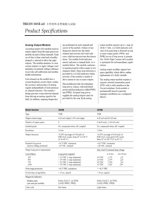
TRICON 3805E AO 卡件特性及带载能力试验:2、P+F KFD2-SCD-Ex1.LK安全栅特性3、MTL ICC212隔离栅特性4、循氢机调速阀静态调试数据表:调速器配置:TRICON 3805E卡件输出经MTL隔离栅MTL5045后到现场电液阀控制调速阀; 调速器输出范围:0~100%-----4~20Ma调速阀开度标尺:0~30格调速器输出开调速阀开度调速器输出关调速阀开度0 % 0 0 % 05 % 2 5 % 210% 3 10% 315 % 4 15 % 420 % 5 20 % 525 % 6 25 % 630 % 7 30 % 735 % 8 35 % 8.540 % 9.5 40 % 1045 % 11 45 % 1150 % 12 50 % 1255 % 13 55 % 1360 % 14 60 % 14.565 % 16 65 % 1670 % 17 70 % 1775 % 18 75 % 1880 % 20 80 % 2085 % 22 85 % 2290 % 23 90 % 2495 % 24 95 % 26100 % 28.5 100 % 28105% 31 105% 315、TRICON AO及P+F安全栅带载静态调试数据表:调速器配置:TRICON 3805E AO卡件输出经P+F安全栅KFD2-SCD-Ex1.LK到电阻箱;KFD2-SCD-Ex1.LK与MTL:5046类似,所以不在列出;调速器输出范围:0~100%-----4~20Ma负载电阻:250欧姆、500欧姆、750欧姆、1000欧姆1100欧姆、1200欧姆、1300欧姆、1400欧姆、1500欧姆、1600欧姆、1700欧姆、1800欧姆、1900欧姆、2000欧姆;系统电压:24.0VDC调速器输出开度负载电阻回路电流负载电压安全栅状态AO卡件状态0 % 250 3.99 1.0 OK OK25 % 250 7.99 2.0 OK OK50% 250 11.99 3.0 OK OK75% 250 16.0 4.0 OK OK100 % 250 20.0 5.0 OK OK调速器输出开度负载电阻回路电流负载电压安全栅状态AO卡件状态0 % 500 3.99 2.0 OK OK25 % 500 7.99 4.0 OK OK50% 500 12.0 6.0 OK OK75% 500 16.0 8.0 OK OK100 % 500 20.0 10.0 OK OK调速器输出开度负载电阻回路电流负载电压安全栅状态AO卡件状态0 % 750 4.0 3.0 OK OK25 % 750 7.99 5.99 OK OK50% 750 12.0 9.0 OK OK75% 750 16.0 12.0 OK OK100 % 750 20.0 15.0 OK OK调速器输出开度负载电阻回路电流负载电压安全栅状态AO卡件状态0 %1000 4.0 4.0OK OK25 %10007.997.99OK OK50%100012.012.0OK OK75%100011.611.6OK OK100 %100011.8711.87LOAD LOAD调速器输出开度负载电阻回路电流负载电压安全栅状态AO卡件状态0 %1100 4.0 4.39OK OK25 %11008.08.8OK OK50%110012.013.18OK OK75%110014.3215.76LOAD LOAD100 %110014.3315.77LOAD LOAD调速器输出开度负载电阻回路电流负载电压安全栅状态AO卡件状态0 %1200 4.0 4.80OK OK25 %12008.09.58OK OK50%120012.014.38OK OK75%1200 6.778.14LOAD LOAD 100 %1200 6.778.14LOAD LOAD调速器输出开度负载电阻回路电流负载电压安全栅状态AO卡件状态0 %1300 4.0 5.21OK OK25 %13008.010.39OK OK50%130012.015.58OK OK75%13007.617.30LOAD LOAD 100 %1300 5.607.30LOAD LOAD调速器输出开度负载电阻回路电流负载电压安全栅状态AO卡件状态0 %1400 4.0 5.58OK OK25 %14008.011.18OK OK50%1400 4.9 6.84LOAD LOAD 75%1400 4.53 6.32LOAD LOAD 100 %1400 4.53 6.31LOAD LOAD调速器输出开度负载电阻回路电流负载电压安全栅状态AO卡件状态0 %1500 4.0 6.0OK OK25 %15008.012.0OK OK50%1500 3.83 5.80LOAD LOAD 75%1500 3.80 5.66LOAD LOAD 100 %1500 3.80 5.66LOAD LOAD调速器输出开度负载电阻回路电流负载电压安全栅状态AO卡件状态0 %1600 4.0 6.41OK OK25 %16008.012.78OK OK50%1600 3.66 5.85LOAD LOAD 75%1600 3.66 5.85LOAD LOAD 100 %1600 3.66 5.85LOAD LOAD调速器输出开度负载电阻回路电流负载电压安全栅状态AO卡件状态0 %1700 4.0 6.80OK OK25 %17008.013.58OK OK50%1700 3.00 5.26LOAD LOAD 75%1700 3.35 5.69LOAD LOAD 100 %1700 3.34 5.69LOAD LOAD调速器输出开度负载电阻回路电流负载电压安全栅状态AO卡件状态0 %1800 4.07.16OK OK25 %18008.014.39OK OK50%1800 3.09 5.57LOAD LOAD75%1800 3.09 5.56LOAD LOAD100 %1800 3.09 5.56LOAD LOAD调速器输出开度负载电阻回路电流负载电压安全栅状态AO卡件状态0 %1900 4.07.60OK OK25 %19008.015.17OK OK50%1900 2.91 5.55LOAD LOAD75%1900 2.91 5.55LOAD LOAD100 %1900 2.92 5.55LOAD LOAD调速器输出开度负载电阻回路电流负载电压安全栅状态AO卡件状态0 %2000 4.07.58OK OK25 %2000严重故障严重故障严重故障严重故障50%2000严重故障严重故障严重故障严重故障75%2000严重故障严重故障严重故障严重故障100 %2000严重故障严重故障严重故障严重故障6、TRICON AO及MTL隔离栅带载静态调试数据表:调速器配置:TRICON 3805E AO卡件输出经MTL隔离栅MTL5045后到电阻箱;ICC212及KFD2-CD-EX1.32与MTL5045类似,所以不在列出;说明:MTL隔离栅ICC212无监督报警功能调速器输出范围:0~100%-----4~20Ma负载电阻:250欧姆、500欧姆、750欧姆、800欧姆、850欧姆、900欧姆、950欧姆、1000欧姆1100欧姆、1200欧姆、1300欧姆、1400欧姆、1500欧姆、1600欧姆、1700欧姆、1800欧姆、1900欧姆、2000欧姆;系统电压:24.5VDC调速器输出开度负载电阻回路电流负载电压AO卡件状态250 3.98 0.99 OK0 %500 3.98 1.99 OK750 3.98 2.98 OK850 3.98 3.38 OK900 3.98 3.57 OK950 3.98 3.79 OK1000 3.98 3.98 OK1100 3.98 4.38 OK1200 3.98 4.78 OK1300 3.98 5.18 OK1400 3.98 5.57 OK1500 3.98 5.98 OK1600 3.98 6.38 OK1700 3.98 6.78 OK1800 3.98 7.18 OK1900 3.97 7.55 OK2000 3.98 7.97 OK调速器输出开度负载电阻回路电流负载电压AO卡件状态250 7.99 1.99 OK500 7.98 3.99 OK750 7.99 5.99 OK800 7.98 6.38 OK850 7.98 6.78 OK900 7.99 7.18 OK950 7.98 7.58 OK1000 7.98 7.98 OK1100 7.98 8.77 OK25 %1200 7.98 9.58 OK1300 7.99 10.37 OK1400 7.98 11.17 OK1500 7.98 11.98 OK1600 7.99 12.79 OK1700 7.97 13.57 OK1800 7.98 14.37 OK1900 7.98 15.18 OK2000 7.98 15.95 OK调速器输出开度负载电阻回路电流负载电压AO卡件状态250 11.98 2.99 OK500 11.98 5.98 OK750 11.98 8.98 OK50 %800 11.98 9.58 OK850 11.98 10.18 OK900 11.98 10.78 OK1000 11.98 11.98 OK1100 11.98 13.18 OK1200 11.98 14.37 OK1300 11.98 15.57 OK1400 11.98 16.77 OK1500 11.98 17.97 OK1600 11.98 19.16 OK1700 11.99 20.38 OK180011.6721.00OK190011.1321.13OK200010.6321.25OK调速器输出开度负载电阻回路电流负载电压AO卡件状态250 15.99 3.99 OK500 15.99 7.99 OK750 15.99 11.99 OK800 15.99 12.78 OK850 15.99 13.58 OK900 15.99 14.38 OK950 15.99 15.18 OK1000 15.99 15.98 OK1100 15.99 17.58 OK75 %1200 15.99 19.17 OK130015.5220.18OK140014.5820.40OK150013.7320.60OK160012.9820.76OK170012.3020.91OK180011.6921.05OK190011.1421.17OK200010.6421.28OK调速器输出开度负载电阻回路电流负载电压AO卡件状态250 19.99 4.99 OK500 19.99 9.98 OK750 19.99 14.99 OK800 19.99 15.99 OK 100 %850 19.99 16.98 OK900 19.99 17.98 OK950 19.99 18.98 OK100019.4019.39OK110017.9319.72OK130015.5720.24OK 140014.6120.44OK 150013.7620.63OK 160012.9920.79OK 170012.3220.94OK 180011.7021.06OK 190011.1421.19OK 200010.6521.28OK。
量表的信度及其影响因素

考虑使用逐渐激发免疫反应。
如果以前的反应被推测为IgE诱导的,若再次服用此药的话,必须采用一种可替代逐渐激发的处理。
如有某种皮肤试验用药,病人应做皮试。
阳性风团块且发红的皮肤反应表明:有药物特殊的IgE抗体存在,而对于有某种阴性预测值较高试验的某种阴性皮肤试验(如:抗淋巴细胞球蛋白、链激酶、青霉素),则表明这些抗体缺乏。
由于在大多数的病例中,阴性预测值尚不知晓,因此,如果病人皮试结果阴性,病人不能被假定为缺少药物特殊的IgE抗体。
对于这种阴性病人亦或那些皮试结果阳性的病人,靠脱敏这一过程,药物过敏的病人被从某种高敏状态转变为对该药物的可耐受状态。
7 结论有药物反应的病人用药,使得病人及医生都发怵,具有多种药物不良反应的病人最害怕用药。
他们觉得:自己对所有药物都过敏。
对这类病人,医生应找寻非常谙熟如何给药物过敏病人服药的专家给予帮助。
最为重要的是:医生与病人必须了解有关这方面的知识。
所有医生在给病人进行药物治疗时,应遵循一些简单的常识:那些对多种抗生素敏感及那些似乎经常需要使用抗生素的病人,在开始使用抗生素治疗前应获得其感染的客观的证据。
如果是复发的感染,那么应对他们积极地治疗以确保他们不再复发;同时,任何可以使感染加重的机体结构的异常,如免疫缺陷也应被评估。
只有当病人确实需要用药时才可使用。
每一种药物都或多或少地存在着不良反应,且在这些不良反应中,有些可危及生命。
因此,医生们应十分了解自己处方中所开的药物,而且必须采用正确的处方知识,只有如此才可降低药物性疾病的发病率。
参考文献1 D e Shazo R et al.JAM A,1997,278:1895-19062 P ir moham ed M et al.BM J,1998,316:1295-12983 Rom ano A et al.A llergy,1995,50:113-118(收稿:2001205229)量表的信度及其影响因素安胜利 陈平雁解放军第一军医大学卫生统计学教研室(广州,510515) 摘要 量表在医疗卫生领域中的应用日益广泛,信度是评价量表的最重要的指标之一。
MTL

投放地区
4 中国区办事处:广州、北京、上海
业绩
多年来在中国所有的大型石化企业的装置大量应用,占主装置进口安全栅份额的7 上。尤其在近几年百万吨乙烯和千万吨炼油项目中90%均采用MTL安全栅,如兰州 5 烯,茂名乙烯,赛科100万吨乙烯,福建100万吨乙烯一体化(含1000万吨炼油), 1000万吨大炼油,青岛1000万吨大炼油,燕山石化1000万吨炼油改造,广石化800 炼油,武石化800万吨炼油。
交付方式
6 4-6周交货周期、款到发货
资质
7 Zone 0 IIC T4–6、取得IEC的SIL2认证,技术上亦可实现SIL3的安全标准
销售模式
8
项目、成套 国内市场主要发展中间商营销模式
围小
一样精度 性。 2. 节省机柜空间,减少机柜 缩短开车调试周期。 4.
eywell, ABB, s。
产品报价 产品参数
MTL
根据采购数量和具体项目可以申请不同的折扣
(中间商价格)
隔离器
无源过程隔离器
ICC241-T3 ¥362.00
热电阻电流输出隔离器 MTL5575 ¥858.00
1
直流信号隔离器 直流信号隔离器
ICC312 ICC212
¥662.00 ¥391.00
安全栅
操作端隔离安全栅
MTL5541 ¥482.00
投放行业
MTL产品已广泛应用于化工及石油化工、水处理、冶金、制药、电力、水泥、纸浆 纸、公用事业自动化等领域。 在冶金钢铁行业中MTL安全栅的基本可以说是起到了举足轻重的作用。冶金行业任 漏或溅出都有可能形成一个爆炸环境。为了工厂和人员的安全,必须确保这个环境 被点燃引起爆炸。冶金行业煤气加压站、转鲁煤气加压站、高炉煤气加压站都必须 3 安全栅。连接变电器、传感器等实施现场防爆措施。 MTL安全栅在冶金配电室检测端配电隔离安全栅由安全区向危险区现场变送器供电 每个变送器提供独立的隔离电源,电源输入输出相互隔离。冶金行业防爆场合的仪 接,通过安全栅与本安仪表组成本安回路,起到本安防爆的作用。除了用在冶金行 MTL安全栅还广泛应用于化工及石油化工、水处理、电力、水泥、造纸、公用事业 化等领域。
基于数字IC测试机架构详细讲解测试理论
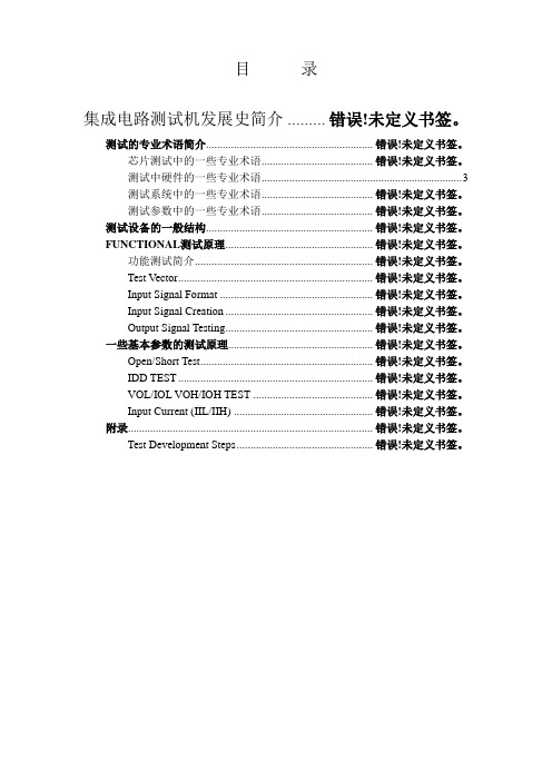
目录集成电路测试机发展史简介 ......... 错误!未定义书签。
测试的专业术语简介............................................................ 错误!未定义书签。
芯片测试中的一些专业术语........................................ 错误!未定义书签。
测试中硬件的一些专业术语 (3)测试系统中的一些专业术语........................................ 错误!未定义书签。
测试参数中的一些专业术语........................................ 错误!未定义书签。
测试设备的一般结构............................................................ 错误!未定义书签。
FUNCTIONAL测试原理..................................................... 错误!未定义书签。
功能测试简介................................................................ 错误!未定义书签。
Test Vector ...................................................................... 错误!未定义书签。
Input Signal Format ....................................................... 错误!未定义书签。
Input Signal Creation ..................................................... 错误!未定义书签。
仪表车间DCS专业题库
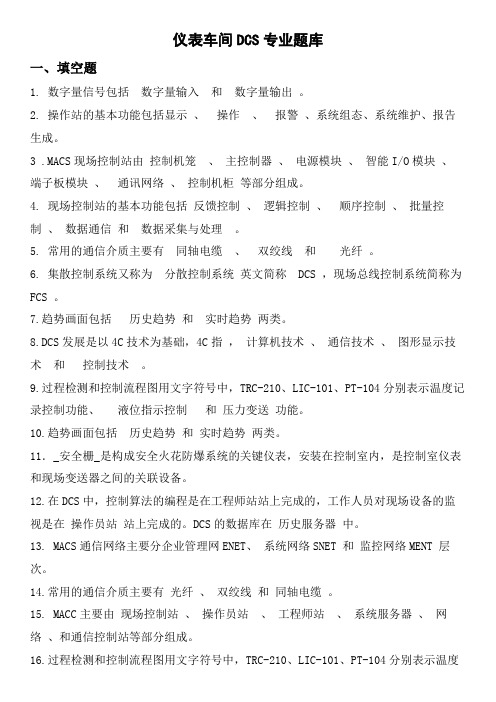
仪表车间DCS专业题库一、填空题1. 数字量信号包括数字量输入和数字量输出。
2. 操作站的基本功能包括显示、操作、报警、系统组态、系统维护、报告生成。
3 .MACS现场控制站由控制机笼、主控制器、电源模块、智能I/O模块、端子板模块、通讯网络、控制机柜等部分组成。
4. 现场控制站的基本功能包括反馈控制、逻辑控制、顺序控制、批量控制、数据通信和数据采集与处理。
5. 常用的通信介质主要有同轴电缆、双绞线和光纤。
6. 集散控制系统又称为分散控制系统英文简称 DCS ,现场总线控制系统简称为FCS 。
7.趋势画面包括历史趋势和实时趋势两类。
8.DCS发展是以4C技术为基础,4C指,计算机技术、通信技术、图形显示技术和控制技术。
9.过程检测和控制流程图用文字符号中,TRC-210、LIC-101、PT-104分别表示温度记录控制功能、液位指示控制和压力变送功能。
10.趋势画面包括历史趋势和实时趋势两类。
11._安全栅_是构成安全火花防爆系统的关键仪表,安装在控制室内,是控制室仪表和现场变送器之间的关联设备。
12.在DCS中,控制算法的编程是在工程师站站上完成的,工作人员对现场设备的监视是在操作员站站上完成的。
DCS的数据库在历史服务器中。
13. MACS通信网络主要分企业管理网ENET、系统网络SNET 和监控网络MENT 层次。
14.常用的通信介质主要有光纤、双绞线和同轴电缆。
15. MACC主要由现场控制站、操作员站、工程师站、系统服务器、网络、和通信控制站等部分组成。
16.过程检测和控制流程图用文字符号中,TRC-210、LIC-101、PT-104分别表示温度记录控制功能、液位指示控制功能和压力变送功能。
17.趋势画面包括历史趋势和实时趋势两类。
18.集散控制系统的组态包括硬件组态和软件组态。
19. 列举你知道的DCS系统有浙大中控JX-300XP 、和利时MACS 、艾默生DeltaV 等。
20.DCS发展是以4C技术为基础,4C指,计算机技术、控制技术、图形显示技术和通信技术。
GCAN-212 Customized CAN bus converter with CPCI port USER MANUAL
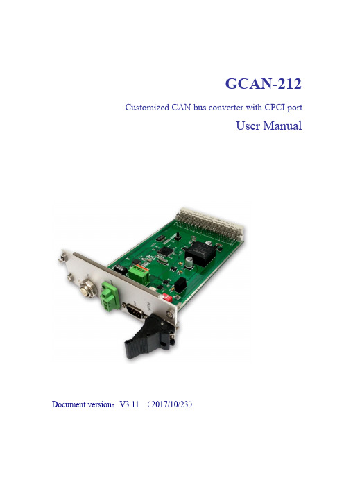
GCAN-212Customized CAN bus converter with CPCI portUser ManualDocument version:V3.11(2017/10/23)Contents1.Introduction (3)1.1Overview (3)1.2Properties at a glance (3)2.Converter used (5)2.1GCAN-212converter Ethernet working mode (5)2.2GCAN-212configuration (5)2.3Connect to Ethernet (5)2.4Connect to CAN-Bus (6)2.5System LED (6)3.TCP protocol format (8)3.1CANopen slave station to Ethernet(RPDO) (8)3.2Ethernet to CANopen slave station(TPDO) (8)3.3Check bit calculation method (9)4.Configuration instructions (10)4.1GCAN-212connection (10)4.2Configuring communication basic information (11)4.3Complete configuration (12)4.4Upgrade the firmware (12)5.Technical specifications (13)1.Introduction1.1OverviewGCAN-212is a customized converter with one or two CAN bus interfaces.The converter has integrated CPCI interface,so it can be used to IPC which communicate through CPCI bus.The GCAN-212can customize multiple communication interfaces such as:Ethernet, Serial bus,USB,and so ers can use the customized converter into their own system and connect it to CAN bus.Note:The following chapter and parameters are all customized to CANopen-Ethernet.1.2Properties at a glance1.2.1Hardware●High-speed32-bit MCU●Built-in FLASH storage,parameters and mapping table can be stored.●Power supply:DC9~30V(40mA,24VDC),others can be customized.●Electrostatic discharge immunity level:contact discharge±6KV,air discharge±15KV●Electrical fast transient burst immunity level:±1KV●Surge immunity level:±1KV●Operating temperature range:-40℃~+85℃●Operating humidity range:5%to95%RH no condensation●PCB Dimensions:160mm*100mm*1.6mm●Meet the relevant standards of shock and vibration in vehicle EN50155●For the power part,the following standards should be met:1.2.2CANopen attribute●Integrated1CAN-Bus interface with standard DB9male head CAN interface with locking device(customized)●CAN-Bus signals include:CAN_H,CAN_L,CAN_GND●CAN-Bus isolation converter insulation voltage:DC1500V●32hardware FIFO receive buffers,the highest received data traffic:8000frames/sec●CAN-Bus supports CANopen protocol(customized),support NMT,PDO,SDO, Heartbeat,Guardlife,SYNC●CAN-Bus baud rates range from5Kbps to1Mbps●CANopen node number supports1~127●CANopen supports8TPDO,8RPDO,2SDO●The node address can be configured by DIP switch1.2.3Ethernet attribute●The PC interface uses standard Ethernet interface.RJ45,support10/100M adaptive●Support static or timeout interrupt function●The connection resource is restored automatically after the network is disconnected●Support protocols include ARP,IP,ICMP,UDP,DHCP,DNS,TCP●Compatible with SOCKET work(TCP server,TCP client),the host computer communication software follows the standard SOCKET rules2.Converter usedGCAN-212can use computer software to configure the basic operation parameters, such as CAN bus baud rate,CANopen node ID,Ethernet IP address,gateway and so on.2.1GCAN-212converter Ethernet working modeGCAN-212converter Ethernet uses standard TCP Server working mode.In this mode, the GCAN-212converter does not automatically connect with other equipment.It can communicate with the client after establishing the TCP connection.The process of establishing communication is shown in figure2.1Figure2.1TCP Server Schematic diagram of mode communication2.2GCAN-212configuration2.2.1Restore factory settingsThe GCAN-212converter's defaults IP:192.168.1.10.If the user has modified the IP and forgot,then it can be reset by using the DIP switch in the device.2.2.2Change PC IP addressPC and GCAN-212IP must be in the same network segment.For example:converter IP:192.168.1.10,PC IP:192.168.1.1.Please note:PC IP cannot be the same as the converter IP.2.3Connect to EthernetThe Ethernet interface of the GCAN-212converter integrates a10/100M adaptive Ethernet chip.The converter conforms to the Ethernet standard protocol specification.2.4Connect to CAN-BusIn practical use,users only need to connect the CAN_H to CAN_H and CAN_L to CAN_L,then communication can be realized.The CAN-Bus network adopts topological structure,only the two furthest terminal need to connect120Ωterminal resistance between CAN_H and CAN_L.For branch connection,its length should not be more than3meters.CAN-Bus nodes connection as shown in figure2.2.Figure2.2CAN-Bus networkNote:CAN-Bus using ordinary twisted pair.The relationship between the bus length and baud rate is shown in Table2.1.Table2.1:table2.5System LEDGCAN-212converter with one SYS indicator,one DAT indicator.More functions are shown in table2.2.Table2.2GCAN-212converter status LEDAfter power on the converter,the SYS indicator light indicates that power is being supplied and the system is initializing;otherwise,it indicates power failure or an error occurred.If the bus has data transmission,DAT indicator will flash.Table2.3Indicator light status of GCAN-2123.TCP protocol format3.1CANopen slave station to Ethernet(RPDO)3.2Ethernet to CANopen slave station(TPDO)3.3Check bit calculation methodThe red data part is cumulative.That is,checksum and=data1+data2+...+data32,if the checksum is greater than255,then take the result of low8bit results.4.Configuration instructions4.1GCAN-212connectionThe software needs to connect to the GCAN-212and fill in the IP address of the converter.If you forget the address,you can reset to the factory settings.Click on the"Connect"connection"Connect"-connect equipment"Upload"-read out the configuration information in the converter "DownLoad"-download the configuration information to the converter Flash "Open"-open and read the configuration information file in the PC "SaveAs"-save the configuration information file to your computer4.2Configuring communication basic informationConnection is successful,click the"UpLoad"to upload the parameters in the device to the computer.Enter the Communication Setting interface,and see the parameters and modify."IP Address Info"-set GCAN-212IP address"GateWay"-set the GCAN-212gateway address"Subnet Mask"-setting the GCAN-212subnet mask"Can Baudrate"--setting baud rate of CAN bus communication"Node ID"-setting the node ID number of the CANopen end"TCP TIME"-set the Ethernet end to send the RxPDO cycle,the unit is Ms. "CAN Baudrate"can set the baud rate of the CAN bus,the corresponding table is as follows:650Kbps720Kbps810Kbps4.3Complete configurationIf any of the parameters change,the corresponding will turn red in the software.Click the"DownLoad"to download the configuration information to the Flash.Note:after downloading,you need to power again,and the new configuration will work.4.4Upgrade the firmwareThis function must be used under guidance.5.Technical specifications。
护生道德敏感性量表的汉化及信效度检验
护生道德敏感性量表的汉化及信效度检验张含静,李红玉*,李松,张艳丽,李玥桐,胡存杰锦州医科大学护理学院,辽宁 121001Chinese version of Moral Sensitivity Questionnaire for Nursing Students and its reliability and validity testZHANG Hanjing, LI Hongyu, LI Song, ZHANG Yanli, LI Yuetong, HU CunjieSchool of Nursing, Jinzhou Medical University, Liaoning 121001 ChinaCorresponding Author LIHongyu,E⁃mail:*****************Abstract Objective:To translate the Moral Sensitivity Questionnaire for Nursing Students(MSQ⁃ST) into Chinese,and to test its reliability and validity.Methods:The Chinese version of MSQ⁃ST was formed through translation,back translation,cross⁃cultural adaptation and pre⁃test based on Brislin principles.The reliability and validity of Chinese version of MSQ⁃ST were tested by means of questionaire among 520 nursing students from 2 medical colleges in Jinzhou.Results:The Chinese version of MSQ⁃ST included 3 dimensions and 11 items.The item⁃content validity index(I⁃CVI)ranged from 0.833 to 1.000,and the average of scale⁃content validity index(S⁃CVI/Ave) was 0.924.Exploratory factor analysis extracted three common factors,and the cumulative contribution rate of variance was 62.423%.Confirmatory factor analysis showed that the model fit well.The Cronbach's α coefficient was 0.809,the overall test⁃retest reliability was 0.726,and the split⁃half reliability was 0.712.Conclusion:The Chinese version of MSQ⁃ST had good reliability and validity,which could be used as a tool to evaluate the moral sensitivity of nursing students.Keywords nursing students; moral sensitivity; reliability; validity摘要目的:对护生道德敏感性量表(Moral Sensitivity Questionnaire for Nursing Students,MSQ⁃ST)进行汉化,并验证其信效度。
ICC
ICC系列信号隔离器MTL Instruments China Co. LtdMTL仪器仪表有限公司ICC211信号隔离器用于电流或电压隔离器特点:输入、输出隔离输入信号4-20mA/0-20mA/10-50mA输出信号4-20mA/1-5Vdc消除接地问题T或G型DIN导轨安装ICC211用于回路供电,将现场变送器,传感器等传送的电流信号进行隔离;由于消除回路的接地问题,接线非常简单。
内置的输入输出回路电阻可以提供对简单信号的检测功能。
(输出回路10Ω对4-20mA,250Ω对1-5V)参数说明:通道数:单通道输入信号:4-20mA (ICC211-I1-XX)0-20mA (ICC211-I2-XX)10-50mA (ICC211-I3-XX)输出信号:4-20mA (ICC211-XX-O1)1-5V (ICC211-XX-O2)输入输出和电源的隔离强度:1500V dc/ac供电电压:4-20mA输出 Vs最小=17+(RL×0.02)V dc Vs最大=35V dc1-5V 输出 Vs=22-35V温差精度:<0.01%环境温度:-20℃-55℃(工作温度) -40℃-80℃(储存温度) 湿度: 5-95%RH订购选型:ICC211-I1-O1 4-20mA输入及输出ICC211-I2-O1 0-20mA输入,4-20mA输出ICC211-I3-O1 10-50mA输入,4-20mA输出ICC211-I1-O2 4-20mA输入,1-5V输出ICC211-I2-O2 0-20mA输入,1-5V输出ICC211-I3-O2 10-50mA输入,1-5V输出ICC212信号隔离器用于智能变送器供电和隔离特点:输入、输出和电源三端隔离变送器供电用于智能变送器数字量的传送能用于其他的转换器供电或者驱动器T或G型DIN导轨安装ICC212是双重功能,带3个端口的电流转换隔离器。
参数说明:通道数:单通道输入输出信号范围:0-20mA 一般的工作范围4-20mA 数字量通讯输入输出和电源的隔离强度:1500V dc/ac供电电压(Vs):20-35V数字信号范围:100Hz-10kHz最大阻抗值:常规变送器:650Ω智能变送器:220Ω-650Ω温漂: 1μA/℃环境温度范围:-20℃-+55℃湿度范围:5%-95%RHICC221信号隔离器用于温度变送器,电偶输入隔离特点:输入、输出电流隔离电偶输入输出可选:1-5V或4-20mA消除接地问题T或G型DIN导轨安装ICC221是将现场低电平热电偶或毫伏信号转换成4-20mA或1-5V输出。
Gas Logs Fireplace 产品说明书

C60FIREPLACE Installation Reference GuideNon-Combustible Board PlacementMantel ProjectionsMantel graph dimensions are measured from the bottom of the fireplace, if you wish to reference the mantel height from the tiling edge subtract 15 inches (381mm) from the mantel height depicted on the graph. If you plan to install a TV above your fireplace refer to the appropriate section of the owner’s manual for available options. It is acceptable to install a combustible mantel over top of the non-combustible board. If y ou are activating the Cool Surface System you are eligible to subtract 12” (305mm) from the mantel height shown in this diagram.Minimum Venting RequirementsMinimum venting is shown in figure 20. the framing height to the center of the thimble is 62”. Minimum venting must include a 24” vertical section and a 90 degree elbow which is then terminated horizonta lly. For a vertica l termina tion plea se follow the vent pipe ma nufa cturer’s insta lla tion instructions for vertica l vent termination framing. A minimum of 1 in. (25 mm) clearance on all sides of the vertical vent pipe must be maintained. For every 12” of horizontal run there must be a 1/4” of rise. 1” of clearance between framing and venting must be maintained at all times. 2” above the venting and 3” above an elbow.Fireplace Dimensions1 2 3 45 6 7 8 9 10 11 12 13 14M A N T L E H E I G H TM A N T L E D E P T HMinimum Mantle Clearances8” MANTLE4”MANTLE47”46”45”44”43”42”41”39”40”12” MANTLE56 1/2”13 3/4”10”COMBUSTIBLENON COMBUSTIBLEFramingMetalStud Drywall Concrete BoardSidewall7”5 3/1672714"186mm3034"779mm 62"1575mm 65"1651mm 914"235mm 1612"422mm 1214"308mm 4"103mm 914"232mm 38"965mm 3"73mm 914"232mm 7"176mm 314"81mmGas Inlet Bottom (Optional)20"507mm12"13mm7034"1797mm1734"453mm Figure 1. Unit Dimensions714"186mm 3034"779mm 62"1575mm 65"1651mm914"235mm1612"422mm 1214"308mm 4"103mm 914"232mm 38"965mm 3"73mm 914"232mm 7"176mm 314"81mmGas InletBottom (Optional)20"507mm 12"13mm 7034"1797mm1734"453mmElectrical Inlet Left Side Figure 1. Unit Dimensions714"186mm 3034"779mm 62"1575mm 65"1651mm 914"235mm 1612"422mm 1214"308mm 4"103m 914"232mm 38"965mm 3"73mm914"232mm 7"176mm 314"81mmGas Inlet Bottom (Optional) 20"507mm12"13mm 7034"1797mm 1734"453mm Figure 1. Unit Dimensions 714"186mm3034"779mm 62"1575mm 65"1651mm 914"235mm1612"422mm1214"308mm 4"103mm 914"232mm 38"965mm 3"73mm 914"232mm 7"176mm 314"81mm Gas Inlet Bottom (Optional)20"507mm12"13mm7034"1797mm1734"453mm9"231mm15"378mmFigure 1. Unit Dimensions714"186mm3034"779mm62"1575mm65"1651mm914"235mm1612"422mm1214"308mm4"103mm 914"232mm38"965mm3"73mm914"232mm7"176mm314"81mm Gas Inlet Bottom (Optional)20"507mm12"13mm7034"1797mm1734"453mmGas Inlet Right Side Figure 1. Unit Dimensions20"509mm62"[1575mm]*Do not use two 12” vent sections or this dimension will not e one 24”section.Dimensions758"(19.4 cm)45" (114.3 cm) 3134" (80.6 cm)25" (63.5 cm)5" Vent Collars40" (101.6 cm) 938"(23.8 cm)234" (7 cm) Standoff212" (6.6 cm) Standoff1178"(30.2 cm)738"(18.7 cm)218"(5.4 cm)12"(1.3 cm)312" (8.9 cm)258" (6.7 cm)CSS Front Vent - Overall Dimensions (C34/C44/C60)CSS Side Vent - Dimensions938"237mm1178"301mm7178"1825mm234"70mm212"64mm7678"1952mm5112"1308mm758"192mm5" Vent Collars218"53mm12"13mm312"89mm258"67mm714"185mm53"1346mmFigure 4. Cool Surface System Front Vent - Overall Dimensions (C72)8.006.178.4214.390.882.637.47 11.746.074.6510.727.670.5012.1814.921.3912.2413.644.754.759.9526.0036.004.7536.009.752.48.49.92.50.502.004.75 .50.492.48Figure 5. Cool Surface System Combustible Facing Kit DimensionsFraming & Rough Opening – Side VentFraming & Rough Opening – Front VentCSS Outlet Min. Top and Bottom standoff = 25/8” (6.7 cm) *All C Series*7 1/2"(2.5 cm)45" (114 cm)37 1/4"(94.6 cm)Min.Height2 x 4 (On Edge)2 x 4 (O n E d g e )C347 1/2"(2.5 cm)C44/60 = 45" (114 cm)2 x 4 (O n E d g e )37 1/4" (94.6 cm) Min.Height C60 = 71" (180 cm)C44 = 55" (140 cm)Steel Stud - C60 & C72 ONLYSteel Stud - C60 & C72 ONLYC72 = 83" (211 cm)46 1/2" (118 cm)Min. HeightC72C34 C60C44C72 = 77 1/4" (196 cm)C44/C60/C72CSS Outlet Min. Top and Bottom standoff = 25/8” (6.7 cm) *All C Series*Min. Height 51-3/8”( 130cm)C34 = 45” (114cm)C44 = 55” (140cm)C60 = 71” (180cm)C72 = 83” (211cm)Revised Mantel Requirements:Note: Minimum height of mantle if you intend on using a surround is 31”1 2 3 45 6 7 8 9 10 11 12 13 14M A N T L E H E I G H TM A N T L E D E P T HMinimum Mantle Clearances8” MANTLE4”MANTLE35”34”33”32”31”30”29”27”28”12” MANTLEVenting Clearances - Front VentShown here are the minimum framing and clearances for the CSS when the fireplace is installed with the minimum allowable vent length:Min. Ceiling Clearance from top of CSS outlet = 4” (10.2 cm)Min. Ceiling Clearance in wall from top of CSS Body = 55/8” (14.3 cm)CSS Body Min. Rear standoff = 2¾” (69.8 cm)558" (14.3 cm)4" (10.2 cm)234" (69.8 cm)7314"(174.9 cm)Side Brace Min. Height20" (50.8 cm)Min. Depth39” (99 cm) Min. Length 5” dia. flex vent(not supplied)80” (203 cm) C34/44/60 Min. CeilingMin. Vent82 3/8”(212 cm) Side Brace Min. Height91” (231 cm)C72 Min. CeilingC34C44C60C72Venting Clearances – Side VentCSS Horizontal Vent - Min. Framing & Clearances CSS Vertical Vent - Min. Framing & Clearances15.00” (38cm)11.50”(29cm)Min. Height to Ceiling 14.50Min. Height 66.00”(168cm)Min. to Ceiling 5” (12.5cm)Min. Height from oor69.5” (176.5cm)39” (99 cm) Min. Length 5” dia. flex vent(not supplied)Min. VentMin. Distance to wall from standoff 5.00” (13cm)Min. Ceiling Height 18.75”(48cm)*15.75” (40c m )11.5” (29cm)Min. Dist 61.75”(157cm)*NOTE: 15.75” from the header is required for min. ceiling height. Rest unit on lower standoff. There will be a 3/4“ (2cm) gap on from the top standoff to the header in this confirguration. Min Framing is 15” x 11.5”3/4” (2cm) Gap ShownMin. Distance to Ceiling 4.5” (11.5cm)Min. Distance to oor64” (162.5cm)39” (99 cm) Min. Length 5” dia. flex vent (not supplied)TV Installation Considerations:If you are planning to mount a TV above your fireplace some considerations must be made to ensure it is protected from the heat.During testing temperatures did not exceed 121°F (49°C) midway up the front wall (Figure 12 & 13). There is no guarantee that these temperatures will not harm the longevity of your TV. Make sure to consult your TV manufacturer’s specifications to find the maximum allowable operatingtemperature. Since every home and installation is unique, temperatures should be verified at the time of install if possible. If desired, front walltemperatures can be lowered to 104°F (40°C) with the use of a mantle (Figure 13). Refer to page 7 for revised mantle clearances. A TV should not be installed if temperatures exceed the manufacturers maximum allowable temperature.Figure 12. CSS - TV Clearances Figure 13. CSS - TV Clearances29°F 41”21°F 35”21°F 29”24°F 23”17°F 17”20°F 11”30°F 5”0”A b o v e A m b i e n tH e i g h t f r o m O p e n i n g4” Mantle 29” from oor.Combustible Facing Kit1/2” Combustible Base Material (Drywall)Up to 1” Combustible Material.NOTE: You cannot install a Surround with the mantle at its lowest position.Install mantle at 31” for a SurroundMin. 2-1/2” (6.4cm)Min. 2” (5cm)Gap Combustible Facing Kit1/2” Combustible Base Material (Drywall)Up to 1” Combustible Material 29°F 41”29°F 35”29°F 29”27°F 23”35°F 17”38°F 11”49°F 5”0”A b o v e A m b i e n tH e i g h t f r o m O p e n i n g1-1/2” Air Gap behind the TV.(Typically provided by a wall mount)TV must be 5” min from discharge if no mantleFraming Clearances - Front VentFraming Clearances - Side Vent29 “(74cm)31 “(79cm)Min. Height For Surround33“(84cm)4” (102mm)8” (203mm)12” (305mm)2-1/16”(75cm)Min. Height to Ceiling 55-1/16” (1399cm)Min. Height to Ceiling 64 1/8”(1630mm)C34C44C60C7229 “(74cm)31 “(79cm)Min. Height For Surround33“(84cm)4” (102mm)8” (203mm)12” (305mm)2-1/16”(75cm)Min. Height to Ceiling 55-1/16” (1399cm)。
ISDGP条款及应用

这需要一份成文的国际标准实 务 ,来支撑见索即付保函的国际 统一操作。
三是见索即付保函的国内应 用中的问题也对标准实务提出了 要 求 。2016年最高院独立保函 司法解释明确了独立保函的国内 法 律 地 位 以 来 ,国 内交易中,见
索即付保函逐步从传统的从属性保函分离出 来 。但 其 中 也 存 在 一 些 突 出 问 题 。 比如在保 函 条 款 中 ,见索即付保函条款与从属性保函 条 款 同 时 出 现 ,保 函 文 本 多 样 且 不 完 善 ,各 商 业 银 行 保 函 操 作 的 差 异 也 较 大 等 。 国际商 会 关 于 标 准 实 务 的 正 式 出 版 物 ,对促进中国 的独立保函应用具有特殊意义。
IS D G P 是见索即付保函发展的必 然要求
国 际 交 易 中 ,见索即付保 函 广 泛 应 用 于 国 际 贸 易 、国际工 程 承 包 、国 际 投 融 资 领 域 ,通过 提 供 高 效 的 担 保 和 增 信 支 持 ,促 进 交 易 达 成 。国 内 交 易 中 ,除了 传 统 的 商 业 领 域 ,见索即付保函 在 项 目 招 投 标 、海 关 担 保 、司法 担 保 、农 民 工 工 资 担 保 、电子保 函 等 领 域 也 在 不 断 创 新 、拓展应 用 。但 同 时 ,见索即付保函在国 际 国 内 交 易 中 的 应 用 ,也面临一 些突出的制约因素。
MTL5011B说明书
MTL5011B说明书英国MTL信号隔离器MTL5011B安全栅MTL5041MTL1143信号分配器,MTL1143信号分配器,MTL1143信号分配器一进两出模拟量输入隔离器,适用于变送器,输入信号4-20mA,输出信号4-20mA,满足有源、无源输出,并且带HART协议采集。
隔离器隔离式ICC212 4-20mA有源隔离器,支持两、四线制变送器,支持HART通讯,精度0.1%,隔离能力1500VDC隔离器隔离式ICC241-T3 4-20mA无源源隔离器,精度0.1%,隔离能力1500VDC隔离器隔离式ICC312两、三、四线制4-20mA变送器输入,两路4-20mA输出,支持HART 通讯,精度0.1%,隔离能力1500VDC隔离器隔离式ICC316 4-20mA/1-5VDC输入,两路继电器接点输出,隔离能力1500VDC隔离器隔离式ICC317 4-20mA/1-5VDC输入,两路继电器接点输出,带线路故障检测功能,隔离能力1500VDC隔离器隔离式ICC321 RTD/TC信号输出,4-20mA输出,本安温度变送器,精度0.1%,隔离能力1500VDCMTL浪涌保护器采用专门设计生产的浪涌保护器对控制系统和现场仪表进行完善的保护. 安装方法:导轨传输精度:0.1%FS加工定制:是类型:隔离器适用范围:电磁抗干扰输出负载:750欧姆产品特点:MTL5011B SWITCH/PROXIMITY DETECTORINTERFACEsingle-channel, with line fault detectionand phase reversalThe MTL5011B enables a safe-area load to be controlled by a switchor proximity detector located in a hazardous area. A relay outputis provided. Phase reversal control allows an alarm condition to be signalled for either state of the sensor. A selectable line fault detect (LFD) facility detects an open or short circuit in the field circuit.技术参数:detectorsVoltage applied to sensor7 to 9V from 1kΩ±10%Input/output characteristicsNormal (reverse) phase:output energised (de-energised) if Iin >2.1mA or Rin <2kΩoutput de-energised (energised) if Iin <1.2mA or Rin >10kΩHysteresis: 200µA, t ypicalLine fault detection (LFD)User-selectable, via switches on the top of unit. Line faults are indicated by an LED. A detected line fault de-energises therelay.Open-circuit alarm on if Iin<100µAOpen-circuit alarm off if Iin>250µAShort-circuit alarm on if Rin<100ΩShort-circuit alarm off if Rin>360ΩNote: Resistors must be fitted when using the LFD facility with a contact input 500Ω to 1kΩ in series with switch20kΩ to 25kΩ in parallel with switchPhase reversalUser-selectable, via switches on the top of unit.Relay typeSingle-pole changeover relayNote: reactive loads must be adequately suppressedRelay characteristicsResponse time: 10ms maximumContact rating: 250V ac, 2A, cosø >0.740V dc, 2A, resistive loadLED indicatorsGreen: power indicationYellow: status of channel (on when outputs are energised)Red: LFD indication (on when line fault detected)Maximum current consumption40mA at 20V35mA at 24V25mA at 35VMaximum power dissipation0.75W at 24V0.8W at 35VIsolation250V ac or dc between power supply, hazardous-area circuitsand relay outputsSafety description (each channel)10.5V, 800Ω, 14mA, Um = 250V rms or dc安装方法:1、安全栅应安装在非危险场所。
212协议2005因子代码
212协议2005因子代码摘要:一、212 协议简介1.背景介绍2.目的与意义二、2005 因子代码详解1.因子代码的定义2.因子代码的分类3.因子代码的应用领域三、212 协议在我国的实施情况1.我国对212 协议的接受程度2.我国在实施212 协议过程中取得的成果3.我国在实施212 协议过程中遇到的问题与挑战四、212 协议对我国经济社会发展的影响1.对我国经济发展的推动作用2.对我国科技进步的促进作用3.对我国产业结构优化升级的推动作用五、我国应对212 协议的未来策略1.提高对212 协议的认识和接受程度2.完善与212 协议相关的法律法规体系3.积极参与212 协议的国际合作与交流正文:一、212 协议简介212 协议,即《关于建立国际统一的航空器维修和修理记录系统的协议》,是国际民航组织(ICAO)于1995 年制定的一项国际航空器维修标准。
该协议旨在建立一个全球统一的航空器维修和修理记录系统,以提高航空器的安全性和可靠性,降低航空器的维修成本。
我国于2005 年开始实施212 协议,并制定了相应的因子代码。
二、2005 因子代码详解1.因子代码的定义因子代码是212 协议中用于表示航空器维修和修理记录的一种编码系统。
它由一组字母和数字组成,每个代码代表一个特定的维修或修理活动。
因子代码的制定和使用有助于实现航空器维修记录的国际标准化,提高维修记录的准确性和可读性。
2.因子代码的分类因子代码分为两大类:一类是维护因子代码,用于表示航空器的日常维护、定期检查和其他维护活动;另一类是修理因子代码,用于表示航空器因故障或损伤而进行的修理活动。
3.因子代码的应用领域因子代码广泛应用于航空器维修和修理记录、航空器零部件的制造和采购、航空器维修人员的培训和考核等领域。
通过使用因子代码,可以实现航空器维修信息的快速、准确传递,为航空器的安全运行提供有力保障。
三、212 协议在我国的实施情况1.我国对212 协议的接受程度自2005 年起,我国开始全面实施212 协议,并将其纳入我国的航空器维修管理法规体系。
MTL安全栅
品牌:MTLMTL是一家英国知名公司,成立于25年前,它的本质安全栅和隔离栅成为工业标准已有多年。
该公司在工业过程控制,特别是本安领域中一直处于国际领先地位。
MTL产品在质量、可靠性和安全性方面已经成为工业标准,并获得世界上许多权威机构的认证.MTL公司主要生产齐纳栅、隔离栅、多路转换器、显示器和过程I/O,并同DCS公司和系统集成商有紧密的合作,为石油、石化等工厂提供防爆产品。
MTL公司同时也生产防雷击抗浪涌保护器。
在中国,MTL产品已广泛应用于化工及石油化工、水处理、冶金、制药、电力、水泥、纸浆和造纸、公用事业自动化等领域。
MTL700系列实际是一种“工业规格”,产品注意了固定安装和接地排列。
其运用范围包括超电压保护和子系统电源超高保护。
单通道和双通道供用户任意选择MTL702+/705+/706+/707+/707P+/708+/710+/710-/710ACMTL710P+/710P-/715+/715-/715P+/722+/722-/722P+MTL728+/728-/728AC/728P+/729P+/751AC/755AC 等MTL4000系列第三代隔离接口单元为本安电路集成在大/中型过程控制系统装置提供了一个新的思路。
由于该系列产品结构特别小巧。
因此,具有安装密度高的特点,每个组件是借助于由多通路连接器制成的安全区连接件插件在系统地板上的,这是一种既可简化工程又可降低安装维修费用的方法MTL4013/4014/4015/4016/4017/4021/4023/4024/4025MTL4031/4032/4041/4042/4043/4044/4045/4046/4047MTL4053/4061/4073/4081/4215/4216/4220 等MTL5000系列是MTL最新推出的本安隔离栅,使系统布置和安装更为简便,5000系列提供所有通用功能,因此,安装设计简单易行。
MTL5000系列夹紧式安装方法可将其快速装于DIN导轨上,完全是一种工业标准安装系统,安全区和危险区接线采用简单的插入式接线块,电源插头有多种形式,因此,接线快速,减少接线错误,安全使用,排列整齐。
西门子SCALANCE X212-2 managed交换机说明书

● media redundancy protocol (MRP) with redundancy Yes manager
● Parallel Redundancy Protocol (PRP)/operation in
Yes
the PRP-network
● Parallel Redundancy Protocol (PRP)/Redundant
standard / for hazardous zone
EN 60079-0: 2006, EN60079-15: 2005, II 3 (2) G Ex nA [op is] IIC T4, KEMA 07 ATEX 0145 X
● from CSA and UL
ANSI / ISA 12.12.01, CSA C22.2 No. 213-M1987, CL. 1 / Div. 2 / GP. A, B, C, D T4, CL. 1 / Zone 2 / GP. IIC, T4
Yes
protocol / is supported
● NTP
No
● SNTP
Yes
standards, specifications, approvals
standard
● for FM
FM3611: Class 1, Divison 2, Group A, B, C, D / T4, CL.1, Zone 2, GP. IIC, T4
Yes
● S7-300 rail mounting
Yes
● S7-1500 rail mounting
No
product features, product functions, product components / general
霍尔传感元器件及其常见应用举例
课程设计题目:霍尔器件及其应用分院名称:环境与能源工程学院课程名称:传感器学号:姓名:指导老师:摘要霍尔器件是一种磁传感器。
用它们可以检测磁场及其变化,可在各种与磁场有关的场合中使用。
霍尔器件以霍尔效应为其工作基础。
霍尔器件具有许多优点,它们的结构牢固,体积小,重量轻,寿命长,安装方便,功耗小,频率高(可达1MHZ),耐震动,不怕灰尘、油污、水汽及盐雾等的污染或腐蚀。
霍尔线性器件的精度高、线性度好;霍尔开关器件无触点、无磨损、输出波形清晰、无抖动、无回跳、位置重复精度高(可达μm级)。
取用了各种补偿和保护措施的霍尔器件的工作温度范围宽,可达-55℃~150℃。
按照霍尔器件的功能可将它们分为:霍尔线性器件和霍尔开关器件。
前者输出模拟量,后者输出数字量。
按被检测的对象的性质可将它们的应用分为:直接应用和间接应用。
前者是直接检测出受检测对象本身的磁场或磁特性,后者是检测受检对象上人为设置的磁场,用这个磁场来作被检测的信息的载体,通过它,将许多非电、非磁的物理量例如力、力矩、压力、应力、位置、位移、速度、加速度、角度、角速度、转数、转速以及工作状态发生变化的时间等,转变成电量来进行检测和控制。
关键词:霍尔线性器件;霍尔开关器件summaryHolzer device is a magnetic sensor. They can detect the magnetic field and its changes, and can be used in all kinds of situations related to magnetic field. Holzer device based on Holzer effect.Holzer devices have many advantages, they have a strong structure, small size, light weight, long life, easy installation, small power consumption, high frequency (up to1MHZ), resistance to vibration, not afraid of dust, oil, water vapor and salt fog, etc..Holzer linear device of high precision, good linearity; Holzer switch device with no contact, no wear, no jitter, the output waveform is clear, no rebound, position of high repetition accuracy (up to m level). The operating temperature range of the Holzer device with various compensation and protection measures is 150, 55,.According to the functions of the Holzer device can be divided into: Holzer linear devices and Holzer switch device. The former output analog quantity, the latter output digital quantity.According to the nature of the detected objects can be divided into their applications: direct and indirect application. The former is directly detected by the detection of the object itself or the magnetic properties of magnetic field, the latter is artificially set and detected the object on the magnetic field, the magnetic field vector, to the detected information through it, many non electricity and non physical quantity such as magnetic force, torque, pressure, stress, and position the displacement, velocity, acceleration, angle, speed, speed, speed and working state change time, converted into electricity to detect and control.Key words: Holzer linear device; Holzer switch devic目录1.霍尔效应和霍尔器件 (1)1.1霍尔效应 (1)1.2 霍尔器件 (2)1.2.1 霍尔元件 (2)2 霍尔器件的应用 (7)2.1.1 测量磁场 (7)2.1.2 工作磁体的设置 (7)2.1.3 与外电路的接口 (9)2.2 应用实例 (10)2.2.1检测磁场 (10)2.2.2 检测铁磁物体 (10)2.2.3 用在直流无刷电机中 (11)2.2.4 无损探伤 (14)2.2.5 磁记录信息读出 (14)2.2.6 霍尔接近传感器和接近开关 (15)2.2.8 霍尔齿轮传感器 (17)2.2.9 旋转传感器 (19)2.2.10 霍尔位移传感器 (20)2.2.11实现电-磁-电的转换 (25)2.2.12.3在逆变器中的应用 (29)2.2.14霍尔隔离放大器 (37)2.2.15用作电磁隔离耦合器 (37)参考文献 (38)致谢 (39)1.霍尔效应和霍尔器件1.1 霍尔效应霍尔效应是一种磁电效应,是德国物理学家霍尔1879年研究载流导体在磁场中受力的性质时发现的。
美标材料锻株对照表

A479
A479
A479
A479
F347
F347H
F348
F348H
347
347H
348
348H
A312
A312
A358
A376
A376
A376
A430
A430
A312
A312
TP347
TP347H
TP347
TP347
TP347H
TP348
FP347
FP347H
TP348
TP348H
2.6
25Cr-12Ni
304L
316L
A182
A479
A182
A479
F304L
304L
F316L
316L
A312
A312
TP304L
TP316L
2.4
18Cr-10Ni-Ti
A182
A182
F321
F321H
A240
A240
321
321H
A182
A479
A182
A479
F321
321
F321H
321H
A312
A312
A358
67Ni-30Cu-S
B564
N04400
B564
N04405
B127
N04400
B164
B164
N04400
N04405
B165
B163
N04400
N04400
3.5
72Ni-15Cr-8Fe
B564
N06600
B168
N06600
统计方法_评分者一致性检验_自学笔记_2016-03-28

评分者一致性检验注:大部分以Stata技术手册中kappa和icc命令文档为基础进行讲述,部分命令为第三方命令,需下载安装。
评分者一致性又称为评分者信度,与量表的信度检验相关,可参考量表的信度估计自学笔记。
1.分类数据nominal data当评分结果为类别时,可采用kappa命令。
(1)两个评分者2 raters例1 a,b2个评分者进行评分,评分结果为好坏两种,结果如下: a 好25 坏25,b 好30 坏20,现考察2个评分者的一致性或信度//数据录入命令clearset obs 4input a b freq1 1 201 0 50 1 100 0 15capture end//数据分析命令kap a b [freq=freq](2)多于两个评分者More than 2 raters2种评价结局多余2种评价结局,但每个被评价的对象拥有相同数量的评价者kappa rating1 rating2 rating3kappa rater1 rater2 rater3 rater4 rater5多余2种评价结局,每个被评价的对象不一定有相同数量的评价者kappa rating1 rating2 rating3kappa rater1 rater2 rater3 rater4 rater5备注1:在有缺失值的情况下,无法进行统计推断,也无法给出CI,可以换用kappa2或kapci命令进行估计,前者采用jackknife方式估计,后者则采用bootstrap 方式估计;如果所有评分者都同时没有给出某一种或几种评分结果时,应设定absolute参数,这样才能使得程序正确识别评分结果种类,否则会丢失这些评分结果。
2.等级或连续变量数据order/interval/ratio data(1)若是2个评分者,评分为连续变量且分布正态,计算pearson系数例2 甲乙两位教师评阅10份试卷,他们对每一试卷各自所评的分数列入下表,问这两位教师评分的一致性如何?表1试卷得分甲评分乙评分1 94 932 90 923 86 924 86 705 72 826 70 767 68 658 66 769 64 6810 61 60 //数据录入命令clearset obs 10input judge1 judge294 9390 9286 9286 7072 8270 7668 6566 7664 6861 60capture end//数据分析命令corr judge1 judge2 //pearson系数备注:通常情况下,两个评分者的评分结果的量纲是一致的,所以使用pearson 系数即可,如果量纲不一致,仅用pearson系数会存在缺陷,不能反应实际情况,需要采用icc进行估计。
- 1、下载文档前请自行甄别文档内容的完整性,平台不提供额外的编辑、内容补充、找答案等附加服务。
- 2、"仅部分预览"的文档,不可在线预览部分如存在完整性等问题,可反馈申请退款(可完整预览的文档不适用该条件!)。
- 3、如文档侵犯您的权益,请联系客服反馈,我们会尽快为您处理(人工客服工作时间:9:00-18:30)。
MTL ICC200 SERIES
IPS116-1March 1998
ICC212 is a dual-purpose, current-to-current converter with three-port isolation. It provides a fully floating, isolated dc supply for energising a conventional 2- or 3-wire 4 to 20mA transmit-ter/’smart’ transmitter and repeats the current in another isolated circuit, or accepts a 4 to 20mA signal from a controller/source to drive loads up to 650Ω. A 20–35V dc power supply is required for operation. The power supply terminations are at the top of the unit to enable this model to be used either as a repeater power supply or driver. For a 2-wire smart transmitter the unit also allows bi-directional transmission of digital communication signals superimposed on the 4 to 20mA signal so that the transmitter can be interrogated either from the operator station or by a hand-held configurator.
SPECIFICATION
Number of channels
One
Input and output signal range
0 to 20mA for normal operation 4 to 20mA for operations with digital communication
Isolation (between power supply ,input and output)
1500V dc/ac
Power supply voltage (V s )
20 to 35V dc LED indicator
One green LED indicating POWER ON Voltage available to transmitter
20V minimum at 20mA
Digital signal bandwidth
100Hz to 10kHz
Maximum load resistance
Conventional transmitters/drivers: 650ΩSmart transmitters: 220Ω to 650ΩVoltage drop across input from current source (terminals 5 & 6)
<1V
Transfer accuracy at 25°C (including non-linearity and hysteresis)
Better than 20µA Temperature drift
<1µA/°C Response time
To reach 90% of span: 80ms To reach 99.9% of span: 280ms
(specification continued overleaf)
x Galvanic isolation
between power supply ,input and output x Provides transmitter power supply x Digital signal
transmission for smart transmitters x T- or G-section DIN-rail mounting x Can be used as either repeater power supply or driver
MTL Instruments Ltd
No 3 Old Mahabalipuram Road, Sholinganallur, Chennai 600119
Tel: +91 (0)44 496 0552 Telefax: +91 (0)44 496 0477 Fax: +91 (0)44 496 1657Email:mds.engg@.in
A member of The MTL Instruments Group plc
Power requirement (supplying a transmitter)
135mA max at 20V with a 20mA signal 95mA max at 35V with a 20mA signal Power requirement (current source input)
90mA at 20V with 20mA signal 65mA at 35V with a 20mA signal Common mode rejection ratio
150dB typical
Ambient temperature limits
-20°C to +55°C (operating)-40°C to +80°C (storage)Humidity
5 to 95% RH non-condensing
Specification subject to change without notice
®
HART is a registered trademark of HART Communication Foundation
Terminals
Accommodate 2.5mm 2 conductors
For power supply, removable 2-way, plug-in type connector provided at the top of the unit Casing
25mm width polyamide casing Mounting
Directly onto T- or G-section DIN-rail to DIN46277List of compatible devices for digital communication
All HART ® compatible devices
TO ORDER:–
ICC212
Repeater power supply/isolating driver。
