SF35-B中文资料
SX855A 3 4英寸超级耐用扭矩销炼机说明书

tool in accordance with American National Standards Institute Safety Code of Portable Air Tools (ANSI B186.1) and any other applicable safety codes and regulations.•For safety, top performance and maximum durability of parts, operate this tool at 90psig 6.2 bar max air pressure with 3/8" diameter air supply hose.Always wear impact-resistant eye and face protection when operating or performing maintenance on this tool. Always wear hearing protection when using this tool.High sound levels can cause permanent hearing loss. Use hearing protection as recommended by your employer or O SHA regulation.Keep the tool in efficient operating condition.• Operators and maintenance personnel must be physically able to handle the bulk,weight and power of this tool.Air under pressure can cause severe injury. Never direct air at yourself or others. Always turn off the air supply, drain hose of air pressure and detach tool from air supply before installing, removing or adjusting any accessory on this tool, or before performing any maintenance on this tool. Failure to do so could result in injury.Whip hoses can cause serious injury. Always check for damaged,frayed or loose hoses and fittings, and replace immediately. Do not use quick detach couplings at tool. See instructions for correct set-up.•Air powered tools can vibrate in use. Vibration, repetitive motions or uncomfortable positions over extended periods of time may be harmful to your hands and arms. Discontinue use of tool if discomfort, tingling feeling or pain occurs.Seek medical advice before resuming use.firm. Do not overreach when operating the tool.• Anticipate and be alert for sudden changes in motion during start up and operation of any power tool.•Do not carry tool by the hose. Protect the hose from sharp objects and heat.•Tool shaft may continue to rotate briefly after throttle is released. Avoid direct contact with accessories during and after use. Gloves will reduce the risk of cuts or burns.•Keep away from rotating end of tool. Do not wear jewelry or loose clothing. Secure long hair. Scalping can occur if hair is not kept away from tool and accessories.Choking can occur if neckwear is not kept away from tool and accessories.•Impact wrenches are not torque control devices. Fasteners with specific torque requirements must be checked with suitable torque measuring devices after installation with an impact wrench.•Use only impact wrench sockets and accessories on this tool. Do not use hand sockets and accessories.•Do not lubricate tools with flammable or volatile liquids such as kerosene, diesel or jet fuel.•Don’t force tool beyond its rated capacity.•Do not remove any labels. Replace any damaged labels.SX855A3/4" Dr. Super Duty Impact Wrench1918201716151432333435373839404112131192322631444223282726252429303121Air Supply...Tools of this class operate on a wide range of air pressures. It is recommended that air pressure of these tools measure 90 PSI at the tool while running free. Higher pressure (over 90 psig; 6.2 bar) raises performance beyond the rated capacity of the tool which will shorten the tool’s life because of faster wear and could cause injury.Always use clean, dry air. Dust, corrosive fumes and/or water in the air line will cause damage to the tool. Drain the air tank daily. Clean the air inlet filter screen on at least a weekly schedule. The recommended hookup procedure can be viewed in the above figure.The air inlet used for connecting air supply, has standard 1/4" NPT. Line pressure should be increased to compensate for unusually long air hoses (over 25 feet). Minimum hose diameter should be 3/8" I.D. and fittings should have the same inside dimensions and be tightly secured. Lubrication...Lubricate the air motor daily with quality air tool oil. If no air line oiler is used, run a teaspoon of oil through the tool. The oil can be squirted into the tool air inlet or into the hose at the nearest connection to the air supply, then run the tool. The amount of oil to be used is 1 ounce. Overfilling will cause a reduction in the power of the tool.Operation...The air regulator knob can be used as an air throttle, if there are no other means of regulating air. Turn the air regulator knob all the way to position 4 for maximum power.The air regulator can be used to adjust torque to theapproximate tightness of a known fastener.To set the tool to desired torque, select a nut or screw of known tightness of the same size, thread pitch and thread condition as those on the job. Turn air regulator to low position, apply wrench to nut and gradually increase power (turn regulator to admit more air) until nut moves slightly in the direction it was originally set. The tool is now set to duplicate that tightness - note regulator setting for future use. When tightening nuts not requiring critical torque values, run nut up flush and then tighten an additional one-quarter to one-half turn (slight additional turning is necessary if gaskets are being clamped). For additional power needed on disassembly work, turn regulator to its fully open position. This impact wrench is rated at 3/4" USS bolt size. Rating must be down graded for spring U bolts, tie bolts, long cap screws, double depth nuts, badly rusted conditions and spring fasteners as they absorb much of the impact power. When possible, clamp or wedge the bolt to prevent springback.Soak rusted nuts in penetrating oil and break rust seal before removing with impact wrench. If nut does not start to move in three to five seconds use a larger size impact wrench. Do not use impact wrench beyond rated capacity as this will drastically reduce tool life.The reversing valve is used to change the rotation of the tool. When the valve is out, the tool is in a forward or right hand rotation. When the valve is pushed in, the rotation is reverse or left hand. (The illustration of the tool shows the tool in the reverse position.)NOTE: Actual torque on a fastener is directly related to joint hardness, tool speed, condition of socket and the time the tool is allowed to impact.Use the simplest possible tool-to-socket hook up. Every connection absorbs energy and reduces power.Operating Instructions • Warning Information • Parts BreakdownLimited Warranty...SUNEX INTERNATIONAL, INC. WARRANTS TO ITS CUSTOMERS THAT THE COMPANY’S SUNEX TOOLS®BRANDED PRODUCTS ARE FREE FROM DEFECTS IN WORKMANSHIP AND MATERIALS.Sunex International, Inc. will repair or replace its Sunex Tools®branded products which fail to give satisfactory service due to defective workmanship or materials, based upon the terms and conditions of the following described warranty plans attributed to that specific product. This product carries a ONE-YEAR warranty. During this warranty period, Sunex Tools will repair or replace at our option any part or unit which proves to be defective in material or workmanship.Other important warranty information...This warranty does not cover damage to equipment or tools arising from alteration, abuse, misuse, damage and does not cover any repairs or replacement made by anyone other than Sunex Tools or its authorized warranty service centers.The foregoing obligation is Sunex Tools’sole liability under this or any implied warranty and under no circumstances shall we be liable for any incidental or consequential damages. Note:Some states do not allow the exclusion or limitation of incidental or consequential damages, so the above limitation or exclusion may not apply to you. Return equipment or parts to Sunex Tools, or an authorized warranty service center, transportation prepaid. Be certain to include your name and address, evidence of the purchase date, and description of the suspected defect.If you have any questions about warranty service, please write to Sunex Tools. This warranty gives you specific legal rights and you may also have other rights which vary from state to state. Repair kits and replacement parts are available for many of Sunex Tools products regardless of whether or not the product is still covered by a warranty plan.Shipping Address:Sunex Tools • 315 Hawkins Rd. • Travelers Rest, SC 29690Mailing Address:Sunex Tools • P.O. Box 4215 • Greenville, SC 29608。
SBSF 边墙送排风机

基于国家对机电产品能效等级的要求, 以及国际通风设备发展趋势的深刻了解,风力佳 产品广泛采用先进的设计理念和质量规范,为客户 创造实际的经济效益。
SBS/F 边墙送/排风机融合更多的现代工业设计理念,符合现代建筑美学的要求,在性能上具有更低的能耗,噪声。
且结构简单,易于安 装与日后维护。
目前在工业厂房,建筑楼宇等更广泛的场合普遍取代原来的轴流风机。
是最为常用的一般用途送排风机。
叶轮采用CAD 流场模拟技术优化设计的机翼型铝叶轮,保证了叶轮的气体动力特性优异。
每个叶轮均消除应力处理 后经过静态与动态平衡,坚持做到ISO1940标准的平衡等级G2.5水平。
从而降低振动,减少噪声,延长轴承使用 寿命。
电机选用国家II 级能效电机,防护等级IP54 绝缘等级F ,温升等级B 级。
针对不同客户需要,我们可以提供防爆电 机,变频电机,防爆变频电机,双速电机。
机壳为优质碳钢卷筒翻边成型,针对不同的使用环境,如在化工厂等 有腐蚀性气体的场合,我们可以提供不锈钢, 玻璃钢等防腐性强的材质。
SBS/F边墙送/排风机重力式止回阀,防鸟网,出风口防雨弯头为选配件,在订货时须标明。
SBS/F边墙风机性能参数表SBS/F风机外形尺寸表机号A B H L重量kg 20030035020060020 25035040020060023 30040045020060024 33045050020060026 35045050020060036 40050056025075038 45055061025075040 50060066025075044 55065071025075045 600700760400100050 630800860400100052 710850910510123055 800100010806501500125 900110011806501500178 1000120012806501500210。
Edwards XDS35i和XDS35i Enhanced滚动泵系列产品介绍说明书

XDS35i and XDS35i Enhanced FamilyThe XDS35i family of scroll pumps offer proven dry, clean vacuum solutions for a wide range of applications, with smart drive technology to look after the pump and provide world wide performance.Now, a combination of the patented double start scroll form technology and by-pass valves have enabledEdwards to offer the XDS35i Enhanced range of pumps to complement our original family. Take another step.With reduced peak power requirements at roughing pressures and continuous higher roughing speeds these enhanced pumps enable the user to take another step in terms of the performance envelope to address those special applications where roughing performance or the ability to evacuate a large volume is important.XDS35i and XDS35i Enhanced pumps are available as standard pumps with gas ballast, versions of the pump with no Gas Ballast (well suited for rare gas recirculation and gas recovery applications) and the C versions of the pumps featuring Chemraz® internal valves and stainless steel fittings for extra protection from the pumped media. XDS35i DRY SCROLL PUMPSBearing shieldensures separation between process gases and bearing lubrication to ensure clean vacuum and no possibility of contamination to lubrication from process gases, which prolongs bearing life.Smart motor drivemeans consistent performance globally, pump overload protection and remote start/stop capability.High flow gas ballast featureallows pumping of vapours including water vapour at up to 240 gh -1.Simple single sided scroll designallows maintenance to be done in minutes for low cost of ownership and maximum up-time.Take another stepthe Enhanced versions offer up to 20% lower peak powerrequirements during initial pump down which means it has the ability to pump down large volume chambers with no loss of performance and has up to 25% more pumping speed at these roughing pressures which helps on higher frequency cycling applications as well.Features and benefitsPRODUCT DATA SHEETSilencerVibration isolators (packof 4)EMEA UK +44 1444 253 000(local rate) 08459 212223Belgium +32 2 300 0730France +33 1 4121 1256Germany 0800 000 1456Italy + 39 02 48 4471Israel+ 972 8 681 0633ASIA PACIFIC China +86 400 111 9618India +91 20 4075 2222Japan +81 47 458 8836Korea +82 31 716 7070Singapore +65 6546 8408Taiwan +886 3758 1000AMERICAS USA +1 800 848 9800 Brazil+55 11 3952 5000 Publication Number: 3601 0458 01© Edwards Limited 2018. All rights reserved Edwards and the Edwards logo are trademarks of Edwards Limited.Whilst we make every effort to ensure that weaccurately describe our products and services, we give no guarantee as to the accuracy or completeness of any information provided in this datasheet.Edwards Ltd, registered in England and Wales No. 6124750, registered office: Innovation Drive,Burgess Hill, West Sussex, RH15 9TW, UK.GLOBAL CONTACTSA. NW40B. NW25BA333 (13.11)180 (7.09)130 (5.12)50 (1.97)476 (18.74)353 (13.90)212 (8.35)Ø187 (0.28)396 (15.59)223 (8.78)240 (9.45)304 (11.97)DimensionsPerformanceXDS35i0200400600800100012001400160018002000051015202530354045500.0010.010.11101001000P o w e r (W )P u m p i n g s p e e d (m 3/h r )Pressure (mbar)PUMPING SPEED AND POWERXDS35i speedXDS35i E speedXDS35i E powerXDS35i powerThe graph shows typical pump performanceNote that peak power for XDS35i is supplied for a short period of time before the intelligent drive reduces the power and speed XDS35i Enhanced, with its bypass valves, is not limited and will pump down continuously at full speed。
机械图纸中英文翻译

以下是我在工作中常用的ALL WELDS CONTINUOUS UNLESS OTHERWISE STATED. 未注焊缝均为连续焊ALL WELDS 3mm FILLET UNLESS OTHERWISE STATED 未注焊角高3mm.ALL UNSPECIFIED RADI - R3 未注圆角R3REMOVE ALL BURRS AND SHARP EDGES 棱角倒钝CHANNEL 槽钢RSA 708 角钢70X70X8M30X1.5 pitch M30X1.5的锥螺纹Tackweld 点焊OD 1/4" outside dimension 1/4"的缩写外径直1/4"75 CRS 尺寸为75 材质为冷轧钢板410 OPENING REF 410 开口参考尺寸40 REF 尺寸为40,参考值2.5" BSP 2.5” 圆锥管螺纹2.5" BSPT HEXAGON 2.5” 六角圆锥管螺纹(即对丝)30x2.5 FLAT BAR 30X2.5 扁钢TYP 2 POSNS 2处11 TOTAL COILS APROX.9 WORKING COILS APROX.RIGHT HAND WOUND ONLY,END COILS SQUARE TO TOUCH.总圈数约11圈;工作圈数约9圈;右旋;弹簧的端部磨平以便于接触.(此为弹簧技术说明) FEMALE: 内扣(母扣)MALE: 外扣(公扣)偏心轴eccentric shaft销轴PIN开口销COTTER PIN螺杆screw紧定螺钉SET SCREW圆螺母ROUND NUT内六角螺钉SOCKET HEAD CAP SCREW六角螺钉HEX HD SETSCREW六角螺栓HEX HD BOLT挡圈closing ring弹性挡圈circlip轴承隔套distance sleeve of axletree轴承axletree深沟球轴承DEEP GROOVE BALL BEARING无扣长non-buckle longth弹簧SPRING吊环螺钉LIFTING EYE BOLT开槽盘头螺钉SLOTTED PAN HEAD SCREW圆锥滚子轴承TAPERED ROLLER BEARING推力球轴承THRUST BALL BEARING平键FLAT KEY弹簧垫圈SINGLE COIL SPRING WASHER丹青2007-01-27 15:35 英文翻译急急(hgjgc007的求助)丹青2007-01-27 15:37 大概翻译成“线宽取决于字型和文字底部0.015"的文字高度/字型:怪异的扭矩集中在局部”给LZ参考下先。
F-35综合航电系统详解

F-35综合航电系统详解:比F-22更加先进通常认为美国F-15和F-16是典型的高低搭配的第三代战斗机,而F-22和F-35则分别是它们的后继机,因此从辈分上讲F-22和F-35当属第四代战斗机。
但从开发时间和进入服役时间看,F-35要远远晚于F-22。
经过了近20年的努力,F-22最近才刚刚进入初始作战状态(IOC),而F-35要到2010年以后才能进入现役。
由于电子技术发展迅速,更新换代周期远远短于飞机本身,这就注定了在F-35战斗机上的电子系统要比F-22更先进和具有更高的性价比。
F-35联合攻击战斗机(JSF)是一种多用途、并能服务于空军、海军和海军陆战队的多兵种作战飞机。
他最具特点的进步是开发和采用了高度综合化的航空电子系统,因而,使战斗机具有全新的作战模式。
为了满足21世纪作战需要,战斗机所最需要性能特征是什么?简而言之,就是大量采集飞机内部和飞机外部的各种数据、并对其进行融合处理,形成对战场环境的正确感知,以及实现对飞机和武器系统的智能化控制。
研制F-35的目标是取代F-16、A-10、F/A-18A/B/C/D、F-14和A V-8B,以及英国的GR-7和"海鹞"等现役战斗机。
美国空军计划采购1763架、海军和海军陆战队680架、英国皇家空军90架和皇家海军60架。
F-35共分三种型别:常规起降型(CTOL)、短距离起飞/垂直降落型(STOVL)和舰载型。
这三种型别的航空电子设备的90%以上是通用的。
虽然JSF飞机是由多国开发,但是高水平的探测传感器和电子信息的综合处理则由美国掌控。
在任务系统软件控制下的有源相控阵(AESA)将能执行电子战(EW)功能,同时,还将执行部分通信、导航和识别(CNI)的功能。
JSF的红外传感器将采用通用设计的红外探测和冷却组件。
所有关键电子系统,其中包括综合核心处理机(ICP)大量采用通用模块和商用货架产品(COTS)。
在ICP和每个传感器、CNI系统和各显示器之间的通信采用速度为2Gigabit/s 的光纤总线。
MB35型号的精密电子平衡器说明书
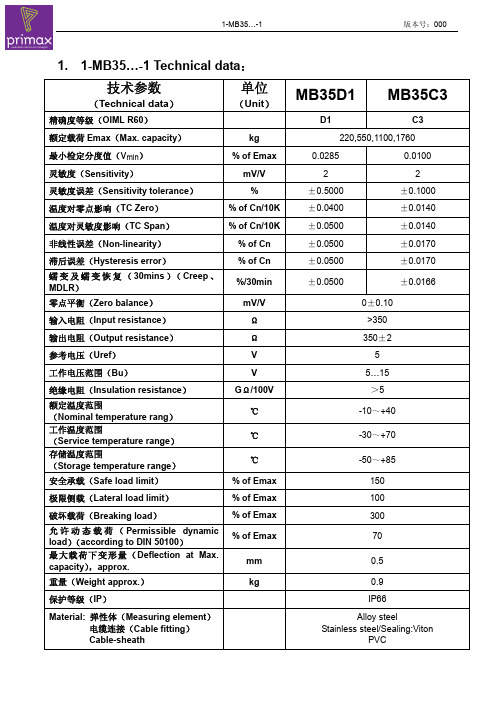
1. 1-MB35…-1 Technical data:技术参数(Technical data)单位(Unit)MB35D1 MB35C3精确度等级(OIML R60)D1C3 额定载荷Emax(Max. capacity) kg 220,550,1100,1760最小检定分度值(v min)% of Emax 0.0285 0.0100灵敏度(Sensitivity) mV/V2 2灵敏度误差(Sensitivity tolerance) % ±0.5000 ±0.1000温度对零点影响(TC Zero)% of Cn/10K±0.0400 ±0.0140温度对灵敏度影响(TC Span)% of Cn/10K±0.0500 ±0.0140非线性误差(Non-linearity)% of Cn±0.0500 ±0.0170滞后误差(Hysteresis error)% of Cn±0.0500 ±0.0170蠕变及蠕变恢复(30mins)(Creep、MDLR)%/30min±0.0500 ±0.0166零点平衡(Zero balance) mV/V0±0.10输入电阻(Input resistance)Ω >350输出电阻(Output resistance)Ω 350±2参考电压(Uref) V5工作电压范围(Bu)V 5 (15)绝缘电阻(Insulation resistance)GΩ/100V>5额定温度范围(Nominal temperature rang)℃ -10~+40工作温度范围(Service temperature range)℃ -30~+70存储温度范围(Storage temperature range)℃ -50~+85安全承载(Safe load limit)% of Emax 150极限侧载(Lateral load limit)% of Emax 100破坏载荷(Breaking load)% of Emax 300允许动态载荷(Permissible dynamicload)(according to DIN 50100)% of Emax 70最大载荷下变形量(Deflection at Max.capacity),approx.mm 0.5重量(Weight approx.) kg 0.9保护等级(IP)IP66Material: 弹性体(Measuring element)电缆连接(Cable fitting)Cable-sheathAlloy steel Stainless steel/Sealing:VitonPVC2. 1-MB35…-1 Part Number Description Part NumberDescriptionDetailed description1-MB35C3/220KG-1 MB35C3/220kg L/C 2MV/V, C3, M12 THD 1-MB35C3/550KG-1 MB35C3/550kg L/C 2MV/V, C3, M12 THD 1-MB35C3/1.1T-1 MB35C3/1.1T L/C 2MV/V, C3, M12 THD 1-MB35C3/1.76T-1 MB35C3/1.76T L/C 2MV/V, C3, M12 THD 1-MB35D1/220KG-1 MB35D1/220kgL/C 2MV/V, D1, M12 THD 1-MB35D1/550KG-1 MB35D1/550kg L/C 2MV/V, D1, M12 THD 1-MB35D1/1.1T-1 MB35D1/1.1T L/C 2MV/V, D1, M12 THD 1-MB35D1/1.76T-1 MB35D1/1.76TL/C 2MV/V, D1, M12 THD3. 1-MB35…-1 Mounting dimension :Cable:Shielded 4-core round cable(19/0.127mm) with PVC-jacketWiring code:Excitation voltage + : green Signal+:whiteSignal - :red Excitation voltage - :blackShield:Yellow, floating4. label: 4.1 Type labelVmin : XXXSAFE LOAD LIMIT = 150%Class : XXX Emax : XXXCn : X.XXmV/V2004MB35XXX /XXXPart NumberTypeClass Emax Cnvmin1-MB35C3/220KG-1 MB35C3/220kg C3 220kg 2.00mV/V 0.0100% 1-MB35C3/550KG-1 MB35C3/550kgC3 550kg 2.00mV/V 0.0100%1-MB35C3/1.1T-1 MB35C3/1.1t C3 1.1t 2.00mV/V 0.0100% 1-MB35C3/1.76T-1 MB35C3/1.76t C3 1.76t 2.00mV/V 0.0100% 1-MB35D1/220KG-1 MB35D1/220kgD1 220kg 2.00mV/V 0.0285%1-MB35D1/550KG-1 MB35D1/550kg D1 550kg 2.00mV/V 0.0285% 1-MB35D1/1.1T-1 MB35D1/1.1t D1 1.1t 2.00mV/V 0.0285% 1-MB35D1/1.76T-1 MB35D1/1.76t D1 1.76t 2.00mV/V 0.0285%4.2 Serial number labelF.-No.: xxxxxxxx4.3 Individual package labelXXXXXXLOAD CELLF.-No.: xxxxxxxx4.4 Outer package labelOrder P/N Altern P/N Type 1-MB35C3/220KG-1 1-MB35C3/220KG-1 MB35C3/220kg 1-MB35C3/550KG-1 1-MB35C3/550KG-1 MB35C3/550kg 1-MB35C3/1.1T-1 1-MB35C3/1.1T-1 MB35C3/1.1t 1-MB35C3/1.76T-1 1-MB35C3/1.76T-1 MB35C3/1.76t 1-MB35D1/220KG-1 1-MB35D1/220KG-1 MB35D1/220kg 1-MB35D1/550KG-1 1-MB35D1/550KG-1 MB35D1/550kg 1-MB35D1/1.1T-1 1-MB35D1/1.1T-1 MB35D1/1.1t 1-MB35D1/1.76T-1 1-MB35D1/1.76T-1 MB35D1/1.76t 编制:审核:批准:。
Datasheet MLX90614 中文 数据手册 rev008
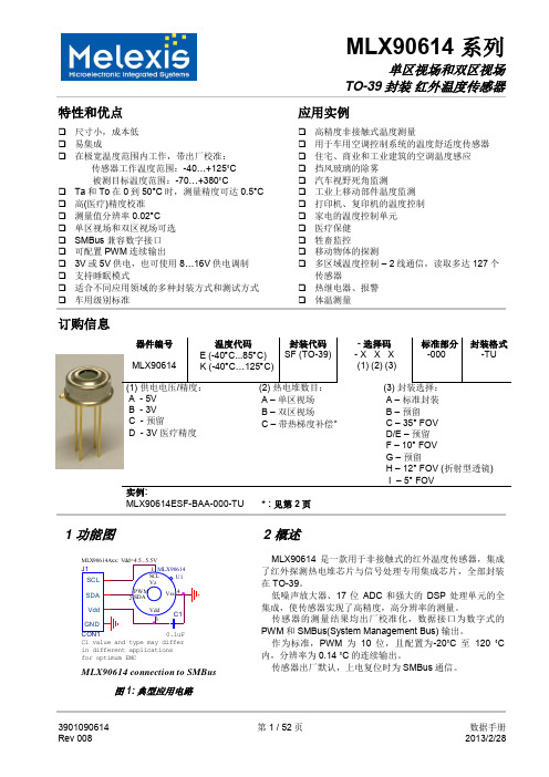
10-位 PWM 输出模式是连续输出所测物体温度的标准配置,测量物体的温度范围为-20…120 °C,分辨 率为 0.14 °C。PWM 通过修改 EEPROM 内 2 个单元的值,实际上可以根据需求调整至任何温度范围,而这对 出厂校准结果并无影响。
传感器的测量结果均出厂校准化,数据接口为数字式的 PWM 和 SMBus(System Management Bus) 输出。
作为标准,PWM 为 10 位,且配置为-20˚C 至 120 ˚C 内,分辨率为 0.14 ˚C 的连续输出。
传感器出厂默认,上电复位时为 SMBus 通信。
3901090614 Rev 008
PWM 引脚也可配置为热继电器(输入是 To),这样可以实现简单且性价比高的恒温控制器或温度报警(冰 点/沸点)应用,其中的温度临界值是用户可编程的。在 SMBus 系统里,这个功能可以作为处理器的中断信号, 以此触发读取主线上从动器的值,并确定精度条件。
传感器有两种供电电压选择:5V 或 3V(电池供电)。其中,5V 也可简便的从更高供电电压(例如 8 至 16V)上通过外接元件调制。(具体请参考“应用信息”)
MLX90614 connection to SMBus
图 1: 典型应用电路
2 概述
MLX90614 是一款用于非接触式的红外温度传感器,集成 了红外探测热电堆芯片与信号处理专用集成芯片,全部封装 在 TO-39。
低噪声放大器、17 位 ADC 和强大的 DSP 处理单元的全 集成,使传感器实现了高精度,高分辨率的测量。
IEC 61400-23:风电叶片测试标准中文讲解

目录前言 (3)引言 (4)1.主题与范围 (5)2.引用标准 (5)3.定义 (5)4.符号 (8)4.1符号 (8)4.2 希腊符号 (8)4.3 下标符号 (8)4.4缩写词 (9)5 通用原则 (9)5.1试验目的 (9)5.2临界状态 (9)5.3实际约束 (10)5.4试验结果 (10)6叶片数据 (11)6.1概要 (11)6.2外部尺寸与接触面 (11)6.3 叶片特性 (11)6.4 材料数据 (12)6.5 设计负荷及条件 (12)6.6试验区域 (13)6.7 特殊的叶片修改 (13)6.8根部固定 (13)6.9机械装置 (13)7.设计和试验负荷条件的不同 (13)7.1 总述 (13)8.试验负荷 (15)8.1总述 (15)8.2 以负荷为基础的试验 (15)8.3以强度为基础的试验 (16)8.4负荷静态试验各方面 (17)8.5负荷疲劳试验各方面 (17)8.6静态和疲劳试验顺序 (18)8.7机械装置 (18)9试验负荷因素 (18)9.1概要 (18)9.2设计中使用的准安全因子 (18)9.3试验负荷因素 (19)9.4负荷系数的应用以获得目标负荷 (20)10 试验负荷分布之于设计负荷的评估 (20)10.1概要 (20)10.2 引入负荷的影响 (20)10.3静态试验 (20)10.4疲劳试验 (22)11故障状态 (24)11.1概要 (24)11.2灾难性故障 (24)11.3功能故障 (24)11.4表面故障 (24)12试验过程和方法 (25)12.1概要 (25)12.2试验台和根部固定装置要求 (25)12.3引入负荷的固定装置第38页图6 (25)12.4静态强度试验 (25)12.5疲劳试验 (26)12.6选择各种试验方法的优缺点 (28)12.7决定性修正 (28)12.8数据收集 (29)13决定叶片性质的其他试验 (30)13.1概要 (30)13.2试验台偏移 (30)13.3偏移 (30)13.4刚度分布 (30)13.5变形分布测量 (31)13.6固有频率 (31)13.7阻尼 (31)13.8形态 (31)13.9(物理)质量分布 (32)13.10蠕变 (32)13.11其他非破坏性试验 (32)13.12叶片分段 (32)14报告 (32)14.1概要 (32)14.2内容 (32)14.2.1通用---所有试验 (32)14.2.2静态试验和疲劳试验 (32)14.2.3其他试验 (33)附录A(常规性)准安全系数的考虑 (34)附录B(常规性)疲劳公式敏感性评估 (35)附录C(常规性)加载角度变化的考虑 (36)附录D(资料性)试验安装实例 (37)Bibliography (39)前言1)IEC(国际电工技术委员会)是由各国家电工技术委员会(IEC国家委员会)组成的世界性标准化组织。
SF304中文资料

SF301 - SF30430A SUPER-FAST RECTIFIERFeatures·Case: TO-3P Molded Plastic·Terminals: Solderable per MIL-STD-202,Method 208·Mounting Position: Any ·Polarity: As marked·Approx. Weight: 5.6 gramMechanical DataMaximum Ratings and Electrical CharacteristicsCharacteristicSymbol SF301SF302SF303SF304Unit Maximum Recurrent Peak Reverse Voltage V RRM 50100150200V Maximum RMS Voltage V RSM 3570105140V Maximum DC Blocking VoltageV DC 50100150200V Maximum Average Forward Rectified Current (Total Device)@ T C = 120°C I (AV)30A Peak forward Surge Current 8.3ms half sine-wave superimposed on rated load (JEDEC Method)I FSM300A Maximum Instantaneous Forward @T J =25°C Voltage per leg at I F = 15A (Note 3)@T J = 150°CV F 0.9750.880V Maximum Instantaneous Reverse Current at @T J =25°C Rated DC Blocking Voltage per leg (Note 3)@T J = 150°C I R 10500m A Typical Junction Capacitance (Note 1)C J 80pF Maximum Reverse Recovery Time (Note 2)T rr 35ns Typical Thermal Resistance, Junction to Case R q JC 1.0°C/W Storage and Operating Temperature RangeT J,T STG-65 to +175°CNotes:(1)Measured at 1MHz and applied reverse voltage of 4.0 volts.(2)Reverse recovery test conditions: I F = +0.5A, I R = 1.0A,di/dt = 50A/m s.(3)Pulse width = 300m S, 2% duty cycle.Rating at 25°C ambient temperature unless otherwise specified.Single phase, half wave, 60Hz, resistive or inductive load.For capacitive load, derate current 20%.TO-3PDim Min Max A 3.2 3.5B4.55.4C 21.622.5D 18.921.7E 2.4 2.8G 0.550.81H15.816.2J 1.7 2.7K 3.1Ø 3.3ØL4.2 4.5M5.1 5.7N 0.89 1.5P 2.9 3.3R 11.712.8S5.06.0A BEGJ LMNP K S MHRDCCommon Cathode (no Suffix) shown Add Suffix ‘A’ for Common Anode & change ‘+’ to ‘-’ in illustration above·Plastic Package - UL Flamability Classification 94V-0·High Current Capability ·High Surge Capacity·High Fast Switching Capability < 35 ns ·Low Switching Noise and High ReliabilityI ,A V E R A G E F W D R E C T I F I E D C U R R E N T (A )A V 25507510012515005101520TEMPERATURE (°C)Fig.1,T ,Forward Current Derating CurveC 11010050100150200250300350400NUMBER OF CYCLES AT 60Hz Fig.4Peak Forward Surge CurrentI ,P E A K F W D S U R G E C U R R E N T (A )F S M 110100V ,REVERSE VOLTAGE (VOLTS)Fig.3Typical Junction CapacitanceR 101001000C ,J U N C T I O N C A P A C I T A N C E (p F )J 00.40.81.2 1.62.00.11.010100V ,INSTANTANEOUS FORWARD VOLTAGE (VOLTS)Fig.2Typical Forward CharacteristicsF I ,I N S T A N T A N E O U S F W D R E C T I F I E D C U R R E N T (A )P e r L e gF40801601202000.010.11.010V ,REVERSE VOLTAGE (VOLTS)Fig.5,Typical Reverse CharacteristicsR I ,I N S T A N T A N E O U S R E V E R S E C U R R E N T (µA )R -1.0A-0.25A+0.5A10W Non Inductive50W Non Inductive Notes:1.Rise Time =7ns max,nce =1MW 22pF2.Rise Time =10ns max Source Impedence =50W。
脱硫系统中英文对照表
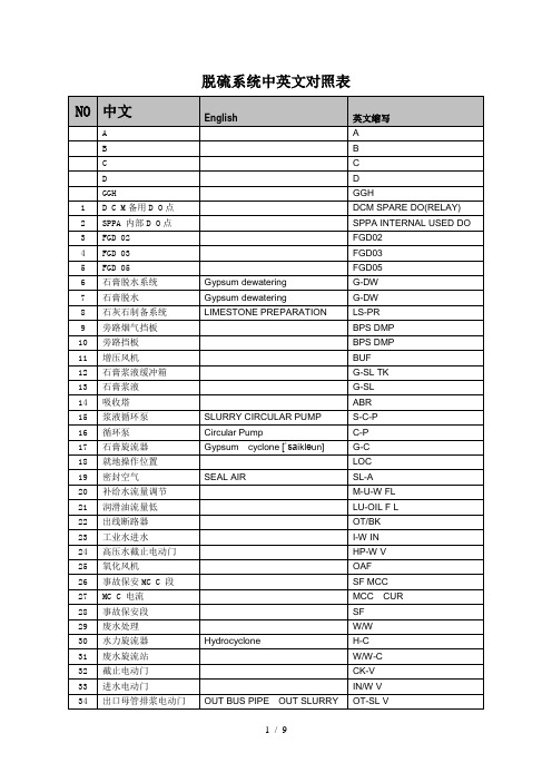
48
石灰石制备
LS-PR
49
排水坑
DRN PIT
50
自引罐
self priming
SEF
51
自引灌
self priming
SEF
52
搅拌器电机
AGR
53
低泄露风机电机
L-LK FAN
54
取样系统
SAMPLING SYSTEM
SM-S
55
事故浆液箱
EM SL TK
56
事故浆液
EM SL
57
氧化空气
180
传感器
transmitter
TSMR
181
油站
OIL ST
182
备用泵
STANDBY PUMP
S-PU
183
电加热器
HTR
184
加热器
HTR
185
超温报警
T-ALM
186
吹灰器
SO-BLWR
187
推进状态
ENGED
188
退出状态
EXTACED
189
推进指令
ENGE
190
退出指令
EXTAC
191
S-C-P
16
循环泵
Circular Pump
C-P
17
石膏旋流器
Gypsum cyclone[ˈsaikləun]
G-C
18
就地操作位置
LOC
19
密封空气
SEAL AIR
SL-A
20
补给水流量调节
M-U-W FL
21
润滑油流量低
LU-OIL F L
SF5G资料

Maximum Ratings and Electrical Characteristics
0.95
1.27 5.0 400.0 35.0 22.0 50.0 -55 to +150
1.75
Volts A A nS F /W
TJ, TSTG
Notes: (1) Reverse recovery test conditions: IF=0.5A, IR=1.0A, Irr=0.25A (2) Measured at 1.0MHz and applied reverse voltage of 4.0 VDC (3) Thermal resistance from junction to ambient and from junction to lead length 0.375 (9.5mm) P.C.B. mounted
VRRM VRMS VDC I(AV) IFSM VF IR IR Trr CJ R
JA
50 35 50
100 70 100
200 140 200
400 280 400 1.0 30.0
600 420 600
800 560 800
1000 700 1000
Volts Volts Volts Amp Amps
Mechanical Data
Case: Molded plastic, A-405 Terminals: Axial leads, solderable to MIL-STD-202, method 208 Polarity: Color band denotes cathode end Mounting Position: Any Weight: 0.008 ounce, 0.235 gram
赛门铁克产品中文知识库文档列表
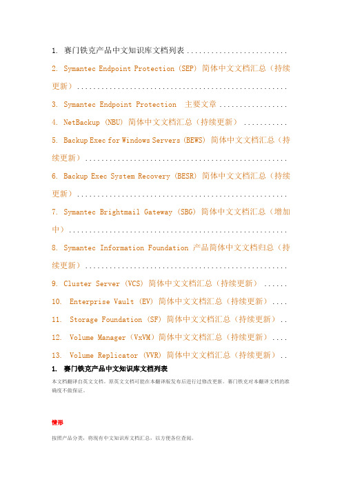
1. 赛门铁克产品中文知识库文档列表.........................2.Symantec Endpoint Protection (SEP) 简体中文文档汇总(持续更新)....................................................3.Symantec Endpoint Protection 主要文章.................Backup (NBU) 简体中文文档汇总(持续更新) ...........5.Backup Exec for Windows Servers (BEWS) 简体中文文档汇总(持续更新)..................................................6.Backup Exec System Recovery (BESR) 简体中文文档汇总(持续更新)....................................................7.Symantec Brightmail Gateway (SBG) 简体中文文档汇总(增加中)......................................................8.Symantec Information Foundation 产品简体中文文档归总(持续更新)..................................................9.Cluster Server (VCS) 简体中文文档汇总(持续更新) ......10.Enterprise Vault (EV) 简体中文文档汇总(持续更新)....11.Storage Foundation (SF) 简体中文文档汇总(持续更新)..12.Volume Manager(VxVM)简体中文文档汇总(持续更新)....13.Volume Replicator (VVR) 简体中文文档汇总(持续更新)..1.赛门铁克产品中文知识库文档列表本文档翻译自英文文档。
SFF-协议中文

编号:_______________本资料为word版本,可以直接编辑和打印,感谢您的下载SFF-协议中文甲方:___________________乙方:___________________日期:___________________此文档用于看英文文档的参照,并非〈〈SFF -8472 Rev 10.1 »所有内容均被翻译(当然没有翻译的地方我作了注释啦)。
精选范本范围和概述W前是关于版本号等一些描述性的东西,不做翻译这个文件定义了一个带有数字诊断接口的增强型的内存表,数字诊断接口是为收发机服务的,这可以让虚实时系统能够获得设备的测量参数。
它同样加入了新的选项到先前定义的两线的存储表中,以便于兼容新的SFPMS成者GBICC件的收发器类型。
接口是一个在GBI俄者SFPMS硕明书中定义的两线的接口ID的扩展。
两个说明书定义的25鲜节的存储表可以通过串行的两线接口在8位的地址结构1010000XA0h处得到访问。
数字诊断监控接口利用的是8位的地址1010001XA2h ,这样原始定义的两线的接口ID存储表就可以保持不变。
这些接口既向后兼容GBITX兼容SFPMSA可应用的文件GigabitInterfaceConverte(GBIC).SFF documentiumber:SFF-8053rev. 5.5, Septemb27,2000. SmalFormFactoPluggablebFPTransceivSiFFdocumemtumbeIrNF-8074^v.1.0,May122001(BasedntheinitiaSeptembe4,2001MS/publicelease).SFPRateandApplicati(SelectioSFFdocume n timbeBFF-8079v1.7,February 2,2005. SFPRateanclApplicatiOnodeSSFFdocume n tmbe^BFF-8089!v1.3,Februa3/; 2005.Enhanced5and10GigabSmalFornFactoPluggabModuieSFPP|us). SFFdocume n tjmbe{BFF-843rfe;v1.6,Decemb21,2006. 增强的数字诊断接口定义概述增强数字诊断接口是一个在200评9月14日的SFPMSA^件数据定义的MOD_DEF接口,之后,遵从了SF成员会后变成了INF-8074^及两线的接口的定义、硬件、和时序都在这里被清晰的定义了。
中文车型对照表
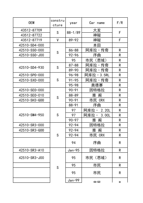
97-00 95-98 93-95 94-95 92-96 93-96 98-99 Jan-98 98-00 Jan-98 98-99 94-95 96-99 94-95 Jan-96 96-99 Jan-94 96-99 96-99 8512/86 1/87-89 89-93 88-95 88-91 89-93 88-95 91-92 93-95 87-91
constru cture S V S
year 88-1/89 89-92 86-88 92-96 95 87-88 89-90 96-98 91-95 95-98 90-91 88-89 90-91 88-91 97 97 90-97 92-94 92-94 92-94 94
Car name 大发 神秘 神秘 本田 阿库拉·传奇 序曲 市民(思域) 阿库拉·传奇 阿库拉·传奇 阿库拉·3.5RL 阿库拉·传奇 奥德赛 因特格拉 雅 阁 市民 CRX 序曲 阿库拉· 2.2CL 阿库拉· 3.0CL 雅 阁 因特格拉 雅 阁 市民 CRX 序曲 因特格拉 市民(思域) 市民 市民 市民
本 田CR-V 奥德赛 阿库拉·传奇 阿库拉·传奇 序 曲 序 曲 阿库拉 2.3CL 雅 阁 雅 阁 雅 阁 阿库拉 3.0 CL
F F F F F F F F R F F F F F F R R R F F F R R R F F F F F
阿库拉 SLX 阿库拉 SLX 五十铃 沙漠王 沙漠王 艾·马克 艾·马克 AMIGO 五十铃皮卡 骑兵Ⅱ型 五十铃皮卡 赛马 赛马 骑兵Ⅱ型
V
8-94375-533-3 8-97034-035-3 8-97034-053-3 8-97096-395-0
V
8-94387-590-0 8-94387-591-0 8-94387-591-1
F-35B 的垂直升力系统

F-35B 的垂直升力系统概念上很简单,但是魔鬼存在于细节之中,F-35B 的实际研发过程是困难重重。
F-35B 的垂直升力系统用一根传动轴将主发动机部分功率传递到座舱后的升力风扇,升力风扇与可向下转向95 度,转到垂直状态的主发动机尾喷管协力,像抬轿子一样,把飞机抬起来。
升力风扇的举升力为89 千牛,主发动机的垂直推力为80 千牛,像两只小手臂般从发动机向两侧伸出的姿态控制喷管各产生8.7 千牛推力,总垂直升力为186 千牛。
由于F-35B 的空重已经达到14500 千克,垂直降落时能携带的燃油储备和未用完弹药的重量就受到很大限制。
由于F-35B 的航电冷却系统依赖燃油系统作为热汇,燃油储备太低时冷却功率就不够,因此环境温度高时垂直降落状态航电可能无法可靠工作。
F-35B 的垂直升力设计与X-32 或“鹞” 的相比,能以同等驱动功率加速更大空气流量,能在发动机不开加力情况下产生与加力推力相当的垂直推力,而且发动机对地面/甲板产生的热压力相对较小,发动机也不易吸入影响功率的高温排气流。
主发动机可转向尾喷管必须在 2.5 秒内旋转95 度,同时要承受高达80 千牛的推力以及巨大的热量和振动,对机械性能的要求是非常高的,因此使用的是造价高昂的钛合金结构。
姿态控制喷管如果工作时间太长会造成其旋转做动器的过热,因此F-35B 不能维持太长时间的垂直盘旋状态。
垂直升力系统传动轴以每分钟8000 转的转速传递29000 马力的轴功率,是开天辟地以来功率密度最大的机械传动部件,垂直升力系统的关键组成部分。
解决传动轴的振动问题费了研发团队不少的脑细胞。
最大的工程挑战还是来自在战斗机狭小的空间内输出与中国052 系列驱逐舰主轴功率相当的巨大驱动力的升力风扇系统。
升力风扇的直径是1.27 米,对F-35 系列肥胖的外形有不小的“贡献”。
离合器的体积和重量受到战斗机使用的限制,有非常严格的上限,然而却必须在9-12 秒内将风扇从静止加速到29000 轴马力,需要承受的机械负荷可以用恐怖来形容,在工作过程中产生的热量也非常巨大,依靠流量大约每秒 2 升的油冷系统加以控制。
(完整版)SF-36评分标准

F -36计分说明1. SF -36的内容与结构2. SF -36计分方法:2.1 基本步骤2.2 关于缺失值的处理2.3 健康状况各方面得分及换算1. SF -36的内容与结构SF -36,健康调查简表(the MOS item short from health survey, SF -36),是在1988年 Stewartse 研制的医疗结局研究量表(medical outcomes study –short from, MOS SF )的基础上,由美国波士顿健康研究发展而来。
1991年浙江大学医学院社会医学教研室翻译了中文版的SF -36。
SF -36是美国波士顿健康研究所研制的简明健康调查问卷,被广泛应用于普通人群的生存质量测定、临床试验效果评价以及卫生政策评估等领域。
SF -36作为简明健康调查问卷,它从生理机能、生理职能、躯体疼痛、一般健康状况、精力、社会功能、情感职能以及精神健康等8个方面全面概括了被调查者的生存质量。
1.1 生理机能(PF :Physical Functioning ):测量健康状况是否妨碍了正常的生理活动。
用第3个问题来询问PF 。
1.2 生理职能(RP :Role -Physical ):测量由于生理健康问题所造成的职能限制。
1.3 躯体疼痛(BP :Bodily Pain ):测量疼痛程度以及疼痛对日常活动的影响。
1.4 一般健康状况(GH :General Health ):测量个体对自身健康状况及其发展趋势的评价。
1.5 精力(VT :Vitality ):测量个体对自身精力和疲劳程度的主观感受。
1.6 社会功能(SF :Social Functioning ):测量生理和心理问题对社会活动的数量和质量所造成的影响,用于评价健康对社会活动的效应。
1.7 情感职能(RE :Role -Emotional ):测量由于情感问题所造成的职能限制。
化妆品用原料INCI中文名称大全
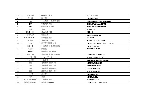
四一(二丁基羟基氢化肉桂酸)季戊四醇酯
TETRADIBUTYLPENTAERITHRITYL
HYDROXYHYDROCIMNAMATE
84
CAB
椰油酰胺丙基甜菜碱
COCAMIDOPROPYL BETAINE
85
GM—2002硅油
聚二甲基硅氧烷 聚二甲基硅烷醇C12烷基磺酸铵
86
QE—22
油醇聚氧乙烯醚一22
序CI英文名称
1
丙二醇
丙二醇
PROPANEDIOI
2
1831
十八烷基三甲基氯化铵
STEARTRIMONIUM CHLORIDE
3
IPP
棕榈酸异丙酯
ISOPROPYL PALMITATE
4
IPM
肉豆蔻酸异丙酯
ISOPROPYL MYRISTATE
5
甘油
甘油
GLYCERIN
76
SCI—65
椰油酰羟乙磺酸酯钠
SODIYM COCOYL ISETHIONATE
77
CMEA
椰油酰胺MEA
COCAMIDE MEA
78
瓜耳胶
瓜耳胶羟丙基三甲基氯化铵
GUARHYDROXYPROPYLTRIMONIUM
CHLORIDE
79
1000NI
鲸蜡硬脂醇和鲸蜡硬脂醇聚醚一20
CETEARTL ALCOHOL(AND)CETEARETH—20
24
氢氧化钾(KOH)
氢氧化钾(KOH)
POTASSIUM HYDROXIDE
序号
现用名称
INCI中文名称
INCI英文名称
25
C12酸
月桂酸
F-35“闪电”Ⅱ战斗机

F-35“闪电”Ⅱ战斗机F-35“闪电”Ⅱ战斗机F-35“闪电”Ⅱ(Lightning Ⅱ)战斗机是由美国洛克希德·马丁公司设计及生产的单座单发战斗攻击机,分为传统跑道起降的F-35A 型、短距离起降/垂直起降的F-35B型和航空母舰舰载机F-35C型。
武器点评F-35属于具有隐身设计的第五代战斗机,具备有限的超音速巡航能力,它将是美国和其盟国在21世纪的空战主力。
历史回顾F-35战斗机源于美军的联合打击战斗机计划(Joint Strike Fighter Program,简称JSF),洛克希德·马丁公司的X-35原型机击败波音公司的X-32原型机,获得了JSF计划的竞标。
在经过各阶段试验后,JSF计划于2001年10月26日正式进入了系统开发试验阶段。
JSF有三个型号,空军陆上型F-35A于2006年12月15日首飞,陆战队垂直起降型F-35B于2008年6月11日首飞,海军舰载型F-35C 于2010年6月6日首飞。
F-35C预计于2018年开始服役,将装备“福特”级航空母舰。
主要结构F-35战斗机的外形很像F-22战斗机的单发动机缩小版,其隐身设计借鉴了F-22战斗机的很多技术与经验。
F-35战斗机采用古德里奇公司为其量身定制的起落架系统,配备固特异公司制造的“智能”轮胎,轮胎中内置了传感器和发射装置,可以监测胎压、胎温。
综合性能F-35在战机世代上属于第五代战斗机,具备较高的隐身设计、先进的电子系统以及一定的超音速巡航能力。
F-35虽然被定义为F-22的低阶辅助机种,但由于较后研制的原因,一些设计比F-22更加合理,电子设备也更为先进,如F-35是第一款用头盔显示器完全替代抬头显示器的战斗机。
该机装有一门25 毫米GAU-12/A“平衡者”机炮,还可以挂载AIM-9X、AIM-120、AGM-88、AGM-154、AGM-158、海军打击导弹、远程反舰导弹等多种导弹武器,并可使用多种炸弹和核弹,火力十分强劲。
F-35战斗机 详细资料

F-35联合攻击战斗机(JSF)是美国准备在21世纪使用的主力战斗机之一。
计划取代美空军的F-15E、F-16、A-10和F-117,海军的F-14、海军陆战队的AV-8B,英海军的“海鹞”式和空军的“狂风”、“鹞”式等飞机。
1999年首飞。
1996年JSF美国国防部项目刚招标时,只有麦道公司、诺斯罗普·格鲁曼公司和洛克希德·马丁公司(Lockheed Martin Aeronautics Company)三大航空集团提出方案,后来增加了波音公司。
美军方经过审查决定由波音公司和洛克希德·马丁公司各自研制2架验证机,编号分别为X-32和X-35。
2001年10月26日,美国国防部空军部长罗希宣布根据实力、设计的优缺点以及风险程度,洛克希德·马丁公司的X-35方案最终战胜了强有力的竞争对手波音公司的X-32方案,赢得了有史以来最大的军火合同,负责研制开发下一代先进联合攻击战斗机,也就是JSF(Joint Strike Fighter),新一代的联合攻击战斗机也被正式定名为F-35。
F-35洛克希德·马丁公司制造,其合作团队包括:诺斯罗普·格鲁门公司(Northrop Grumman),普拉特和惠特尼(Pratt and Whitney)公司,罗尔斯罗伊斯(Rolls-Royce)公司,埃里森(Allison)公司和BAE系统公司。
先进的电子探测阵列雷达由诺斯罗普·格鲁曼公司生产,电子对抗设备由桑德思公司和利顿公司提供。
光电寻的系统由洛克希德·马丁导弹与火控公司生产。
热成像系统由诺斯罗普·格鲁门公司制造。
先进的头盔显示系统由以色列的凯瑟电子公司承办。
JSF计划要求新一代的多功能多角色战斗机提出了很高的要求。
总体说来它必须具备良好的对地攻击能力,同时兼顾对空作战能力;它必须符合美国空军、海军、海军陆战队及其盟国的需要;它必须具备较强的生存能力和隐身性能、精确的攻击能力以及较低的造价。
- 1、下载文档前请自行甄别文档内容的完整性,平台不提供额外的编辑、内容补充、找答案等附加服务。
- 2、"仅部分预览"的文档,不可在线预览部分如存在完整性等问题,可反馈申请退款(可完整预览的文档不适用该条件!)。
- 3、如文档侵犯您的权益,请联系客服反馈,我们会尽快为您处理(人工客服工作时间:9:00-18:30)。
VOLTAGE RANGE 50 to 600 Volts CURRENT 3.0 Ampere
MAXIMUM RATINGS (@ T A =25 O C unless otherwise noted)
ELECTRICAL CHARACTERISTICS (@T A =25 O C unless otherwise noted)
RATINGS
Maximum Recurrent Peak Reverse Voltage Maximum RMS Voltage Maximum DC Blocking Voltage
Maximum Average Forward Rectified Current at T A = 55o C
Peak Forward Surge Current 8.3 ms single half sine-wave superimposed on rated load (JEDEC method)Typical Thermal Resistance (Note 3)Typical Junction Capacitance (Note 2)SYMBOL V RRM V DC I FSM C J T J , T STG
V RMS UNITS Volts Volts Amps 3.01258.0
2050
Amps
C/W 0
C
Operating and Storage Temperature Range
R q JL R q JA I O -55 to + 150
pF
Volts 30
100300150SF31SF33SF35SF32SF34200400SF3650100
300
150
200400
50
7021010514028035600SF37600
420NOTES : 1. Test Conditions: I F = 0.5A, I R = -1.0A, I RR = -0.25A
2. Measured at 1 MHz and applied reverse voltage of 4.0 volts.
3. Typical Thermal Resistance : At 9.5mm lead lengths,PCB mounted.
4. "Fully ROHS complaint", "100% Sn plating (Pb-free)"
2006-11 REV:B
CHARACTERISTICS
at Rated DC Blocking Voltage
Maximum Reverse Recovery Time (Note 1)V F SYMBOL
I R nSec m Amps
Maximum DC Reverse Current Maximum Instantaneous Forward Voltage at 3.0A DC Volts 5.035
@T A = 100o C
@T A = 25o
C trr
0.95
1.25
10050UNITS SF31SF33SF35
SF32SF34SF36SF371.50
DO-201AD
AMBIENT TEMPERATURE, (O C)I N S T A N T A N E O U S R E V E R S E C U R R E N T , (m A )
RATING AND CHARACTERISTICS CURVES ( SF31 THRU SF37 )
FIG.2 TYPICAL FORWARD CURRENT DERATING CURVE
FIG.1 TEST CIRCUIT DIAGRAM AND REVERSE RECOVERY TIME CHARACTERISTIC
PERCENT OF RATED PEAK REVERSE VOLTAGE, (%)
A V E R A G E F O R W A R D C U R R E N T , (A )
FIG.3 TYPICAL REVERSE CHARACTERISTICS
50 W
10 W
SET TIME BASE FOR 50/100 ns/cm
1 megohm. 22pF.
2. Rise Time = 10ns max. Source Impedance = 50 ohms.
NUMBER OF CYCLES AT 60Hz
P E A K F O R W A R D S U R G E C U R R E N T , (A )
INSTANTANEOUS FORWARD VOLTAGE, (V)
10
3020
50100
200I N S T A N T A N E O U S F O R W A R D C U R R E N T , (A )
1.00.30.10.03
0.01
3.0
1020
RATING AND CHARACTERISTICS CURVES ( SF31 THRU SF37 )
FIG.4 TYPICAL INSTANTANEOUS FORWARD CHARACTERISTICS
FIG.5 MAXIMUM NON-REPETITIVE FORWARD SURGE CURRENT
REVERSE VOLTAGE, (V)
J U N C T I O N C A P A C I T A N C E , (p F )
464020106020010021FIG.6 TYPICAL JUNCTION CAPACITANCE
Rectron Inc reserves the right to make changes without notice to any product
specification herein, to make corrections, modifications, enhancements or other changes. Rectron Inc or anyone on its behalf assumes no responsibility or liabi- lity for any errors or inaccuracies. Data sheet specifications and its information contained are intended to provide a product description only. "Typical" paramet- ers which may be included on RECTRON data sheets and/ or specifications ca- n and do vary in different applications and actual performance may vary over ti- me. Rectron Inc does not assume any liability arising out of the application or use of any product or circuit.
Rectron products are not designed, intended or authorized for use in medical, life-saving implant or other applications intended for life-sustaining or other rela- ted applications where a failure or malfunction of component or circuitry may di- rectly or indirectly cause injury or threaten a life without expressed written appr- oval of Rectron Inc. Customers using or selling Rectron components for use in such applications do so at their own risk and shall agree to fully indemnify Rect- ron Inc and its subsidiaries harmless against all claims, damages and expendit- ures.
DISCLAIMER NOTICE。
