PD438B-C1中文资料
dmp324c1站用变保护测控装置说明书_v2.0
(v2-2013)
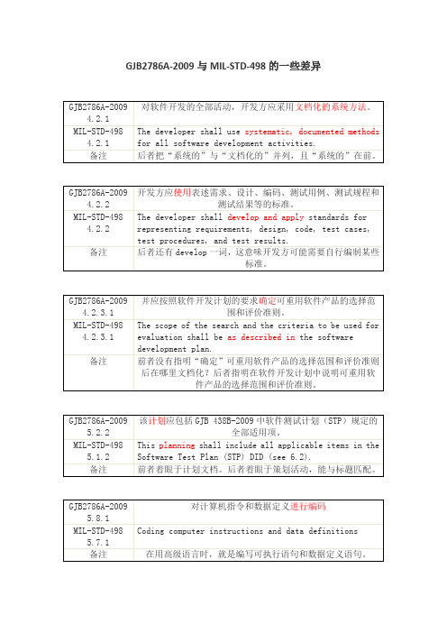
GJB438B学习笔记
与新的系统或修改系统相比,简述现行系统存在的差距。
备注
将在第5章描述新系统或修改后系统,此时还不好与之相比。按前者理解为“简述现行系统或状况不能满足上述新建或修改的因素的短缺或局限”。
1994年12月5日批准的DI-IPSC-81430已被2000年1月10日批准的DI-IPSC-81430A替代。以下列出笔者找到的差异。
GJB2786A-2009
5.10.2
在目标计算机系统上进行测试
CSCI合格性测试应在目标计算机系统或在需方批准的替代系统上进行。
MIL-STD-498
5.9.2
Testing on the target computer system.
CSCI qualification testing shallincludetesting on the target computer system or an alternative system approved by the acquirer.
GJB438B-2009附录A 3.4
本条应描述现行系统用户的类型和当前状态下所涉及到的人员。
备注
根据前者以及后者第3章,应理解为“或当前状况”。
DI-IPSC-81430 4.1b
Summarize deficiencies or limitations in the current system or situation that make it unable to respond to these factors.
备注
后者还有develop一词,这意味开发方可能需要自行编制某些标准。
GJB2786A-2009
4.2.3.1
三极管参数

SHENZHEN HIGHFOUND CO., LTD
摘要
恒丰德公司 WINSEMI 产品线 产品特性 抗冲击特性比较 导通压降特性比较 SCR特性比较 MCR温度特性曲线 BJT的开关时间比较 可靠性测试标准
2
WINSEMI产品线
3
WINSEMI产品
Power BJT 分离式 功率器件产品线
漏极电流ID
漏源极电压VDS
VV X10= VDS
注:其中有几颗常规料沿袭了IR公司的编码如:640(18N20); 730(6N40); 740(10N40); 830(5N50); 840(8N50); 3710(59N10)
10
POWER MOSFET-功率场效应管(1)
11
POWER MOSFET-功率场效应管(2)
TO202-3
TO126 TO252
TO220Insulated
Z0405MF
TO220
WTPA12A60TW STPB12A60TW
TO220Insulated TO220
BTA12-600TW BTB12-600TW MAC12-8FP BTA212-600E
注: ST尾缀 S<5mA; T<10mA; B<35mA; C<50mA PHI尾缀 D<5mA; E<10mA; F<25mA; 空<35mA; G<50mA
It gives : a narrow current gain to minimize asymmetry switching which induce device to destruct. 较小的电流增益使开关电源的不对称减到最小。 a wide forward biased SOA and reverse biased SOA. a enhanced switching speed and low dynamic Vce(sat) which makes system efficiency high. 更快的交换速度以及稳定的集电极-发射极电压,使系统效率更高,更稳定
CD4528BCM中文资料

© 2004 Fairchild Semiconductor Corporation DS005998October 1987Revised January 2004CD4528BC Dual Monostable MultivibratorCD4528BCDual Monostable MultivibratorGeneral DescriptionThe CD4528BC is a dual monostable multivibrator. Each device is retriggerable and resettable. Triggering can occur from either the rising or falling edge of an input pulse,resulting in an output pulse over a wide range of widths.Pulse duration and accuracy are determined by external timing components Rx and Cx.Featuress Wide supply voltage range: 3.0V to 18V s Separate reset availables Quiescent current = 5.0 nA/package (typ.) at 5.0 V DC s Diode protection on all inputss Triggerable from leading or trailing edge pulses Capable of driving two low-power TTL loads or one low-power Schottky TTL load over the rated temperature rangeOrdering Code:Connection Diagram Top ViewTruth TableH = HIGH Level L = LOW Level↑ = Transition from LOW-to-HIGH ↓ = Transition from HIGH-to-LOW = One HIGH Level Pulse = One LOW Level Pulse X = IrrelevantOrder Number Package NumberPackage DescriptionCD4528BCM M16A 16-Lead Small Outline Integrated Circuit (SOIC), JEDEC MS-012, 0.150" Narrow CD4528BCNN16E16-Lead Plastic Dual-In-Line Package (PDIP), JEDEC MS-001, 0.300" WideInputsOutputsClear A B Q Q L X X L H X H X L H X X LLHH L↓ H↑H 2C D 4528B CBlock DiagramLogic Diagram(½ of Device Shown)Note : Externally ground pins 1 and 15 to pin 8.CD4528BCAbsolute Maximum Ratings (Note 1)(Note 2)Recommended Operating Conditions (Note 2)Note 1: “Absolute Maximum Ratings” are those values beyond which the safety of the device cannot be guaranteed. Except for “Operating Tempera-ture Range”, they are not meant to imply that the devices should be oper-ated at these limits. The table of “Electrical Characteristics” provides conditions for actual device operation.Note 2: V SS = 0V unless otherwise specified.DC Electrical Characteristics (Note 3)Note 3: V SS = 0V unless otherwise specified.Note 4: I OH and I OL are tested one output at a time.DC Supply Voltage (V DD )−0.5 V DC to +18 V DC Input Voltage, All Inputs (V IN )−0.5 V DC to V DD +0.5 V DCStorage Temperature Range (T S )−65°C to +150°CPower Dissipation (P D )Dual-In-Line 700 mW Small Outline 500 mWLead Temperature (T L )(Soldering, 10 seconds)260°C DC Supply Voltage (V DD )3V to 15V Input Voltage (V IN )0V to V DD V DCOperating Temperature Range (T A )−55°C to +125°CSymbol ParameterConditions−55°C +25°C +125°C UnitsMinMax MinTyp Max MinMax I DDQuiescent Device CurrentV DD = 5V 50.0055150µAV DD = 10V 100.01010300V DD = 15V200.01520600V OLLOW Level Output VoltageV DD = 5V 0.050.050.05VV DD = 10V 0.050.050.05V DD = 15V0.050.050.05V OHHIGH Level Output VoltageV DD = 5V 4.95 4.95 5.0 4.95VV DD = 10V 9.959.9510.09.95V DD = 15V14.9514.9515.014.95V ILLOW Level Input VoltageV DD = 5V, V O = 0.5V or 4.5V 1.5 2.25 1.5 1.5VV DD = 10V, V O = 1V or 9V 3.0 4.50 3.0 3.0V DD = 15V, V O = 1.5V or 13.5V4.06.75 4.04.0V IHHIGH Level Input VoltageV DD = 5V, V O = 0.5V or 4.5V 3.5 3.5 2.75 3.5VV DD = 10V, V O = 1V or 9V 7.07.0 5.507.0V DD = 15V, V O = 1.5V or 13.5V11.011.08.2511.0I OLLOW Level Output Current V DD = 5V, V O = 0.4V 0.640.510.880.36mA(Note 4)V DD = 10V, V O = 0.5V 1.6 1.3 2.250.9V DD = 15V, V O = 1.5V 4.2 3.48.8 2.4I OHHIGH Level Output Current V DD = 5V, V O = 4.6V −0.25−0.2−0.36−0.14mA(Note 4)V DD = 10V, V O = 9.5V −0.62−0.5−0.9−0.35V DD = 15V, V O = 13.5V −1.8−1.5−3.5−1.1I INInput CurrentV DD = 15V, V IN = 0V −0.1−10−5−0.1−1.0µAV DD = 15V, V IN = 15V0.110−50.1 1.0 4C D 4528B CAC Electrical Characteristics (Note 5)T A = 25°C, C L = 50 pF, R L = 200 k Ω, Input t r = t f = 20 ns, unless otherwise specified Note 5: AC parameters are guaranteed by DC correlated testing.Symbol ParameterConditionsMinTyp Max Unitst rOutput Rise Timet r = (3.0 ns/pF) C L + 30 ns, V DD = 5.0V 180400ns t r = (1.5 ns/pF) C L + 15 ns, V DD = 10.0V 90200t r = (1.1 ns/pF) C L + 10 ns, V DD = 15.0V65160t fOutput Fall Timet f = (1.5 ns/pF) C L + 25 ns, V DD = 5.0V 100200ns t f = (0.75 ns/pF) C L + 12.5 ns, V DD = 10V 50100t f = (0.55 ns/pF) C L + 9.5 ns, V DD = 15.0V3580t PLH Turn-Off, Turn-On Delay t PLH , t PHL = (1.7 ns/pF) C L + 240 ns, V DD = 5.0V 230500ns t PHLA orB to Q or Q t PLH , t PHL = (0.66 ns/pF)C L + 8 ns, V DD = 10.0V 100250Cx = 15 pF, Rx = 5.0 k Ωt PLH , t PHL = (0.5 ns/pF) C L + 65 ns, V DD = 15.0V 65150Turn-Off, Turn-On Delay t PLH , t PHL = (1.7 ns/pF) C L + 620 ns, V DD = 5.0V 230500ns A or B to Q or Q t PLH , t PHL = (0.66 ns/pF) C L + 257 ns, V DD = 10.0V 100250Cx = 100 pF, Rx = 10 k Ωt PLH , t PHL = (0.5 ns/pF) C L + 185 ns, V DD = 15.0V 65150t WL Minimum Input Pulse Width V DD = 5.0V 60150ns t WHA or BV DD = 10.0V 2050Cx = 15 pF, Rx = 5.0 k ΩV DD = 15V 2050Cx = 1000 pF, Rx = 10 k ΩV DD = 5.0V 60150ns V DD = 10.0V 2050V DD = 15.0V2050PW OUTOutput Pulse Width Q or Q V DD = 5.0V 550nsFor Cx < 0.01 µF (See Graph V DD = 10.0V 350for Appropriate V DD Level)Cx = 15 pF, Rx = 5.0 k ΩV DD = 15.0V 300For Cx > 0.01 µF Use V DD = 5.0V 152945µs PW out = 0.2 Rx Cx In [V DD − V SS ]V DD = 10.0V103790Cx = 10,000 pF, Rx = 10 k ΩV DD = 15.0V 154295t PLH Reset Propagation Delay,V DD = 5.0V 325600ns t PHLt PLH , t PHLV DD = 10.0V 90225Cx = 15 pF, Rx = 5.0 k ΩV DD = 15.0V 60170Cx = 1000 pF, Rx = 10 k ΩV DD = 5.0V 7.0µsV DD = 10.0V 6.7V DD = 15.0V6.7t RRMinimum Retrigger Time V DD = 5.0V 0ns Cx = 15 pF, Rx = 5.0 k ΩV DD = 10.0V 0V DD = 15.0V 0Cx = 1000 pF, Rx = 10 k ΩV DD = 5.0V 0V DD = 10.0V 0V DD = 15.0V0Pulse Width Match between Circuits V DD = 5.0V 625%in the Same Package V DD = 10.0V 835Cx = 10,000 pF, Rx = 10 k ΩV DD = 15.0V835CD4528BCPulse WidthsFIGURE 1. Pulse Width vs CxFIGURE 2. Normalized Pulse Width vs Temperature 6C D 4528B CAC Test Circuits and WaveformsDuty Cycle = 50%FIGURE 3. Power Dissipation Test Circuit and Waveforms*Includes capacitance of probes, wiring, and fixture parasitic.Note: AC test waveforms for PG1, PG2, and PG3 in Figure 4.Input ConnectionsFIGURE 4. AC Test CircuitCharacteristics C D A B t PLH , t PHL , t r , t f ,V DDPG1V DDPW out , PW in t PLH , t PHL , t r , t f ,V DDV SSPG2PW out , PW int PLH(R), t PHL(R), PW inPG3PG1PG2CD4528BC AC Test Circuits and Waveforms (Continued)FIGURE 5. AC Test Waveforms 8C D 4528B CPhysical Dimensionsinches (millimeters) unless otherwise noted16-Lead Small Outline Integrated Circuit (SOIC), JEDEC MS-012, 0.150" NarrowPackage Number M16A9CD4528BC Dual Monostable MultivibratorPhysical Dimensions inches (millimeters) unless otherwise noted (Continued)16-Lead Plastic Dual-In-Line Package (PDIP), JEDEC MS-001, 0.300" WidePackage Number N16EFairchild does not assume any responsibility for use of any circuitry described, no circuit patent licenses are implied and Fairchild reserves the right at any time without notice to change said circuitry and specifications.LIFE SUPPORT POLICYFAIRCHILD ’S PRODUCTS ARE NOT AUTHORIZED FOR USE AS CRITICAL COMPONENTS IN LIFE SUPPORT DEVICES OR SYSTEMS WITHOUT THE EXPRESS WRITTEN APPROVAL OF THE PRESIDENT OF FAIRCHILD SEMICONDUCTOR CORPORATION. As used herein:1.Life support devices or systems are devices or systems which, (a) are intended for surgical implant into the body, or (b) support or sustain life, and (c) whose failure to perform when properly used in accordance with instructions for use provided in the labeling, can be rea-sonably expected to result in a significant injury to the user.2. A critical component in any component of a life support device or system whose failure to perform can be rea-sonably expected to cause the failure of the life support device or system, or to affect its safety or effectiveness.。
BC184C中文资料
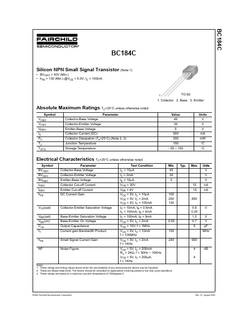
BC184CAbsolute Maximum Ratings T C =25°C unless otherwise notedElectrical Characteristics T C =25°C unless otherwise notedNotes:1.These ratings are limiting values above which the serviceability of any semiconductor device may be impaired.2.These are steady state limits. The factory should be consulted on applications involving pulsed or low duty cycle operations.3.These ratings are based on a maximum junction temperature of 150degrees C.Symbol ParameterValue Units V CBO Collector-Base Voltage 45V V CEO Collector-Emitter Voltage 30V V EBO Emitter-Base Voltage 5V I C Collector Current (DC)500mA P C Collector Dissipation (T a =25°C) (Note 2, 3)350mW T J Junction Temperature 150°C T STGStorage Temperature- 55 ~ 150°CSymbol ParameterTest ConditionMin.Typ.Max.Units BV CBO Collector-Base Voltage I C = 10µA 45V BV CEO Collector-Emitter Voltage I C = 2mA 30V BV EBO Emitter-Base Voltage I E = 10µA 5V I CBO Collector Cut-off Current V CB = 30V 15nA I EBO Emitter Cut-off Current V EB = 4V15nAh FEDC Current GainV CE = 5V, I C = 10µA V CE = 5V, I C = 2mA V CE = 5V, I C = 100mA 100250130800V CE (sat)Collector-Emitter Saturation Voltage I C = 10mA, I B = 0.5mA I C = 100mA, I B = 5mA 0.60.25V V BE (sat)Base-Emitter Saturation Voltage I C = 100mA, I B = 5mA 1.2V V BE (on)Base-Emitter On Voltage V CE = 5V, I C = 2mA 0.550.7V C OB Output CapacitanceV CE = 10V, f = 1MHz 5pF f T Current gain Bandwidth Product V CE = 5V, I C = 10mA f = 100MHz 150MHzh FE Small Signal Current Gain V CE = 5V, I C = 2mA f = 1KHz240900NFNoise FigureV CE = 5V, I C = 200mAR G = 2K Ω, f = 30Hz ~ 15KHz V CE = 5V, I C = 200µA, f = 1KHz44dBBC184CSilicon NPN Small Signal Transistor (Note 1)•BV CEO = 30V (Min.)•h FE = 130 (Min.) @V CE = 5.0V, I C = 100mA1. Collector2. Base3. EmitterTO-921BC184CTRADEMARKSThe following are registered and unregistered trademarks Fairchild Semiconductor owns or is authorized to use and is not intended to be an exhaustive list of all such trademarks.DISCLAIMERFAIRCHILD SEMICONDUCTOR RESERVES THE RIGHT TO MAKE CHANGES WITHOUT FURTHER NOTICE TO ANY PRODUCTS HEREIN TO IMPROVE RELIABILITY, FUNCTION OR DESIGN. FAIRCHILD DOES NOT ASSUME ANY LIABILITY ARISING OUT OF THE APPLICATION OR USE OF ANY PRODUCT OR CIRCUIT DESCRIBED HEREIN;NEITHER DOES IT CONVEY ANY LICENSE UNDER ITS PATENT RIGHTS, NOR THE RIGHTS OF OTHERS.LIFE SUPPORT POLICYFAIRCHILD’S PRODUCTS ARE NOT AUTHORIZED FOR USE AS CRITICAL COMPONENTS IN LIFE SUPPORT DEVICES OR SYSTEMS WITHOUT THE EXPRESS WRITTEN APPROVAL OF FAIRCHILD SEMICONDUCTOR CORPORATION.As used herein:1. Life support devices or systems are devices or systems which, (a) are intended for surgical implant into the body,or (b) support or sustain life, or (c) whose failure to perform when properly used in accordance with instructions for use provided in the labeling, can be reasonably expected to result in significant injury to the user.2. A critical component is any component of a life support device or system whose failure to perform can be reasonably expected to cause the failure of the life support device or system, or to affect its safety or effectiveness.PRODUCT STATUS DEFINITIONS Definition of TermsDatasheet Identification Product Status DefinitionAdvance InformationFormative or In Design This datasheet contains the design specifications for product development. Specifications may change in any manner without notice.PreliminaryFirst ProductionThis datasheet contains preliminary data, andsupplementary data will be published at a later date.Fairchild Semiconductor reserves the right to make changes at any time without notice in order to improve design.No Identification Needed Full ProductionThis datasheet contains final specifications. Fairchild Semiconductor reserves the right to make changes at any time without notice in order to improve design.Obsolete Not In ProductionThis datasheet contains specifications on a product that has been discontinued by Fairchild semiconductor.The datasheet is printed for reference information only.FACT™FACT Quiet series™FAST ®FASTr™FRFET™GlobalOptoisolator™GTO™HiSeC™I 2C™ImpliedDisconnect™ISOPLANAR™LittleFET™MicroFET™MicroPak™MICROWIRE™MSX™MSXPro™OCX™OCXPro™OPTOLOGIC ®OPTOPLANAR™PACMAN™POP™Power247™PowerTrench ®QFET™QS™QT Optoelectronics™Quiet Series™RapidConfigure™RapidConnect™SILENT SWITCHER ®SMART START™SPM™Stealth™SuperSOT™-3SuperSOT™-6SuperSOT™-8SyncFET™TinyLogic™TruTranslation™UHC™UltraFET ®VCX™ACEx™ActiveArray™Bottomless™CoolFET™CROSSVOLT ™DOME™EcoSPARK™E 2CMOS™EnSigna™Across the board. Around the world.™The Power Franchise™Programmable Active Droop™。
IRM-3638中文资料

元器件交易网EVERLIGHT ELECTRONICS CO.,LTD.Technical Data Sheet Infrared Remote-control Receiver ModuleIRM-3638Features‧High protection ability against EMI . ‧Circular lens to improve the receive characteristic. ‧Line-up for various center carrier frequencies. ‧Low voltage and low power consumption. ‧High immunity against ambient light. ‧Photodiode with integrated circuit. ‧TTL and CMOS compatibility. ‧Long reception distance. ‧High sensitivity. ‧Suitable min. burst length≧6 or 10 pulses/burst. ‧Pb free. ‧The product itself will remain within RoHS compliant version.DescriptionsThe device is a miniature type infrared remote control system receiver which has been developed and designed by utilizing the most updated IC technology. The PIN diode and preamplifier are assembled on lead frame, the epoxy package is designed as an IR filter. The demodulated output signal can directly be decoded by a microprocessor.Applications1. Optical switch 2. Light detecting portion of remote control ․AV instruments such as Audio, TV, VCR, CD, MD, etc. ․Home appliances such as Air-conditioner, Fan , etc. ․The other equipments with wireless remote control. ․CATV set top boxes ․Multi-media EquipmentPART Chip Lead Frame PackageEverlight Electronics Co., Ltd. Device No:DMO-036-185MATERIAL Silicon SPCC Epoxyhttp:\\ Prepared date:07-20-2005COLOR --Silver white BlackRev 2 Page: 1 of 9Prepared by:Carryll Hsu元器件交易网EVERLIGHT ELECTRONICS CO.,LTD.IRM-3638Package DimensionsOUT GND VccNotes: 1.All dimensions are in millimeters. 2.Tolerances unless dimensions ±0.3mm.Absolute Maximum Ratings (Ta=25℃)Parameter Supply Voltage Operating Temperature Storage Temperature Soldering Temperature Symbol Vcc Topr Tstg Tsol Rating 6 -25 ~ +85 -40 ~ +85 260 Unit V ℃ ℃ ℃ 4mm from mold body less than 10 seconds NoticeEverlight Electronics Co., Ltd. Device No:DMO-036-185http:\\ Prepared date:07-20-2005Rev 2Page: 2 of 9Prepared by:Carryll Hsu元器件交易网EVERLIGHT ELECTRONICS CO.,LTD.IRM-3638Recommended Operating ConditionSupply Voltage Rating: Vcc 2.7V to 5.5VElectro-Optical Characteristics (Ta=25℃, and Vcc=3.0V)Parameter Consumption Current B.P.F Center Frequency Peak Wavelength Reception Distance Half Angle(Horizontal) Half Angle(Vertical) High Level Pulse Width Low Level Pulse Width High Level Output Voltage Low Level Output Voltage Symbol Icc Fo λp L0 L45 Θh Θv TH TL VH VL MIN. ------14 6 ----400 400 2.7 --TYP. --38 940 ----45 45 ------0.2 MAX. 2 ------------800 800 --0.5 deg deg μs μs V V At the ray axis *2 At the ray axis *1 Unit mA KHz nm m Condition No signal inputNotes: *1:The ray receiving surface at a vertex and relation to the ray axis in the range of θ= 0° and θ=45°. *2:A range from 30cm to the arrival distance. Average value of 50 pulses.Everlight Electronics Co., Ltd. Device No:DMO-036-185http:\\ Prepared date:07-20-2005Rev 2Page: 3 of 9Prepared by:Carryll Hsu元器件交易网EVERLIGHT ELECTRONICS CO.,LTD.IRM-3638Test Method:The specified electro-optical characteristics is satisfied under the following Conditions at the controllable distance. Measurement place A place that is nothing of extreme light reflected in the room. External light Project the light of ordinary white fluorescent lamps which are not high Frequency lamps and must be less then 10 Lux at the module surface. (Ee≦10Lux) Standard transmitter A transmitter whose output is so adjusted as to Vo=400mVp-p and the output Wave form shown in Fig.-1.According to the measurement method shown in Fig.-2 the standard transmitter is specified. However , the infrared photodiode to be used for the transmitter should be λp=940nm,∆λ=50nm. Also, photodiode is used of PD438B(Vr=5V). (Standard light / Light source temperature 2856°K). Measuring system According to the measuring system shown in Fig.-3Block Diagram:VsIN Input CGA & filter DemodulatorOUT µCOscillatorCarrier frequency f0AGC/ATC & digital controlModulated IR signal min 6/10 pulsesGNDEverlight Electronics Co., Ltd. Device No:DMO-036-185http:\\ Prepared date:07-20-2005Rev 2Page: 4 of 9Prepared by:Carryll Hsu元器件交易网EVERLIGHT ELECTRONICS CO.,LTD.IRM-3638Application Circuit:RC Filter should be connected closely between Vcc pin and GND pin.Fig.-1Transmitter Wave FormD.U.T output PulseCarrier frequency is adjusted to center frequency of each product.OUTPUT PULSE OF DEVICEIR TANSMITTER OUTPUT WAVE FORMDuty=0.5Fig.-2Measuring Method20cm 10k +5.0± 0.1VFig.-3Measuring SystemL: Transmission Distance10uFθ θVcc OUT D.U.TVoutStandard TransmitterStandard Transmitter100kVout GNDOscilloscopeθ: Angle Of Horizontal & Vertical DirectionEverlight Electronics Co., Ltd. Device No:DMO-036-185http:\\ Prepared date:07-20-2005Rev 2Page: 5 of 9Prepared by:Carryll Hsu元器件交易网EVERLIGHT ELECTRONICS CO.,LTD.IRM-3638Typical Electro-Optical Characteristics CurvesFig.-4 Relative Spectral Sensitivity vs. Wavelength Fig.-5 Relative Transmission Distance vs. DirectionθFig.-6 Output Pulse Length vs. Arrival DistanceFig.-7 Arrival Distance vs. Supply Voltage17.5 14.0 10.5 7.0 3.5Everlight Electronics Co., Ltd. Device No:DMO-036-185http:\\ Prepared date:07-20-2005Rev 2Page: 6 of 9Prepared by:Carryll Hsu元器件交易网EVERLIGHT ELECTRONICS CO.,LTD.IRM-3638Typical Electro-Optical Characteristics CurvesFig.-8 Relative Transmission Distance vs. Center Carrier Frequency Fig.-9 Arrival Distance vs. Ambient Temperature17.5Transmission Distance Lc (m)14.0 10.5 7.0 3.5Ambient Temperature Ta (°C)Everlight Electronics Co., Ltd. Device No:DMO-036-185http:\\ Prepared date:07-20-2005Rev 2Page: 7 of 9Prepared by:Carryll Hsu元器件交易网EVERLIGHT ELECTRONICS CO.,LTD.IRM-3638Reliability Test Item And ConditionThe reliability of products shall be satisfied with items listed below. Confidence level:90% LTPD:10% Test Items Test Conditions 1 cycle Temperature cycle -25℃ +85℃ n=22,c=0 Failure Judgement Criteria Samples(n) Defective(c)(30min)(5min)(30min) 300 cycle test Temp: +85℃High temperature test Vcc:5V 1000hrs Low temperature storage High temperature High humidity Temp: -40℃ 1000hrs Ta: 85℃,RH:85% 1000hrs Temp: 260±5℃ 10sec 4mm From the bottom of the package.L0≦ L×0.8 L45≦ L×0.8n=22,c=0n=22,c=0 L: Lower specification limit n=22,c=0Solder heatn=22,c=0Everlight Electronics Co., Ltd. Device No:DMO-036-185http:\\ Prepared date:07-20-2005Rev 2Page: 8 of 9Prepared by:Carryll Hsu元器件交易网EVERLIGHT ELECTRONICS CO.,LTD.IRM-3638Packing Quantity Specification1. 1500 PCS/1Box 2. 10 Boxes/1CartonLabel Form SpecificationCPN: Customer’s Production Number P/N : Production Number QTY: Packing Quantity CAT: Ranks HUE: Peak Wavelength REF: Reference LOT No: Lot Number MADE IN TAIWAN: Production PlaceIRM-3638Notes1. Above specification may be changed without notice. EVERLIGHT will reserve authority on material change for above specification. 2. When using this product, please observe the absolute maximum ratings and the instructions for using outlined in these specification sheets. EVERLIGHT assumes no responsibility for any damage resulting from use of the product which does not comply with the absolute maximum ratings and the instructions included in these specification sheets. 3. These specification sheets include materials protected under copyright of EVERLIGHT corporation. Please don’t reproduce or cause anyone to reproduce them without EVERLIGHT’s consent.EVERLIGHT ELECTRONICS CO., LTD. Office: No 25, Lane 76, Sec 3, Chung Yang Rd, Tucheng, Taipei 236, Taiwan, R.O.CTel: 886-2-2267-2000, 2267-9936 Fax: 886-2267-6244, 2267-6189, 2267-6306 http:\\Everlight Electronics Co., Ltd. Device No:DMO-036-185http:\\ Prepared date:07-20-2005Rev 2Page: 9 of 9Prepared by:Carryll Hsu。
CH438DS1
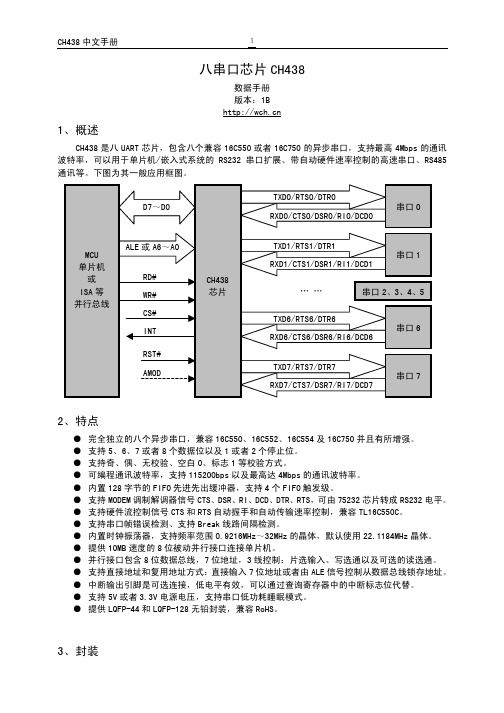
类型 输入
引脚说明
MODEM 信号,清除发送,低电平有效,内置弱上拉 CH438Q 没有该引脚
22.1184MHz
1.8432MHz
115.2Kbps 44.2368MHz 2.7648Mbps
18.432MHz
36.864MHz
2.304Mbps
14.7456MHz
29.4912MHz 1.8432Mbps
11.0592MHz
0.9216MHz
57.6Kbps
22.1184MHz 1.3824Mbps
0
0 TFIFORST RFIFORST FIFOEN
3 X R/W LCR DLAB BREAKEN PARMODE1 PARMODE0 PAREN STOPBIT WORDSZ1 WORDSZ0
4 X R/W MCR 0
0
AFE
LOOP OUT2 OUT1
RTS
DTR
5 X RO LSR RFIFOERR TEMT THRE BREAKINT FRAMEERR PARERR OVERR DATARDY
41-43,45,58, 115-119,121,126,127
47 48
引脚名称 VCC GND
NC.
XI XO
类型 电源 电源
空脚
输入 输出
引脚说明 正电源端 公共接地端
禁止连接
晶体振荡的输入端,需要外接晶体及振荡电容 晶体振荡的反相输出端,需要外接晶体及振荡电容
GJB438B 接口设计说明IDD 模板

[键入文字]文档标识及版本号:XX项目标识.IDD V1.0 密级:秘密★5年编制/修订日期:yyyy-mm-dd文档名称:XX项目中文名称-接口设计说明接口设计说明《XX项目》接口设计说明编制单位:编写:审核:批准:修改记录目录1 范围 (1)1.1标识 (1)1.2系统概述 (1)1.3文档概述 (1)2 引用文档 (2)3 接口设计 (2)3.1接口标识和接口图 (2)3.X(接口的项目唯一的标识符) (3)4 需求的可追踪性 (6)5 注释 (7)1 范围1.1标识【本条应描述本文档所适用的系统、接口实体和接口的完整标识,适用时,包括其标识号、名称、缩略名、版本号和发布号。
】表1-1本文档所适用的系统、接口实体和接口1.2系统概述【本条应概述本文档所适用的系统和软件的用途,还应描述系统与软件的一般特性;概述系统开发、运行和维护的历史;标识项目的需方、用户、开发方和保障机构等;标识当前和计划的运行现场;列出其他有关文档。
】(本章若无内容,则标识为“本章无内容”,并说明理由。
)1.3文档概述【本条应概述本文档的用途和内容,并描述与它的使用有关的保密性方面的要求。
】(本章若无内容,则标识为“本章无内容”,并说明理由。
)2 引用文档【本章应列出引用文档的编号、标题、编写单位、修订版及日期,还应标识不能通过正常采购活动得到的文档的来源。
】(本章若无内容,则标识为“本章无内容”,并说明理由。
)3 接口设计3.1接口标识和接口图【对于1.1中所标识的每个接口,本条应描述赋予该接口的项目唯一的标识符,适当时应使用名称、编号、版本和文档引用等标识接口实体(系统、配置项、用户等)。
该标识应说明哪些实体具有固定的接口特性(要给出这些接口实体的接口需求),哪些实体正被开发或修改(这些实体已有各自的接口需求)。
适当时,可使用一个或多个接口图来描述这些接口。
】(本章若无内容,则标识为“本章无内容”,并说明理由。
)3.X(接口的项目唯一的标识符)【本条(从3.2开始编号)应通过项目唯一的标识符标识接口,应简要标识接口实体,并且应根据需要分条描述接口实体的单方或双方的接口特性。
AOD438中文资料

SymbolTyp Max 14.2203950R θJC 0.8 1.5Maximum Junction-to-AmbientASteady-State °C/W Maximum Junction-to-CaseCSteady-State°C/WThermal Characteristics ParameterUnits Maximum Junction-to-Ambient At ≤ 10s R θJA °C/W AOD438AOD438SymbolMin TypMaxUnits BV DSS 30V 1T J =55°C5I GSS 100nA V GS(th)1 1.83V I D(ON)85A 2.8 3.5T J =125°C4.45.54.4 5.5m Ωg FS 106S V SD 0.721V I S85A C iss 32003840pF C oss 590pF C rss 414pF R g0.540.7ΩQ g (10V)6376nC Q g (4.5V)3340nC Q gs 8.6nC Q gd 17.6nC t D(on)12ns t r 15.5ns t D(off)40ns t f 14ns t rr 3441ns Q rr30nCTHIS PRODUCT HAS BEEN DESIGNED AND QUALIFIED FOR THE CONSUMER MARKET. APPLICATIONS OR USES AS CRITICAL COMPONENTS IN LIFE SUPPORT DEVICES OR SYSTEMS ARE NOT AUTHORIZED. AOS DOES NOT ASSUME ANY LIABILITY ARISING OUT OF SUCH APPLICATIONS OR USES OF ITS PRODUCTS. AOS RESERVES THE RIGHT TO IMPROVE PRODUCT DESIGN,FUNCTIONS AND RELIABILITY WITHOUT NOTICE.Gate Drain Charge V GS =0V, V DS =15V, f=1MHz SWITCHING PARAMETERS Total Gate Charge Gate Source Charge Gate resistanceV GS =0V, V DS =0V, f=1MHzV GS =4.5V, V DS =15V, I D =20ATotal Gate Charge Turn-On Rise Time Turn-Off DelayTime V GS =10V, V DS =15V, R L =0.75Ω, R GEN =3ΩTurn-Off Fall TimeTurn-On DelayTime m ΩV GS =4.5V, I D =20AI S =1A,V GS =0VV DS =5V, I D =20AMaximum Body-Diode Continuous CurrentInput Capacitance Output CapacitanceDYNAMIC PARAMETERS R DS(ON)Static Drain-Source On-ResistanceForward TransconductanceDiode Forward Voltage I DSS µA Gate Threshold Voltage V DS =V GS I D =250µA V DS =24V, V GS =0VV DS =0V, V GS = ±20V Zero Gate Voltage Drain Current Gate-Body leakage current Electrical Characteristics (T J =25°C unless otherwise noted)STATIC PARAMETERS Parameter Conditions Body Diode Reverse Recovery TimeBody Diode Reverse Recovery Charge I F =20A, dI/dt=100A/µsDrain-Source Breakdown Voltage On state drain currentI D =250µA, V GS =0V V GS =10V, V DS =5V V GS =10V, I D =20AReverse Transfer Capacitance I F =20A, dI/dt=100A/µsA: The value of R θJA is measured with the device mounted on 1in 2 FR-4 board with 2oz. Copper, in a still air environment with T A =25°C. The Power dissipation P DSM is based on steady-state R θJA and the maximum allowed junction temperature of 150°C. The value in any givenapplication depends on the user's specific board design, and the maximum temperature of 175°C may be used if the PCB or heatsink allows it.B. The power dissipation P D is based on T J(MAX)=175°C, using junction-to-case thermal resistance, and is more useful in setting the upperdissipation limit for cases where additional heatsinking is used. It is used to determine the current rating, when this rating falls below the package limit.C: Repetitive rating, pulse width limited by junction temperature T J(MAX)=175°C.D. The R θJA is the sum of the thermal impedence from junction to case R θJC and case to ambient.E. The static characteristics in Figures 1 to 6 are obtained using <300 µs pulses, duty cycle 0.5% max.F. These tests are performed with the device mounted on 1 in 2 FR-4 board with 2oz. Copper, in a still air environment with T A =25°C. The SOA curve provides a single pulse rating.G. The maximum current rating is limited by the package current capability. Rev 2: July 2005AOD438AOD438AOD438。
PD438B中文资料
Storage Temperature Tstg Notes: *1:Soldering time≦5 seconds.
Everlight Electronics Co., Ltd. Device No:DPD-043-001
http:\\ Prepared date:06-15-2004
10
2
1
80 60
f=1MHZ VR=3V
VR=10V O Ta=25 C
10
0
t
40
10
-1
20
10 10
-2
-3
0 0.1 1 10 100
10
1
10
2
10
3
10
4
10
5
Everlight Electronics Co., Ltd. Device No:DPD-043-001
http:\\ Prepared date:06-15-2004
Applications
․High speed photo detector ․Camera ․Optoelectronic switch ․VCRs , Video camera
Device Selection Guide
LED Part No. PD Chip Material Silicon Lens Color Black
Package Dimensions
Color Mark
Sensitive Surface
Hale Waihona Puke 4.8±0.20.5± 0.1
1.5Max
1 2
2.54
1.0Min
14.5Min
6.60±0.3
3.8±0.2
438II客户手册

Motor Analyzer
用户手册
March 2016 (Simplified Chinese)
©2016 Fluke Corporation. All rights reserved. All product names are trademarks of their respective companies.
有限担保和有限责任
Fluke 担保在正常使用和保养的情况下,其产品没有材料和工艺上的缺陷。从寄送之日起,担保期为三年。部件、产品修理 和服务的担保期限为 90 天。本担保仅限于 Fluke 授权零售商的原购买人或最终用户,并且不适用于一次性电池、电缆接 头、电缆绝缘转换接头或 Fluke 认为由于误用、改装、疏忽、污染及意外或异常操作或处理引起的任何产品损坏。 Fluke 担 保软件能依照功能规格正常运行 90 天,并且软件是记录在无缺陷的媒介上。 Fluke 并不担保软件毫无错误或在运行中不会 中断。 Fluke 授权的零售商应仅对最终用户就新的和未使用的产品提供本担保,但无权代表 Fluke 公司提供额外或不同的担保。只 有通过 Fluke 授权的销售店购买的产品或者买方已经按适用的国际价格付款才能享受 Fluke 的担保支持。在一国购买的产品 需在他国修理时, Fluke 有权向买方要求负担重大修理 / 零件更换费用。 Fluke 的担保为有限责任,由 Fluke 决定是否退还购买金额、免费修理或更换在担保期间退还 Fluke 授权服务中心的故障产 品。 如需要保修服务,请与您就近的 Fluke 授权服务中心联系,获得退还授权信息;然后将产品寄至服务中心,并附上产品问题 描述,同时预付运费和保险费 (目的地离岸价格) 。 Fluke 不承担运送途中发生的损坏。在保修之后,产品将被寄回给买方 并提前支付运输费 (目的地交货) 。如果 Fluke 认定产品故障是由于疏忽、误用、污染、修改、意外或不当操作或处理状况 而产生,包括未在产品规定的额定值下使用引起的过压故障;或是由于机件日常使用损耗,则 Fluke 会估算修理费用,在获 得买方同意后再进行修理。在修理之后,产品将被寄回给买方并预付运输费;买方将收到修理和返程运输费用 (寄发地交 货)的帐单。 本担保为买方唯一能获得的全部补偿内容,并且取代所有其它明示或隐含的担保,包括但不限于适销性或满足特殊目的任何 隐含担保。 FLUKE 对任何特殊、间接、偶发或后续的损坏或损失概不负责,包括由于任何原5
[06]可靠性和可维护性大纲-438C
![[06]可靠性和可维护性大纲-438C](https://img.taocdn.com/s3/m/7b6ab99e09a1284ac850ad02de80d4d8d05a0147.png)
文件更改记录表目录1 范围 (1)1.1标识 (1)1.2系统概述 (1)1.3文档概述 (1)2 引用文档 (1)3 软件生存周期 (1)3.1软件生存周期各阶段对可靠性和可维护性要求 (1)3.2软件生存周期可靠性和可维护性度量方法 (2)4 软件可靠性和可维护性大纲要求 (2)4.1考虑的主要因素: (2)4.2主要活动项目 (2)4.3可行性论证 (2)4.3.1在需求分析阶段 (3)4.3.2运行环境分析 (3)4.3.3选定或制定规范和准则 (4)4.3.4软件可靠性和可维护性分析 (4)4.3.5评审 (4)4.3.6可靠性、可维护性文件和数据记录 (5)4.3.7培训 (5)4.3.8维护保障要求 (6)1 范围1.1 标识a)文档标识号:TN/x-DO-DS-V{N.xx};b)标题:;c)软件名称;d)软件缩写:e)软件版本号。
1.2 系统概述1.3 文档概述2 引用文档表-X 引用文件3 软件生存周期3.1 软件生存周期各阶段对可靠性和可维护性要求◆可行性研究与计划阶段——进行项目可行性分析。
制订初步项目开发计划,提出软件可靠性和可维护性目标、要求及经费。
◆需求分析阶段——将合同的技术内容细化为具体产品需求。
分析和确定软件可靠性和维护性的目标,制定大纲。
◆概要设计阶段——进行软件可靠性和可维护性目标分配,进行可靠性和可维护性概要设计,并明确对详细设计的具体要求。
◆详细设计阶段——进行软件可靠性和可维护性详细设计,编写相应的设计说明,明确对实阶段的具体要求。
◆实现阶段——进行单元测试,分析和验证有关软件可靠性和可维护性的部分要求。
◆组装测试阶段——进行组装测试,并进一步分析软件可靠性和可维护性。
◆确认测试阶段——确认软件产品的可靠性和可维护性是否达到预定的目标。
使用和维护阶段——采集数据,定期评价,加强维护管理,以确保软件的可靠性和可维护性增长。
3.2 软件生存周期可靠性和可维护性度量方法在软件生存周期的各个阶段,应进行与可靠性和可维护性有关的度量,度量方法通常分定性的估计、定量的预测和测量等等。
日本FUJI信号隔离器PWB系列

消耗功率、消耗电流 使用温度、湿度范围 零点调整范围 量程调整范围 外形尺寸 重量
2
PDF 文件使用 "pdfFactory Pro" 试用版本创建
PWB 系列信号变换器
直流变换器 PWBDC
富士電機
直流变换器将直流电压、电流的输入信号变换为用户所需的直流电压、电流的输出信号。变换的同时,实现输入和输 出的隔离。 技术规格
精度 温度特性 响应时间 隔离电阻 ±0.1% ±0.015% / ℃ 0.5ms 以内(0~90%) 大于 100MΩ 100VAC 功耗 200VAC 24VDC 110VDC 输入信号 (输入电 阻) 第一输出 信号(负载 电阻) 调整 直流电流 零点/量程 调整范围 直流电流 直流电压 直流电压 3.5VA 4.5VA 100mA 40mA 代号 8 A B C H P 代号 10 0 3 4 辅助电源 AC85~264V,50/60Hz DC24V±10% DC110V±10% 代号 6、 7 13 14 15 16 22 第一输出信号 DC1~5V DC0~5V DC0~10V DC4~20mA DC0~20mA 输入信号 DC0~5V DC0~10V DC1~5V DC4~20mA DC0~20mA
测量方式 精度 温度特性 响应时间 隔离电阻 有效值(RMS) ±0.4% ±0.02% / ℃ 0.5s 以内(0~90%) 大于 100MΩ 100VAC 功耗 200VAC 24VDC 110VDC 交流电压 输入信号 交流电流 第一输出 信号(负载 电阻) 直流电流 直流电压 第二输出 信号(负载 电阻) 通信输出 RS485 使用简易 设定器(PWBAJ),只能调整第 调整 零点/量程 调整范围 一输出 使用智能设定器(PWBPD),第一、第二 输出都能 调整。 直流电流 4~20MA(350Ω以下) 直流电压 0~1A、 0~5A 0~5V(1kΩ以上)、0~10V(2kΩ以上)、 1~5V(1kΩ以上) 0~20MA(750Ω以下)、 4~20MA(750Ω以下) 1~5V(1kΩ以上) 代号 10 0 3 4 代号 9 A H V Y 辅助电源 AC85~264V,50/60Hz DC24V±10% DC110V±10% 5VA 7.5VA 120mA 50mA 代号 8 A B C H P 第二输出信号 DC1~5V DC4~20mA RS485 通信输出 无 代号 6、 7 01 05 11 15 第一输出信号 DC1~5V DC0~5V DC0~10V DC4~20mA DC0~20mA 输入信号 AC0~1A AC0~5A AC0~110V AC0~150V
光敏二极管规格书PD438

5
30
nA
VR=10.0V Ee=0mW/cm2
反向击穿电压
BVR
35
--
--
V
IR=100uA Ee=0mW/cm2
总计电容
Ct
--
44
--
pF
VR=3.0V Ee=0mW/cm2f=1MHz
上升/下降时间
tr/tf
--
50/50
ห้องสมุดไป่ตู้nS
VR=10.0V RL=50Ω
典型光电特性图:
产品包装:
防静电包装袋, 1000只/袋.
极限参数值:
参 数
符 号
最 大 值
单 位
反 向 电 压
VR
35
V
耗 散 功 率
Pd
150
mW
焊 接 温 度
Tsol
260
℃
工 作 温 度
Topr
-20~+85
℃
存 储 温 度
Tstg
-40~+85
℃
注:*1. 焊接时间≤ 5 秒
光电特性: (Ta=25℃)
项 目
符号
最小值
典型值
最大值
单位
条件
光谱带宽
光敏二极管
型号:PD438
器件简介
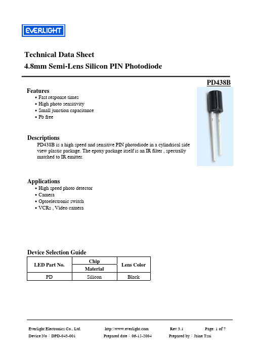
PD438是一款高速、高灵敏的插脚式光敏二极管,采用半圆柱外形平面感光结构,用透明环氧材料封装,对可见光和红外光均有很高的感光灵敏度。
器件特性
快速响应
高感光灵敏度
环保无铅,符合RoHS标准
应用:
高速光传感器;
照相机;
光电开关
录像机,视频录像机等。
外形尺寸图
型八总线收发器(三态
20
20 μA
IOZL
低关态输出电流 Vcc= 最 大 接 2.0V VIL=最大 Vo=0.4V
-400
-400 μA
IOS 输出短路电流 Vcc=最大 Vo=0V
-40
-225 -40
-225 mA
ICCH
高电平电源电流 Vcc=最大
ICCL 低电平电源电流 输出开路
ICCZ 禁态电源电流
输出为高 输出为低 输出禁态
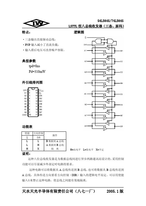
特点:
54LS645/74LS645 LSTTL 型八总线收发器(三态、原码)
逻辑图
·三态输出直接驱动总线; ·PNP 输入减小了直流负载; ·输入滞后电压可改善噪声容限。
典型参数 tpd=8ns Pd=310mW
外引线排列图
功能表
使能 方向控制
操作
L
L
L
H
H
X
说明:
B 数据到 A 总线 A 数据到 B 总线
天水天光半导体有限责任公司(八七一厂) 2005.1 版
54LS645/74LS645
LSTTL 型八总线收发器(三态、原码)
推荐工作条件
符号
参数名称
Vcc
电源电压
VIH
输入高电平电压
VIL
输入低电平电压
IOH
输出高电平电流
IOL
输出低电平电流
TA
工作环境温度
最小 4.75 2.0
-40
74Ⅱ 参数值 典型 最大
70
48 70 mA
90
62 90 mA
95
64 95 mA
注:所有典型值均在 Vcc=5.0V, TA=25℃下测量得出。
天水天光半导体有限责任公司(八七一厂) 2005.1 版
PJ78L05CS资料
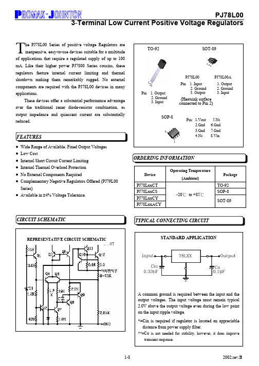
he PJ78L00 Series of positive voltage Regulators are inexpensive, easy-to-use devices suitable for a multitudeof applications that require a regulated supply of up to 100 mA. Like their higher power PJ7800 Series cousins, these regulators feature internal current limiting and thermal shutdown making them remarkably rugged. No external components are required with the PJ78L00 devices in many applications.These devices offer a substantial performance advantage over the traditional zener diode-resistor combination, as output impedance and quiescent current are substantially reduced. z Wide Range of Available, Fixed Output Voltages z Low Costz Internal Short Circuit Current Limiting z Internal Thermal Overload Protection z No External Components RequiredzComplementary Negative Regulators Offered (PJ79L00 Series)zAvailable in ±4% Voltage Tolerance.TDeviceOperating Temperature(Ambient)PackagePJ78LxxCT TO-92 PJ78LxxCS SOP-8PJ78LxxCYPJ78LxxACY-20℃ to +85℃SOT-89REPRESENTATIVE CIRCUIT SCHEMATICRATING SYMBOL PJ78L00 SERIESUNITInput Voltage Vi *1 35 V Input VoltageVi *2 40 V Storage Temperature Range Tstg -25 to +150 ℃ Operating Ambient Temperature Topr -20 to +85 ℃ Operating Junction Temperature Tj 0 to +125 ℃ Temperature CoefficientTc0.005%/℃Note :*1. PJ78L05 to PJ78L18 *2. PJ78L24z This specification applies only for DC power dissipation permitted by absolute maximum ratings.zPulse testing techniques are used to maintain the junction temperature as close to the ambient temperature as possible. Thermal effects must be taken into account separately. All characteristics are measured with a 0.33uF capacitor across the input and a 0.1uF capacitor across the output.(Vi=10V, Io=40mA, Ci=0.33µF, Co=0.1µF, 0℃ <Tj<+125℃ unless otherwise noted.)CHARACTERISTIC SYMBOLMIN TYP MAX UNITOutput Voltage (Tj=+25℃) Vo 4.8 5.0 5.2 VdcLine Regulation (Tj=+25℃, Io=40mA) 7.0V ≤Vi ≤20V 8.0V ≤Vi ≤20V REGline 32 26 150 100 mV Load Regulation Tj=+25℃, 1.0mA ≤Io ≤100mA Tj=+25℃, 1.0mA ≤Io ≤40mA REGload 15 8 60 30 mV Output Voltage 7.0V ≤Vi ≤20V, 1.0mA ≤Io ≤40mA Vi = 10V, 1.0mA ≤Io ≤70mA Vo 4.8 4.8 5.2 5.2 Vdc Input Bias Current (Tj=+25℃) (Tj=+125℃) I IB 3.8 6.0 5.5mA Input Bias Current Change 8.0V ≤Vi ≤20V 1.0mA ≤Io ≤40mA∆ I IB1.5 0.1 mA Output Noise Voltage (Ta=+25℃, 10Hz ≤f ≤100KHz) Vn 40 µV Ripple Rejection (lo=40mA, f=120Hz, 8.0V ≤Vi ≤18V, Tj=+25℃) RR 40 49 dB Dropout Voltage Vi-Vo 1.7 Vdc(Vi=14V, Io=40mA, Ci=0.33µF, Co=0.1µF,0℃ <Tj<+125℃ , unless otherwise noted.)CHARACTERISTIC SYMBOL MIN TYP MAX UNITOutput Voltage (Tj=+25℃) Vo 7.68 8.0 8.32 Vdc Line Regulation(Tj=+25℃, lo=40mA)10.5V ≤Vi ≤23V , 11V ≤Vi ≤23V,REGline42 36 175 125 mV Load RegulationTj=+25℃, 1.0mA ≤Io ≤100mA Tj=+25℃,1.0mA ≤Io ≤40mA REGload18 10 80 40 mV Output Voltage10.5V ≤Vi ≤23V, 1.0mA ≤Io ≤40mA Vi=14V, 1.0mA ≤Io ≤70mA Vo7.68 7.688.32 8.32VdcInput Bias Current (Tj=+25℃) (Tj=+125℃)I IB3.06.0 5.5 mA Input Bias Current Change 11V ≤Vi ≤23V 1.0mA ≤Io ≤40mA ∆I IB1.5 0.2 mA Output Noise Voltage (Ta=+25℃, 10Hz ≤f ≤100KHz) Vn 54 µVRipple Rejection(lo=40mA, f=120Hz, 12V ≤Vi ≤23V, Tj=+25℃RR36 45dBDropout Voltage (Tj=+25℃) Vi-Vo 1.7 Vdc(VI=16V,IO=40mA,CI=0.33μF, Co=0.1Μf,-40℃<TJ<+125℃(for PJ78Lxx),0℃<tj<125℃(PJ78Lxx)),unless otherwise noted.)CHARACTERISTIC SYMBOLMIN TYP MAX UNITOutput Voltage (Tj=+25℃) Vo 8.64 9.0 9.36 VdcLine Regulation(Tj=+25℃, lo=40mA) 11.5V ≤Vi ≤24V , 12V ≤Vi ≤24V, REGline45 40 175 125 mV Load RegulationTj=+25℃, 1.0mA ≤Io ≤100mA Tj=+25℃,1.0mA ≤Io ≤40mA REGload19 1190 40 mVOutput Voltage11.5V ≤Vi ≤24V, 1.0mA ≤Io ≤40mA Vi=16V, 1.0mA ≤Io ≤70mA Vo 8.64 8.649.36 9.36 Vdc Input Bias Current (Tj=+25℃) (Tj=+125℃)I IB3.0 6.0 5.5 mA Input Bias Current Change 11V ≤Vi ≤23V 1.0mA ≤Io ≤40mA ∆I IB1.5 0.1mA Output Noise Voltage (Ta=+25℃, 10Hz ≤f ≤100KHz) Vn 58µVRipple Rejection(lo=40mA, f=120Hz, 12V ≤Vi ≤23V, Tj=+25℃ RR3745dB Dropout Voltage (Tj=+25℃) Vi-Vo 1.7 Vdc(Vi=19V, Io=40mA, Ci=0.33µF, Co=0.1µF, 0℃ <Tj<+125°C unless otherwise noted.)CHARACTERISTIC SYMBOLMIN TYP MAX UNITOutput Voltage (Tj=+25℃) Vo 11.52 12 12.48 VdcLine Regulation(Tj=+25℃, Io=40mA) 14.5V ≤Vi ≤27V 16V ≤Vj ≤27V REGline55 49250 200 mVLoad RegulationTj=+25℃,1.0mA ≤Io ≤100mA Tj=+25℃, 1.0mA ≤Io ≤40mA REGload22 13100 50 mV Output Voltage14.5V ≤Vi ≤27V,1.0mA ≤Io ≤40Ma Vi=19V, 1.0mA ≤Io ≤70mA Vo 11.52 11.5212.48 12.48 Vdc Input Bias Current (Tj=+25℃) (Tj=+125℃)I IB426.5 6.0 mA Input Bias Current Change 16V ≤Vi ≤27V 1.0mA ≤Io ≤40mA ∆I IB1.5 0.2mA Output Noise Voltage (Ta=+25℃, 10Hz ≤f ≤100KHz) Vn 70µVRipple Rejection(Io=40mA, f=120Hz, 15V ≤Vi ≤25V, Tj=+25℃)RR 3642dBDropout Voltage(Tj=+25℃) Vi-Vo 1.7 Vdc(Vi=23V, Io=40mA, Ci=0.33µF, Co=0.1µF, 0℃ <Tj<+125°C unless otherwise noted.)CHARACTERISTIC SYMBOLMIN TYP MAX UNITOutput Voltage (Tj=+25℃) Vo 14.4 15 15.6 VdcLine Regulation(Tj=+25℃, Io=40mA) 17.5V ≤Vi ≤30V 20V ≤Vi ≤30V REGline 65 58 300 250 mV Load Regulation Tj=+25°C, 1.0mA ≤Io ≤100mA Tj=+25°C, 1.0mA ≤Io ≤40mA REGload 25 12 150 75 mV Output Voltage 17.5V<Vi<30V, 1.0mA ≤Io ≤40mA Vi=23V, 1.0mA ≤Io ≤70mA Vo 14.40 14.40 15.60 15.60Vdc Input Bias Current (Tj=+25℃) (Tj=+125℃)I IB4.4 6.5 6.0 mA Input Bias Current Change 20V ≤Vi ≤30V 1.0mA ≤Io ≤40mA ∆I IB 1.5 0.2 mA Output Noise Voltage (Ta=+25°C, 10Hz ≤f ≤100KHz) Vn 82 µV Ripple Rejection (Io=40mA, f=120Hz,18.5V ≤Vi ≤28.5V,Tj=+25°C) RR 33 39 dBDropoutVoltage (Tj=+25°C) Vi-Vo 1.7 Vdc(Vi=27V, Io=40mA, Ci=0.33µF, Co=0.1µF, 0°C <Tj<+125°C unless otherwise noted.)CHARACTERISTIC SYMBOL MIN TYP MAX UNITOutput Voltage (Tj=+25°C ) Vo 17.28 18 18.72 VdcLine Regulation(Tj=+25°C , Io=40mA)2154V ≤Vi ≤33V 22V ≤Vj ≤33V REGline70 64 325 275 mVLoad RegulationTj=+25°C , 1.0mA ≤Io ≤100mA Tj=+25°C , 1.0mA ≤Io ≤40mA REGload30 15 170 85 mV Output Voltage21.5V ≤Vi ≤33V, 1.0mA ≤Io ≤40mA Vi=27V, 1.0mA ≤Io ≤70mA Vo17.44 17.4418.56 18.56 Vdc Input Bias Current (Tj=+25°C ) (Tj=+125°C )I IB3.16.5 6.0 mA Input Bias Current Change 22V ≤Vi ≤33V 1.0mA ≤Io ≤40mA ∆I IB1.5 0.2 mAOutput Noise Voltage (Ta=+25°C , 10Hz ≤f ≤100KHz) Vn 150 µVRipple Rejection(Io=40mA, f=120Hz, 23V ≤Vi ≤33V, Tj=+25°C ) RR3246dBDropout Voltage (Tj=+25°C ) Vi-Vo 1.7 Vdc(Vi=33V, Io=40mA, Ci=0.33µF, Co=0.1µF, 0°C <Tj<+125°C unless otherwise noted.)CHARACTERISTIC SYMBOLMIN TYP MAX UNITOutput Voltage (Tj=+25°C) Vo 23.04 24 24.96 Vdc Line Regulation(Tj=+25°C, Io=40mA) 27.5V ≤Vi ≤38V 28V ≤Vi ≤38V REGline 35 30 350 300 mV Load Regulation Tj=+25°C, 1.0mA ≤Io ≤100mA Tj=+25°C, 1.0mA ≤Io ≤40mA REGload 40 20200100 mV Output Voltage 28V ≤Vi ≤38V, 1.0mA ≤Io ≤40mA 28V ≤Vi ≤33V, 1.0mA ≤Io ≤70mA Vo 23.32 23.32 24.68 24.68 Vdc Input Bias Current (Tj=+25°C) (Tj=+125°C) I IB 3.1 6.5 6.0 mA Input Bias Current Change 28V ≤Vi ≤38V 1.0mA ≤Io ≤40mA ∆I IB 1.5 0.2 mA Output Noise Voltage (Ta=+25°C, 10Hz ≤f ≤100KHz) Vn 200µVRipple Rejection (Io=40mA, f=120Hz, 29V ≤Vi ≤35V, Tj=+25°C) RR 30 43dBDropout Voltage (Tj=+25°C) Vi-Vo 1.7 VdcFIGURE 1 - DROPOUT VOLTAGE versusJUNCTION TEMPERATUREFIGURE 2 – DROPOUT CHANRACTERISTICSFIGURE 3 - INPUT BIAS CURRENT versusAMBIENT TEMPERATURFIGURE 4 - INPUT BIAS CURRENT versus INPUT VOLTAGE ANRACTERISTICSFIGURE 5 - MAXIMUM AVERAGE POWER DISSIPATION versus AMBIENT TEMPERATURE。
PD43和PD43c介绍
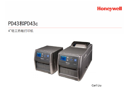
1 in 300 m (984 ft)
1 in 450 m (1475 ft)
性能
用户界面
PD42
graphic LCD display, 160 x 160 pixels 4 LED indicators 1,000-4,000
PD43
LCD: 2.3" Color Display Icon:Icons with Print Button 1,000-4,000
PD43和PD43c概述
功能 打印技术 用户界面
PD43 DT/TT LCD和图标
PD43c DT/TT LCD和图标
打印分辨率
打印速度
203 dpi: 8 dots/mm 300 dpi: 11.8 dots/mm
203 dpi: 50 to 200 mm/sec (2 to 8 ips) 300 dpi: 50 to 150 mm/sec (2 to 6 ips)
19 to 114mm 17.8 to 991mm 0.076 to 0.25mm 8.38 in 2 to 4 mm
25 to 114mm (1 to 4.5 in) NA 2.5 to 7mil 8.38 in NA 82 mm (3.2 in)
19 to 114 mm (0.75 to 4.5 in) 6.4 mm to 4.8 m (0.25 in to 15.7 ft) 0.061 to 0.26mm 8.38 in 1.2 to 26 mm 80 mm (3.15 in) 1 in 450 m (1475 ft)
Ethernet Wireless LAN 802.11
?选择向导wizards使用向导列表来帮助您配置打印或通讯设置或校准介质传modelconnectivitycablescuttercuttertrayltsdispenserribbonadapterplatenrollerlinerlessplatenrollerpd43usbserial213033001usbparallel203182110usbausbb321576004213036001203188100213040001213034001225781001910400024880203185500pd43cmodelprintheadcleaningcardpoweradapterflattopwindowairlineboardingpassshelfairlineboardingpasstrayextendedmediaholderethernetextensioncablepd43203dpi201031420300dpi201031430111050100213038001203943002213037001213039001pd43c203186200213035001modelethernetwifibtuhfrfidhfrfidpd43factoryinstalledonlypd43cpd43和pd43c附件pd43和pd43c附件机器附件platenrollerlinerlessplatenroller无底纸滚筒ribbonadapter色带适配器labeldispenser剥离器labeltakensensormodulelts标签拾取传感器pd43pd43c机器附件cuttermodulecuttertray切刀托盘flattopwindow平顶窗airlineboardingpassshelf航空公司登机牌支架airlineboardingpasstray航空公司登机牌托盘pd43pd43c机器附件extendedmediaholder介质扩展支架ethernetextensioncable以太网延伸电缆usbserialadapterusb串行适配器usbparalleladapterusb并联适配器poweradapter电源适配器pd43pd43c性能pd42pd43zt200pm4ipm43内存标准内存mbflash16mbram128mbflash128mbram1
独家:GJB438标准C版与B版的对比分析

独家:GJB438标准C版与B版的对比分析一. 概述GJB 438 标准名称为《军用软件开发文档通用要求》[1-2]。
其规定了军用软件开发文档编制的种类、结构、格式和内容等要求。
适用于军用软件开发过程中文档的编制。
软件文档是整个软件开发工作的重要产品,是实行管理、监督、控制软件开发的重要方式。
软件文档把软件开发过程中的一些不可的事物转化为可见的文字资料,便于管理人员在各个阶段检查开发计划的进展情况,以提高软件生产过程的可见性和可控性。
软件文档作为软件产品的一部分,文档的质量在很大程度上决定了软件的质量。
随着装备信息化迅速发展,装备中计算机软件的种类、规模以及安全、保密等属性的要求都迅速增加或提高。
2009年5月25日GJB 438B版标准发布,并于2009年8月1日正式实施,其从软件开发管理的角度,规定了相应的文档编制要求,增加了文档的用途和简要说明,增加了软件研制任务书、软件质量保证计划、软件质量保证报告、软件配置管理计划、软件配置管理报告、软件研制总结报告等。
但在实践运用中发现,系统/子系统设计说明对硬件—软件系统的适用场景、软件研制总结报告对质量控制情况等不够明确,软件配置管理计划、软件质量保证计划等独立形成文档的必要性不够充分等问题,因此,2021年12月30日 GJB 438C 版标准修订发布,并于2022年3月1日正式实施,其保留了GJB 438B 版标准的有效方面,改进不足之处,以适应当前我军装备软件研制的需要。
二. 文档章节对比GJB 438C版标准较GJB 438B版标准增加了2个章节,分别是“总则”“页号/页标记”。
取消了9个章节,分别是“文档编制”“软件研制任务书”“软件配置管理计划”“软件质量保证计划”“软件输入/输出手册”“软件中心操作手册”“计算机操作手册”“软件配置管理报告”“软件质量保证报告”。
将GJB 438B版中“文档编制”“文档结构”合并修订为“文档组成”。
- 1、下载文档前请自行甄别文档内容的完整性,平台不提供额外的编辑、内容补充、找答案等附加服务。
- 2、"仅部分预览"的文档,不可在线预览部分如存在完整性等问题,可反馈申请退款(可完整预览的文档不适用该条件!)。
- 3、如文档侵犯您的权益,请联系客服反馈,我们会尽快为您处理(人工客服工作时间:9:00-18:30)。
EVERLIGHT ELECTRONICS CO., LTD. Office: No 25, Lane 76, Sec 3, Chung Yang Rd, Tucheng, Taipei 236, Taiwan, R.O.C
Tel: 886-2-2267-2000, 2267-9936 Fax: 886-2267-6244, 2267-6189, 2267-6306 http:\\
80 60 40
f=1MHZ VR=3V
10
2
1
VR=10V O Ta=25 C
10 10 10 10
0
t
-1
20
-2
0
-3
0.1
1
10
100
10
1
10
2
10
3
10
4
10
5
Everlight Electronics Co., Ltd. Device No:DPD-043-003
http:\\ Prepared date:07-20-2005
Applications
․High speed photo detector ․Camera ․Optoelectronic switch ․VCRs , Video camera
Device Selection Guide
LED Part No. PD Chip Material Silicon Lens Color Black
10
VR=10V 1 20 40 60 80 100
VR=5V 0.5 1 1.5
2
0
3
Everlight Electronics Co., Ltd. Device No:DPD-043-003
http:\\ Prepared date:07-20-2005
Rev 3
O
50 0
0.2 0
-25
0
25
50
75 85 100
600 700 800 900 1000 1100 1200
Fig.3 Dark Current vs. Ambient Temperature
1000
Fig. 4 Reverse Light Current vs. Ee
40 30
100
20
10
Storage Temperature Tstg Notes: *1:Soldering time≦5 seconds.
Everlight Electronics Co., Ltd. Device No:DPD-043-003
http:\\ Prepared date:07-20-2005
元器件交易网
Technical Data Sheet 4.8mm Semi-Lens Silicon PIN Photodiode
PD438B/C1
Features
․Fast response times ․High photo sensitivity ․Small junction capacitance ․Pb free ․The product itself will remain within RoHS compliant version.
pF nS
Everlight Electronics Co., Ltd. Device No:DPD-043-003
http:\\ Prepared date:07-20-2005
Rev 3
Page: 3 of 7
Prepared by:Jaine Tsai
元器件交易网
PD438B/C1
Typical Electro-Optical Characteristics Curves
Fig.1 Power Dissipation vs. Ambient Temperature
200 150 100
0.4
Fig.2 Spectral Sensitivity
1.0 Ta=25 C 0.8 0.6
Red by:Jaine Tsai
元器件交易网
PD438B/C1
Reliability Test Item And Condition The reliability of products shall be satisfied with items listed below. Confidence level:90% LTPD:10% NO. Item Test Conditions Test Hours/ Cycles 10secs 300Cycles Sample Sizes 22pcs 22pcs IL≦L×0.8 L:Lower 300Cycles 22pcs Specification Limit 0/1 Failure Judgement Criteria Ac/R e 0/1 0/1
Page: 4 of 7
Prepared by:Jaine Tsai
元器件交易网
PD438B/C1
Typical Electro-Optical Characteristics Curves
Fig.5 Terminal Capacitance vs. Reverse Voltage Fig.6 Response Time vs. Load Resistance
CPN: Customer’s Production Number P/N : Production Number QTY: Packing Quantity CAT: Ranks HUE: Peak Wavelength REF: Reference LOT No: Lot Number MADE IN TAIWAN: Production Place
PD438B/C1
Package Dimensions
Notes: 1.All dimensions are in millimeters 2.Tolerances unless dimensions ±0.25mm
Absolute Maximum Ratings (Ta=25℃)
Parameter Reverse Voltage Power Dissipation Lead Soldering Temperature Operating Temperature Symbol VR Pd Tsol Topr Rating 32 150 260 -25 ~ +85 -40 ~ +85 Units V mW ℃ ℃ ℃
Everlight Electronics Co., Ltd. Device No:DPD-043-003
http:\\ Prepared date:07-20-2005
Rev 3
Page: 1 of 7
Prepared by:Jaine Tsai
元器件交易网
1 2
Solder heat
TEMP.:260℃±5℃ 15mins 5mins 15mins 5mins 10secs 5mins
Temperature Cycle H : +100℃ L : -40℃
3
Thermal Shock
H :+100℃ L :-10℃
4 5 6 7
High Temperature TEMP.:+100℃ Storage Low Temperature TEMP.:-40℃ Storage DC Operating Life VR=5V 85℃ / 85% R.H High Temperature/ High Humidity
Descriptions
PD438B/C1 is a high speed and sensitive PIN photodiode in a cylindrical side view plastic package. The epoxy package itself is an IR filter , spectrally matched to IR emitter.
1000hrs 1000hrs 1000hrs 1000hrs
22pcs 22pcs 22pcs 22pcs
0/1 0/1 0/1 0/1
Everlight Electronics Co., Ltd. Device No:DPD-043-003
http:\\ Prepared date:07-20-2005
Rev 3
Page: 6 of 7
Prepared by:Jaine Tsai
元器件交易网
PD438B/C1
Packing Quantity Specification
1.500PCS/1Bag,6Bags/1Box 2.10Boxes/1Carton
Label Form Specification
Rev 3
Page: 2 of 7
Prepared by:Jaine Tsai
元器件交易网
PD438B/C1
Electro-Optical Characteristics (Ta=25℃)
Parameter Rang of Spectral Bandwidth Wavelength of Peak Sensitivity Open-Circuit Voltage Short- Circuit Current Reverse Light Current Dark Current Reverse Breakdown Total Capacitance Rise/Fall Time Symbol λ0.5 λp VOC ISC IL Id BVR Ct tr/tf Condition --------Ee=5m W/cm2 λp=940nm Ee=1m W/cm2 λp=940nm Ee=1m W/cm2 λp=940nm VR=5V Ee=0m W/cm2 VR=10V Ee=0m W/cm2 IR=100μA Ee=0m W/cm2 VR=3V f=1MHZ VR=10V RL=1KΩ Min. 760 ------10.2 --32 ----Typ. --940 0.35 18 18 5 170 25 50/50 Max. 1100 ------μA --30 ------nA V Units nm nm V
