FRG1400-16中文资料
中外阀门常用材料对照表

870-890 870-890
870-890
950-970
630
870-890
950-970
630
950-970
630
950-970
630
950-970
720
950-970
720
950-970
720
960-980
650
0.05
1050-1100 快冷
2~3
1010-1150 快冷
0.5
1040-1150 快冷
中、美、日阀门常用材料对照表
名称
可焊高 温用
碳素钢 铸钢
高温高压 用合金钢
铸钢 马氏体耐 热不锈钢 合金钢
铸钢
高温用奥 氏体不锈 钢铸钢
低温压 力部件 用奥氏 体铸钢
低温压 力部件 用铁素 体铸钢 低温用 碳素钢 低合金 钢锻钢
低温压 力部件, 用奥氏 体锻钢
高温用奥 氏体不锈 钢锻件
美国ASME 标准号等级
0.04 0.04 0.04 0.04 0.04 0.04 0.04 0.04 0.04 0.04 0.04 0.04 0.03 0.04 0.04 0.04 0.04 0.04 0.04 0.04 0.04 0.04 0.04 0.04 0.04 0.045 0.045 0.045 0.045 0.045 0.045 0.04 0.04 0.04 0.04 0.04 0.04 0.035 0.035 0.04 0.04 0.04 0.04 0.04 0.04 0.04
2~3
1040-1150 快冷
2~3
Cu3~4 仅用于固溶处理
0.5
固溶
0.5
固溶
0.5
FRG700-16中文资料

Radial Leaded PTC FRG Series
FRG Product Dimensions (millimeters)
Lead Size Lead Size
FUZETEC
FRG300-16~FRG1100~16 FRG1200-16~FRG1400-16 0.81 20AWG mm Diameter 1.0 18AWG mm Diameter
FUZETEC
A 1000 100 10 1 0.1 0.01 0.001 1
B C D EFG H I
J
K
Time-to-Trip (S)
10
100
Fault Current (A)
Part Numbering System
FRG Unencapsulated part Maximum interrupt Voltage rating Current rating
Pcs /Bag
500 300 300 300 200 200
Reel/Tape
3k 3k 3k 3k 1.5k -------
P/N
FRG900-16 FRG1000-16 FRG1100-16 FRG1200-16 FRG1400-16
Pcs /Bag
200 100 100 100 100
Reel/Tape
Insulating coating:Flame retardant epoxy ,meet UL-94V-O requirement.
1
DB LECTRO Inc., 3600-I, boulevard Matte, Brossard, QC J4Y 2Z2
元器件交易网
F RG300 09AB
核电站设备主要金属材料

1.核岛用金属材料概述不同堆型,其结构和用途虽有所不同,但在实现核裂变反应和可控制的过程是相同的,都需要燃料元件、堆内构件、控制棒、反射层、冷却剂和慢化剂(快堆除外)以及包容他们的压力容器或压力管道等,因而需要各种各样的材料来制作相关部件,以实现核能向热能、热能向电能的安全、高效率的转化。
按照相关设备部件服役工况或使用功能的不同,核电设备可分为核一级、核二级、核三级和非核级。
有核级要求的设备,一般即称其所用材料为核电关键材料。
核电常用的关键材料大体可分为碳钢、不锈钢和特殊合金;若进一步细分,则有碳(锰)钢、低合金钢、不锈钢、锆合金、钛铝合金和镍基合金等,按品种则有铸锻件、板、管、圆钢、焊材等等。
核反应堆的发展,从一开始就包括了材料的开发与优化,材料的发展决定了其发展情况。
因为核电具有新的热传导条件及特殊的环境条件,如辐照或冷却剂腐蚀等,要求所用材料必须能适合于这些应用条件;强调材料的另一个原因,是核电站系统比常规电站有更高的安全要求。
由于我国目前主要是建造第二代成熟的1000MW压水堆核电站、通过技术引进并吸收国外先进技术以发展先进的第三代1000MW级压水堆核电站。
因此,本讲义以压水堆核电站为例,对其不同设备的用材做一简单介绍。
在压水堆核岛中,主要设备除反应堆及压力容器外,还有蒸汽发生器、冷却剂主泵机组、稳压器及主管道等。
由于这些部件在核岛内的位置、作用和工况不同,故材料的使用要求和环境条件也不尽相同,不同程度地存在辐照或酸腐蚀等;不仅要考虑常规的一些要求(如强度、韧性、焊接性能和冷热加工性能),而且须考虑辐照带来的组织、性能、尺寸等变化,如晶间腐蚀,应力腐蚀和低应力脆断、以及材料间的相容性、与介质的相容性,以及经济可行性等。
为便于从它们的服役特点中理解每个部件的功能、选择依据,下面将压水反应堆核岛内重要金属部件的工况、要求以及他们的所用材料体系简述如下。
1.1压水堆零/部件用金属材料1.1.1包壳材料包壳,是指装载燃料芯体的密封外壳。
依格接头

S
AD
六角面 SW
通径
B
DN
F
24 M
配套的软管接头 DKOS,见 104 页
DN
24
G1/4〞 38.5 G3/8〞 42 G1/2〞 50.5 G3/4〞 57.5 G1〞 84.5 G11/4〞 105 G11/2〞 120
83
工作压力(最高) 350bar : 工作温度: 转速(最大) : 连接方式: 旋转密封: 螺纹端部密封
尺寸压力表(单位:mm)
碳钢接头 型 号 - - 1413SR 1419SR 1425SR 1430SR - 不锈钢接头 型 号 1406SR-SS 1410SR-SS 1413SR-SS 1419SR-SS 1425SR-SS 1430SR-SS 1438SR-SS 压力 bar 350 350 300 300 250 250 250 通径 RA M DN (S 系列) 5 8 M16×1.5 8 10 16 20 25 32 12 16 20 25 30 38 M20×1.5 M24×1.5 M30×2 M36×2 M42×2 M52×2 G A J 25 27 33 37 57 70 80 B 34 38 47 53 59 71 78 H 27 30 35 41 55 70 80 F 53 59 72 85 96 112 124 T 12 12 14 16 18 20 22
高压/低速直角旋转接头 1400 系列Biblioteka A J旋转密封依格
RA
H
橡胶密封圈
G
T
配套的焊接接头 SKVM-S,见 62 页
1400 系列旋转接头 技术参数 接头材料: 规格: 接口: 1400 SR: 碳钢,可用于矿物油。 1400 SR-SS: 304 不锈钢,可用于水、蒸汽、油及轻微腐蚀性介质。 通径 DN5-32 英制直管外螺纹 G DIN2353 重系列(S 系列) ,公制普通螺纹 M,24°内锥面 200℃(不锈钢接头) 、100℃(碳钢接头) 30 转/分钟 有一头和软管连接有利于保证使用寿命 碳钢接头配丁腈橡胶 O 型圈,不锈钢接头配氟橡胶 O 型圈 橡胶梯型密封圈 碳钢接头配丁腈橡胶密封圈,不锈钢接头配氟橡胶密封圈
(塑料橡胶材料)衬氟塑料隔膜阀

(塑料橡胶材料)衬氟塑料隔膜阀衬氟塑料隔膜阀我国规模以上工业企业利润去年以来呈加速增长态势。
去年前两月利润增幅为21.8%,上半年达到28%,全年增长31%。
此前,工业利润从2002年三季度至2004年四季度,连续保持30%至40%的增长。
钢铁行业利润增长处于领先状态。
统计显示,前两月,钢铁行业利润同比增长3.6倍,电力行业增长66.7%,煤炭行业增长57.3%,交通运输设备制造业增长68.4%,有色金属冶炼及压延加工业增长31%。
统计显示,前两月石油加工及炼焦业扭亏为盈,由去年净亏损46亿元转为盈利148亿元,石油和天然气开采业利润同比下降18.6%,电子通信设备制造业下降14.2%。
一、产品[衬氟直流截止阀]的详细资料:产品名称:衬里直流式截止阀产品特点:衬里直流式截止阀,直流式截止阀,衬里截止阀设计与制造按:GB/12239结构长度:GB/12221法兰连接尺寸按:GB4126.3GB4216.4试验检验按:GB/T13927。
二、性能规范:型号公称压力PN(MPa)试验压力PS(MPa)适用介质工作温度(℃)壳体试验密封试验J45J/FS-6 0.6 0.9 0.66 W.非腐蚀性流体J.一般腐蚀性流体FS.强酸碱及各种有机溶剂(溶融碱金属及元素氟除外)≤85≤150J45J/FS-10 1.0 1.5 1.1三、主要零部件材料表:零件名称阀体、阀瓣阀盖阀杆、阀瓣手轮廓材料HT200衬氟塑料、衬橡胶HT200衬氟塑料、衬橡胶35衬氟塑料衬橡胶HT200四、工洲牌衬氟直流截止阀主要连接尺寸及重量:型号公称通径DN(mm)尺寸(mm)质量(kg)L D D1 D H1 b Do n-d25 160 100 75 60 205 16 120 4-11 4.5 32 180 120 90 70 - 16 160 4-13.5 13 40 200 130 100 80 250 16 160 4-13.5 14 50 230 140 110 90 290 16 160 4-13.5 16.5 65 290 160 130 100 310 16 180 4-13.580 310 190 150 125 358 18 200 4-17.5 36 100 350 210 170 145 428 18 200 4-17.5 50 125 400 240 200 175 510 20 280 8-17.5 68 150 480 265 225 200 550 20 280 8-17.5 90 200 600 30 280 255 635 22 400 8-17.5 146250 730 375 335 312 24 12-.17 .5一、产品[衬氟直角截止阀]的详细资料:产品型号:J44J/FS型产品名称:衬里直角阀产品特点:公称通径:DN15~300(mm)主要零部件材料见表A2基本型号:手动J44F43电动J944F3J44F46J944F46法兰连接截止阀(角式)设计与制造符合中国国家标准基本结构形式:角式公称压力:PN1.0~2.5(MPa)法兰连接手动截止阀,角式截止阀,手动截止阀。
RGP02-16E资料
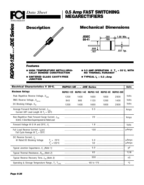
Description Featuresn HIGH TEMPERATURE METALLURGI-CALLY BON DED CON STRUCTION n SIN TERED GLASS CAVITY-FREE JUN CTIONMechanical DimensionsElectrical Characteristics @ 25o C.Maximum RatingsPeak Repetitive Reverse Voltage...V RRM RMS Reverse Voltage...V R(rms)DC Blocking Voltage...V DCRGP02-12E . . . -20E SeriesAverage Forward Rectified Current...I F(av)Current 3/8" Lead Length @ T A = 55°C Non-Repetitive Peak Forward Surge Current...I FSM8.3mS, ½ Sine Wave Superimposed on Rated Load Forward Voltage @ 0.1A and 25°C...V F DC Reverse Current...I R@ Rated DC Blocking VoltageT A=25°C T A =125°CTypical Junction Capacitance...C J (Note 1)Typical Thermal Resistance...R θJA (Note 2)Typical Reverse Recovery Time...t RR (Note 3)Operating & Storage Temperature Range...T J , T STRGPage 6-38.............................................0.5............................................................................................20............................................................................................ 1.8............................................................................................100............................................................................................ 5.0............................................................................................50............................................................................................ 5.0............................................................................................65............................................................................................300...............................................Volts Volts Volts UnitsR G P 02-12E . . . -20E S e r i e sAmps Amps VoltsµAmpsµAmps µAmps .........................................-65 to 175..........................................pF °C / W nS °Cn 0.5 AMP OPERA TION @ T A = 55°C, WITH N O THERMAL RUN AWAY n TYPICAL I R < 0.2 µAmpRGP02-12E RGP02-14E RGP02-16E RGP02-8E RGP02-20E 1200140016001800200084098011201260140012001400160018002000Full Load Reverse Current...I R (av)Full Cycle Average @ T A = 55°CR G P O 2-12E . . . -20E S e r i e sPage 6-39Ratings at25 Deg. C ambient temperature unless otherwise specified.Single Phase Half Wave, 60 HZ Resistive or Inductive Load.For Capacitive Load, Derate Current by 20%.NOTES: 1.Measured @ 1 MHZ and applied reverse voltage of 4.0V.2.Thermal Resistance from Junction to Ambient at 3/8" Lead Length, P .C. Board Mounted.3.Reverse Recovery Condition I F = 0.5A, I R = 1.0A, I RR = 0.25A.Forward Current Derating Curv eT A = Amb ient Temperature (°C)p FTypical Rev erse CharacteristicsNon-Repetitiv ePeak Forward Surge CurrentA m p sPercent of Rated Peak VoltageTypical Instantaneous Forward CharacteristicsVoltsµA m p sTypical Junction CapacitanceReverse Voltage (Volts)Numb er of Cycles @ 60 HZA m p s。
各类贴片电容容值规格参数表

各类贴片电容容值表X7R贴片电容简述X7R贴片电容属于EIA规定的Class 2类材料的电容。
它的容量相对稳固。
X7R贴片电容特性具有较高的电容量稳定性,在-55℃~125℃工作温度范围内,温度特性为±15%。
层叠独石结构,具有高可靠性。
优良的焊接性和和耐焊性,适用于回流炉和波峰焊。
应用于隔直、耦合、旁路、鉴频等电路中。
X7R贴片电容容量范围厚度与符号对应表0201~1206 X7R贴片电容选型表1210~2225 X7R贴片电容选型表NPO COG 贴片电容容量规格表2009-07-15 16:28 阅读354 评论1 字号:大中小NPO(COG)贴片电容属于Class 1温度补偿型电容。
它的容量稳定,几乎不随温度、电压、时间的变化而变化。
尤其适用于高频电子电路。
具有最高的电容量稳定性,在-55℃~125℃工作温度范围内,温度特性为:0±30ppm/℃(COG)、0±60ppm/℃(COH)。
层叠独石结构,具有高可靠性。
优良的焊接性和和耐焊性,适用于回流炉和波峰焊。
应用于各种高频电路,如:振荡、计时电路等。
咱们把用来制造片式多层瓷介电容(MLCC)的陶瓷叫电容器瓷。
那个地址所说的瓷介确实是用电容器瓷制成的陶瓷介质。
大伙儿明白,陶瓷是一类质硬、性脆的无机烧结体。
就其显微结构而论,多数具有多晶多相结构。
其性能往往决定于其成份和结构。
当配方确信以后,可否达到预期的成效,关键取决于制造陶瓷粉料的工艺。
按其用途能够分为三类:①高频热补偿电容器瓷(UJ、SL);②高频热稳固电容器瓷(NPO);③低频高介电容器瓷(X7R、Y5V、Z5U)。
按温度系数分能够分为两类:①负温度系数电容器瓷(即高频热补偿电容器瓷);②正温度系数电容器瓷(即平常咱们常说的COG、X7R、Y5V瓷料)。
按工作频率能够分为三类:低频、高频、微波介质。
高频热补偿、热稳固电容器瓷是专供Ⅰ类瓷介电容器作介质用,其瓷料要紧成份是MgTiO3、CaTiO3、SrTiO3和TiO2再加入适量的稀土类氧化物等配制而成。
ADUM1400中文资料

Figure 1. ADuM1400 Function786-0-002 03786-0-003
FUNCTIONAL BLOCK DIAGRAMS
VDD1 1 GND1 2
VIA 3 VIB 4 VIC 5 VOD 6 VE1 7 GND1 8
By avoiding the use of LEDs and photodiodes, iCoupler devices remove the design difficulties commonly associated with optocouplers. The typical optocoupler concerns regarding uncertain current transfer ratios, nonlinear transfer functions, and temperature and lifetime effects are eliminated with the simple iCoupler digital interfaces and stable performance characteristics. The need for external drivers and other discretes is eliminated with these iCoupler products. Furthermore, iCoupler devices consumes one-tenth to one-sixth the power of optocouplers at comparable signal data rates.
2 ns max pulse-width distortion 2 ns max channel-to-channel matching High common-mode transient immunity: >25 kV/μs Output enable function Wide body 16-lead SOIC package, Pb-free models available Safety and regulatory approvals UL recognition: 2500 V rms for 1 minute per UL 1577 CSA component acceptance notice #5A VDE certificate of conformity
GN16中文资料
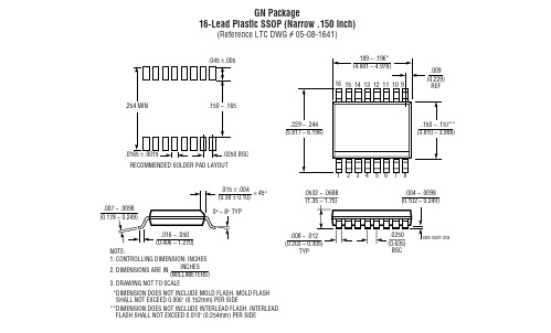
.045 ±.005 .386 – .393* (9.804 – 9.982) 28 27 26 25 24 23 22 21 20 19 18 17 1615 .033 (0.838) REF
.254 MIN
.150 – .165 .229 – .244 (5.817 – 6.198) .150 – .157** (3.810 – 3.988)
.229 – .244 (5.817 – 6.198) .254 MIN .150 – .165
.150 – .157** (3.810 – 3.988)
1 .0165 ± .0015 RECOMMENDED SOLDER PAD LAYOUT .015 ± .004 × 45° (0.38 ± 0.10) .0075 – .0098 (0.19 – 0.25) .016 – .050 (0.406 – 1.270) NOTE: 1. CONTROLLING DIMENSION: INCHES INCHES 2. DIMENSIONS ARE IN (MILLIMETERS) 3. DRAWING NOT TO SCALE *DIMENSION DOES NOT INCLUDE MOLD FLASH. MOLD FLASH SHALL NOT EXCEED 0.006" (0.152mm) PER SIDE **DIMENSION DOES NOT INCLUDE INTERLEAD FLASH. INTERLEAD FLASH SHALL NOT EXCEED 0.010" (0.254mm) PER SIDE 0° – 8° TYP .0532 – .0688 (1.35 – 1.75) .0250 BSC
G16用户手册说明书
GSM communicator G16USER MANUALUAB “TRIKDIS”Draugystės str. 17,LT-51229 KaunasLITHUANIAE-mail:***************Webpage: www.trikdis.ltContentsSAFETY REQUIREMENTS (2)DESCRIPTION (3)L IST OF COMPATIBLE CONTROL PANELS (3)S PECIFICATIONS (4)C OMMUNICATOR BOARD (4)P URPOSE OF TERMINALS (4)L IGHT INDICATION OF OPERATION (5)B EFORE YOU BEGIN (5)CONNECT G16 TO TRIKDISCONFIG (5)S TATUS BAR DESCRIPTION (6)SET OPERATION PARAMETERS (7)S YSTEM SETTINGS WINDOW (7)ARC REPORTING WINDOW→ARC REPORTING TAB (7)ARC REPORTING WINDOW→S ETTINGS TAB (8)U SER REPORTING WINDOW →P ROTEGUS SERVICE TAB (8)U SER REPORTING WINDOW →SMS&C ALL R EPORTING TAB (9)U SER REPORTING WINDOW →R EMOTE CONTROL TAB (9)3.6.1SMS commands list (9)SIM CARD WINDOW (10)E VENT SUMMARY WINDOW (10)PHYSICAL INSTALLATION PROCESS (11)I NSERT SIM CARD INTO THE HOLDER (11)I NSTALL THE COMMUNICATOR INTO A MOUNTING CASE. (11)W IRING DIAGRAMS (12)4.3.1Input connection (12)PROGRAM SECURITY CONTROL PANEL TO USE G16 DIRECT CONTROL FEATURE (13)ADD COMMUNICATOR IN PROTEGUS (13)TEST COMMUNICATOR PERFORMANCE (14)MANUAL FIRMWARE UPDATE (14)Safety requirementsThe security alarm system should be installed and maintained by qualified personnel.Prior to installation, please read carefully this manual in order to avoid mistakes that can lead to malfunction oreven damage to the equipment.Disconnect power supply before making any electrical connections.Changes, modifications or repairs not authorized by the manufacturer shall void your rights under the warranty.Please act according to your local rules and do not dispose of your unusable alarm system or itscomponents with other household waste.DescriptionCommunicator G16 is intended to upgrade compatible intruder alarm panels for event signalling via cellular network.Communicator transmits full event information to Alarm Receiving Centre.Customers are informed about security system events in Protegus apps or with SMS messages. They can Arm/Disarm the alarm system remotely (via panel’s keyswitch zone or directly via Serial for Paradox panels ®, UTC Interlogix® (CADDX), Texecom®).FeaturesConnection ∙ Connection to control panels via: o Keypad data bus; or o Serial portCommunications ∙ Two main communication channels working simultaneously∙ Each channel has a back-up channel ∙ Connection control with ARC∙ Simultaneous event reporting to ProtegusMobile/Web application, allowing user to remotely monitor and control its alarm system ∙ Event messages are transmitted in Contact ID codes ∙ Event reporting via SMS messages to four different users in user friendly SMS messages∙ Remote Arm/Disarm feature with Paradox, Texecom and UTC Interlogix security control panels. Inputs and outputs∙1 selectable type input: NC, NO, NC with EOL, NO with EOL, NC with DEOL, NO with DEOL.∙2 Outputs controlled via:o Mobile/Web application or o SMSConfiguration∙ Quick and easy installation∙ Remote configuration and firmware updates∙ Two access levels for setting of operating parametersCommunicator board1.GSM antenna SMA connector2.Light indicators3.Frontal case opening slot4.Terminal for external connectionsB Mini-B port for communicator programming6.SIM card slot56123546Before you beginBefore you begin, make sure that you have the necessary:1) USB cable (Mini-B type) for configuration.2) At least 4 wires cable for connecting communicator to control panel. 3) CRP2 cable for connecting to Paradox panel`s Serial port. 4) Flat-head screwdriver.5) Sufficient gain GSM antenna.6) In GSM network registered standard size SIM card. 7) Particular security control panel`s installation manual. Order them separately from your local distributor.Connect G16 to TrikdisConfigCommunicator can be configured using TrikdisConfig software for MS Window OS via USB cable or remotely. 1) Download TrikdisConfig from (in search field type TrikdisConfig ), and install it. 2) Connect the communicator to TrikdisConfig:Using USB cable : Carefully open the casing with flat-head screwdriver as shown below:a) Insert screwdriver into the slot (red arrow). (it is unnecessary to put in screwdriver`s head to the bottom ofthe casing).b) Hold the casing`s bottom part with one hand and gently push screwdriver to the left side.c) Plug in USB cable. Run the configuration software TrikdisConfig . The software will automatically recogniseconnected communicator and will open a window for communicator configuration;Remotely: run configuration program TrikdisConfig. In section, Remote access , field Unique ID enter IMEI address of communicator (IMEI address is provided on the product package). (Optional) in the field SystemName enter the desired name to the communicator. Press Configure.3) Click Read [F4] to read the communicators parameters and enter the Administrator or Installer code in pop-upwindow. For the program to remember the code, check the box next to Remember password.Status bar descriptionOnce the communicator parameters are read, the status bar will display information about the communicator.c)Set operation parametersSystem settings windowGeneral∙Write an appropriate Object number (4 symbols hexadecimal number).∙Test period: periodic test messages will be sent according to a time interval set in this section.∙For communication with control panel, panel type must be selected in Panel type.∙To arm/disarm remotely (e.g. via PROTEGUS service) control panel through its Serial port, enable the option Remote Arm/Disarm and enter PC download password.∙PC download password – 4-digit password identifies the PC to the panel before establish communication. If the codes match, access to the control panel is granted, otherwise access is denied. (See how to program control panel in 5 Program security control panel to use G16 Direct Control feature).∙Choose an input operation type from list IN1. NC with EOL, NO with EOL, NC with DEOL, NO with DEOL type is selectable only starting from communicator version 1.14.∙Choose an output operation type from list OUT1-OUT2.∙Specify time synchronization (Communicator will use time according to selected server) and output/input parameters.AccessThe communicator G16 have two access levels for configuring the communicator:∙Administrator code - allows full access to the configuration.∙Installer code - allows limited access for installer to the configuration.ARC reporting window→ ARC reporting tabFirst and Second channels (and Backup channels)First and second channels can work in parallel, by allowing the communicator to simultaneously transmit data via both channels.∙Select communication Mode and Protocol.o If SMS reporting will be used – enter TRK encryption key and receivers phone number.∙Enter receiver`s Domain or IP address and Port.∙Choose event transmission protocol TCP or UDP.∙Enter Phone number which will receive messages (phone numbers must contain country code, for example +370xxxxxxxx, 00370xxxxxxxx, or 370xxxxxxxx).∙Backup SMS reporting number –when GPRS mode is set in the first and the first’s backup channel, only then this option becomes enabled. SMS to SMS receiver at ARC will be sent: 1) as soon as a communicator has started working for the first time and 2) after the fail of TCP/IP or UDP/IP communication via both the first and the first’s backup channel.ARC reporting window→ S ettings tabSettings∙Write Object ID in DC-09 code, if event is transferred using SIA DC-09 protocol (4-16 symbol hexadecimal number). ∙Enter required DC-09 line No.∙Enter required DC-09 receiver No.∙After a number of attempts to reconnect fails, as set in Backup reporting after field.∙It will attempt to return to the primary channel after a time, as set in Return to primary after field.∙GPRS ping period - and set time between signals in seconds (required for communication control).∙Enter required DNS addresses.User reporting window → Protegus service tabProtegus service allows users to remotely monitor and control the communicator.Protegus service allows simultaneous transmission of data to the Protegus server for Mobile/Web application. For more information about PROTEGUS service visit www.protegus.eu.Protegus service∙ Enable cloud service atUser reporting > PROTEGUS service tab.∙Enter Service code (default code – 123456), for more safety change it to six symbol code.User reporting window → SMS & Call Reporting tabReceived event and internal communicator events messages can be reported to the users mobile phones via SMS messaging and calls.∙ Each message come with an object name: enter the Object name of your choice to the text field.∙ From SMS language drop-down list select required language (SMS messages can be sent in various charactersets).∙ It is possible to choose Reporting mode , by which events will be reported to user:o Send all – reports all events, even not described, oro Send described only - the ones that has zone, areas and user names entered.∙ Message can be send up to 4 different phone numbers. List them in Phone number table (Phone numbers mustcontain country code, for example +370xxxxxxxx, 00370xxxxxxxx, or 370xxxxxxxx).∙ Information about the received events as Areas , Users and Zones are coded in digits. Each of them can be namedand the given names will be used in SMS messages sent to the users. Write your chosen names into their appropriate tables.∙ To receive event messages, specify which CID events will be reported. Also, can be selected which phonenumbers receives (SMS/Call) notifications about the events.User reporting window → Remote control tabRemote control∙ Answers to the SMS commands can be customised in SMS answer text field.∙List a phone number for remote control to a table Phone numbers for remote control. SMS text, that user receives after sending a command (to receive an SMS answer message, the user access code must be correct).3.6.1 SMS commands listSMS Commands are used to remotely control the communicator .As access code use “Administrator code” or “Installer code”, “_” represents a space. SMS command structure: AccessCode_Command_Data .For the example purposes access code is 123456.To receive information about the communicator:“123456 INFO”To turn on the output OUT1:“123456 OUTPUT1 ON”To turn on the output OUT1 for 3 seconds:“123456 OUTPUT1 PULSE=0003”SIM card windowEnsure that the SIM card is working, before using it.If GPRS or 3G communication is required, ensure mobile data service is enabled.For information, how to enable this service please contact your GSM service provider.SIM card∙Enter SIM card PIN, APN.∙If it is required enter GSM network name and password in fields Login, Password.∙Forbid connection when roaming detected (use it when security system is installed near country border, this will ensure that communicator would not connect wrong GSM network).Event summary windowThe communicator can generate periodical test messages.To enable globally periodical test messages and set the period time, navigate to System settings → General → Test period. Time is set in day(s) and hours (Maximum 7 days).Local changes of periodical test messages can be done in Event summary window:∙Test and other internal events can be enabled/disabled and their Contact-ID number can be customised.3.9 To write new parameters to the communicator, click Write [F5].3.10 Disconnect communicator:∙ Click Disconnect to disconnect from roles (installer or admin) while communicator is connected via USB cable to computer.∙If a configuration is done via USB cable, unplug the USB cable, click Disconnect to go back to first window.Physical installation processInsert SIM card into the holdera)SIM card must be already registered to the GSM network, if GPRS communication will be used, ensure toenable mobile data service.b) To configure the communicator remotely, insert a SIM card with the PIN code request function disabled.Install the communicator into a mounting case. If the screw mounting will be used:a)Close the communicator’s case.b)Then fix the bottom part to its place with screws and place the PCB board back into case.a)Remove the PCB board from the case bottom part;4)Wiring diagramsFollowing provided schematics connect the control panel, sensors and output connections.DSC PARADOXTEXECOM CADDX4.3.1Input connectionThe communicator contains one input terminal (IN1) for connection of sensors. For setting the input connection type see 3.1 General system settings. NC with EOL, NO with EOL, NC with DEOL, NO with DEOL type is selectable only fromNC, Normally Closed Normally closed circuit with end of line resistor and tamper3,3k – 5,5k -Alarm; Open - TamperINx COMCOMINx COMINx COM INx COMCOM2,2k – Restore3,3k - 5,5k - Restore; Open - Tamper4.4 Connect a DC power supply. Program security control panel to use G16 Direct Control featurePARADOXThe PC download password is not set as default parameter in Paradox control panel. To set this password you need to perform following actions, by using PARADOX keypad:For MAGELLAN, SPECTRA series: enter the cell [9][1][1] and write in 4-digit password, this password must be the same as in the communicator G16.For DIGIPLEX EVO series: enter the cell [3][0][1][2] and write in 4-digit password, this password must be the same as in the communicator G16.TEXECOMUse Texecom software Wintex to program control panel. To enable Direct Control feature:1) Program UDL passcode – 4-digit password , in Communication Options window, tab Options.2) Make sure control panel UDL passcode matches with communicator G16 PC download password. Also, UDL passcode can be programed using keypad:1) Enter Programing menu from the keypad, by entering 4-digit Engineers code, press [Menu] button and then button[9].2) Enter [7] [6], and option [2], now enter 4 – digit passcode (matching G16 PC download password). 3) Press [Yes] and leave programing menu, by pressing [Menu] button.UTC INTERLOGIX (CADDX)To enable Direct control of Caddx, G16 should be wired to Caddx control panel and power supply turned on and follow steps bellow:1) Ensure that, in TrikdisConfig Caddx control panel is selected. 2) Using keypad enter programming mode:a. Press [*][8] [9][7][1][3] and enter device number [7][2][#],b. Exit programming mode by pressing [Exit].3) Now control panel automatically will find communicator G16.Add communicator in ProtegusProtegus service is a Web Service for remote intrusion or fire alarm self-monitoring, and control of both Trikdis and 3rd party devices via Web, iOS or Android apps. Android Google play store:https:///store/apps/details?id=lt.apps.protegus&hl=lt Apple App store:https:///us/app/protegus-smart-security/id1092492126?mt=8 1) Log in or sign in to www.protegus.eu .INx COM COM INx COM COM2) Add the system to the Protegus: press “Select system ”; next “Add new system +”, and enter the required data asshown below (you can skip fields “Name”, “Address” and fill it later).3) (Optional) If you will use remote arm/disarm feature, in Protegus main window, choose “Settings” tab and then tickthe checkbox: “Arm/Disarm with PGM”.Test communicator performanceAfter configuration and installation is complete, perform a system test:1. Check network connection (Light indication): sufficient GSM signal strength is level 5 (five yellow flashes ofindicator Network). Sufficient 3G signal strength is level 3 (three yellow flashes of indicator Network). If red trouble light flashes 5 times, search for another place to leave communicator.2. Activate an event in the control panel, and make sure that the event arrives to the alarm receiving centre or isreceived in the mobile application.3. To test communicator input, activate it and make sure that the correct messages arrives to recipients.4. To test the communicator outputs, please activate them remotely and make sure that the correct messagesarrives to recipients, and output activates as it should.5. To test Direct control feature, using Protegus service Arm/Disarm system, check if commands were performed.6. Carry out alarm signalling tests to make sure that the alarm receiving centre receives the signals correctly.Manual firmware updateThe communicator firmware can be updated or changed manually. After an update, all the previous communicator parameters will remain the same.When writing firmware manually, it can be changed to a newer or older version. To update: 1) Run TrikdisConfig.2) Connect the communicator via USB cable to the computer or connect to the communicator remotely. If newer firmware version exists, the software will offer to download the newer firmware version file.Enter IMEI (it can be found: on packing box;back of communicator`s housing; in TrikdisConfig as Unique ID).3)Select the menu branch Firmware .4)Press Open firmware and select the required firmware file.If you do not have the file, the newest firmware file can be downloaded by registered user from , under the download section of the G16 communicator.5) Press Update [F12].6) Wait for the prompt of update to complete. 7) Click OK in the prompted window.。
金具中英文对照表
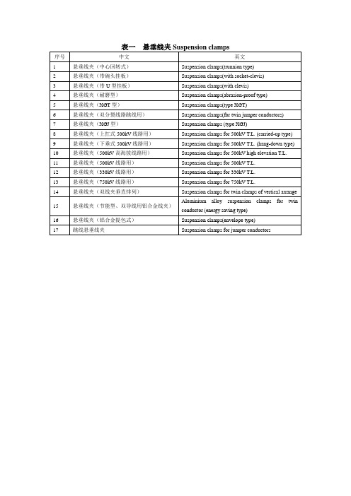
5
铝包钢绞线耐张线夹(液压型)
Strain clamps for AS. stranded wire(hydraulic compression type)
6 7 8 9 10
耐热导线耐张线夹(液压型) 耐张线夹(液压型) 铝合金绞线耐张线夹(液压型) 耐张线夹(爆压型) 铝包钢芯铝绞线耐张线夹(液压型)
12
13
表三
序号 1 2 3 4 5 6 7 8 9 10 11 12 13 14 15 16 17 18 19 20 21 22 23 24 25 26 27 28 29 30 31 32 33 34 35 36 37 38 39 40 中文 球头挂环(Q 型、QP 型) 球头挂环(QH 型) 球头挂环(Q 型) 球头挂环(QB 型) 碗头挂板(W 型) 碗头挂板(WS 型) 碗头挂板(加长 WS 型) 碗头挂板(WH 型) 碗头挂板(WSY 型) 碗头挂板(W 型) U 型挂环 U 型挂环(UN 型) U 型挂环(UF 型) 加强型 U 型挂环(UJ 型) 延长环(PH 型) 直角挂环(ZH 型) 拉杆(YL 型) 拉杆(YLP 型) 挂板(Z 型) 挂板(ZS 型) 挂板(ZBS 型) 挂板(ZBS 型悬垂用) 挂板(PS 型) 挂板(PD 型) 挂板(P 型) 挂板(UB 型) 支撑架(ZCJ 型) 挂板(UB 型悬垂用) 耳轴挂板(R 型) 避雷线悬重吊架(BD 型) U 型螺丝 调整版(DB 型) 挂点金具(GD 型) 调整板(PT 型) 牵引板(QY 型) 联板(L 型) 联板(LF 型) 联板(LS、L、LF 型) 联板(LL 型) 联板(LJ 型)
悬垂线夹(双分裂线路跳线用) 悬垂线夹(XGJ 型) 悬垂线夹(上扛式 500kV 线路用) 悬垂线夹(下垂式 500kV 线路用) 悬垂线夹(500kV 高海拔线路用) 悬垂线夹(500kV 线路用) 悬垂线夹(330kV 线路用) 悬垂线夹(750kV 线路用) 悬垂线夹(双线夹垂直排列) 悬垂线夹(节能型、双导线用铝合金线夹) 悬垂线夹(铝合金提包式) 跳线悬垂线夹
FR16中文资料
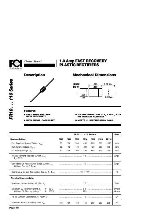
°C
Volts
............................................. 5.0 ............................................... µAmps ............................................. 100 ............................................... µAmps ............................................. 1 5 ............................................... 150 150 150 150 250 500 500 pF ns
Units
Volts Volts Volts Amps
............................................. 1.0 ...............................................
............................................. 5 0 ...............................................
1
1
10
100
1000
Number of Cycles @ 60 Hz
Typical Instantaneous Forward Characteristics 10 Forward Current (A) 100 50
给水用聚乙烯(PE)孔网骨架塑钢复合稳态管

guiICS 91.140P 45团体标准T/CECSXXXXX—202X给水用聚乙烯(PE)孔网骨架塑钢复合稳态管Steel wire mesh reinforced polyethylene plastic stable composite pipe forwater supply(征求意见稿)202X-XX-XX发布202X-XX-XX实施目次目次 (I)前言 ........................................................................................................................................ I II 1范围 (4)2规范性引用文件 (4)3术语和定义 (5)4符号和缩略语 (5)4.1符号 (5)4.2缩略语 (5)5材料 (6)5.1概述 (6)5.2原材料性能 (6)5.3钢丝 (6)6管材分类与标记 (7)6.1管材分类 (7)6.2标记 (7)7管材结构与连接方式 (7)7.1管材结构 (7)7.2连接方式 (8)8要求 (8)8.1颜色 (8)8.2外观 (8)8.3规格尺寸 (8)8.4静液压强度与爆破压力 (10)8.5物理力学性能 (10)8.6卫生性能 (11)8.7电熔承口管件的熔接强度 (11)9试验方法 (11)9.1试样的预处理 (11)9.2颜色和外观检查 (11)9.3尺寸测量 (11)9.4静液压强度与爆破试验 (12)9.5物理力学性能试验 (12)9.6卫生性能的测定 (12)9.7电熔承口管件的熔接强度 (12)10检验规则 (12)10.1组批 (12)10.2尺寸分组 (13)10.3出厂检验 (13)10.4型式检验 (13)10.5判定规则 (14)11标志、包装、运输与贮存 (14)11.1标志 (14)11.2包装 (14)11.3运输 (14)11.4贮存 (14)附录A(规范性附录)管件承口连接示意图、承口端连接尺寸要求 (15)附录B(规范性附录)管材压力折减系数 (19)附录C(资料性附录)管材内径外径尺寸对照表 (20)2T/CECS×××××—202×前言本文件按照GB/T 1.1—2020的规则起草。
IPC挠性印制电路用的挠性覆金属箔绝缘材料.

IPC-4204挠性印制电路用的挠性覆金属箔绝缘材料IPC-42042002.05内容目录1 范围...........................................1 3.4.2 胶粘剂.. (5)1.1 分类系统..................................1 3.4.3 覆金属 (5)1.1.1 非专用符号..............................1 3.4.4 片材 (5)1.1.2 专用符号..................................1 3.4.5 卷材.. (5)1.1.2.1 基膜类型................................1 3.5 外观要求.. (5)1.1.2.2 增强方式.................................1 3.5.1 标志 (5)1.1.2.3 增强类型..................................1 3.5.2 皱纹、折痕、条纹和划痕 (5)1.1.2.4 基膜厚度...................................1 3.5.3 杂夹物.. (6)1.1.2.5 胶粘剂类型................................1 3.5.4 空洞.. (6)1.1.2.6 胶粘剂厚度.................................2 3.5.5 孔洞、撕裂和分层.. (6)1.1.2.7 覆金属........................................2 3.6 尺寸要求 (6)1.1.2.7.1 规格单号...................................2 3.6.1 片材宽度和长度. (6)1.1.2.7.2 金属箔......................................2 3.6.2 卷材宽度. (6)1.1.2.7.3 金属箔类型................................2 3.6.3 卷材长度. (6)1.1.2.7.4 金属箔等级...............................2 3.6.4 绝缘厚度 (6)1.1.2.7.5 标称覆金属厚度..........................3 3.6.5 胶粘剂厚度 (6)1.1.2.7.6 粘结增强处理.............................3 3.6.6 金属箔厚度 (6)1.2 鉴定................................................3 3.7 物理性能要求 (7)1.3 质量一致性......................................3 3.7.1 尺寸稳定性.. (7)1.4 材料特性.........................................3 3.7.2 剥离强度.. (7)1.5 新材料............................................3 3.7.2.1 接收态剥离强度 (7)2 引用文件...........................................3 3.7.2.2 浮焊后剥离强度.. (7)2.1 IPC................................................4 3.7.2.3 温度循环后剥离强度.. (7)2.2 美国材料测试与材料协会(ASTM).....4 3.7.3 起始撕裂强度. (7)2.3 UL标准..........................................4 3.7.4 扩展撕裂强度. (7)2.4 NCSL国际标准................................4 3.7.5 弯曲疲劳. (7)2.5 ISO................................................4 3.7.6 低温可挠性. (7)3 要求................................................4 3.8 化学性能要求. (7)3.1 术语和定义.....................................4 3.8.1 耐化学性. (7)3.1.1 鉴定检验......................................4 3.8.2 耐浮焊性. (7)3.1.2 质量一致性检验.............................4 3.8.3 可焊性. (7)3.1.3 用户检验批..................................4 3.9 电性能要求.. (7)3.1.4 卖方检验批...................................4 3.9.1 介电常数. (7)3.1.5 结构相似的组成.............................4 3.9.2 介质损耗角正切. (7)3.1.6 空洞............................................5 3.9.3 体积电阻率(湿热). (7)3.1.7 杂夹物........................................5 3.9.4 表面电阻(湿热) (7)3.2 规格单...........................................5 3.9.5 介电强度 (7)3.3抵触..............................................5 3.10 环境性能要求 (7)3.4 材料..............................................5 3.10.1 耐霉性. (7)3.4.1 基膜...........................................5 3.10.2 吸水率 (8)3.10.3 阻燃性...................................8 4.9.4 参数能力评定 (11)3.10.4 使用温度................................8 4.9.5 参数分析 (11)3.10.5 耐湿性和绝缘电阻...................8 4.9.6质量一致性放宽检验.. (11)3.11 制造质量..................................8 4.9.6.1 放宽检验的条件. (11)4 质量保证条款................................8 4.9.6.2 放宽检验样本大小. (16)4.1 检验职责...................................8 4.9.6.3 检查控制计划的条件 (16)4.2 检验设备和检测设施...................8 5 交货准备 (16)4.3 标准实验室条件.........................8 5.1 包装. (16)4.4 容许偏差..................................8 6 说明 (16)4.5 检验分类..................................8 6.1 订单资料. (16)4.6 材料检验..................................8 6.2 特殊化学品暴露. (16)4.7 鉴定检验..................................8 6.3 参考 (16)4.7.1 特性检验………………………….8 图4.7.2 频度.....................................8 图4-1控制计划. (12)4.8 质量一致性检验........................8 图4-2 流程和控制/检验点图 (13)4.8.1 产品交货检验.........................9 图4-3 过程参数相关图. (14)4.8.2 样本单位...............................9 图4-4 质量一致性放宽检验图. (15)4.8.3 A组检验…………………………..9 表4.8.3.1 抽样方案.............................9 表1-1 基膜类型符号 (1)4.8.3.2 失效..................................10 表1-2 增强方式符号. (1)4.8.3.3 用户抽样方案......................10 表1-3 增强类型符号.. (2)4.8.3.4 拒收批...............................10 表1-4 基膜和胶粘剂厚度符号.. (2)4.8.4 B组检验...............................10 表1-5 胶粘剂类型符号.. (2)4.8.4.1 抽样方案............................10 表1-6 金属箔等级符号. (2)4.8.4.2失效..................................10 表1-7 铜箔厚度符号 (3)4.8.4.3 材料的不合格.....................10 表3-1 基膜标称厚度的允许偏差 (6)4.8.5 C组检验..............................10 表3-2 胶粘剂标称厚度的允许偏差. (6)4.8.5.1 抽样方案............................10 表4-1 试验方法频度. (9)4.8.5.2失效..................................10 表4-2 片材A组和B组检验抽样方案. (9)4.8.5.3 材料的不合格.....................10 表4-3 卷材A组和B组检验抽样方案. (9)4.9 统计过程控制(SPC) (10)4.9.1 参数标识 (11)4.9.2 参数诊断 (11)4.9.3 参数控制 (11)2002.05 IPC-4204挠性印制电路用的挠性覆金属箔绝缘材料1 范围本标准规定了用作挠性印制电路和挠性扁平电缆的挠性覆金属箔绝缘材料的分类系统、鉴定检验和质量一致性检验的要求。
316截止阀

316截止阀据预计,2010年前后,经过产业大规模整合和产品结构调整,国内中小型装置将逐渐淡出市场,而中石化和中石油两大巨头通过扩能和技术手段将使竞争力陡升,仍将主导国内聚丙烯市场。
关键词:聚丙烯齿轮仪器产品紧缺零部件质量有待加强一、产品[直流式对焊截止阀]的详细资料:产品名称:直流式对焊截止阀产品特点:高温高压直流式对焊截止阀,直流式对焊截止阀,高温高压截止阀二、主要零件材料:零件名称材料牌号阀体WCB WC6 WC9活塞A105 WC6 WC9 阀盖25 12Cr1MoV A阀杆1Cr17Ni2 20Cr1Mo1V1A密封环05F 05F 柔性石墨四开环1Cr13 20CrMOIVIA填料BSP-600 BSP-600支架WCB WCB阀杆螺母ZQAL9-4 ZQAL9-4三、应用规范:1、设计制造JB3595规定2、结构长度按JB3595规定或按用户要求3、连接端按JB3595规定或按用户要求4、阀门检查和试验按JB3595规定四、订货号、尺寸和重量:公称通径DN(mm)尺寸(mm)重量(Kg)L D1 Do H Lo L1PN32(320)J565Y-320V型80 390 64 120 750 - - 121 100 480 108 185 870 - - 212 125 533 132 218 995 - - 312 150 610 166 245 1205 - - 510 175 750 175 278 1565 - - 708 200 762 200 290 1670 - - 980 225 850 108 310 1705 - - 1060 250 914 248 348 1870 - - 1380 300 1041 300 430 2335 - - 2824 P54(140)J565Y-P54140V型80 390 64 120 750 - - 130 100 480 108 185 870 - - 212 125 580 132 218 995 - - 312 150 630 166 245 1205 - - 510 175 750 175 278 1565 - - 708 200 771 200 290 1670 - - 980 225 850 108 310 1705 - - 1060 250 930 248 348 1870 - - 1380 300 1060 300 430 2335 - - 2824 说明:凡按用户要求的须在合同中写明。
预绞式金具产品

企业精神。
目录
Table of contents
预绞式耐张线夹 ...................................................................................................................................................................................... 4 Preformed Tension Set ..................................................................................................................................................................... 4
预绞式电力金具产品
Preformed Line Products For Overhead Line Helical Fittings
东莞市海力线路器材有限公司
Dong Guan HaiLi Line Products Co. Ltd.
地址:广东东莞市厚街赤岭பைடு நூலகம்业区阳明路
电话:5 88035417
传真:0
公司简介
东莞市海力线路器材有限公司是一家专业从事预绞式电力金具和光缆金具开 发、生产的专业公司。技术力量雄厚,技术团队有近十年预绞丝金具开发、生产 经验。公司借鉴国外先进技术,自主开发出行业领先的全自动预绞丝生产线设备, 生产效率高,工艺技术先进。产品质量可靠,从原材料到产品出厂都经过严格的 质量检验流程,保证产品质量稳定可靠。我们的目标是做中国最值得信赖的预绞 丝金具产品制造商。
【尚择优选】XX输电线路常用金具图文及参数.doc

1悬垂线夹用于悬挂或支托导、地线于绝缘子串上(悬垂型杆塔)及悬挂跳线于绝缘子串上的(耐张型杆塔)的金具。
中心回转式悬垂线线夹及参数微信号:shudianRianlu带碗头挂板悬垂线线夹及参数公众号:输配电线路带U型挂板悬垂线线夹及参数微信号:shudianRianlu加强型悬垂线线夹及参数提包式悬垂线线夹及参数(铝合金)双线夹垂直排列悬垂线线夹及参数微信号:shudianRianlu预绞式悬垂线线夹现行规范为《架空线路用预绞式金具技术条件》(DL/T763-20RR)。
2耐张线夹耐张线夹,用于固定导线,以承受导线张力,并将导线挂至耐张串组或杆塔上的金具。
主要用在耐张、转角、终端杆塔的绝缘子串上。
公众号:输配电线路螺栓型耐张线线夹及参数液压型耐张线线夹及参数微信号:shudianRianlu预绞式耐张线线夹及部分参数3球头挂环球头环是用于连接绝缘悬垂片的铁质圆形装置。
球头挂环及参数4碗头挂板碗头挂板用来连接球窝型绝缘子下端的球头。
W型碗头挂板及参数公众号:输配电线路WS型碗头挂板及参数5U型挂环U型挂环是以圆钢锻制而成,用途较广,可以单独使用,也可以两个串装使用。
U型挂环及参数6U型螺栓两端分别由挂环与螺纹杆构成,与杆塔连接的U形金具。
U型螺丝及参数公众号:输配电线路7延长环用于环形金具的连接,以加长连接尺寸或转变连接方向。
延长环及参数8直角环直角环是用来连接槽型悬式绝缘子上端钢帽的连接金具。
直角环及参数9挂板挂板是一种改变连接方向的转向或者增加金具长度的连接金具。
Z型挂板及参数ZS型挂板及参数微信号:shudianRianluPS型挂板及参数公众号:输配电线路P型挂板及参数微信号:shudianRianluP型挂板及参数10调整板可调节连接长度的板形连接金具。
DB型调整板及参数公众号:输配电线路PT型调整板及参数11联板连接若干绝缘子串或将多个受力分支组装成整体的板形连接金具。
L型联板及参数微信号:shudianRianluL型联板及参数L型联板及参数微信号:shudianRianlu L型联板及参数LF型联板及参数LV型联板及参数微信号:shudianRianlu LS型联板及参数LJ型联板及参数微信号:shudianRianlu LJ型联板及参数公众号:输配电线路LL型联板及参数LK型联板及参数微信号:shudianRianluLR型联板及参数12接续管(液压)接续管,导线连接管,使用液压钳进行导线压接。
保温管用聚乙烯电热熔套

保温管用聚乙烯电热熔套(带)1 范围本标准规定了保温管道用电热熔套(带)的术语、技术要求、试验方法、检验规则及其标志、包装、运输与贮存。
标准适用于埋地保温管道保温外护层补口使用的聚乙烯电热熔套(带)。
2 规范性引用文件下列文件对于本文件的应用是必不可少的。
凡是注日期的引用文件,仅注日期的版本适用于本文件。
凡是不注日期的引用文件,其最新版本(包括所有的修改单)适用于本文件。
GB/T 1040 塑料拉伸性能试验方法GB/T 1408.1 固体绝缘材料电气强度的试验方法工频下的试验GB/T 1410 固体绝缘材料体积电阻率和表面电阻率试验方法GB/T 1633 热塑性塑料维卡软化温度(VST)的测定GB/T 3682 热塑性塑料熔体质量流动速率和熔体体积流动速率的测定GB/T 7141 塑料热空气暴露试验方法GB/T 8804.3 热塑性塑料管材拉伸性能测定第3部分聚烯烃管材GB/T 23257 埋地钢质管道聚乙烯防腐层GB/T 29046 城镇供热预制直埋保温管道技术指标检测方法GB/T 29047 高密度聚乙烯外护管硬质聚氨酯泡沫塑料预制直埋保温管及管件EN 489 District heating pipes -Preinsulated bonded pipe systems for directly buried hot water networks - Joint assembly for steel service pipes, polyurethane thermal insulation and outer casing of polyethyleneEN ISO 6721-1 Plastics — Determination of dynamic mechanical properties — Part 1: General principlesEN ISO 6721-4 Plastics — Determination of dynamic mechanical properties — Part 4: Tensile vibration — Non-resonance methodNACE RP0303 Standard Recommended Practice Field-Applied Heat-Shrinkable Sleeves for Pipelines:Application,Performance,and Quality Control3 术语和定义GB/T 23257、GB/T 29046、GB/T 29047 界定的以及下列术语和定义适用于本文件。
常用模具材料硬度一览表 (version 1)
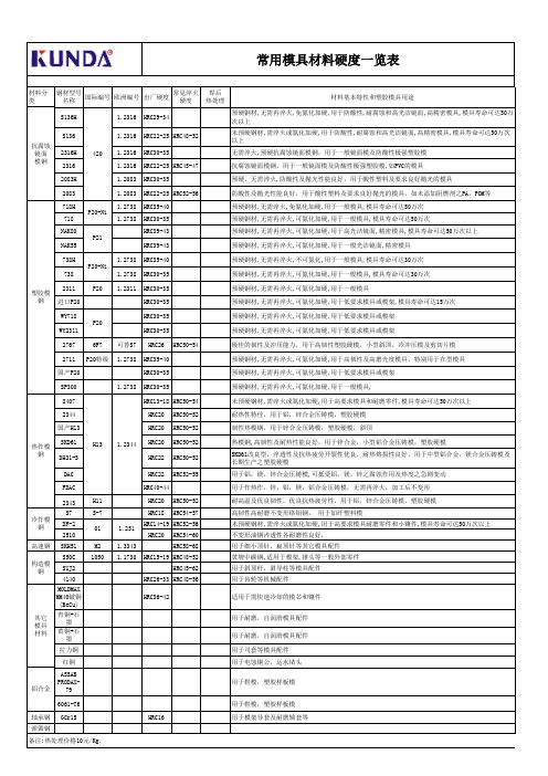
韧性热模钢,用于锌合金压铸模,塑胶硬模,斜顶
SKD61 热作模
H13
1.2344 HRC20 HRC50-52
钢
DH31-S
HRC22 HRC50-52
DAC
HRC22 HRC52-55
热模钢,高韧性及耐热性能良好,用于锌合金,小型铝合金压铸模,塑胶硬模
SKD61改良型,淬透性及抗热疲劳开裂性优良,耐热熔损性良好,用于中型铝合金,镁合金压铸模及 长期生产之塑胶硬模
738H 738
P20+Ni
1.2738 HRC35-40 1.2738 HRC30-35
预硬钢材,无需再淬火,不可氮化,用于一般模具,模具寿命可达30万次 预硬钢材,无需再淬火,可氮化加硬,用于一般模具,模具寿命可达30万次
2311
P20
塑胶模
钢 进口P20
1.2311 HRC30-35 HRC30-35
常用模具材料硬度一览表材料分类国际编号欧洲编号出厂硬度材料基本特性和塑胶模具用途s136h42012316hrc2934s13612316hrc2225hrc48522316h12316hrc3035231612316hrc2225hrc45472083h12083hrc3035208312083hrc2225hrc5256塑胶模钢718hp20ni12738hrc354071812738hrc3035nak80p21hrc3943nak55hrc3943738hp20ni12738hrc354073812738hrc30352311p2012311hrc3035hrc3035wy718p20hrc3035wy2311hrc303527676f7hrc26hrc5054极佳的韧性及冲压能力用于高韧性塑胶硬模小型斜顶冷冲压模及剪切片模271112738hrc3540hrc3035sp30012738hrc30358407h1312344hrc1318hrc50542344hrc20hrc5052耐热性特佳用于铝锌合金压铸模塑胶硬模hrc20hrc5052韧性热模钢用于锌合金压铸模塑胶硬模斜顶skd61hrc20hrc5052dh31shrc22hrc5052dachrc22hrc5255fdachrc4044用于作热作锌铝镁铝合金压铸模无需再淬火加工后不变形2343h11hrc20hrc5052耐高温及优良韧性优良抗热疲劳性用于铝锌合金压铸模塑胶硬模冷作模钢s7s7hrc18hrc5457高韧性高耐磨不变形铬钼钢用于加纤塑料模df2011251hrc1419hrc52562510hrc20hrc5460不变形油钢淬透性各耐磨性良好高速钢skh51m213343hrc5868用于细小顶针扁顶针等其它模具配件构造模钢s50c105011730hrc1519hrc4852suj2hrc4562用于斜顶杆斜导柱等模具配件4140hrc2633hrc4856用于齿轮等机械配件hrc3642适用于需快速冷却的模芯和镶件用于耐磨自润滑模具配件用于耐磨自润滑模具配件拉力铜用于司套等模具配件红铜铝合金用于鞋模塑胶样板模6061t6用于鞋模塑胶样板模轴承钢gcr15hrc16用于模架导套及耐磨轴套等弹簧钢钢材型号名称常见淬火硬热处理抗腐蚀镜面预硬钢材无需再淬火免氮化加硬用于防酸性耐腐蚀和高光洁镜面高精密模具模具寿命可达50万次以上未预
- 1、下载文档前请自行甄别文档内容的完整性,平台不提供额外的编辑、内容补充、找答案等附加服务。
- 2、"仅部分预览"的文档,不可在线预览部分如存在完整性等问题,可反馈申请退款(可完整预览的文档不适用该条件!)。
- 3、如文档侵犯您的权益,请联系客服反馈,我们会尽快为您处理(人工客服工作时间:9:00-18:30)。
Electrical Characteristics(23 )
Part Number FRG300-16 FRG400-16 FRG500-16 FRG600-16 FRG700-16 FRG800-16 FRG900-16 FRG1000-16 FRG1100-16 FRG1200-16 FRG1400-16 Hold Trip Max.time Maximum Current Current to trip Current IH, A 3.0 4.0 5.0 6.0 7.0 8.0 9.0 10.0 11.0 12.0 14.0 IT, A 5.1 6.8 8.5 10.2 11.9 13.6 15.3 17.0 18.7 20.4 23.8 at 5x IH 2.0 3.5 3.6 5.8 8.0 9.0 12.0 12.5 13.5 16.0 20.0 I MAX, A 100 100 100 100 100 100 100 100 100 100 100 Rated Voltage V MAX, Vdc 16 16 16 16 16 16 16 16 16 16 16
Pcs /Bag
500 300 300 300 200 200
Reel/Tape
3k 3k 3k 3k 1.5k -------
P/N
FRG900-16 FRG1000-16 FRG1100-16 FRG1200-16 FRG1400-16
Pcs /Bag
200 100 100 100 100
Reel/Tape
C Typical 5.1 5.1 5.1 5.1 5.1 5.1 5.1 5.1 5.1 10.2 10.2
D Minimum 7.6 7.6 7.6 7.6 7.6 7.6 7.6 7.6 7.60 3.0 3.0 3.0 3.0 3.0 3.0 3.0 3.6 3.4
200%
150%
100%
50%
0% -40 -20 0 20 40 60 80
Ambient Temperature (C)
2
DB LECTRO Inc., 3600-I, boulevard Matte, Brossard, QC J4Y 2Z2
元器件交易网
Radial Leaded PTC FRG Series
Part A B Number Maximum Maximum FRG300-16 7.1 11.0 FRG400-16 8.9 12.8 FRG500-16 10.4 14.3 FRG600-16 10.7 17.1 FRG700-16 11.2 19.7 FRG800-16 12.7 20.9 FRG900-16 14.0 21.7 FRG1000-16 16.5 24.1 FRG1100-16 17.5 26.0 FRG1200-16 17.5 28.0 FRG1400-16 27.9 27.9
Insulating coating:Flame retardant epoxy ,meet UL-94V-O requirement.
1
DB LECTRO Inc., 3600-I, boulevard Matte, Brossard, QC J4Y 2Z2
元器件交易网
Typical Time-To-Trip at 23
A=FRG300-16 B=FRG400-16 C=FRG500-16 D=FRG600-16 E=FRG700-16 F=FRG800-16 G=FRG900-16 H=FRG1000-16 I =FRG1100-16 J=FRG1200-16 K=FRG1400-16
元器件交易网
Radial Leaded PTC FRG Series
FUZETEC
Application: Wide variety of electronic equipment Product Features: Very high hold current, Solid state Radial-leaded product ideal for up to 16Vdc Operation Current: 3 A~14A Maximum Voltage: 16V Temperature Range: -40 to 85 Agency Approvals: UL(E211981), C-UL(E211981),
Radial Leaded PTC FRG Series
FRG Product Dimensions (millimeters)
Lead Size Lead Size
FUZETEC
FRG300-16~FRG1100~16 FRG1200-16~FRG1400-16 0.81 20AWG mm Diameter 1.0 18AWG mm Diameter
IH=Hold current-maximum current at which the device will not trip at 23 still air. IT=Trip current-minimum current at which the device will always trip at 23 still air. V MAX=Maximum voltage device can withstand without damage at its rated current. I MAX= Maximum fault current device can withstand without damage at rated voltage (V max). Pd=Typical power dissipated from device when in the tripped state in 23 still air environment. RMIN=Minimum device resistance at 23 . R1MAX=Maximum device resistance at 23 , 1 hour after tripping . Physical specifications: Lead material: FRG300~FRG1100 Tin plated copper,20 AWG. FRG1200~FRG1400 Tin plated copper,18 AWG. Soldering characteristics:MIL-STD-202, Method 208E.
F RG300 09AB
Part Marking System
F RG Fuzetec Logo Part Identification Product Family
Example
Date Code/Lot Number
Standard Package
P/N
FRG300-16 FRG400-16 FRG500-16 FRG600-16 FRG700-16 FRG800-16
F Typical 1.2 1.2 1.2 1.2 1.2 1.2 1.2 1.2 1.2 1.4 1.4
Thermal Derating Curve
Thermal Derating Curve - FRG Series
Percent of rated hold current and trip current
FUZETEC
A 1000 100 10 1 0.1 0.01 0.001 1
B C D EFG H I
J
K
Time-to-Trip (S)
10
100
Fault Current (A)
Part Numbering System
FRG Unencapsulated part Maximum interrupt Voltage rating Current rating
TÜV(R3-5000-4084) Typical Resistance Tolerance Power RMIN R1MAX Pd, W Ω Ω 2.3 0.034 0.105 2.4 0.020 0.063 2.6 0.014 0.044 2.8 0.009 0.033 3.0 0.006 0.021 3.0 0.005 0.018 3.3 0.004 0.015 3.3 0.003 0.012 3.7 0.003 0.010 4.2 0.002 0.009 4.6 0.002 0.008
-------------------------------
3
DB LECTRO Inc., 3600-I, boulevard Matte, Brossard, QC J4Y 2Z2
