CTDS1608C-474中文资料
口腔CT 机 CFDA信息查询-10-12
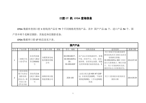
口腔X射线数字化体层摄影设备
国食药监械(准)字2014第3301031号
深圳安科高技术股份有限公司
DENTOM
由扫描架、X射线组件(PDM90P&N900X4647)、X射线管(D054)、限束器、探测器(PaxScan 2520DX)、触摸屏、电源柜、操作台、显示器组成
适用于口腔颌面X射线体层摄影诊断
产品组成:高压发生器(PROMAX 3D)、X射线管组件(PROMAX 3D)、X射线管(D-054SB-P)、限束器、平板探测器(ProMax 3D Mid、ProMax 3D、ProMax 3Ds)、传感器(Dimax3)、头颅装置(PROMAX3D)、操作台、患者支撑装置(PROMAX 3D)、重建服务器(PROMAX3D)、彩色显示器(选配)。产品性能:标称电功率均为1344W;X射线管组件(固定阳极,焦点0.5mm);X射线管电压范围均为全景54-84kV,头颅60-84kV,三维54-90kV
2014.09.04
3
便携式口腔X射线机
沪械注准20162300103
上海智普医疗器械有限公司
ZP-200B
品由主机(包括X射线限束器、防பைடு நூலகம்屏)、电源适配器和挂绳组成。
用于对牙齿X射线摄影,获得X射线影像供临床诊断。
2016.02.19
4
口腔X射线机
津械注准20152300178
邦盛医疗装备(天津)股份有限公司
供医疗机构对人口腔全颌面作体层摄片。
2014.12.22
20
口腔颌面全景X射线机
国食药监械(准)字2014第3300670号
福建梅生医疗科技股份有限公司
MSQJ2000-Ⅰ
该产品由机架、升降机构、回转机构、电气控制电路、X射线源组件(型号:MSQJ2000-Ⅰ)、X射线管(型号:D-054SB)、准直器、头部定位装置、X射线成像装置(影像接收部件类型:胶片暗盒)组成。
8XC196MC中文资料

3
元器件交易网
8XC196MC
270946 – 2
NOTE The pin sequence is correct The 64-Lead SDIP package does not include the following pins P1 4 ACH12 P2 7 COMPARE3 P5 1 INST CLKOUT
Y
Y Y Y Y
Y
Y Y Y Y Y
Y
Y
The 8XC196MC is a 16-bit microcontroller designed primarily to control 3 phase AC induction and DC brushless motors The 8XC196MC is based on Intel’s MCS 96 16-bit microcontroller architecture and is manufactured with Intel’s CHMOS process The 8XC196MC has a three phase waveform generator specifically designed for use in ‘‘Inverter’’ motor control applications This peripheral allows for pulse width modulation three phase sine wave generation with minimal CPU intervention It generates 3 complementary non-overlapping PWM pulses with resolutions of 0 125 ms (edge trigger) or 0 250 ms (centered) The 8XC196MC has 16 Kbytes on-chip OTPROM ROM and 488 bytes of on-chip RAM It is available in three packages PLCC (84-L) SDIP (64-L) and EIAJ QFP (80-L) Note that the 64-L SDIP package does not include P1 4 P2 7 P5 1 and the CLKOUT pins Operational characteristics are guaranteed over the temperature range of b 40 C to a 85 C The 87C196MC contains 16 Kbytes on-chip OTPROM The 83C196MC contains 16 Kbytes on-chip ROM All references to the 80C196MC also refers to the 83C196MC and 87C196MC unless noted
CSC-161 系列数字式线路保护装置说明书
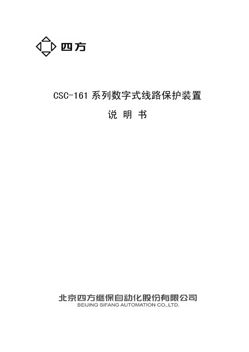
1.1 CSC-160 系列保护装置适用范围........................................................................... 1 1.2 CSC-160 系列保护装置主要特点........................................................................... 3 1.3 装置外形尺寸和安装尺寸...................................................................................... 4 1.4 装置外观.................................................................................................................. 5 1.5 装置执行的标准...................................................................................................... 5 1.6 CSC-161 系列装置的适用范围............................................................................... 5 1.7 本说明书适用范围.................................................................................................. 5
74ls160中文资料
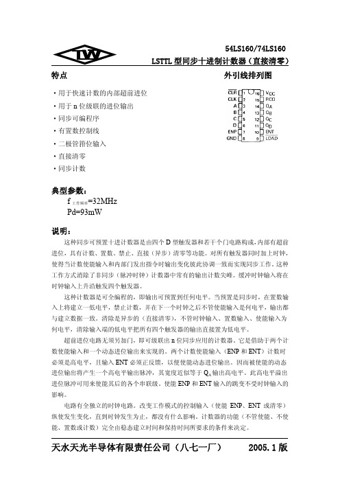
最大时钟频率
传输延迟时间 时钟 动态进位
传输延迟时间 CLK 输出 RCO
传输延迟时间 传输延迟时间
时钟 CLK
任一 Q
传输延迟时间 使能 动态进位
传输延迟时间 ENT 输出 RCO
传输延迟时间 清零 CLR 任一 Q
CL=15pF RL=2kΩ
参数值 最小 典型 最大
25 32 20 35
18 35
-100 31 32
54
参数值
单位
最小 典型 最大
-1.5 V
2.5 3.4
V
0.25 0.4 V
0.2 mA
0.1
40 μA 20
-0.8 mA
-0.4
-20
-100 mA
18 31 mA
19 32 mA
注 1:测 ICCH 时,所有输出为高电平并开路;
注 2:测 ICCL 时,所有输出为低电平并开路;
电路有全独立的时钟电路。改变工作模式的控制输入(使能 ENP、ENT 或清零) 纵使发生变化,直到时钟发生为止,都没有什么影响。计数器的功能(不管使能、不使 能、置数或计数)完全由稳态建立时间和保持时间所要求的条件来决定。
天水天光半导体有限责任公司(八七一厂) 2005.1 版
逻辑图
54LS160/74LS160 LSTTL 型同步十进制计数器(直接清零)
8 25
85
电 性 能(除特别说明外,均为全温度范围)
最小 4.5 2.0
0 25 20 20 20 20 20 20 25 3 -55
54 参数值 典型
5
最大 5.5 0.7 -400 4 25
125
单位
V V V μA mA MHz ns
videotec 2015 产品目录中文版说明书

中文产品说明书 2015 CCTV 产品DOCCTZH1507产品说明书 2015 / 修订号 1507所示的全部摄像机和镜头只用于说明, 并非随产品提供 ("ULISSE", "ULISSE COMPACT", "NXPTZ/NXPTZT", "MAXIMUS MPX/MPXT", "MAXIMUS MHX/MHXT", "NTC" 除外)。
如要获取更多信息, 请浏览产品页中的技术数据表。
未经 Videotec S.p.A书面许可, 不得将本文的全部或部分进行复制、修改或记录于文件系统, 以任何形式或者任何电子、机械或记录方式传输。
本文包含的技术规格可能会变更: Videotec S.p.A.保留变更而不事先通知的权利。
技术规格如有变更, 恕不另行通知。
重量和尺寸只作说明用途。
二月 2015. 所有旧版目录均废除。
VIDEOTEC: 辉煌的历史在近三十年,在視頻監控行業的活動,我們設計,創建並獲得專利的眾多產品監測所有類型的外部環境。
今天,我們的公司是一個最受人尊敬的供應商在同行業中,得益於我們的創新,我們的發展CCTV解決方案,保證安全性和可靠性。
遍布全球的销售和技术支持VIDEOTEC的销售和生产总部位于意大利东北部,占地1.3万平方米,另外在法国,美国,加拿大以及亚太地区设立了分部. 迄今为止,VIDEOTEC已经在全球建立了超过100家分销商的营销网络,总的来说,即使面对安防领域最复杂的行业要求,我们也能提供一整套完整的产品选型以及解决方案.产品适合于各种行业我们产品的适用范围非常广泛:从政府部门到国有或私有企业,商业部门,银行以及监狱的视频监控.在这些领域之外还有工业上的应用,比如在高温环境下或特殊的气候环境下,交通控制系统下,城市检测以及海滩和边境系统下,防止某些潜在的爆炸性事件的发生.无与伦比的品质每个VIDEOTEC的解决方案都是由我们的专业人员与国际尖端大学以及研究机构合作后的结果.这种操作模式允许我们作为行业先锋,在实验中用专业的技术以及先进的材料来创造出绝对创新的产品以及解决方案.易安装易维护我们的产品的性能是完美的,并且它的易于安装以及持久稳定性更保证了我门著重于设计的产品理念,这也是我们公司的独特标志,是我们对产品的卓越品质的一份保证.3香港內容9云台摄像机单元防爆云台摄像机单元不锈钢云台摄像机29摄像机外壳隐蔽监视摄像机防护罩防破坏摄像机防护罩防爆摄像机及其防护罩不锈钢摄像机及其防护罩447云台马达不锈钢云台遥测防爆解码器53红外/白光照明灯57视频内容分析63控制键盘矩陣视频分配器67视频传输69摄像机支架5OIL AND GAS市場INDUSTRY PLANTSTERMINALSDRILLING RIGS OIL AND GAS TANKERS PIPELINESOFFSHORE MARINEONSHORE - PERIMETER APPLICATIONSONSHORE - INTERNALAPPLICATIONS OIL AND GAS PLATFORMS67INFRASTRUCTURES AND TRANSPORTATIONCITY SURVEILLANCEBRIDGESPARKING LOTSUNDERGROUNDSAIRPORTSRAILWAYS AND STATIONSHIGHWAYSSTADIUMSTUNNELS8规格如有改变,恕不另行通知。
HT1628中文资料
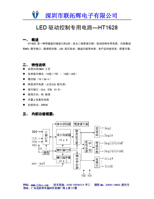
LED驱动控制专用电路---HT1628一、概述HT1628是一种带键盘扫描接口的LED(发光二极管显示器)驱动控制专用电路,内部集成有MCU数字接口、数据锁存器、LED高压驱动、键盘扫描等电路。
本产品性能优良,质量可靠。
二、特性说明�采用功率CMOS工艺�多种显示模式(10段×7位~13段×4位)�键扫描(10×2bit)�辉度调节电路(占空比8级可调)�串行接口(CLK,STB,DI/O)�振荡方式:RC振荡�内置上电复位电路�封装形式:SOP28三、内部功能框图:四、管脚定义:管脚功能定义:五、显示寄存器地址和显示模式:该寄存器存储通过串行接口从外部器件传送到HT1628的数据,地址分配如下:六、键扫描和键扫数据寄存器:为10×3bit,如下所示:键扫数据储存地址如下所示,用读指令读取,读从低位开始:七、指令说明:指令用来设置显示模式和LED驱动器的状态。
在STB下降沿后由DIN输入的第一个字节作为一条指令。
如果在指令或数据传输时STB被置为高电平,串行通讯被初始化,并且正在传送的指令或数据无效(之前传送的指令或数据保持有效)。
(1)显示模式设置:该指令用来设置选择段和位的个数(4~7位,10~13段)。
当指令执行时,显示被强制终止,同时键扫描也停止。
要重新显示,显示开/关指令“ON”必需被执行,但当相同模式被设置时,则上述情况并不发生。
上电时,设置模式为4位,14段。
(2)数据设置:该指令用来设置数据写和读(3)地址设定:该指令用来设置显示寄存器的地址。
如果地址设为0EH或更高,数据被忽略,直到有效地址被设定。
上电时,地址设为00H。
(4)显示控制:上电时,设置为脉冲宽度为1/16,显示关。
上电时,键扫停止。
八、串行数据传输格式:数据接收(写数据)数据读取:因为DOUT管脚为N管开漏输出,所以该脚要连接一个外部上拉电阻(1KΩ到10KΩ)**:读取数据时,从串行时钟CLK的第8个上升沿开始设置指令到CLK下降沿读数据之间需要一个等待时间tWAIT(最小1μS)。
NSSM016C中文资料

NSSM016C中⽂资料No. STSE-CM6044ASPECIFICATIONS FOR NICHIA CHIP TYPE FULL COLOR LEDMODEL : NSSM016CTNICHIA CORPORATION1.SPECIFICATIONS(1) Absolute Maximum Ratings (Ta=25°C)Absolute Maximum Rating Item Symbol Blue Green RedUnit Forward Current I F 35 35 50 mA Pulse Forward Current I FP 110 110 200 mA Reverse Voltage V R 5 V Power Dissipation P D 123 123 125 mW Total Power Dissipation P tot 280 mW Operating Temperature T opr -30 ~ + 85 °C Storage Temperature T stg -40 ~ +100 °C Soldering Temperature T sld Reflow Soldering : 260°C for 10sec.Hand Soldering : 350°C for 3sec.I FP Conditions : Pulse Width 10msec. and Duty 1/10 Value for one LED device (Single color).Value for total power dissipation when two and more devices are lit simultaneously.(2) Initial Electrical/Optical Characteristics (Ta=25°C)Blue Green Red Item Symbol Condition Typ.Max.Typ.Max. Typ. Max.UnitForward Voltage V FI F =20[mA] (3.2) 3.5 (3.2) 3.5 (2.1) 2.5 V Reverse Current I R V R = 5[V] - 50 - 50 - 50µA Luminous Intensity Iv I F =20[mA] (400)- (1200)- (700) - mcd x - I F =20[mA] 0.133- 0.189- 0.700 - - Chromaticity Coordinatey-I F =20[mA]0.075- 0.718- 0.299 - -Please refer to CIE 1931 chromaticity diagram.(3) Ranking(Ta=25°C)Blue Green Red Item Symbol Condition Min.Max.Min.Max. Min. Max.UnitLuminous IntensityIvI F =20[mA] 280 560 800 1600 380 1080mcdLuminous Intensity Measurement allowance is ± 10%.Color Ranks (I F =20mA, Ta=25°C)BlueRank Wx 0.139 0.129 0.113 0.1340.1450.152y 0.035 0.050 0.080 0.1050.0720.056GreenRank G0c x 0.166 0.136 0.176 0.2200.2370.201<= <=RedRRankx 0.674 0.648 0.677 0.708y 0.296 0.323 0.323 0.292Color Coordinates Measurement allowance is ± 0.01.2.INITIAL OPTICAL/ELECTRICAL CHARACTERISTICSPlease refer to figure’s page.3.OUTLINE DIMENSIONS AND MATERIALSPlease refer to figure’s page.Material as follows ; Package : Heat-Resistant PolymerPackage Upper Surface Color : BlackEncapsulating Resin : Epoxy Resin (Diffused)Electrodes: Ag Plating Copper Alloy4.PACKAGING· The LEDs are packed in cardboard boxes after taping.Please refer to figure’s page.The label on the minimum packing unit shows ; Part Number, Lot Number, Quantity· In order to protect the LEDs from mechanical shock, we pack them in cardboard boxes for transportation. · The LEDs may be damaged if the boxes are dropped or receive a strong impact against them,so precautions must be taken to prevent any damage.· The boxes are not water resistant and therefore must be kept away from water and moisture.· When the LEDs are transported, we recommend that you use the same packing method as Nichia.5.LOT NUMBERThe first six digits number shows lot number.The lot number is composed of the following characters;{ ¯¯¯¯{ - Year ( 5 for 2005, 6 for 2006 )- Month ( 1 for Jan., 9 for Sep., A for Oct., B for Nov. )¯¯¯¯ - Nichia's Product Number6.RELIABILITY(1) TEST ITEMS AND RESULTS Test ItemStandardTest MethodTest Conditions Note Number of DamagedResistance toSoldering Heat (Reflow Soldering) JEITA ED-4701300 301 Tsld=260°C, 10sec.(Pre treatment 30°C,70%,168hrs.) 2 times0/50Thermal Shock JEITA ED-4701300 307 0°C ~ 100°C 15sec. 15sec.100 cycles 0/50 Temperature CycleJEITA ED-4701100 105 -40°C ~ 25°C ~ 100°C ~ 25°C 30min. 5min. 30min. 5min. 100 cycles 0/50 Moisture Resistance Cyclic JEITA ED-4701200 203 25°C ~ 65°C ~ -10°C 90%RH 24hrs./1cycle 10 cycles 0/50 High Temperature Storage JEITA ED-4701200 201 Ta=100°C500hrs.0/50Temperature Humidity StorageJEITA ED-4701100 103 Ta=60°C, RH=90%500hrs. 0/50 Low Temperature Storage JEITA ED-4701200 202Ta=-40°C500hrs.0/50Steady State Operating LifeTa=25°C, B I F =13mA G I F =32mA R I F =21mA500hrs. 0/50Steady State Operating Life of High Humidity Heat60°C, RH=90%, B I F =8.5mA G I F =18mA R I F =14.5mA500hrs. 0/50Steady State Operating Life of Low TemperatureTa=-30°C,B I F =13mA G I F =32mA R I F =21mA500hrs. 0/50Value for one LED device (Single color).(2) CRITERIA FOR JUDGING DAMAGE (Value for one LED device (Single color).)Criteria for Judgement Item SymbolTest Conditions Min. Max. Forward Voltage V F B,G,R I F =20mA - U.S.L.*) 1.1 Reverse Current I R B,G,R V R =5V - U.S.L.*) 2.0 Luminous IntensityI VB,G,R I F =20mA L.S.L.**) 0.7 -*) U.S.L. : Upper Standard Level **) L.S.L. : Lower Standard Level7.CAUTIONS(1) Moisture Proof Package· When moisture is absorbed into the SMT package it may vaporize and expand during soldering.There is a possibility that this can cause exfoliation of the contacts and damage to the opticalcharacteristics of the LEDs. For this reason, the moisture proof package is used to keep moisture to a minimum in the package.· The moisture proof package is made of an aluminum moisture proof bag. A package ofa moisture absorbent material (silica gel) is inserted into the aluminum moisture proof bag.The silica gel changes its color from blue to pink as it absorbs moisture.(2) Storage· Storage ConditionsBefore opening the package :The LEDs should be kept at 30°C or less and 90%RH or less. The LEDs should be used within a year. When storing the LEDs, moisture proof packaging with absorbent material (silica gel) is recommended.After opening the package :The LEDs should be kept at 30°C or less and 70%RH or less. The LEDs should be solderedwithin 168 hours (7days) after opening the package. If unused LEDs remain, they should bestored in moisture proof packages, such as sealed containers with packages of moisture absorbent material (silica gel). It is also recommended to return the LEDs to the original moisture proof bag and to reseal the moisture proof bag again.· If the moisture absorbent material (silica gel) has faded away or the LEDs have exceeded the storage time, baking treatment should be performed using the following conditions.Baking treatment : more than 24 hours at 65 ± 5°C· Nichia LED electrodes are silver plated copper alloy. The silver surface may be affected byenvironments which contain corrosive substances. Please avoid conditions which may cause the LED to corrode, tarnish or discolor. This corrosion or discoloration may cause difficulty during soldering operations. It is recommended that the User use the LEDs as soon as possible.· Please avoid rapid transitions in ambient temperature, especially in high humidity environments where condensation can occur.(3) Heat Generation· Thermal design of the end product is of paramount importance. Please consider the heat generation of the LED when making the system design. The coefficient of temperature increase per inputelectric power is affected by the thermal resistance of the circuit board and density of LED placement on the board, as well as other components. It is necessary to avoid intense heat generation and operate within the maximum ratings given in this specification.· During operation of the LEDs the total power dissipation of the diode elements (red, green, and blue) within the LEDs must not exceed the maximum power dissipation.· The operating current should be decided after considering the ambient maximum temperature of LEDs.120sec.Max.Pre-heating 260°C Max.10sec. Max. 60sec.Max. Above 220°C 1 ~ 5°C / sec. 1 ~ 5°C / sec. 180 ~ 200°C <1 : Lead Solder> <2 : Lead-free Solder> Pre-heating 240°C Max.10sec. Max. 60sec.Max. Above 200°C2.5 ~ 5°C / sec.2.5 ~ 5°C / sec. 120 ~ 150°C 120sec.Max. Nichia STSE-CM6044A-1(4) Soldering Conditions· The LEDs can be soldered in place using the reflow soldering method. Nichia cannot make a guarantee on the LEDs after they have been assembled using the dip soldering method. · Recommended soldering conditionsReflow SolderingHand SolderingLead Solder Lead-free Solder Pre-heat Pre-heat time Peak temperature Soldering time Condition 120 ~ 150°C 120 sec. Max. 240°C Max. 10 sec. Max. refer to Temperature - profile 1. 180 ~ 200°C 120 sec. Max. 260°C Max. 10 sec. Max. refer to Temperature - profile 2.(N 2 reflow is recommended.)Temperature Soldering time 350°C Max. 3 sec. Max. (one time only)Although the recommended soldering conditions are specified in the above table, reflow or handsoldering at the lowest possible temperature is desirable for the LEDs.A rapid-rate process is not recommended for cooling the LEDs down from the peak temperature. [Temperature-profile (Surface of circuit board)] Use the conditions shown to the under figure.[Recommended soldering pad design] Use the following conditions shown in the figure.· Occasionally there is a brightness decrease caused by the influence of heat or ambient atmosphere during air reflow. It is recommended that the User use the nitrogen reflow method.· Repairing should not be done after the LEDs have been soldered. When repairing is unavoidable, a double-head soldering iron should be used. It should be confirmed beforehand whether the characteristics of the LEDs will or will not be damaged by repairing. · Reflow soldering should not be done more than two times. · When soldering, do not put stress on the LEDs during heating. · After soldering, do not warp the circuit board.(5) Cleaning· It is recommended that isopropyl alcohol be used as a solvent for cleaning the LEDs. When using other solvents, it should be confirmed beforehand whether the solvents will dissolve the package and the resin or not. Freon solvents should not be used to clean the LEDs because of worldwide regulations. · Do not clean the LEDs by the ultrasonic. When it is absolutely necessary, the influence of ultrasonic cleaning on the LEDs depends on factors such as ultrasonic power and the assembled condition. (Unit : mm)2.7538.751.731.71.45.6Nichia STSE-CM6044A-1(6) Static Electricity· Static electricity or surge voltage damages the Blue/Green LEDs.It is recommended that a wrist band or an anti-electrostatic glove be used when handling the LEDs.· All devices, equipment and machinery must be properly grounded. It is recommended that precautions be taken against surge voltage to the equipment that mounts the LEDs.· When inspecting the final products in which LEDs were assembled, it is recommended to checkwhether the assembled LEDs are damaged by static electricity or not. It is easy to findstatic-damaged LEDs by a light-on test or a VF test at a lower current (below 1mA is recommended). · Damaged LEDs will show some unusual characteristics such as the leak current remarkablyincreases, the forward voltage becomes lower, or the LEDs do not light at the low current.Criteria : (V F> 2.0V at I F=0.5mA)(7) Others· NSSM016C complies with RoHS Directive.· Care must be taken to ensure that the reverse voltage will not exceed the absolute maximum ratingwhen using the LEDs with matrix drive.· The LED light output is strong enough to injure human eyes. Precautions must be taken to prevent looking directly at the LEDs with unaided eyes for more than a few seconds.· Flashing lights have been known to cause discomfort in people; you can prevent this by takingprecautions during use. Also, people should be cautious when using equipment that has had LEDsincorporated into it.· The LEDs described in this brochure are intended to be used for ordinary electronic equipment (such as office equipment, communications equipment, measurement instruments and household appliances).Consult Nichia’s sales staff in advance for information on the applications in which exceptional quality and reliability are required, particularly when the failure or malfunction of the LEDs may directlyjeopardize life or health (such as for airplanes, aerospace, submersible repeaters, nuclear reactorcontrol systems, automobiles, traffic control equipment, life support systems and safety devices).· User shall not reverse engineer by disassembling or analysis of the LEDs without having prior written consent from Nichia. When defective LEDs are found, the User shall inform Nichia directly beforedisassembling or analysis.· The formal specifications must be exchanged and signed by both parties before large volume purchase begins. · The appearance and specifications of the product may be modified for improvement without notice.Nic hia STSE-CM 6044AColor Coordinates Measurement allowance is ± 0.01.元器件交易⽹/doc/c486e8d17f1922791688e8a3.htmlNichiaSTSE-CM6044ANichiaSTSE-CM6044A-2Nichia STSE-CM6044A-11-Nichia STSE-CM6044A元器件交易⽹/doc/c486e8d17f1922791688e8a3.html Nichia STSE-CM6044A。
DS12C887中文资料

寄存器 A
最高位
BIT7 BIT6
UIP
DV2
BIT5 DV1
BIT4 DV0
BIT3 RS3
BIT2 RS2
BIT1 RS1
最低位 BIT0 RS0
UIP
更新(UIP)位用来标志芯片是否即将进行更新。 当UIP位为1时,更新即将开始; 当它为0时,表示在至少244µs 内芯片不会更新,此时,时钟、日历和闹钟信息可以 通过读写相应的字节获得和设置。
BIT 6 THROUGH BIT 0
第0位到第6位无用,只读,且读出的值恒为0。
Translated by Lyang Inspiration
如有错误请不吝赐教
7
00-99
0xc0—0xff为特殊的数。如果小时闹钟为0xc0—0xff,表示每小时中断一次;
如果小时闹钟和分钟闹钟都是0xc0—0xff,表示每分钟中断一次;如果小时闹钟、 分钟闹钟和秒闹钟都是,表示每秒中断一次。
非易失性 RAM
114字节的非易失性通用RAM没有特殊功能,可以在任何时候读写。
寄存器
8Hz 4Hz 2 Hz
AD0–AD7 (双向数据/地址复用总线)
AS (地址锁存) –ALE
DS (Data Strobe or Read Input) –RD 当系统选择的是INTEL总线模式时,DS被称作RD。当它有效时表示DS12887正在往 总线输出数据。RD信号线在存贮器芯片上被称作OE信号线。
AIE
当AIE=0,禁止闹钟中断输出到IRQ; 当AIE=1,允许闹钟中断输出到IRQ。
UIE
当UIE=0,禁止更新结束中断输出到IRQ; 当UIE=1,允许更新结束中断输出到IRQ。 此位在复位或设置SET为高时清0。
ICS系列电子皮带秤说明书
百度文库- 让每个人平等地提升自我- 1 -ISC系列电子皮带秤使用说明书本手册属北京奥特曼克公司所有,未经奥特曼克公司书面许可,任何单位和个人不得翻印或散布,违者必究!北京奥特曼克技术有限公司地址:北京市丰台区科技园邮编:100070电话:010—传真:0京制********号目录百度文库- 让每个人平等地提升自我第一章绪言 (5)1.1 概述 (5)1.2 主要技术指标 (5)1. 3系统组成和工作原理 (6)1.4 开箱和检验 (6)第二章皮带秤的安装准则 (7)2.1 总述 (7)2.2 风和气候的影响 (7)2.3 输送机支架 (7)2.4 秤的安装位置 (7)2.5 重力式拉紧装置 (8)2.6皮带槽形变化 (8)2.7称重托辊 (8)第三章安装 (10)第I部分ICS-2 0的安装 (10)A3.1 概述 (10)A3.2 术语 (10)A3.3 安装位置 (10)A3.4 安装准备 (10)A3.5 称重桥架的安装 (11)第II部分ICS-17的安装B3.1 概述 (12)B3.2 术语 (12)B3.3 安装位置 (12)B3.4 安装准备 (12)B3.5 称重桥架的安装 (13)B3.6 秤的托辊安装 (13)第III部分称重仪表的安装C3.1 位置 (14)C3.2 安装 (14)C3.3 安全警示 (15)C3.4 接线 (15)第IV部分速度传感器的安装D3.1 概述 (18)D3.2 机械安装 (18)第四章系统校准 (19)- 2 -百度文库- 让每个人平等地提升自我- 3 - 4.1 概述 (19)4.2 精度 (19)4. 3 20/17型皮带秤系统简述 (19)4.4 仪表初始设置 (21)第五章操作明细 (30)5.1 菜单显示 (30)5.2运行显示 (31)5. 3 主菜单1 (32)5.3.1 读取当前零点及手动调零点 (32)5.3.2自动零点校准 (33)5.3.3 读取间隔及手动校准间隔 (33)5.3.4 自动调间隔 (33)5.3.5实物校准间隔 (33)5.4主菜单2 (35)5.4.1显示 (35)5.4.2选择累计单位 (35)5.4.3选择流量单位 (35)5.4.4设定显示流量缓冲时间 (36)5.4.5第三行显示 (36)5.4.6秤数据 (36)5.4.7设置最大秤容量 (36)5.4.8选择秤分度 (36)5.4.9皮带秤型号 (37)5.2.10设置零点死区 (37)5.4.11远程累计输出分度 (37)5.4.12累计脉冲宽度 (37)5.4.13称重传感器容量 (37)5.4.14称重传感器灵敏度 (37)5.2.15称重传感器数量 (37)5.4.16定义速度信号输入方式 (37)5.4.17称重传感器阻值 (37)5.4.18托辊间距 (37)5.4.19最大kg/m (37)5.4.20皮带倾角 (37)5.4.21校准数据 (37)5.4.22自动零点跟踪 (37)5.5 主菜单3 (37)5.5.1诊断 (38)5.5.2保护设定 (38)百度文库- 让每个人平等地提升自我- 4 -5.5.3更改密码 (38)5.6 主菜单4 (38)5.6.1输入设定 (38)5.6.2输出设定 (39)5.6.3报警设定 (39)5.6.4高流量设定点 (40)5.6.5高流量报警延时 (40)5.6.6低流量报警点 (40)5.6.7低流量报警延时 (40)5.6.8控制偏差设定点 (41)5.6.9控制偏差报警延时 (41)5.6.10报警定义 (41)5.6.11报警复位选择 (41)主菜单5 (42)5.7.1波特率设定 (22)5.7.2 地址设定 (22)5.7.3功能选择 (22)第六章维护 (43)6.1日常维护 (43)6.2故障排除 (43)附1.通讯板配置 (45)附2.电流板 (46)附2.参数设定记录 (47)百度文库- 让每个人平等地提升自我- 5 - 第一章绪言1.1概述奥特曼克ICS-20,ICS-17,ICS-14型电子皮带称,是在皮带输送系统进行连续计量的理想设备,具有结构简单、称量准确,使用稳定、操作方便、维护量少等优点,不仅适用于常规环境,而且使用于酸、碱、盐及大气副食环境。
WT-160用户手册V1.0

2. 设备安装 .....................................................................................................................................4 2.1. 装箱清单 .............................................................................................................................4 2.2. 硬件连接 .............................................................................................................................4 2.2.1. 2.2.2. 2.2.3. 2.2.4. 接地线连接 ..............................................................................................................4 电源线连接 ..............................................................................................................4 网线连接 ..................................................................................................................4 射频电缆连接 ..........................................................................................................4
atc中文手册

CAT24WC256 是一个256K 位串行CMOS E2PROM 内部含有32768 个字节每字节为8 位
CATALYST 公司的先进CMOS 技术实质上减少了器件的功耗CAT24WC256 有一个64 字节页写缓冲器
该器件通过I2C 总线接口进行操作
管脚描述
管脚名称 功能
A0 A1 地址输入
置在接收到第一个数据字节后不发送应答信号从而避免寄存器区域被编程改写
读操作
CAT24WC256 读操作的初始化方式和写操作时一样仅把R/W 位置为1 有三种不同的读操作方式
立即/当前地址读选择/随机读和连续读
立即/当前地址读
的地址计数器内容为最后操作字节的地址加1 也就是说如果上次读/写的操作地址为N 则立即
2 在数据传送过程中当时钟线为高电平时数据线必须保持稳定状态不允许有跳变时钟线
为高电平时数据线的任何电平变化将被看作总线的起始或停止信号
起始信号
时钟线保持高电平期间数据线电平从高到低的钟线保持高电平期间数据线电平从低到高的跳变作为I2C 总线的停止信号
器件寻址
主器件通过发送一个起始信号启动发送过程然后发送它所要寻址的从器件的地址8 位从器件地
址的高5 位固定为10100 见图5 接下来的2 位A1 A0 为器件的地址位最多可以连接4 个器件
到同一总线上这些位必须与硬连线输入脚A1 A0 相对应从器件地址的最低位作为读写控制位1
表示对从器件进行读操作0 表示对从器件进行写操作在主器件发送起始信号和从器件地址字节后
读的地址从地址N+1 开始如果N=E 此处E=32767 则计数器将翻转到0 且继续输出数据CAT24WC256
接收到从器件地址信号后R/W 位置1 它首先发送一个应答信号然后发送一个8 位字节数据主
CR160中文资料

Current Regulator DiodesCR160CR220CR300CR390CR180CR240CR330CR430CR200CR270CR360CR470PRODUCT SUMMARYPart NumberTyp I F (mA)Min P OV(V)Part NumberTyp I F (mA)Min P OV(V)CR160 1.60100CR300 3.00100CR180 1.80100CR330 3.30100CR200 2.00100CR360 3.60100CR2202.20100CR3903.90100CR240 2.40100CR4304.30100CR2702.70100CR4704.70100FEATURESBENEFITS APPLICATIONSD Two-Lead Hermetic Package D Guaranteed Tight "10% ToleranceD Operation from 1 V (CR160) to 100 V DExcellent Temperature StabilityD Simple Series Circuitry, No Separate VoltageSource D Tighter Guaranteed Circuit PerformanceD Excellent Performance in Low-Voltage/Battery Circuits and High-Voltage Spike Protection D High Circuit Stability vs. TemperatureD Constant-Current Supply D Current-Limiting D Timing CircuitsDESCRIPTIONThe CR160 series is a family of "10% range current regulators designed for demanding applications in test equipment and instrumentation. These devices combine a JFET with an integrated resistor to produce a single two-leaded device which is extremely simple to operate. With nominal current ranges from 1.60 mA to 4.70 mA, this serieswill meet a wide array of design requirements.The TO-206AA hermetically sealed package is available with military processing per MIL-S-19500 (see Military Information).SCHEMATIC DIAGRAMAPPLICATIONSA For applications information see AN103.TO-206AA 2-LeadABSOLUTE MAXIMUM RATINGSPeak Operating Voltage100 V. . . . . . . . . . . . . . . . . . . . . . . . . . . . . . . . . . . . . . . Reverse Current50 mA . . . . . . . . . . . . . . . . . . . . . . . . . . . . . . . . . . . . . . . . . . . . .Thermal Resistance (q JA)417_C/W. . . . . . . . . . . . . . . . . . . . . . . . . . . . . . . . . . Storage Temperature −55 to 200_C. . . . . . . . . . . . . . . . . . . . . . . . . . . . . . . . . . .Power Dissipation a300 mW. . . . . . . . . . . . . . . . . . . . . . . . . . . . . . . . . . . . . . . . .Notes:a.Derate 2.4 mW/_C above 25_CSPECIFICATIONS (T A = 25_C UNLESS OTHERWISE NOTED)Limits Parameter Symbol Test Conditions Min Typ a Max UnitPeak Operating Voltage b P OV I F = 1.1 I F(max)100135Reverse Voltage V R I R = 1 mA0.8V Capacitance C F V F = 25 V, f = 1 MHz6pFRegulator Current c(I F)Dynamic Im-pedance d(Z d)KneeImpedance(Z k)LimitingVoltage e(V L)TemperatureCoefficient(q1)V F = 25 V V F = 25 V V F = 6 V I F = 0.8 I F(min)V F = 25 V0_C v T A v 100_CmA M W M W V ppm/_CPart Number Min Nom Max Min Typ a Min Typ a Max Typ a Typ a CR160 1.440 1.60 1.7600.475 1.100.0920.40 1.650.701000CR180 1.620 1.80 1.9800.420 1.000.0740.34 1.750.75650CR200 1.800 2.00 2.2000.3950.900.0610.28 1.850.80300CR220 1.980 2.20 2.4200.3700.830.0520.25 1.950.85100CR240 2.160 2.40 2.6400.3450.760.0440.22 2.000.900CR270 2.430 2.70 2.9700.3200.700.0350.19 2.150.95−200CR300 2.700 3.00 3.3000.3000.650.0290.16 2.25 1.00−400CR330 2.970 3.30 3.6300.2800.600.0240.14 2.35 1.05−550CR360 3.240 3.60 3.9600.2650.540.0200.13 2.50 1.10−730CR390 3.510 3.90 4.2900.2550.470.0170.12 2.60 1.17−820CR430 3.870 4.30 4.7300.2450.400.0140.10 2.75 1.25−1000CR470 4.230 4.70 5.1700.2350.350.0120.09 2.90 1.32−1125Notes:NKOa.Typical values are for DESIGN AID ONLY, not guaranteed nor subject to production testing.b.Peak voltage at which I F = 1.1 I F(max).c.Pulse test—steady state currents may vary.d.Pulse test—steady state impedances may vary.e.Min V F required to insure I F = 0.8 I F(min).TYPICAL CHARACTERISTICS (T A = 25_C UNLESS OTHERWISE NOTED)Output Current vs. Forward VoltageOutput Current vs. Forward VoltageDynamic Impedance vs. Regulator CurrentLimiting Voltage @ 0.8 Ivs. Regulator CurrentLimiting Current vs. TemperatureKnee Impedance vs. Regulator Current543001521234(V)F V6020100406080(V)F V T J (_C)−55−35−15525456585105125543021651010.10.0221I F (mA)51020.2211I F (mA)51020.2211I F (mA)0.050.20.50.50.5I F (m A )Z d (M Ω)Z k (M Ω)V L (V )I F (m A )TYPICAL CHARACTERISTICS (T A = 25_C UNLESS OTHERWISE NOTED)Temperature Coefficient vs. Regulator CurrentOn-resistance vs. Regulator CurrentCapacitance vs. Forward VoltageThermal Resistance vs. Power Dissipation51021I F (mA)0.250−0.25400100163002345200201612105084203040100200300400500100010010V F (V)I F (mA)P D (mW)T C (% _C )r D S (o n ) − D r a i n -S o u r c e O n -R e s i s t a n c e ( Ω )C T − T o t a l C a p a c i t a n c e (p F )q J R (_C /W )CURRENT REGULATOR DIODE V-1 CHARACTERISTICV RV FI。
DS1628中文资料
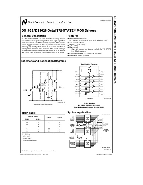
TL F 5875DS1628 DS3628 Octal TRI-STATE MOS DriversFebruary1986DS1628 DS3628Octal TRI-STATE MOS DriversGeneral DescriptionThe DS1628 DS3628are octal Schottky memory driverswith TRI-STATE outputs designed to drive high capacitiveloads associated with MOS memory systems The drivers’output(V OH)is specified at3 4V to provide additional noiseimmunity required by MOS inputs A PNP input structure isemployed to minimize input currents The circuit employsSchottky-clamped transistors for high speed A NOR gate oftwo inputs DIS1and DIS2 controls the TRI-STATE modeFeaturesY High speed capabilitiesTypical5ns driving50pF 8ns driving500pFY TRI-STATE outputsY High V OH(3 4V min)Y High densityEight drivers and two disable controls for TRI-STATEin a20-pin packageY PNP inputs reduce DC loading on bus linesY Glitch-free power up downSchematic and Connection DiagramsTL F 5875–1(Equivalent Input Output Circuit)Truth TableDisable InputInput OutputDIS1DIS2H H X ZH X X ZX H X ZL L H LL L L HH e high levelL e low levelX e don’t careZ e high impedance(off)Dual-In-Line PackageTL F 5875–2Top ViewOrder NumberDS1628J DS3628J DS3628NSee NS Package Number J20A or N20ATypical ApplicationTL F 5875–3 TRI-STATE is a registered trademark of National Semiconductor CorpC1995National Semiconductor Corporation RRD-B30M115 Printed in U S AAbsolute Maximum Ratings(Note1)If Military Aerospace specified devices are required please contact the National Semiconductor Sales Office Distributors for availability and specifications Supply Voltage7 0V Logical‘‘1’’Input Voltage7 0V Logical‘‘0’’Input Voltage b1 5V Storage Temperature Range b65 C to a150 C Maximum Power Dissipation at25 CCavity Package1667mW Molded Package1832mW Lead Temperature(Soldering 10seconds)300 C Derate cavity package11 1mW C above25 C derate molded package 14 7mW C above25 C Operating ConditionsMin Max Units Supply voltage(V CC)4 55 5V Temperature(T A)DS1628b55a125 C DS36280a70 CElectrical Characteristics(Notes2 3)Symbol Parameter Conditions Min Typ Max UnitsV IN(1)Logical‘‘1’’Input Voltage2 0V V IN(0)Logical‘‘0’’Input Voltage0 8V I IN(1)Logical‘‘1’’Input Current V CC e5 5V V IN e5 5V0 140m A I IN(0)Logical‘‘0’’Input Current V CC e5 5V V IN e5 5V b180b400m A V CLAMP Input Clamp Voltage V CC e4 5V I IN e b18mA b0 7b1 2V V OH Logical‘‘1’’Output Voltage V CC e4 5V I OH e b10m A DS16283 44 3V (No Load)DS36283 54 3V V OL Logical‘‘0’’Output Voltage V CC e4 5V I OL e10m A DS16280 250 4V (No Load)DS36280 250 35V V OH Logical‘‘1’’Output Voltage V CC e4 5V I OH e b1 0mA DS16282 53 9V (With Load)DS36282 73 9V V OL Logical‘‘0’’Output Voltage V CC e4 5V I OL e20mA DS1628 DS36280 350 5V(With Load)I ID Logical‘‘1’’Drive Current V CC e4 5V V OUT e0V (Note6)b150mA I OD Logical‘‘0’’Drive Current V CC e4 5V V OUT e4 5V (Note6)150mA Hi-Z TRI-STATE Output Current V OUT e0 4V to2 4V DIS1or DIS2e2 0V b400 140m AI CC Power Supply Current V CC e5 5V One DIS Input e3 0V90120mAAll Other Inputs e X Outputs at Hi-ZDIS1 DIS2e0V Others e3V70100mAOutputs onAll Inputs e0V Outputs Off2550mA Switching Characteristics(V CC e5V T A e25 C)(Note6)Symbol Parameter Conditions Min Typ Max Unitst S ab Storage Delay Negative Edge(Figure1)C L e50pF4 05 0nsC L e500pF6 58 0t S ba Storage Delay Positive Edge(Figure1)C L e50pF4 25 0nsC L e500pF6 58 0t F Fall Time(Figure1)C L e50pF4 26 0nsC L e500pF1922t R Rise Time(Figure1)C L e50pF5 27 0nsC L e500pF2024t ZL Delay from Disable Input to Logical‘‘0’’C L e50pF R L e2k X to V CC1925ns Level(from High Impedance State)to GND(Figure2)t ZH Delay from Disable Input to Logical‘‘1’’C L e50pF R L e2k X to GND1320ns Level(from High Impedance State)to GND(Figure2)2Switching Characteristics(Continued)(V CC e 5V T A e 25 C)(Note 6)Symbol ParameterConditionsMinTyp Max Units t LZ Delay from Disable Input to High Impedance C L e 50pF R L e 400X to V CC 1825ns State (from Logical ‘‘0’’Level)to GND (Figure 3)t HZDelay from Disable Input to High Impedance C L e 50pF R L e 400X to GND 8 515nsState (from Logical ‘‘1’’Level)to GND(Figure 3)AC Test Circuits and Switching Time Waveformst S ab t S ba t r t fTL F 5875–4TL F 5875–5FIGURE 1t ZHTL F 5875–6t ZLTL F 5875–7TL F 5875–8ANY ONE OF EIGHT OUTPUTSFIGURE 2t HZTL F 5875–9t LZTL F 5875–10TL F 5875–11FIGURE 3Note 1 ‘‘Absolute Maximum Ratings’’are those values beyond which the safety of the device cannot be guaranteed Except for ‘‘Operating Temperature Range’’they are not meant to imply that the devices should be operated at these limits The table of ‘‘Electrical Characteristics’’provides conditions for actual device operationNote 2 Unless otherwise specified min max limits apply across the b 55 C to a 125 C temperature range for the DS1628and across the 0 C to a 70 C range for the DS3628 All typical values are for T A e 25 C and V CC e 5VNote 3 All currents into device pins shown as positive all currents out of device pins shown as negative all voltages references to ground unless otherwise noted All values shown as max or min on absolute value basisNote 4 The pulse generator has the following characteristics Z OUT e 50X and PRR s 1mHz Rise and fall times between 10%and 90%points s 5ns Note 5 C L includes probe and jig capacitanceNote 6 When measuring output drive current and switching response for the DS1628and DS3628a 15X resistor should be placed in series with each output3D S 1628 D S 3628O c t a l T R I -S T A TE M O S D r i v e r sPhysical Dimensions inches (millimeters)Ceramic Dual-In-Line Package (J)Order Number DS1628J or DS3628JNS Package Number J20AMolded Dual-In-Line Package (N)Order Number DS3628N NS Package Number N20ALIFE SUPPORT POLICYNATIONAL’S PRODUCTS ARE NOT AUTHORIZED FOR USE AS CRITICAL COMPONENTS IN LIFE SUPPORT DEVICES OR SYSTEMS WITHOUT THE EXPRESS WRITTEN APPROVAL OF THE PRESIDENT OF NATIONAL SEMICONDUCTOR CORPORATION As used herein 1 Life support devices or systems are devices or 2 A critical component is any component of a life systems which (a)are intended for surgical implant support device or system whose failure to perform can into the body or (b)support or sustain life and whose be reasonably expected to cause the failure of the life failure to perform when properly used in accordance support device or system or to affect its safety or with instructions for use provided in the labeling can effectivenessbe reasonably expected to result in a significant injury to the userNational Semiconductor National Semiconductor National Semiconductor National Semiconductor CorporationEuropeHong Kong LtdJapan Ltd1111West Bardin RoadFax (a 49)0-180-530858613th Floor Straight Block Tel 81-043-299-2309。
CTA4-计数器
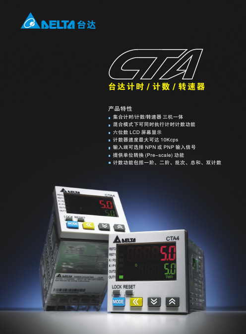
35% to 85% RH (无结露) 等级2
*本型录内容若有变更,恕不另行通知
选购信息
4000A
12 34 5
: 台达计时/计数/转速器 A系列
1 面板尺寸
4:48mmX48mm
2 第二组输出 0:晶体输出;1:继电器输出
3 预设值组数 0:两段设定
4 通讯
含电压晶体输入(PNP):高位准为直流4.5伏特到 30伏特。低位准: 0 到 2伏特
继电器:单刀单闸,最大负载为交流250伏特; 5安培电阻性负载
晶体输出:NPN 开集极(open collector), 30伏特/100毫安时,导通残余电压小於1.5伏特
继电器:单刀双闸,最大负载为交流250伏特, 5安培电阻性负载
输入信号
输出一
输出二
介电强度 耐震动 耐冲击
操作温度 储存温度 操作高度 操作湿度 污染等级
说明 交流电100~240V, 50/60Hz
85%~110% 额定电压 少于10VA
直流12伏特 ±10%;100 毫安 双排六位数LCD显示
非电压晶体输入(NPN):导通阻抗最大1千欧姆, 导通残余电压小于2 伏特
+0.5
44.8mm 0
4
4
.
8
mmຫໍສະໝຸດ +0.5 0(1.76in)
+0.01 0
44.75mm (1.76in)
48.0mm (1.89in)
48.0mm (1.89in)
5.8mm (0.23in)
80.0mm (3.15in)
产品电气规格
项目 电源输入 输入电压范围 消耗功率 提供外部电源 显示方式
