CTDO3316P-222HC中文资料
MC34167MC33167中文资料

MC34167 MC331671简介该MC34167, MC33167系列单片电源开关可用于dc–to–dc优化调节器申请.这些器件的固定频率,电压模式稳压器包含了所有的积极作用需要直接和实施step–down以最小的转换数量voltage–inverting外部元件.它们也可以用于成本效益在step–up转换器应用.潜在市场包括汽车,计算机,工业和成本敏感的消费产品.每一个设备的部分介绍给下面与代表框图所示图13.2振荡器振荡器频率内部编程72 kHz的电容CT和修剪电流源.该充放电率控制在产生一个95%在开关输出的最大占空比.在CT的放电,振荡器产生内部消隐脉冲持有的反相输入与门高,禁用输出开关晶体管.标称振荡器峰值和山谷门槛4.1 V和2.3 V分别.3脉宽调制器脉宽调制器由一个比较器振荡器斜坡电压施加到非反相输入端,而误差放大器的输出应用到反相输入.输出开关导通时启动CT检查排放到振荡器峰谷电压.至于收费的CT电压超过误差放大器的输出,锁存复位,终止输出晶体管的导通时间振荡器的ramp–up时期.这PWM /锁存结合防止在给定的多输出脉冲振荡器时钟周期.数字6和14说明开关输出电压与占空比的补偿.4电流检测该系列采用MC34167当前cycle–by–cycle限制,作为保护手段输出开关晶体管从过度紧张.在每个周期视为一个单独的情况.电流限制是通过监测输出开关晶体管的电流传导期间建设,并经检测过流情况,请立即关闭为振荡器的ramp–up期内开关.集电极电流转换为电压由内部微调电阻和对一个参考比较由电流检测比较器.当电流限制达到阈值,比较器重置PWM 锁存.限流门限点往往设在6.5 A.图9说明开关与输出电流限制门槛温度.5误差放大器和参考一个误差放大器的高增益提供了访问反相输入和输出.该放大器具有典型dc电压增益80 dB,和单位增益带宽600 kHz与相边缘 70度(图3).同相输入偏置内部5.05 V参考并且不固定了.参考具有精度±2.0%在室温下.以提供负载5.0 V中,参考编程50以上mV 5.0 V补偿在电缆的电压降和1.0%从连接器转换器输出.如果转换器设计需要一个输出电压高于5.05 V,电阻更大R1必须加入形成一个分压网络的反馈输入中所示数字13和18.了确定输出方程与分压网络的电压为:Vout+5.05R2R1)1外部回路补偿所需的转换器稳定.一个简单的low–pass滤波器是由连接电阻(R2)从稳压输出到反相输入,以及一系列resistor–capacitor (RF, CF)之间Pins 1和5.补偿网络的元件值显示在电路的申请被选定为each在稳定工作条件下进行测试.该step–down转换器(图18)是最容易补偿稳定.该step–up(图20)和voltage–inverting(图22)配置运作,连续导反激式转换器,而且更难以弥补.该最简单的方法来优化网络是补偿观察输出电压的负载响应一步变化,而调整临界阻尼RF和CF.该最终电路应验证以下四个稳定边界条件.这些条件是最小和最大输入电压,最小和最大负载.通过箝位的电压误差放大器的输出(引脚5)不到150 mV,内部电路将放置到一个低功耗待机模式,从而将权力电源电流36µA与12 V电源电压.图10说明了备用电源电流与电源电压.误差放大器的输出有一个100µA电流源pull–up,可用于实现soft–start.图17显示充电电流源通过一个电容CSS系列二极管.该二极管断开从反馈CSS回路电阻时1.0 M操作它上面的收费销5.范围开关输出输出开关晶体管的设计最大的40 V,以最小的峰值集电极电流时5.5 A.配置为step–down或voltage–inverting应用,如在图18和22,电感会把偏置的输出整流开关关闭时.整流器与较高的正向电压降或长期拖延的时间应该打开不能使用.如果发射器被允许去充分负,集电极电流流过,造成额外的装置暖气,降低转换效率.图8显示到箝位的发射器0.5集电极电流V,在一系列的100µA温度过高.阿1N5825或肖特基势垒整流器相当于推荐履行这些要求.欠压分离欠压分离一直比较成立以保证完全集成电路在输出级的功能已启用.内部参考电压比较器的监测使输出阶段VCC超过5.9 V.为了防止不稳定的输出交叉切换的阈值,0.9 V迟滞.6摩托罗拉设备数据模拟ICMC34167 MC33167热保护内部热关断电路,以保护在事件集成电路的最大结温度超过.当被激活时,通常在170°C,是被迫的锁存成'复位'的状态,关闭输出开关.此功能防止灾难性故障提供偶然的设备过热.它的目的不是要作为一个适当的散热片的替代品.该MC34167包含在5–lead TO–220类型包装.该标签包装是很常见的中心引脚(引脚3),通常连接到地.设计考虑不要试图建立一个转换器上wire–wrap或plug–in原型板.特别应注意分开的信号电流和接地接地通路从负载电流路径.所有高电流回路应尽可能短尽可能使用重型铜runs到尽量减少振荡和辐射EMI.为了获得最佳的操作,严密元件布局建议.电容器Cin, CO,和所有的反馈元件应尽可能靠近IC在身体可能.这也是必须的肖特基二极管连接到开关输出是尽可能靠近尽可能IC.图15.低功耗待机电路+100µA错误放大器1图16.过电压关断电路+100µA错误放大器1120补偿5120补偿R15R1I =待机模式VShutdown = VZener + 0.7图17. Soft–Start电路+100µA错误放大器1120补偿D2Vin1.0 MCss5D1R1tSoft–Start≈35,000 Css。
CT综合测试仪-带伏安特性说明及型号

CT综合测试仪-带伏安特性说明书青岛华顺电气设备厂概述青岛华顺电气有限公司成立于1998年,专业从事电力仪器仪表开发生产和销售,公司自主开发的系列便携式CT、PT伏安特性.变比.极性综合测试仪。
(现有产品:单功能伏安特性测试仪;手动伏安特性、变比、极性测试仪;全自动伏安特性、变比、极性测试仪)。
全自动互感器综合测试仪,是专门为试验互感器伏安特性﹑5% 和10%的误差曲线、二次侧回路检查、变比和极性判别而设计,仅需设定最高测试电压、电流和步长,装置将自动升压,自动将伏安特性曲线描绘出来,省去手动调压、人工记录、描曲线等繁琐劳动。
快捷、简单、方便。
若单机不能满足测试要求,可外接升压器进行试验。
是一台性能价格比较高的多功能试验仪器。
其性能独特,该仪器目前在国内处于领先水平。
注意事项1. 为了保护人身及设备安全,使用前请详细阅读使用说明书,并严格按说明书要求规范操作。
2. 为保证仪器工作的可靠性,请勿将仪器左右侧的散热孔堵塞。
3. 不要让任何异物掉入机箱内,以免发生短路。
4. 试验之前请将仪器可靠接地。
5. 做CT变比试验时,请将CT二次绕组的接地线断开。
6. 做PT伏安特性时,请将被测PT的一次绕组的零位端接地。
7. 如主机不能与电脑进行通讯时,请检查你的电脑串口是否设置为COM1口。
8. 主机最多可保存45组数据,掉电后数据不丢失。
本公司保留对此说明书修改的权利。
产品与说明书不符之处,以实际产品为准。
若在使用中存在技术问题,请与公司联系。
目录第一章产品主要特点 (3)第二章主要技术参数 (3)1 装置面板结构说明 (4)第三章单机运行软件操作方法 (4)1 旋转鼠标使用方法 (4)2 主菜单 (4)3 CT伏安特性试验 (5)3.1 CT伏安特性试验的软件界面 (5)3.2 CT伏安特性试验方法…………………………………………5….3.3 使用主机单机试验 (6)3.4 使用外部升压器试验 (6)3.5 测试结果操作说明 (7)3.6 误差曲线 (8)3.7 查阅以前所保存的测试数据 (8)4.0 CT 变比极性试验 (8)4.1 CT 变比极性试验的软件界面…………………………………8…4.2 CT 变比试验接线 (8)4.3 CT变比试验方法 (9)4.4 CT二次侧回路检查 (9)4.5 PT伏安特性试验方法 (9)4.6 PT变比极性试验方法 (10)4.7 交流耐压测试方法 (10)5 PC 机操作软件使用说明………………………………………11…..附录1 故障维护 (12)附录2 如何更换打印纸 (13)附录3 售后服务承诺 (13)第一章:HS-8A+ 全自动互感器特性综合测试仪主要特点1.仅需设定测试电压、电流和步长,装置将自动升压并能自动将伏安特性测试曲线描绘出来,省去手动调压、人工记录、描曲线等烦琐劳动。
LM331中文资料_中文手册_芯片中文资料_芯片中文手册
电压-频率变换器LM331LM331是美国NS公司生产的性能价格比较高的集成芯片。
LM331可用作精密的频率电压(F/V)转换器、A/D转换器、线性频率调制解调、长时间积分器以及其他相关的器件。
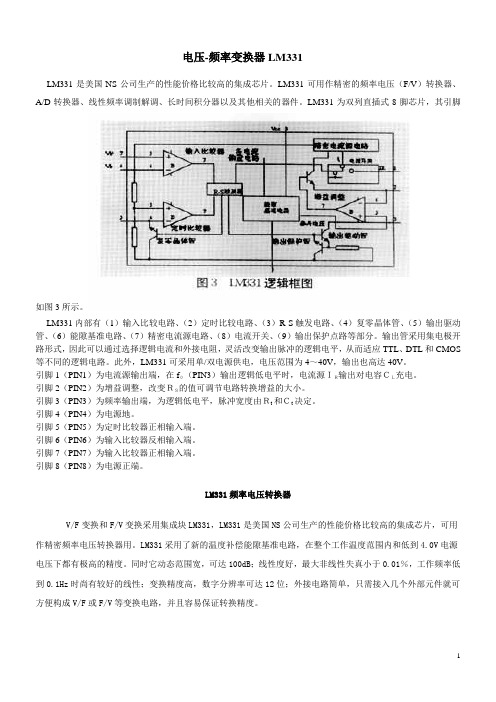
LM331为双列直插式8脚芯片,其引脚如图3所示。
LM331内部有(1)输入比较电路、(2)定时比较电路、(3)R-S触发电路、(4)复零晶体管、(5)输出驱动管、(6)能隙基准电路、(7)精密电流源电路、(8)电流开关、(9)输出保护点路等部分。
输出管采用集电极开路形式,因此可以通过选择逻辑电流和外接电阻,灵活改变输出脉冲的逻辑电平,从而适应TTL、DTL和CMOS 等不同的逻辑电路。
此外,LM331可采用单/双电源供电,电压范围为4~40V,输出也高达40V。
引脚1(PIN1)为电流源输出端,在f0(PIN3)输出逻辑低电平时,电流源IR输出对电容CL充电。
引脚2(PIN2)为增益调整,改变RS的值可调节电路转换增益的大小。
引脚3(PIN3)为频率输出端,为逻辑低电平,脉冲宽度由Rt和Ct决定。
引脚4(PIN4)为电源地。
引脚5(PIN5)为定时比较器正相输入端。
引脚6(PIN6)为输入比较器反相输入端。
引脚7(PIN7)为输入比较器正相输入端。
引脚8(PIN8)为电源正端。
LM331频率电压转换器V/F变换和F/V变换采用集成块LM331,LM331是美国NS公司生产的性能价格比较高的集成芯片,可用作精密频率电压转换器用。
LM331采用了新的温度补偿能隙基准电路,在整个工作温度范围内和低到4.0V电源电压下都有极高的精度。
同时它动态范围宽,可达100dB;线性度好,最大非线性失真小于0.01%,工作频率低到0.1Hz时尚有较好的线性;变换精度高,数字分辨率可达12位;外接电路简单,只需接入几个外部元件就可方便构成V/F或F/V等变换电路,并且容易保证转换精度。
图2是由LM331组成的电压频率变换电路,LM331内部由输入比较器、定时比较器、R-S触发器、输出驱动、复零晶体管、能隙基准电路和电流开关等部分组成。
Fluke3310柔性电流探头详细介绍

工作电压 (见“安全标准”部分)
1000 V 交流有效值或直流
常规特性
探头和电缆材质
Alcryn 2070NC,加强绝缘, UL94 V0,颜色:红色
接合处材质
Lati Latamid 6H-V0 尼龙
探头电缆长度 探头电缆直径
610 mm (24 in.) 3310-PR 1220 mm (48 in.) 33112-PR
®
3310-PR/3312-PR
Flex Current Probe
说明书
简介
Fluke 3310-PR 和 3312-PR 柔性电流探头(以下简称作“探头”) 是采用 Rogowski 原理的交流电流探头。这些探头可配合 Fluke 1750 电力质量记录仪用于在极低频率到 15 kHz 范围之内测 量电流。灵活轻巧的测量头让用户可以快速方便地在不易接近的 区域中进行安装,适合测量粗导线上的电流。 探头针对与 Fluke 1750 电力质量记录仪配套使用而设计。
12.4 mm (0.49 in.)
传感器弯曲半径(最小) 输出电缆 输出接头
38.1 mm (1.5 in.) 双芯屏蔽,3 m 长 LEMO 6 针公头连接器
工作温度范围 存放温度范围 工作湿度
-20 °C 至 +90 °C(-4 °F 至 +194 °F) -40 °C 至 +105 °C(-40 °F 至 221 °F) 15 % 至 85 %(非冷凝)
Fluke 公司保证本产品从购买之日起一年内,其材料和工艺均无任 何缺陷。本项保证不包括保险丝、一次性电池,或者因意外、疏 忽、误用、改装、污染及非正常情况下的操作或处理而造成的损 坏。经销商无权以 Fluke 的名义提供其它任何保证。若要在保修 期内获得保修服务,请与您最近的 Fluke 授权服务中心联系,以 获取有关产品退还的授权信息,并将产品及故障说明寄至该服务 中心。 本项保证是您唯一可以获得的补偿。除此以外,Fluke 不作其它任 何明示或隐含的保证,例如适用于某一特殊目的的隐含保证。 FLUKE 不应对基于任何原因或推测的任何特别、间接、偶发或后 续的损坏或损失负责。由于某些州或国家不允许将隐含保证或偶 发或后续损失排除在外或加以限制,故上述的责任限制或许对您 不适用。
电压互感器测试仪说明书
电压互感器测试仪说明书由于输入输出端子、测试柱等均有可能带电压,在插拔测试线、电源插座时,会产生电火花,小心电击,避免触电危险,注意人身安全!安全要求请阅读下列安全注意事项,以免人身伤害,为了避免可能发生的危险,只可在规定的范围内使用。
只有合格的技术人员才可执行维修。
—防止火灾或人身伤害使用适当的电源线。
只可使用专用并且符合规格的电源线。
正确地连接和断开。
当测试导线与带电端子连接时,请勿随意连接或断开测试导线。
注意所有终端的额定值。
为了防止火灾或电击危险,请注意所有额定值和标记。
在进行连接之前,请阅读使用说明书,以便进一步了解有关额定值的信息。
使用适当的保险丝。
只可使用符合规定类型和额定值的保险丝。
避免接触裸露电路和带电金属。
有电时,请勿触摸裸露的接点和部位。
请勿在潮湿环境下操作。
请勿在易爆环境中操作。
-安全术语警告:警告字句指出可能造成人身伤亡的状况或做法。
目录一、概述 (5)二、主要技术指标 (5)三、使用环境条件 (6)四、测量原理 (6)五、使用方法1、面板配置 (7)2、操作键盘 (7)3、开机 (8)4、仪器复位 (8)5、误差测试 (8)6、电网频率测试 (14)一、概述HGQY-H便携式低校高式电压互感器测试仪是最适合于在现场对电压互感器进行误差测试的全自动智能仪器。
用户不再需要配置笨重的升压器,标准电压互感器,负载箱及调压器(或自动检测台),单台仪器就能对10kV、10kV/3、35kV、35kV/3、110kV/3、220kV/3的电压互感器进行快速测量。
全过程(包括额定、下限的所有测量点)的测试时间不超过1分钟(不含接线时间),其准确度达到0.05级。
本仪器采用320×240点阵的大屏幕液晶显示器,各点的误差可以在同一屏上显示,所有操作均可点击屏幕菜单轻松完成。
本仪器可以存贮200组数据,备有专用接口与PC机通讯。
本仪器约重15kg。
二、主要技术指标●测试范围:10kV、10kV/3、35kV、35kV/3、110kV/3、220kV/3●二次负荷:2.5VA~600VA cosФ=0.8●测量精度:0.05级●测频率:准确度为0.01Hz●仪器设有实时时钟,可实时记录测试时间。
塑壳断路器1

10KA
D3 C45N
结论: 级联技术可以使得分断能力大大低于其安 装处预期短路电流的断路器可以在正常分断的条 件下运行.
施耐德电器公司-ABT产品培训教材-ZXF
23
E37960
Compact NS
有选择性的级联
Compact NS 的配合
无选择性的级联
I B
I A 5 0 k A
A
BP B
P A
Compact 系列产品
一般特性
KA
160
150
150
150
140
120
100
80
70
70
70
70
70
60
50
45
40 36
25
20
0
NS80
NS100 NS160/250 NS400/630 NS800/1250
施耐德电器公司-ABT产品培训教材-ZXF
E37951
=N =H =L
9
Compact NS
15 5/1 15 5/1 15 5/1 15 5/1 15 5/1155/1 15 5/1155/11 55/1155/1155/11 55/1 15 5/1155/1 15 5/1 25 0/2 2
15 5/1 15 5/1 15 5/1 15 5/1 15 5/1155/1 15 5/1155/11 55/1155/1155/11 55/1 15 5/1155/1 25 0/20/2 2
在承受门限电流的电动力之后:能量选择性
17
Compact NS
选择性
新系列
产品:
工具:
1 个标准的脱扣器
1 个简单的原则。
PECcatalog(CCC中文)

熔断时间 最小 100 小时 0.75 秒 0.15秒 0.04 秒 0.02 秒 最大 ---1800 秒 5 秒 0.5 秒 0.2 秒
* 根据使用状况,保险丝特性可能改变.
额定电压 : 直流32V 电池间接耐久性 (周围温度 : 24℃)
在70%额定电流下循环了250000次满足性能要求。每个循环包括10秒开、10秒关的间断电流。
熔断时间 最小 100 小时 60 秒 2 秒 0.2 秒 0.04 秒 最大 ---1800 秒 60 秒 7 秒 1 秒
安培比率% 110% 135% 200% 350% 600%
* 根据使用状况,保险丝特性可能改变.
额定电压 : 直流32V 电池间接耐久性 (周围温度 : 24℃)
在50%额定电流下循环了10000次满足性能要求。每个循环包括5分钟开、10分钟关的间断电流。
在50%额定电流下循环了10000次满足性能要求。每个循环包括5分钟开、10分钟关的间断电流。
% 温度引起的容量变化
容量以 -0.14%/℃的比例变化
汽车零部件 汽车零部件
保险丝 延时保险丝 L型
12.0mm 8.0mm
熔断特性
41.0mm
延时保险丝目录
零部件 编号 3130 3140 3150 3160 3170 3180 3100 3110 3120 安培 比率(A) 30 40 50 60 70 80 100 125 150 外壳 颜色 橙 绿 红 黄 棕 白 蓝 粉红 灰
延时保险丝目录
零部件编号 3420 3430 3440 安培 比率(A) 20 30 40 外壳 颜色 浅蓝 粉红 绿
限时特性
(周围温度 : 24℃)
安培比率 % 110% 200% 350% 600%
331P说明书
打电话 .................................................................................................................................................... 2.2 免提拨号 ................................................................................................................................................ 2.2 电话簿拨号 ........................................................................................................................................... 2.2
ii
目录
Rhine_UK.book Page iii Wednesday, August 28, 2002 1:57 PM
2 ᐺ ; ᒙਜ਼আ፝
功能 ........................................................................................................................................................ 1.2 熟悉您的新机器 ................................................................................................................................... 1.3
MC3317中文资料

Industrial Temperature Range (– 25°C to +85°C) LM201A 0.075 2.0 10 10 50 1.0 0.5 General Purpose N/626, D/751
Internally Compensated
Commercial Temperature Range (0°C to +70°C) LF351 LF411C MC1436, C MC1741C MC1776C MC3476 MC34001 MC34001B MC34071 MC34071A MC34080B MC34081B MC34181 TL071AC TL071C TL081AC TL081C 200 pA 200 pA 0.04 0.5 0.003 0.05 200 pA 200 pA 0.5 500 nA 200 pA 200 pA 0.1 nA 200 pA 200 pA 200 pA 400 pA 10 2.0 10 6.0 6.0 6.0 10 5.0 5.0 3.0 1.0 1.0 2.0 6.0 10 6.0 15 10 10 12 15 15 15 10 10 10 10 10 10 10 10 10 10 10 100 pA 100 pA 10 200 3.0 25 100 pA 100 pA 75 50 100 pA 100 pA 0.05 50 pA 50 pA 100 pA 200 pA 25 25 70 20 100 50 25 50 25 50 25 25 25 50 25 50 25 4.0 8.0 1.0 1.0 1.0 1.0 4.0 4.0 4.5 4.5 16 8.0 4.0 4.0 4.0 4.0 4.0 13 25 2.0 0.5 0.2 0.2 13 13 10 10 55 30 10 13 13 13 13 ±5.0 +5.0 ±15 ±3.0 ±1.2 ±1.5 ±5.0 ±5.0 +3.0 +3.0 ±5.0 ±5.0 ±2.5 ±5.0 ±5.0 ±5.0 ±5.0 ±18 ±22 ±34 ±18 ±18 ±18 ±18 ±18 +44 +44 ±22 ±22 ±18 ±18 ±18 ±18 ±18 JFET Input JFET Input, Low Offset, Low Drift High Voltage General Purpose µPower, Programmable Low Cost, µPower, Programmable JFET Input JFET Input High Performance Single Supply Decompensated High Speed, JFET Input Low Power, JFET Input Low Noise, JFET Input Low Noise, JFET Input JFET Input JFET Input N/626, D/751 N/626, D/751 P1/626, D/751 P1/626, D/751 P1/626, D/751 P1/626 P/626, D/751 P/626, D/751 P/626, D/751 P/626, D/751 P/626, D/751 P/626, D/751 P/626 P/626 D/751 P/626 D/751
CJK22-11P按钮开关

不带灯 双位钮
●黑 (K)
CJK22-□B/G1R0 ●红 CJK22-□B/W1K0 (R0)
带灯双
位钮 (灯珠
CJK22-□BD/G1R0*
为黄色 CJK22-□BD/W1K0*
或白色)
●绿 (G1)
●黑 (K0)
○白 (W1)
品名
品名规格
颜 手柄位置
色
二
CJK22-□X2A/
档
■
●
红
右
旋
CJK22-□X2B/
2 动合(2NO)+1 动断(1NC)=3 CJK22-21X3A/■ CJK22-21X3AD/■* CJK22-21CX3A/■ CJK22-21RX3A/■ CJK22-21Y3A/K CJK22-21Xf3A/■ CJK22-21Xf3AD/■* CJK22-21CXf3A/■ CJK22-21RXf3A/■ CJK22-21Yf3A/K
电气寿命
按 钮 /带 灯 按 钮 : ........50×104 次 选 择 开 关 : ............20×104 次
40%负 荷 率
选 择 开 关 : .........20×104 次
四、结构特点
●模块化设计 ,由 操作 部件 、固 定支 架、 触头 模块 、 降压 模块 (灯 钮) 、 LED 灯珠 组成 ; ●各部件采用国际通行的无紧固件自锁联接,拆装方便、可由用户自行选配部件组装。
模块 数量
模块尾部 接线标识
模块侧面 接线示意 图
13、 14
B
1
23、 24
11、 12
A
1
13、 14
60 B
33、 34 1
MC33161DR2G资料

MC34161, MC33161,NCV33161Universal Voltage MonitorsThe MC34161/MC33161 are universal voltage monitors intended for use in a wide variety of voltage sensing applications. These devices offer the circuit designer an economical solution for positive and negative voltage detection. The circuit consists of two comparator channels each with hysteresis, a unique Mode Select Input for channel programming, a pinned out 2.54 V reference, and two open collector outputs capable of sinking in excess of 10mA. Each comparator channel can be configured as either inverting or noninverting by the Mode Select Input. This allows over, under, and window detection of positive and negative voltages. The minimum supply voltage needed for these devices to be fully functional is 2.0 V for positive voltage sensing and 4.0V for negative voltage sensing.Applications include direct monitoring of positive and negative voltages used in appliance, automotive, consumer, and industrial equipment.Features•Unique Mode Select Input Allows Channel Programming •Over, Under, and Window V oltage Detection •Positive and Negative V oltage Detection•Fully Functional at 2.0 V for Positive V oltage Sensing and 4.0 V for Negative V oltage Sensing•Pinned Out 2.54 V Reference with Current Limit Protection •Low Standby Current•Open Collector Outputs for Enhanced Device Flexibility•NCV Prefix for Automotive and Other Applications Requiring Site and Control Changes•Pb−Free Packages are AvailableFigure 1. Simplified Block Diagram(Positive Voltage Window Detector Application)See detailed ordering and shipping information in the package dimensions section on page 15 of this data sheet.ORDERING INFORMATIONMAXIMUM RATINGS (Note 1)Rating Symbol Value Unit Power Supply Input Voltage V CC40V Comparator Input Voltage Range V in−1.0to+40V Comparator Output Sink Current (Pins 5 and 6) (Note 2)I Sink20mA Comparator Output Voltage V out40V Power Dissipation and Thermal Characteristics (Note 2)P Suffix, Plastic Package, Case 626Maximum Power Dissipation @ T A = 70°C Thermal Resistance, Junction−to−AirD Suffix, Plastic Package, Case 751Maximum Power Dissipation @ T A = 70°C Thermal Resistance, Junction−to−AirDM Suffix, Plastic Package, Case 846A Thermal Resistance, Junction−to−AmbientP DR q JAP DR q JAR q JA800100450178240mW°C/WmW°C/W°C/WOperating Junction Temperature T J+150°COperating Ambient Temperature (Note 3) MC34161MC33161NCV33161T A0to+70−40to+105−40 to +125°CStorage Temperature Range T stg−55to+150°C Stresses exceeding Maximum Ratings may damage the device. Maximum Ratings are stress ratings only. Functional operation above the Recommended Operating Conditions is not implied. Extended exposure to stresses above the Recommended Operating Conditions may affect device reliability.1.This device series contains ESD protection and exceeds the following tests:Human Body Model 2000 V per MIL−STD−883, Method 3015.Machine Model Method 200 V.2.Maximum package power dissipation must be observed.3.T low=0°C for MC34161T high =+70°C for MC34161−40°C for MC33161+105°C for MC33161−40°C for NCV33161+125°C for NCV33161ELECTRICAL CHARACTERISTICS (V CC = 5.0 V, for typical values T A = 25°C, for min/max values T A is the operating ambient temperature range that applies [Notes 4 and 5], unless otherwise noted.)Characteristics Symbol Min Typ Max Unit COMPARATOR INPUTSThreshold Voltage, V in Increasing(T A = 25°C)(T A = T min to T max)V th 1.2451.2351.27−1.2951.295VThreshold Voltage Variation (V CC = 2.0 V to 40 V)D V th−7.015mV Threshold Hysteresis, V in Decreasing V H152535mV Threshold Difference |V th1 − V th2|V D− 1.015mV Reference to Threshold Difference (V ref − V in1), (V ref − V in2)V RTD 1.20 1.27 1.32VInput Bias Current(V in = 1.0 V)(V in = 1.5 V)I IB−−4085200400nAMODE SELECT INPUTMode Select Threshold Voltage (Figure 6)Channel 1Channel 2V th(CH1)V th(CH2)V ref+0.150.3V ref+0.230.63V ref+0.300.9VCOMPARATOR OUTPUTSOutput Sink Saturation Voltage (I Sink = 2.0 mA)(I Sink = 10 mA)(I Sink = 0.25 mA, V CC = 1.0 V)V OL−−−0.050.220.020.30.60.2VOff−State Leakage Current (V OH = 40 V)I OH−0 1.0m A REFERENCE OUTPUTOutput Voltage (I O = 0 mA, T A = 25°C)V ref 2.48 2.54 2.60V Load Regulation (I O = 0 mA to 2.0 mA)Reg load−0.615mV Line Regulation (V CC = 4.0 V to 40 V)Reg line− 5.015mV Total Output Variation over Line, Load, and Temperature D V ref 2.45− 2.60V Short Circuit Current I SC−8.530mA TOTAL DEVICEPower Supply Current (V Mode, V in1, V in2 = GND)(V CC = 5.0 V)(V CC = 40 V)I CC−−450560700900m AOperating Voltage Range (Positive Sensing)(Negative Sensing)V CC 2.04.0−−4040V4.Low duty cycle pulse techniques are used during test to maintain junction temperature as close to ambient as possible.5.T low=0°C for MC34161T high=+70°C for MC34161−40°C for MC33161+105°C for MC33161−40°C for NCV33161+125°C for NCV33161V o u t , C H A N N E L O U T P U T V O L T A G E (V )V Mode , MODE SELECT INPUT VOLTAGE (V)Figure 2. Comparator Input Threshold VoltageV V in , INPUT VOLTAGE (V)o u t , O U T P U T V O L T A G E (V )Figure 3. Comparator Input Bias Currentversus Input Voltage, O U T P U T P R O P A G A T I O N D E L A Y T I M E (n s )P H L t I , I N P U T B I A S C U R R E N T (n A )I BV in , INPUT VOLTAGE (V)Figure 6. Mode Select ThresholdsFigure 7. Mode Select Input Currentversus Input VoltageV Mode , MODE SELECT INPUT VOLTAGE (V)r e f V , R E F E R E N C E V O L T A G E (V ), R E F E R E N C E V O L T A G E C H A N G E (m V )r e f V V CC , SUPPLY VOLTAGE (V), S U P P L Y C U R R E N T (m A )C C I Figure 12. Supply Current versusSupply Voltage Figure 13. Supply Current versus Output Sink CurrentI out , OUTPUT SINK CURRENT (mA)2.82.42.01.61.20.80.400−2.0−4.0−6.0−8.0−100.80.60.40.2Figure 14. MC34161 Representative Block DiagramV CCV refOutput 1Output 2Mode SelectInput 1Input 2Mode SelectPin 7Input 1Pin 2Output 1Pin 6Input 2Pin 3Output 2Pin 5CommentsGND 01010101Channels 1 & 2: Noninverting V ref 01010110Channel 1: Noninverting Channel 2: Inverting V CC (>2.0V)01100110Channels 1 & 2: InvertingFigure 15. Truth TableFUNCTIONAL DESCRIPTIONIntroductionTo be competitive in today’s electronic equipment market, new circuits must be designed to increase system reliability with minimal incremental cost. The circuit designer can take a significant step toward attaining these goals by implementing economical circuitry that continuously monitors critical circuit voltages and provides a fault signal in the event of an out−of−tolerance condition. The MC34161, MC33161 series are universal voltage monitors intended for use in a wide variety of voltage sensing applications. The main objectives of this series was to configure a device that can be used in as many voltage sensing applications as possible while minimizing cost. The flexibility objective is achieved by the utilization of a unique Mode Select input that is used in conjunction with traditional circuit building blocks. The cost objective is achieved by processing the device on a standard Bipolar Analog flow, and by limiting the package to eight pins. The device consists of two comparator channels each with hysteresis, a mode select input for channel programming, a pinned out reference, and two open collector outputs. Each comparator channel can be configured as either inverting or noninverting by the Mode Select input. This allows a single device to perform over, under,and window detection of positive and negative voltages. A detailed description of each section of the device is given below with the representative block diagram shown in Figure 14.Input ComparatorsThe input comparators of each channel are identical, each having an upper threshold voltage of 1.27 V ±2.0% with 25 mV of hysteresis. The hysteresis is provided to enhance output switching by preventing oscillations as the comparator thresholds are crossed. The comparators have an input bias current of 60 nA at their threshold which approximates a 21.2M W resistor to ground. This high impedance minimizes loading of the external voltage divider for well defined trip points. For all positive voltage sensing applications, both comparator channels are fully functional at a V CC of 2.0 V. In order to provide enhanced device ruggedness for hostile industrial environments, additional circuitry was designed into the inputs to prevent device latchup as well as to suppress electrostatic discharges (ESD).ReferenceThe 2.54 V reference is pinned out to provide a means for the input comparators to sense negative voltages, as well as a means to program the Mode Select input for window detection applications. The reference is capable of sourcing in excess of 2.0 mA output current and has built−in short circuit protection. The output voltage has a guaranteed tolerance of ±2.4% at room temperature.The 2.54 V reference is derived by gaining up the internal 1.27V reference by a factor of two. With a power supply voltage of 4.0 V, the 2.54 V reference is in full regulation, allowing the device to accurately sense negative voltages. Mode Select CircuitThe key feature that allows this device to be flexible is the Mode Select input. This input allows the user to program each of the channels for various types of voltage sensing applications. Figure 15 shows that the Mode Select input has three defined states. These states determine whether Channel 1 and/or Channel 2 operate in the inverting or noninverting mode. The Mode Select thresholds are shown in Figure 6. The input circuitry forms a tristate switch with thresholds at 0.63V and V ref + 0.23 V. The mode select input current is 10 m A when connected to the reference output, and 42 m A when connected to a V CC of 5.0 V, refer to Figure 7. Output StageThe output stage uses a positive feedback base boost circuit for enhanced sink saturation, while maintaining a relatively low device standby current. Figure 11 shows that the sink saturation voltage is about 0.2 V at 8.0 mA over temperature. By combining the low output saturation characteristics with low voltage comparator operation, this device is capable of sensing positive voltages at a V CC of 1.0V. These characteristics are important in undervoltage sensing applications where the output must stay in a low state as V CC approaches ground. Figure 5 shows the Output V oltage versus Supply V oltage in an undervoltage sensing application. Note that as V CC drops below the programmed 4.5 V trip point, the output stays in a well defined active low state until V CC drops below 1.0 V.APPLICATIONSThe following circuit figures illustrate the flexibility of this device. Included are voltage sensing applications for over, under, and window detectors, as well as three unique configurations. Many of the voltage detection circuits are shown with the open collector outputs of each channel connected together driving a light emitting diode (LED). This ‘ORed’ connection is shown for ease of explanation and it is only required for window detection applications.Note that many of the voltage detection circuits are shown with a dashed line output connection. This connection gives the inverse function of the solid line connection. For example, the solid line output connection of Figure 16 has the LED ‘ON’ when input voltage V S is above trip voltage V2, for overvoltage detection. The dashed line output connection has the LED ‘ON’ when V S is below trip voltage V2, for undervoltage detection.The above figure shows the MC34161 configured as a dual positive overvoltage detector. As the input voltage increases from ground, the LED will turn ‘ON’ when V S1 or V S2 exceeds V 2. With the dashed line output connection, the circuit becomes a dual positive undervoltage detector. As the input voltage decreases from the peak towards ground, the LED will turn ‘ON’ when V S1 or V S2 falls below V 1.For known resistor values, the voltage trip points are:For a specific trip voltage, the required resistor ratio is:V 1+(V th *V H )ǒR 2R 1)1ǓV 2+V thǒR 2R 1)1ǓR 2R 1+V 1V th *V H*1R 2R 1+V 2V th*1Figure 16. Dual Positive Overvoltage DetectorInput V SOutput VoltagePins 5, 6V V GNDV GNDThe above figure shows the MC34161 configured as a dual positive undervoltage detector. As the input voltage decreases towards ground, the LED will turn ‘ON’when V S1 or V S2 falls below V 1. With the dashed line output connection, the circuit becomes a dual positive overvoltage detector. As the input voltage increases from ground, the LED will turn ‘ON’ when V S1 or V S2 exceeds V 2.V 1+(V th *V H )ǒR 2R 1)1ǓV 2+V thǒR 2R 1)1ǓR 21+V 1th *V H*1R 21+V 2th*1For known resistor values, the voltage trip points are:For a specific trip voltage, the required resistor ratio is:Figure 17. Dual Positive Undervoltage DetectorInput V SOutput VoltagePins 5, 6V 2V 1GNDV CC GNDThe above figure shows the MC34161 configured as a dual negative overvoltage detector. As the input voltage increases from ground, the LED will turn ‘ON’ when −V S1 or −V S2 exceeds V 2. With the dashed line output connection, the circuit becomes a dual negative undervoltage detector. As the input voltage decreases from the peak towards ground, the LED will turn ‘ON’ when −V S1 or −V S2 falls below V 1.For known resistor values, the voltage trip points are:For a specific trip voltage, the required resistor ratio is:Figure 18. Dual Negative Overvoltage DetectorV 1+R 1R 2(V th *V ref ))V thV 2+R 1R 2(V th *V H *V ref ))V th *V HR 1R 2+V 1*V th V th *V refR 1R 2+V 2*V th )V H V th *V H *V ref−V Input −V SOutput VoltagePins 5, 6GND V 1V 2V CC GNDwhen −V S1 or −V S2 falls below V 1from ground, the LED will turn ‘ON’ when −V S1 or −V S2 exceeds V 2.For known resistor values, the voltage trip points are:Figure 19. Dual Negative Undervoltage DetectorV 1+R 12(V th *V ref ))V thV 2+R 12(V th *V H *V ref ))V th *V H2th ref2th H ref−V Input −V SOutput VoltagePins 5, 6GND V 1V 2V CC GNDThe above figure shows the MC34161 configured as a positive voltage window detector. This is accomplished by connecting channel 1 as an undervoltage detector,and channel 2 as an overvoltage detector. When the input voltage V S falls out of the window established by V 1 and V 4, the LED will turn ‘ON’. As the input voltage falls within the window, V S increasing from ground and exceeding V 2, or V S decreasing from the peak towards ground and falling below V 3, the LED will turn ‘OFF’.With the dashed line output connection, the LED will turn ‘ON’ when the input voltage V S is within the window.For known resistor values, the voltage trip points are:For a specific trip voltage, the required resistor ratio is:V 1+(V th1*V H1)ǒR 3R 1)R 2)1ǓV 3+(V th2*V H2)ǒR 2)R 3R 1)1ǓV 2+V th1ǒR 31)R 2)1ǓV 4+V th2ǒR 2)R 31)1ǓR 2R 1+V 3(V th2*V H2)V 1(V th1*V H1)*1R 3R 1+V 3(V 1*V th1)V H1)V 1(V th2*V H2)R 21+V 4x V th22th1*1R 31+V 4(V 2*V th1)2th2R R R Output Voltage Pins 5, 6GNDCH2CH1V 4V 3V 2V 1V CC GNDInput V SThe above figure shows the MC34161 configured as a negative voltage window detector. When the input voltage −V S falls out of the window established by V 1and V 4, the LED will turn ‘ON’. As the input voltage falls within the window, −V S increasing from ground and exceeding V 2, or −V S decreasing from the peak towards ground and falling below V 3, the LED will turn ‘OFF’. With the dashed line output connection, the LED will turn ‘ON’ when the input voltage −V S is within the window.For known resistor values, the voltage trip points are:For a specific trip voltage, the required resistor ratio is:Figure 21. Negative Voltage Window DetectorV 1+R 1(V th2*V ref )R 2)R 3)V th2V 2+R 1(V th2*V H2*V ref )R 2)R 3)V th2*V H2V 3+(R 1)R 2)(V th1*V ref )R 3)V th1V 4+(R 1)R 2)(V th1*V H1*V ref )R 3)V th1*V H1R 1R 2)R 3+V 1*V th2V th2*V ref R 1R 2)R 3+V 2*V th2)V H2V th2*V H2*V ref R 3R 1)R 2+V th1*V ref V 3*V th1R 3R 1)R 2+V th1*V H1*V ref V 4)V H1*V th1R R R Output Voltage Pins 5, 6GND CH2CH1V V V V V CC GNDInput −V SThe above figure shows the MC34161 configured as a positive and negative overvoltage detector. As the input voltage increases from ground, the LED will turn ‘ON’ when either −V S1 exceeds V 2, or V S2 exceeds V 4. With the dashed line output connection, the circuit becomes a positive and negative undervoltage detector.As the input voltage decreases from the peak towards ground, the LED will turn ‘ON’ when either V S2 falls below V 3, or −V S1 falls below V 1.For known resistor values, the voltage trip points are:For a specific trip voltage, the required resistor ratio is:Figure 22. Positive and Negative Overvoltage DetectorV 1+R 3R 4(V th1*V ref ))V th1V 2+R 3R 4(V th1*V H1*V ref ))V th1*V H1V 3+(V th2*V H2)ǒR 2R 1)1ǓV 4+V th2ǒR 2R 1)1ǓR 3R 4+(V 1*V th1)(V th1*V ref )R 3R 4+(V 2*V th1)V H1)(V th1*V H1*V ref )R 2R 1+V 4V th2*1R 2R 1+V 3V th2*V H2*1−V S1V S2Output Voltage Pins 5, 6GND V CC GNDInput −V S1V 4V 3V 1V 2Input V S2The above figure shows the MC34161 configured as a positive and negative undervoltage detector. As the input voltage decreases toward ground, the LED will turn ‘ON’ when either V S1 falls below V 1, or −V S2 falls below V 3. With the dashed line output connection, the circuit becomes a positive and negative overvoltage detector. As the input voltage increases from the ground, the LED will turn ‘ON’ when either V S1 exceeds V 2, or −V S1 exceeds V 1.For known resistor values, the voltage trip points are:For a specific trip voltage, the required resistor ratio is:Figure 23. Positive and Negative Undervoltage DetectorV 1+(V th1*V H1)ǒR 4R 3)1ǓV 2+V th1ǒR 43)1ǓV 3+R 1R 2(V th *V ref ))V th2V 4+R 1R 2(V th *V H2*V ref ))V th2*V H2R 4R 3+V 2V th1*1R 4R 3+V 1V th1*V H1*1R 1R 2+V 4)V H2*V th2V th2*V H2*V ref R 1R 2+V 3*V th2V th2*V refV 2V 1V 3V 4GND V CC GNDOutputVoltagePins 5, 6Input −V S2Input V S1The above figure shows the MC34161 configured as an overvoltage detector with an audio alarm. Channel 1 monitors input voltage V S while channel 2 is connected as a simple RC oscillator. As the input voltage increases from ground, the output of channel 1 allows the oscillator to turn ‘ON’ when V S exceeds V 2.For known resistor values, the voltage trip points are:For a specific trip voltage, the required resistor ratio is:Figure 24. Overvoltage Detector with Audio AlarmV 1+(V th *V H )ǒR 2R 1)1ǓV 2+V th ǒR2R 1)1ǓR 2R 1+V 1V th *V H*1R 2R 1+V 2V th*1R R V 2V 1Input V SOutput Voltage Pins 5, 6GNDV CC GNDThe above figure shows the MC34161 configured as a microprocessor reset with a time delay. Channel 2 monitors input voltage V S while channel 1 performs the time delay function. As the input voltage decreases towards ground, the output of channel 2 quickly discharges C DLY when V S falls below V 1. As the input voltage increases from ground, the output of channel 2 allows R DLY to charge C DLY when V S exceeds V 2.For known resistor values, the voltage trip points are:For a specific trip voltage, the required resistor ratio is:Figure 25. Microprocessor Reset with Time DelayV 1+(V th *V H )ǒR 2R 1)1ǓV 2+V thǒR 2R 1)1ǓFor known R DLY C DLY values, the reset time delay is:R 2R 1+V 1V th *V H*1R 2R 1+V 2V th*1R DLYR R Input V SOutput Voltage Pin 6V 2V 1GNDV CC GNDV CC GNDOutput Voltage Pin 511 −V th V CCt DLY = R DLY C DLY InB+ Array RTNThe above circuit shows the MC34161 configured as an automatic line voltage selector. The IC controls the triac, enabling the circuit to function as a fullwave voltage doubler or a fullwave bridge. Channel 1 senses the negative half cycles of the AC line voltage. If the line voltage is less than150V, the circuit will switch from bridge mode to voltage doubling mode after a preset time delay. The delay is controlled by the 100 k W resistorand the 10 m F capacitor. If the line voltage is greater than 150V, the circuit will immediately return to fullwave bridge mode.Figure 26. Automatic AC Line Voltage SelectorFigure 27. Step−Down ConverterV in 12VOTestConditionsResults Line Regulation V in = 9.5 V to 24 V, I O = 250 mA 40 mV = ±0.1%Load Regulation V in = 12 V, I O = 0.25 mA to 250 mA 2.0 mV = ±0.2%Output Ripple V in = 12 V, I O = 250 mA 50 mVpp EfficiencyV in = 12 V, I O = 250 mA87.8%The above figure shows the MC34161 configured as a step−down converter. Channel 1 monitors the output voltage while Channel 2 performs the oscillator function. Upon initial powerup, the converters output voltage will be below nominal, and the output of Channel 1 will allow the oscillator to run. The external switch transistor will eventually pump−up the output capacitor until its voltage exceeds the input threshold of Channel 1. The output of Channel 1 will then switch low and disable the oscillator. The oscillator will commence operation when the output voltage falls below the lower threshold of Channel 1.ORDERING INFORMATIONDevice Package Shipping†MC34161D SOIC−898 Units/RailMC34161DG SOIC−8(Pb−Free)MC34161DR2SOIC−82500/T ape & ReelMC34161DR2G SOIC−8(Pb−Free)MC34161DMR2Micro84000/T ape & ReelMC34161DMR2G Micro8(Pb−Free)MC34161P PDIP−850 Units/RailMC34161PG PDIP−8(Pb−Free)MC33161D SOIC−898 Units/RailMC33161DG SOIC−8(Pb−Free)MC33161DR2SOIC−82500/T ape & ReelMC33161DR2G SOIC−8(Pb−Free)MC33161DMR2Micro84000/T ape & ReelMC33161DMR2G Micro8(Pb−Free)MC33161P PDIP−850 Units/RailMC33161PG PDIP−8(Pb−Free)NCV33161DR2*SOIC−82500/T ape & Reel†For information on tape and reel specifications, including part orientation and tape sizes, please refer to our Tape and Reel Packaging Specifications Brochure, BRD8011/D.*NCV: T low = −40°C, T high = +125°C. Guaranteed by design. NCV prefix is for automotive and other applications requiring site and control changes.PACKAGE DIMENSIONSNOTES:1.DIMENSION L TO CENTER OF LEAD WHEN FORMED PARALLEL.2.PACKAGE CONTOUR OPTIONAL (ROUND OR SQUARE CORNERS).3.DIMENSIONING AND TOLERANCING PER ANSI Y14.5M, 1982.DIM MIN MAX MIN MAX INCHESMILLIMETERS A 9.4010.160.3700.400B 6.10 6.600.2400.260C 3.94 4.450.1550.175D 0.380.510.0150.020F 1.02 1.780.0400.070G 2.54 BSC 0.100 BSC H 0.76 1.270.0300.050J 0.200.300.0080.012K 2.92 3.430.1150.135L 7.62 BSC 0.300 BSC M −−−10 −−−10 N0.76 1.010.0300.040__PDIP−8CASE 626−05ISSUE LPACKAGE DIMENSIONSSOIC−8 NBCASE 751−07ISSUE AHNOTES:1.DIMENSIONING AND TOLERANCING PERANSI Y14.5M, 1982.2.CONTROLLING DIMENSION: MILLIMETER.3.DIMENSION A AND B DO NOT INCLUDEMOLD PROTRUSION.4.MAXIMUM MOLD PROTRUSION 0.15 (0.006)PER SIDE.5.DIMENSION D DOES NOT INCLUDE DAMBARPROTRUSION. ALLOWABLE DAMBARPROTRUSION SHALL BE 0.127 (0.005) TOTALIN EXCESS OF THE D DIMENSION ATMAXIMUM MATERIAL CONDITION.6.751−01 THRU 751−06 ARE OBSOLETE. NEWSTANDARD IS 751−07.DIMAMIN MAX MIN MAXINCHES4.805.000.1890.197MILLIMETERSB 3.80 4.000.1500.157C 1.35 1.750.0530.069D0.330.510.0130.020G 1.27 BSC0.050 BSCH0.100.250.0040.010J0.190.250.0070.010K0.40 1.270.0160.050M0 8 0 8N0.250.500.0100.020S 5.80 6.200.2280.244 YM0.25 (0.010)Z S X S____ǒmminchesǓSCALE 6:1*For additional information on our Pb−Free strategy and solderingdetails, please download the ON Semiconductor Soldering andMounting Techniques Reference Manual, SOLDERRM/D.SOLDERING FOOTPRINT*PACKAGE DIMENSIONSMicro8t CASE 846A−02ISSUE GNOTES:1.DIMENSIONING AND TOLERANCING PER ANSI Y14.5M, 1982.2.CONTROLLING DIMENSION: MILLIMETER.3.DIMENSION A DOES NOT INCLUDE MOLD FLASH, PROTRUSIONS OR GATE BURRS. MOLD FLASH, PROTRUSIONS OR GATE BURRS SHALL NOT EXCEED 0.15 (0.006) PER SIDE.4.DIMENSION B DOES NOT INCLUDE INTERLEAD FLASH OR PROTRUSION.INTERLEAD FLASH OR PROTRUSION SHALL NOT EXCEED 0.25 (0.010) PER SIDE.5.846A−01 OBSOLETE, NEW STANDARD 846A−02.*For additional information on our Pb−Free strategy and solderingdetails, please download the ON Semiconductor Soldering and Mounting Techniques Reference Manual, SOLDERRM/D.SOLDERING FOOTPRINT*8XDIM A MIN NOM MAX MIN MILLIMETERS−−−− 1.10−−INCHES A10.050.080.150.002b 0.250.330.400.010c 0.130.180.230.005D 2.90 3.00 3.100.114E 2.903.00 3.100.114e 0.65 BSCL 0.400.550.700.016−−0.0430.0030.0060.0130.0160.0070.0090.1180.1220.1180.1220.026 BSC 0.0210.028NOM MAX 4.75 4.90 5.050.1870.1930.199H EON Semiconductor and are registered trademarks of Semiconductor Components Industries, LLC (SCILLC). SCILLC reserves the right to make changes without further notice to any products herein. SCILLC makes no warranty, representation or guarantee regarding the suitability of its products for any particular purpose, nor does SCILLC assume any liability arising out of the application or use of any product or circuit, and specifically disclaims any and all liability, including without limitation special, consequential or incidental damages.“Typical” parameters which may be provided in SCILLC data sheets and/or specifications can and do vary in different applications and actual performance may vary over time. All operating parameters, including “Typicals” must be validated for each customer application by customer’s technical experts. SCILLC does not convey any license under its patent rights nor the rights of others. SCILLC products are not designed, intended, or authorized for use as components in systems intended for surgical implant into the body, or other applications intended to support or sustain life, or for any other application in which the failure of the SCILLC product could create a situation where personal injury or death may occur. Should Buyer purchase or use SCILLC products for any such unintended or unauthorized application, Buyer shall indemnify and hold SCILLC and its officers, employees, subsidiaries, affiliates,and distributors harmless against all claims, costs, damages, and expenses, and reasonable attorney fees arising out of, directly or indirectly, any claim of personal injury or death associated with such unintended or unauthorized use, even if such claim alleges that SCILLC was negligent regarding the design or manufacture of the part. SCILLC is an Equal Opportunity/Affirmative Action Employer. This literature is subject to all applicable copyright laws and is not for resale in any manner.PUBLICATION ORDERING INFORMATIONMicro8 is a trademark of International Rectifier.。
ACPL-331J CN的中文资料

ACPL-331J 1.5A电流输出的IGBT门极驱动光耦集成的(Vce)饱和度检测,欠压锁定,故障状态反馈和有源米勒钳位综述:ACPL - 331J是一种先进的1.5 A的输出电流,方便易用的智能化的门极驱动器使得IGBT的Vce的故障保护更加紧凑,价格合理,且易于实现功能,如集成的Vce检测,欠压锁定(UVLO),IGBT的“软”关断,隔离的集电极开路故障反馈和有源米勒钳位提供最大的设计灵活性和保护电路。
ACPL - 331J包含了一个GaAsP的LED。
通过该LED完成光电信号的耦合。
ACPL-331J非常适合用于驱动电机控制领域的功率IGBT和MOSFET。
这些光耦的电压、电流供给使其非常适用用于直接驱动1200V 100A以下的IGBT。
对于更高功率等级的IGBT,ACPL-331J通常被用来驱动由分离器件构成的IGBT门极驱动器。
ACPL-331J具备一个峰值为891V的绝缘电压。
结构框图:产品特点:z滞后的欠压封锁功能z饱和度侦测z米勒钳位z隔离的开路集电极故障反馈z IGBT软关断z IGBT下个开通周期的故障复位z提供SO - 16封装z安规认证详细说明:z 1.5A的最大输出峰值电流z 1.0A的最小输出峰值电流z温度范围内最大250nS的传输延时z100nS最大脉冲宽度失真z在V CM = 1500 V时,最小15 kV/µs的共模抑制能力z最大供电电流I CC(max) < 5 mAz温度范围内工作电压可达15V-30Vz1A的米勒钳位。
该脚不用时必须同VEE短接z宽的工作温度范围:–40°C to 100°C应用:z IGBT和功率MOSFET的驱动z交流和直流无刷电机驱动z变频器和UPS引脚功能介绍订货信息ACPL-331J 经过3750 Vrms 1分钟测试,符合UL1577标准。
备注 表面 符合IEC / EN产品编号 符合ROHS 标准 封装方式 安装 卷带装 DIN EN 60747-5-2 数量-000E SO-16 X X 45/管ACPL-331J -500E X X X 850/卷 订购时,从产品编号列表中选择产品编号,并结合其他所需的选项形成定单输入。
全自动互感器综合测试仪说明书

概述武汉世纪华胜科技有限公司专业从事电力仪器仪表开发生产和销售,公司自主开发的 RX系列便携式CT、 PT 伏安特征 . 变比 . 极性综合测试仪。
(现有产品:单功能伏安特征测试仪;手动伏安特征、变比、极性测试仪;全自动伏安特征、变比、极性测试仪)。
全自动互感器综合测试仪,是特意为试验互感器伏安特征﹑ 5% 和 10%的偏差曲线、二次侧回路检查、变比和极性鉴别而设计,仅需设定最高测试电压、电流和步长,装置将自动升压,自动将伏安特征曲线描述出来,省去手动调压、人工记录、描曲线等繁琐劳动。
快捷、简单、方便。
若单机不可以知足测试要求,可外接升压器进行试验。
是一台性能价钱比较高的多功能试验仪器。
其性能独到,该仪器目前在国内处于当先水平。
公司拥有标准厂房,一批专业技术人员从事电力仪表的销售及售后服务、技术支持工作,优良的产质量量及完美的售后服务在用户中有着优秀的口碑。
公司产品用户波及电业局、电厂、电力工程公司、煤炭公司、钢铁公司等领域。
日行风格:全心全意。
日行精神:写我们所做的,做我们所写的。
日行目标:把小产品做大,把大产品做成大家的产品。
注意事项1.为了保护人身及设施安全,使用前请详尽阅读使用说明书,并严格按说明书要求规范操作。
2.为保证仪器工作的靠谱性,请勿将仪器左右边的散热孔拥塞。
3.不要让任何异物掉入机箱内,免得发生短路。
4.试验从前请将仪器靠谱接地。
5.做 CT变比试验时,请将 CT 二次绕组的接地线断开。
6.做 PT 伏安特征时,请将被测 PT 的一次绕组的零位端接地。
7. 如主机不可以与电脑进行通信时,请检查你的电脑串口能否设置为COM1口。
8.主机最多可保存 45 组数据,掉电后数据不丢掉。
本公司保存对此说明书改正的权益。
产品与说明书不符之处,以实质产品为准。
若在使用中存在技术问题,请与公司联系。
目录第一章品主要特色..⋯⋯⋯⋯⋯⋯⋯⋯⋯⋯⋯⋯⋯⋯.. ⋯⋯ . ⋯⋯. ⋯⋯⋯⋯ .第二章主要技参数⋯⋯⋯⋯⋯⋯⋯⋯⋯⋯⋯⋯⋯⋯⋯⋯⋯⋯⋯⋯1装置面板构明⋯⋯⋯⋯⋯⋯⋯⋯⋯⋯⋯⋯⋯⋯⋯⋯⋯⋯第三章机运转件操作方法⋯⋯⋯⋯⋯⋯⋯⋯⋯⋯⋯⋯⋯⋯⋯⋯⋯1旋鼠使用方法⋯⋯⋯⋯⋯⋯⋯⋯⋯⋯⋯⋯⋯⋯⋯⋯⋯⋯2主菜⋯⋯⋯⋯⋯⋯⋯⋯⋯⋯⋯⋯⋯⋯⋯⋯⋯⋯⋯⋯⋯⋯⋯3CT 伏安特征⋯⋯⋯⋯⋯⋯⋯⋯⋯⋯⋯⋯⋯⋯⋯⋯⋯⋯⋯⋯CT伏安特征的件界面⋯⋯⋯⋯⋯⋯⋯⋯⋯⋯⋯⋯⋯⋯⋯.CT伏安特征方法⋯⋯⋯⋯⋯⋯⋯⋯⋯⋯⋯⋯⋯⋯⋯⋯⋯⋯.使用主机机⋯⋯⋯⋯⋯⋯⋯⋯⋯⋯⋯⋯⋯⋯⋯⋯⋯....使用外面升器⋯⋯⋯⋯⋯⋯⋯⋯⋯⋯⋯⋯⋯⋯⋯......果操作明⋯⋯⋯⋯⋯⋯⋯⋯⋯⋯⋯⋯⋯⋯⋯⋯.. ⋯差曲⋯⋯⋯⋯⋯⋯⋯⋯⋯⋯⋯⋯⋯⋯⋯⋯⋯⋯⋯从前所保存的数据⋯⋯⋯⋯⋯⋯⋯⋯⋯⋯⋯⋯⋯..CT 比极性⋯⋯⋯⋯⋯⋯⋯⋯⋯⋯⋯⋯⋯⋯⋯⋯⋯⋯⋯CT 比极性的件界面⋯⋯⋯⋯⋯⋯⋯⋯⋯⋯⋯⋯⋯⋯⋯CT 比接⋯⋯⋯⋯⋯⋯⋯⋯⋯⋯⋯⋯⋯⋯⋯⋯⋯⋯⋯⋯CT 比方法⋯⋯⋯⋯⋯⋯⋯⋯⋯⋯⋯⋯⋯⋯⋯⋯⋯⋯⋯CT 二次回路⋯⋯⋯⋯⋯⋯⋯⋯⋯⋯⋯⋯⋯⋯⋯⋯⋯⋯⋯PT 伏安特征方法⋯⋯⋯⋯⋯⋯⋯⋯⋯⋯⋯⋯⋯⋯⋯⋯..PT 比极性方法⋯⋯⋯⋯⋯⋯⋯⋯⋯⋯⋯⋯⋯⋯⋯..沟通耐方法⋯⋯⋯⋯⋯⋯⋯⋯⋯⋯⋯⋯⋯⋯5 PC机操作件使用明⋯⋯⋯⋯⋯⋯⋯⋯⋯⋯⋯⋯⋯⋯⋯⋯..附 1附 2附 3故障⋯⋯⋯⋯⋯⋯⋯..怎样更打印⋯⋯⋯⋯⋯⋯⋯⋯⋯⋯⋯⋯⋯⋯⋯.. ⋯⋯⋯售后服承⋯⋯⋯⋯⋯⋯⋯⋯⋯⋯⋯⋯⋯⋯⋯⋯⋯⋯⋯⋯⋯第一章: RX842全自动互感器特征综合测试仪主要特色1.仅需设定测试电压、电流和步长,装置将自动升压并能自动将伏安特征测试曲线描述出来,省去手动调压、人工记录、描曲线等烦杂劳动。
WS-222C说明书

WS-222C数字显示双温度控制器说明书一、功能特点1.伟森WS-222C型温控器采用触摸按键,内置电源和继电器,一体化智能控制。
2.具有双温度数字显示,双温度控制,压缩机延时启动保护、探头温度校准、探头故障自诊断等功能。
3.适用于直冷双压缩机1匹以下机型。
二、主要技术参数1.电源电压:110~240VAC2.温度探头::NTC,2条,2米长3.温度显示范围:-45~66℃,精度±1℃4.控温温度范围:-45~45℃,出厂值:0℃5.继电器触点容量:压缩机:30A/240VAC6.外观尺寸:142×41×68 mm(长×宽×深),安装开孔尺寸:137×32 mm(长×宽)7.工作环境温度:-10~60℃;8.参数表:1.制冷指示灯:压缩机工作,制冷灯亮;压缩机延时启动,制冷灯闪烁;压缩机停止,制冷灯熄。
四、设置操作(注:按键时松开手时间小于1秒为“连续按键”)1.开机/关机操作:长按住键3秒钟以上可分别选择冷藏和冷冻的开机/关机。
显示“- - -”为关机状态。
2.设置控制温度:(1)长按住键3秒钟,显示冷藏控制温度,松开手后,闪烁显示冷藏控制温度。
(2)按住按或键可改变冷藏控制温度。
(3)不按键3秒钟后,接着闪烁显示冷冻控制温度。
(4)按住按或键可改变冷冻控制温度。
(5)不按键3秒钟后,返回显示探头温度。
3.查看和设置参数(密码“53”):连续按键5次、再连续按键3次,可进入自动依序显示参数代码和参数值状态:●按或键可修改对应参数代码的参数值。
●不按键,3秒后显示下一组参数代码和参数值。
●显示到最后参数代码和参数值,不按键,3秒后退出。
4.恢复参数出厂值(密码“55”):连续按键5次、再连续按键5次,所有参数恢复成出厂值,显示闪烁一下返回。
五、控制原理1.恒温控制:当探头温度≥设定控制温度+回差温度,而且通电后压缩机的停机时间大于延时启动时间时,压缩机启动制冷;当探头温度≤设定的控制温度,压缩机就停止制冷。
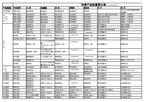
华普产品配置简介表070110
DAV-M2
DAV-M20 DAV-M25 DAV MM25EDV01 M300DV10 M3DV02 M3700DV01 M300DV10 M829DV10 MD0802ADV01 M829DV10 M829DV10 M829DV12 M829DV13 M827DV12 1613C Rev1.2 M827DV12 亿博达MT1389DE M856DV01
R838SV10 R808SV01 R808SV01 R808SV01 8393C Rer1.4 R808SV01
R801SV01 R801SV02 R801SV02 R801SV01 R801SV02 R838SV10 R838SV10 R838SV10 R808SV01 R801SV01 R550SV50 KD0823BSV01 10005C 10005C R858DV10 R858DV10 R808SV01 FK0861BSV03 R838SV10
话简板 K315SV10 K180SV03 K1803S02 K1806S05 K1809S01
输出板 R-OUT5 R838SV10 R1803S02 R1803S03 R1809D03 R100DV12 R200DV12 R838SV10 R1SV01(M1) P3SV01 R1SV01(M1)
芯 片
适配器 适配器 10004C Ver2.4 10004C Ver2.4 变压器EI57/35
K816SV03 K203SV02
AML3418或AML3400+VT7208 AML3433+VT7208 AML3438+VT7208 AML3438+VT7208 MT1389XE/D MT1389DE/E MT1389D/MAG+MT1336/B MT1389QE/D MT1389QE/D MT1389DE/H MT1389QE/D
CTU样本

CTU空气断路器和负荷开关产品目录施耐德电气善用其效尽享其能全球能效管理专家施耐德电气为世界100多个国家提供整体解决方案,其中在能源与基础设施、工业过程控制、楼宇自动化和数据中心与网络等市场处于世界领先地位,在住宅应用领域也拥有强大的市场能力。
致力于为客户提供安全、可靠、高效的能源,施耐德电气2011年的销售额为224亿欧元,拥有超过130,000名员工。
施耐德电气助您——善用其效,尽享其能!施耐德电气在中国1987年,施耐德电气在天津成立第一家合资工厂梅兰日兰,将断路器技术带到中国,取代传统保险丝,使得中国用户用电安全性大为增强,并为断路器标准的建立作出了卓越的贡献。
90年代初,施耐德电气旗下品牌奇胜率先将开关面板带入中国,结束了中国使用灯绳开关的时代。
施耐德电气的高额投资有力地支持了中国的经济建设,并为中国客户提供了先进的产品支持和完善的技术服务,中低压电器、变频器、接触器等工业产品大量运用在中国国内的经济建设中,促进了中国工业化的进程。
目前,施耐德电气在中国共建立了53个办事处,28家工厂,7个物流中心,1个研修学院,3个研发中心,1个实验室,700多家分销商和遍布全国的销售网络。
施耐德电气中国目前员工数近28,000人。
通过与合作伙伴以及大量经销商的合作,施耐德电气为中国创造了成千上万个就业机会。
施耐德电气能效管理平台凭借其对五大市场的深刻了解、对集团客户的悉心关爱,以及在能效管理领域的丰富经验,施耐德电气从一个优秀的产品和设备供应商逐步成长为整体解决方案提供商。
今年,施耐德电气首次集成其在建筑楼宇、IT、安防、电力及工业过程和设备等五大领域的专业技术和经验,将其高质量的产品和解决方案融合在一个统一的架构下,通过标准的界面为各行业客户提供一个开放、透明、节能、高效的能效管理平台,为企业客户节省高达30%的投资成本和运营成本。
转变p为了更好的改变带给电力生活前所未有的高效无忧目录概述 (6)功能和特性 (12)推荐安装方式 (35)尺寸和连接 (46)电路图 (61)附加特性 (66)选型指南 (68)相关产品简介 (81)随着我国供电系统的发展,从住宅小区配电间、箱式变电站,到输变电站和城农网改造,现代配电网络正发生着变化:供电网络规模不断扩大;配电系统保护日益复杂;供电可靠性、连续性要求不断提高;电力管理难度更大;用户的需求不断从电力供给转向电力服务……CTU系列低压断路器,为输配电系统量身定做,全面满足上述供电系统需求:●秉承施耐德电气一贯出色品质,经典的高可靠、免维护、高环境适应性设计!●零飞弧、完善锁定、双重绝缘、人性化操作,提供最高等级的安全!●经典的保护功能和基础的测量功能,实现最简约的选择!CTU系列低压断路器基于供配电客户需求进行全新设计,引领先进供电系统应用理念:●两进线一母联自动投切系统,实现低压系统智能切换!●独特合环控制功能,避免线路切换产生停电或晃电!●全新环保设计,贯穿产品寿命每一阶段!转变,为更可靠、更高效、更智能的配电网络应用而改变,我们为现在和将来而设想:现代供配电网络——能否通过优化电网管理,使系统运行维护更加便捷、高效;能否通过完备应用,带给用户更多价值、服务!高标准的环境适应性CTU系列低压断路器所具备的高环境适应能力,可以保障配电系统在剧烈环Array境变化或严酷环境条件下依然稳定运行,例如建筑领域常用的箱式变电站,无空调环境的地下配电室,或空间狭小的安装环境。
橙光电Eaton PDF33F0250P3DN产品说明书

Eaton PDF33F0250P3DNPower Defense Globally Rated 100% UL, Frame 3, Three Pole, 250A, 25kA/480V, PXR25 LSIG w/ Modbus RTU, CAM Link and Relays, No TerminalsEaton Power Defense molded case circuit breakerPDF33F0250P3DN 786679573624109.1 mm 257.1 mm 138.9 mm 5.92 kg Eaton Selling Policy 25-000, one (1) year from the date of installation of theProduct or eighteen (18) months from thedate of shipment of the Product,whichever occurs first.RoHS Compliant IEC 60947-2CCC MarkedProduct NameCatalog Number UPCProduct Length/Depth Product Height Product Width Product Weight WarrantyCompliancesCertifications250 AComplete breaker 3Three-polePD3 Global (100% UL)Class A PXR 25 LSIGModbus RTU and CAM Link600 Vac600 VNo Terminals25 kAIC at 480 Vac 18 kAIC Icu/ 5 kAIC Ics/ 37.8 kAIC Icm @525V South Africa (IEC)10 kAIC Icu @250 Vdc25 kAIC Icu/ 20 kAIC Ics/ 52.5 kAIC Icm @440V (IEC) 25 kAIC Icu/ 25 kAIC Ics/ 52.5 kAIC Icm @380-415V (IEC) 20 kAIC Icu/ 20 kAIC Ics/ 42 kAIC Icm @480V Brazil (IEC) 25 kAIC @480V (UL) 14 kAIC @600V (UL/CSA) 35 kAIC @240V (UL)35 kAIC Icu/ 35 kAIC Ics/ 73.5 kAIC Icm @240V (IEC)Eaton Power Defense MCCB PDF33F0250P3DN 3D drawing Power Xpert Protection Manager x64Amperage Rating Circuit breaker frame type Frame Number of poles Circuit breaker type Class Trip Type CommunicationVoltage rating Voltage rating - max Terminals Interrupt rating Interrupt rating range3D CAD drawing packageApplication notesConsulting application guide - molded case circuit breakersBrochuresStrandAble terminals product aidPower Defense brochurePower Defense molded case circuit breaker selection posterPower Defense technical selling bookletCatalogsMolded case circuit breakers catalogPower Xpert Release trip units for Power Defense molded case circuit breakersCertification reportsPDG3 UL authorization 250-600a TMTUPower Defense Declaration concerning California’s Proposition 65PDG3 UL authorization 100-400aInstallation instructionsPower Defense Frame 3 Breaker Instructions (IL012107EN).pdfMultimediaPower Defense Frame 3 Variable Depth Rotary Handle Mechanism Installation How-To VideoEaton Power Defense for superior arc flash safetyPower Defense BreakersPower Defense molded case circuit breakersPower Defense Frame 2 Variable Depth Rotary Handle Mechanism Installation How-To VideoPower Defense Frame 6 Trip Unit How-To VideoPower Defense Frame 5 Trip Unit How-To VideoSpecifications and datasheetsEaton Specification Sheet - PDF33F0250P3DNTime/current curvesPower Defense time current curve Frame 3 - PD3White papersIntelligent power starts with accurate, actionable dataMolded case and low-voltage power circuit breaker healthMaking a better machineIntelligent circuit protection yields space savingsImplementation of arc flash mitigating solutions at industrial manufacturing facilitiesSafer by design: arc energy reduction techniquesMolded case and low-voltage breaker healthEaton Corporation plc Eaton House30 Pembroke Road Dublin 4, Ireland © 2023 Eaton. All Rights Reserved. Eaton is a registered trademark.All other trademarks areproperty of their respectiveowners./socialmedia。
