联物CO2-T-S中文版(终稿)
CO2 (VC1008T)说明书

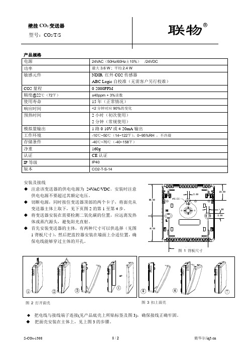
要特点● 采用瑞典森尔公司一流的红外波导专利技术及镀金空气采样探头,确保测量数据的准确性● 两路模拟信号输出和一路继电输出● 简单和低成本的设计,是连接到 DDC/PLC控制的最佳选择● 非特殊的应用环境,无需校准● 两种防护等级不同的壳体1) IP20 壁挂式 VC1008T2) IP65 管道式 VC1008T-Ks技术指标工作温度:0~50℃储存温度:-40~70℃工作湿度:0~95% (无结露)预热时间:≤ 1 分钟(在全规格时,≤ 15 分钟)预期传感器寿命:> 15 年供电电源:24VAC/DC功耗:< 1W测量方法:红外波导技术及镀金采样探头,自然气体扩散原理,具备ABC自动校准功能测量范围:0~2000ppm CO2 (其他量程,-0.6%/2%/4%可选)重复率:± 20ppm + 读数的 ±1%精度:± 30ppm + 读数的 ±2%年度漂移:< ±10ppm (ABC 自动校准功能启动)压力误差:读数的 1.6% 每 kPa输出1:0~10V,0~2000ppm CO2输出2:4~20mA,0~2000ppm CO2输出3:设定点 1000ppm,N.C. & N.O.继电器输出(输出3可选输出点)选型表型号产品描述壁挂式二氧化碳变送器,量程范围VC1008T2000PPM管道式二氧化碳变送器,量程范围VC1008T-Ks2000PPM可选-R 继电器输出-NTC NTC温度传感器-PTXX PT100或PT1000温度传感器其它量程0.6%/2%/4%外型尺寸壁挂式壳体(标准型号)外型尺寸:100 x 80 x 27 mm(长x宽x高)孔间距: 60 mm 符合 J-boxes 欧洲标准管道式壳体(型号-Ks)外型尺寸:142 x 84 x 46 mm(长x宽x高)管道探头长度:245 mm(可以调整长度)。
死亡应对量表的汉化及信效度检验

[10(Curley M#Hasbani N R,Quigley S M#et al.Predicting pressure injury risk in pediatric patients:the Braden QD Scale[J(J Pediatr,2018,192:189195.'1(刘晶晶•癌症患者照顾者支持性照护需求量表的汉化及照护方案的初步构建[D(.合肥:安徽医科大学#016.'2(曹娜•护士对老年患者疼痛评估测评量表的汉化及评价[D(.郑州:郑州大学#018'3(吴明隆•结构方程模型AMOS的操作与应用[M(重庆:重庆大学出版社,2010:212.'4(闫甜甜.中文版压疮愈合状态评价及分类量表DESIGN-R的信效度研究[D(青岛:青岛大学2015.'5(吴明隆.问卷统计分析实务SPSS操作与应用[M(.重庆:重庆大学出版社,2010:240,251-252.'6(樊华.中文版COMHON压力性损伤评估量表在ICU患者中的应用研究[D(合肥:安徽医科大学2018'7(霍婉君.ICU压疮危险评估量表的构建[D(.广州:广东药科大学2018'8(程莉萍,董建英,雷娜,等.NICU患儿压疮预防护理进展中华现代护理杂志,2014,20(20):2590-2592.'19(TumeL N#SinerS#Sco t E#etal Theprognosticabili-ty of early Braden Q Scores in critica l y i l children'J(NursCritCare201419(2):98-103'0(唐绪容,周蓉,屈虹,等.儿童压力性损伤风险评估量表的比较分析'(护理学杂志,2019,34(18):5861'1(吴玉洁,王建平,吕俊英,等.新生儿压力性损伤风险评估现状及评估量表应用分析'(中国实用护理杂志# 201935(36):2836-2839'2(赵琦,徐雲,蒋红,等•医疗器械相关压力性损伤预防和管理的最佳证据总结'(护理学杂志,2019,34(13):8-11(本文编辑钱媛)死亡应对量表的汉化及信效度检验郑瑞双1,郭巧红",严梅#,赵云4,陈璐5,周志欢6摘要:目的引进并翻译死亡应对量表并在肿瘤科护士中检验其信效度$方法按照Brislin翻译模式对英文版量表进行直译和回译,采用专家咨询及预试验对中文版量表进行初步检验;选取全国5所三级甲等肿瘤专科医院的446名肿瘤科护士进行信效度验证$结果中文版量表包括6个因子共28个条目,S-CVI为0.987!-CVI为0.832〜1000;6个因子累积方差贡献率为60.800%。
BW Clip 二氧化碳、氮、二氧化碳、二氧化砷单气体检测器说明书
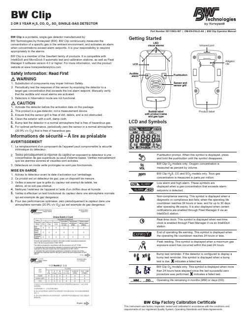
Part Number 50115903-067 | OM-EN-PALO-A 8 | BW Clip Operator ManualBW Clip is a portable, single-gas detector manufactured byBW T echnologies by Honeywell (BW). BW Clip continuously measures theconcentration of a specific gas in the ambient environment, and activates an alarm when concentrations exceed alarm setpoints. It is your responsibility to respond appropriately to the alarms.BW Clip is a member of the GasAlert family of products. It is compatible withIntelliDoX and MicroDock II automatic test and calibration stations, as well as Fleet Manager II software version 4.0 or higher. For more information, visit the product website at Safety Information: Read First 1.Substitution of components may impair Intrinsic Safety.2.Periodically test the response of the sensor by exposing the detector to a target gas concentration that exceeds the low alarm setpoint. Manually verify that the audible and visual alarms are activated.3.Detectors in hibernation mode are not functional.1.Activate the detector before the activation date on the package.2.This product is a gas detector, not a measurement device.3.Ensure that the sensor grill is free of dirt, debris, and is not obstructed.4.Clean the exterior with a soft, damp cloth.5.Bump test the detector in a normal atmosphere that is free of hazardous gas.6.For optimal performance, periodically zero the sensor in a normal atmosphere (20.9% v/v O 2) that is free of hazardous gas.Informations de sécurité – À lire au préalableAVERTISSEMENT1.2. Le remplacement d’un composant de l’appareil peut compromettre la sécuritéintrinsèque du détecteur.T estez périodiquement la réponse du capteur en exposant le détecteur à uneconcentration de gaz supérieure au seuil d’alarme basse. Vérifiez manuellement que les alarmes sonores et visuelles sont activées.3.Détecteurs en mode veille prolongée ne sont pas fonctionnels.MISE EN GARDE1.Activez le détecteur avant la date d’activation sur l’emballage.2.Ce produit est un détecteur de gaz, pas un dispositif de mesure.3.Veillez à assurer que la grille du capteur est exempt de saleté, les débris, et ne soit pas obstrué.toyez l’extérieur de l’appareil à l’aide d’un chiffon doux et humide.5.Veillez à effectuer un test fonctionnel du capteur dans une atmosphère normalequi est exempte de gaz dangereux6.Pour des performances optimales, zéro périodiquement le capteur dans uneatmosphère normale (20,9% v/v O 2) qui est exempte de gaz dangereux.BW Clip Factory Calibration Certi f icateThis instrument was factory inspected, tested and calibrated in accordance with the conditions and requirements of our registered Quality System, Operating Standards and Sales Agreements.Getting Startedwith product name and gas typeLEDLCD and SymbolsBW Clip O 2 models only. Oxygen concentration is measured as percent by volume.BW Clip H 2S, CO and SO 2 models only. T oxic gas concentration is measured in parts per million.Low alarm and high alarm. These symbols are displayed when a gas concentration that exceeds alarm setpoints is detected.Non-compliance warning. This symbol is displayed when a diagnostic or compliance test fails; when the operating life countdown reaches 24 hours or less; and for up to 30 days after operating life expiry. It is also displayed when certain notifications are enabled through Fleet Manager II via an IntelliDoX station.Real-time clock. This symbol is displayed when real-time clock is enabled through Fleet Manager II via an IntelliDoX station.End of operating life warning. This symbol is displayed when the operating life countdown reaches 24 hours or less.Peak reading. This symbol is displayed when a maximum gasexposure event has occurred within the past 24 hours.Operating life remaining in months (MM) or days (DD).a WARNINGa CAUTIONBump test reminder. If the detector is configured to display a bump test reminder, this symbol is displayed when a bump test is due. indicates a failed test.BW Clip O 2 models only. This symbol is displayed when more than 24 hours have elapsed since the last successful zero procedure was performed. indicates a failed test.Activate a New Detector1.Move to a normal atmosphere (20.9% v/v O2) that is free of hazardousgas.2.Press and hold the pushbutton until a 5 second countdown is displayed,and then continue to hold until the countdown is complete.3.When the countdown is complete, the LCD and LEDs turn on and thenturn off. The detector performs an internal diagnostic test.4.When the diagnostic test is successful, the alarm setpoints aredisplayed and the LEDs flash.5.The sensor stabilization countdown is displayed. During the countdown,the detector vibrates continuously for 20 seconds. The time required to stabilize varies depending on sensor type. When the countdownreaches 0, the LEDs flash and the audible alarm beeps.6. When the type of gas detected and the operating life countdown aredisplayed, the detector is in normal operating mode.When the detector is in normal operating mode, the typeof gas detected is permanently displayed. The remainingoperating life is displayed until it is disrupted by apushbutton action, gas alarm, or error event.When the detector is activated for the first time, theoperating life countdown is displayed. The countdowndisplays remaining operating life in months until thecountdown reaches 90 days or less before expiry.When the operating life countdown reaches 90 days orless before expiry, the countdown display changes todays. The countdown displays the remaining operatinglife in days until the countdown reaches 24 hours or lessbefore expiry.When the operating life countdown reaches 24 hours orless before expiry, the countdown display changes tohours, and the EXPIRY! warning and non-compliancesymbol are displayed.When the operating life countdown ends, the detectordeactivates and detector safety functions are disabled. Itis possible to retrieve event logs for a limited time afterexpiry. The EXPIRY! warning and non-compliance symbolare displayed for up to 30 days after expiry.Internal Diagnostic TestsActivated detectors automatically perform one internal diagnostic test every 24 hours. If the internal diagnostic test fails, the diagnostic fail-safe begins. Diagnostic Fail-Safe1.The EXPIRY! warning and non-compliance symbol are displayed.2.The detector beeps and vibrates.3.The LEDs flash 2 times per second for 15 seconds.4.OFF or an error code is displayed. The detector is deactivated.It is possible to retrieve the event logs for a limited time after expiry. If you are unable to retrieve the event logs, contact BW.Alarms and WarningsAn alarm is initiated when the sensor is exposed to a gas concentration that exceeds alarm setpoints. The alarm persists until the alarmgas concentration returns to an acceptable range. You can useFleet Manager II via an IntelliDoX station to enable the display of the gas concentration reading during an alarm. Battery life decreases rapidly when the detector is in alarm condition.Low AlarmAudible: 1 beep per secondVisual: 1 flash per secondVibration: 1 vibration per secondHigh AlarmAudible: 2 beeps per secondVisual: 2 flashes per secondVibration: 2 vibrations per secondOver-Limit and Under-Limit AlarmsIf the gas concentration is beyond the sensor range, OL(over-limit) or -OL (under-limit) is displayed.Audible: 2 beeps per secondVisual: 2 flashes per secondVibration: 2 vibrations per second2ModelsFor O2models only, the Automatic Zero Reminder isdisplayed when more than 24 hours have elapsed sincethe last successful zero procedure was performed. Peak ReadingsThe peak readings symbol is displayed when the sensoris exposed to a gas concentration that exceeds the alarmsetpoints. It is no longer displayed when more than24 hours have passed since the last alarm, or when a successful bump test is performed via an IntelliDoX or MicroDock II station. Non-compliance Symbol and LED Indicators The non-compliance warning symbol is displayed when:•an internal diagnostic test fails;• a bump test or zero procedure fails;• a bump test is due, if enabled;•the sensor is exposed to a gas concentration that exceeds alarm setpoints, if enabled.The non-compliance warning symbol is no longer displayed when more than 24 hours have passed since the last alarm, or when a successful bump test is performed via an IntelliDoX or MicroDock II station. The non-compliance warning symbol is permanently displayed when the service-life countdown reaches 24 hours or less before expiry, and for up to 30 days after expiry.When Non-compliance after gas exposure is enabled throughFleet Manager II via an IntelliDoX station, the LEDs flash in an alternating pattern when the non-compliance warning symbol is displayed. When the symbol is first displayed, the top LEDs flash. After 30 seconds, the side LEDs flash. After 30 seconds, the pattern repeats until the non-compliance warning symbol is no longer displayed.NOTE: When the detector is bump tested via a MicroDock II station, an abnormal test result may occur if non-compliance LEDs are flashing.To suspend the flashing for up to 10 minutes, press and release the pushbutton. When the flashing stops, insert the detector and perform the test. If the bump test fails, the LEDs resume flashing.Recall Events and SettingsWhen the detector is in normal operating mode, press the pushbutton at any time to scroll through events and settings that are not empty or disabled through Fleet Manager II via an IntelliDoX station. Events and settings are displayed in this order:1.Peak Reading , if available, and when a maximum gas exposure event has occurred within the past 24 hours.2.Time of Peak Reading , if Real-time Clock display is enabled.3.Low Alarm Setpoint4.High Alarm Setpoint5.Real-time Clock , if enabled.6.Firmware Version7.Next Bump Due , if enabled.8.Hibernation , for 2-year H 2S and CO hibernation models only.While an event or setting is displayed, press the pushbutton to scroll to the next available event or setting. If you do not press the pushbutton, or if you have reached the last available event or setting, the detector returns to normal operation.Zero the SensorOver time and through use, the sensor baseline at zero exposure may drift from the manufacturer’s baseline. For optimal performance of O 2 models, BW recommends that you zero the O 2 sensor once every 24 hours or when the Automatic Zero Reminder is displayed. For all other models, BW recommends that you zero the sensor periodically.Zero Procedure1.Move to a normal atmosphere (20.9% v/v O 2) that is free of hazardous gas.2.Press and hold the pushbutton until a 5 second countdown is displayed, and then continue to hold until the countdown is complete.3.When the countdown is complete, the Zero procedure begins and ZErO is displayed.4.When Zero is successful, PASS is displayed, and thenthe detector returns to normal operation.5.If Zero is not successful, the non-compliance LED flashes. FAIL and the non-compliance warning symbol are displayed. Press the pushbutton to acknowledge the result and return to normal operation. The non-compliance warning symbol is displayed and the non-compliance LED flashes. Perform the Zero procedure again. If the procedure fails again, contact BW.Bump TestsWhen the detector is configured to display a bump test reminder, the bump test symbol is displayed when a bump test is due. For best results, bump test the detector via an IntelliDoX or MicroDock II station. Bump tests performed via an IntelliDoX or MicroDock II station are logged as bump tests. Manual bump tests are logged as unsafe gas concentrations.Event LogsThe detector stores the last 35 events that occurred, including peak readings, bump tests and auto zeros. Each record contains:•detector serial number, sensor type and life-remaining;•total number of events that have occurred;•event type and duration;•alarm level(s) in ppm or %;•time elapsed since the alarm occurred in days/hours/minutes;•duration of the alarm (minutes/seconds).Use Fleet Manager II via an IntelliDoX or MicroDock II station to transfer event logs from the detector to a computer. When logs are transferred via an IntelliDoX station, the most recent 35 events are transferred. When logs are transferred via a MicroDock II station, the most recent 10 events are transferred.Optional SettingsUse Fleet Manager II via an IntelliDoX station to enable the following optional settings for BW Clip detectors.Display Gas Reading During AlarmWhen Display gas reading during alarm is enabled, the gas concentration is displayed when a gas alarm event is detected. The gas concentration is displayed until the alarm event ends.Non-compliance After Gas ExposureWhen Non-compliance after gas exposure is enabled, the LEDs flash in an alternating pattern when the sensor is exposed to a gas concentration that exceeds alarm setpoints. When the gas exposure is detected, the top LEDs flash. After 30 seconds, the side LEDs flash. After 30 seconds, the pattern repeats until more than 24 hours have passed since the last alarm, or when a successful bump test is performed via an IntelliDoX or MicroDock II station.Real-time Clock DisplayWhen Real-time Clock Display is enabled, you can display the current time by pressing the pushbutton to Recall Events and Settings , and then continuing to press the pushbutton until the time is displayed.Time may be displayed in 12-hour or 24-hour clock format.HibernationHibernation is a factory installed feature that is available for 24-month H 2S and CO detectors. When Hibernation is activated, the operating life countdown is suspended. Use Hibernation to deactivate the detector for 7 days or longer, up to a maximum of 12 months. When Hibernation is activated, all detector safety functions are disabled.Activate Hibernation via BW Clip Hibernation Case1.Have ready a BW Clip Hibernation Case. To purchase a Case, contact BW or an authorized distributor.2.Move to a normal atmosphere (20.9% v/v O 2) that is free of hazardous gas.3.Verify that the detector is in normal operating mode.4.Press the pushbutton to Recall Events and Settings ,and then continue to press the pushbutton until Hib is displayed.5.While Hib is displayed, press the pushbutton until a 5 second countdown is displayed. When the countdown is complete, the 20-second Hibernation counter is displayed.6.While the Hibernation counter is displayed, place the detector into a BW Clip Hibernation Case and then close the case firmly. The detector enters Hibernation mode. All detector safety functions are disabled.7.To reactivate the detector, open the case.Activate Hibernation through Fleet Manager II via IntelliDoXe Fleet Manager II to activate Hibernation on Insertion via an IntelliDoX station, and then insert the detector in the configuredstation. The detector event logs are retrieved, and the detector enters Hibernation mode. All safety functions are disabled, and the detector may be removed from the IntelliDoX station.2.To reactivate the detector, press and hold the pushbutton until a5 second countdown is displayed, and then continue to hold until the LCD and LEDs turn on and off. The detector performs a self-diagnostic test. When the test is successful, the type of gas detected and the remaining operating life are displayed. The detector is in normal operating mode.3.For more information, refer to the operator manuals for the IntelliDoX station and Fleet Manager II software version4.0 or higher.BW Clip2 OR3 YEAR H2S, CO, O2, SO2SINGLE-GAS DETECTORAbout this PublicationThis publication is an operator guide for BW Clip portable single-gas detectors manufactured by BW Technologies by Honeywell. It is intended for use with the following models:• 24- and 36-month H2S and CO Detectors• 24-month O2 detector• 24-month SO2detectorCopyright, Notice, TrademarksWhile this information is presented ingood faith and believed to be accurate,BW Technologies by Honeywell (BW) disclaims the implied warranties of merchantability and fitness for a particular purpose and makes no express warranties except as may be stated in its written agreement with and for its customers.In no event is BW liable to anyone for any indirect, special or consequential damages. The content in this document is subject to change.Contact UsCorporate HeadquartersBW Technologies by HoneywellSuite 110 4411-6 Street SECalgary, AlbertaCanada, T2G 4E8Toll-free: 1-800-663-4164AmericasBW Technologies by Honeywell405 Barclay Blvd.Lincolnshire IL USA 60069Toll-free:1-888-749-8878EuropeBW Technologies by HoneywellHatch Pond House4 Stinsford RoadNuffield Industrial EstatePoole Dorset BH17 0RZ United Kingdom Toll-free: +44(0)1295 700300OtherBW Technologies by HoneywellToll-free: 1-403-248-9226******************** Warranty Registration/support/product-registrationMaximum Operating Life24-month Detector2 years after activation, assuming2 minutes of alarm time per day.Note: 24-month H2S and CO detectorsthat use hibernation may extend theservice period of the detector up to anadditional year. The service life will end once the detector reaches 24 months of actual operation. Hibernation provides a maximum service life of 36 months.36-month Detector3 years after activation, assuming1 minute of alarm time per day. Detection RangeH2S 0 to 100 ppmCO 0 to 300 ppmO20 to 25% by volumeSO20 to 100 ppmFactory Alarm SetpointsLow Alarm High AlarmH2S 10 ppm 15 ppmCO 35 ppm 200 ppmO219.5% vol 23.5% volSO25 ppm 10 ppmUse Fleet Manager II via an IntelliDoXstation to adjust alarm setpoints. Formore information, refer to the operatormanuals for Fleet Manager II softwareversion 4.0 and the IntelliDoX automatictest and calibration station.Ratings and Certi f icationsThe BW Clip is in conformity with thefollowing standards:UL 913 8th EditionULUL 60079-0:2013,UL 60079-11:2013CSA C22.2 No. 157-92:2012,CSA C22.2 No. 60079-0:2011,CSA C22.2 No. 60079-11:2014EN 60079-0:2012 +A11:2013,EN 60079-11:2012IEC 60079-0:2011IEC 60079-11:2011ABNT NBR IEC 60079-0:2008ABNT NBR IEC 60079-11:2009Classified by UL to both US andCanadian Standards as intrinsically safefor Class I, Division 1, Group A, B, C, Dand Class I, Zone 0, Group IIC.ATEXCE 0539 II 1GEx ia IIC T4 Ga IP66/67DEMKO 14 ATEX 1356CEEuropean ConformityE U Declaration of ConformityIECExEx ia IIC T4 Ga IP66/67IECEx UL 14.0063INMETROEx ia IIC T4 GaDNV 15.0024KTL15-KA4BO-03061SpecificationsShelf LifeH2S One (1) year before activationCO One (1) year before activationO2Six (6) months before activationS O2One (1) year before activationInstrument Weightalligator clip included92 grams (3.2 ounces)Instrument Dimensionsalligator clip included41 x 50 x 87 millimeters(1.6 x 2.0 x 3.4 inches)Operating TemperaturesH2S -40° to +50°C (-40° to +122°F)CO -30° to +50°C (-22° to +122°F)O2-20° to +50°C (-4° to +122°F)SO2-30° to +50°C (-22° to +122°F)5% to 95% relative humidity (non-condensing)1/~/media/honeywell-analytics/products/bw-clip/docu-ments/certi icates/korea-certi ication_bw-clip-15ka-4bo0306Visual AlarmFlashing, wide-angled alarm lens with redLEDs plus alarm LCD readoutDisplayLiquid crystal display (LCD)Sensor TypeElectrochemical cellsBatteryLithium, non-replaceableIngress ProtectionIP 66/67Alarm SetpointsInstant low and instant highCalibrationH2S not requiredCO not requiredSO2not requiredO2Perform the Zero procedureonce every 24 hours or when theAutomatic Zero Reminder isdisplayed.Intended UseThis product is classified for use inhazardous atmospheres that are notmore than 21% v/v O2RecyclingThis instrument contains a lithium battery. Donot mix with the solid waste stream. Spentbatteries should be disposed of by a qualifiedrecycler or hazardous materials handler.Products may contain materials that areregulated for transportation under domesticand international dangerous goodsregulations. Return product in compliancewith appropriate dangerous goodsregulations. Contact freight carrier for furtherinstructions.Limited Warranty andLimitation of LiabilityBW Technologies (BW) warrants thisproduct to be free from defects in materialand workmanship under normal use andservice for a period of two or three years(depending upon detector), beginning on thedate of activation. 24-month H2S and COdetectors are covered for up to an additional12 months when hibernation is used, limitedby a total of 24 months of detector operation.This Warranty is valid only if the detector isactivated by the date on the package. Thiswarranty extends only to the sale of new andunused products to the original buyer.BW’s warranty obligation is limited, at BW’soption, to refund of the purchase price, repair,or replacement of a defective product that isreturned to a BW authorized service centerwithin the warranty period. In no event shallBW’s liability hereunder exceed the purchaseprice actually paid by the buyer for theProduct.This warranty does not include:• fuses, disposable batteries or the routinereplacement of parts due to the normalwear and tear of the product arising fromuse;• any product which in BW’s opinion,has been misused, altered, neglectedor damaged by accident or abnormalconditions of operation, handling or use; orThe obligations set forth in this warranty areconditional on:1)proper storage, installation, calibration,use, maintenance and compliance withthe product manual instructions and anyother applicable recommendations of BW;2)the buyer promptly notifying BW of anydefect and, if required, promptly makingthe product available for correction.No goods shall be returned to BWuntil receipt by the buyer of shippinginstructions from BW; and3)the right of BW to require that the buyerprovide proof of purchase such as theoriginal invoice, bill of sale or packing slipto establish that the product is within thewarranty period.THE BUYER AGREES THAT THISWARRANTY IS THE BUYER’S SOLE ANDEXCLUSIVE REMEDY AND IS IN LIEU OFALL OTHER WARRANTIES, EXPRESSOR IMPLIED, INCLUDING BUT NOTLIMITED TO ANY IMPLIED WARRANTY OFMERCHANTABILITY OR FITNESS FOR APARTICULAR PURPOSE. BW SHALL NOTBE LIABLE FOR ANY SPECIAL, INDIRECT,INCIDENTAL OR CONSEQUENTIALDAMAGES OR LOSSES, INCLUDING LOSSOF DATA, WHETHER ARISING FROMBREACH OF WARRANTY OR BASED ONCONTRACT, TORT OR RELIANCE OR ANYOTHER THEORY.Since some countries or states do not allowlimitation of the term of an implied warranty,or exclusion or limitation of incidental orconsequential damages, the limitations andexclusions of this warranty may not apply toevery buyer. If any provision of this warrantyis held invalid or unenforceable by a court ofcompetent jurisdiction, such holding will notaffect the validity or enforceability of any otherprovisions.Audible Alarm≈ 95 dB at 10 cm (3.9 in)Internal Vibrating• any damage or defects attributable torepair of the product by any personother than an authorized dealer, or theinstallation of unapproved parts on theproduct.Internal VibratingOperates to -10°C (+14°F)I ntrinsic Safety Temperature Range-40 °C to +50 °C (-40 °F to +122 °F)UK Office。
VTS CO2 浓度传感器说明书

CO2 TRANSDUCER CO2-SENS-D-MODRTU1.IntroductionThis document describes functionality of CO2 concentration transducer based on integrated MH-Z19B sensor, equipped with RS-485 interface using MODBUS RTU protocol and 0-5V / 0-10V analogue output.NOTES:1) Read this document carefully before attempting to start up the device!2) The device must be installed by qualified staff only.1.1.Functions of the device▪CO2 measurement▪0-5V or 0-10V analogue output (hardware selectable range) proportional to CO2 concentration▪ 3 status LEDs▪RS485 serial interface for remote management (setup and reading of measurement values)◦MODBUS RTU protocol◦integrated terminating resistor 120Ω◦communication in HALF DUPLEX mode◦hardware/software configurable address in the range 1-247◦hardware configurable communication baud rate: 19200, 9600, 4800, 2400◦software configurable communication baud rate: 115200, 57600,38400, 19200, 9600, 4800, 24001.2.Device characteristicsThe main function of the CO2 transmitter is to measure the CO2 concentration in the air using an integrated MH-Z19B sensor. The measurement result, as well as the sensor missing/error status, is processed by the built-in microprocessor and then made available on the RS-485 bus via registers of the MODBUS RTU protocol.Additionally, the measurement result is available as analog signal on the 0-5V / 0-10V voltage output.2.Technical data2.1.General parameters of the transducerPower supply∙DC voltage DC 20-30 V (nom DC 24 V)∙AC voltage AC 20-28 V (nom AC 24 V) Current consumption∙typical30 mA ∙max100 mA LED indicators See section 3.5Signal connection Screw terminals in 5 mm pitch (wire diameter ≤ 2.5 mm)Housing dimensions∙without sampling mast 80x82x55 mm ∙with sampling mast 80x82x280 mm Weight 230g Working environment Dust-free, air, neutral gases Working temperature 0ºC ÷ 50ºC2.2.Parameters of CO2 measurementSensor model MH-Z19B Measurement range 0/400-2000 ppm Measurement accuracy ± (5% of measured value + 50ppm) Sampling period 5 s Response time T90 *) < 2 min *) response time T90 is the time from moment of change of state to the moment when the measurement value reaches 90% of the steady value.2.3.Parameters of analogue outputOutput type voltage Output range 0-5 V or 0-10 V Resolution11.5 bit ∙in [mV] for the range 0-10 V 3.2 mV~ ∙in [mV] for the range 0-5 V 1.6 mV~ Loading capacity RL > 1 kΩRefreshing period 1 s2.4.Parameters of serial interfaceTransmission interface RS-485 Communication protocol MODBUS RTU Transmission type HALF DUPLEX Communication baud rate 2400 / 4800 / 9600 / 19200 / 38400 / 57600 / 115200 Baud/s3.Installation3.1.Safety▪The device must be installed by qualified staff only!▪All connections must be made in accordance with wiring diagrams shown in this document!▪Check all electrical connections prior to commissioning!3.2.Device design3.3. Description of terminalsNotes:1. The RXTX+ and RXTX- signals must be connected to the A and B lines of the MODBUS bus respectively.2. The analogue output returns following voltage values:ION CONCENTRAT RANGEout CO ppmVOLTAGE V 22000⋅=whereas the concentration value can be calculated basing on the voltage value form using the following formula:OUT RANGEION CONCENTRAT V VOLTAGE ppmCO ⋅=20002where:VOLTAGE RANGE = 5V or 10V (0-5V or 0-10V set on the configuration DIP-switch 2 – see section 3.4) Exemplary values are shown in the table below:CO2 concentration [ppm]Voltage range = 5 VVoltage range = 10V0 0.0V 0.0V 400 1.0V 2.0V 1000 2.5V 5.0V 20005.0V10.0VPOWER SUPPLYOR3.4.Configuration of MODBUS bus, serial port and analogue output0 – OFF 1 – ON CONFIGURATION ADDRESSThe purpose of the consecutive switches of the left DIP-switch is as follows (default values are in bold)The device address on the MODBUS bus is set using the right DIP-switch:Note: the configuration set by the means of DIP-switches is read once after device restart (after switching on the power or pressing the RESET button). For this reason, if the DIP-switch settings are changed during operation, then after changing the settings, it is necessary to restart the device by pressing the RESET button or temporarily unplugging the power supply.3.5.LED indicators3.5.1.LED POWER3.5.2.LED LINK3.5.3.LED SENSOR3.6.Recommendations for installationTRANSDUCER (1) TRANSDUCER (2) TRANSDUCER (n)It is recommended that devices on the MODBUS (RS485) are connected in a daisy-chain configuration, whereby 120R terminating resistors should be connected between A and B lines of the bus at both ends of the chain (close to the outer devices). This resistor is built-in in the CO2-SENS-D-MODBRTU transducer and can be switched on using the no. 1 switch on the configuration DIP-switch (see section 3.4).Moreover, shielded cables should be used when the device is operated in high interference environments and the shield should be connected to the nearest PE point on the power supply side.3.7.The automatic zero calibration (ABClogic function)It is assumed that CO2 concentration in the outdoor air amounts to 400 – 500 ppm. The CO2 concentration inside buildings is higher, mainly due to the presence of people. When there are no people in the building and the ventilation systems works properly, the CO2 concentration inside the building decreases to a level close to those of outdoor air.ABClogic is an algorithm for long term tracking of CO2 concentration and adjusting the sensor characteristics in the low concentration range. The sensor stores low values of CO2 concentration from many last days, which enables taking intelligent account of periodical CO2 concentration level increases (e.g. when rooms were used 24 hours per day over a few days). As a result of the ABClogic algorithm, the “automatic zero calibration” of the sensor is carried out.The automatic calibration ABClogic, is designed for applications where rooms remain unoccupied for several hours per day, as a result, CO2 concentration values periodically drop to low values, similar to those outside the building. In contrast, in an environment where the level of CO2 concentration reaches high values and doesn't drop to low values, the ABClogic system should be switched off, because it would adjust automatic calibration to the lowest levels, distorting the values indicated by the sensor.In the sensor described in this document, the ABClogic function is off by default (factory setting). The status of ABClogic function (switching on or off) can be changed by writing the respective command (see section 4.1.1).4.MODBUS protocol4.1.Register mapCommand table:∙Reading registers from addresses not listed in this table results in 0x02 exception.∙Specifying an incorrect or out-of-range parameter value results in entering the value 0xEEEE into the command register.∙The device is configured by writing three registers (password / command / parameter) at the same time using the 0x10 function with the corresponding values – according to the command table, or by writing single registers (using 0x06 or 0x10 function) with the latter writing of a (valid) password causing the execution of thecommand.∙During a single password entry (both with function 0x06 and 0x10) in case of a password match, the correctness of information in command and parameterregisters is checked and if correct, the command is executed.4.1.1.DEV_ID_REG (addr=11=0x000B) – read onlyDEV[4..0] = b11000 –fixed value meaning “air parameter sensors”HV[1..0] – value 0..3 – hardware versionOPTIONS[4..0] – values 0..31 – device typeb10000 – CO2 transducer with MH-Z19B sensorT[1..0] – value 0..3 – type0 – duct type1 – room type2, 3 - reservedCO2 duct sensor in basic hardware version returns the value b1100000100000000=0xC100.4.1.2.SOFT_VER_REG (addr=12=0x000C) – read onlywhereN, A, B are digits in the the 0..9 rangerev (with values 0..9) is a letter in the range ‘a’...’j’.Examples:0x0000 represents software version: 0.00a; 0x4321 → 4.32b ; 0x2345 → 2.34f4.2.Protocol functions4.2.1.Reading the contents of a group of output registers (0x03) Command format:Response format:Error format:4.2.2.Writing single 16-bit registers (0x06)Command format:Response format:Error format:4.2.3.Writing a group of output registers (0x10) Command format:Response format:Error format:4.2.4.Description of errors4.3.Data format4.3.1.Character / byte formatThe following figure shows the format of a byte transmitted in the MODBUS RTU protocol. Each transmitted character has 10 or 11 bits, which are sent in order from the least significant to the most significant.4.3.2. Order of bytes in 16-bit data fields in a transmission frameThe following figure shows the byte order of the 16-bit data fields. For 16-bit data fields, the correct byte order is that the older byte is transmitted first, then the younger byte (HI→LO - BIG ENDIAN), while for the CRC field the younger byte is transmitted first, then the older byte (LO→ HI - LITTLEENDIAN).4.4.CRC check sumWORD CRC16 (const BYTE *nData, WORD wLength){static const WORD wCRCTable[] = {0x0000, 0xC0C1, 0xC181, 0x0140, 0xC301, 0x03C0, 0x0280, 0xC241, 0xC601, 0x06C0, 0x0780, 0xC741, 0x0500, 0xC5C1, 0xC481, 0x0440, 0xCC01, 0x0CC0, 0x0D80, 0xCD41, 0x0F00, 0xCFC1, 0xCE81, 0x0E40, 0x0A00, 0xCAC1, 0xCB81,0x0B40, 0xC901, 0x09C0, 0x0880, 0xC841, 0xD801, 0x18C0, 0x1980, 0xD941, 0x1B00, 0xDBC1, 0xDA81, 0x1A40,0x1E00, 0xDEC1, 0xDF81, 0x1F40, 0xDD01, 0x1DC0, 0x1C80, 0xDC41, 0x1400, 0xD4C1, 0xD581, 0x1540, 0xD701,0x17C0, 0x1680, 0xD641, 0xD201, 0x12C0, 0x1380, 0xD341, 0x1100, 0xD1C1, 0xD081, 0x1040, 0xF001, 0x30C0,0x3180, 0xF141, 0x3300, 0xF3C1, 0xF281, 0x3240, 0x3600, 0xF6C1, 0xF781, 0x3740, 0xF501, 0x35C0, 0x3480, 0xF441, 0x3C00, 0xFCC1, 0xFD81, 0x3D40, 0xFF01, 0x3FC0, 0x3E80, 0xFE41, 0xFA01, 0x3AC0, 0x3B80, 0xFB41, 0x3900, 0xF9C1, 0xF881, 0x3840, 0x2800, 0xE8C1, 0xE981, 0x2940, 0xEB01, 0x2BC0, 0x2A80, 0xEA41, 0xEE01, 0x2EC0, 0x2F80, 0xEF41, 0x2D00, 0xEDC1, 0xEC81, 0x2C40, 0xE401, 0x24C0, 0x2580, 0xE541, 0x2700, 0xE7C1, 0xE681, 0x2640, 0x2200, 0xE2C1, 0xE381, 0x2340, 0xE101, 0x21C0, 0x2080, 0xE041, 0xA001, 0x60C0, 0x6180, 0xA141, 0x6300, 0xA3C1, 0xA281, 0x6240, 0x6600, 0xA6C1, 0xA781, 0x6740, 0xA501, 0x65C0, 0x6480, 0xA441, 0x6C00, 0xACC1, 0xAD81, 0x6D40, 0xAF01,0x6FC0, 0x6E80, 0xAE41, 0xAA01, 0x6AC0, 0x6B80, 0xAB41, 0x6900, 0xA9C1, 0xA881, 0x6840, 0x7800, 0xB8C1,0xB981, 0x7940, 0xBB01, 0x7BC0, 0x7A80, 0xBA41, 0xBE01, 0x7EC0, 0x7F80, 0xBF41, 0x7D00, 0xBDC1, 0xBC81,0x7C40, 0xB401, 0x74C0, 0x7580, 0xB541, 0x7700, 0xB7C1, 0xB681, 0x7640, 0x7200, 0xB2C1, 0xB381, 0x7340, 0xB101, 0x71C0, 0x7080, 0xB041, 0x5000, 0x90C1, 0x9181, 0x5140, 0x9301, 0x53C0, 0x5280, 0x9241, 0x9601, 0x56C0, 0x5780, 0x9741, 0x5500, 0x95C1, 0x9481, 0x5440, 0x9C01, 0x5CC0, 0x5D80, 0x9D41, 0x5F00, 0x9FC1, 0x9E81, 0x5E40, 0x5A00, 0x9AC1, 0x9B81, 0x5B40, 0x9901, 0x59C0, 0x5880, 0x9841, 0x8801, 0x48C0, 0x4980, 0x8941, 0x4B00, 0x8BC1, 0x8A81, 0x4A40, 0x4E00, 0x8EC1, 0x8F81, 0x4F40, 0x8D01, 0x4DC0, 0x4C80, 0x8C41, 0x4400, 0x84C1, 0x8581, 0x4540, 0x8701, 0x47C0, 0x4680, 0x8641, 0x8201, 0x42C0, 0x4380, 0x8341, 0x4100, 0x81C1, 0x8081, 0x4040};BYTE nTemp;WORD wCRCWord = 0xFFFF;while (wLength--){nTemp = *nData++ ^ wCRCWord;wCRCWord >>= 8;wCRCWord ^= wCRCTable[nTemp];}return wCRCWord;}。
基于物联网的CO2排放监测系统方案设计
生产生活息息相关 , 实现经济增 长的同时 , 控制碳排放量 、 实现可 头 的 6位 串 行 数 据 帧 , 以 持续发展 , 是于全球任何一个国家都有需承担的责任和义务 。监 C O : 浓度数据 为例, 其 输 出
测 碳 排 放 是 实 现 经 济 发 展 与 环 境 保 护 之 问 的重 要 实 施 步 骤 , 在 不 格 式 为 ” Z x x x x x Z X X X X X ” , 其
一
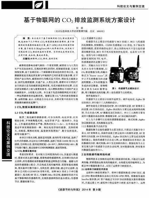
图 1 传 感 器 节 点 模块 设 计
间碳排放 中,占有最大 比例。本文基于先进 的物联 网技术实现 了 路 , 用于数据的无线传输 , 图 1 是传感器节点 的模块 。 种 远程 碳排放 的监测 系统 ,能 够实现 C O 气体 的浓度数 据采 软件流程如下 : 传感器节点主要设计 的软件流程为 :硬件初 始化 、 Z i g B e e 协
感 器的精度 , 需要单独供 电设计 , 防止 因供 电电压不 足引起传 感 器的精度变差 , M C U单 片机 有较宽的供 电范围 ,也采用 3 . 3 V供 电 ,使得 与串 口相接 的传 感 器 有相 同的 T T L电平 。 传 感器提供 的是数 字串行
碳 排 放 是 影 响 全 球 气 候 的一 个 重 要 因数 , 碳 排 放 与 与 人 类 的 接 口 ,其 输 出 为 以 字 符 开
硬件初 始化主要初始化时钟 、 串 口的属性设置 、 R F射频单元 的设置 、 0 s 任 务的设定 。Z i g B e e 协议 执行 主要完成无线 网络 的甄 别、 节点 自动人 网 、 A F数据发送任务执行 。串口工人 例程主要完
数据窜分析 、 A F 协议帧 的构建I 5 } 。 按 照 二 氧化 碳传 感 器原 理 , 可分 为 两 类 : 电 化学 型 、 红 外 成串 口数据 的动态侦测 、 以上几个步骤 可以实现传感器数据 接收 、格式 转换 、 Z i g B e e 吸收分 析 、 半导 体 陶瓷式型 。 电化学 型 产 品一般 体 积小 、 寿命
014-二氧化碳安全技术说明书(MSDS)

不受公安部门管制。
3.0危险性概述
危险性类别:第2.2类不燃气体
入侵途径:吸入、皮肤接触
健康危害:本身无毒。但空气中浓度超过3%时,可能出现呼吸困难、头痛眩晕、呕吐等。10%以上时出现视力障碍、痉挛、呼吸加快、血压升高、意识丧失。25%以上时,出现神经抑制、昏睡、痉挛、窒息至死。接触液体二氧化碳可引起冻伤。
监测方法:气相色谱法
作业现场要求:生产过程密闭,加强通风。
呼吸系统防护:空气浓度超标时,人员撤离现场,紧急事故抢救时须佩戴空气呼吸器或氧气呼吸器。
眼睛防护:带面罩。
手防护:戴防寒手套
其它防护:工作现场禁止烟火,工作前避免饮酒精性饮料。进行就业前和定期体检。
9.0理化特性
参照 “1.0”。
10.0稳定性和反应灵活性
3)工作场所安全使用化学品规定([1996]劳部发423号)等法规;
4)针对化学危险品的安全使用、生产、储存、运输、装卸等方面均作了相应规定;
5)常用危险化学品的分类及标志(GB13690-92)将该物质划为第2.2类 不燃气体;
6)车间空气中二氧化碳卫生标准(GB 16201-1996)规定了车间空气中该物质的最高容许浓度及检测方法。
作业现场注意事项:密封操作,加强通风,操作人员必须经过专门培训,严守操作规程,持证上岗。充装时按充装系数要求控制充装量严禁超装。接触液体二氧化碳要穿戴好护具防止冻伤。
储存注意事项:储存于通风库房,远离火种、热源,保持容器密封,气瓶应有防倒措施,大于10立方米贮槽不能放在室内
8.0接触控制/个体防护
最高允许浓度:中国MAC:18000
包装类别:Ⅲ
包装方法:气瓶,低温容器。
运输注意事项:防止日光暴晒,不能靠近高温火源,气瓶戴瓶帽和防震圈,气瓶搬运过程中不能抛、滑、滚、空运、铁路限量运输。槽车运输槽内压力不能超压。
江西省八校协作体2024-2025学年高二上学期第一次联考生物试题(含答案)

江西省八校协作体高二年级第一次联考生物学考生注意:1.本试卷分选择题和非选择题两部分。
满分100分,考试时间75分钟。
2.答题前,考生务必用直径0.5毫米黑色墨水签字笔将密封线内项目填写清楚。
3.考生作答时,请将答案答在答题卡上。
选择题每小题选出答案后,用2B铅笔把答题卡上对应题目的答案标号涂黑;非选择题请用直径0.5毫米黑色墨水签字笔在答题卡上各题的答题区域内作答,超出答题区域书写的答案无效,在试题卷、草稿纸上作答无效。
4.本卷命题范围:人教版必修1(20%)+必修2(20%)+选择性必修1第1章~第4章第2节(60%)。
一、选择题:本题共12小题,每小题2分,共24分。
每小题只有一个选项符合题目要求。
1.人乳头瘤病毒(HPV)是一类无包膜的双链环状DNA病毒。
当人的皮肤、黏膜发生损伤暴露出基底膜时,HPV的主要衣壳蛋白L1会与基底膜上的受体特异性结合,进而完成吸附、入胞、增殖等过程,造成皮肤和黏膜的多种病变。
下列叙述正确的是()A.HPV需寄生在人的皮肤和黏膜细胞中,因此HPV属于生命系统最基本的结构层次B.可以用富含氨基酸、葡萄糖、无机盐等营养物质的培养基直接培养HPVC.HPV的DNA上无游离的磷酸基团,HPV在增殖的过程中可能会发生基因突变D.HPV的L1与基底膜上的受体特异性结合的过程体现了细胞间的信息交流2.细胞的衰老和死亡与个体的生命历程密切相关。
下列关于细胞生命历程的叙述,错误的是()A.依据端粒学说判断,正常情况下细胞会随着分裂次数的增多而衰老B.正常机体通过细胞凋亡的方式清除被病原体感染的靶细胞C.在一定条件下,细胞会将受损或功能退化的细胞结构等通过溶酶体降解后再利用D.当细胞衰老时,核中的遗传物质会出现收缩状态,胞内所有酶的活性均会降低3.如图是高等植物保卫细胞的局部亚显微结构示意图,①~③表示细胞结构。
已知保卫细胞吸水时,气孔张开;H+-ATPase是一种位于细胞膜上的转运蛋白,同时还具有ATP水解酶活性。
密闭环境中二氧化碳的控制(高清版)
密闭环境中二氧化碳的控制陈根年(中国船舶工业总公司第七一八研究所)目录1. 二氧化碳的危害 (2)2. 清除二氧化碳的基本方法 (3)2.1. 二氧化碳的理化性质 (3)2.1.1. 直接分离法。
(3)2.1.2. 化学吸收法。
(3)2.1.3. 物理吸附法: (4)2.2. 适用于密闭环境的二氧化碳控制方法 (4)2.2.1. 二氧化碳浓度比较低,化学吸收的推动力比较小。
(4)2.2.2. 卫生学要求高。
(4)2.2.3. 密闭空间小,能源有限。
(4)2.2.4. 由于密闭空间内载人有限,后勤保障难, (4)3. 碱金属氢氧化物吸收 (5)3.1. 常见的碱金属碱土金属氧化物和氢氧化物吸收二氧化碳的理论容量见表1。
53.2. 氢氧化锂的性质 (6)3.3. 钠石灰 (6)4. 分子筛系统 (7)5. 一乙醇胺吸收 (9)6. 固态胺吸附 (11)参考文献141.二氧化碳的危害国际标准化组织(ISO)定义,“空气污染:通常系指由于人类活动和自然过程引起某些物质介入大气中,呈现出足够的浓度,达到了足够的时间,并因此而危害了人体的舒适、健康和福利或危害了环境。
”二氧化碳是最常见的气体。
地球大气圈底层的二氧化碳含量约0. 03%。
它主要来自有机物的燃烧和动物的呼吸。
正常人每小时约呼出21L二氧化碳。
在潜艇的密闭舱室内,如不消除二氧化碳,全体艇员呼出的二氧化碳不到5h浓度就积累至1%,15h可以升至3%。
大量的实验说明,人在含3%二氧化碳的空气中暴露数十小时,工作能力、智力活动能力显著下降。
在含 1.5%二氧化碳的空气中暴露几十天,工作能力和基础生理指标无明显变化,慢性呼吸性的酸碱度和电解质平衡出现明显的适应性改变,离开这个环境若干天也未完全恢复。
在含0.5%~0.8%二氧化碳的空气中长期暴露,尚未发现明显的变化。
二氧化碳浓度若升高到5%,同时氧气浓度降低至10.5%,人员在这种环境中暴露几十小时,20%的人主诉头痛、恶心、畏寒、运动功能出现某些障碍。
s型异质结光催化co2
s型异质结光催化co2
S型异质结光催化CO2是一种利用半导体材料制备的光催化剂,用于将二氧化碳(CO2)转化为有用的化学品或燃料。
这种光催化剂的关键部分是S型异质结。
S型异质结由两种不同的半导体材料组成,通常是一种能带结构较窄的半导体和一种能带结构较宽的半导体。
这种结构可以形成电子-空穴对,并且在光照条件下,能够有效地分离和转移这些电荷对。
当S型异质结光催化剂暴露在光线下时,光子会激发半导体材料中的电子,从而产生电子-空穴对。
这些电子-空穴对可以参与CO2分子的还原和氧化反应。
例如,光激发的电子可以被传递给CO2分子,从而减少CO2并产生有机化合物,如甲酸或甲醇。
同时,光激发的空穴可以参与水分子的氧化反应,产生氧气和阳离子。
这种光催化CO2技术具有潜在的环境和能源应用。
通过利用太阳能作为光源,将大量的CO2转化为有用的化学品或燃料,可以减少二氧化碳的排放,并促进可持续发展。
然而,目前仍需要进一步的研究和改进,以提高S型异质结光催化剂的效率和稳定性,以实现其在实际应用中的广泛应用。
1。
THERMO_二氧化碳培养箱中文说明介绍模板之欧阳语创编

THERMO FORMA370/371&380/381高温灭菌,气套CO2培养箱操作手册目录一.参数设置二.参数校准三.系统信息四.报警信息五.高温消毒一、参数设置a 设置温度Thermo Forma 370系列的co2培养箱工作温度范围为10℃–50℃,此温度受环境温度的影响。
出厂时,厂家将温度设定为10℃,在此设置下,所有的加热器都将关闭。
按以下步骤设置温度:1.按“MODE”到“SET”位置。
2.按“←→”直到显示“TEMP XX.X”信息3.按“↑↓”设置所需要的温度值。
4.按“ENTER”保存设定值。
5.按“MODE”到“RUN”位置或按“←→”选择其他的参数。
b.设置过温温度370系列的co2培养箱具有了第二级温度监控系统来监测箱体内的温度。
这是机器的一个自我保护功能。
一旦温度不能控制,机器将关闭所有的加热器。
箱体内的报警温度是过温温度的±1℃。
厂家设定过温温度是40℃,但是过温温度最高可设定为55℃。
若设置温度高于过温温度,机器将给过温温度自动增加1℃。
一般过温温度应高于设置温度1℃。
按以下步骤设置过温温度:1.按“MODE”到“SET”位置。
2.按“←→”直到显示“O TEMP XX.X”信息。
3.按“↑↓”设置所需要的过温温度值。
4.按“ENTER”保存设定值。
5.按“MODE”到“RUN”位置或按“←→”选择其他的参数。
c.设置CO2浓度带有T/CCO2传感器的培养箱,出厂时厂家已校准,校准时的环境是温度:37℃,高湿度,CO2:10%在腔体为37,高湿度,10%的CO2浓度下被校准过。
因此如果设置温度为37,湿度盘内放满了水,需要的CO2浓度不超过10%,CO2的浓度可以立即设定。
否则,培养箱就的稳定12小时后才可设定CO2浓度值。
所有培养箱的CO2浓度范围是0.0%-20%。
出厂时厂家设定的CO2浓度为0.0%。
在此浓度下,CO2控制和报警系统都将关闭。
CO2 CALIBRATOR 使用手册说明书
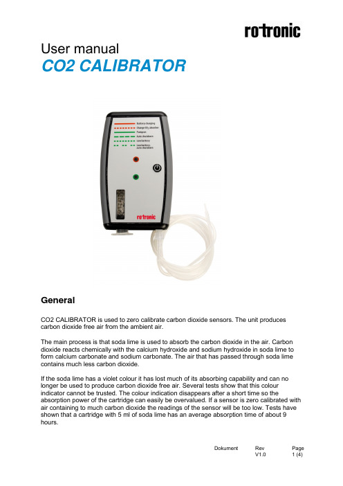
User manualCO2 CALIBRATORGeneralCO2 CALIBRATOR is used to zero calibrate carbon dioxide sensors. The unit produces carbon dioxide free air from the ambient air.The main process is that soda lime is used to absorb the carbon dioxide in the air. Carbon dioxide reacts chemically with the calcium hydroxide and sodium hydroxide in soda lime to form calcium carbonate and sodium carbonate. The air that has passed through soda lime contains much less carbon dioxide.If the soda lime has a violet colour it has lost much of its absorbing capability and can no longer be used to produce carbon dioxide free air. Several tests show that this colour indicator cannot be trusted. The colour indication disappears after a short time so the absorption power of the cartridge can easily be overvalued. If a sensor is zero calibrated with air containing to much carbon dioxide the readings of the sensor will be too low. Tests have shown that a cartridge with 5 ml of soda lime has an average absorption time of about 9 hours.Function parametersBattery chargingThe red LED is lit with a fixed light when the battery is charged (no indications of any alarm) Change CO2 absorberThe CO2 absorbent cartridge needs to be replaced when red LED is flashing evenly. (The CO2 absorbent cartridge has been used more than 8.5 hours)Pump onThe green LED is lit with a fixed light when the pump is working (no indications of any alarm) PrealarmThe unit is operating and after 21 min the green LED starts to flash with long pulses. This indicates that the unit will shut down automatically within 4 min if operated on battery.The unit will continue to operate if the charger is used. The green LED will flash with long pulses but the unit will continue to operate.Low batteryThe unit is operating and the green LED starts to flash with short pulses. This indicates that the battery voltage is below 7,1V.Technical dataWeight258 grams included absorbent cartridge (8 grams)Length156mmWidth89mmThickness26mmGas flow out320-340ml/min(Gas flow can be changed between 50ml-350ml/min by hard ware)Volume of CO2 absorbent cartridgeThe volume with maximum filling = 7ml (marked size 5ml length=72.2 mm outer diameter=13.7 mm)The absorbent power of the absorbent cartridge is dependent of several factors, but the minimum operational time is 8.5 hours with soda lime from Scarlau.(Factors that affect the absorbent power is type of chemicals, packing density of chemicals the tilt of the unit and the suction/pressure of the pump)The average flow of the pump through an OBA8 sensor is 320ml/minFor best result the Zero Calibration Kit should be in operation a while after changing the CO2 absorbent cartridge so that the cartridge will stabilise.Battery performanceBattery type Li Ion 2/2S1-LP103450AR/SR 7,4V 1550mAh. 11,47WhCharging time is about 5.2-6 hours.The battery is charged during operationOperation time of the batteryOperation time by normal operation is 15 hours before the low battery alarm is activated. The battery will shut down automatically when the battery voltage is below 5,0V.Service life of the batteryThe service life of the battery is dependent of its discharging and charging cycles. The service life of the battery should be 1000 cycles before the capacity is below 85% if the charging current is 400mA and the discharging current is 80mA.The battery will last about four years with three cycles of discharges and recharges a week. (High storage temperatures or frequent cycles of discharges and charges may shorten the battery life)If the Zero Calibration Kit is in standby mode the battery should be charged at least once in a month. Before longer storage the battery should only be charged to about 75 %, four hours charging time.。
固定二氧化碳灭火系统操作说明中英文版

固定二氧化碳灭火系统操作说明中英文版摘要:一、前言二、二氧化碳灭火系统简介三、操作说明1.准备工作2.系统启动3.灭火操作4.系统停止5.注意事项四、英文版操作说明正文:【前言】二氧化碳灭火系统是一种常见的消防设备,用于扑灭火灾。
本文将为您提供固定二氧化碳灭火系统的操作说明,包括准备工作、系统启动、灭火操作、系统停止和注意事项。
此外,我们还将提供操作说明的英文版。
【二氧化碳灭火系统简介】二氧化碳灭火系统是一种利用二氧化碳气体灭火的设备,具有灭火速度快、不留残留物、不损害设备等优点。
它适用于扑灭电气设备、液体、气体和油脂等火灾。
【操作说明】1.准备工作在使用二氧化碳灭火系统前,请确保系统处于正常工作状态。
检查系统组件,如阀门、喷嘴、压力表等,确保其完好无损。
同时,要确保二氧化碳气体瓶充足,并定期进行充装。
2.系统启动在火灾发生时,立即启动二氧化碳灭火系统。
操作员应迅速找到灭火控制盘,并按下“启动”按钮。
此时,系统将自动打开阀门,释放二氧化碳气体进行灭火。
3.灭火操作在二氧化碳气体释放过程中,操作员应保持安全距离,避免直接吸入过量气体。
同时,要密切监测火势,确保火灾得到有效扑灭。
4.系统停止当火灾被扑灭后,操作员应立即关闭二氧化碳灭火系统。
操作方法与启动时相同,即按下“停止”按钮。
此时,系统将自动关闭阀门,停止释放二氧化碳气体。
5.注意事项- 在操作过程中,务必确保人员安全,避免直接接触二氧化碳气体。
- 系统使用后,要进行详细检查,确保所有组件完好无损。
- 定期对系统进行维护和检修,确保其处于良好的工作状态。
联物CO2-T-S中文版(终稿)
联物壁挂CO2变送器®型号:CO2/T/S产品规格0-10V/4-20mA输出跳线设置◆ 短电后打开面壳,看见在电路板的右下侧有两组跳线J1及S1、S2。
见图4所示。
◆ 0-10V输出设置:J1断开, S1、S2的下两针短封。
◆ 4-20mA输出设置:J1短封,S1、S2的上两针短封。
注意事项:1.运输和安装时,请勿剧烈摇晃或碰撞本变送器,以防止损坏内置的CO2传感器或使其红外接收装置偏移。
2.当打开此CO2变送器面壳时,请勿随意拆卸上面的CO2电路模块,除非在我公司专业工程师的指导下。
以免二氧化碳传感器的损坏。
3.请注意以下CO2变送器自校验的情况:◆首次使用CO2变送器;◆或将CO2变送器长时间放置后使用;◆或CO2测量值不准确(与正确的CO2检测设备数据相比,或将变送器置于CO2浓度350-450PPM的室外环境下)。
ABC Logic TM自校验系统会遵循以下方式启动:◆将CO2变送器通电2天,以便ABC Logic TM自校验系统启动操作。
◆2天后若CO2变送器测量值(模拟量输出测量值)超出是级精度,你需要增加自校验时间。
典型的14天校准方法:在14天中,将CO2变送器放置于室外或无人居住的房间内(CO2浓度在400PPM左右)。
每次讲CO2变送器通电放置至少4小时,同时测量CO2变送器模拟量输出值。
若CO2浓度在精确范围内,则测量为准确值。
注意:a. 当校准过程中,传感器周围50公分内出现手机信号和广播信号,将影响传感器校准工作,导致校准值不准确。
b. 当见测模拟量输出数值时,请避免呼吸时直接将呼出气体面对CO2变送器。
连接至输出端子的接线请保持在1米以上,当CO2变送器启动10分钟并稳定后,请通过延长线检测模拟量信号。
CO2操作说明书

首先至少用大量的水冲洗5分钟以上,然后按照烫伤治疗。立即寻医处理。
安全
在大气中CO2以一种气态形式存在,它是一种无色,无嗅,无味的气体。在空气中达到一定浓度它将导致鼻子,眼睛,嘴巴有刺痛的感觉。浓度大于设置极限5000ppm将会导致严重的危险。
空气中CO2浓度达到10%人仅仅能呆几分钟。
产制造商名称、制造编号、建造时间、能力、压力、端点
压力及转数。
这些标牌在任何情况下不得移开、卸下或损坏,以防止
丢失有关数据信息。
-安全装置不得被关闭,否则将无法发挥功用。
排放压力的调节设定不能被改变。
-其它安全装置如温度和压力等均经特殊调节设定。这些
调节设定不能被改变。
-在机器设备上方工作时,开关柜的主开关必须断开。
安全
除沫器、气囊、水洗塔、负压和过压保护装置。
CO2-压缩机
CO2活性碳过滤器和干燥器
液化系统
纯化系统
CO2-储存罐
CO2-汽化器
CO2的物理性质
分子量:44.1
气态,在0°C,1,013bar时的密度:1.977kg/m3
饱和状态,在-27°C,16bar时的密度:40.8kg/m3
液体在-27°C,16bar时的密度:1062kg/m3
二、触摸屏主界面
此界面显示系统报警信息。
此界面显示系统报警历史。
技术描述
除沫器
功能
除沫器可以洗去发酵气中的糖和泡沫,避免泡沫进入到
CO2回收系统中。这一过程都是通过水来完成的,除沫器里的水来自于两个部分:一是由水泵从水洗塔泵到除沫器;二是来自于食品级的自来水,水进入除沫器的喷嘴里,洗涤完的水从除沫器里的水封溢出。从发酵来的原料气,首先进入除沫器。因为这原料气里含有许多不同的杂质,CO2气在进入压缩机之前,它是有必要去清洗此原料气的。
最新二氧化碳化学品安全技术说明书
化学品安全技术说明书产品名称:二氧化碳按照GB/T 16483、GB/T17519编制最新版修订日期:2015年7月6日SDS编号:******版本:******第1部份化学品及企业标识化学品中文名称:二氧化碳别名:碳酸酐化学品英文名称:Carbon dioxide企业名称:******************企业地址:*****************电话号码:********电子邮件地址:**********应急咨询电话:**********邮编:********传真:**********产品推荐和限制用途:用于制糖工业、制碱工业、制铅白等,也用于冷饮、灭火及有机合成。
第2部份危险性概述紧急情况概述:性质稳定,不燃烧,也不助燃。
在低浓度时,对呼吸中枢呈兴奋作用,高浓度时则产生抑制甚至麻痹作用。
中毒机制中还兼有缺氧的因素。
对环境有影响。
GHS危险性类别:加压气体特异性靶器官毒性-一次接触类别3(麻醉效应)标签要素:象形图:警示词:警告危险性说明:含压力下气体,如受热可爆炸; 可能引起呼吸道刺激,可能引起昏昏欲睡或眩晕。
防范说明:·预防措施:——远离热源和火源;避免阳光直射。
——使容器保持密闭,置于阴凉处。
——在储存和运输时与还原剂和细粉末状金属等分离开;在运输中钢瓶上要加装安全帽和防震橡皮圈,穿防护服和戴手套。
·事故响应:——吸入:将人员移至空气清新处,若呼吸困难,则输氧。
若停止呼吸,采用人工呼吸,就医。
——食入:无意义——皮肤接触:若有冻伤,就医。
——眼睛接触:若有冻伤,就医。
——灭火剂:本品不燃。
·安全储存:——在通风良好处储存;——应远离火种、热源,防止阳光直射;——应与易燃物或可燃物分开储存;——气瓶受热有爆炸危险气瓶储运应轻装、轻卸,防止钢瓶及附件破损。
·废弃处置:——不可擅自将残留的或未用的产品向室内、人群处排放。
可将二氧化碳缓慢的向室外高处排放至大气中。
CO2系统使用说明书new

气体自动灭火系统系列产品使用说明书第一册高压二氧化碳自动灭火系统浙江金盾消防器材有限公司ZHEJIANG JINDUN FIRE EQUIPMENT CO., LTD.金盾消防 ○R 2011版目录0.简介 (2)1.标准、规范及引用文件 (2)2.二氧化碳灭火系统工作流程图: (2)3.QME型有管网高压二氧化碳自动灭火系统 (3)3.1系统组成: (3)3.2系统部件结构及技术参数 (4)3.2.1灭火剂瓶组 (4)3.2.2驱动气瓶组 (4)3.2.3选择阀 (6)3.2.4气体单向阀 (7)3.2.5液体单向阀 (7)3.2.6压力信号反馈装置 (7)3.2.7集流管 (8)3.2.8称重装置 (9)3.2.9喷头 (9)3.2.10高压软管 (10)3.2.11控制气管和管接头: (11)3.2.12低泄高封阀 (11)3.2.13管道连接件 (11)3.3系统安装与调试 (14)3.3.1 装置的安装 (14)3.3.2 管道系统的安装 (15)3.4系统使用与操作 (15)3.4.1 自动控制 (15)3.4.2 电气手动控制 (15)3.4.3 机械应急手动控制 (15)3.4.4 系统紧急停止 (15)3.4.5 系统测试 (16)3.4.6 系统复位 (16)3.5系统维护与保养 (16)3.6安全使用要求 (16)4.GQE系列无管网高压二氧化碳自动灭火系统 (18)4.1系统组成 (18)4.2系统部件及参数 (18)4.3系统安装与调试 (19)4.4系统使用与操作 (20)4.5系统维护与保养 (21)4.6安全使用要求 (21)0.简介二氧化碳对绝大多数物质没有破坏作用,灭火后不留痕迹、没有毒害、适用于扑救各种可燃、易燃液体和固体物质的火灾;灭火前可切断气源的气体火灾。
二氧化碳具有不导电、不玷污物品、没有水渍损失、灭火效果好且价廉等优点。
特别适用于图书、档案等珍贵资料库房、电子计算机房、变配电室、通讯机房、飞机库、汽车库、船舱、中心控制室等场所的火灾防护。
二氧化碳说明书
一、概述二氧化碳自动灭火系统是一种优良的灭火设备,经长期使用也得到证明。
它适用于电子计算机房、数据库、图书库、银行、仓库、食品库、烟草库、大型发电机、电缆隧道、船舶机舱、货舱、纺织机等生产作业、危险场所。
九十年代初国际上开始禁用破坏大气臭氧层的卤代烷产品以来,二氧化碳作为灭火剂,它具有不导电,灭火后不沾污物品,且价格低廉,产品易得等优点,是取代卤代烷灭火剂的理想产品。
我公司生产的ZE型二氧化碳自动灭火系统是按国家现行标准设计制造的,并经国家固定灭火系统和耐火构件质量监督检测中心检测合格的。
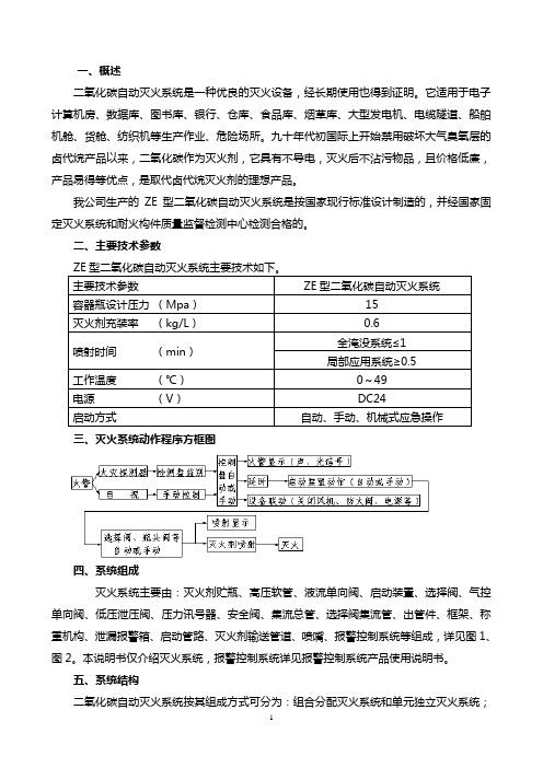
二、主要技术参数三、灭火系统动作程序方框图四、系统组成灭火系统主要由:灭火剂贮瓶、高压软管、液流单向阀、启动装置、选择阀、气控单向阀、低压泄压阀、压力讯号器、安全阀、集流总管、选择阀集流管、出管件、框架、称重机构、泄漏报警箱、启动管路、灭火剂输送管道、喷嘴、报警控制系统等组成,详见图1、图2。
本说明书仅介绍灭火系统,报警控制系统详见报警控制系统产品使用说明书。
五、系统结构二氧化碳自动灭火系统按其组成方式可分为:组合分配灭火系统和单元独立灭火系统;按其灭火方式可分为全淹没灭火系统和局部应用灭火系统;按其安装方式分为:固定式和半固定无管网式灭火系统。
1、全淹没灭火系统:是指在规定时间内,向固定封闭的防护区喷射一定浓度的二氧化碳,并使其均匀地充满整个防护区,实施灭火。
2、局部应用灭火系统:是指向保护对象以设计喷射率直接喷射二氧化碳灭火剂,并持续一段时间的灭火系统。
3、固定式灭火系统:是指将二氧化碳灭火设备固定在指定位置,有固定管网通向防护区的灭火系统。
4、半固定式无管网灭火系统:是指将二氧化碳灭火设备固定在防护区指定位置,且无固定管网的灭火系统。
5、组合分配灭火系统:是指采用一组二氧化碳灭火设备同时保护几个防护区的灭火系统。
其组成见图1。
6、单元独立灭火系统:是指采用一组二氧化碳灭火设备保护一个独立的防护区的灭火系统。
二氧化碳安全技术说明书标准版
二氧化碳安全技术说明书第一部分化学品及企业标识化学品中文名称:二氧化碳化学品英文名称:Carbon dioxide企业名称:企业地址:邮编: 传真:电子邮件地址:企业应急咨询电话:产品推荐用途及限制用途:金属焊接及冶炼、植物助长、电子工业等。
第二部分危险性概述紧急情况概述:不燃气体。
若遇高热,容器内压增大,有开裂和爆炸的危险。
GHS 危险性类别:根据化学品分类、警示标签和警示性说明规范系列标准(参阅第十五部分),该产品属于高压气体,类别压缩气体。
标签要素和象形图:警示词:警告危险信息:内装高压气体,遇热可能爆炸。
禁配物:水、碱性物质。
防范说明:预防措施:远离火种、热源。
密闭操作,提供良好的自然通风条件。
得到专门指导后操作。
防止气体泄漏到工作场所空气中。
远离易燃、可燃物。
避免高浓度吸入,高浓度接触时可佩戴空气呼吸器。
事故响应:如果吸入,迅速脱离现场至空气新鲜处。
保持呼吸道通畅。
如呼吸困难,给输氧。
呼吸、心跳停止,立即进行心肺复苏术。
就医。
安全储存:保持容器密闭。
储存于阴凉、通风的库房。
废弃处置:废气直接排入大气。
物理化学危险:内装高压气体,若遇高热,容器内压增大,有开裂和爆炸的危险。
健康危害:在低浓度时,对呼吸中枢呈兴奋作用, 高浓度时则产生抑制甚至麻痹作用。
中毒机制中还兼有缺氧的因素。
急性中毒,轻度中毒出现头晕、头痛、疲乏、恶心等,脱离接触后较快恢复。
人进入高浓度二氧化碳环境,在几秒钟内迅速昏迷倒下,反射消失、瞳孔扩大或缩小、大小便失禁、呕吐等,更严重者出现呼吸、心跳停止及休克,甚至死亡。
慢性影响经常接触较高浓度的二氧化碳者,可有头晕、头痛、失眠、易兴奋、无力等神经功能紊乱等。
但在生产中是否存在慢性中毒国内外均未见病例报道。
环境危害:该物质大量排放时对环境有影响第三部分成分/组成信息混合物□化学品名称:二氧化碳有害物成分浓度 CAS No二氧化碳≥ 99.0% 124-38-9第四部分急救措施皮肤接触:不会通过该途径受到伤害。
- 1、下载文档前请自行甄别文档内容的完整性,平台不提供额外的编辑、内容补充、找答案等附加服务。
- 2、"仅部分预览"的文档,不可在线预览部分如存在完整性等问题,可反馈申请退款(可完整预览的文档不适用该条件!)。
- 3、如文档侵犯您的权益,请联系客服反馈,我们会尽快为您处理(人工客服工作时间:9:00-18:30)。
联物壁挂CO2变送器®
型号:CO2/T/S
产品规格
0-10V/4-20mA输出跳线设置
◆ 短电后打开面壳,看见在电路板的右下侧有两组跳线J1及S1、S2。
见图4所示。
◆ 0-10V输出设置:J1断开, S1、S2的下两针短封。
◆ 4-20mA输出设置:J1短封,S1、S2的上两针短封。
注意事项:
1.运输和安装时,请勿剧烈摇晃或碰撞本变送器,以防止损坏内置的CO2传感器或使其红外接收装置偏移。
2.当打开此CO2变送器面壳时,请勿随意拆卸上面的CO2电路模块,除非在我公司专业工程师的指导下。
以免二氧化
碳传感器的损坏。
3.请注意以下CO2变送器自校验的情况:
◆首次使用CO2变送器;
◆或将CO2变送器长时间放置后使用;
◆或CO2测量值不准确(与正确的CO2检测设备数据相比,或将变送器置于CO2浓度350-450PPM的室外环境下)。
ABC Logic TM自校验系统会遵循以下方式启动:
◆将CO2变送器通电2天,以便ABC Logic TM自校验系统启动操作。
◆2天后若CO2变送器测量值(模拟量输出测量值)超出是级精度,你需要增加自校验时间。
典型的14天校准方法:在14天中,将CO2变送器放置于室外或无人居住的房间内(CO2浓度在400PPM左右)。
每次讲CO2变送器通电放置至
少4小时,同时测量CO2变送器模拟量输出值。
若CO2浓度在精确范围内,则测量为准确值。
注意:
a. 当校准过程中,传感器周围50公分内出现手机信号和广播信号,将影响传感器校准工作,导致校准值不准确。
b. 当见测模拟量输出数值时,请避免呼吸时直接将呼出气体面对CO2变送器。
连接至输出端子的接线请保持在1米
以上,当CO2变送器启动10分钟并稳定后,请通过延长线检测模拟量信号。