电话输入模块说明书
YC1008数字量输入输出模块使用说明书V1.0
YC1008数字量输入输出模块使用说明书V1.0目录一.模块介绍二.技术参数三.模块的型号四.模块尺寸、模块引脚定义、隔离特性五.模块使用说明六.通讯协议七.模块的MODBUS-RTU协议功能码与数据对应表版本记录:V1.0 2011-11-20 版本创建一.模块介绍YC1008数字量输入输出模块广泛应用于工业控制系统,具有广泛的使用意义。
YC1008模块的主要特点如下:1. YC1008系列模块通过隔离变压器和隔离光耦实现了供电电路、数字量输入、数字量输出、通讯电路的相互隔离,模块具有很强的稳定性和抗干扰能力。
2.单电源供电,隔离在模块内部通过隔离变压器和隔离光耦实现,隔离电压2500V。
3. YC1008系列模块实现8路数字量的输入和8路数字量的输出功能。
4. 通讯接口为RS485或232,通讯波特率等参数可配置,通讯协议为MODBUS-RTU。
二.技术参数供电电源1. 供电电压:DC12V或DC24V,电源反接保护。
2. 电流消耗:<35mA+继电器功耗。
数字量输入1. 共有8个数字量输入通道,可以接收多种输入信号:无源开关信号(逻辑0表示断开,逻辑1表示闭合);输入信号可以接集电极开漏(OC)输出信号、接近开关信号;输入信号也可以是有源信号(逻辑0表示3~35V,逻辑1表示0~0.5V表示闭合)。
2. 内部采用隔离变压器和隔离光耦实现了输入信号和电源的隔离,隔离电压2500V。
数字量输出1.8路数字量输出信号。
2.数字量输出通过继电器(常开触点)或集电极开漏输出(OC)两种方式实现。
3.该模块配有两种继电器输出:1) 继电器触点负载容量10A/277V AC;2) 继电器触点负载容量30A/240V AC。
4.继电器输出部分采用大电流铺铜设计,有利于大电流正常通过继电器。
5. 继电器触点负载容量30A/240V AC的相应端子选用管脚间距更大的端子,有利于提高高电压应用的安全性。
综合技术参数1. 通讯接口:RS485或RS232,通讯接口采用防雷和抗干扰设计,通讯接口光电隔离,隔离3000VDC。
TX3207输入/输出模块安装使用说明书

一、概述TX3207输入/输出模块(以下简称模块)符合国家标准GB16806-2006《消防联动控制系统》。
本模块用于控制具有动作信号输出的被动型消防设备(如:排烟口、送风口、防火阀等),负责将火灾报警控制器的联动指令传送给受控设备,再将受控设备的动作反馈信号传送回火灾报警控制器。
本模块外形美观,采用插拔式结构,方便施工安装;采用专用集成芯片,具有强大的分析判断能力,可对所连接受控设备的控制线(断路状态、短路状态)、反馈线(断路状态、短路状态)进行检测,并通过指示灯给出状态指示。
注意:在输入线的末端(远离模块端)必须并联一个10KΩ的终端电阻,否则控制器将报该模块的“反馈线故障”。
由于输出线接有受控设备作为负载,故无须配接终端电阻;不可断开受控设备做试验,否则控制器将报该模块的“输出线故障”。
若回路联动设备全部为此模块,最大带载数量为30个。
二、特点1.二总线,无极性2.采用专用集成芯片3.总线、输入线、输出线之间均采用隔离设计,减少外部干扰的影响4.输入可设置为常开或常闭模式5.无源触点输出6.软硬件多级滤波,提高抗干扰能力7.插拔式结构,方便施工安装三、技术参数1.总线协议:T3协议2.工作电压:总线电压:15~28V(脉冲电压)3.工作电流:总线监视电流:≤0.5mA总线动作电流:≤6.5mA4.指示灯:输入指示灯:红色(正常监视状态闪亮一次,故障状态闪亮两次,反馈状态常亮)输出指示灯:红色(动作状态常亮)5.编码方式:电子编码(占一个总线地址点,编码范围在1~242之间任意设定)6.输出容量:触点容量30V/2.0A7.终端电阻:10KΩ8.线制:无极性二总线9.使用环境:温度:-10℃~55℃相对湿度:≤95%RH,不凝露10.外形尺寸:86mm×86mm×33mm(含底座)11.重量:约98g(含底座)12.执行标准:GB16806-2006四、结构特征和工作原理1.模块的外形尺寸及安装尺寸如图1所示(单位:mm)。
JSM-M900M模块说明书

1
I56-900-03C
INSTALLATION AND MAINTENANCE INSTRUCTIONS
JSM-M900M INPUT MODULE
28 Tuan Jie South Road, Xi’an National Hi-tech Industrial Development Zone Province of Shaanxi, 710075, China
General Description
The JSM-M900M Input Module monitors the normally open contact fire alarm and supervisory devices.
Specifications
Operating Temperature Range: Operating Humidity Range: Operating Voltage Range: Standby Current:
外形尺寸: 124.6mm长x124.6mm宽x57.5mm高(模块与
预埋盒及面板安装尺寸,见图2B)
兼容性要求 为了确保正常工作,这些模块必须与兼容的控制器配
套使用。 安装 JSM-M900M可直接装入50mm深, 100mm见方的预埋盒内。 连线
注意:所有的连接线必须满足当地的法律、法规及有关条 例的要求。
Wiring
NOTE: All wiring must conform to applicable local codes, ordinances and regulations.
1. Set the address on the module as the drawing requirements. 2. All the wirings must be in accordance with the job drawing
MD231 模块 说明书
MD231模块使用手册V0.21简介 (3)1.1. 相关文档 (3)1.2. MD231模块简介 (3)1.3. MD231模块应用简介 (4)2 MD231模块使用 (4)2.1 MD231模块开机 (4)2.2 MD231模块关机 (4)2.3 MD231模块低功耗模式 (5)2.4 MD231模块串口流控 (5)2.5 MD231模块工作的异常处理 (6)3 MD231模块设计建议 (6)3.1 MD231接口板布线建议 (6)1简介本文档帮助客户更好的使用MD231的模块,从软件和硬件的角度介绍了MD231模块的使用指南,希望能让客户在最短的时间内用好MD231模块。
客户运用MD231有以下两类用法:1,把MD231当作标准的GSM/GPRS模块使用,客户通过Com口输入的AT命令使用模块,并从Com口得到模块的反馈信息,此类运用的客户需要外部MCU和Com相连。
2,客户把MD231运用在无线商话/公话等类似的GSM终端产品上,本公司帮客户定制的软件运行在MD231上,驱动LCD,键盘等外部设备,此类运用的客户不需要外部MCU。
本文档的主要是帮助第一类客户所写。
对于第二类客户,本文档的硬件PCB布板部分内容值得参考。
1.1. 相关文档[1] GSM 07.07: Digital cellular telecommunications (Phase 2+); AT command set for GSM Mobile Equipment (ME)[2] GSM 07.05: Digital cellular telecommunications (Phase 2+); Use ofData Terminal Equipment – Data Circuit terminatingEquipment (DTE –DCE) interface for Short MessageService (SMS) and Cell Broadcast Service (CBS) [3] GSM 11.14: Digital cellular telecommunications system (Phase 2+);Specification of the SIM Application Toolkit for theSubscriber Identity Module –Mobile Equipment (SIM –ME) interface[4] GSM 11.11: Digital cellular telecommunications system (Phase 2+);Specification of the Subscriber Identity Module –Mobile Equipment (SIM – ME) interface[5] AT_Document_FULL MD231模块AT指令集介绍[6] GPRS_PC_Env MD231模块PC设置介绍[7] MD231 Specification MD231模块硬件datasheet1.2. MD231模块简介MD231是双频GSM/GPRS模块;它可以工作在EGSM900/DCS1800 MHz或者GSM850/PCS1900 MHz频段上;并支持GPRS multi-slot class 10。
LD4400E-1输入模块安装使用说明书2009-06
LD4400E-1输入模块安装使用说明书(2009.06)北京利达华信电子有限公司B E I J I N G L E A D E R H U A X I N E L EC T R O N I C S C O.,L T D.目 录第一章概述 (2)第二章技术特性 (2)第三章结构特性与工作原理 (2)第四章安装与调试 (3)第五章使用与操作 (5)第六章故障分析与排除 (5)第七章注意事项 (5)第八章售后服务 (5)第一章概述LD4400E-1输入模块采用特殊防潮技术和插拔式结构设计。
内置单片机,适时处理采集的输入信息,工作性能稳定可靠,具有较强的抗干扰能力,满足GB16806-2006《消防联动控制系统》和《消防产品3C认证实施规则》。
可以接收常开无源接点的动作信号,如:水流指示器、压力开关、感温电缆等的动作信号。
可以和利达公司生产的E/EN系列火灾报警控制器配合使用。
也可以接收可燃气体探测器、紫外火焰探测器等报警后给出的无源接点的动作信号。
本产品无污染、功耗低,适用于各种工业及民用建筑。
第二章技术特性2.1 特性★ 二总线,无极性★ 采用电子编码,占一个节点地址(0~255)★ 单色指示灯:红色闪亮,显示动作信息★可接收无源开关接点信号★可检测无源开关接点线路断线故障2.2 主要技术指标工作电压:DC 14V~24V 静态电流:< 0.5mA报警电流:<1.5 mA 输入信号参数:无源开关量信号输入工作环境温度:0℃~45℃ 工作环境相对湿度:≤95%RH(40±2℃)第三章结构特性与工作原理3.1 工作原理LD4400E-1输入模块与LD128E/EN 系列控制器配合使用,LD4400E-1输入模块通过二总线与控制器相连,控制器通过二总线查询模块工作状态、设置模块;模块实时检测输入信号,通过二总线上传输入信号状态。
3.2 结构特性3.2.1 外形尺寸见图3-1、3-2所示:100mm×87mm×40m(单位:mm)3.2.2 安装尺寸如图3-3所示。
科韵创新电话通讯模块手册说明书

科韵创新电话通讯模块命名规则工作电压即可‐12 配套供电+12V ‐48 配套供电‐48V ‐R 配套供电‐75V铃流 A 、B、C 、D3 (+3.3V供电)5 (+5V供电)1 单通道2 双通道4 四通道8 八通道模块P 电源模块科韵创新深圳市科韵创新电子有限公司 四通道配套产品名录(3.3V工作电源、含CODEC系列)KT143A 中继接口KT143B 中继接口KT243B-12 用户接口KT243B-48 用户接口KT343A-R 磁石接口KT543B-12 综合接口KT543B-48 综合接口KT643A EM&二四线接口特点概述:1个模块内有4个独立通道单元、带PCM编解码、通过SPI接口实现检测与控制;(关于软件,我司可提供SPI接口代码、配置参数、控制检测接口软件)。
脚位兼容,方便配套使用,实现母板通用。
通软件可以识别出各种不同类型的模块,实现软件整合;工作电源为+3.3V ;A系列采用传统分立器件方案,编解码型号为LE58QL021。
B系列采用IC方案设计,内部资源丰富,所有参数软件可配置,适应全球应用;SIP18(或SIP18*2)+ SIP18封装,脚间距2.54mm;深圳市科韵创新电子有限公司 深圳市科韵创新电子有限公司 外型及脚位深圳市科韵创新电子有限公司 深圳市科韵创新电子有限公司 概述z KT143A是一种四通道中继接口模块。
它是采用传统方案设计,成本低。
采用的编解码芯片是LE58QL021。
z其通常叫FXO、中继、近端、外线、局端模块;z采用传统变压器、光耦进行隔离,抗干扰能力强;z内置雷击保护、电力线搭接保护(即过压、过流保护)功能;z挂机接收通道,支持来电显示传输;z电话线路状态检测(铃流检测、摘机极性检测);z2/4线变换;z PCM接口编解码;z SPI接口检测、控制、点电平调整;z线路摘机交流阻抗为国标三元件200+680//100nf;z工作电源+3.3伏。
AD7028 通讯模块使用手册说明书
AD7028通讯模块使用手册厦门爱陆通通信科技有限公司热线:400-808-5829电话:传真:网址:地址:厦门市集美区杏北二路146-148号、目录目录 (3)第1章产品简介 (5)1.1 产品概述 (5)1.2 产品特点 (5)1.3 工作原理框图 (6)1.4 产品规格 (7)1.5 订购信息 (8)第2章产品安装 (9)2.1 概述 (9)2.2 装箱清单 (9)2.3 安装与电缆连接 (9)2.4 电源说明 (12)2.5指示灯说明 (13)2.6 复位按钮说明 (13)第3章参数配置 (14)3.1 设备与PC连接图 (14)3.2 登录到配置页面 (14)3.2.1 PC机IP地址设置(两种方式) (14)3.2.2 登录到配置界面 (15)3.3 网络基本 (16)3.3.1 广域网 (16)3.3.2 广域网状态 (19)3.3.3 局域网 (19)3.3.4 局域网状态 (21)3.4 网络高级 (22)3.4.1 静态地址分配 (22)3.4.2 高级路由 (22)3.4.3 MAC地址克隆 (23)3.4.4 静态域名解析 (23)3.5 无线设置.......................................................................................... 错误!未定义书签。
3.5.1 基本设置............................................................................... 错误!未定义书签。
3.5.2 无线安全............................................................................... 错误!未定义书签。
3.5.3 无线状态............................................................................... 错误!未定义书签。
3011XP RDTU模块说明书
EN3011XP RDTU使用说明书、杭州易能控制工程有限公司杭州市振华路206号西港·新界5幢C座2层电话:(0571)88265086 传真:(0571)88265086-808邮箱:eneng@网址:目录第一章产品简介 (1)1.1产品概述 (2)1.2功能特点 (3)1.3技术参数 (4)第二章模块安装 (7)2.1概述 (7)2.2开箱 (7)2.3安装 (7)2.4供电电源 (9)2.4检测网络 (9)第三章终端设置 (10)3.1通讯连接 (10)3.2软件配置 (10)第四章使用说明 (20)4.1端子说明 (20)4.2面板指示灯 (20)4.3数据接口定义 (21)4.4拨位开关定义 (22)4.5故障分析 (22)第一章产品简介1.1产品概述EN3011XP RDTU是基于GPRS/CDMA数据通信网络的终端产品,为各行业用户提供稳定可靠、经济实用的专用数据网络。
手机是通过语音或者短信的传输使人们建立起沟通的桥梁,而享有“工业手机”美誉的DTU则是机器与机器之间完全透明的数据传输终端设备。
本产品符合工业级标准,优化电磁兼容性设计,具有超强的可靠性;EN3011XP RDTU型数据采集终端内封装了TCP/IP 协议,提供 RS232/RS485 标准接口的双向透明数据传输,支持GPRS/CDMA两种通信方式,主要应用于数据采集和工业远程监控的各种场合。
模块具有体积小、重量轻、稳定性高、费用低廉、安装简单、抗干扰能力强等特点。
产品广泛应用于电力、环保监测、水利、路灯监控、热力管网、煤矿、油田等行业,该终端具有完善的断线自我重连功能。
1.2功能特点基本功能l支持GPRS、CDMA网络,内置GPRS或CDMA模块l内嵌标准的TCP/IP协议栈,数据终端永远在线l透明数据传输与协议转换l支持图形界面配置与维护l提供RS232/RS485标准串口l内建看门狗,异常自动恢复,保持系统稳定l方便的系统配置和维护接口增强功能l完善的通信链路维护功能,可设置长连接,定时连接等多种连接方式l完善的心跳机制,用户可以根据自身实际设置心跳包发送的时间间隔l TCP、UDP通信方式可选,用户可根据实际要求进行设置l通信流量统计功能,能为用户提供使用流量的参考l报警功能:每一路开关量信号均可设定为报警模式,能主动上报报警信息,可向设定的手机发送报警信息l智能上传:有一路信号均可设定一阀值,信号在阀值内变化,可较长时间发送,突破阀值可迅速发送数据,解决数据响应速度与通信流量间的矛盾l积算功能:对每路模拟量均可进行累计积算l估算功能:能对脉冲累计量进行估算其瞬时量l即插即用功能:对于出厂的模块,不需任何设置,即可自动连接到用户软件,方便用户的使用l支持短信参数配置、重启动控制l支持ModBus、Hart等多种通信协议工业级设计,满足恶劣环境需求l提供标准OPS SERVER、DDE接口,兼容各种组态软件,包括Wincc、Intouch、iFix、RSView、组态王、MCGS、力控等l校时:能响应系统的校时命令,统一时钟。
XBE-DN32A 16点DC输入模块说明书
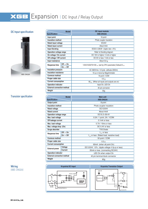
88DC Input specificationTransistor specificationWiring(XBE-DN32A)XBE-DN32ADC 6V or less / 1mA or less About 5.6AC 560Vrms / 3 Cycle (altitude 2000m)10or more by Megohmmeter 16 point / COM 0.360(When all inputs and outputs are on)Input On, LED On 1/3/5/10/20/70/100(set by CPU parameter) Default:3TVS Diode 1or less 1or less (Rated load, resistive load)32 point / COM 0.360mA (when all point On)DC12/24V 10% (ripple voltage 4 Vp-p or less)89SpecificationNames and FunctionsXBF-AD04AXBF-AD04CWiring 0~100001/16000(0~5V)-10000~10000(10V)APPLICSTION90SpecificationNames and Functions WiringXBF-DV04AXBF-DV04CXBF-DC04C911.25mV (DC 1~5V, 0~5V),2.5mV (DC 0~10V)5(DC 4~20mA, 0~20mA)SpecificationNames and FunctionsWiring XBF-AH04AAPPLICSTION92SpecificationWiring XBF-RD04ANames and Functions93SpecificationNames and Functions Wiring XBF-TC04SAPPLICSTION94-200.0 ~ 1300.00.0 ~ 500.0-200.0 ~ 1200.00.0 ~ 500.0-200.0 ~ 800100ppm/(0.01%/)Automatic compensation by RJC sensing2.0500ms/ 4 loopPID CONTROL, ON/OFF CONTROL20 minutes or above0.5 /min (30 /hour) or less16 point terminal (10 point terminal 1ea, 6 point terminal 1ea)Fixed: 64 points0.2% or less (25 , normal temperature,except -200~-100 for the T type)Insulation resistor: 500V DC, 10 M or aboveSpecificationXBF-TC04TT95-200.0 ~ 850.0 -200.0 ~ 600.0 0.2% or less (25 , normal temperature)100ppm/ (0.01%/ )500ms/ 4 loop PID CONTROL, ON/OFF CONTROL SpecificationXBF-TC04RT Insulation resistor: 500V DC, 10 M or aboveAPPLICSTION962 Channel (Insulation between Channels)5VDC 5%, (8 per 350load cell channel)Four-wire or Six-wire1/400000.0~6.00.125(when the rated output of the load cell is 0.0 ~ 1.0/ V)5V, DC 24Internal DC5V : 110External DC24V : 2805SpecificationXBF-LD02S0.01% or below (nonlinear accuracy, 25)Zero Drift: 0.25Gain Drift: 15ppm//DC500 V,10 M orabove Insulation Insulation Voltage Resistance(Internal Test Specifications)97APPLICSTIONSpecificationNames and Functions XBF-PD02ATerminal98Switching controlSpecificationXBF-PN08B-214748364.8~214748364.7()-21474.83648~21474.83647-214748364.8~214748364.7()-21474.83648~21474.83647-214748364.8~214748364.7()-21474.83648~21474.8364799APPLICSTIONNames and FunctionsTerminal100SpecificationXBF-HO02AXBF-HD02ANames and Functions101APPLICSTIONTerminal (XBF-HO02A)A+A-A+A-B+B-B+B-P 24VP 12VA phase differentiation input +A phase differentiation input -A phase differentiation input +A phase differentiation input -B phase differentiation input +B phase differentiation input -B phase differentiation input +B phase differentiation input -Terminal (XBF-HD02A)102Ethernet (XBL-EMTA)RAPIEnet (XBL-EIMT)XBL-C21AXBL-C41ARS-232C, RS-422 / 485103APPLICSTIONEthernet/IP (XBL-EIPT)Main unit scan 2 + Data receive time + Communication module scan XG5000 (setting station and high-speed link parameter block)Profibus-DP Module (XBL-PMEC, XBL-PSEA)104Thin Cable Terminal resistance ()125 kbps 250 kbpsCSMA/NBA Poll type Up to 64 (including master) MAC IDs (MAC Identifier)Insertion and removal of nod available in voltage On status Terminal resistance ()Master/Slave operation Data Processing unit XG5000 : High Speed Link Monitoring 110(5%), 1/2W Only available as Master Byte Rnet (XBL-RMEA)DeviceNet Module (XBL-DSEA)Trunk/drop line Power/Signal cable inside the identical network cable105APPLICSTIONCANopen Module (XBL-CMEA, XBL-CSEA)106Smart linkConnection cable Terminal board Option modules107APPLICSTION Program editing & Engineering software Windows-based easy operation Multi-PLC, Multi-programming support Various monitoring and diagnosis functions Convenient network settingExtended monitoring function for network system and communication modules Fast interface with CPU by effective network managementVarious built-in diagnosis, functions(CPU condition, Link conditon, Service condition, Frame monitoring)Trend monitor Special module monitor Ladder monitor Forced I/O Variable monitor Parameter setting Service conditionmonitoringNetwork scan Frame monitoring XGT PanelLink monitoringFast ethernetSmart I/O Other PLCOther netdevicsLS Inverter XG5000(Programming software)XG-PD (Network setting software)108Main SpecificationAluminum body frame, responsive touch screen.Easy-to-use Multi-touch, gesture, dual screen, portrait mode. Multi connected with 1Gbits 2ch. Ethernet between PC to PLC.Various interfaces : USB host /device, SD card, HDMI. High resolution : 1024 X 768IP66, UL type 4x, NEMA 4x standardsDate/Hour data, Logging/Alarm/Recipe data and nonvolatile device Approx. 3 years (Operating ambient temperature of 2577)109APPLICSTIONMain Specification1GHz 32bit RISC Embedded CPU 16,777,216 TFT color LCD128MB display data and1MB back-up memory Ethernet 1ch, RS-232C 2ch, RS-422/485 1ch USB host 3ch and device 1chSD memory card interfaceMain FunctionsPLC ladder monitoring (XGK/XBC PLC only)Web Server/Data Server Path through XP-Remote :Remote controlling and monitoringDate/Hour data, Logging/Alarm/Recipe data and nonvolatile device Approx. 3 years (Operating ambient temperature of 25)and USB memory driver is available)110Main SpecificationTFT LCD-applied wide typeLED Backlight adopted for enhanced contrast ratio and low-powerPLC Ladder monitoring function: Only XGK/XBC supports*Web Server* / Data Server* / Path-Through Function*Remote Viewer Function*Screen editor : XP-BuilderFunctions that support only the TTA modelDate/Hour data, Logging/Alarm/Recipe data and nonvolatile deviceApprox. 3 years (Operating ambient temperature of 50)Time error Approx. 3 sec/1day(Operating ambient temperature of 25)1 channel, USB 2.0 Host (mouse, keyboard, printer and USB memory driver is available)4.6W7.2W 6.5W10W12810232165.0132.536.1165.0132.536.1156.0123.5208.0154.044.4192.0138.0276.0218.044.4260.0202.01 channel, IEEE802.1a, 10Base-T/100Base-TX111APPLICSTIONGraphic type XP30/XP40/XP50/XP70/XP80/XP90High and vivid distinction with 65,536 colors High quality raster and vector symbolsVarious BMP JPG GIF graphic file support: BMP, JPG, GIF, WMF, etc Simple animation effects: animated GIF 10/100BASE-T Ethernet interface Convenient and easy screen editingStrengthened data management: Logging, Recipe, and Alarm Read function of a controller’s state information: Monitoring and maintenanceMulti-lingual display: up to 8 languagesOffline and concurrent simulation with XG5000 Easy to change the address of the graphic objects: Tag function with XGT PanelUSB host for peripheral devices: USB Drive, Mouse, keyboard, printer, etcSufficient memory for screen data: 10MB112Text type XP10Screen: 192 64 Graphic STN LCDSystem RAM: 1000 wordsFlash memory: Program/Parameter back upCommunication: Half-duplex comm.- Baud rate: 1200~115200 bps - Master/slave setting available- RS-232C/RS-485 2 CH separate to usePower reguirements - 24 V input or 5 V direct input by LS PLC Various function key - ESC, ALM, SET, ENT, F1~F4, Arrow keys Panel Editor - Easy programming and H/W settingKey to control PLC device and screen ESC key Alarm historyData input and Screen change PLC data setting Enter keyDC24V input terminalRS-232C port to download a project Brightness adjustment RS-422 port115,200bps12 Keys (F1~F4, ESC, ALM, ,113APPLICSTIONProduct list114Product list。
NI 9208 16通道、±20mA、24位模拟输入模块数据手册说明书

DAT ASHEET NI 920816-Channel, ±20 mA, 24-Bit Analog Input Module•16 channels, current inputs,500 S/s•High-resolution mode with50/60 Hz rejection; Vsuppins for external powerrouting (2 A/30 V max)•±20 mA, 24-bit resolution•250 Vrms, CAT II, channel-to-earth isolation (springterminal); 60 VDC, CAT I,channel-to-earth isolation(DSUB)•DSUB or spring-terminalconnectivity•-40 °C to 70 °C operatingrange, 5 g vibration, 50 gshockThe NI 9208 current input C Series module has 16 channels of ±20 mA input with built-in50/60 Hz rejection for noise rejection.The NI 9208 has a standard 37-pin DSUB connection for use with available cables and connector blocks, or the NI 9937 DSUB connector kit. The NI 9937 contains a DSUB to screw terminal accessory as well as a protective shell. With this kit, you can create a custom cable that plugs directly into the module, eliminating the need for a separate terminal block.Kit ContentsAccessories• NI 9208• NI 9208 Getting Started Guide• NI 9940 Backshell Connector Kit (Spring Terminal)• NI 9923 Screw-Terminal Block (DSUB)NI C Series OverviewNI provides more than 100 C Series modules for measurement, control, and communication applications. C Series modules can connect to any sensor or bus and allow for high-accuracy measurements that meet the demands of advanced data acquisition and control applications.•Measurement-specific signal conditioning that connects to an array of sensors and signals •Isolation options such as bank-to-bank, channel-to-channel, and channel-to-earth ground •-40 °C to 70 °C temperature range to meet a variety of application and environmental needs•Hot-swappableThe majority of C Series modules are supported in both CompactRIO and CompactDAQ platforms and you can move modules from one platform to the other with no modification. CompactRIOCompactRIO combines an open-embedded architecturewith small size, extreme ruggedness, and C Seriesmodules in a platform powered by the NI LabVIEWreconfigurable I/O (RIO) architecture. Each systemcontains an FPGA for custom timing, triggering, andprocessing with a wide array of available modular I/O tomeet any embedded application requirement. CompactDAQCompactDAQ is a portable, rugged data acquisition platformthat integrates connectivity, data acquisition, and signalconditioning into modular I/O for directly interfacing to anysensor or signal. Using CompactDAQ with LabVIEW, youcan easily customize how you acquire, analyze, visualize, andmanage your measurement data.2| | NI 9208 DatasheetSoftwareLabVIEW Professional Development System for Windows•Use advanced software tools for large project development•Generate code automatically using DAQ Assistant and InstrumentI/O Assistant•Use advanced measurement analysis and digital signal processing•Take advantage of open connectivity with DLLs, ActiveX, and .NETobjects•Build DLLs, executables, and MSI installersNI LabVIEW FPGA Module•Design FPGA applications for NI RIO hardware•Program with the same graphical environment used for desktop andreal-time applications•Execute control algorithms with loop rates up to 300 MHz•Implement custom timing and triggering logic, digital protocols, andDSP algorithms•Incorporate existing HDL code and third-party IP including Xilinx IPgenerator functions•Purchase as part of the LabVIEW Embedded Control and MonitoringSuiteNI LabVIEW Real-Time Module•Design deterministic real-time applications with LabVIEWgraphical programming•Download to dedicated NI or third-party hardware for reliableexecution and a wide selection of I/O•Take advantage of built-in PID control, signal processing, andanalysis functions•Automatically take advantage of multicore CPUs or setprocessor affinity manually•Take advantage of real-time OS, development and debuggingsupport, and board support•Purchase individually or as part of a LabVIEW suiteNI 9208 Datasheet| © National Instruments| 3CircuitryV VThe input signals are scanned, amplified, conditioned, and then sampled by a single 24-bit ADC. The module provides overvoltage protection for each channel. Only one channel can be in an overvoltage condition at a time.NI 9208 SpecificationsThe following specifications are typical for the range -40 °C to 70 °C unless otherwise noted.All voltages are relative to COM unless otherwise noted.Caution Do not operate the NI 9208 in a manner not specified in this document.Product misuse can result in a hazard. You can compromise the safety protection built into the product if the product is damaged in any way. If the product is damaged, return it to NI for repair.Input CharacteristicsNumber of channels 16 analog input channels ADC resolution 24 bits Type of ADC Delta-Sigma Sampling mode ScannedInput rangeMinimum ±21.5 mA Typical±22 mA4 | | NI 9208 DatasheetConversion time (per channel)High-resolution mode52 msHigh-speed mode 2 msOvervoltage protection, channel-to-COM±30 V maximum on one channel at a time Vsup pinsCurrent 2 A maximumV oltage30 V maximumInput impedance85 ΩInput noiseHigh-resolution mode50 nArmsHigh-speed mode200 nArmsStabilityGain drift20 ppm/°COffset drift62 nA/°CNMRR (High-resolution mode only)50 Hz66 dB60 Hz68 dBPower RequirementsPower consumption from chassisActive mode282 mW maxSleep mode25 μW maxThermal dissipation (at 70 °C)Active mode 1.29 W maxSleep mode0.72 W max1Range equals 22 mANI 9208 Datasheet| © National Instruments| 5Physical CharacteristicsIf you need to clean the module, wipe it with a dry towel.Tip For two-dimensional drawings and three-dimensional models of the C Seriesmodule and connectors, visit /dimensions and search by module number.Push-in spring-terminal wiringGauge0.14 mm2 to 1.5 mm2 (26 AWG to 16 AWG)copper conductor wireWire strip length10 mm (0.394 in.) of insulation stripped fromthe endTemperature rating90 °C minimumWires per spring terminal One wire per spring terminal; two wires perspring terminal using a 2-wire ferrule Ferrules0.14 mm2 to 1.5 mm2Connector securementSecurement type Screw flanges providedTorque for screw flanges0.2 N · m (1.80 lb · in.)WeightNI 9208 with spring terminal161 g (5.7 oz)NI 9208 with DSUB144 g (5.1 oz)NI 9208 with Spring Terminal Safety VoltagesConnect only voltages that are within the following limits:IsolationChannel-to-channel NoneChannel-to-earth groundContinuous250 Vrms, Measurement Category IIWithstand up to 4,000 m3,000 Vrms, verified by a 5 s dielectricwithstand testMeasurement Category II is for measurements performed on circuits directly connected to the electrical distribution system. This category refers to local-level electrical distribution, such as that provided by a standard wall outlet, for example, 115 V for U.S. or 230 V for Europe.Caution Do not connect the NI 9208 to signals or use for measurements withinMeasurement Categories III or IV.6| | NI 9208 DatasheetNI 9208 with DSUB Safety VoltagesConnect only voltages that are within the following limits:IsolationChannel-to-channel NoneChannel-to-earth groundContinuous60 VDC, Measurement Category IWithstand up to 2,000 m1,000 Vrms, verified by a 5 s dielectricwithstand testMeasurement Category I is for measurements performed on circuits not directly connected to the electrical distribution system referred to as MAINS voltage. MAINS is a hazardous live electrical supply system that powers equipment. This category is for measurements of voltages from specially protected secondary circuits. Such voltage measurements include signal levels, special equipment, limited-energy parts of equipment, circuits powered by regulated low-voltage sources, and electronics.Caution Do not connect the NI 9208 with DSUB to signals or use formeasurements within Measurement Categories II, III, or IV.Note Measurement Categories CAT I and CAT O are equivalent. These test andmeasurement circuits are not intended for direct connection to the MAINS buildinginstallations of Measurement Categories CAT II, CAT III, or CAT IV. Hazardous LocationsU.S. (UL)Class I, Division 2, Groups A, B, C, D, T4;Class I, Zone 2, AEx nA IIC T4Canada (C-UL)Class I, Division 2, Groups A, B, C, D, T4;Class I, Zone 2, Ex nA IIC T4Europe (ATEX) and International (IECEx)Ex nA IIC T4 GcSafety and Hazardous Locations StandardsThis product is designed to meet the requirements of the following electrical equipment safety standards for measurement, control, and laboratory use:•IEC 61010-1, EN 61010-1•UL 61010-1, CSA 61010-1•EN 60079-0:2012, EN 60079-15:2010•IEC 60079-0: Ed 6, IEC 60079-15; Ed 4NI 9208 Datasheet| © National Instruments| 7•UL 60079-0; Ed 6, UL 60079-15; Ed 4•CSA 60079-0:2011, CSA 60079-15:2012Note For UL and other safety certifications, refer to the product label or the OnlineProduct Certification section.Electromagnetic CompatibilityThis product meets the requirements of the following EMC standards for electrical equipment for measurement, control, and laboratory use:•EN 61326-1 (IEC 61326-1): Class A emissions; Industrial immunity•EN 55011 (CISPR 11): Group 1, Class A emissions•EN 55022 (CISPR 22): Class A emissions•EN 55024 (CISPR 24): Immunity•AS/NZS CISPR 11: Group 1, Class A emissions•AS/NZS CISPR 22: Class A emissions•FCC 47 CFR Part 15B: Class A emissions•ICES-001: Class A emissionsNote In the United States (per FCC 47 CFR), Class A equipment is intended foruse in commercial, light-industrial, and heavy-industrial locations. In Europe,Canada, Australia and New Zealand (per CISPR 11) Class A equipment is intendedfor use only in heavy-industrial locations.Note Group 1 equipment (per CISPR 11) is any industrial, scientific, or medicalequipment that does not intentionally generate radio frequency energy for thetreatment of material or inspection/analysis purposes.Note For EMC declarations and certifications, and additional information, refer tothe Online Product Certification section.Caution For EMC compliance, operate the NI 9208 with DSUB with shieldedcables.CE ComplianceThis product meets the essential requirements of applicable European Directives, as follows:•2014/35/EU; Low-V oltage Directive (safety)•2014/30/EU; Electromagnetic Compatibility Directive (EMC)•2014/34/EU; Potentially Explosive Atmospheres (ATEX)Online Product CertificationRefer to the product Declaration of Conformity (DoC) for additional regulatory compliance information. To obtain product certifications and the DoC for this product, visit /8| | NI 9208 Datasheetcertification, search by model number or product line, and click the appropriate link in the Certification column.Shock and VibrationTo meet these specifications, you must panel mount the system.Operating vibrationRandom (IEC 60068-2-64) 5 g rms, 10 Hz to 500 HzSinusoidal (IEC 60068-2-6) 5 g, 10 Hz to 500 HzOperating shock (IEC 60068-2-27)30 g, 11 ms half sine; 50 g, 3 ms half sine;18 shocks at 6 orientations EnvironmentalRefer to the manual for the chassis you are using for more information about meeting these specifications.Operating temperature-40 °C to 70 °C(IEC 60068-2-1, IEC 60068-2-2)-40 °C to 85 °CStorage temperature(IEC 60068-2-1, IEC 60068-2-2)Ingress protection IP40Operating humidity (IEC 60068-2-78)10% RH to 90% RH, noncondensing Storage humidity (IEC 60068-2-78)5% RH to 95% RH, noncondensing Pollution Degree2Maximum altitudeFor NI 9208 with spring terminal4,000 mFor NI 9208 with DSUB2,000 mIndoor use only.Environmental ManagementNI is committed to designing and manufacturing products in an environmentally responsible manner. NI recognizes that eliminating certain hazardous substances from our products is beneficial to the environment and to NI customers.For additional environmental information, refer to the Minimize Our Environmental Impact web page at /environment. This page contains the environmental regulations and directives with which NI complies, as well as other environmental information not included in this document.NI 9208 Datasheet| © National Instruments| 9Waste Electrical and Electronic Equipment (WEEE) EU Customers At the end of the product life cycle, all NI products must bedisposed of according to local laws and regulations. For more information abouthow to recycle NI products in your region, visit /environment/weee.电子信息产品污染控制管理办法(中国RoHS)中国客户National Instruments符合中国电子信息产品中限制使用某些有害物质指令(RoHS)。
NI 9402 数字输入 输出模块说明书

数据表NI 94024 DIO, LVTTL ,双向,55 ns•BNC 连接•CompactDAQ 计数器兼容性•可单独配置通道方向NI 9402为数字输入/输出模块,可用于任意CompactDAQ 及CompactRIO 系统。
可对每个通道配置通道方向为输入或输出。
通道和背板间,每个通道瞬态隔离为1000 Vrms 。
使用CompactRIO ,可以用LabVIEW FPGA 模块对NI 9402进行编程,实现定制的高速计数器/定时器、数字通信协议、脉冲发生、以及更多其他功能。
• NI 9402• NI 9402入门指南• NI 9940 后壳套件 (779567-01) 套件内容附件• BNC ~ BNC 公口线缆 (779697-02)NI C 系列概述NI 提供超过100种C 系列模块,用于测量、控制以及通信应用程序。
C 系列模块可连接任意传感器或总线,并允许进行高精度测量,以满足高级数据采集及控制应用程序的需求。
•与测量相关的信号调理,可连接一组传感器和信号•隔离选项包括组间、通道间以及通道对地•温度范围为-40 °C ~70 °C ,满足各种应用程序和环境需要•热插拔CompactRIO 和CompactDAQ 平台同时支持大部分C 系列模块,用户无需修改就可将模块在两个平台间转换。
CompactRIOCompactRIO 将开放嵌入式架构与小巧、坚固以及C 系列模块进行了完美融合,是一种由NI LabVIEW 驱动的可重配置I/O (RIO )架构。
每个系统包含一个FPGA ,用于自定义定时、触发以及处理一系列可用的模块化I/O ,可满足任何嵌入式应用程序的需求。
2 | | NI 9402数据表CompactDAQCompactDAQ是一种便携、耐用的数据采集平台,其模块化I/O集成了连接、数据采集以及信号调理功能,可直接接入任意传感器或信号。
配合LabVIEW使用CompactDAQ,用户可轻松地定义如何采集、分析、可视化以及管理测量数据。
SM8301输入模块使用说明书

图4
额定电流: 输入特性: 执行标准: 认证标志: A 无源触点闭合 GB16806-2006 CCC 85mm 长×85mm 宽×39mm 高
长线多点接触不良的不规范接线将导致系统不稳定。 输入端终端电阻是否连 接上。 输入模块报反馈,应检查输入模块的输入端连线是否短路,或监视的 外部设备本身就有闭合信号输出。 模块在维修期间,应有备用品替换。 6、 运 输、 贮存 在符合包装要求和稳妥的情况下,允许以汽车、 火车、 轮船、 飞机等任 何方式运输; 包装箱外应贴有“小心轻放”、 “防潮防雨”、 “请勿倒置”等标志; 在环境温度 0℃~45℃,相对湿度 85%,无腐蚀气体,通风良好的条 件下,最大贮存期为六个月。在此期间开箱后,应能正常使用。 7、产品 成套 SM8301 输入模块 使用说明书 产品合格证 47K终端电阻 1只 1份 1份 1支
8、 保修 说明 西安西核彩桥实业科技有限公司对按说明书要求正确安装、操作、使用 情况下出现问题 的产品实行 18 个月保修。 如果是由于人为损坏、 使用不当或 保修期外产品出问题,不属于本保修范围,由此导致的后果我公司将不负责 任。
西安西核彩桥实业科技有限公司
地 址:中国·西安市高新区科技四路 192 号 电 话:029-88453472,88453531 传 真:029-88451639 邮政编码:710065
SM8301
输入模块
安装、维护及使用说明书
图1 图2 1、 概述 SM8301 输入模块是我公司按照 GB16806-2006 《消防联动控制系统》 研制 开发的新型产品,内置处理器,电子编码,与我公司 JB-QB-CH8000 火灾报 警控制器(联动型)连接。 用于火灾报警控制器对外部设备(如水流指示器、 压力开关等)的开关量报警信号的监视。 2、 结构特征与工作原理 采用拔插式结构,外形图见图 1、 图 2。先在底座上接线,再插入模块主 体面板,便于安装、维护。 输入模块占用 1 个总线地址。 处于正常监控时,红色“巡检”灯闪亮。 在 与报警控制器或外部监视设备间的连接线发生故障及该产品本身故障时,控 制器将报出该故障点。输入模块监视的外部设备动作,模块输入端接收到无 源闭合信号后,“动作”指示灯常亮,同时将信息上传给火灾报警控制器, 火灾报警控制器发出声、光报警并显示模块反馈信息。 图3 3、 技术条件 环境温度 -10℃~55℃ 相对湿度 95% (40±2℃) 工作电压: 额定电压 DC24V
宝利通POLYCOM-SoundStructure-C系列-电话模块添加中文说明书
Polycom® SoundStructure™ C16, C12, C8, and SR12中文说明书商标说明:Polycom®,是Polycom设计的商标, SoundPoint® IP, SoundStation®, SoundStation VTX 1000®,ViaVideo®, ViewStation®, and Vortex®是Polycom公司注册用的商标. Polycom HD Voice™,Conference Composer™, Global Management System™, ImageShare™, Instructor RP™, iPower™,MGC™, PathNavigator™, People+Content™, PowerCam™, Pro-Motion™, QSX™, ReadiManager™,Siren™, StereoSurround™, V2IU™, Visual Concert™, VS4000™, VSX®, SoundStructure™,和SoundStation用于工业设计的商标都是Polycom公司的.在美国和其他的国家所有其他的都是公司自己使用的.专利权信息:随附产品受美国和其它国家/ 地区的一项或多项专利和/ 或 Polycom, Inc. 正在申请的专利所保护。
免责声明:允许授予使用权, 免费, 对任何人获得这个软件和相关文件("软件的"), 对成交在软件没有制约, 包括没有局限权利使用, 复制, 修改, 合并, 出版, 分布, 技术转让, 并且/或者软件的出售拷贝, 和允许软件被安装到其他的机器, 依于以下条件:上述版权告示和这个允许通知将包括在所有软件的复制件或部分复制件。
© 2007 Polycom, Inc. All rights reserved.Polycom Inc.4750 Willow RoadPleasanton, CA 94588-2708USA未经 Polycom, Inc. 明确书面许可,不得以任何形式或通过任何电子或机械方式,复制或传播本文件的任何部分用于任何用途。
JBF5131A型输入模块使用说明书
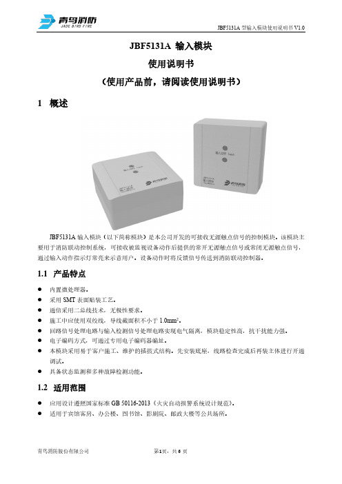
JBF5131A 输入模块使用说明书(使用产品前,请阅读使用说明书)1概述JBF5131A输入模块(以下简称模块)是本公司开发的可接收无源触点信号的控制模块。
该模块主要用于消防联动控制系统,可接收被监视设备动作后提供的常开无源触点信号或常闭无源触点信号,通过输入动作指示灯常亮来示意用户。
设备动作时将反馈信号传送到消防联动控制器。
1.1产品特点⚫内置微处理器。
⚫采用SMT表面贴装工艺。
⚫通信采用二总线技术,无极性要求。
⚫施工中应使用双绞线,导线截面积不小于1.0mm2。
⚫回路信号处理电路与输入检测信号处理电路实现电气隔离,模块稳定性高,抗干扰能力强。
⚫电子编码方式,可通过专用电子编码器编址。
⚫本模块采用易于客户施工、维护的插拔式结构。
先安装底座,线路检查完成后再装主体进行开通调试。
⚫具备状态监测和多种故障检测功能。
1.2适用范围⚫应用设计遵照国家标准GB 50116-2013《火灾自动报警系统设计规范》。
⚫适用于宾馆客房、办公楼、图书馆、影剧院、邮政大楼等公共场所。
1.3型号组成2工作原理模块内嵌微处理器,微处理器实现与消防联动控制器通讯、输入信号状态判断、输入线路故障检测、状态指示灯控制。
模块占用一个编码地址,编址范围1-200。
模块接收被监视设备动作后提供的常开无源触点信号或常闭无源触点信号,点亮“输入动作”指示灯来示意用户,并将反馈信号传送到消防联动控制器。
3性能参数JBF50XX系列控制器、JBF-11SF系列控制器探测特性认证特性消防认证执行标准4 安装调试4.1 安装说明/步骤⚫ 模块采用明装方式。
⚫ 布线施工后,通过预埋盒或使用膨胀螺栓将底座固定在墙上(使用M4螺钉),安装孔距为60mm ,外形及安装尺寸如图1所示。
图1外形及安装尺寸图⚫ 安装之前用电子编码器对其写入相应地址码,此编码应与工程软件中的编码相一致。
⚫ 将总线接在L1、L2端子上,接线无极性。
⚫ 模块端子图例如图2所示:图2端子图◼ L1(端子4)、L2(端子5):接通回路总线,无极性。
GST-8319输入模块安装使用说明书
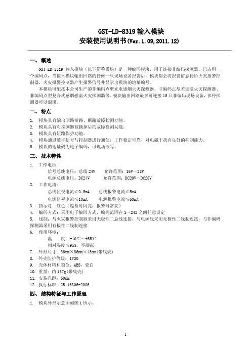
GST-LD-8319输入模块安装使用说明书(Ver.1.09,2011.12)一、概述GST-LD-8319输入模块(以下简称模块)是一种编码模块,用于连接非编码探测器,只占用一个编码点,当接入模块输出回路的任何一只现场设备报警后,模块都会将报警信息传给火灾报警控制器,火灾报警控制器产生报警信号并显示出模块的地址编号。
本模块可配接本公司生产的非编码点型光电感烟火灾探测器、非编码点型差定温火灾探测器、非编码点型复合式感烟感温火灾探测器等。
模块输出回路最多可连接15只非编码现场设备,多种探测器可以混用。
二、特点1.模块具有输出回路短路、断路故障检测功能。
2.模块具有对探测器被摘掉后的故障检测功能。
3.模块具有短路保护功能。
4.模块通过数字信号与控制器进行通信,工作稳定可靠,对电磁干扰有良好的抑制能力。
5.模块的地址码为电子编码,可现场改写。
三、技术特性1.工作电压:信号总线电压:总线24V 允许范围:16V~28V电源总线电压:DC24V 允许范围:DC20V~DC28V2.工作电流:总线监视电流≤0.5mA 总线报警电流≤5mA电源监视电流≤10mA 电源报警电流≤60mA3.指示灯:红色(巡检时闪亮,报警时常亮)4.编码方式:采用电子编码方式,编码范围在1~242之间任意设定5.线制:与火灾报警控制器采用无极性二总线连接,与电源线采用无极性二线制连接,与非编码探测器采用有极性二线制连接6.使用环境:温度:-10℃~+55℃相对湿度≤95%,不凝露7.外形尺寸:86mm×86mm×43mm(带底壳)8.外壳防护等级:IP309.壳体材料和颜色:ABS,瓷白10.重量:约137g(带底壳)11.安装孔距:60mm12.执行标准:GB 16806-2006四、结构特征与工作原理1.模块外形示意图如图1所示。
图1 模块外形示意图2.工作原理模块具有输出回路短路、断路检测功能,输出回路的末端连接终端器,当输出回路断路时,模块将故障信息传送给火灾报警控制器,火灾报警控制器显示出模块的编码地址;当输出回路中有现场设备被取下时,模块会报故障但不影响其它现场设备正常工作。
GE Fanuc RX3i PacSystem 919-535-3180输入模块说明说明书
Rx3i PacSystem919-535-3180*******************GE Fanuc IC694MDL654/automation/ge-fanuc/rx3i-pacsystem/IC694MDL654Input module 5/12 VDC (TTL) 32 point POS/NEG logic. IC694M IC-694MD IC694MDLGFK-2314C Chapter 6 Discrete Input Modules 6-27Input Module, 5/12 VDC (TTL) 32 Point Pos/Neg Logic: IC694MDL654The 5/12VDC (TTL) 32 Point Positive/Negative Logic Inputmodule, IC694MDL654 provides 32 discrete TTL voltage threshold input points. The inputs are arranged in four isolated groups of eight. Each group has its own common. The inputs are positive or negative logic inputs that operate at levels up to 15V.A single, regulated +5V supply (current limited to approximately 150mA) is available through the I/O connectors on the front of the module. This supply is generated on the module and is isolated from the backplane. Its power input comes from the +5V logic supply on the PLC backplane. By installing jumpers on the I/O connector, you can choose to power the inputs from this internal supply instead of powering them with an external user provided supply.This module does not report special fault or alarm diagnostics. Green LEDs indicate the ON/OFF status of each input point. The blue band on the front label shows that MDL654 is a low-voltage module.This module can be installed in any I/O slot in the RX3i system.6-28 PACSystems™ RX3i System Manual – October 2005 GFK-2314CSpecifications: MDL654Rated Voltage5 to 12 volts DC, Positive or Negative Logic Input Voltage Range 0 to 15 volts DCInputs per Module 32 (four groups of eight inputs each)98.4 feet (30 meters), maximum cable lengthMaximum number of inputs per group on at the same time depends on the ambient temperature as shown below. Isolation:Field to Backplane(optical) and to frame ground250 VAC continuous; 1500 VAC for one minuteGroup to Group 50 VAC continuous; 500 VAC for one minute Input Current 3.0mA (typical ON current @ 5VDC)8.5mA (typical ON current @ 12VDC) Input CharacteristicsOn–state Voltage 4.2 to 15 volts DC Off–state Voltage 0 to 2.6 volts DC On–state Current 2.5mA (minimum) Off–state Current 1.2mA (maximum) On response Time 1ms maximum Off response Time1ms maximumInternal Power Consumption195mA (maximum) from +5V bus on backplane; (29mA + 0.5mA/point ON + 4.7mA/LED ON)440mA (maximum) from +5V bus on backplane (if module isolated +5V supply used to power inputs and all 32 inputs ON) 96mA (typical) from user input supply @ 5VDC and 32 inputs ON)272mA (typical) from user input supply @ 12VDC and 32 inputs ON)Isolated +5V Supply +5 volts DC +/-5% Current limit150mA (typical)Refer to Appendix A for product standards and general specifications.Input Points vs. Temperature10°C 20°C 30°C 50°C 60°CNumber of Inputs perAmbient Temperature (°C)40°C8 6 4 2GFK-2314C Chapter 6 Discrete Input Modules 6-29Field Wiring: MDL654The blue band on the label shows that MDL654 is a low-voltage module.Connections are made to two male 24–pin connectors (Fujitsu FCN–365P024–AU) on the frontof the module. Wiring from the connectors to field devices is made through a cable having a mating female connector on one end and stripped and tinned wires on the other end. You can purchase a pair of pre–wired cables, catalog numbers IC693CBL327 and IC693CBL328 or build cables. See Appendix B for more information.Conventional TTL wiring practices should be followed when installing this module. For noise immunity, I/O control lines connected to the module must be less than 30 meters in length (signal attenuation limits wiring length to less than this maximum).Note: If the 24V OUT pin is used to connect to input devices in the field, the isolationspecification for this module changes to: Note: If the 24V OUT pin is used to connect to input devices in the field, the isolation specification for this module changes to:Field to Backplane (optical) and to frame ground : 50 VAC continuous; 500 VAC for 1 minuteTTL WiringTo be compatible with TTL outputs, the negative logic configuration should be used as shown below.。
K-DI01 16通道24VDC数字量输入模块使用说明书
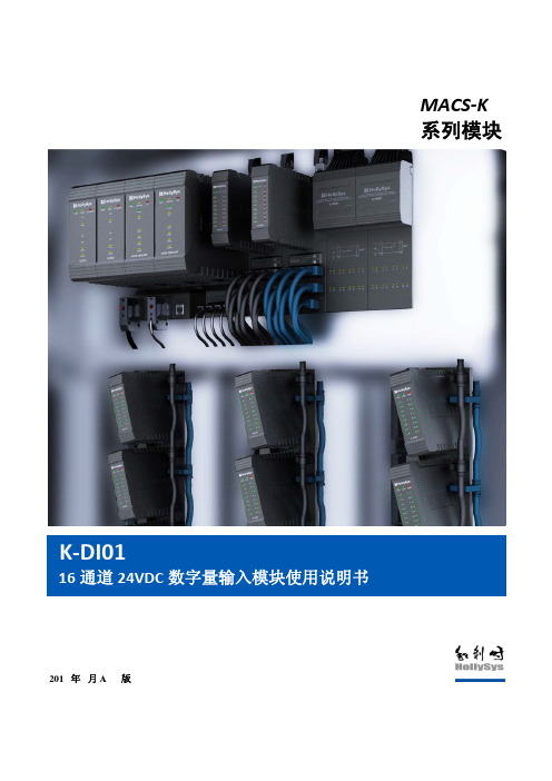
录
1. 概述 .......................................................................................................................................... 1 2. 接口说明...................................................................................................................................... 2 2.1 多功能总线........................................................................................................................ 3 2.2 现场信号接线说明 ............................................................................................................ 5 2.3 模块地址跳线 .................................................................................................................. 12 2.4 模块的防混淆设计 .......................................................................................................... 13 3. 指示灯状态................................................................................................................................ 14 4. 其他特殊功能说明.................................................................................................................... 15 4.1 抗 AC220V 功能 ............................................................................................................. 15 4.2 诊断功能.......................................................................................................................... 16 4.3 冗余功能.......................................................................................................................... 16 5. 工程应用.................................................................................................................................... 17 5.1 底座选型说明 .................................................................................................................. 17 5.2 端子板选型说明 .............................................................................................................. 18 5.3 应用注意事项 .................................................................................................................. 19 6. 性能指标.................................................................................................................................... 19
JSM-M900M输入模块 安装、维护及说明书
Wiring
NOTE: All wiring must conform to applicable local codes, ordinances and regulations.
1. Set the address on the module as the drawing requirements. 2. All the wirings must be in accordance with the job drawing
2
I56-900-03C
Ver.3
Figure 3. JSM-M900M Input Module Wiring Diagram:
JSM-M900M
3.9K EOL RESISTOR
Figure2B. Module Mounting Size:
124.6mm
124.6mm
Note:
Terminal 1(-) and Termianl 2(+) ------------------ COMMMUNICATION LINE Terminal 8 and 9 --------------------------MONITOR INPUT
and the appropriate wiring diagrams (Figure 3). 3. Secure module to electrical box (supplied by installer), as
3 shown in Figure 2A.
Figure 2A. Exploded View of Typical Module detailing Mounting Arrangement
1
I56-900-03C
依爱J-EI6042N输入输出模块说明书V14.0
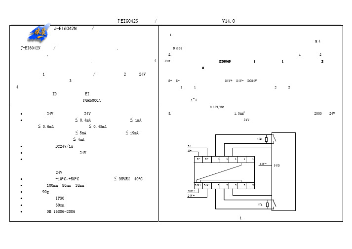
V14.0
47kΩ 无源反馈
半降
S+ SSS+ 返回1 返回1 常开1 公共1 常闭1 DC24V 继电器
有源控制+
有源控制模块底座 卷帘门控制板
模块底座
24V+ 24V- 返回2 返回2 常开2 公共2 常闭2 24V+ 24V47kΩ 全降
址编码标注在平面图对应位置上。使用编码器设置EI6042N模块地址。 2. EI6042N模块接入控制器总线后,利用操作菜单“测试”→“智能部件调试” →“智能部件统计”对 EI6042N模块进行登录,控制器会显示已登录的EI6042N模块出厂编号及地址,如“1113010010 时输入模块的地址设置为出厂编号的最后两位。 3.参见EI系列火灾报警控制器安装使用说明书,根据EI6042N模块的配接设备类型、地址、物理位置等进 行编程。EI6042N模块占用2-4个地址,编程时需要对“实地址”、“虚地址”分别进行编程。编程后EI6042N 模块处于正常监视状态,模块不应报故障或报动作,若编为闪灯方式,则返回1指示灯周期闪亮。。 4. 系统安装调试完毕后应进行模拟火警试验,相应的模块应正确动作,并能正确检测出输入返回端的状 态,输出线故障和24V电源断线的状态。 010”,出厂
J-EI6042N 型输入/输出模块安装使用说明书 J-EI6042N型输入/输出模块
概述 J-EI6042N型输入/输出模块有两组输入和两组输出,其中输入既可以检 测设备的返回信号,也可以检测报警信号。只作为输出模块使用占用两个地 址;若有一个输入作通用输入报警口使用,则还需占用一个地址;最多占用4 个地址。 基本功能(1)接收控制器的命令启动/关闭继电器; (2)检测24V电源 线、输入线和输出线的断路; (3)通过无源常开触点监视外部设备动作情况; (4)线路故障、动作时分别有光指示; 电子编码,唯一 ID 地址,可通过 EI 系列火灾报警控制器、火灾报警控 制器(联动型)在线设置地址或使用 PGM6000A 编码器设置地址。 技术特性 • 工作电压:24V脉动总线电压;24V直流电压。 • 总线工作电流:监视电流 ≤ 0.4mA;输出动作一路增加≤ 1mA;输入 动作一路增加≤ 0.6mA;点亮故障灯增加≤ 0.45mA。 电源工作电流:监视电流 ≤ 5mA;输出动作一路增加≤ 19mA(不含外 接继电器) ;输入动作一路增加 ≤ 4mA。 • 输出触点容量:DC24V/1A。 • 线 制: 四线制,总线及24V电源无极性。 • 输出动作灯:红色,继电器动作时点亮。 输入动作灯:红色,检测到输入动作信号后点亮。 故障灯:黄色,24V电源线、输出线或输入线断路时点亮。 • 使用环境温度:-10°C∼+50°C;使用环境湿度:≤ 95%RH(40°C) 。 • 外形尺寸:100mm×80mm×38mm; • 重量:约90g(不含底座) 。 • 外壳防护等级:IP30 。 • 底座安装孔距:60mm。 • 执行标准:GB 16806-2006 《消防联动控制系统》 。 安装与布线
MINISIM900A模块使用手册

思诺智嵌电子科技苏州有限公司工业级MINISIM900A模块使用说明书该产品:1.可直接内嵌到你的产品2.带音频输入输出接口,利用调试软件可直接拨打接听电话3.该产品分为普通版本和带语音合成的TTS两个版本,您可根据需要选择。
淘宝店铺:模块图片:【1】模块特点:1.本模块上电自启动,无需手动启动。
2.低电压启动,我们的模块只要5V的电源就能稳定的启动并运行,但电流必须大于1A 随后我们会推出与之配套的电源模块。
3.省去大量IO,仅保留最常用的引脚,板子更小更节省空间。
更适合内嵌入您的产品。
更低廉的价格。
4.使用GPRS天线可选配,分专业级和试验级别。
还预留更小的RF小头天线的接口。
方便配合您的产品外壳设计,5.整个模块供电部分有TVS瞬态保护二极管。
防止短路对模块造成的损坏。
SIM卡预留有ESD保护电路,即保护你的SIM卡又保护SIM900A自身的安全。
【2】引脚定义:电源口:+5V GND;通信端口:GND RX TX;控制备用端口:RTC:后备电源接入口IGT:外部信号启动模块,和低功耗应用有关,具体请查阅资料。
RST:模块复位信号输入端,低电平复位。
【3】:模块确认及验证:收到模块后,确认模块完好无损的情况下,1:无SIM卡上电:将5V 1A(以上)电源正负极正确接入模块,观察指示灯:PWR灯长亮;NET灯长亮1秒之后闪烁。
表明模块无异常。
2:断电,将准备好的SIM卡【(移动或联通)请确保该卡无欠费,并能在手机上正常接打电话,收发短信。
】方式SIM卡槽内,注意SIM卡缺口和翻盖式SIM卡座缺口一一对应。
3:串口调试:首先应确保USB TO 232模块在电脑上正确识别。
查看并记下所占用串口(如串口1)波特率默认9600接线:usb to rs232 TX-->miniSIM900A-RXusb to rs232 RX-->miniSIM900A-TX4.打开GSM串口调试助手,如下图所示:苏州思诺智嵌电子科技期待您的光临淘宝店铺:。
- 1、下载文档前请自行甄别文档内容的完整性,平台不提供额外的编辑、内容补充、找答案等附加服务。
- 2、"仅部分预览"的文档,不可在线预览部分如存在完整性等问题,可反馈申请退款(可完整预览的文档不适用该条件!)。
- 3、如文档侵犯您的权益,请联系客服反馈,我们会尽快为您处理(人工客服工作时间:9:00-18:30)。
技术参数
型号 电源 指示灯 功耗 失真度 频率响应 信噪比 通讯协议 通讯接口 重量 DC±12V +5V 工作: ‘W’ ,发送数据: ‘T’ ,接收数据: ‘R’ 2.2W 0.1% 20Hz~20K >80db CAN ISA 0.2kg AL-T5104S
后板介绍
电话输入模块 --- AL-T5104S
产品特点
● ● ● ● ● ● ● ● ● ● 适用于智能矩阵分区、 智能功率分区、 数控网络可寻址广播系统 (BL-C1100E、 D2100E) ; 微电脑控制,抗干扰强; 密码输入操作; 语音提示操作; 具有“学习”忙音功能; 可实现分区、分组、全区电话广播; 话筒输入、线路输出音量可调节; 当有外部电话接入时,具有自动接通功能,外部电话挂断后,能够自动挂断电话; 振铃可设置 2~5 次接通电话; 内置接收数据、发送数据、工作状态等指示灯;