W2 Flat 迷你型光电传感器
德国SICK传感器 PPT课件

电子式 T型槽磁性气缸开关Biblioteka 电子式 T型槽磁性气缸开关
• 使用SICK-ASIC芯片技术 (GMR),具有很高的精度;
• 开关点具有最小的偏差(+/-5%) • 滞后最小(0.7mT+/-0.1mT) • 非常坚固; • 操作简单; • 配置固紧螺丝; • "Drop-in"直接安装方式; • IP67/68/69K防护等级;
近开关
• 具备创新理念的IME接近开关确保您的设备高效, 稳定,具有创新性专用集成算法的ASIC技术以及 内灌以"HOT-MELT"高抗震性材料技术的"肉体", 外套了坚固的镀镍铜"外衣",确保具有高精准检 测精度以及耐高强度震动的冲击
IMF电感式接近开关
IMF电感式接近开关
• 不锈钢外壳(1.4404/316L); • 高防护等级(IP68/IP69K); • 宽温度范围 -40 ℃… +80 ℃(短
G6迷你型电开关
• 采用SICK独创的类激光PinPoint LED光源技术, 光点明亮、精确、清晰
• 提供漫反(300mm)/镜反(7.2m)/对射(15m) 工作方式
• 提供漫反射/镜反射/镜反射透明物体/对射型/对射 灵敏度可调型等
• 大调节旋钮减少安装时间 • 亮通/暗通旋钮设计减少库存型号 • 大而明亮的LED指示灯减少安装维护成本 • 提供套装型号,安装支架和反射镜配套发货,减少
V180-2圆柱形光电开关
V180-2圆柱形光电开关
• 高亮LED红光光源 ,易于对准 • 提供漫反(1100mm)/镜反(7m)/对射
(28m)工作方式 • 提供轴向、径向两种出光方式 ,安装方便灵活 • 提供优异的背景遮蔽功能, 轴向出光1mm ~
奥普士OPTEX普通光电传感器Y系列
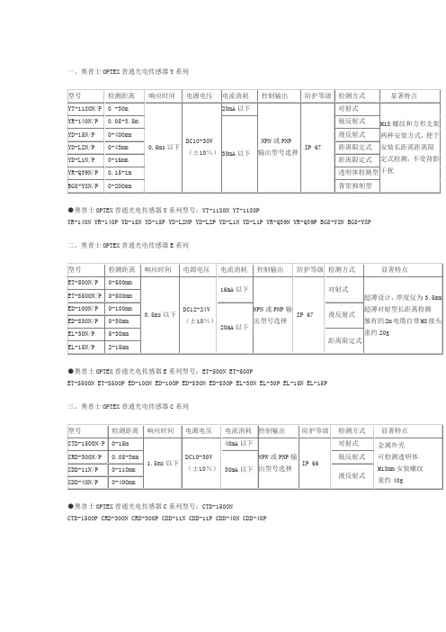
一、奥普士OPTEX普通光电传感器Y系列型号检测距离响应时间电源电压电流消耗控制输出防护等级检测方式显著特点YT-1180N/P 0 -30m0.5ms以下 DC10-30V(±10%)20mA以下NPN或PNP输出型号选择IP 67对射式M18螺纹和方形支架两种安装方式,便于安装长距离距离限定式检测,不受背影干扰YR-140N/P 0.05-3.5m30mA以下镜反射式YD-15N/P 0-400mm 漫反射式YD-L2N/P 0-43mm 距离限定式YD-L1N/P 0-16mm 距离限定式YR-Q39N/P 0.15-1m 透明体检测型BGS-Y8N/P 0-200mm 背景抑制型●奥普士OPTEX普通光电传感器Y系列型号:YT-1180N YT-1180PYR-140N YR-140P YD-15N YD-15P YD-L2NP YD-L2P YD-L1N YD-L1P YR-Q39N YR-Q39P BGS-Y8N BGS-Y8P二、奥普士OPTEX普通光电传感器E系列型号检测距离响应时间电源电压电流消耗控制输出防护等级检测方式显著特点ET-500N/P 0-500mm0.5ms以下 DC12-24V(±10%)16mA以下NPN或PNP输出型号选择IP 67对射式超薄设计,厚度仅为3.5mm超薄对射型长距离检测独有的2m电缆自带M8接头重约20gET-S500N/P 0-500mmED-100N/P 0-100mm20mA以下漫反射式ED-S30N/P 0-30mmEL-30N/P 5-30mm距离限定式EL-15N/P 2-15mm●奥普士OPTEX普通光电传感器E系列型号:ET-500N ET-500PET-S500N ET-S500P ED-100N ED-100P ED-S30N ED-S30P EL-30N EL-30P EL-15N EL-15P三、奥普士OPTEX普通光电传感器C系列型号检测距离响应时间电源电压电流消耗控制输出防护等级检测方式显著特点CTD-1500N/P 0-15m1.5ms以下 DC10-30V(±10%)40mA以下NPN或PNP输出型号选择IP 66对射式金属外壳可检测透明体M18mm安装螺纹重约40gCRD-300N/P 0.05-3mm30mA以下镜反射式CDD-11N/P 0-110mm漫反射式CDD-40N/P 0-400mm●奥普士OPTEX普通光电传感器C系列型号:CTD-1500NCTD-1500P CRD-300N CRD-300P CDD-11N CDD-11P CDD-40N CDD-40P四、施克/奥普士SICK/OPTEX光电传感器J系列型号检测距离响应时间电源电压电流消耗控制输出防护等级检测方式显著特点JT-S/H1000N/P 0-10m0.5 ms以下DC10-30V(±10%) 20mA以下NPN或PNP输出型号选择IP 67对射式内部树脂填充构造,超强的耐水、防油保护超小物体稳定检测(Φ2mm@100mm)超强的抗干扰性JR-S/H300N/P 0-3m 镜反射式JD-S/HR80N/P 0-800mm漫反射式JD-S/HW80N/P 0-80mmJD-S/HL03N/P 20-50mm 距离限定式JR-S/HQ50N/PW 20-500mm 2.5ms/0.5ms 40mA以下透明体检测型●奥普士OPTEX普通光电传感器J系列型号:JT-S1000N JT-S1000P JT- H1000NJT-H1000P JR-S300N JR-S300P JR-H300N JR-H300P JD-SR80N JD-SR80P JD-HR80NJD-HR80P JD-SW80N JD-SW80P JD-HW80N JD-HW80P JD-SL03N JD-SL03P JD-HL03N JD-HL03P JR-SQ50NWJR-SQ50PW JR-HQ50NW JR-HQ50PW五、奥普士OPTEX普通光电传感器J2系列型号检测距离响应时间电源电压电流消耗控制输出防护等级检测方式显著特点J2D-S/H10N/P 5-100mm0.5 ms以下 DC10-30V(±10%) 40mA以下NPN或PNP输出型号选择IP 67漫反射式内部树脂填充构造,超强的耐水、防油保护超小物体稳定检测(Φ2mm@100mm)J2D-S/H100N/P 0-1mJ2D-S/H70N/P 0-700mmBGS-S/H15N/P 50-150mm 2.5ms以下45mA以下背景抑制型●奥普士OPTEX普通光电传感器J2系列型号:J2D-S10N J2D-S10P J2D-H10NJ2D-H10P J2D-S100N J2D-S100P J2D-H100N J2D-H100P J2D-S70N J2D-S70P J2D-H70N J2D-H70P BGS-S15NBGS-S15P BGS-H15N BGS-H15P六、奥普士OPTEX普通光电传感器J3系列型号检测距离响应时间电源电压电流消耗控制输出防护等级检测方式显著特点J3M-GS/H01N/P 8-12mm0.2 ms以下DC10-30V(±10%)40mA以下NPN或PNP输出型号选择IP 67漫反射式内部树脂填充构造,超强的耐水、防油保护超强的抗干扰性J3R-S/H100N/P 0.03-1m 镜反射式BGS-3JS/H05N/P 15-50mm 0.7 ms以下背景抑制型●奥普士OPTEX普通光电传感器J3系列型号:J3M-GS01NJ3M-GS01P J3M-GH01N J3M-GH01P J3R-S100N J3R-S100P J3R-H100N J3R-H100PBGS-3JS05N BGS-3JS05P BGS-3JH05N BGS-3JH05P七、奥普士OPTEX 普通光电传感器K 系列 型号检测距离响应时间 电源电压电流消耗 控制输出 防护等级 检测方式显著特点KT-700N/P 0-7m 1 ms 以下DC10-30V (±10%)35mA 以下NPN 或PNP 输出型号选择IP 67 对射式金属外壳超强防震、抗静电、抗磁场干扰 采用高亮度LED ,超强抗光性 约重25gKR-250N/P 0-2.5m 0.7 ms 以下30mA 以下镜反射式KD-40N/P 0-400mm 漫反射式 KD-L09N/P 10-90mm 距离限定式 KR-Q300N/PW 0-2.5m 透明体检测型 KR-Q150N/PW 0-1.5m 透明体检测型 KR-Q50N/P (W ) 10-500mm透明体检测型●奥普士OPTEX 普通光电传感器K 系列型号:KT-700N KT-700PKR-250N KR-250P KD-40N KD-40P KD-L09N KD-L09P KR-Q300NW KR-Q300PW KR-Q150NW KR-Q150PW KR-Q50N KR-Q50NW KR-Q50P KR-Q50W八、施克/奥普士SICK/OPTEX 普通光电传感器BGS-Z 系列 型号 检测距离 响应时间 电源电压电流消耗 控制输出 防护等级检测方式显著特点BGS-Z10N/P 5-100mm 0.5 ms 以下 DC10-30V (±10%)30mA以下NPN 或PNPIP 67 背景抑制型 达到0.25msBGS-Z30N/P 10-300mm●奥普士OPTEX 普通光电传感器BGS-Z 系列型号:BGS-Z10N BGS-Z10P BGS-Z30N BGS-Z30P九、奥普士OPTEX 普通光电传感器D 系列 型号 检测距离 响应时间 电源电压 电流消耗 控制输出防护等级 检测方式 显著特点DT-4000N/P 0-40m 0.5 ms 以下DC10-30V(±10%)30mA以下NPN 或PNP 输出型号选择IP 67对射式同轴激光光源,安装更方便,定位更精确数位显示,操作更方便具有自动感度调整 约20gDR-500N/P 0-4.5m 镜反射式 DR-Q150TN/P 0-1.5m 0.7 ms 以下 透明体检测型DR-Q400TN/P 0-4m BGS-DL10TN/P 40-100mm 1.5 ms 以下 35mA 以下背景抑制型 BGS-DL25TN/P 100-250mm●奥普士OPTEX 普通光电传感器D 系列型号:DT-4000N DT-4000PDR-500N DR-500P DR-Q150TN DR-Q150TP DR-Q400TN DR-Q400TP BGS-DL10TN BGS-DL10TP BGS-DL25TN BGS-DL25TP十、奥普士OPTEX 普通光电传感器V 系列 型号检测距离响应时间电源电压电流消耗控制输出 防护等级 检测方式显著特点VT-4000(T ) 0-40m 20 ms 以下 DC12-240V 或AC24-240V (±10%)5VA继电器输出IP 67对射式 红色LED 实现,长距离检出 自由选择供给电源 继电器输出或晶体管输出自由选择VR-1000(T ) 0-10m 镜反射式 VD-130(T ) 0-1.3m 漫反射式 VD-300(T ) 0-3m VT-3000N/P 0-30m 1.5 ms 以下DC10-30V (±10%)35mA 以下NPN 或PNP 输出型号选择对射式 VR-800N/P 0-8m 镜反射式 VD-100N/P 0-1m 漫反射式VD-250N/P 0-2.5m●奥普士OPTEX 普通光电传感器V 系列型号:VT-4000 VT-4000TVR-1000 VR-1000T VD-130 VD-130T VD-300 VD-300T VT-3000N VT-3000P VR-800N VR-800P VD-100N VD-100P VD-250N VD-250P十一、施克/奥普士SICK/OPTEX 普通光电传感器V2系列 型号检测距离响应时间 电源电压电流消耗控制 输出防护等级 检测方式 显著特点V2T-2000-3A 0-20m 15 ms 以下 DC12-240V 或AC24-240V (±10%)5VA继电器输出IP 67对射式 红色LED 实现,长距离检出 自由选择供给电源继电器输出或晶体管输出自由选择V2R-800-3A 0-8m 镜反射式BGS-V80 250-800mm 背景抑制型BGS-V50 150-500mm BGS-V30 100-300mm V2T-2000N/P 0-20m 1 ms 以下 DC10-30V (±10%)35mA 以下 NPN 或PNP 输出型号选择对射式V2R-800N/P 0-8m 0.7 ms 以下镜反射式 BGS-V80N/P 250-800mm 3 ms 以下 背景抑制型 BGS-V50N/P 150-500mm 2 ms 以下 BGS-V30N/P 100-300mm BGS-30N/P 100-300mm BGS-10N/P 40-100mm奥普士OPTEX 普通光电传感器V2系列型号:V2T-2000-3AV2R-800-3A BGS-V80 BGS-V50 BGS-V30 V2T-2000N V2T-2000P V2R-800N V2R-800P BGS-V80N BGS-V80P BGS-V50N BGS-V50P BGS-V30N BGS-V30P BGS-30N BGS-30P BGS-10N BGS-10P十二、奥普士OPTEX普通光电传感器V3/V4系列型号检测距离响应时间电源电压电流消耗控制输出防护等级检测方式显著特点V3T-4000 0-40m20ms以下DC12-240V或AC24-240V(±10%)对射式9.5VA;其他5VA继电器输出IP66对射式V3系列电缆式V3R-1000 0-10m 镜反射式V3D-130 0-1.3m 漫反射式V4T-4000 0-40m 对射式V4系列端子式V4R-1000 0-10m 镜反射式V4D-130 0-1.3m 漫反射式●奥普士OPTEX普通光电传感器V3/V4系列型号:V3T-4000V3R-1000 V3D-130V4T-4000 V4R-1000 V4D-130十三、奥普士OPTEX普通光电传感器Z系列型号检测距离响应时间电源电压电流消耗控制输出防护等级检测方式显著特点ZT-1200N/P 0-12m0.5ms以下DC10-30V(±10%)20mA以下NPN或PNP输出型号选择IP67对射式0.5ms以下高速应答最新推出同轴镜面反射型,适应各方面的安装场合适应各种环境抗干扰能力强ZR-350N/P 0-3.5m 镜反射式ZD-70N/P 0-700mm 漫反射式ZD-W20N/P 1-200mm 宽角度漫反射式ZD-L09N/P 10-90mm 距离限定式ZR-Q2000N/P 0.01-2m 透明体检测型ZR-QX200N/P 0-2m 同轴透明体检测型ZR-X250N/P 0-2.5m 0.25ms以下同轴镜反射式●奥普士OPTEX普通光电传感器Z系列型号:ZT-1200N ZT-1200PZR-350N ZR-350P ZD-70N ZD-70P ZD-W20N ZD-W20P ZD-L09N ZD-L09P ZR-Q2000N ZR-Q2000P ZR-QX200N ZR-QX200P ZR-X250N ZR-X250P十四、施克/奥普士SICK/OPTEX普通光电传感器ZL系列型号检测距离响应时间电源电压电流消耗控制输出防护等级检测方式显著特点ZT-L3000N/P 0-30m0.25ms以下DC10-30V(±10%)30mA以下NPN或PNP输出型号选择IP67对射式激光光源,光斑小体积小响应时间快,可达到0.25msZR-L1000N/P 0.08-10m 镜反射式ZD-L40N/P 0-400mm 漫反射式BGS-ZL30N/P 100-300mm背景抑制型BGS-ZL10N/P 5-100mm奥普士OPTEX普通光电传感器ZL系列型号:ZT-L3000NZT-L3000P ZR-L1000N ZR-L1000P ZD-L40N ZD-L40P BGS-ZL30N BGS-ZL30P BGS-ZL10NBGS-ZL10P十五、奥普士OPTEX普通光电传感器Z2系列型号检测距离响应时间电源电压电流消耗控制输出防护等级检测方式显著特点Z2T-2000N/P 0-25m0.5ms以下DC10-30V(±10%)15mA以下NPN或PNP输出型号选择IP67对射式0.5ms以下高速应答最新推出同轴镜面反射型Z2R-400N/P 0.01-4.4m 镜反射式Z2D-80N/P 0-1m 漫反射式奥普士OPTEX普通光电传感器Z2系列型号:Z2T-2000N Z2T-2000P Z2R-400NZ2R-400P Z2D-80N Z2D-80P十六、奥普士OPTEX普通光电传感器Z-M系列型号检测距离响应时间电源电压电流消耗控制输出防护等级检测方式显著特点ZT-M3000N/P 0-30m0.5ms以下DC10-30V(±10%)15mA以下NPN或PNP输出型号选择IP69K对射式耐高温高水压适合生肉生鲜食品IP系数69KZR-M550N/P 0.01-5.5m18mA以下镜反射式ZD-M80N/P 0-800mm 漫反射式BGS-ZM10N/P 20-100mm28mA以下背景抑制型BGS-ZM30N/P 20-300mm●奥普士OPTEX普通光电传感器Z-M系列型号:ZT-M3000NZT-M3000P ZR-M550N ZR-M550P ZD-M80N ZD-M80P BGS-ZM10N BGS-ZM10P BGS-ZM30N BGS-ZM30P十七、奥普士OPTEX 普通光电传感器S 系列 型号检测距离响应时间电源电压电流消耗控制输出防护等级 检测方式 显著特点ST-400N/P 0-4m 0.5ms 以下DC10-30V (±10%)30mA 以下NPN 或PNP 输出型号选择IP67对射式 达到CE 标准的最小体积 0.5ms 以下高速应答重约5g SR-150N/P0-1.5m20mA 以下镜反射式SD-20N/P0-200mm漫反射式BGS-S08N/P 10-80mm背景抑制型 SR-Q50N/PW 10-500mm透明体检测型●奥普士OPTEX 普通光电传感器S 系列型号:ST-400N ST-400PSR-150N SR-150P SD-20N SD-20P BGS-S08N BGS-S08P SR-Q50N SR-Q50PW十八、奥普士OPTEX 普通光电传感器C2系列 型号 检测距离 响应时间电源电压电流消耗控制输出 防护等级检测方式 显著特点 C2TP-2000N/P 0-20m 0.5ms 以下DC10-30V (±10%)20mA 以下 NPN 或PNP输出型号选择IP67对射式 塑料外壳 可检测透明体M18mm 安装螺纹重约40g C2RP-F400N/P 0.01-4m 镜反射式C2RP-350N/P 0.01-3.5m C2DP-11N/P 0-110mm 漫反射式 C2DP-40N/P 0-400mm C2DP-80N/P 0-800mm C2TM-2000N/P 0-20m 对射式 金属外壳 可检测透明体M18mm 安装螺纹重约40gC2RM-F400N/P 0.01-4m 镜反射式C2RM-350N/P 0.01-3.5m C2DM-11N/P 0-110m 漫反射式 C2DM-40N/P 0-400mm C2DM-80N/P 0-800mm奥普士OPTEX 普通光电传感器C2系列型号:C2TP-2000N C2TP-2000PC2RP-F400N C2RP-F400P C2RP-350N C2RP-350P C2DP-11N C2DP-11P C2DP-40N C2DP-40P C2DP-80N C2DP-80P C2TM-2000N C2TM-2000P C2RM-F400N C2RM-F400P C2RM-350N C2RM-350P C2DM-11N C2DM-11P C2DM-40N C2DM-40P C2DM-80N C2DM-80P十九、奥普士OPTEX普通光电传感器S2系列型号检测距离响应时间电源电压电流消耗控制输出防护等级检测方式显著特点S2T-1200N/P 0-12m1.5ms以下DC10-30V(±10%)20mA以下NPN或PNP输出型号选择IP67对射式实现小体积长距离检出0.5ms以下高速应答防水构造重约5gS2R-350N/P 0.01-3.5m 镜反射式S2D-80N/P 0-800mm 漫反射式BGS-2S15N/P 25-150mm30mA以下背景抑制型BGS-2S30N/P 25-300mm●奥普士OPTEX普通光电传感器S2系列型号:S2T-1200N S2T-1200P S2R-350NS2R-350P S2D-80N S2D-80P BGS-2S15N BGS-2S15P BGS-2S30N BGS-2S30P二十、奥普士OPTEX光电传感器V2new系列型号检测距离响应时间电源电压电流消耗控制输出防护等级检测方式显著特点V2T-7000DN/P 0-70m 1ms以下晶体管DC10-30V(±10%)35mA以下NPN或PNP输出型号选择IP67对射式红色LED实现长距离检出自由选择供给电源继电器输出或晶体管输出自由选择V2R-1500DN/P 0-15m 0.7ms以下镜反射式BGS-2V30N/P 10-30mm2ms以下背景抑制型BGS-2V50N/P 15-50mmBGS-2V100N/P 30-100mmV2T-7000(H)0-70m 1ms以下DC12-240V或AC24-240V (±10%)对射式9.5VA;其他5VA继电器输出对射式V2R-1500(H)0-15m 0.7ms以下镜反射式BGS-2V30(H)10-30mm2ms以下背景抑制型BGS-2V50(H)15-50mmBGS-2V100(H)30-100mm●奥普士OPTEX普通光电传感器V2new系列型号:V2T-7000DN V2T-7000DPV2R-1500DN V2R-1500DP BGS-2V30N BGS-2V30P BGS-2V50N BGS-2V50P BGS-2V100N BGS-2V100P V2T-7000 V2T-7000H V2R-1500 V2R-1500H BGS-2V30 BGS-2V30H BGS-2V50 BGS-2V50H BGS-2V100 BGS-2V100H二十一、奥普士OPTEX 位移传感器CD5系列 型号 检测距离测量范围电源电压电流消耗光源防护等级检测方式 显著特点CD5-L25 25mm ±1mmDC12-240V (±10%)或来自控制器红色激光二极管IP 67镜面反射高灵敏度的线性图像传感器 低象差镜头 高速处理单元 宽光点型 预防串扰 3个传感器的多重运算 CD5-LW25 CD5-30 30mm±5mm漫反射 CD5-W30 CD5-85 85mm ±20mm CD5-W85 CD5-W350 350mm ±100mm CD5-W500 500mm ±200mm CD5-W2000 2000mm ±500mm CD5A-N350mA/24VIP 20CD5A-P奥普士OPTEX 位移传感器CD5系列型号:CD5-L25 CD5-LW25 CD5-30 CD5-W30 CD5-85 CD5-W85 CD5-W350 CD5-W500 CD5-W2000 CD5A-N CD5A-P二十二、施克/奥普士SICK/OPTEX 位移传感器CD4/CD1/CD3/CD33系列 型号 测量范围 线性精度电源电压分辨率 最小光斑 显著特点CD4-L25(J) 25±1mm ±0.1%F.S.专用处理器供电0.1μm 约25×35μm不同反射程度的材质表面的稳定检测可见小光点激光光束 具备1个放大器2个传感器头稳定的红、黄、绿功能输出指示灯4个模拟量5个开关量输出 通过RS232与PC 连接可实时观测测量数据 CD4-L30(J) 30±5mm1μm约30×100μmCD4-L30(J)-3R CD4-L85(J) 85±20mm3μm约70×290μmCD4-L85(J)-3R CD4-L350(J) 350±100mm 40μm 约300×700μm CD4-L350(J)-3R CD4A-N DC12-24V (±10%)CD4A-P CD4A-LN CD4A-LP CD1-30N 30±4mm ±2%F.S. 3μm Φ0.5mm 采用PSD 感光元件,操作简单CD1-100N 100±35mm ±2%F.S. 50μm 1×1.5mm CD1-250N 250±150mm ±5%F.S. 500μm 1.5×3mm CD3-30N 30±4mm ±1%F.S. 4μm Φ0.5mm CCD 感光元件,可稳定检测黑色物体,带数字显面板 CD3-100N 100±40mm ±12%F.S.30μm 1×1.5mm CD3-250N 250±150mm±1.5%F.S.150μm1.5×3mm奥普士OPTEX 位移传传感器CD4系列型号:CD4-L25(J) CD4-L30(J) CD4-L30(J)-3R CD4-L85(J) CD4-L85(J)-3R CD4-L350(J)CD4-L350(J)-3R CD4A-N CD4A-P CD4A-LN CD4A-LP CD1-30N CD1-100N CD1-250N CD3-30N CD3-100N CD3-250N二十三、施克/奥普士SICK/OPTEX 位移传感器CD33系列 型号检测距离 测量范围 分辨率 线性度 检测方式检测项目 显著特点CD33-L30N-422 26.3±2mm 1μm 正反射型数字子像素处理 电压和电流输出易选型测量范围的2通道输出可独立设置 高分辨率电子快门 简易操作 CD33-L50N-422 47.3±5mm2.5μmCD33-L85N-42282.9±10mm 5μmCD33-30NV(PV) 30mm30±4mm4μm±0.1%F.S距离型PC 版的翘曲/下垂检测 CD33-30NA(PA) CD33-50NV(PV)50mm50±10mm8μm电路板上零件高度检测 CD33-50NA(PA)CD33-85NV(PV) 85mm85±20mm15μm橡胶板的联合处检测 CD33-85NA(PA) CD33-120NV(PV) 120mm120±60mm45μm橡胶板的松散检测CD33-120NA(PA)奥普士OPTEX 位移传感器CD33系列型号:CD33-L30N-422 CD33-L50N-422CD33-L85N-422 CD33-30NV CD33-30PV CD33-30NA CD33-30PA CD33-50NV CD33-50PV CD33-50NA CD33-50PA CD33-85NV CD33-85PV D33-85NA CD33-85PA CD33-120NV CD33-120PV D33-120NA CD33-120PA二十五、施克/奥普士SICK/OPTEX 色标传感器系列 型号 检测范围 检测方式 显著特点DM-18T 18+/-2mm 采用RGB 三色光源,颜色分辨更细致,而且三色光源可切换 J3M-GH01N 10+/-2mm 采用业界最小的高亮度绿色LED ,投光4阶段调整,安定检出 树脂充填设计,高防护等级,耐水抗油性强J3M-GS01N RT-1500 1.5m 对射型请根据检测要求,选择任意一种检测头与RSA 放大器搭配使用RT-F300 300mm RD-150 150mm 漫反射型RD-F50 50mm RS-20R 20+/-2mm RS-16G 16+/-1mm RM-16R 16+/-2mm RM-16G 16+/-1mm奥普士OPTEX 色标传感器系列型号:DM-18T J3M-GH01NJ3M-GS01N RT-1500 RT-F300 RD-150 RD-F50 RS20R RS-16G RM-16R RM-16G二十四、奥普士OPTEX 放大器分离型激光传感器系列 型号检测距离 光斑电源电压 指示灯防护等级 显著特点DSR-800Long 模式:0-8mStandard 模式:0-5mFast 模式:0-2m Φ2mm/距离2m激光发射指示灯:绿色LED 输出指示灯:橙色LEDIP67高精度8位数显同轴激光放大器分离型光电传感器可进行点、线、面的检测(光束可自行选择) 70M 超远距离检测 Φ1mm 的最小光点双信道独立输出,独立模拟量输出(4-20mA )放大器可扩展50PCS ,可省配线,还可与D2RF 、B2RF 连接以省配线 自带计数功能60μs 高速响应,延时可设定1ms-9sDSR-5000Long 模式:0.5-50mStandard 模式:0.3-35m Fast 模式:0.1-20m Φ2mm/距离2mDSD-100Long 模式:1m Standard 模式:0.7m Fast 模式:0.25mΦ1mm/距离1mDSTC-200 2mΦ2mm/距离2mIP50DSTC-200- M8 DSTA-200 2m 30*2.5mm/距离2m DSTA-200-M8D2SA-MNS DC12-24V (10%)激光发射指示灯:绿色 输出指示灯:橙色D2SA-MN D2SA-SN D2SA-MN3S D2SA-MNS-M8 D2SA-MN3S D2SA-MN3S-M8 D2SA-SN1 D2SA-SN-M8奥普士OPTEX 放大器分离型激光传感器系列型号:DSR-800DSR-5000 DSD-100 DSTC-200- M8 DSTA-200 DSTA-200-M8 D2SA-MNS D2SA-MN D2SA-SN D2SA-MN3S D2SA-MNS-M8 D2SA-MN3S D2SA-MN3S-M8 D2SA-SN1 D2SA-SN-M8二十六、奥普士OPTEX 放大器分离式光纤传感器系列 型号 控制输出电源电压光源消耗电流种类防护等级显著特点D2RF-TN 2CH 输出:CH1:NPN 或PNP 输出CH2:报警输出或外部输入DC12-24V (±10%)红色LED24V 时,45mA 以下单独型IP50双数显两种状态,八位数字对比显示 独立的两信道输出功能60μS 快速响应速度 功能强大的ASC/APC 自动调节功能,不受苛刻恶劣环境影响 多种检测模式适用于各种检测物D2RF-TCN4 D2RF-TMN 连接型主机D2RF-TMCN4 D2RF-TSN 连接型子机D2RF-TSCN4 D2GF-TN 绿色LED单独型D2GF-TCN4 D2GF-TMN 连接型主机D2GF-TMCN4 D2GF-TSN 连接型子机 D2GF-TSCN4 D2RF-TAN NPN 输出或PNP 输出 红色LED 单独型模拟量输出型 NF-DB01 最宽的显示屏 更简单的操作 更直观的辨认显示数值超远感应距离NF-DR01 NF-DH01 NF-TB01 NF-TR01 NF-TH01D3RF-TN NPN 输出DC12-24V (±10%)红色LED正常模式:DC24V 时,1信道输出36mA ,2信道输出39mA 省电模式: DC24V 时,1信道输出25mA ,2信道输出28mA个体式IP50 D3RF-TDN D3RF-TMN 分体式-主机 D3RF-TDMN D3RF-TSN 分体式-副机D3RF-TDSNVRF-N(P) NPN 或PNP 输出 DC10-30V (±10%)红色LED单独型:12V 时,25mA 以下 连接型: 12V 时, 35mA 以下标准型IP6610圈灵敏度调整,灵敏度更线性化 独特的光纤插入到位指引,设计更人性化 BIF 独特的水分检测功能VRF-CN(P) VRF-HN(P) 高速应答型 VRF-HCN(P) JRF-N(P) 防水型JRF-CN(P) BRF-N(P) 标准型 B2RF-N(P) BRF-CN(P)B2RF-CN(P) BRF-HN(P) 高速应答型B2RF-HN(P) BRF-CHN(P) B2RF-CHN(P) BGF-N(P) 绿色LED色标检测型 B2GF-N(P) BGF-CN(P) B2GF-CN(P) BIF-N(P) 红色LED水分检测型B2IF-N(P) BIF-CN(P) B2IF-CN(P) NF-DR06 NF-TS12 NF-DT01 NF-TS14 NF-DV01 NF-TY01 NF-TS24 NF-TH05S NF-TS22M NF-DC02奥普士OPTEX 放大器分离式光纤传感器系列型号:D2RF-TN D2RF-TCN4 D2RF-TMN D2RF-TMCN4 D2RF-TSN D2RF-TSCN4 D2GF-TN D2GF-TCN4 D2GF-TMN D2GF-TMCN4 D2GF-TSN D2GF-TSCN4 D2RF-TAN NF-DB01 NF-DR01 NF-DH01 NF-TB01 NF-TR01 NF-TH01 D3RF-TN D3RF-TDN D3RF-TMN D3RF-TDMN D3RF-TSN D3RF-TDSN VRF-N VRF-P VRF-CN VRF-CP VRF-HN VRF-HP VRF-HCN VRF-HCP JRF-N JRF-P JRF-CN JRF-CP BRF-N BRF-P B2RF-N B2RF-P BRF-CN BRF-CP B2RF-CN B2RF-CP BRF-HN BRF-HP B2RF-HN B2RF-HP BRF-CHN BRF-CHP B2RF-CHN B2RF-CHP BGF-N BGF-P B2GF-N B2GF-P BGF-CN BGF-CP B2GF-CN B2GF-CP BIF-N BIF-P B2IF-N B2IF-P BIF-CN BIF-CP B2IF-CN B2IF-CP NF-DR06 NF-TS12 NF-DT01 NF-TS14 NF-DV01 NF-TY01 NF-TS24 NF-TH05S NF-TS22M NF-DC02二十七、奥普士OPTEX图像传感器系列型号摄影角度焦点距离摄影面积消耗电流电源电压防护等级检测方式显著特点CVS1-N10-R 10度210-270mm 40×50-55×65mm最大120mA/24VDC DC12-24V(±10%)IP67长距离检测型体积小安装方便对色面积能广泛检测CVS1-N20-R 20度90-150mm 40×50-65×75mm 标准检测型CVS1-N40-R 40度50-100mm 50×65-100×115mm 近距离宽角度检测型CVS2-N10-R 10度210-270mm 40×50-55×65mm 长距离检测型CVS2-N20-R 20度90-150mm 40×50-65×75mm 标准检测型CVS2-N40-R 40度50-100mm 50×65-100×115mm 近距离宽角度检测型CVS3-N20-R20度90-150mm 40×50-65×75mm标准检测型CVS3-N21-R 35+/-4mm 17×20mm 狭视界检测型CVS4-N20-R20度90-150mm 53×25-79×38mmCVS4-N21-R 35+/-4mm 21×10mmCVS4-N23-R50+/-6mm 30×15mmCVS4-N23R-RMVS-PM 最大10mA/24VDC DC6±10%IP50 MVS-DN最大80 mA/24VDC DC24±10%IP20 MVS-DP奥普士OPTEX图像传感器系列型号:CVS1-N10-R CVS1-N20-R CVS1-N40-R CVS2-N10-R CVS2-N20-R CVS2-N40-R CVS3-N20-R CVS3-N21-R CVS4-N20-R CVS4-N21-R CVS4-N23-R CVS4-N23R-R MVS-PM MVS-DN MVS-DP二十八、奥普士OPTEX形状识别传感器系列型号检测范围受光范围电源电压电流消耗光源防护等级显著特点SHP-100CN 100±25mm 宽17mm/距离75mm宽27mm/距离125mmDC12-24V(±10%)120mA 0.3mm×32mm IP50长距离、宽范围、超高速取样、高精度测量同时具备3个开关量和1个模拟量输出奥普士OPTEX形状识别传感器系列型号:SHP-100CN 二十九、奥普士OPTEX视觉传感器系列型号CPU SDRAM FLASH ROM 输出图像绝缘型I/O电源显著特点TA-3000系列TI DSP TMS320DM642:720MHz 128MB 133MHz 4MB NTSC or VGA每个16点DC+24V软件包:TA硬件:高速图像处理系统TA-3100系列VGA DC+12V (AC/DC 电源转接器)TA-4610系列TI DSP TMS320DM642:720MHzDSP组件盘:最多可以搭配8个128MB(每个DSP组件盘)8MB VGA每个8点(MAX:32点)AC100-240(有关闭开关)。
G6迷你型光电传感器选型手册(中文版)
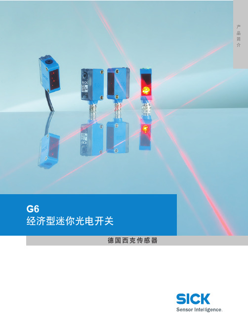
G6经济型迷你光电开关德国西克传感器产品简介2 S I C K超越标准 - G6易于对准经济型迷你光电开关3w w w.s i c k.c o m/g lo b al s en so r片技术S I C K4 S I C KGTB6L+M QL+MQ NC漫反射式光电开关,背景遮蔽型LED光源技术,光点更亮更精确 金属螺纹安装孔,安装简便且坚固 大旋钮方便调节 指示灯大而明亮类激光性能施克 芯片,抗环境干扰和传感器互相干扰ASIC 光轴接收光轴发射所有尺寸均为毫米(英寸)G6S I C K5252010501550(1.97)mm(inch)100(3.94)150(5.91)200(7.87)250(9.84)300(11.81)Ø 6.6Ø 5.6Ø 5.3(5.91)(9.84)(1.97)(7.87)(3.94)(11.81)18 % 90 %2 6 %311)对90%反射率物体(基于DIN 5033的标准白色)2) T a=+25°C下平均工作时间100,000小时3)限定值,电源极性反接在短路保护下电流最大8A4) 不可以超出供电电压Vs允许范围值信号冗余最大典型检测范围检测距离对白色( 的反射率)的检测距离对灰色( 的反射率)的检测距离对黑色( 的反射率)的检测距离5) 空载8) 0°C以下不可弯曲6)电阻性负载情况下信号传输时间7) 亮/暗比例1:1所有尺寸均为毫米(英寸)距离单位为毫米(英寸)距离单位为毫米(英寸)6 S I C KL+M Q所有尺寸均为毫米(英寸)LED光源技术,光点更亮更精确 金属螺纹安装孔,安装简便且坚固施克ASIC芯片,抗环境光干扰和传感器互相干扰 大旋钮方便调节 指示灯大而明亮光轴接收光轴发射L+M Q NC反射式光电开关,增强型漫类激光性能GTE6G6S I C K 71)对90%反射率物体(基于DIN 5033的标准白色)2) T a=+25°C下平均工作时间100,000小时3)限定值,电源极性反接在短路保护下电流最大8A4) 不可以超出供电电压Vs允许范围值检测范围1000101信号冗余mm(inch)50(1.9)100(3.9)150(5.9)200(7.9)250(9.8)300(11.8)215) 空载8) 0°C以下不可弯曲6)电阻性负载情况下信号传输时间7) 亮/暗比例1:1最大典型检测距离距离[mm]8 S I C KGL6镜反射式光电开关金属螺纹安装孔,安装简便且坚固 施克ASIC芯片,抗环境光干扰和传感器互相干扰 大旋钮方便调节指示灯大而明亮L+M Q所有尺寸均为毫米(英寸)L+M Q NC光轴接收光轴发射M3螺纹安装孔LED光源技术,光点更亮更精确G6S I C K 9(inch)(78.7)(157.5)(236.2)(315.0)1) Ta=+25°C下平均工作时间100,000小时2)限定值,电源极性反接在短路保护下电流最大8A 3) 不可以超出供电电压Vs允许范围值4)空载5) 电阻性负载情况下信号传输时间6) 亮/暗比例1:17) 0°C以下不可弯曲检测范围 (EGR: 2)[m]GL6镜反射式光电开关,可调节灵敏度检测距离 6 m镜反射式光电开关尺寸图所有型号调节+–4针,M81L+M Q34棕色蓝色黑色3 x 0.14 mm 2连接类型GL6-P4211GL6-N4211GL6-P1211GL6-P1212GL6-N1211GL6-N1212附件电缆和接头安装附件反射镜所有尺寸均为毫米(英寸)1L+M Q NC342棕色蓝色黑色白色光轴接收器光轴发射器M3螺纹安装孔绿色LED 指示灯,电源黄色LED 指示灯,接收光线亮通/暗通旋钮: L = 亮通D = 暗通接收器灵敏度调节器①②③④⑤⑥⑦PinPoint LED 光源技术,光点更亮更精确金属螺纹安装孔,安装简便且坚固SICK ASIC 芯片,抗环境光干扰和传感器互相干扰可通过270°电位计调节接收器灵敏度适用于特殊表面和光亮物体7.6(0.30)9.7(0.38)18.3(0.72)21 (0.83)11.4(0.45)31.5 (1.24)28.5 (1.12)25.4 (1.00)0.5 (0.02)0.5 (0.02)9.7(0.38)3 (0.12)L D12(0.47)S I C K10G6S I C K 11信号冗余Ø 8 mmØ 25 mmØ 80 mmØ 130 mm距离(米)传感器3.05.01.00.351)TA = +25°C 时,平均工作时间100000小时2) 限定值,短路保护下的最大电流为8 A 3)不得超出供电电压V S 的允许范围值4) 空载5)V S > 24 V 或环境温度大于49 °C 时,最大电流I A = 50 mA6) 电阻负载下的信号传输时间7) 亮/暗比例为1:18) 低于0 °C 时不可弯曲最大检测距离6 m 检测范围 5 m接收器灵敏度调节器270°电位计配套装置 PL80A 反射镜光源类型LED 红光,650 nm 1) 光点直径8 mm ,距离350 mm 处偏光滤镜 供电电压V S 10 ... 30 V DC 2)残余纹波 ± 10 % 3) 能耗 ≤ 30 mA 4)开关输出 NPN :集电极开路:QPNP: QPNP 高/低输出电压V S – (≤ 3 V)/约0 V NPN 高/低输出电压约V S /≤ 3 V 输出方式 亮通/暗通旋钮最大输出电流I A 100 mA 5)响应时间 < 625 µs 6)切换频率典型值为1 kHz 7)连接方式电缆,PVC ,2 m 8)M8接头,4针防护等级电流保护电源极性反接保护输入输出短路保护输出过流保护防护等级IP 67环境温度工作温度 –25 °C ... +55 °C储存温度 –40 °C ... +70 °C 重量 M8接头型,约20 g2 m 电缆型,约60 g 外壳材质ABS, PC, PMMA随附配件P250反射镜,安装支架N1211技术数据GL6-N1212N4211P1211P1212P4211检测距离和信号冗余型号Part no.GL6-P1211GL6-P1212GL6-P4211GL6-N1211GL6-N1212GL6-N4211105992210608151059241105992310608141059631订货信息REF-IRF-56型反射镜PL20A 型反射镜P250型反射镜PL40A 型反射镜PL80A 型反射镜反射镜型号 检测范围0.25 ... 1.6 m0.07 ... 2.2 m 0.07 ... 3.5m 0.07 ... 3.8 m 0.07 ... 5.0 m 订货号检测范围最大检测距离距离单位为米(英寸)距离单位为米(英寸)最大检测距离检测范围12GL6G 镜反射式光电开关检测距离6 m镜反射式光电开关尺寸图所有型号调节4针,M81L+M Q34棕色蓝色黑色3 x 0.14 mm 2连接类型GL6G-P4211GL6G-P4212GL6G-N4211GL6G-N4212GL6G-P1211GL6G-P1212GL6G-N1211GL6G-N1212附件电缆和接头安装附件反射镜7.6(0.30)9.7(0.38)18.3(0.72)21 (0.83)11.4(0.45)31.5 (1.24)28.5 (1.12)25.4 (1.00)0.5 (0.02)0.5 (0.02)9.7(0.38)3 (0.12)L D12(0.47)所有尺寸均为毫米(英寸)1L+M Q NC342棕色蓝色黑色白色光轴接收器光轴发射器M3螺纹安装孔绿色LED 指示灯,电源黄色LED 指示灯,接收光线亮通/暗通旋钮: L = 亮通D = 暗通接收器灵敏度调节器+–PinPoint LED 光源技术,光点更亮更精确金属螺纹安装孔,安装简便且坚固SICK ASIC 芯片,抗环境光干扰和传感器互相干扰可通过270°电位计调节接收器灵敏度适用于特殊表面和光亮物体①②③④⑤⑥⑦S I C KG6S I C K 13信号冗余Ø 8 mmØ 25 mmØ 80 mmØ 130 mm距离(米)3.05.01.00.351)T A = +25 °C 时,平均工作时间100000小时2) 限定值,短路保护下的最大电流为8 A 3) 不得超出供电电压V S 的允许范围值4) 空载5)最小光束衰减为20%6) V S > 24 V 或环境温度大于49 °C 时,最大电流I A = 50 mA7) 电阻负载下的信号传输时间8) 亮/暗比例为1:19)低于0 °C 时不可弯曲10) 温度需稳定在±10 °C 范围内最大检测距离 6 m 检测范围 5 m接收器灵敏度调节器270°电位计配套装置 PL80A 反射镜光源类型 LED 红光,650 nm 1) 光点直径 8 mm ,距离350 mm 偏光滤镜 供电电压V S 10 ... 30 V DC 2)残余纹波 ± 10 % 3)能耗 ≤ 30 mA 4)开关输出 NPN :集电极开路:QPNP: Q 光束衰减 > 20%特殊设计 适用于透明物体 5)PNP 高/低输出电压V S – (≤ 3 V)/约0 V NPN 高/低输出电压约V S /≤ 3 V 输出方式 亮通/暗通旋钮最大输出电流I A 100 mA 6)响应时间 < 625 µs 7)切换频率典型值为1 kHz 8) 连接方式电缆,PVC ,2 m 9)M8接头,4针防护等级电流保护电源极性反接保护输入输出短路保护输出过流保护防护等级IP 67环境温度T A 工作温度 –25 °C ... +55 °C 10)储存温度 –40 °C ... +70 °C 重量 M8接头型,约20 g2 m 电缆型,约60 g 外壳材质ABS, PC, PMMA随附配件P250反射镜,安装支架N1211技术数据GL6G-N1212N4211N4212P1211P1212P4211P4212检测距离和信号冗余型号订货号GL6G-P1211GL6G-P1212GL6G-P4211GL6G-P4212GL6G-N1211GL6G-N1212GL6G-N4211GL6G-N421210599241060812105963210608101059925106081110596331060809订货信息REF-IRF-56型反射镜PL20A 型反射镜P250型反射镜PL40A 型反射镜PL80A 型反射镜反射镜型号 检测范围0.25 ... 1.6 m0.07 ... 2.2 m 0.07 ... 3.5m 0.07 ... 3.8 m 0.07 ... 5.0 m检测范围最大检测距离距离单位为米(英寸)距离单位为米(英寸)最大检测距离检测范围传感器S I C KL+M QL+MQ NC射式光电开关对 LED光源技术,光点更亮更精确 金属螺纹安装孔,安装简便且坚固 大旋钮方便调节 指示灯大而明亮类激光性能光轴接收光轴发射所有尺寸均为毫米(英寸)GSE610G6S I C K 111,000100101(inch)(157.48)(472.44)(314.96)(629.92)[m]信号冗余检测范围1) Ta=+25°C下平均工作时间100,000小时2)限定值,电源极性反接在短路保护下电流最大8A 3) 不可以超出供电电压Vs允许范围值4)空载5) 电阻性负载情况下信号传输时间6) 亮/暗比例1:17) 0°C以下不可弯曲最大典型检测距离距离电缆和插头/安装附件Ø9.8(.4)8.2Ø9.81)使用过程中最小弯曲半径R min = 20 x 电缆直径所有尺寸均为毫米(英寸)所有尺寸均为毫米(英寸)所有尺寸均为毫米(英寸)所有尺寸均为毫米(英寸)Ø9.8(.4)8.2Ø9.81)使用过程中最小弯曲半径R min = 20 x 电缆直径12S I C KS I C K13附件L1412All dimensions in mm (inch)所有尺寸均为毫米(英寸)所有尺寸均为毫米(英寸)锁紧螺丝反射镜14 S I C K1)发货包含 GL6 标准型号S I C K15附件完善的服务领先的技术独特的产品SICK 概览SICK CHINA| 客户服务专线: 4000-121-0008014182/2013-09-09中文译本 内容如有变更,恕不另行通知SICK 是一家世界顶级的传感器技术提供商,在全球建立了接近50个子公司和众多的销售机构, 雇员总数超过6,300人。
莱纳尔工程公司产品说明书:微型自包含光电传感器安装指南

Install GuideMiniature self-contained photoelectric sensors in universal-mount housingFor complete technical information about this product, including dimensions, accessories, and specifications, see and search 63908.WARNING: Not To Be Used for Personnel ProtectionNever use this device as a sensing device for personnel protection. Doing so could lead to serious injury or death. This device does not include the self-checking redundant circuitry necessary to allow its use in personnel safety applications. A sensor failure or malfunction can cause either an energized or de-energized sensor output condition.ModelsQD Models:4-pin integral Euro-style QD: add suffix Q8, for example, QS186EQ8.4-pin 150 mm (6 in) Euro-style pigtail QD: add suffix Q5, for example,QS186EQ5.4-pin integral Pico-style pigtail QD: add suffix Q7, for example,QS186EQ7).4-pin 150 mm (6 in) Pico-style pigtail QD: add suffix Q , for example,QS186EQ .W/30 to the model number, for example, QS186E W/30.WORLD-BEAM ® QS18Original Document 63687 Rev. N31 July 201563687Wiringbn (1)bu (3)+−10–30V dcSpecificationsSupply Voltage10 to 30 V dc (10% maximum ripple) at less than 25 mA, exclusive ofload;Protected against reverse polarity and transient voltagesLight SourceGlass Fiber Optic, Opposed and Diffuse mode models: Infrared, 940 nmPlastic Fiber Optic, Retroreflective, Convergent and FF mode models:Visible red, 660 nmAdjustmentsGlass Fiber Optic, Plastic Fiber Optic, Convergent, Diffuse, andRetroreflective mode models (only): Single-turn sensitivity (Gain)adjustment potentiometerIndicators2 LED indicators on sensor top:Green solid: Power onAmber solid: Light sensedGreen flashing: Output overloadedAmber flashing: Marginal excess gain (1 to 1.5x excess gain)Note:Prior to date code 0223, the output indicator was red.Required Overcurrent ProtectionWARNING: Electrical connections must bemade by qualified personnel in accordancewith local and national electrical codes andregulations.Overcurrent protection is required to be provided by end productapplication per the supplied table.Overcurrent protection may be provided with external fusing or viaCurrent Limiting, Class 2 Power Supply.Supply wiring leads < 24 AWG shall not be spliced.For additional product support, go to http://.RepeatabilityOpposed Mode: 100 microsecondsFF Mode: 160 microsecondsAll others: 150 microsecondsOutput ConfigurationSolid-state complementary (SPDT): NPN or PNP (current sinking orsourcing), depending on model;Rating: 100 mA maximum each output at 25 °COff-state Leakage Current (FF Mode): less than 200 μA @ 30V dcOff-state Leakage Current (All others): less than 50 μA @ 30V dcON-state Saturation Voltage: less than 1 V at 10 mA; less than 1.5V at 100 mAProtected against false pulse on power-up and continuous overload orshort circuit of outputsOutput ResponseOpposed Mode: 750 microseconds ON; 375 microseconds OFFFF Mode: 850 microseconds ON/OFFAll others: 600 microseconds ON/OFFNote: 100 millisecond delay on power-up; outputs do not conductduring this timeConstructionABS housing3 mm mounting hardware includedConnections2 m (6.5 ft) 4-wire PVC cable, 9 m (30 ft) 4-wire PVC cable, 4-pin Pico-style or Euro-style QD, 4-pin Pico-style or Euro-style 150 mm (6 in)pigtail QD, depending on modelEnvironmentalIEC IP67; NEMA 6Operating ConditionsTemperature: –20 °C to 70 °C (–4 °F to 158 °F)Relative Humidity: 90% at 50 °C (non-condensing)Certifications—All modelsCertifications—QS18Vx6FFxxx models - Tel: +1-763-544-3164P/N 63687 Rev. NDimensionsAll measurements are listed in millimeters (inches), unless noted otherwise.Model Suffix FP*Model Suffix Q7*Model Suffix Q8*Model Suffix Q(e.g. QS186EQ)*Model Suffix Q5(e.g. QS186EQ5)(e.g. QS186EQ7)(e.g. QS186EQ8)Model Suffix F17.1 mm (0.67")(0.78")(0.12")(0.82")Pico-Style QDEuro-Style QDModel Suffix DB, WModel Suffix EB, RBModel Suffix E, EV, R, FFModel Suffix CV15, CV45, D, LV, LPBanner Engineering Corp Limited WarrantyBanner Engineering Corp. warrants its products to be free from defects in material and workmanship for one year following the date of shipment. Banner Engineering Corp. will repair or replace, free of charge, any product of its manufacturewhich, at the time it is returned to the factory, is found to have been defective during the warranty period. This warranty does not cover damage or liability for misuse, abuse, or the improper application or installation of the Banner product.THIS LIMITED WARRANTY IS EXCLUSIVE AND IN LIEU OF ALL OTHER WARRANTIES WHETHER EXPRESS OR IMPLIED (INCLUDING, WITHOUT LIMITATION, ANY WARRANTY OF MERCHANTABILITY OR FITNESS FOR APARTICULAR PURPOSE), AND WHETHER ARISING UNDER COURSE OF PERFORMANCE, COURSE OF DEALING OR TRADE USAGE.This Warranty is exclusive and limited to repair or, at the discretion of Banner Engineering Corp., replacement. IN NO EVENT SHALL BANNER ENGINEERING CORP. BE LIABLE TO BUYER OR ANY OTHER PERSON OR ENTITY FOR ANY EXTRA COSTS, EXPENSES, LOSSES, LOSS OF PROFITS, OR ANY INCIDENTAL, CONSEQUENTIAL ORSPECIAL DAMAGES RESULTING FROM ANY PRODUCT DEFECT OR FROM THE USE OR INABILITY TO USE THE PRODUCT, WHETHER ARISING IN CONTRACT OR WARRANTY, STATUTE, TORT, STRICT LIABILITY,NEGLIGENCE, OR OTHERWISE.Banner Engineering Corp. reserves the right to change, modify or improve the design of the product without assuming any obligations or liabilities relating to any product previously manufactured by Banner Engineering Corp. - Tel: +1-763-544-3164。
Leviton LURPC-00W 无线照明传感器说明书
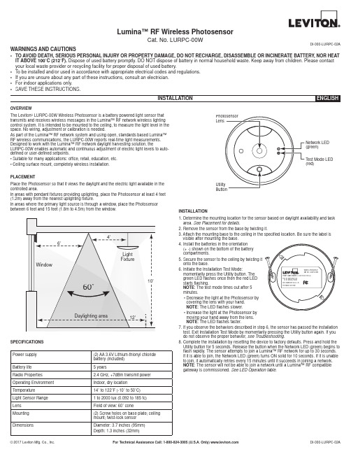
Lumina™ RF Wireless PhotosensorCat. No. LURPC-00WDI-000-LURPC-02AOVERVIEWThe Leviton ® LURPC-00W Wireless Photosensor is a battery powered light sensor that transmits and receives wireless messages in the Lumina™ RF network wireless lighting control system. It is intended to be mounted to the ceiling, to measure the light level in the space. No wiring, adjustment or calibration is needed.As part of the Lumina™ RF network system and using open, standards based Lumina™ RF wireless communications, the LURPC-00W reports real-time light measurements. Designed to work with the Lumina™ RF network daylight harvesting solution, theLURPC-00W enables automatic and continuous adjustment of electric light levels to auto-defined or user-defined setpoints.• Suitable for many applications: office, retail, education, etc.• Ceiling surface mount, completely wireless installation.PLACEMENTPlace the Photosensor so that it views the daylight and the electric light available in the controlled area.In areas with pendant fixtures providing uplighting, place the Photosensor at least 4 feet (1.2m) away from the nearest uplighting fixture.In areas where the primary light source is through a window, place the Photosensor between 6 feet and 15 feet (1.8m to 4.5m) from the window.SPECIFICATIONS INSTALLATION1. D etermine the mounting location for the sensor based on daylight availability and task area. See Placement for details .2. R emove the sensor from the base by twisting it.3. A ttach the mounting base to the ceiling in the specified location. Be sure the label is visible after mounting the base.4. I nstall the batteries in the orientation (+ -) shown on the bottom of the battery compartments.5. S ecure the sensor to the ceiling by twisting it onto the base.6. I nitiate the Installation Test Mode:momentarily press the Utility button. The green LED flashes once then the red LED starts flashing.NOTE : The test mode times out after 5 minutes.• D ecrease the light at the Photosensor by covering the lens with your hand. NOTE : The LED flashes slower.• I ncrease the light at the Photosensor by moving your hand away from the lens. NOTE : The LED flashes faster.7. I f you observe the behaviors described in step 6, the sensor has passed the installation test. Exit Installation Test Mode by momentarily pressing the Utility button again. If you do not observe the proper behavior, see Troubleshooting .8. C omplete the installation by resetting the device to factory defaults. Press and hold the Utility button for 5 seconds. Release the button when the Network LED (green) begins to flash rapidly. The sensor attempts to join a Lumina™ RF network for up to 30 seconds. If it is able to join, the Network LED (green) turns ON solid for 10 seconds. If it is unable to join, it automatically retries every 15 minutes until it succeeds in joining a network. NOTE : The sensor will not be able to join a network until a Lumina™ RF compatible gateway is commissioned. See LED Operation table .WARNINGS AND CAUTIONS• TO AVOID DEATH, SERIOUS PERSONAL INJURY OR PROPERTY DAMAGE, DO NOT RECHARGE, DISASSEMBLE OR INCINERATE BATTERY, NOR HEAT IT ABOVE 100˚C (212˚F). Dispose of used battery promptly. DO NOT dispose of battery in normal household waste. Keep away from children. Please contact your local waste provider or recycling facility for proper disposal of used battery.• To be installed and/or used in accordance with appropriate electrical codes and regulations.• If you are unsure about any part of these instructions, consult an electrician.• For indoor applications only.• SAVE THESE INSTRUCTIONS.Power supply (2) AA 3.6V Lithium-thionyl chloride battery (included)Battery life 5 yearsRadio Properties 2.4 GHz, +7dBm transmit power Operating Environment Indoor, dry location Temperature 14˚ to 122˚F (-10˚ to 50˚C)Light Sensor Range 1 to 2000 lux (0.092 to 185 fc)Lens Field of view: 60˚ coneMounting (2) Screw holes on base plate; ceiling mount; twist-lock sensor DimensionsDiameter: 3.7 inches (95mm)Depth: 1.3 inches (32mm)10’6’4’60˚WindowFixture12’Daylighting areaPhotosensor LensUtility Button Test Mode LED (red)Network LED (green)FOR CANADA ONLY:For warranty information and/or product returns, residents of Canada should contact Leviton in writing at Leviton Manufacturing of Canada Ltd to the attention of the Quality Assurance Department, 165 Hymus Blvd, Pointe-Claire (Quebec), Canada H9R 1E9 or by telephone at 1 800 405-5320.TROUBLESHOOTINGIf the Installation on Test procedure fails :• Make sure that the Photosensor lens is not obstructed and there is no debris on the lens.• Check to be sure the batteries are installed correctly, observe polarity.• Repeat the Installation on Test.No LEDs ever flash. Is the unit working?When the device is operating normally and it has joined a network, the LEDs are off . If you want to confirm that the batteries are not dead, you can initiate the Installation on Test Mode. See step 6 under installation.JOINING THE LUMINA™ RF LIGHTING CONTROL NETWORKAfter successfully completing the Installation Test the LURPC-00W is ready to communicate with the Lumina™ RF compatible gateway. * A network join can be re-triggered manually at any time using one of the following methods:• R eset to factory defaults: This causes the device to leave any network to which it is currently joined. Following the reset, the device attempts to join a network. Press and hold the Utility button for 5 seconds. Release the button when the Network LED (green) begins to flash rapidly.• A ctivate device: Press and hold the Utility button for 2 seconds. If the device is already joined to a network, the Network LED (green) flashes twice. If the device is not joined to a network, the Network LED (green) flashes rapidly and the device will attempt to join a network.TRADEMARK DISCLAIMER:Use herein of third party trademarks, service marks, trade names, brand names and/or product names are for informational purposes only, are/may be the trademarks of their respective owners; such use is not meant to imply affiliation, sponsorship, or endorsement.FCC COMPLIANCE STATEMENT:Contains FCC ID : NRH-ZB Z1-BThe enclosed device complies with Part 15 of the FCC Rules. Operation is subject to the following two conditions:(i.) This device may not cause harmful interference (ii.) This device must accept any interference received, including interference that may cause undesired operation. Any changes or modifications not expressly approved by Leviton could void the user’s authority to operate this equipment. This equipment has been tested and found to comply with the limits for a Class B digital device, pursuant to part 15 of the FCC Rules. These limits are designed to provide reasonable protection against harmful interference in a residential installation. This equipment generates uses and can radiate radio frequency energy and, if not installed and used in accordance with the instructions, may cause harmful interference to radio communications. However, there is no guarantee that interference will not occur in a particular installation. I f this equipment does cause harmful interference to radio or television reception, which can be determined by turning the equipment off and on, the user is encouraged to try to correct the interference by one or more of the following measures:• Reorient or relocate the receiving antenna.• Increase the separation between the equipment and receiver.• Connect the equipment into an outlet on a circuit different from that to which the receiver is connected.• Consult the dealer or an experienced radio/TV technician for help.INDUSTRY CANADA COMPLIANCE STATEMENT:Contains IC: 8984A-Z100BThis device complies with I ndustry Canada license-exempt RSS standard(s). Operation is subject to the following two conditions: (1) this device may not cause interference, and (2) this device must accept any interference, including interference that may cause undesired operation of the device. IMPORTANT! Any changes or modifications not expressly approved by the party responsible for compliance could void the user’s authority to operate this equipment. This Class B digital apparatus complies with Canadian ICES-003.LEVITON LIMITED WARRANTYLeviton warrants to the original consumer purchaser and not for the benefit of anyone else that products manufactured by Leviton under the Leviton brand name (“Product”) will be free from defects in material and workmanship for the time periods indicated below, whichever is shorter: • OmniPro II and Lumina Pro : three (3) years from installation or 42 months from manufacture date. • Omni LTe, Omni IIe, and Lumina : two (2) years from installation or 30 months from manufacture date. • BitWise Controllers, Accessories : two (2) years from installation or 30 months from manufacture date. • Lumina Gateway Controllers : two (2) years from installation or 30 months from manufacture date. • Thermostats, Accessories : two (2) years from installation or 30 months from manufacture date. • Batteries : Rechargeable batteries in products are warranted for ninety (90) days from date of purchase. Note : Primary (non-rechargeable) batteries shipped in products are not warranted. Products with Windows ® Operating Systems : During the warranty period, Leviton will restore corrupted operating systems to factory default at no charge, provided that the product has been used as originally intended. Installation of non-Leviton software or modification of the operating system voids this warranty. Leviton’s obligation under this Limited Warranty is limited to the repair or replacement, at Leviton’s option, of Product that fails due to defect in material or workmanship. Leviton reserves the right to replace product under this Limited Warranty with new or remanufactured product. Leviton will not be responsible for labor costs of removal or reinstallation of Product . The repaired or replaced product is then warranted under the terms of this Limited Warranty for the remainder of the Limited Warranty time period or ninety (90) days, whichever is longer. This Limited Warranty does not cover PC-based software products. Leviton is not responsible for conditions or applications beyond Leviton’s control. Leviton is not responsible for issues related to improper installation, including failure to follow written Installation and operation instructions, normalwear and tear, catastrophe, fault or negligence of the user or other problems external to the Product . To view complete warranty and instructions for returning product, please visit us at .LED OPERATIONARTWORK PRINT SPECIFICATIONSArtwork Print Specification Sheet Rev A11.eps。
E2E微型靠近传感器产品参数说明书

1E2E High performance in small sizes•pre-wired and M8 connector models •3mm, 4mm, 5.4mm and M5 sizes •response frequency up to 3kHzOrdering InformationSizeSensing Distance Connection Housing Material OutputOperation mode NO Operation mode NC dia 3mm shielded0.6mm pre-wired stainless steelPNP E2E-CR6B1E2E-CR6B2NPN E2E-CR6C1E2E-CR6C2dia 4mm0.8mmpre-wired PNP E2E-CR8B1E2E-CR8B2NPN E2E-CR8C1E2E-CR8C2M8 connectorPNP E2E-CR8B1-M5E2E-CR8B2-M5NPN E2E-CR8C1-M5E2E-CR8C2-M5M51mmpre-wired brassPNP E2E-X1B1E2E-X1B2NPN E2E-X1C1E2E-X1C2M8 connectorPNP E2E-X1B1-M5E2E-X1B2-M5NPN E2E-X1C1-M5E2E-X1C2-M5dia 5.4mmpre-wiredPNP E2E-C1B1E2E-C1B2NPNE2E-C1C1E2E-C1C22Inductive SensorsSpecificationsE2E-C @C @/B @, E2E-X1C @/B @ DC 3-wire ModelsNote:The response speed is an average value. Measurement conditions are as follows: standard sensing object, a distance of twice the standardsensing object, and a set distance of half the sensing distance.Size 3 dia.4 dia.M55.4 dia.TypeShieldedItemE2E-CR6C @/B @E2E-CR8C @/B @E2E-X1C @/B @E2E-C1C @/B @Sensing distance 0.6mm ±15%0.8 mm ±15% 1 mm ±15%Set distance 0 to 0.4mm0 to 0.5 mm0 to 0.7 mmDifferential travel 15% max. of sensing distanceSensing objectFerrous metal (The sensing distance decreases with non-ferrous metal, refer to Engineering Data .)Standard sensing object Iron: 3x3x1 mm Iron: 5x5x1mm Response speed (See note.)2kHz3kHzPower supply voltage (operating voltage range)12 to 24 VDC (10 to 30 VDC), ripple (p-p): 10% max.Current consumption 10mA max.17 mA max.Control output Load currentOpen-collector output, 80mA max.(at 30VDC max.)Open-collector output 100 mA max. (at 30 VDC max.)Residual voltage1 VDC max.(Load current: 80mA, Cable length: 2m)2 VDC max. (Load current: 100 mA , Cable length: 2 m)IndicatorOperation indicator (red LED)Operation mode (with sensing object approaching)C1/-B1 Models:NO C2/-B2 Models:NCFor details, refer to Timing Charts .Protection circuits Power supply reverse polarity protection, surge suppressor Ambient temperature Operating/Storage: –25°C to 70°C (with no icing or condensation)Ambient humidity Operating/Storage: 35% to 95%Temperature influence ±15% max. of sensing distance at 23︒C in the temperature range of –25°C to 70°C Voltage influence ±5% max. of sensing distance in the rated voltage range ±10%±2.5% max. of sensing distance in the rated voltage range ±15%Insulation resistance 50 M Ω min. (at 500 VDC) between current-carrying parts and case Dielectric strength 500 VAC at 50/60 Hz for 1 min between current-carrying parts and case Vibration resistance 10 to 55 Hz, 1.5-mm double amplitude for 2 hours each in X, Y, and Z directions Shock resistance 500 m/s 2 10 times each in X, Y, and Z directions Degree of protection IEC 60529: IP66IEC 60529 IP67 (Pre-wired models: JEM standard IP67g (waterproof, oil-proof))Connection method Pre-wired models (standard length 2 m), connector models Weight(packed state)Pre-wired models Approx. 60 g Connector models —Approx. 12 gApprox. 15 g —MaterialCaseStainless steel (SUS303)Brass-nickel platedSensing surface Heat-resistant ABS Clamping nuts Brass-nickel plated Toothed washerIron-zinc plated AccessoriesInstruction manual3E2E Output Circuits and Timing ChartsOutput CircuitsDC 3-wire ModelsTiming ChartsPin ArrangementE2E-CR8C @/CR8B @/X1C@/X1B@-M5 DC 3-wire ModelsIronCopperS t a inle ss s teel(S U S304) Br ass Al u min u m t = 1 mmIron S t a inle ss s teel (S U S304)Br assAl u min u mt = 1 mmS e n s i n g d i s t a n c e (m m )S ide length of s en s ing o b ject d (mm)S ide length of s en s ing o b ject d (mm)NPN Open-collector OutputBlue 3LoadBlack 4Brown 10 V100 ΩBlue 3LoadBlack 4Brown 10 VOutput100 ΩProximity sensor main circuitProximity sensor main circuit* Pin 4 is an NO contact, and pin 2 is an NC contact.* Pin 4 is an NO contact, and pin 2 is an NC contact.E2E-C/X @C @/B @NPN/PNP Open-collector OutputSensing object Control outputY es NoON OFF Operation indicator (red)ON OFF4Inductive SensorsPrecautionsMountingDo not tighten the nut with excessive force. A washer must be used with the nut.Note:The table below shows the tightening torques for part A andpart B nuts. In the previous examples, the nut is on the sensor head side (part B) and hence the tightening torque for part B applies. If this nut is in part A, the tightening torque for part A applies instead.Refer to the following to mount the E2E-CR8 and E2E-C1non-screw models.Tighten the screw to a torque of 0.2 N·m maximum to secure the E2E-CR8 and a torque of 0.4 N·m maximum to secure the E2E-C1.Effects of Surrounding MetalWhen mounting the E2E within a metal panel, ensure that the clearances given in the following table are maintained. Failure to maintain these distances may cause deterioration in the performance of the sensor.Mutual InterferenceWhen installing two or more Sensors face to face or side by side, ensure that the minimum distances given in the following table are maintained.Note:Values in parentheses apply to Sensors operating at different frequen-cies.ModelPart APart B LengthTorqueTorqueM51 N·mModel Item 3 dia. 4 dia.M5 5.4 dia.E2E-X @C @E2E-X @B @E2E-C @C @E2E-C @B @DC 3-wireShielded l 0 mm 0 mm 0 mm 0 mm d 3 mm 4 mm 5 mm 5.4 mm D 0 mm 0 mm 0 mm 0 mm m2 mm 2.4 mm3 mm3 mm n6 mm6 mm8 mm8 mmShielded Model Unshielded Model Part B Part APart B Part A8 to 21 mmM3 holeNo screw is provided with the E2E-CR8 or E2E-C1.d dia.Model Item 3 dia. 4 dia.M5 5.4 dia.E2E-X @B @E2E-X @C @E2E-C @B @E2E-C @C @DC 3-wireShielded A 20 mmB 15 mm5E2E Precautions for Safe UseThe colors in parentheses are previous wire colors.Precautions for Correct UseInstallation Power Reset TimeThe Proximity Sensor is ready to operate within 100 ms after power is supplied. If power supplies are connected to the Proximity Sensor and load respectively, be sure to supply power to the Proximity Sensor be-fore supplying power to the load.Power OFFThe Proximity Sensor may output a pulse signal when it is turned OFF. Therefore, it is recommended to turn OFF the load before turn-ing OFF the Proximity Sensor.Power Supply TransformerWhen using a DC power supply, make sure that the DC power supply has an insulated transformer. Do not use a DC power supply with an auto-transformer.Sensing ObjectMetal Coating:The sensing distances of the Proximity Sensor vary with the metal coating on sensing objects.WiringHigh-tension LinesWiring through Metal ConduitIf there is a power or high-tension line near the cable of the Proximity Sensor, wire the cable through an independent metal conduit to pre-vent against Proximity Sensor damage or malfunctioning.Cable Tractive ForceDo not pull on cables with tractive forces exceeding the following.MountingThe Proximity Sensor must not be subjected to excessive shock with a hammer when it is installed, otherwise the Proximity Sensor may be damaged or lose its water-resistivity.Environment Water ResistivityDo not use the Proximity Sensor underwater, outdoors, or in the rain.DC 3-wire ModelsSensorBrownBlackBlueLoadIncorrectDC 3-wire Models (NPN output)SensorBrownBlackBlueLoad(Load short- circuit)DC 3-wire Models (NPN output)SensorBrownBlueLoadBlackSensorBrownBlackLoadBlueIncorrectDC 3-wire ModelsSensorBrownBlueLoadIncorrectDiameterTractive force4 dia. max.30 N max.4 dia. min.50 N max.6Inductive SensorsOperating EnvironmentBe sure to use the Proximity Sensor within its operating ambient tem-perature range and do not use the Proximity Sensor outdoors so that its reliability and life expectancy can be maintained. Although the Proximity Sensor is water resistive, a cover to protect the ProximitySensor from water or water soluble machining oil is recommended so that its reliability and life expectancy can be maintained.Do not use the Proximity Sensor in an environment with chemical gas (e.g., strong alkaline or acid gasses including nitric, chromic, and con-centrated sulfuric acid gases).Connection to a PLC Required ConditionsConnection to a PLC is possible if the specifications of the PLC and the Proximity Sensor satisfy the following conditions. (The meanings of the symbols are given below.)1.The ON voltage of the PLC and the residual voltage of the Prox-imity Sensor must satisfy the following.V ON ≤ V CC – V R2.The OFF current of the PLC and the leakage current of the Prox-imity Sensor must satisfy the following.I OFF ≥ I leak(If the OFF current is not listed in the specifications, take it to be 1.3 mA.)3.The ON current of the PLC and the control output (I OUT ) of the Proximity Sensor must satisfy the following.I OUT(min) ≤ I ON ≤ I OUT(max)The ON current of the PLC will vary, however, with the power sup-ply voltage and the input impedance used as shown in the follow-ing equation.I ON = (V CC – V R – )/R INExampleIn this example, the above conditions are checked for when the PLC model is the C200H-ID212, the Proximity Sensor model is the E2E-X7D1-N, and the power supply voltage is 24 V .1.V ON (14.4 V) ≤ V CC (20.4 V) – V R (3 V) = 17.4 V: OK 2.I OFF (1.3 mA) ≥ I leak (0.8 mA): OK3.I ON = [V CC (20.4 V) – V R (3 V) – ≈4.5 mA Therefore,I OUT(min) (3 mA) ≤ I ON (4.5 mA): OKV ON : ON voltage of PLC (14.4 V)I ON : ON current of PLC (typ. 7 mA)I OFF : OFF current of PLC (1.3 mA)R IN : Input impedance of PLC (3 k Ω)V R : Output residual voltage of Proximity Sensor (3 V)I leak : Leakage current of Proximity Sensor (0.8 mA)I OUT : Control output of Proximity Sensor (3 to 100 mA)V CC : Power supply voltage (PLC: 20.4 to 26.4 V)Values in parentheses are for the following PLC model and Proximity Sensor model.PLC: C200H-ID212Proximity Sensor: E2E-X7D1-NNote:please refer to complete E2E/E2E2 datasheet for details on E2E-X7D1-NV PC V PC (4 V)]/R IN (3 k Ω)V PC : Internal residual voltage of PLC (4 V)Model Connection type Method DescriptionDC 3-wireAND (serial connection)The Sensors connected together must satisfy the following conditions.i L + (N –1) x i ≤ Upper-limit of control output of each SensorV S – N x V R ≥ Load operating voltage N: No. of SensorsV R : Residual voltage of each Sensor V S : Supply voltagei: Current consumption of the Sensor i L : Load currentIf the MY Relay, which operates at 24 VDC, is used as a load for example, a maximum of two Proximity Sensors can be connected to the load.LoadCorrect7E2E DimensionsNote:All units are in millimeters unless otherwise indicated.Pre-wired Models (Shielded)Dimensions 3 dia.4 dia.M55.4 dia.F (mm)3.3 dia.4.2 dia.5.5 dia.5.7 dia.+0.30+0.50+0.50+0.50ALL DIMENSIONS SHOWN ARE IN MILLIMETERS.To convert millimeters into inches, multiply by 0.03937. T o convert grams into ounces, multiply by 0.03527.Terms and Conditions of SaleCertain Precautions on Specifications and UseOMRON CANADA, INC. • HEAD OFFICEToronto, ON, Canada • 416.286.6465 • 866.986.6766 • OMRON ELECTRONICS DE MEXICO • HEAD OFFICEMéxico DF • 52.55.59.01.43.00 • 001.800.556.6766 •************** OMRON ELECTRONICS DE MEXICO • SALES OFFICEApodaca, N.L. • 52.81.11.56.99.20 • 001.800.556.6766 •************** OMRON ELETRÔNICA DO BRASIL LTDA • HEAD OFFICESão Paulo, SP, Brasil • 55.11.2101.6300 • .br OMRON ARGENTINA • SALES OFFICE Cono Sur • 54.11.4783.5300 OMRON CHILE • SALES OFFICE Santiago • 56.9.9917.3920 OTHER OMRON LATIN AMERICA SALES 54.11.4783.5300OMRON INDUSTRIAL AUTOMATION • THE AMERICAS HEADQUARTERSSchaumburg, IL USA • 847.843.7900 • 800.556.6766 • OMRON EUROpE B.V. • Wegalaan 67-69, NL-2132 JD, Hoofddorp, The Netherlands. •Tel: +31 (0) 23 568 13 00Fax: +31 (0) 23 568 13 88 •www.industrial.omron.euCat. No. D11E-EN-02A01/12 Note: Specifications are subject to change. © 2012 Omron Electronics LLC Printed in U.S.A.。
光电传感器SOOD、SOOE产品特性和范围概述说明书

光电传感器Subject to change –2018/102→Internet:/catalogue/...光电传感器SOOD,SOOE主要特性和产品范围一览产品范围一览派生型SOOD LEDSOOD 激光SOOE LED SOOE 激光→页码/Internet 漫反射式传感器,带背景抑制⏹⏹⏹⏹12,24对射式传感器⏹⏹⏹⏹18,28反射式传感器⏹⏹⏹⏹21,32反射式传感器,用于透明物体––⏹–35漫反射式传感器––⏹–38激光,对比传感器–––⏹42激光,距离传感器––⏹⏹46检测方法漫反射式传感器SOOE-DS这些传感器有时候被称为能量传感器,发射器和接收器同处一个壳体内。
发射出的光束直接被物体反射到接收器,计算反射光束的强度。
通过改变接收器(用IO-Link®、电位计或示教方法)的灵敏度可调节工作距离。
漫反射式传感器是成本效益最高的解决方案之一,安装也十分快捷。
不过,这些传感器不适用于一些应用场合,例如在强反射背景下检测轻微反光的物体。
此外,采用多种不同表面的物体(从材料、颜色或表面光洁度的角度出发)因为不同表面的反射特性不同,所以需要在不同的距离进行测量。
漫反射式传感器的优点在于强度区分。
•工作距离更长•经济性更佳•检测轻微反光的物体时更可靠-V-新产品光电传感器SOOD,SOOE 主要特性漫反射式传感器,带背景抑制工作距离并非通过能量来设定,而是通过光学三角测量。
全新且高精度的多像素技术(SOOE)有着优异的灵活性,通过IO-Link®设置。
带160x16像素的信号预处理的集成接收器是精确检测与距离测量的关键。
该接收器具备高分辨率和线性化,在检测范围上限有着独特的设定性能。
因此,物体检测几乎独立于背景中的其它物体之外,也与颜色、大小或表面光洁度无关。
这些设备仅要求有非常少量的漫反射。
带背景抑制的漫反射式传感器的优点•工作距离实际上与颜色和表面光洁度无关•还可用于闪光或反光的背景•检测距离的小差异•调节方便反射式传感器这些传感器的发射器和接收器也同处一个壳体内。
WORLD-BEAM 光电传感器 说明书

162WORLD-BEAM TM 传感器系列——QS18系列传感器Q S 18 S e r i e s •Email: sensors@163WORLD-BEAM TM 传感器系列——QS18系列传感器QS18 系列发射器接线图QS18传感器NPN 输出QS18传感器PNP 输出4针Pico 型接插件式164WORLD-BEAM TM 传感器系列——QS18系列传感器Q S 18 S e r i e s对射式(型号后缀为E&R )对射式(型号后缀为EB & RB)聚焦式、直接反射式及反射板式(型号后缀为CV15, CV45, D, LV & LP )直接反射式及宽光束直接反射式(型号后缀为DB & W)可调区域式(型号后缀为AF)塑料光纤式(型号后缀为FP)玻璃光纤式(型号后缀为F )特点 •Email: sensors@165WORLD-BEAM TM 传感器系列——QS18系列传感器QS18 系列小孔适用以下大孔适用以下尺寸光纤:尺寸光纤:• 0.25mm (0.01")• 0.75mm (0.03")• 0.5mm (0.02")• 1.0mm (0.04")• 1.5mm (0.06")塑料光纤安装方法 •Email: sensors@167WORLD-BEAM TM 传感器系列——QS18E 专家型系列传感器QS18 专家型系列* 上面仅列出了带2m(6.5')电缆的产品的型号,若在型号后加W/30则电缆长度为9m (如:QS18EN6LP W/30)QD 接插件产品型号• 4针150mm(6") Euro 型电缆式产品,在产品型号后加Q5。
(如:QS18EN6LPQ5)• 4针150mm(6") Pico 型电缆式产品,在产品型号后加Q 。
(如:QS18EN6LPQ )** 使用BRT-84反射板来标定(反射板需另购)*** 光形图和过量增益图与对应的标准QS18产品相同168WORLD-BEAM TM 传感器系列——QS18E 专家型系列传感器Q S 18 E x p e r t T M S e r i e sNPN 输出PNP 输出注:电缆式和接插件式接线图相同 •Email: sensors@169WORLD-BEAM TM 传感器系列——QS18E 专家型系列传感器QS18 专家型系列型号后缀为CV15, CV45, D, LP型号后缀为DB & W整套包括传感器M18 x 1安装螺母M3的配件安装指导,P/N69949M3的配件包括2个M3x0.5x20mm 的不锈钢螺丝2个M3x0.5不锈钢螺母2个M3不锈钢垫圈4针Euro 型电缆式接插件型号4针Pico 型接插件出线图(电缆端)4针Euro 型接插件出线图(电缆端)170WORLD-BEAM TM 传感器系列——QS18E 专家型系列传感器Q S 18 E x p e r t T M S e r i e s进入示教模式按住按键并保持按键绿灯:由亮变灭红灯:单闪进入示教模式按住按键并保持按键绿灯:由亮变灭红灯:单闪(仅能通过远程示教线完成,连续给示教线4个低电位脉冲,可锁定或解锁按键)绿灯:闪烁3次,然后常亮(传感器返回运作模式)QS186LE激光发射器• 自含式一级调制激光,具有较强的过量增益,扩展对射式产品的检测距离• 细小的有效光束可以用来检测细小的物体,并且可用来进行精确地定位• 明亮的光点和多种形状的光斑可以用来对物体做标记• 10 ~ 30V dc直流工作电源;将第三条线接电源的+V,可关掉激光172WORLD-BEAM TM 传感器系列——QS18LE 激光发射器Q S 18 L a s e r E m i t t e r* 上表仅列出了带2m 电缆的产品的型号。
SICK全系列产品简介

工业传感器
· 光电传感器 · 电感式接近开关 · 电容式接近开关 · 磁性接近传感器 · 磁性气缸传感器
工业仪表传感器
· 物位传感器 · 压力传感器 · 流量传感器 · 温度传感器
安全防护系统
· 安全激光扫描器 · 安全视觉传感器 · 安全光幕 · 多光束安全设备 · 单光束光电安全开关 · 反射镜和设备支架 · 升级套件
产品简介
SICK 产品简介
SICK 企业简介
丰
从单 SIC
工
工 安
自
SICK 简介 :
SICK成立于1946年,公司名称取自于公司创始人欧文·西克博士(Dr. Erwin Sick)的
姓氏,总公司位于德国西南部的瓦尔德基尔希市(Waldkirch)。SICK已在全球拥有
超过50个子公司和众多的销售机构。在2014年,雇员总数超过6,900人, 销售业绩
高
接近 11亿欧元。
公司创始人 欧文·西克博士(Dr. Erwin Sick)
西克中国简介 :
西克中国成立于1994年,为SICK在亚洲的重要分支机构之一。历经多年的发展与积
累,我们已成为极具影响力的智能传感器解决方案供应商,产品广泛应用于各行各
业,包括包装,食品饮料,机床,汽车,物流,交通,机场,电子,纺织等行业。
目前已在广州,上海,北京,青岛,香港等地设有分支机构,并形成了辐射全国各
主要区域的机构体系和业务网络。
运
西克中国总公司
2
全系列产品简介 | SICK
6000002/2015-07-29 如有改动,恕不另行通知
丰富的产品线,跨领域的应用
从 单一 的采 集 工 作到 复 杂生 产 过程 中 使 用 的 关键 传 感器 技 术: SICK 所 提供的 每一 款传 感 器解 决 方 案,都 具 有最 佳 的性 价 比和 安全 性。
RightSight 微型光电传感器指南说明书
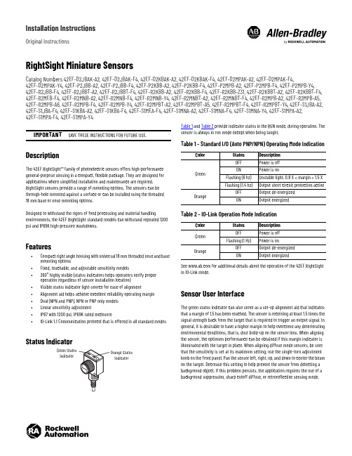
Installation InstructionsOriginal InstructionsRightSight Miniature SensorsCatalog Numbers 42EF-D2JBAK-A2, 42EF-D2JBAK-F4, 42EF-D2KBAK-A2, 42EF-D2KBAK-F4, 42EF-D2MPAK-A2, 42EF-D2MPAK-F4,42EF-D2MPAK-Y4, 42EF-P2JBB-A2, 42EF-P2JBB-F4, 42EF-P2KBB-A2, 42EF-P2KBB-F4, 42EF-P2MPB-A2, 42EF-P2MPB-F4, 42EF-P2MPB-Y4, 42EF-R2JBB-F4, 42EF-R2JBBT-A2, 42EF-R2JBBT-F4, 42EF-R2KBB-A2, 42EF-R2KBB-F4, 42EF-R2KBB-Z31, 42EF-R2KBBT-A2, 42EF-R2KBBT-F4, 42EF-R2MEB-F4, 42EF-R2MNB-A2, 42EF-R2MNB-F4, 42EF-R2MNB-Y4, 42EF-R2MNBT-A2, 42EF-R2MNBT-F4, 42EF-R2MPB-A2, 42EF-R2MPB-A5, 42EF-R2MPB-A6, 42EF-R2MPB-F4, 42EF-R2MPB-Y4, 42EF-R2MPBT-A2, 42EF-R2MPBT-A5, 42EF-R2MPBT-F4, 42EF-R2MPBT-Y4, 42EF-S1JBA-A2, 42EF-S1JBA-F4, 42EF-S1KBA-A2, 42EF-S1KBA-F4, 42EF-S1MEA-F4, 42EF-S1MNA-A2, 42EF-S1MNA-F4, 42EF-S1MNA-Y4, 42EF-S1MPA-A2, 42EF-S1MPA-F4, 42EF-S1MPA-Y4DescriptionThe 42EF RightSight™ family of photoelectric sensors offers high-performance general-purpose sensing in a compact, flexible package. They are designed for applications where simplified installation and maintenance are required. RightSight sensors provide a range of mounting options. The sensors can be through-hole mounted against a surface or can be installed using the threaded 18mm base or nose mounting options.Designed to withstand the rigors of food processing and material handlingenvironments, the 42EF RightSight standard models can withstand repeated 1200 psi and IP69K high-pressure washdowns.Features•Compact right angle housing with universal 18 mm threaded nose and base mounting options•Fixed, teachable, and adjustable sensitivity models•360° highly visible (status indicators helps operators verify proper operation regardless of sensor installation location)•Visible status indicator light-source for ease of alignment•Alignment aid helps achieve excellent reliability operating margin •Dual (NPN and PNP), NPN or PNP only models •Linear sensitivity adjustment•IP67 with 1200 psi; IP69K rated enclosure•IO-Link 1.1 Communication protocol that is offered in all standard modesStatus IndicatorTable 1 and Table 2 provide indicator status in the RUN mode, during operation. The sensor is always in run mode except when being taught.See for additional details about the operation of the 42EF RightSight in IO-Link mode.Sensor User InterfaceThe green status indicator can also serve as a set-up alignment aid that indicates that a margin of 1.5 has been reached. The sensor is receiving at least 1.5 times the signal strength back from the target that is required to trigger an output signal. In general, it is desirable to have a higher margin to help overcome any deteriorating environmental conditions, that is, dust build-up on the sensor lens. When aligning the sensor, the optimum performance can be obtained if this margin indicator is illuminated with the target in place. When aligning diffuse mode sensors, be sure that the sensitivity is set at its maximum setting; use the single-turn adjustment knob on the front panel. Pan the sensor left, right, up, and down to center the beam on the target. Decrease this setting to help prevent the sensor from detecting a background object. If this problem persists, the application requires the use of a background suppression, sharp cutoff diffuse, or retroreflective sensing mode.IMPORTANTSAVE THESE INSTRUCTIONS FOR FUTURE USE.IndicatorIndicatorTable 1 - Standard I/O (Auto PNP/NPN) Operating Mode IndicationColorStatus Description GreenOFF Power is off ON Power is onFlashing (6 hz)Unstable light: 0.8 X < margin < 1.5 X Flashing (1.4 hz)Output short circuit protection activeOrangeOFF Output de-energized ON Output energizedTable 2 - IO-Link Operation Mode IndicationColor Status Description GreenOFF Power is off Flashing (1 Hz)Power is onOrangeOFF Output de-energized ON Output energized2Rockwell Automation Publication 42EF-IN008B-EN-P - August 2020RightSight Miniature Sensors Installation InstructionsWiring DiagramsThe quick-disconnect connector is shown in the following diagrams. The pin numbers correspond to male connectors on the sensor.Figure 1 - Micro (M12) Male QD on Pigtail and Integral Pico (M8) Male QDOutput WiringFigure 2 - Light Operate PNP and NPN Models(42EF-D2JBAK-x , 42EF-P2JBB-x , 42EF-R2JBB-x , 42EF-S1JBB-x ) (a)Figure 3 - Dark Operate PNP and NPN Models(42EF-D2KBAK-x , 42EF-P2KBB-x , 42EF-R2KBB-x , 42EF-S1KBB-x ) (a)Figure 4 - PNP Complementary Models(42EF-D2MPAK-x , 42EF-P2MPB-x , 42EF-R2MPB-x , 42EF-S1MPB-x ) (a)Figure 5 - NPN Complementary Models(42EF-D2MNAK-x , 42EF-P2MNB-x , 42EF-R2MNB-x , 42EF-S1MNB-x ) (a)The IO-Link output pin 4 (black) does not support the connection of multiple sensors in series (for example, one sensor powering the next sensor). Theconnection of multiple sensors in series can be achieved when using pin 2 (white) outputs or by ordering a non-IO-Link catalog number. See theRockwell Automation® Knowledgebase or contact your local distributor for specific ordering information. For additional information about sensor operation in IO-Link mode, see publication 42EF-UM001.Approximate Dimensions [mm (in.)]Typical Response CurvesFigure 6 - Visible Red Polarized Retroreflective— 3.0 m Margin CurveFigure 7 - Visible Red Diffuse—500 mm Margin Curve(a)Replace the x in the catalog number with a suffix from Table 3.Table 3 - Connection TypesDescription Cat. No. Suffix2 m (6.6 ft) cable-A24-pin DC micro (M12) QD on 150 mm (6 in.) pigtail -F44-pin DC pico (M8) QD on 150 mm (6 in.) pigtail-Y412321M12 MaleM8 Male+V-VBlue (3)Black (4)White (2)Brown (1)PNP light operate or IO-Link NPN light operate or disabled (IO-Link operation default)+V-VBlue (3)Black (4)White (2)Brown (1)PNP dark operate or IO-Link NPN dark operate or disabled (IO-Link operation default)+V-VBlue (3)Black (4)White (2)Brown (1)PNP light operate or IO-Link PNP dark operate or disabled (IO-Link operation default)+V-VBlue (3)Black (4)White (2)Brown (1)NPN light operate or IO-LinkNPN dark operate or disabled (IO-Link operation default)Sensitivity Adjustment (diffuse and glass fiber-110100Distance to Reflector (mm)O p e r a t i n g M a r g i n0.110100011010001001100Distance (mm)M a r g i n (X )Rockwell Automation Publication 42EF-IN008B-EN-P - August 20203RightSight Miniature Sensors Installation InstructionsFigure 8 - Infrared Sharp Cutoff - 130 mm Margin CurveFigure 9 - Visible Red Polarized Retroreflective—3.0 m Beam PatternFigure 10 - Visible Red Diffuse—500 mm Beam PatternFigure 11 - Infrared Sharp Cutoff - 130 mm Beam PatternFigure 12 - Transmitted Beam Receiver—8 m Beam PatternFigure 13 - Transmitted Beam Receiver—Margin CurvesFigure 14 - Transmitted Beam Receiver—20 m Beam PatternAccessories1.010.0100.02.5425.4254Distance (m)O p e r a t i n g M a r g i nDistance (m)B e a m D i a m e t e r (m m )-535-11-3Distance to Target (mm)B e a m D i a m e t e r (m m )-8-6-4-20246812010080604020Distance to Target (mm)B e a m D i a m e t e r (m m )DescriptionCat. No.4-pin DC micro, 2 m (6.5 ft) cordset 889D-F4AC-2Swivel/tilt bracket (see Figure 16)60-2649Straight bracket60-2656Right angle bracket (see Figure 15)60-2657Mounting kit 60-2716Clamp style bracket 871A-BP18Flush mount adaptor60-25904-pin DC micro field-mount terminal chamber871A-TS4-DM 1.25 in. diameter reflector 92-473 in. diameter reflector92-39-0.2-0.15-0.1-0.0500.050.10.150.20.002.004.00 6.008.0010.00Distance (m)B e a m D i a m e t e r (m )1100100011010010Distance (m)O p e r a t i n g M a r g i n-0.5-0.4-0.3-0.2-0.100.10.20.30.40.50510152025Distance (m)B e a m D i a m e t e r (m m )Publication 42EF-IN008B-EN-P - August 2020 | Supersedes Publication 42EF-IN008A-EN-P - January 2016Copyright © 2020 Rockwell Automation, Inc. All rights reserved. Printed in the U.S.A.Rockwell Otomasyon Ticaret A.Ş. Kar Plaza İş Merkezi E Blok Kat:6 34752, İçerenköy, İstanbul, Tel: +90 (216) 5698400 EEE Yönetmeliğine UygundurAllen-Bradley, expanding human possibility, RightSight, and Rockwell Automation are trademarks of Rockwell Automation, Inc.Trademarks not belonging to Rockwell Automation are property of their respective companies.Your comments help us serve your documentation needs better. If you have any suggestions on how to improve our content, complete the form at rok.auto/docfeedback .For technical support, visit rok.auto/support.PN-59564210001372107 Ver 01Waste Electrical and Electronic Equipment (WEEE)Rockwell Automation maintains current product environmental compliance information on its website at rok.auto/pec .At the end of life, this equipment should be collected separately from any unsorted municipal waste.Figure 15 - Right Angle Bracket #60-2657Figure 16 - Swivel/Tilt Bracket #60-2649SpecificationsAttribute 42EF-*J*42EF-*K*42EF-*M*Certifications c-UL-us Listed and CE Marked for all applicable directives Vibration 10…55 Hz, 1 mm (0.04 in.) amplitude, meets or exceeds IEC 60947-5-2Shock 30 G with 1 ms pulse duration, meets or exceeds IEC 60947-5-2Relative humidity 5…95% (noncondensing)Ambient-light immunity •Incandescent light: 5000 lux •Sunlight: 20,000 lux User InterfaceStatus indicators •Green (power and margin)•Orange (output) Electrical Adjustments Fixed or adjustment knob by cat. no.Voltage10…30V DC, I-O link: 18…30V DC Current consumption 30 mA, maxSensor protection False pulse, reverse polarity, overload, short circuit Outputs Response time • 1 ms (diffuse, polarized retroreflective)• 4 ms (transmitted beam)Output type PNP and NPN PNP OR NPN(based on cat. no.)Load current 100 mA Leakage current, max •PNP: 0.1 mA •NPN: 0.3 mA Mechanical Housing material Mindel™Lens material Acrylic Cover material Udel™Supplied accessories 18 mm mounting nutEnvironmental Enclosure type rating NEMA 4X, 6P, IP67, IP69K; 1200 psi (8270 kPa) washdown Operating temperature -25…+70 °C (-13…+158 °F)Connection type•2 m (6.6 ft) cable•4-pin DC micro (M12) QD on 150 mm (5.9 in.) pigtail •4-pin DC pico (M8) QD on 150 mm (5.9 in.) pigtail。
德国施克 (SIC K) 传感器

26
四、施克每类子产品分类及介绍
迷你型光电传感器产品分类及介绍 1)迷你型光电传感器
迷你型光电传感器非常适合空间狭小的地方。多种产品型式可供 选择,包括漫反射式、对射式与镜反射式。 迷你型光电传感器有以下 17 个产品: a.G2S 迷你型光电传感器 特性规格: •灵敏度可调的漫反射BGS距离达120 mm •提供市场上最精确的BGS定位功能 • 提供市场同类型产品唯一能检测2%反射率的光电 • 镜反射距离达3米,远高于同类型产品1.5米的检测距离 •G2S可提供漫反射、镜反射和对射等不同检测方式型号 •G2S兼容市场主流产品的安装孔位,具备独特金属内孔 •G2S定位为OEM市场提供最具性价比的解决方案
12
三、施克每类产品分类及介绍
工业安全防护系统有以下 3 类产品:
1)光电保护设备
13
三、施克每类产品分类及介绍
工业安全防护系统有以下 3 类产品:
2)安全门开关 西克(SICK)安全门开关可以抵抗恶劣条件如碰撞和振动, 在很长的使用寿命中能够可靠地保证开关和锁定。有机电式和非 接触式,有塑料和金属型号。
8
三、施克每类产品分类及介绍
工业传感器有以下 5 类产品:
2)标识传感器
9
三、施克每类产品分类及介绍
工业传感器有以下 5 类产品:
3)接近传感器 接近传感器可在限定的检测范围内检测到金属物体。感 应面的直径大小是检测距离的决定因素。从几厘米到几十厘米, 准确度与灵敏度让金属检测变得可靠而简单。
10
23
三、施克每类产品分类及介绍
过程仪表传感器有以下4类产品:
2)液位传感器-料位传感器 不管是进行连续的液位测量、开关点式的液位测量还是 它们的组合,西克(SICK)都能为工艺过程、存储或保护提供广泛 的解决方案。西克(SICK)的液位传感器/开关为不同行业的用户提 供了实时与全天候的监控,使自动化过程更加顺畅可靠。
单极宽视动力感应灯控制器IcSN2, IPVN2说明书

Single Pole Wide View Motion Activated Light ControlCat. Nos. IPSN2, IPVN2 - INDOOR USE ONLYRatings: 120VAC, 60Hz 300W 2.5A Resistive, 150W LED and CFL, 1/6HPPK-A3325-10-00-2AWARNINGS• TO AVOID FIRE, SHOCK OR DEATH: TURN OFF POWER AT CIRCUIT BREAKER OR FUSE AND TEST THAT THE POWER IS OFF BEFORE WIRING!• TO AVOID PERSONAL INJURY OR PROPERTY DAMAGE, DO NOT install to control a receptacle, or a load in excess of the specified rating.• To be installed and/or used in accordance with electrical codes and regulations.• If you are not sure about any part of these instructions, consult an electrician.CAUTIONS• Clean outer surface gently with damp cloth only. DO NOT use soaps or cleaning liquids.• No user serviceable components. DO NOT attempt to service or repair.• Use this device WITH COPPER CLAD WIRE ONLY .InstallationWARNING: TO AVOID FIRE, SHOCK OR DEATH, turn off power at circuit breaker or fuse and test that the power is off before wiring.2. Wire.W orking on one connection at a time, connect wires as shown.NOTE: Make sure the line and load are properly oriented or the device will notwork.NOTE : Neutral connection is required.1. I dentify your wires (most common):NOTE: Neutral wire is required for operation. If the wiring in the wall box does not resemble this configuration, consult an electrician.You Will Need:• Slotted/Phillips screwdriver • Pencil • Electrical tape • Cutters • Pliers • RulerMounting LocationFeatures• C at. Nos. IPSN2 and IPVN2 have a sensing area of coverage of 30 ft x 30 ft and a sensing angle of 180°. See coverage diagram for details.• A djustable ambient light (IPSN2 only) and time delay controls are located on the front of the device. See adjustment setting section for details.• Indicator light alerts the user of device status.• A djustable time delay setting for 30 seconds, 5 minutes, 15 minutes and 30 minutes.• T he device responds to temperature changes and care should be taken when mounting the device.• D O NOT mount directly above a heat source, in alocation where hot or cold drafts will blow directly on the sensor, or where unintended motion (e.g., hallway traffic) will be within sensor's field-of-view.5. To adjust settings• Remove wallplate and sensor face (see section "Changing Your Device Cover".)• Adjust dials with small screwdriver.6. Dial DescriptionsAutomatic ON Mode (default setting):4. Default Dial SettingsNOTE: For IPVN2 California Title 24 applications, set the Time setting to 0, 1 or 2.3. Test.• R estore power.• W• I after power is applied. • I PVN2: press push pad. Lights should turn ON.NOTE: If lights do not turn ON, refer to the "What to do if..." section.(IPSN2 only)LowSome lightMost lightManual ON7a. Mode Description - IPVN2TimeAmbient Light Level(30 sec.)(30 min.)(5 min.)(15 min.)purposes, IPSN2 shown .NOTE : For IPSN2 ,using the push pad to turn off the load will temporarily bypass Auto On.For Technical Assistance Call: 1-800-824-3005 (USA Only)or 1-800-405-5320 (Canada Only) PK-A3325-10-00-2A© 2020 Leviton Mfg. Co., Inc.FCC STATEMENT: This device complies with Part 15 of the FCC Rules. Operation is subject to following two conditions: (1) this device may not cause harmful interference, and (2) this device must accept any interference received, including interference that may cause undesired operation of the device. This equipment has been tested and found to comply with the limits for a Class B Digital Device, pursuant to Part 15 of the FCC Rules. These limits are designed to provide reasonable protectionagainst harmful interference in a residential installation. This equipment generates, uses, and can radiate radio frequency energy and, if not installed and used in accordance with the instructions, may cause harmful interference to radio communications. However, there is no guarantee that interference will not occur in a particular installation. If this equipment does cause harmful interference to radio or television reception, which can be determined by turning the equipment OFF and ON, the user is encouraged to try to correct the interference by one or more of the following measures:• Reorient or relocate the receiving Antenna. • Increase the separation between the equipment and the receiver.• Connect the equipment into an outlet on a circuit different from that to which the receiver is connected. • Consult the dealer or an experienced radio/tv technician for help.FCC CAUTION: Any changes or modifications not expressly approved by Leviton Manufacturing Co., Inc., could void the user's authority to operate the equipment.FOR CANADA ONLYFor warranty information and/or product returns, residents of Canada should contact Leviton in writing at Leviton Manufacturing of Canada Ltd to the attention of the Quality Assurance Department, 165 Hymus Blvd, Pointe-Claire (Quebec), Canada H9R 1E9 or by telephone at 1-800-405-5320.LIMITED 5 YEAR WARRANTY For Leviton’s limited product warranty, go to . For a printed copy of the warranty,call 1-800-824-3005.Patents covering this product, if any, can be found on /patents.Sensing Area Coverage1. H orizontal field of view:2. Vertical field of view:8. Mount.Turn off power at circuit breaker before completing the installation. • G ently push wires into wall box. Screw light control to box.• I nstall wallplate base and snap on Decora ® wallplate.• Restore power.9. M anual Operation• Press push pad to manually turn on the load.Internal time will activate and turn off load when set time out expires.• Press and release push pad to manually turn off load.pad7b. Mode Descriptions - IPSN2。
OsiSense XUM小型光电传感器说明书

OsiSense® XUM Miniature Photoelectric SensorsHigh performancein a small packageOffering long sensing distances and resistance to interference and light sources>Easy to installContributes to machine compactnessWider adjustment range>EconomicalIncreases profi tability>Readily availableContributes to machine performanceContentsMiniature diffuse, polarized retrorefl ective, thru-beam dedicated models and multimode photoelectric sensorsIntroduction p 2 and 3Three-wire, plastic dedicated models p 4 to 7Three-wire, metal dedicated models p 8 to 11Three-wire, plastic multimode p 12 and 13NOTE: Sensors described in this catalog are designed to be used for standard industrial presence sensingapplications. These sensors do not include the self-checking redundant circuitry necessary to allow fortheir use in safety applications.>Contributes to machine compactnessEasy to install:Compact product, the most commonly used standard size• Long sensing distances: up to 5 m (16.40 ft) retrore fl ective, 15 m (49.21 ft) thru-beam, and 1 m (3.28 ft) diffuse • High insensitivity to light sources: withstands up to 40,000 lux natural light/10,000 lux incandescent light • Good resistance to severe environments: -30 to 60 °C (-22 to 140 °F) with IP67 degree of protection rating (IP69 K or IP67 G available)50%50% energy consumption: twice as many sensors can be placed on thesame power supply >Increases profi tabilityEconomical and Simple:• NO/NC con fi guration switch located on the bottom of the sensor for protection against accidental adjustment• Output LED on the front face of thru-beam sensors for easier alignment during installation >Selection guide XUM photoelectric sensors 3-wire DC Polarized Retrore fl ective DiffuseM82 m cable 2 m cable 1 (3.28) 5 (16.40)M8 2 m cable Thru-Beam 15 (49.21) with adjustable sensitivitytransmitter + receiver 12–24 Vdc with protection against reverse polarityNO/NC con fi gurable par switchIP65, IP67 * For multimode thru-beam applications, see page 12 for appropriate transmitter and receiver selection.100%availabilitythroughoutthe world >Contributes to machine performanceReadily available:• Robust products designed to meet your needs• Particularly well suited for machines used in the assembly and packaging sectors, the automotive industry, conveying, etc.Packaging Automotive Materials handling Multimode 0...10 (32.81)depending on mode3-wire DCwith adjustable sensitivity IP67, IP69 K, IP67 G 12–24 Vdc with protection against reverse polarity Fixed NO or NC, PNP or NPN XUM9BPANL2 XUM9BNANL22 m cable5 (16.40) with re fl ector XUZC50Polarized Retrore fl ective XUM9BPBNL2XUM9BNBNL22 m cable 15 (49.21)Thru-Beamtransmitter + receiverDiffuse 2 m cable 0.77 (2.53) XUM5BPANL2 XUM5BNANL2XUM5BPBNL2 XUM5BNBNL2System Supplym (ft) M8XUM5A p CNM8XUZ C08567XUZMSV pp XUZMSH pp XUZMU01Catalog Numbers OsiSense® Photoelectric sensorsOptimumMiniature design, plasticThree-wire DC solid-state outputNO/NC confi guration switchXUZAM04524754XUZAM03524753Distance (m)Parallelmovement(cm)Vertical movementHorizontal movementParallelmovement(cm)XUZ C50Parallelmovement(cm)Distance (m) wiring diagramscurvesOptimumMiniature design, plasticThree-wire DC solid-state outputNO/NC confi guration switchDiffuse system, polarized retrorefl ective system (mm)Pre-cabled version Connector versionDescription - XUM5A p CNL2, XUM9A p CNL2Dimensions - XUM5A p CNL2,XUM9A p CNL2Description - XUM5A p CNM8,XUM9A p CNM8Dimensions - XUM5A p CNM8,XUM9A p CNM8(1) Confi guration switch(2) Output state LED(3) Stability and power-on LEDR: Reception, T: Transmission(1) Potentiometer(1) Confi guration switch(2) Output state LED(3) Stability and power-on LEDR: Reception, T: Transmission(1) Potentiometer(4) Adjustment potentiometer(5) Power-on LEDT: Transmission(1) Potentiometer(1) Confi guration switch(2) Output state LEDR: Reception(1) Output state LED on front face(4) Adjustment potentiometer(5) Power-on LEDT: Transmission(1) Potentiometer(1) Confi guration switch(2) Output state LED(3) Stability and power-on LEDR: Reception(1) Output state LED on front faceNO/NC confi guration switchNO/NC confi guration switchXUZ C08XUM 2B2KCL2T XUM 2B pp NL2RXUZ AM81Catalog Numbers OsiSense ® Photoelectric sensorsApplicationMiniature design, metalThree-wire DC solid-state output(+) BN (Brown)OUT/Output BK (Black)P a r a l l e l m o v e m e n t (c m )Horizontal movementP a r a l l e l m o v e m e n t (c m )XUZ C50P a r a l l el m o v e m e n t (cm )Distance (m)Characteristics, schemes, curvesOsiSense ® Photoelectric sensorsApplicationMiniature design, metalThree-wire DC solid-state outputDiffuse system (mm)Description - XUM 5B pp NL2Dimensions - XUM 5B pp NL2(3) Adjustment potentiometer.R: Reception, T: Transmission.Polarized retrorefl ective system (mm)NL2Dimensions - XUM 9B pp NL2Description - XUM 9B ppDescription - XUM 2BKCNL2T Dimensions - XUM 2BKCNL2T Dimensions - XUM 2B pp NL2R(2) Stability and power-on LED.Accessories (mm)Refl ectors Mounting bracket XUZ C08XUZ C50XUZ AM81(1) 2 x M3(1) Elongated holes 4.5 x 8OsiSense ® Photoelectric sensorsMulti-modeMiniature designThree-wire DC supply, solid-state outputXUM0APSAL5.Dimensions (mm)XUM0A ppp L2XUM0A ppp M8Elbowed connector501543_1501542_1XUM0A ppp M8XUM0A ppp L2XUZC50XUZ M2003XUZ2001XUZ 2003XUZ A50Catalog Numbers,dimensionsOsiSense ® Photoelectric sensorsMulti-modeMiniature designThree-wire DC solid-state output1 (+)4 OUT/Output 2 beam break input (1)(+) BN (Brown)OUT/Output BK (Black)Beam break input VI (Violet) (1)2/VI input:- not connected: beam madefl ection coef fi cientSpeci fi cations, wiring diagrams,curves(1) Beam break input on thru-beam transmitter only.The information and dimensions in this catalog are provided for the convenience of our customers. While this information is believed to be accurate, Schneider Electric reserves the right to makeupdates and changes without prior notifi cation and assumes no liability for any errors or omissions. Design: Schneider ElectricPhotos: Schneider Electric© 2010 Schneider Electric. All Rights Reserved.April 20109 0 0 6 C T 1 0 0 3Schneider Electric USA, Schneider Electric SensorCompetency Center1875 Founders DriveDayton OH 45420(800) 435-2121。
IDEC SA1A、SA1B薄型光电传感器
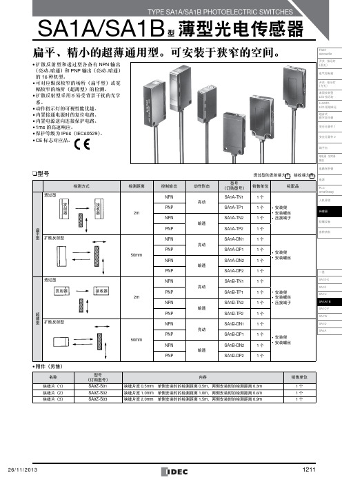
主
黑色
电
负载
路
蓝色 0V
12~24V DC 12~24V DC
• SA1A-TP1/TP2,SA1B-TP1/TP2
茶色+V
ห้องสมุดไป่ตู้
接主 收电 器路
黑色
负载
蓝色 0V
发主 射电 器路
橙色/紫色 橙色/紫色
茶色+V
12~24V DC
(橙色和紫色的条纹线为同步线)
• SA1A-DP1/DP2,SA1B-DP1/DP2
电气控制箱
开关 · 指示灯 (方孔) 表面安装型 LED 指示灯 LUMIFA LED 照明单元 组合式 数字显示器
安全元器件 1
安全元器件 2
端子台
继电器 · 定时器 · 插座
❏型号
透过型
检测方式
发
接
射
收
器
器
扁 平 型 扩散反射型
透过型 发射器
超 薄 型 扩散反射型
接收器
检测距离 2m
50mm 2m
注 :上述为亮动输出型的步骤,若为暗通输出型,则动作指示灯的点亮与 熄灭相反。
3. 设置
(1)相邻连接安装光电传感器时,为避免遭受接收光的互扰,请 保证相邻光电传感器间有足够的间距,或使用遮光板等。此 外,请注意周围来自地板或墙壁等的反射光。
(2)使用透过型且需要进行改善互扰对策时,或检测物体在 ø5mm 以下时,请在透镜面上粘贴狭缝片(另售)后使用。
电路保护器
透过型的发射端为 T ,接收端为 R 。
电源
销售单位 1个
标配品
PLC · SmartRelay
人机界面
1 个 • 安装架 • 安装螺丝
Omron E3F2 线性光电传感器说明书
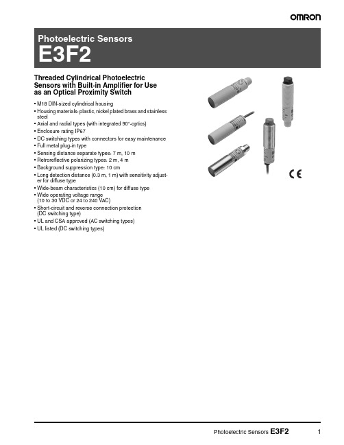
Threaded Cylindrical PhotoelectricSensors with Built-in Amplifier for Use as an Optical Proximity Switch•M18 DIN-sized cylindrical housing•Housing materials: plastic, nickel plated brass and stainless steel•Axial and radial types (with integrated 90°-optics)•Enclosure rating IP67•DC switching types with connectors for easy maintenance •Full metal plug-in type•Sensing distance separate types: 7 m, 10 m •Retroreflective polarizing types: 2 m, 4 m•Background suppression type: 10 cm•Long detection distance (0.3 m, 1 m) with sensitivity adjust-er for diffuse type•Wide-beam characteristics (10 cm) for diffuse type •Wide operating voltage range(10 to 30 VDC or 24 to 240 VAC)•Short-circuit and reverse connection protection(DC switching type)•UL and CSA approved (AC switching types)•UL listed (DC switching types)Ordering Information■DC-Switching ModelsHousing Material: PlasticNote:Shaded models are normally stocked.Note:Standard cable length is 2 m. Models provided with a 5 m long cable are available. When ordering, specify the cable length by adding thelength of the cable (e.g. E3F2-R2RB4 2M or E3F2-R2RB4 5M). For other cable length please contact your OMRON sales representative.*1)with slit E39-ES18*2)with reflector E39-R1*3)with reflector E39-R1S■Housing material: Metal (Nickel plated brass)Note:Shaded models are normally stocked.Note:Standard cable length is 2 m. Models provided with a 5 m long cable are available. When ordering, specify the cable length by adding thelength of the cable (e.g. E3F2-R2RB4 2M or E3F2-R2RB4 5M). For other cable length please contact your OMRON sales representative.*1)with reflector E39-R1*2)with reflector E39-R1S■Housing material: Metal (Stainless steel)Note:Shaded models are normally stocked.Note:Standard cable length is 2 m. Models provided with a 5 m long cable are available. When ordering, specify the cable length by adding thelength of the cable (e.g. E3F2-R2RB4-S 2M or E3F2-R2RB4-S 5M). For other cable length please contact your OMRON sales representa-tive.■AC-Switching ModelsHousing material: PlasticNote:Shaded models are normally stocked.Note:Standard cable length is 2 m. Models provided with a 5 m long cable are available. When ordering, specify the cable length by adding thelength of the cable (e.g. E3F2-R2Z1 2M or E3F2-R2Z1 5M). For other cable length please contact your OMRON sales representative.■Accessories (Order Separately)Note:Shaded models are normally stocked.For detailed information about Accessories, refer to the main chapter “Accessories” at the end of the document.Note:1.T ypical sensing distance corresponds to 80% of the max. sensing distance. For details, please refer to “Engineering Data”.■Sensor I/O ConnectorsNote:Shaded models are normally stocked.NameSensing distance (typical) [1.]ModelRemarkReflectors0.1 - 3.7 m (axial)0.1 - 2.4 m (radial)E39-R160 x 40 mm (included in some models)0.1 - 4.3 m (axial)E39-R1S for E3F2-R40.1 - 4.2 m (axial)0.1 - 2.7 m (radial)E39-R784 mm 0.1 - 5.3 m (axial)0.1 - 3.1 m (radial)E39-R8100 x 100 mm 0.1 - 4.3 m (axial)E39-R4080 x 80 mm Tape ReflectorsE39-RSA 35 x 10 mm E39-RSB 35 x 40 mm E39-RS380 x 70 mmLens Cap E39-F31Mounting Bracket Y92E-B18screw mountY92E-G18quick access mounting SlitE39-ES18for E3F2-10@ - precision detectionSpecifications■Ratings / Characteristics of DC Switching ModelsNote:1.For stable sensing distance in detail, please refer to “Engineering Data”2.Typical sensing distance corresponds to 80% of the max. sensing distance.3.The enclosure rating IP67 of OMRON internal standards correspond to stricter test requirements than the standard IEC 60529 (refer to chapter “Precautions”)4.For other cable materials (e.g. PUR) please contact your OMRON sales representative.5.Material-specification for stainless steel housing case: 1.4305 (W.-No.), 303 (AISI), 2346 (SS). For other stainless steel materials please contact your OMRON sales representative.6.with slit E39-ES187.PNP models -B4: V CC to V CC -2.5 V: Emitting OFF (Source current: 3 mA max.) / Open or 0 to 2.5 V: Emitting ON (Leakage current: 0.1mA max.)NPN models -C4: 0 to 2.5 V: Emitting OFF (Source current: 3 mA max.) / Open or Vcc to Vcc -2.5 V: Emitting ON (Leakage current: 0.1mA max.)ItemE3F2-7@E3F2-10@E3F2-R2@4-@E3F2-R2R @E3F2-R4@-@E3F2-DS10@E3F2-DS30@E3F2-D1@4-@E3F2-LS10@4-@Sensing methodThrough-beam Retroreflective Diffuse reflective - multi purpose - Precision detection [6.]- test inputNon-polarizingPolarizingWide beam characteristicAdjustable sensing distance Background suppressionPower supply voltage 10 to 30 V DC 12 to 24 V DC 10 to 30 V DC Current consumption 50 mA max.25 mA max.30 mA max.25 mA max.30 mA max.Rated sensing distance [1.]7 m 10 m 0.1 - 2 m(with reflector E39-R1)0.1 - 4 m(with reflector E39-R1S)0.1 m(5 x 5 cm white mat paper)0.3 m(10 x 10 cm white mat paper)1 m(30 x 30 cm white mat paper)0.1 m(10 x 10 cm white mat paper)T ypical sensing distance for different reflector types (ref. to accesso-ries) [2.]–E39-R1: 4.0 m E39-R7: 4.5 m E39-R8:5.3 m E39-R1:axial3.7 m radial 2.4 m E39-R7:axial4.2 m radial 2.7 m E39-R8:axial5.3 m radial 3.1 mE39-R1S:4.3 m E39-R7: 4.8 m E39-R8: 5.6 mE39-R40:4.3 m E39-RS3: 2 m –Standard object Opaque: 11 mm dia. min.Opaque: 56 mm dia. min.–Directional angle 3° to 20°–Differential travel (hysteresis)–20% max.5% max Black/white error –3%Response time Operation and Reset: 2.5 ms max. 1 ms max 2.5 ms max. 1 ms max.Control output T ransistor (open collector), load current: 100 mA max. (residual voltage: 2 V max.)Power reset time 50 ms 100 ms max.50 ms 100 msAmbient illumination Incandescent lamp:3000 lx max. / Sunlight:10000 lx max.Ambient temperature Operating: -25 to 55 °C / Storage: -30 to 70 °C (with no icing or condensation)Ambient humidity Operating: 35% to 85% / Storage: 35% to 95% (without condensation)Insulation resistance 20 M Ω min. at 500 V DC between energized parts and caseDielectric strength 1000 VAC max., 50 / 60 Hz for 1 min between energized parts and case Vibration resistance 10 to 55 Hz, 1.5 mm double amplitude for 2 hrs each direction (X, Y, Z)Shock resistance Destruction: 500 m/s 2 each direction (X, Y , Z)Enclosure ratings IP67 [3.]; NEMA 1, 2, 4Light source Infrared LED (880 nm/850 nm)Red LED (660 nm)Infrared LED (880 nm)Red LED (660 nm)IndicatorsLight incident / power indi-cator for light source (red)Output (orange) / light emission (red)Light incident / power indicator for light source (red)Light incident (red) / stability (green)Light incident / power indicator for light source (red)Light incident (red) / stability (green)Output indicator (orange) / sta-bility (green)Sensitivity adjustment Fixed Fixed / AdjustableFixed Adjustable FixedConnection method 2 m, 5 m pre-wired cable (PVC, dia. 4 mm (18 / 0.12) [4.]) or M12-connector T est Input–[7.]–Operation mode Light-ON or Dark-ON selectable by wiringWeight (approx.)Plastic case pre-wired (2 m)120 g 60 g connector40 g 20 g Metal case pre-wired (2 m)180 g 90 g connector 120 g 50 gCircuit protection Output short-circuit and power supply reverse polarity Housing materialsPlastic (case: ABS; lens: PMMA)Nickel brass Nickel brass –Nickel brass Nickel brassNickel brass Nickel brass Nickel brass Nickel brass Stainless steel [5.]––Stainless steel [5.]–Stainless steel [5.]Stainless steel [5.]––■Ratings / Characteristics of AC Switching ModelsNote:1.For stable sensing distance in detail, please refer to “Engineering Data”2.T ypical sensing distance corresponds to 80% of the max. sensing distance.3.The enclosure rating IP67 of OMRON internal standards correspond to stricter test requirements than the standard IEC 60529 (refer to chapter “Precautions”)ItemE3F2-3Z1E3F2-3Z2E3F2-R2Z1E3F2-R2Z2E3F2-DS10Z1E3F2-DS10Z2Sensing method Through-beamNon-polarizing RetroreflectiveDiffuse reflective(wide-beam characteristic)Power supply voltage 24 to 240 VAC ±10%, 50 / 60 Hz Current consumption 10 mA max. 5 mA max.Rated sensing distance[1.] 3 m 0.1 - 2 m(with reflector E39-R1)0.1 m(5 x 5 cm white mat paper)Typical sensing distance for dif-ferent reflector types [2.]–E39-R1: 3,4 m E39-R7: 3,9 m E39-R8: 5,2 m–Detectable object Opaque object: 11 mm min.Opaque object: 56 mm min.Opaque objects Directional angle 3° to 20°–Differential travel –20% max.Response time 30 ms max.Control output AC solid state (SCR) 200 mA max.; residual voltage: 5 V max. at 200 mA Power reset time 100 msAmbient illumination Incandescent lamp: 3000 lx max. Sunlight: 10000 lx max.Ambient temperature Operating: -25 to 55 °C / Storage: -30 to 70 °C (with no icing or condensation)Ambient humidity Operating: 35% to 85% / Storage: 35% to 95% (without condensation)Insulation resistance 20 M Ω min. at 500 V DC between energized parts and case Dielectric strength 1500 VAC, 50 / 60 Hz for 1 min between energized parts and case Vibration resistance 10 to 55 Hz, 1.5 mm double amplitude for 2 hrs each direction (X, Y , Z)Shock resistance 500 m/sqr (approx. 50 g) for each direction (X, Y , Z)Enclosure rating IP67 [3.]; NEMA 1, 2, 4Light source Infrared LED (880 nm)IndicatorsLight incident/power indicator for light source (red)Sensitivity adjustment FixedConnection method 2 m, 5 m pre-wired cable (PVC dia. 4 mm (14 / 0.15))Operation mode Light-ON or Dark-ON (fixed)Circuit protection NoneWeight (approx.)110 g (pre-wired 2 m cable)Housing materialsPlastic (case: ABS; lens: PMMA)Engineering Data (Typical)■Operating Range (typical)Through-beam Models (axial) E3F2-7@4-@Through-beam Models (axial)E3F2-3Z@Through-beam Models (axial)E3F2-10@Retroreflective Models (axial) E3F2-R2@4-@ (non polarizing) and reflectors Retroreflective Models (axial)E3F2-R2Z@ (non polarizing)and reflectorsRetroreflective Models (axial)E3F2-R2R@4-@ (polarizing)and reflectorsRetro-reflective Models (axial) E3F2-R4@4@-@ (polarizing)Retroreflective Models (radial) E3F2-R2R@41-@ (polarizing) and reflectors■Excess Gain Ratio vs. Distance (typical)Diffuse reflective Models (axial)E3F2-DS10@4-@ (wide-beam type)Diffuse reflective Models (axial)E3F2-DS10Z-@ (wide-beam type)Diffuse reflective Models (axial)E3F2-DS30@4-@Diffuse reflective Models (radial)E3F2-DS30@41-@Diffuse reflective Models (axial)E3F2-D1@4-@Through-beam Models (axial)E3F2-7@4-@Through-beam Models (axial)E3F2-3Z @Through-beam Models (axial)E3F2-10@Retroreflective Models (axial)E3F2-R2@4-@ (non polarizing)and reflectorsRetroreflective Models (axial)E3F2-R2Z @ (non polarizing)Retroreflective Models (axial)E3F2-R2R @4-@ (polarizing)Retroreflective Models (axial)E3F2-R4@4@-@Retroreflective Models (radial)E3F2-R2R @41-@ (polarizing)and reflectorsDiffuse reflective Models (axial)E3F2-DS10@4-@ (wide-beam type)Diffuse reflective Models (axial)E3F2-DS10Z-@ (wide-beam type)Diffuse reflective Models (axial)E3F2-DS30@4-@Diffuse reflective Models (radial)E3F2-DS30@41-@Diffuse reflective Models (axial)E3F2-D1@4-@■Light spot vs. sensing distance■Incline (left and right)■Incline (up and down)Background suppression Models E3F2-LS @Background suppression Models E3F2-LS @Background suppression Models E3F2-LS @■Object material vs. sensing distanceBackground suppression Models E3F2-LS @Operation■Output CircuitsStructure of Sensor I/O Connector■PNP OutputClassification Wire color Connector pin e DCBrown Power supply (+V)White Mode s election Lon/Don Blue Power supply (0 V)BlackOutput1234Note:T erminal numbers for connector type.■NPN Output■AC OutputDimensions Note: All units are in millimeters unless otherwise indicated ■DC-Switching Models, plastic, axial type■DC-Switching Models, plastic, radial type■DC-Switching Models, metal (brass and stainless steel), axial type■DC-Switching Models, metal (brass and stainless steel), radial type Array■AC-Switching Models, plastic, axial type■Accessories (Order Separately)E39-RSBSlit (for precision detection with E3F2-10@) E39-ES1830Two tightening nuts161 214PrecautionsThe E3F2 Photoelectric Sensor is not a safety component for ensur-ing the safety of people which is defined in EC directive (91/368/ EEC) and covered by separate European standards or by any other regulations or standards.■Degree of protectionThe E3F2 photoelectric sensors have a degree of protection rated with IP67. In this case, the sensors have passed the OMRON heat shock test before the IP67-test of IEC 60529 (submersion at 1m water depth for 30 min). Afterwards the sensors have been tested according to the OMRON waterproof test.Heat shock: The Alternating, fast temperature changes between -25°C and +55°C are executed for 5 cycles and 1 hourfor each temperature. Function and isolation arechecked.Water proof: The sensors are submerged alternating in water of +2°C and +55°C. 20 cycles with 1 hour for each tem-perature are executed. Function, water tightness andelectrical isolation are checked.Do not expose the photoelectric sensor to excessive shock during installation, keeping within IP 67 standards.■WiringI f the input/output lines of the photoelectric sensor are placed in the same conduit or duct as power lines or high-voltage lines, the photo-electric sensor could be induced to malfunction, or even be damaged by electrical noise. Separate the wiring, or use shielded lines as input/output lines to the photoelectric sensor.Do not connect the black wire to the brown wire without a load. Direct connection of these wires may damage the photoelectric sensor (AC switching type).When using the photoelectric sensor in the vicinity of an inverter motor, ensure to connect the protective earth ground wire of the motor to earth. Failure to ground the motor may result in malfunction of the sensor.When you use the photoelectric sensor at temperatures exceeding 45°C, the load current must be within the described values as shown in the figure below.■InstallationDo not exceed a torque of•2.0 Nm (20 kgf cm) when tightening mounting nuts for plastic models•20.0 Nm (200 kgf cm) when tightening mounting nuts for metal modelsCertain Terms and Conditions of SaleCertain Precautions on Specifications and UseOMRON ON-LINEGlobal - USA - /oei Canada - http://www.omron.caCat. No. E224-E3-04Printed in USAOMRON CANADA, INC.885 Milner AvenueToronto, Ontario M1B 5V8416-286-6465OMRON ELECTRONICS LLCOne Commerce Drive Schaumburg, IL 60173847-843-7900For US technical support or other inquiries:800-556-676604/05 Specifications subject to change without noticeComplete “Terms and Conditions of Sale” for product purchase and use are on Omron’s website at /oei – under the “About Us” tab, in the Legal Matters section.ALL DIMENSIONS SHOWN ARE IN MILLIMETERS.T o convert millimeters into inches, multiply by 0.03937. T o convert grams into ounces, multiply by 0.03527.。
VisiSight 微型光电传感器用户指南说明书

Technical DataOriginal InstructionsVisiSight Miniature Photoelectric SensorsCatalog Numbers 42JS-P2MNB1-F4, 42JS-P2MPB1-F4, 42JS-P2MNA2-F4, 42JS-P2MPA2-F4, 42JT-P2LAT1-P4, 42JT-P8LAT1-P4, 42JT-C2LAT1-P4, 42JS-D2MNA2-F4, 42JS-D2MPA2-F4, 42JS-D2MNA1-F4, 42JS-D2MPA1-F4, 42JT-D2LAT1-P4, 42JT-D8LAT1-P4, 42JS-B2MNB1-F4, 42JS-B2MPB1-F4, 42JS-B2MNB2-F4, 42JS-B2MPB2-F4, 42JT-B2LAT1-P4, 42JT-B2LAT2-P4, 42JT-B8LAT1-P4, 42JT-F5LET1-P4, 42JS-E2EZB1-F4, 42JS-R9MNA1-F4, 42JS-R9MPA1-F4, 42JS-E1EZB1-F4, 42JS-R9MNA2-F4, 42JS-R9MPA2-F4, 42JT-E2EZB1-P4, 42JT-R9LAT1-P4, 42JT-E8EZB1-P4, 42JT-R8LAT1-P4Topic PageSummary of Changes242JS VisiSight Sensor3Features3Available Models3Optical Response Time Characteristics3Specifications3Product Selection4User Interface4Wiring Diagrams5Approximate Dimensions5Typical Response Curves542JT VisiSight Sensor7Features7Available Models7Optical Response Time Characteristics7Specifications7Product Selection8User Interface9Wiring Diagrams942JT Push Button Lock/Unlock942JT Remote Teach9Approximate Dimensions9Typical Response Curves10Accessories12VisiSight Miniature Photoelectric Sensors Technical DataSummary of ChangesThis publication contains the following new or updated information. This list includes substantive updates only and is not intended to reflect all changes.Topic PageAdd UKCA Marked certification to Specifications tables 3 and 7Updated sensing distance for 42JT-B2LAT2-P482Rockwell Automation Publication 42JSJT-TD001B-EN-P - August 2023Rockwell Automation Publication 42JSJT-TD001B-EN-P - August 2023342JS VisiSight SensorFeatures42JS VisiSight™ sensors include the following features:•Visible red light-emitting diode (LED) for ease of alignment•Complementary light and dark operate outputs•Linear sensitivity adjustment knob or no adjustment models •Optional snap-on adaptor enables 18 mm mount and facilitates easy sensor replacement •I P67 rated enclosureAvailable Models•Polarized retroreflective •Standard diffuse•Fixed background suppression •Transmitted beamSpecificationsOptical Response Time Characteristics42JS 42JSAdapterAttribute 42JS VisiSight SensorCertifications cULus Listed, CE Marked for all applicable directives, and UKCA Marked for all applicable regulationsShock 30 g with 1 ms pulse duration, meets or exceeds IEC 60947-5-2Vibration 10…55 Hz, 1 mm (0.04 in.) amplitude, meets or exceeds IEC 60947-5-2Environmental Enclosure type rating IP67Operating temperature -20…+60 °C (-4…+140 °F)Relative humidity 5…95% (noncondensing)Ambient light immunity Incandescent light 5000 lux User Interface Status Indicator See User Interface on page 4Sensitivity adjustment No adjustment or adjustment knob by cat. no.Electrical Operating voltage 10…30V DC Current consumption 25 mA maxProtection type Short circuit, reverse polarity, false pulse, overload Outputs Output type See Product Selection on page 4.Output function Complementary light and dark operate Load current 100 mA max Mechanical Material •Housing: Plastic — ABS•Lens: Plastic — PMMA Connection typeSee Product Selection on page 4.Attribute [mm (in.)]Polarized RetroreflectiveDiffuse Background Suppression Transmitted BeamField of view 2.8°5.5° for 250 (9.8)4° for 800 (31.5)14° for 55 (2.16)17° for 130 (5.12)4°Spot size (1)(1)For more information on spot size, see Typical Response Curves on page 5.175 (6.89) @ 3.5 m (11.5 ft)40 (1.57) @ 250 (9.8)60 (2.36) @ 800 (31.5)7.6 (0.3) @ 55 (2.16)11.5 (0.45) @ 130 (5.12)700 (27.56) @ 10 m (32.8 ft)Light source Visible redVisible red and infraredResponse time1 ms4Rockwell Automation Publication 42JSJT-TD001B-EN-P - August 202342JS VisiSight SensorProduct SelectionUser Interfaceconnection (for example, 42JS-P2MPB1-A2), or -Y4 for a 4-pin DC pico (M8) QD connection on a 150 mm (6 in.) pigtail (for example, 42JS-P2MPB1-Y4).(2)Sensing distance with 92-124 reflector.Table 1 - Sensor IndicatorsRockwell Automation Publication 42JSJT-TD001B-EN-P - August 2023542JS VisiSight SensorWiring Diagrams(1)For normal operation, black wire (pin 4) needs no connection. To disable the lightsource, connect the black wire (pin 4) to +V.Approximate DimensionsTypical Response Curves+––Transmitted beam emitter+–PNP models withcomplementary outputsNPN models withcomplementary outputsM8PlugM12 Plug(1)M18X-40-30-20-10010203040B e a m D i a m e t e r (m m )(3.9)(7.87)(11.8)(15.7)(27.5)(31.5)(19.6)(23.6)(35.4)Distance [mm (in.)]Standard Diffuse—Beam Patternwithout 18 mm snoutwith 18 mm snout Distance [mm (in.)](0.39)(3.9)(39.4)1101001000O p e r a t i n g M a r g i nStandard Diffuse6Rockwell Automation Publication 42JSJT-TD001B-EN-P - August 202342JS VisiSight SensorBackground Suppression (55 mm)—Beam PatternDistance [mm (in.)](0.39)(0.78)(1.18)(1.57)(1.96)(2.36)B e a m D i a m e t e r (m m )-5-4-3-2-1023451Background Suppression (130 mm)—Beam PatternDistance [mm (in.)](0.79)(1.57)(3.15)(3.93)(4.72)(2.36)(5.51)B e a m D i a m e t e r (m m )-6-4-8-2-100210468Background Suppression (55 mm)Distance [mm (in.)](0.004)(0.04)(0.39)(3.9)O p e r a t i n g M a r g i n110100100001000Background Suppression (130 mm)Distance [mm (in.)](0.004)(0.04)(0.39)(3.9)(39.3)O p e r a t i n g M a r g i n1101001000010000-80-60-40-2020406080100B e a m d i a m e t e r [m m ](1.3)(2.6)(39.4)(5.2)(9.2)(10.4)(6.6)(7.9)(11.8)Distance [m (ft)]Polarized Retroreflective—Beam PatternPolarized Retroreflective110100O p e r a t i n g M a r g i n(0.33)(3.28)(32.8)(0.03)Distance [m (ft)]0-250-200-150-100-5050100150200250B e a m D i a m e t e r [m m ](6.56)(13.1)(19.7)(26.2)(32.8)Distance [m (ft)]Transmitted Beam—Beam PatternTransmitted Beam—Visible Red and Infrared1101001000O p e r a t i n g M a r g i n(0.33)(3.28)(32.8)(328)Distance [m (ft)]Rockwell Automation Publication 42JSJT-TD001B-EN-P - August 2023742JT VisiSight SensorFeatures42JT VisiSight™ sensors include the following features:•Class 1 eye-safe red laser beam (for small object and contrast detection) and visible light-emitting diode (LED) models•Unique auto PNP/NPN output reduces stocking cost and simplifies selection, installation, and maintenance •Teach push button for sensitivity and L.O./D.O. selection •IP69K enclosure rating and ECOLAB tested to withstand food industry cleaning chemicals•Laser etched markings for durabilityAvailable Models•Polarized retroreflective •Standard diffuse•Adjustable background suppression •Transmitted beam •Clear object •Color markSpecificationsOptical Response Time CharacteristicsAttribute 42JT VisiSight SensorCertifications cULus Listed, CE Marked for all applicable directives, and UKCA Marked for all applicable regulations Shock 30 g with 1 ms pulse duration, meets or exceeds IEC 60947-5-2Vibration 10…55 Hz, 1 mm (0.04 in.) amplitude, meets or exceeds IEC 60947-5-2Environmental Enclosure type rating IP67 and IP69K Operating temperature -20…+60 °C (-4…+140 °F)Relative humidity 5…95% (noncondensing)Ambient light immunity Incandescent light 5000 lux User Interface Status indicators See User Interface on page 9Sensitivity adjustment Teach button Electrical Operating voltage 10…30V DC Current consumption 30 mA maxProtection type Short circuit, reverse polarity, false pulse, overload Outputs Output type See Product Selection on page 8.Output function Teachable light or dark operate Load current 100 mA max Mechanical Material •Housing: Plastic — ABS •Lens: Plastic — PMMA Connection typeSee Product Selection on page 8.Attribute[mm (in.)]Polarized Retroreflective Clear Object Detection DiffuseBackgroundSuppressionColor Mark Transmitted Beam Visible Red 660 nm (except for Color Mark Models)Spot size (1)(1)For more information on spot size, refer to Figure on page 10.500 (19.7) @6 m (236.22 ft)40 (1.57) @ 1 m (3.28 ft)70 (2.75) @ 800 (31.5)15 (0.59) @ 180 (7.09)27 (1.06) @ 400 (15.75)1 x 4 (0.16) @ 12 (0.47)(white LED) 1.1 m (3.61 ft) @13 m (42.65 ft)Response time 0.5 ms 0.5 ms 0.5 ms 0.5 ms 50 µs0.5 ms Class 1 Laser 650 nmSpot size (1)14 (0.55) @13 m (42.65 ft)—0.6 (0.02) @ 250 (9.84) 1.3 (0.05) @ 120 (4.72)—13 (0.51) @ 18 m (59.05 ft)Response time 0.25 ms —0.333 ms 0.5 ms—0.25 ms42JT VisiSight SensorProduct Selectionexample, 42JT-P2LAT1-A2) or -F4 for a 4-pin DC micro (M12) QD connection on a 150 mm (6 in.) pigtail (for example, 42JT-P2LAT1-F4).(2)Sensing distance with 92-125 reflector.(3)Sensing distance with 92-118 reflector.8Rockwell Automation Publication 42JSJT-TD001B-EN-P - August 2023Rockwell Automation Publication 42JSJT-TD001B-EN-P - August 2023942JT VisiSight SensorUser InterfaceWiring Diagrams42JT Push Button Lock/UnlockThe push button or remote teach can be used to help prevent unauthorized users from changing teach settings.To lock the push button, press and release the button three times within 3 seconds. Both status indicators flash synchronously for 3seconds, which indicates that the push button is now locked.To unlock the push button, press and release the button three times within 3 seconds. Both status indicators flash asynchronously for 3seconds, which indicates that the push button is now unlocked.To lock the push button permanently, connect the white wire (pin 2) to -V.42JT Remote TeachThe sensor can be taught remotely via the white wire (pin 2).Connection to +V acts the same as the button being pressed and no connection is the same as the button not being pressed. The sensor can be taught by following the same teach/timing sequence as used in the push button teach (for example, connect to the +V for more than 3 seconds to teach the target, disconnect from the +V; remove the target and connect to the +V for less than 1 second to teach the no target condition). All push button functions can also be conducted via remote teach.Approximate DimensionsThe 42JT mounting holes are located toward the rear end of the sensor while the 42JS mounting holes are located toward the front. Both sensors are compatible with the industry standard 25.4 mm (1in.) mounting. The 42JT flexible mounting hole space range of 22.9…25.4 mm (0.9…1 in.) makes it compatible with the 24.1 mm (0.95 in.) hole space sensors.See rok.auto/systemtools for two-dimensional and three-dimensional CAD drawings.yellow status indicator is ON when the output is deactivated and OFF when it is activated.Transmitted beam emitterOutput wiring1212Normal operation: no connection.Remote teach: See 42JT Remote Teach section.Push button lock: connect to a -V. See the 42JT Push Button Lock/Unlock section.For Normal operation, white wire (pin 2) needs no connection. To disable lightsource, connect white wire (pin 2) to +V.3Output is PNP or NPN (push-pull) for color mark sensors.M12 PlugM8 Plug12M8 x 1(1.34)12(1.34)2.8(0.11)10Rockwell Automation Publication 42JSJT-TD001B-EN-P - August 202342JT VisiSight SensorTypical Response CurvesS i z e [m m ]Polarized Retroreflective Spot Size (6 m)Diffuse Spot Size (800 mm)Distance [mm (in.)]E x c e s s G a i nStandard Diffuse (800 mm)Distance [mm (in.)]Red Polarized Retroreflective (6 m)(6.6)(3.3)(13.1)(23)(16.4)(19.7)(9.9)101100E x c e s s G a i nDistance [m (ft)]1(3.3)2(6.6)3(9.9)4(13.1)5(16.4)6(19.7)7(23)10020030040050060003(9.9)6(19.7)9(29.5)12(39.4)15(49.2)10203092-1185(16.4)10(32.8)15(49.2)5101520S i z e [m m ]Laser Polarized Retroreflective Spot Size (13 m)Laser Polarized Retroreflective — Margin Curve (13 m)E x c e s s G a i nDistance [m (ft)]Distance [m (ft)]Distance [m (ft)]100010011010(0.4)800(31.5)600(23.6)400(15.75)200(7.87)0010203040506070800(31.5)600(23.6)400(15.75)200(7.87)S i z e [m m ]0510152025300200(7.87)150(5.91)100(3.94)50(1.96)250(9.84)Laser Diffuse Spot Size (250 mm)Laser Diffuse (250 mm)0.00.51.01.52.00200(7.87)150(5.91)100(3.94)50(1.96)250(9.84)Distance [mm (in.)] E x c e s s G a i nDistance [mm (in.)]S i z e [m m ]Rockwell Automation Publication 42JSJT-TD001B-EN-P - August 20231142JT VisiSight Sensor(1)The spot is square in shape with one side dimension per graph.Background Suppression (180 mm) — Spot SizeLaser Background Suppression (120 mm) — Spot SizeDistance [mm (in.)]E x c e s s G a i nLaser Background Suppression (120 mm)Distance [mm (in.)]Background Suppression (180 mm)E x c e s s G a i nDistance [m (ft)]Background Suppression (400 mm) — Spot SizeBackground Suppression (400 mm)E x c e s s G a i nDistance [m (ft)]Distance [m (ft)]Distance [m (ft)]5101520(7.87)(5.91)(3.94)(1.96)051015200(7.87)150(5.91)100(3.94)50(1.96)(0.79)(1.57)(2.36)(3.15)(3.94)(4.72)051015200.00.51.01.52.02.53.0020(0.79)40(1.57)60(2.36)80(3.15)100(3.94)120(4.72)0510152025300200(7.87)400(15.7)100(3.94)300(11.8)05101520(7.87)(15.7)(3.94)(11.8)S i z e [m m ]Distance [mm (in.)]789101112130608010012014151617E x c e s s G a i n [%] Color Mark(1)S i z e [m m ](1)S i z e [m m ](1)12Rockwell Automation Publication 42JSJT-TD001B-EN-P - August 202342JT VisiSight SensorAccessoriesRed Transmitted Beam (13 m) — Spot SizeRed Transmitted Beam (13 m)E x c e s s G a i nDistance [m (ft)] Laser Transmitted Beam (18 m) — Spot SizeLaser Transmitted Beam (18 m)E x c e s s G a i nDistance [m (ft)]Distance [m (ft)]Distance [m (ft)]S i z e [m m ]S i z e [m m ]100010010107.5(24.6)10(32.8)12.5(41)15(49.2)2.5(8.2)5(16.4)3(9.9)6(19.7)9(29.5)12(39.4)15(49.2)2004006008001000120005(16.4)10(32.8)15(65.6)20(65.6)51015510155(16.4)10(32.8)15(65.6)20(65.6)0.2(0.66)0.4(1.31)0.6(1.97)0.8(2.62) 1.0(3.28)10203040S i z e [m m ]*Distance [m (ft)]Clear Object Spot SizeDescription Cat. No.DC micro (M12) QD cordset, straight, 4-pin, 2 m (6.6 ft)889D-F4AC-2DC pico (M8) QD cordset, straight, 4-pin, 2 m (6.6 ft)889P-F4AB-2DC pico (M8) QD cordset, right angle, 4-pin, 2 m (6.6 ft)889P-R4AB-2Mounting bracketStainless steel, L-shaped for 42JT and 42JS60-BJS-L1Stainless steel, L-shaped for 42JS VisiSight 60-BJS-L2Stainless steel60-BKTL-SS Stainless steel, L-shaped for 42JT and 42JS VisiSight60-BJT-L2Plastic, swivel/tilt for 42JS VisiSight 60-2619Replacement, stainless steel, for replacing larger (50 x 50 mm) sensors60-BJT-RCS Protective, stainless steel, U-shaped for 42JT and 42JS60-BJT-U1Protective, stainless steel, horizontal and verticalfor 42JT and 42JS VisiSight 60-BJT-H1ReflectorCorner cube, 76 mm (3 in.) diameter 92-124Corner cube, 84 mm (3.3 in.) diameter 92-125Corner cube, 32 mm (1.5 in.) diameter 92-47Corner cube, 100 x 100 mm (4 x 4 in.)92-108Corner cube, 51 x 61 mm (2 x 2.5 in.)92-109Micro cube, 51 x 61 mm (2 x 2.5 in.) for laser and clear object models92-118DescriptionCat. No.VisiSight Miniature Photoelectric Sensors Technical Data Additional ResourcesThese documents contain additional information concerning related products from Rockwell Automation. You can view or download publications at rok.auto/literature.Resource DescriptionVisiSight Photoelectric Sensors Installation Instructions,publication 42JS-IN001Provides information to install and operate 42JS VisiSight photoelectric sensors.Series 7000 to 42JS VisiSight Replacement Kit Installation Instructions, publication 42JS-IN002Provides information on the kits that are designed to facilitate the transition of the Series 7000 photoelectric sensors to the 42JS VisiSight product family.42JS VisiSight Photoelectric Sensors Installation Instructions,publication 42JS-IN003Provides information to install and operate 42JS VisiSight photoelectric sensors.42JT VisiSight Photoelectric Diffuse Sensors with IO-Link InstallationInstructions, publication 42JT-IN001Provides information to install and operate 42JT VisiSight diffuse photoelectric sensors.42JT VisiSight Photoelectric Polarized Retroreflective Sensors with IO-Link Installation Instructions, publication 42JT-IN002Provides information to install and operate 42JT VisiSight polarized retroreflective photoelectric sensors.42JT VisiSight Photoelectric Transmitted Beam Sensors with IO-Link Installation Instructions, publication 42JT-IN003Provides information to install and operate 42JT VisiSight transmitted beam photoelectric sensors.VisiSight Photoelectric Background Suppression Sensors with IO-Link Installation Instructions, publication 42JT-IN004Provides information to install and operate VisiSight background suppression photoelectric sensors with IO-Link.42JT VisiSight Photoelectric Color Mark Sensors with IO-Link InstallationInstructions, publication 42JT-IN005Provides information to install and operate 42JT VisiSight color mark photoelectric sensors.42JT VisiSight Photoelectric Clear Object Sensors with IO-Link Installation Instructions, publication 42JT-IN006Provides information to install and operate 42JT VisiSight clear object photoelectric sensors.Industrial Automation Wiring and Grounding Guidelines, publication 1770-4.1Provides general guidelines for installing a Rockwell Automation industrial system. ProposalWorks™ configuration software, rok.auto/systemtools Helps configure complete, valid catalog numbers and build complete quotes based ondetailed product information.Product Certifications website, rok.auto/certifications Provides declarations of conformity, certificates, and other certification details.Rockwell Automation Publication 42JSJT-TD001B-EN-P - August 202313Publication 42JSJT-TD001B-EN-P - August 2023Supersedes Publication 42JSJT-TD001A-EN-P - July 2018Copyright © 2023 Rockwell Automation, Inc. All rights reserved. Printed in the U.S.A.Rockwell Automation SupportUse these resources to access support information.Documentation FeedbackYour comments help us serve your documentation needs better. If you have any suggestions on how to improve our content, complete the form at rok.auto/docfeedback .Technical Support CenterFind help with how-to videos, FAQs, chat, user forums, Knowledgebase, and product notification updates.rok.auto/support Local Technical Support Phone Numbers Locate the telephone number for your country.rok.auto/phonesupport Technical Documentation CenterQuickly access and download technical specifications, installation instructions, and user manuals.rok.auto/techdocs Literature LibraryFind installation instructions, manuals, brochures, and technical data publications.rok.auto/literature Product Compatibility and Download Center (PCDC)Download firmware, associated files (such as AOP, EDS, and DTM), and access product release notes.rok.auto/pcdcRockwell Automation maintains current product environmental compliance information on its website at rok.auto/pec .Allen-Bradley, expanding human possibility, ProposalWorks, Rockwell Automation, and VisiSight are trademarks of Rockwell Automation, Inc.Trademarks not belonging to Rockwell Automation are property of their respective companies.Rockwell Otomasyon Ticaret A.Ş. Kar Plaza İş Merkezi E Blok Kat:6 34752, İçerenköy, İstanbul, Tel: +90 (216) 5698400 EEE Yönetmeliğine Uygundur。
微型光电开关原理

微型光电开关原理
微型光电开关是一种常见的光电元件,由光电二极管、光源和信号处理电路组成。
它的工作原理主要基于光电效应。
当光源发出的光照射到光电二极管上时,光电二极管会产生电流。
光电二极管的内部结构中有一个PN结,其中P区受到正
向电压,N区受到逆向电压。
当光照射到PN结上时,光子的
能量能够激发电子从价带跃迁到导带,形成电流。
光电二极管产生的电流经过信号处理电路的放大、滤波和逻辑处理等步骤后,最终通过输出接口控制相关的设备或系统运行。
光电开关可以用于工业自动化中的光电传感、物体检测以及光电隔离等应用场合。
微型光电开关具有体积小、灵敏度高、响应速度快等特点。
它可以在狭小的空间中安装,并且对光源的位置要求相对较低。
此外,微型光电开关还能够在恶劣的环境中正常工作,如高温、高湿、腐蚀等条件下。
总的来说,微型光电开关利用光电效应实现了光信号到电信号的转换,通过信号处理电路将输出信号转化为控制信号,使得它在工业自动化中具有重要的应用价值。
自包含光电传感器PZ-V PZ-M说明书
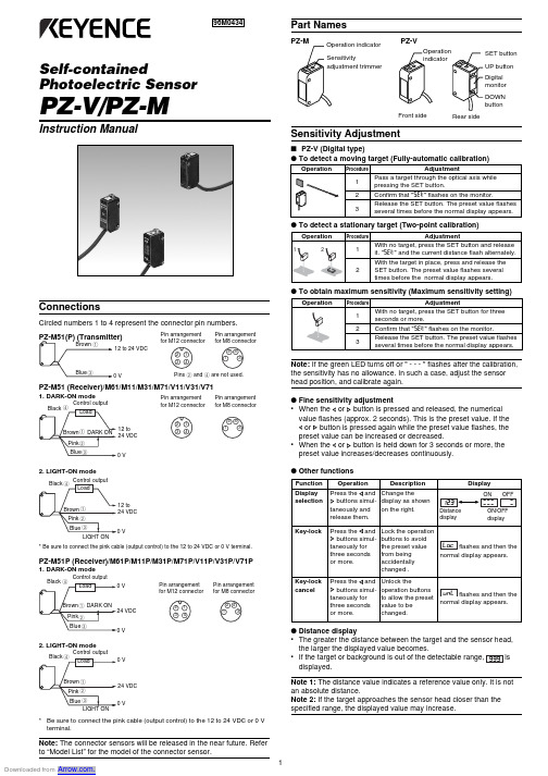
Self-containedPhotoelectric SensorPZ-V/PZ-MInstruction Manual96M0434ConnectionsCircled numbers 1 to 4 represent the connector pin numbers.PZ-M51 (Receiver)/M61/M11/M31/M71/V11/V31/V711. DARK-ON mode2. LIGHT-ON mode* Be sure to connect the pink cable (output control) to the 12 to 24 VDC or 0 V terminal.PZ-M51P (Receiver)/M61P/M11P/M31P/M71P/V11P/V31P/V71P1. DARK-ON mode2. LIGHT-ON mode*Be sure to connect the pink cable (output control) to the 12 to 24 VDC or 0 V terminal.Note: The connector sensors will be released in the near future. Refer to “Model List” for the model of the connector sensor.12 to 24 VDCControl output 12 to 24 VDC12 to 24 VDCControl output Control output24 VDC Pin arrangement for M12 connectorPin arrangement for M8 connectorPins 2 and 4 are not used.Pin arrangement for M12 connector Pin arrangement for M8 connectorPin arrangement for M12 connectorPin arrangement for M8 connectorPart NamesPZ-VSensitivity Adjustment■PZ-V (Digital type)●To detect a moving target (Fully-automatic calibration)●To obtain maximum sensitivity (Maximum sensitivity setting)Note: If the green LED turns off or " - - - " flashes after the calibration,the sensitivity has no allowance. In such a case, adjust the sensor head position, and calibrate again.●Fine sensitivity adjustment•When the or button is pressed and released, the numerical value flashes (approx. 2 seconds). This is the preset value. If the or button is pressed again while the preset value flashes, the preset value can be increased or decreased.•When theor button is held down for 3 seconds or more, the preset value increases/decreases continuously.●Other functions●Distance display•The greater the distance between the target and the sensor head,the larger the displayed value becomes.•displayed.Note 1: The distance value indicates a reference value only. It is not an absolute distance.Note 2: If the target approaches the sensor head closer than the specified range, the displayed value may increase.231421432314214323142143Rear sideSensitivity Adjustment■PZ-M (Trimmer type)•DARK-ON mode (When LIGHT-ON mode is selected, refer to the description in parentheses.)•LIGHT-ON mode (When DARK-ON mode is selected, refer to the* The adjustment for the retroreflective type is the same as for the thrubeam type.Mutual Interference•The alternate-frequency type allows mutual interference suppression up to two sensors.•The alternate-frequency type is not available for the thrubeam type.•To suppress the mutual interference with the thrubeam type or with three or more sensors, contact KEYENCE.Sensor Head OrientationTo detect a moving target, consider orientation of the sensor head according to the direction of the movement.directionCorrect CorrectSpecifications1. The alternate-frequency type is indicated by replacing "1" at the end of model name with "5". The models are PZ-M65, M15, M35, M75, V15 V35 and V75.2. The detecting distance is obtained with the maximum sensitivity.3. The transmitter of the PZ-M51 features a power indicator only.4. The PNP-output type sensor is suffixed with P after the model name.5. 3000 lux max for the PZ-M71P/V71P.Slit plateSlit width (mm)0.512Detecting distance (mm)50010002000Target size (mm)0.5 x 51 x 52 x 5e p y T m a e b u r h T e v i t c e lf e r o r t e R ev i t c e l f e r -i t l u M le d o M 15M -Z P 16M -Z P .111M -Z P .113M -Z P .117M -Z P .111V -Z P .113V -Z P .117V -Z P .1e c n a t s i d g n i t c e t e D .2m 01m 5.1o t 1.05-R n e h W ()d e s u s i r o t c e l f e r m m 001o t 5m c 01x 01()r e p a p e t i h w m m 003o t 5m c 01x 01()r e p a p e t i h w m m 009o t 02m c 03x 03()r e p a p e t i h w m m 001o t 5m c 01x 01()r e p a p e t i h w m m 003o t 5m c 01x 01()r e p a p e t i h w m m 009o t 02m c 03x 03()r e p a p e t i h w e c n a t s i d g n i t t e S ——m m 001o t 03m c 01x 01()r e p a p e t i h w m m 003o t 04m c 01x 01()r e p a p e t i h w m m 009o t 051m c 01x 01()r e p a p e t i h w m m 001o t 03m c 01x 01()r e p a p e t i h w m m 003o t 04m c 01x 01()r e p a p e t i h w mm 009o t 051mc 01x 01()r e p a p e t i h w ec r u o s t h g i L D E Lde R D E L d e r a rf n I D E L d e R D E L d e r a r f n I t n e m t s u j d a y t i v i t i s n e S )°032(r e m m i r t n r u t -1n o i t a r b i l a c c i t a m o t u A e m i t e s n o p s e R .x a m s m 5.1y l n o 56M h t i w .x a m s m 2,e p y t y c n e u q e r f -e t a n r e t l a h t i w .x a m s m 2.1(.x a m s m 1.1)e d o m n o i t a r e p O )g n i r i w y b e l b a t c e l e s (N O -K R A D /N O -T H G I L s r o t a c i d n I .3D E L n e e r G :n o i t a r e p o e l b a t S ,D E L e g n a r O :t u p t u O r o t i n o m l a t i g i D —DE L d e r t i g i d -3t n e m g e s -7t u p t u o l o r t n o C .x a m V 1e g a t l o v l a u d i s e R ,).x a m V 03(.x a m A m 001r o t c e l l o c -n e p o N P N r o t c e l l o c -n e p o P N P .4.x a m V 1e g a t l o v l a u d i s e R ,).x a m V 4.62(.x a m A m 001t i u c r i c e v i t c e t o r P eb r o s b a e g r u S ,n o i tc e t o r p t n e r r u c r e v O ,n o i t c e t o r p y t i r a l o pde s r e v e R y l p p u s r e w o P xa m %01)P -P (e l p p i R ,%01±C D V 42o t 21n o i t p m u s n o c t n e r r u C .x a m A m 42:T .x a m A m 72:R .x a m A m 43.x a m A m 03.x a m A m 83.x a m A m 73.x a m A m 54g n i t a r e r u s o l c n E 76-P I th g i l t n e i b m A e r u t a r e p m e t t n e i b m A gn i z e e r f o N ,)F °851o t 4-(C °55+o t 02-y t i d i m u h e v i t a l e R no i t a s n e d n o c o N ,%58o t 53n o i t a r b i V yl e v i t c e p s e r s r u o h 2,s n o i t c e r i d Z d n a Y ,X n i e d u t i l p m a e l b u o d m m 5.1,z H 55o t 01kc o h S s /m 00012hc a e s e m i t x i s ,s n o i t c e r id Z d n a Y ,X n i l a i re t a m g n i s u o H ni s e r d e c r o f n i e r r e b i f -s s a l G th g i e W )e l b a c m -2g n i d u l c n i (g 05.x o r p p A :T g55.x o r p p A :R g55.x o r p p A g07.x o r p p A g55.x o r p p A g07.x o r p p A Incandescent lamp: 5000 5.lux max., Sunlight: 20000 lux max■OptionsThe optional slit plate and polarizing filter are available for the PZ-M51 thrubeam type.Model: A-4 (A set of three types of slit plates and a polarizing filter.)Slit plate + Polarizing filter Slit width (mm)No slit 0.512Detectingdistance (mm)40002006001300Target size (mm)6 x 60.50 x 51 x 52 x 5Model ListCable type M8 connector typeM12 connector typeThrubeamPZ-M51PZ-M52PZ-M53RetrorefrectivePZ-M61PZ-M62PZ-M63100 mm DigitalPZ-V11PZ-V12PZ-V13Trimmer PZ-M11PZ-M12PZ-M13300 mmDigital PZ-V31PZ-V32PZ-V33Trimmer PZ-M31PZ-M32PZ-M33900 mmDigital PZ-V71PZ-V72PZ-V73TrimmerPZ-M71PZ-M72PZ-M73Multi-reflectiveIf you want to mount the sensor head in an orientation other than the above, contact KEYENCE.DimensionsReflector R-5(Accessory for PZ-M61only)PZ-V11/V31Special mounting bracket is optionally available. Contact KEYENCE for details.I/O CircuitCircled numbers 1 to 4 represent the connector pin numbers.PZ-M51(P) (Transmitter)PZ-M51 (Receiver)/M61/M11/M31/V11/V31PZ-M51P (Receiver)/M61P/M11P/M31P/V11P/V31PHints On Correct Use•To extend the cable length, use a cable with at least a 0.3 mm 2nominal cross-section area. Limit the length of cable extension to no more than 100 m.•If the amplifier cable is placed together with power lines or highvoltage lines in the same conduit, a detection error may occur due to noise interference, or the sensor may be damaged. Isolate the amplifier cable from these lines.•When using a commercially available switching regulator, ground the frame ground terminal and ground terminal.•Do not use the PZ-V/PZ-M series outdoors or in a place where extraneous light can enter the light-receiving surface directly.•When the multi-reflective type is used for the detection of a target with high reflectivity (e.g. mirror-surfaced object), proper detection or distance adjustment may be disabled. In such a case, tilt the sensor head at some angle.•During maximum sensitivity setting, the detecting distance may vary due to a difference in characteristics of each unit.KEYENCE CORPORATION1-3-14, Higashi-Nakajima, Higashi-Y odogawa-ku,Osaka, 533-8555, JapanPHONE: +81-6-6379-2211 FAX: +81-6-6379-2131AFFILIATED COMPANIESKEYENCE CORPORATION OF AMERICA PHONE: 201-930-0100 FAX: 201-930-0099KEYENCE DEUTSCHLAND GmbHPHONE: 06102-36 89-0 FAX: 06102-36 89-100KEYENCE (UK) LIMITEDPHONE: 01908-696900 FAX: 01908-696777KEYENCE FRANCE S.A.PHONE: 01 47 92 76 76 FAX: 01 47 92 76 77KEYENCE SINGAPORE PTE LTD.PHONE: 392-1011 FAX: 392-5055KEYENCE (MALAYSIA) SDN BHDPHONE: 03-252-2211 FAX: 03-252-2131KEYENCE (THAILAND) CO., LTD.PHONE: 02-369-2777 FAX: 02-369-2775KEYENCE TAIWAN CO., LTD.PHONE: 02-2627-3100 FAX: 02-2798-8925KEYENCE KOREA CORPORATIONPHONE: 02-563-1270 FAX: 02-563-1271© KEYENCE CORPORATION, 20000061-1 96M0434 Printed in Japan0V•Be sure to check that the wiring is properly established. Improper wiring may cause a decrease in sensitivity or overheating and sensor damage. (See “I/O Circuit”.)•To mount the sensor, use an M3 screw (coarse thread). Limit the tightening torque to 0.6 N•m or less.•To mount PZ-M71/V71, use an M4 screw (coarse thread). Limit the tightening torque to 0.7 N•m or less.•To attach the R-5 reflector, use an M3 screw (coarse thread). Limit the tightening torque to 0.3 N•m or less.•The displayed value may vary depending on the surrounding environment, such as temperature change or dust.•Use a stable power supply. The sensor cannot operate properly if the power supply is unstable at power-on or if the ripple exceeds the specified range.WARRANTIES (MUST ACCOMPANY THE PRODUCTS)KEYENCE, at its sole option, will refund, repair or replace at no charge any defective Products within 1 year from the date of shipment. Unless stated otherwise herein, the Products should not be used internally in humans, for human transportation, as safety devices or fail-safe systems. EXCEPT FOR THE FOREGOING, ALL EX-PRESS, IMPLIED AND STATUTORY WARRANTIES, INCLUDING WARRANTIES OF MERCHANTABILITY, FITNESS FOR A PARTICULAR PURPOSE AND NON-INFRINGEMENT OF PROPRIETARY RIGHTS, ARE EXPRESSLY DISCLAIMED.KEYENCE SHALL NOT BE LIABLE FOR ANY DIRECT, INDIRECT, INCIDENTAL,CONSEQUENTIAL OR OTHER DAMAGES, EVEN IF DAMAGES RESULT FROM THE USE OF THE PRODUCTS IN ACCORDANCE WITH ANY SUGGESTIONS OR INFORMATION PROVIDED BY KEYENCE. In some jurisdictions, some of the foregoing warranty disclaimers or damage limitations may not apply.M12 Connector type)。
W2

检测距离 0... 1.2m
对射式光电开关
完美的尺寸与性价比 坚固的外壳,加装了M3 金属安装孔
WS/WE 2纤细型对射式光电开关,红色光源
尺寸图
连接方式 WS/WE2S-E113 WS/WE2S-F113
安装孔Φ3.2mm LED信号指示灯 接收器光轴中心 发射器光轴中心
WS/WE2S-F213
检测和定位更加精准。 ■ 可靠精确地检测透明和高反射
率物体。
因空间狭小且要求安装精确而无法 安装光电开关仍然是仍感器面临的 越来越苛刻的挑战吗?W2系列光 电开关能在狭小的空间里安装且保 证对其定位准确的要求。 W2系列光电开关具有独有的外壳 构造,非常适合安装在狭小的空间 里去精确完成检测、定位等任务。 W2可以在长距离,强环境光,反 射率大的检测物体的条件下出色地 完成任务。
*)沿传感器轴的方向后置反射镜
订货资料 型号
WL2S-E111 WL2S-F111 WL2S-F211 WL2S-F411 WL2S-N111 WL2S-N111 WL2S-P111
订货号
1022667 1022666 1023868 1023644 1023870 1023869 1024249
工业传感器 61
防护等级 工作温度 储藏温度 重量 外壳材料 1)90%反射率物体(参考
DIN5033标准的白色) 2)在温度Ta=+25℃时,
平均工作寿命75.000小时 检测距离和信息冗余量
检测距离2…18mm
WT2F- N140 N170 P140 P170 P240 P270 P440
1...18mm1) 1...9mm1) 5...15mm1) 1...8mm1) PinPoint ,LED,红光 DC12……24V3) <5VPP4)