VICTOR 4105A使用说明1
胜利4105A接地仪表使用手册英文
Instruction Manual for Digital Grounding Resistance MeterInstruction Manual for DigitalGrounding Resistance MeterTable of ContentsI. Overview (2)II. Open-case Inspection (3)III. Safety Precautions (4)IV. Work Principle (7)V. Appearance Description (9)VI. Technical Characteristics (10)VII. Resistance Measurement Method..12 VIII.Battery Installation (20)IX.Troubleshooting (22)WarningThe warnings and safety requirements stated in this manual must be strictly observed to ensure safety. Please read the operating instructions carefully before using this meter.I.OverviewGrounding Resistance Meter, as a professional instrument for measurement of grounding resistance of electrical equipment, is made by improving the circuit, structure and technology of traditional ground resistance meter. Witha beautiful and practical fashion style, this meter will provide more complete function, higher accuracy and more convenient operation. Thanks to the dust-and-moisture proof structure, this meter is better suited to field operation. It is designed to measure the grounding resistance of grounding systems of a variety of power systems, electrical equipment and lightning protection equipment, and also to measure AC voltage.II.Open-case Inspection1.Grounding resistance meter1 set2.Canvas bag1 Pcs3.Ground drill rod2 Pcs4.Auxiliary testing wire1 set(including: a piece of 15-meter redwire, 10-meter yellow wire, and5-meter green wire)5.Simple testing wire1 set(including: a piece of 1.6-meter red wire and 1.6-meter green wire)6.5# alkaline battery (LR 6 AA) (1.5V)x 8 8 Pcs7.Instruction manual1 copy8.Strap1 pieceIII.Safety Precautions1. Please read this instruction manual carefully before using this grounding resistance meter2. Do not use the grounding resistance meter and measuring wire with damaged surface.3. Do not touch the conductor with a voltage of higher than DC 60V or AC36V RMS in order to prevent electric shock, since the said voltage has reached the standard of electric shock.4. Before the measurement of resistance, the tester must be completely isolatedwith power circuit in order to ensure accurate readings and personal safety.5. The meter shall not be stored at high temperature; direct sunlight shall be avoided so as not to affect the service life of LCD.6. When the symbol "" which indicates "low battery" appears, the battery shall be replaced. Before long-term storage, the batteries shall be taken out to prevent the damage to meter caused by battery leakage.7. Special care should be exercised during the measurement for bare wires. 8. The battery will be disconnected when an external adapter is used. In this case,the battery cannot be recharged. Note: please select the power supply mode () .9. Grounding resistance testing requirements:a. The AC grounding resistance shall not be greater than 4Ω;b. The safety grounding resistance shall not be greater than 4Ω;c. The DC grounding resistance shall be determined according to specific requirements of computer system;d. Lightning protection grounding resistance shall not be greater than 10Ω;e. For the joint grounding of shielding system, the grounding resistance shall not be greater than 1Ω;Warning!ResistanceHighVoltage!Dangerous!ACEarth Battery under-voltageDoubleinsulation CE compliedIV.Work PrincipleThe measuring principle of grounding resistance is based on the law of resistance. Insert 4 electrodes (E1, P1, P2, E2) to a certain depth under the ground, and the distance between electrodes shallbe around 20 meters. See the figure below:AC signals act on electrodes E1 and E2, and the current that flows through the earth shall be measured by ammeter through electrodes P1 and P2. If the current value is a constant, the measured voltage will be proportional to earth resistance. The displayed value depends on swamping resistance; hence, the appropriate range shall be determined according to measured resistance valuesin order to get the best readings. AC signal is generated by the built-in converter.V.Appearance Description1, 2, 3 and 4: Range selector switch (2 0Ω/200Ω/2000Ω/EARTH VOLTAGE). 5: Digital holding switch (HOLD)6: Power Switch: self-locking power switch (POWER)7: Testing indicator: this lamp goes on during the testing if the connection iscorrect.8: Test button.9: LCD: display measurement data and unit symbols.10: Instrument model11: P port: potential pole.12: C port: current pole.13: E port: grounding pole.14: ACV port: voltage pole.15: Power adapter jack ().VI.Technical Characteristics1. General features(1) Display: 84.8 ×59.8mmwindow-type LCD display;Maximum displayed value "1999".(2) Over-range indication: the firstdigit is "1" when the upper limit isexceeded.(3) Power supply: 5# alkaline batteryLR6 (1.5V) x 8 (can be connected tooptional adapter); under-voltageindication function is provided.(4)Power consumption:powerconsumption during no-load testing is≤800mw.(5) Operating environment: 0℃- 4 0℃.Relative humidity: 30% - 85%RH. (6) Overall dimensions: 175(L)×110(W)×70(D)mm(7)Weight: about 680g (includingbatteries).2. Technical data Grounding resistanceMeasuring rangeBasicaccuracyResolution20Ω ±(2%+0.1Ω)0.01Ω 200Ω 0.1Ω2000Ω ±(2%+3d)1ΩGrounding voltage (50Hz - 200Hz)Measuring range Basic accuracy Resolution InputimpedanceOverloadprotection200 V ±( 2.0 % + 6 d ) 0.1 V 1 MΩ 200V rms VII.Resistance Measurement Method7-1. Battery voltage inspectionAfter the startup, if the battery symbol is not indicated on the display, it means that the current power is sufficient. When the display flashes or shows this symbol, please replace the battery in accordance with instructions in Chapter VIII.7-2. Testing wire connectionPlease make sure the plug of testing lead has been completely inserted into the test side. The loose connection may lead to errors in the measurement results.7-3 Test methodDanger: an AC voltage of up to 50Vmay occur between E-C or E-P terminals during the measurement of grounding resistance. Do not touch test lead so as to avoid electric shock.7-3-1Conventional resistance measurement method1) Test lead connectionAs shown below, insert the auxiliary grounding rods P and C into the ground vertically at the point 5-10 meters from the grounded object, connect the green wire to instrument terminal E, the yellow one to terminal P, and the red one to terminal C.Note: Please insert the auxiliary grounding rod into the ground with highwater content. If the rod is to be inserted into dry ground, silica-containing ground or the ground with gravels, the ground shall be wetted with water in order to ensure that the grounding rod be inserted into wet ground. In case of cement ground, please apply water to the horizontally placed grounding rod, and cover it with wet towel before the measurement.2) Grounding voltage measurement Please set the range selector switch toEarth Voltage position. If the voltage value is displayed on the screen, it means there is grounding voltage in the system. Please check if the voltage value is lower than 10V. If the value is above 10V, an error of measured grounding resistance value may occur. In this case, please turn off the power supply of tested grounding device, and carry out the measurement after the grounding voltage drops.3) Grounding resistance measurement Start from the 2000Ωlevel, and press the "TEST" key. Backlight goes on to indicate that a test is in progress. If the displayed value is too small, you can change the level to 200Ω, 20Ω.... The displayed value under this circumstanceis the measured value of grounding resistance.Note: The symbol "" means the grounding impedance of auxiliary grounding rod C is too high. In this case, please check if the connection is loose, or increase the humidity of ground around the auxiliary grounding rod to reduce ground impedance.Note: Ensure that the wires are not entwined. If the testing wires are entwined with each other, the mutual induction may occur during the testing in "false connection" condition and will influence the readings. If the auxiliarygrounding impedance is too strong, an error of display value may occur. Ensure that the auxiliary grounding rods P and C are inserted into wet ground, and all the connection parts are in full contact.7-3-2. Simple grounding resistance measurement methodThis is a simple method for the places where insertion of auxiliary grounding rod is not available. For this method, a grounding electrode like metal water pipe, commercial electric power system common grounding terminal or structure grounding terminal, etc. with extremely weak grounding impedance is used instead of auxiliary grounding rods C and P. Please use simple test leads.1) Test lead connectionPlease connect the leads according to the figure below.Note: If the simple test leads supplied together with this instrument are not used, please make a short circuit for terminals C and P.2) Grounding voltage measurement Please set the range selector switch toEarth Voltage position. If the voltage value is displayed on the screen, it means there is grounding voltage in the system. Please check if the voltage value is lower than 10V. If the value is above 10V, an error of measured grounding resistance value may occur. In this case, please turn off the power supply of tested grounding device, and carry out the measurement after the grounding voltage drops.3) Grounding resistance measurement Start from the 2000Ωlevel. Please press the "TEST" button. The backlight goes on to indicate a test is in progress. If the displayed value is too small, please switch to the 200Ω/20Ωlevel. The value displayed in this case is thegrounding resistance value. Please turn off the power switch after the test is completed in order to save power. Note: ●The measured current is about 2mA. The circuit breaker will not be actuated even if a leakage circuit breaker is connected.●The real grounding resistancevalue RX is subject to thefollowing formula:RX = RE - rere: grounding resistance ofcommon ground terminal ofcommercial power systemetc.Re: instrument groundingresistance readingVIII.Battery InstallationWhen the battery power is low, a "" symbol will appear on the screen, which means the battery needs to be replaced. Turn off the instrument and take out the batteries.Unscrew the screws at battery door with a screwdriver.Open the battery door.Load a new battery (pay attention to polarity).Close the battery cover and tighten the screws.Step I Step II IX.TroubleshootingIf your meter can't operate properly, the following methods can help you quickly resolve general problems. If the faults are still not removed, please contact the service center or distributor.Symptom Check position andmethodNo display ● Power supply is notconnected;● Replace the battery.symboloccurs● Replace the battery. Big displayerror ●Replace the battery.This manual is subject to change without notice.The contents of this manual are considered correct. If you find some errors and omissions therein, please contact the manufacturer.We are not responsible for any accident and hazard due to user's faulty operation.The functions described in this manual cannot be taken as the reason for using this product for special purposes.601E-4105-000A。
接地电阻测试仪使用方法-20200402
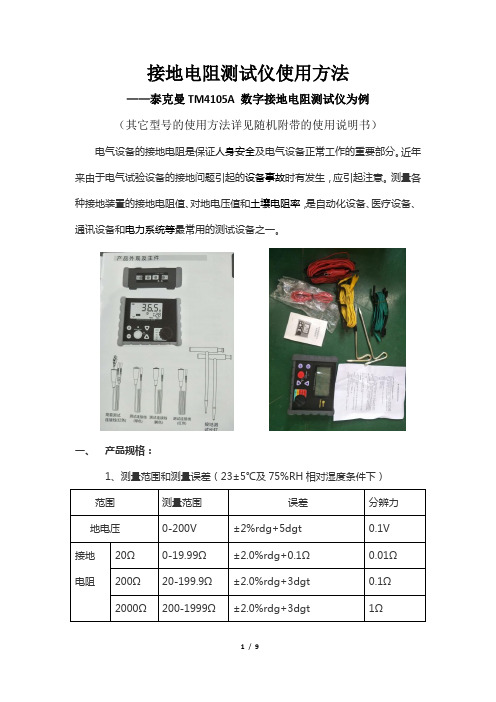
接地电阻测试仪使用方法——泰克曼TM4105A 数字接地电阻测试仪为例(其它型号的使用方法详见随机附带的使用说明书) 电气设备的接地电阻是保证人身安全及电气设备正常工作的重要部分。
近年来由于电气试验设备的接地问题引起的设备事故时有发生,应引起注意。
测量各种接地装置的接地电阻值、对地电压值和土壤电阻率,是自动化设备、医疗设备、通讯设备和电力系统等最常用的测试设备之一。
一、 产品规格:2、响应时间:测量接地电阻:大约5秒测量接地电压:大约2秒3、耐压:(电线对外壳)1500VAC,1分钟无跳火4、过载保护:地电阻档:200VAC (10秒)地电压档:300VAC (30秒)5、10分钟无操作自动关机6、接地电阻测量时间设定范围:10秒钟—10分钟7、供电电源:9V DC R6P (SUM-3)X6,6节1.5V的五号电池8、工作环境:温度:0~40℃相对湿度:≤85%RH(无雾)9、储存条件:温度:-20~60℃相对湿度:≤75%RH(无雾)二、危险提示、警告和注意:危险提示:1)不要在有易燃气体的环境下测试,使用本仪器的过程中可能会产生火花,若在有易燃气体的环境下测试可能会导致爆炸;2)当本仪器或使用者的手湿的时候请一定不要去连接测试棒;3)刚测试完后不要用手触摸本机测试线裸露部分,此时电路被存储了的电荷可能引起电击;待松开测试键,仪器自动释放测试产生的高压,高压指示灯灭,高压警报“滴、滴”声消失,待LCD屏幕显示“0V”时方可拆除测试线;4)本仪器进行地电阻功能测试时,在接线端E-C之间会产生最高约50V 的电压,可以造成对人的电击;5)当测地电阻时,不要施加电压给本机接线端子,已经连接的接地线需要断开;6)当进行地电压测试时,不要向测试端施加超过220V的电压,以免造成本机损坏。
必要时可将相关电气设备断电使地电压下降后再进行测量;7)不要施加超过本仪器的容许界限或测试范围的电量供应;8)当您正在测试时请不要打开电池盖。
胜利接地电阻测试仪VICTOR 4105A 说明书

胜利接地电阻测试仪VICTOR 4105A说明书目录一、概述 (1)二、开箱检查 (1)三、安全注意事项 (1)四、工作原理 (2)五、外观说明 (2)六、技术特性 (3)七、电阻测量方法 (3)八、电池安装 (5)九、故障排除 (5)警告本说明书包括警告和安全规格,必须严格遵守以确保安全,在使用本仪表之前请详细阅读操作说明。
一、概述VICTOR4105A接地电阻测试仪是一款专业测试电气设备接地电阻的仪器,对传统接地电阻测试仪的电路、结构、工艺进行了改良,再加上美观实用的新潮款式,使之功能更全,准确度更高,操作更方便可靠,防尘防潮的结构,更适合野外使用。
它可用于各种电力系统、电力设备、防雷设备等接地系统的接地电阻值,还可以测量交流电压。
二、开箱检查1、VICTOR4105A接地电阻表1台2、帆布袋1个3、接地钢钎2个4、辅助测试线(包括:红色15米一条,黄色10米一条,绿色5米一条)1套5、简易测试线(包括:红色1.6米一条,绿色1.6米一条)1套6、5#碱性电池(LR6 AA)(1.5V)×8 8只7、使用说明书1本8、产品合格证1份9、背带1根三、安全注意事项1、使用该接地电阻表前请认真阅读此安全使用说明书2、如果该接地电阻表或者测量线的外表有所破损,请勿使用。
3、请勿接触带电DC60V,AC36V RMS以上导体以免导致触电,此电压以达到触电标准。
4、测量电阻之前,必须与电源电路完全隔离,以保证读数准确及人生安全。
5、仪表不宜置于高温处存放,避免阳光直接照射以免影响液晶显示器的寿命。
6、电池,以免电池漏电损坏仪表。
7、 测量裸电线时,请务必特别要小心谨慎。
8、 当外接适配器供电时,会断开内部电池供电,此时不能对电池进行充电。
注意:请9、 接地电阻测试要求:a 、 交流工作接地,接地电阻不应大于4Ω;b 、 安全工作接地,接地电阻不应大于4Ω;c 、 直流工作接地,接地电阻应按计算机系统具体要求确定;d 、 防雷保护地的接地电阻不应大于10Ω;e 、 对于屏蔽系统如果采用联合接地时,接地电阻不应大于 Ω四、工作原理接地电阻测量原理是基于电阻定律。
小儒牛发球机使用说明

小儒牛发球机使用说明
小儒牛发球机使用说明:
1. 将小儒牛发球机放置在发球区域,并将其与电源插座连接。
2. 打开机器的电源开关,确保机器处于正常工作状态。
3. 调整发球机的发球速度和角度,根据您的需要进行调整。
通常情况下,可以通过机器上的按钮或旋钮进行调整。
4. 将足球或篮球等球类放入机器的球筒中。
请注意球类的大小和适应性,确保其适合发球机使用。
5. 确保发球机的发球口清洁,并没有任何障碍物阻挡发球。
6. 在准备好的位置站立并准备接球。
请注意安全,确保自己和他人远离发球区域。
7. 按下发球机上的发球按钮或触发器,机器将发射球类。
将准备好的姿势和动作用于接球。
8. 根据需要,您可以连续发球或单个发球。
请根据您的训练要求进行相应调整。
9. 使用完毕后,关闭电源开关,并将发球机存放在安全的地方。
请注意,具体的使用说明可能会因发球机型号和品牌而有所不同。
在使用发球机前,建议您仔细阅读并遵守机器提供的使用说明书。
另外,请一定注意安全,确保使用发球机的过程中没有造成任何人身伤害或损害。
胜利仪器VICTOR 4107A接地电阻测试仪_中文说明书
第一章简介警告使用仪器前,请仔细阅读使用说明书。
概述本仪器是一台智能型多功能接地电阻测试仪。
本仪器采用DSP处理器和数字信号处理技术,直接提取接地测量信号,具有高分辨率、高精度、很好的抗干扰能力等特点,可准确测量接地电阻值。
可快速、准确地测量接地的环境参数(干扰频率、干扰电压),分析接地测量噪声,然后选择一个能将其影响减到最小的测量频率。
本仪器还具有计算土壤电阻率功能。
●设计符合以下安全标准:IEC61010-1(CAT Ⅲ 600V、污染等级Ⅱ)IEC61010-2-031(手持探头的特殊要求)IEC61557-1,4,5,10(交流1000V和直流1500V以下低压配电系统电气安全)●基本测量功能4极/3极/2极法接地电阻测量土壤电阻率(ρ)测量交直流电压测量●接地电阻测量采用正弦交流激励测试,4种测试频率(94Hz、105Hz、111Hz、128Hz),可手动或自动选择,从而减低干扰源影响。
●测试信号频率自动控制(AFC)功能。
●辅助接地电阻测试功能测试并显示辅助接地电阻。
●辅助接地电阻上限警告显示功能由于辅助接地电阻高而可能无法正确测试时显示警告。
●电阻测量中自动量程,超量程显示OL。
●平稳化测试在干扰严重场合,测试结果的稳定性可通过平稳化(Smooth)处理而得到提高。
●干扰电压、干扰电流过高指示功能。
●串联干扰电压、频率测试功能。
串联干扰电压存在时自动判定交流、直流并显示该电压值和频率。
●大屏幕LCD显示。
●白色背光功能便于在阴暗光线下工作。
●过热指示功能。
●可去除测试线的剩余电阻(Rk)的设定功能。
●预编程限值,通过/ 不通过(PASS / FAIL)评价测量结果。
●可设定土壤电阻率测试时的辅助接地棒间隔,设置范围:1m~30m。
●具有可设定时间的自动背光关闭和自动电源关闭功能。
●内置实时时钟,可为记录和测量工作提供准确计时。
●操作方便的数据记录功能、查询记录数据,内部存储器可独立存储500个(组)测量数据。
胜利4105B接地电阻测试仪使用说明书

胜利仪器(VICTOR) 接地电阻测试仪VC4105B接地电阻表
产品型号:VICTOR 4105B操作方式:手动量程
产品名称:低电阻测试仪VICTOR 4105B显示位数:3 1/2位
产品分类:★低电阻测试仪体积大小:台式
详细介绍:
1、此数字式低电阻测试仪是新一代电工测试仪表,美观实用款式新潮;
2、功能全,准确度高,操作方便可靠,防尘防潮结构,更适合野外使用。
3、可用于测量各种电力系统、电气设备、防雷设备等接地系统的接地电阻值,还可以测量交流电压。
|基|本|功|能|
测量模式量程分辨力基本准确度
接地电阻10Ω0.01Ω±(2%+21Ω) 100Ω0.1Ω
±(2%+3dgt) 1000Ω1Ω
接地电压
(交流)
750V 1V ±(1%+10dgt) |一|般|特|征|
机身颜色机身-深灰
钳表尺寸175×110×70mm
机身重量约600g(含电池)
标准配件辅助接地棒2支,测试线1套(红色测试线15米/条,黄色测试线10米/条,绿色测试线5米/条),简易测试线1套(红色测试线1.6米/条,绿色测试线1.6米/条),1.5 V(R6AA)电池8节,使用说明书一本,合格证1张,帆布袋1个。
小太阳场强仪使用方法
数字电视场强仪检验证书富恒公司保证,本产品出厂之时达到公布标准,不存在任何材料和制造工艺方面的问题。
保修本仪器售出后保修一年,终身技术服务,本公司或代理商负责必要的调试、校对或检验工作,仪器经核准检验合格后装箱,发还给用户.用户的职责是:严格按照说明书来使用仪器,如果出现问题要维修请送往本公司或指定代理维修站。
一般来说在保修期内,一切非人为使用不当而出现的故障,由我公司免费维修。
对不正确的使用(包括用户附加的软件或接口)、及用户自行拆机,本公司将不予保修。
~I~小太阳仪器下列各项不属于保修范围:1.机内7.2V/1600mAH可充电电池。
2.由于机械外力(撞击、跌落等)造成面板、开关装置及机壳的变形损坏并涉及到内部器件的故障。
3.擅自拆开仪器试图修理。
特别提示:1.开机注意事项:开机时听到“嘀”声后再放开开关键,这个过程为对本机进行初始化过程(对高频头的保护功能)。
2.充电注意事项:为了保护仪器,延长电池的使用寿命,本公司仪器在程序上做了特殊的设计。
充电器在220V电源上插够8小时以后,充电器停止工作。
所以每次充电完毕,请一定要将充电器从电源上拔下来,保存好以备下次使用。
~II~数字电视场强仪3.注意当仪器长期停止使用时,应每隔半年充一次电,防止电池自放电报废。
~III~数字电视场强仪目录1.M S1701Q/M S1801Q数字电视场强仪一般性说明 (03)1.1简介 (03)1.2面板装置 (03)1.3熟悉本机 (06)2.M S1701Q/M S1801Q数字电视场强仪测量操作方法 (08)2.1开机 (08)2.2频道电平测量(模拟电视信号 (09)2.3数字频道平均功率测量(数字电视频道) (10)2.4Q A M数字频道M E R,B E R测量 (11)2.5伴音载波电平测量 (12)2.6频率电平测量 (14)2.7干线电压测量 (16)2.8音量的调节 (17)2.9斜率测量(双频道测量) (18)2.10载噪比测量 (19)2.11回传信号测量(M S1701C/M S1801C (21)3.系统设置 (22)3.1数字参数设置(Q A M,带宽,符号率) (22)4.关于仪器供电电源的说明 (25)5.技术资料 (27)附录:中国电视数字/模拟频道表 (31)小太阳仪器1、MS1701Q/MS1801Q数字电视场强仪一般性说明1.1简介MS1701Q/MS1801Q数字电视场强仪是专为CA TV有线电视工程安装检测人员设计的高性能测量仪器。
胜利4105B接地电阻测试仪使用说明书

胜利仪器(VICTOR) 接地电阻测试仪VC4105B接地电阻表
产品型号:VICTOR 4105B操作方式:手动量程
产品名称:低电阻测试仪VICTOR 4105B显示位数:3 1/2位
产品分类:★低电阻测试仪体积大小:台式
详细介绍:
1、此数字式低电阻测试仪是新一代电工测试仪表,美观实用款式新潮;
2、功能全,准确度高,操作方便可靠,防尘防潮结构,更适合野外使用。
3、可用于测量各种电力系统、电气设备、防雷设备等接地系统的接地电阻值,还可以测量交流电压。
|基|本|功|能|
测量模式量程分辨力基本准确度
接地电阻10Ω0.01Ω±(2%+21Ω) 100Ω0.1Ω
±(2%+3dgt) 1000Ω1Ω
接地电压
(交流)
750V 1V ±(1%+10dgt) |一|般|特|征|
机身颜色机身-深灰
钳表尺寸175×110×70mm
机身重量约600g(含电池)
标准配件辅助接地棒2支,测试线1套(红色测试线15米/条,黄色测试线10米/条,绿色测试线5米/条),简易测试线1套(红色测试线1.6米/条,绿色测试线1.6米/条),1.5V(R6AA)电池8节,使用说明书一本,合格证1张,帆布袋1个。
胜利4105B接地电阻测试仪使用说明书
胜利仪器(VICTOR) 接地电阻测试仪VC4105B接地电阻表
产品型号:VICTOR 4105B操作方式:手动量程
产品名称:低电阻测试仪VICTOR 4105B显示位数:3 1/2位
产品分类:★低电阻测试仪体积大小:台式
详细介绍:
1、此数字式低电阻测试仪是新一代电工测试仪表,美观实用款式新潮;
2、功能全,准确度高,操作方便可靠,防尘防潮结构,更适合野外使用。
3、可用于测量各种电力系统、电气设备、防雷设备等接地系统的接地电阻值,还可以测量交流电压。
|基|本|功|能|
测量模式量程分辨力基本准确度
接地电阻10Ω0.01Ω±(2%+21Ω) 100Ω0.1Ω
±(2%+3dgt) 1000Ω1Ω
接地电压
(交流)
750V 1V ±(1%+10dgt) |一|般|特|征|
机身颜色机身-深灰
钳表尺寸175×110×70mm
机身重量约600g(含电池)
标准配件辅助接地棒2支,测试线1套(红色测试线15米/条,黄色测试线10米/条,绿色测试线5米/条),简易测试线1套(红色测试线1.6米/条,绿色测试线1.6米/条),1.5V(R6AA)电池8节,使用说明书一本,合格证1张,帆布袋1个。
4105接地电阻测试仪使用说明书
9、修理前确认事项
z 即使电源打开也不显示“000”。 请打开电池盖确认是否安装干电池或电池极性方向是否错误。(参考 7 章)
购买时电池并未安装,请用户自行安装。 z 接地电压测量时显示“1…..”。
请确认是否输入过大。200V 以上时最上位数将点亮,若测量电压时显示“1….”,请立刻终止测量。超过 200V 可能会损 伤仪器。 z 无法测量接地电阻,显示“1..”。(精密测量) 辅助接地电阻过大导致额定电流无法通过。请进行以下步骤: 更换辅助接地棒的场所或插入更深。
注意 ● 使用测试线或探棒时请确认完全插入端口。 ● 使用后必须将量程开关设置为 OFF,长期不使用或储藏时,请取下电池。 ● 请勿将仪表暴露在阳光、高温、潮湿、露水的环境里。 ● 请勿使用研磨剂或有机溶剂进行清洗,必须使用中性洗剂或湿抹布清洗。 ● 仪器潮湿时请勿收藏,必须在其干燥后保存。
2
2、特点
本仪器是适用于配电线、室内配线,电气机械器具的接地电阻测试仪。同时配备适用于对地电压测量的对地电压量程。
⑴符合 IEC61557 的安全规格设计。 ⑵具有防尘、防水功能,按 IEC60529 标准进行设计、制造,适用于恶劣天气中的测量工作。 ⑶采用大型显示屏,便于读取数据。 ⑷使用简易测试探棒可进行简易测量。简易测试探棒采用可交换鳄口夹和测试棒的设计。 ⑸接地电阻测量时,具有简单检测辅助接地电阻是否在允许范围内或测试线是否存在断线等情况的功能,便于确定仪器是否处于正常
被测接地体
必须确认商用电源的 B 种接地面
使用商用电源接地
● 必须使用检电器确认商用电源的接地面。
危险
● 请勿使用本仪器确认商用电源的接地面。被测接地极未连接或仪器测试线的连接不正确时,即使通电也不会显示电压,