UNI-EMV_0407_D
NuMicro N9H30系列开发板用户手册说明书

NuMicro®FamilyArm® ARM926EJ-S BasedNuMaker-HMI-N9H30User ManualEvaluation Board for NuMicro® N9H30 SeriesNUMAKER-HMI-N9H30 USER MANUALThe information described in this document is the exclusive intellectual property ofNuvoton Technology Corporation and shall not be reproduced without permission from Nuvoton.Nuvoton is providing this document only for reference purposes of NuMicro microcontroller andmicroprocessor based system design. Nuvoton assumes no responsibility for errors or omissions.All data and specifications are subject to change without notice.For additional information or questions, please contact: Nuvoton Technology Corporation.Table of Contents1OVERVIEW (5)1.1Features (7)1.1.1NuMaker-N9H30 Main Board Features (7)1.1.2NuDesign-TFT-LCD7 Extension Board Features (7)1.2Supporting Resources (8)2NUMAKER-HMI-N9H30 HARDWARE CONFIGURATION (9)2.1NuMaker-N9H30 Board - Front View (9)2.2NuMaker-N9H30 Board - Rear View (14)2.3NuDesign-TFT-LCD7 - Front View (20)2.4NuDesign-TFT-LCD7 - Rear View (21)2.5NuMaker-N9H30 and NuDesign-TFT-LCD7 PCB Placement (22)3NUMAKER-N9H30 AND NUDESIGN-TFT-LCD7 SCHEMATICS (24)3.1NuMaker-N9H30 - GPIO List Circuit (24)3.2NuMaker-N9H30 - System Block Circuit (25)3.3NuMaker-N9H30 - Power Circuit (26)3.4NuMaker-N9H30 - N9H30F61IEC Circuit (27)3.5NuMaker-N9H30 - Setting, ICE, RS-232_0, Key Circuit (28)NUMAKER-HMI-N9H30 USER MANUAL3.6NuMaker-N9H30 - Memory Circuit (29)3.7NuMaker-N9H30 - I2S, I2C_0, RS-485_6 Circuit (30)3.8NuMaker-N9H30 - RS-232_2 Circuit (31)3.9NuMaker-N9H30 - LCD Circuit (32)3.10NuMaker-N9H30 - CMOS Sensor, I2C_1, CAN_0 Circuit (33)3.11NuMaker-N9H30 - RMII_0_PF Circuit (34)3.12NuMaker-N9H30 - RMII_1_PE Circuit (35)3.13NuMaker-N9H30 - USB Circuit (36)3.14NuDesign-TFT-LCD7 - TFT-LCD7 Circuit (37)4REVISION HISTORY (38)List of FiguresFigure 1-1 Front View of NuMaker-HMI-N9H30 Evaluation Board (5)Figure 1-2 Rear View of NuMaker-HMI-N9H30 Evaluation Board (6)Figure 2-1 Front View of NuMaker-N9H30 Board (9)Figure 2-2 Rear View of NuMaker-N9H30 Board (14)Figure 2-3 Front View of NuDesign-TFT-LCD7 Board (20)Figure 2-4 Rear View of NuDesign-TFT-LCD7 Board (21)Figure 2-5 Front View of NuMaker-N9H30 PCB Placement (22)Figure 2-6 Rear View of NuMaker-N9H30 PCB Placement (22)Figure 2-7 Front View of NuDesign-TFT-LCD7 PCB Placement (23)Figure 2-8 Rear View of NuDesign-TFT-LCD7 PCB Placement (23)Figure 3-1 GPIO List Circuit (24)Figure 3-2 System Block Circuit (25)Figure 3-3 Power Circuit (26)Figure 3-4 N9H30F61IEC Circuit (27)Figure 3-5 Setting, ICE, RS-232_0, Key Circuit (28)Figure 3-6 Memory Circuit (29)Figure 3-7 I2S, I2C_0, RS-486_6 Circuit (30)Figure 3-8 RS-232_2 Circuit (31)Figure 3-9 LCD Circuit (32)NUMAKER-HMI-N9H30 USER MANUAL Figure 3-10 CMOS Sensor, I2C_1, CAN_0 Circuit (33)Figure 3-11 RMII_0_PF Circuit (34)Figure 3-12 RMII_1_PE Circuit (35)Figure 3-13 USB Circuit (36)Figure 3-14 TFT-LCD7 Circuit (37)List of TablesTable 2-1 LCD Panel Combination Connector (CON8) Pin Function (11)Table 2-2 Three Sets of Indication LED Functions (12)Table 2-3 Six Sets of User SW, Key Matrix Functions (12)Table 2-4 CMOS Sensor Connector (CON10) Function (13)Table 2-5 JTAG ICE Interface (J2) Function (14)Table 2-6 Expand Port (CON7) Function (16)Table 2-7 UART0 (J3) Function (16)Table 2-8 UART2 (J6) Function (16)Table 2-9 RS-485_6 (SW6~8) Function (17)Table 2-10 Power on Setting (SW4) Function (17)Table 2-11 Power on Setting (S2) Function (17)Table 2-12 Power on Setting (S3) Function (17)Table 2-13 Power on Setting (S4) Function (17)Table 2-14 Power on Setting (S5) Function (17)Table 2-15 Power on Setting (S7/S6) Function (18)Table 2-16 Power on Setting (S9/S8) Function (18)Table 2-17 CMOS Sensor Connector (CON9) Function (19)Table 2-18 CAN_0 (SW9~10) Function (19)NUMAKER-HMI-N9H30 USER MANUAL1 OVERVIEWThe NuMaker-HMI-N9H30 is an evaluation board for GUI application development. The NuMaker-HMI-N9H30 consists of two parts: a NuMaker-N9H30 main board and a NuDesign-TFT-LCD7 extensionboard. The NuMaker-HMI-N9H30 is designed for project evaluation, prototype development andvalidation with HMI (Human Machine Interface) function.The NuMaker-HMI-N9H30 integrates touchscreen display, voice input/output, rich serial port serviceand I/O interface, providing multiple external storage methods.The NuDesign-TFT-LCD7 can be plugged into the main board via the DIN_32x2 extension connector.The NuDesign-TFT-LCD7 includes one 7” LCD which the resolution is 800x480 with RGB-24bits andembedded the 4-wires resistive type touch panel.Figure 1-1 Front View of NuMaker-HMI-N9H30 Evaluation BoardNUMAKER-HMI-N9H30 USER MANUAL Figure 1-2 Rear View of NuMaker-HMI-N9H30 Evaluation Board1.1 Features1.1.1 NuMaker-N9H30 Main Board Features●N9H30F61IEC chip: LQFP216 pin MCP package with DDR (64 MB)●SPI Flash using W25Q256JVEQ (32 MB) booting with quad mode or storage memory●NAND Flash using W29N01HVSINA (128 MB) booting or storage memory●One Micro-SD/TF card slot served either as a SD memory card for data storage or SDIO(Wi-Fi) device●Two sets of COM ports:–One DB9 RS-232 port with UART_0 used 75C3232E transceiver chip can be servedfor function debug and system development.–One DB9 RS-232 port with UART_2 used 75C3232E transceiver chip for userapplication●22 GPIO expansion ports, including seven sets of UART functions●JTAG interface provided for software development●Microphone input and Earphone/Speaker output with 24-bit stereo audio codec(NAU88C22) for I2S interfaces●Six sets of user-configurable push button keys●Three sets of LEDs for status indication●Provides SN65HVD230 transceiver chip for CAN bus communication●Provides MAX3485 transceiver chip for RS-485 device connection●One buzzer device for program applicationNUMAKER-HMI-N9H30 USER MANUAL●Two sets of RJ45 ports with Ethernet 10/100 Mbps MAC used IP101GR PHY chip●USB_0 that can be used as Device/HOST and USB_1 that can be used as HOSTsupports pen drives, keyboards, mouse and printers●Provides over-voltage and over current protection used APL3211A chip●Retain RTC battery socket for CR2032 type and ADC0 detect battery voltage●System power could be supplied by DC-5V adaptor or USB VBUS1.1.2 NuDesign-TFT-LCD7 Extension Board Features●7” resolution 800x480 4-wire resistive touch panel for 24-bits RGB888 interface●DIN_32x2 extension connector1.2 Supporting ResourcesFor sample codes and introduction about NuMaker-N9H30, please refer to N9H30 BSP:https:///products/gui-solution/gui-platform/numaker-hmi-n9h30/?group=Software&tab=2Visit NuForum for further discussion about the NuMaker-HMI-N9H30:/viewforum.php?f=31 NUMAKER-HMI-N9H30 USER MANUALNUMAKER-HMI-N9H30 USER MANUAL2 NUMAKER-HMI-N9H30 HARDWARE CONFIGURATION2.1 NuMaker-N9H30 Board - Front View Combination Connector (CON8)6 set User SWs (K1~6)3set Indication LEDs (LED1~3)Power Supply Switch (SW_POWER1)Audio Codec(U10)Microphone(M1)NAND Flash(U9)RS-232 Transceiver(U6, U12)RS-485 Transceiver(U11)CAN Transceiver (U13)Figure 2-1 Front View of NuMaker-N9H30 BoardFigure 2-1 shows the main components and connectors from the front side of NuMaker-N9H30 board. The following lists components and connectors from the front view:NuMaker-N9H30 board and NuDesign-TFT-LCD7 board combination connector (CON8). This panel connector supports 4-/5-wire resistive touch or capacitance touch panel for 24-bits RGB888 interface.Connector GPIO pin of N9H30 FunctionCON8.1 - Power 3.3VCON8.2 - Power 3.3VCON8.3 GPD7 LCD_CSCON8.4 GPH3 LCD_BLENCON8.5 GPG9 LCD_DENCON8.7 GPG7 LCD_HSYNCCON8.8 GPG6 LCD_CLKCON8.9 GPD15 LCD_D23(R7)CON8.10 GPD14 LCD_D22(R6)CON8.11 GPD13 LCD_D21(R5)CON8.12 GPD12 LCD_D20(R4)CON8.13 GPD11 LCD_D19(R3)CON8.14 GPD10 LCD_D18(R2)CON8.15 GPD9 LCD_D17(R1)CON8.16 GPD8 LCD_D16(R0)CON8.17 GPA15 LCD_D15(G7)CON8.18 GPA14 LCD_D14(G6)CON8.19 GPA13 LCD_D13(G5)CON8.20 GPA12 LCD_D12(G4)CON8.21 GPA11 LCD_D11(G3)CON8.22 GPA10 LCD_D10(G2)CON8.23 GPA9 LCD_D9(G1) NUMAKER-HMI-N9H30 USER MANUALCON8.24 GPA8 LCD_D8(G0)CON8.25 GPA7 LCD_D7(B7)CON8.26 GPA6 LCD_D6(B6)CON8.27 GPA5 LCD_D5(B5)CON8.28 GPA4 LCD_D4(B4)CON8.29 GPA3 LCD_D3(B3)CON8.30 GPA2 LCD_D2(B2)CON8.31 GPA1 LCD_D1(B1)CON8.32 GPA0 LCD_D0(B0)CON8.33 - -CON8.34 - -CON8.35 - -CON8.36 - -CON8.37 GPB2 LCD_PWMCON8.39 - VSSCON8.40 - VSSCON8.41 ADC7 XPCON8.42 ADC3 VsenCON8.43 ADC6 XMCON8.44 ADC4 YMCON8.45 - -CON8.46 ADC5 YPCON8.47 - VSSCON8.48 - VSSCON8.49 GPG0 I2C0_CCON8.50 GPG1 I2C0_DCON8.51 GPG5 TOUCH_INTCON8.52 - -CON8.53 - -CON8.54 - -CON8.55 - -NUMAKER-HMI-N9H30 USER MANUAL CON8.56 - -CON8.57 - -CON8.58 - -CON8.59 - VSSCON8.60 - VSSCON8.61 - -CON8.62 - -CON8.63 - Power 5VCON8.64 - Power 5VTable 2-1 LCD Panel Combination Connector (CON8) Pin Function●Power supply switch (SW_POWER1): System will be powered on if the SW_POWER1button is pressed●Three sets of indication LEDs:LED Color DescriptionsLED1 Red The system power will beterminated and LED1 lightingwhen the input voltage exceeds5.7V or the current exceeds 2A.LED2 Green Power normal state.LED3 Green Controlled by GPH2 pin Table 2-2 Three Sets of Indication LED Functions●Six sets of user SW, Key Matrix for user definitionKey GPIO pin of N9H30 FunctionK1 GPF10 Row0 GPB4 Col0K2 GPF10 Row0 GPB5 Col1K3 GPE15 Row1 GPB4 Col0K4 GPE15 Row1 GPB5 Col1K5 GPE14 Row2 GPB4 Col0K6GPE14 Row2GPB5 Col1 Table 2-3 Six Sets of User SW, Key Matrix Functions●NAND Flash (128 MB) with Winbond W29N01HVS1NA (U9)●Microphone (M1): Through Nuvoton NAU88C22 chip sound input●Audio CODEC chip (U10): Nuvoton NAU88C22 chip connected to N9H30 using I2Sinterface–SW6/SW7/SW8: 1-2 short for RS-485_6 function and connected to 2P terminal (CON5and J5)–SW6/SW7/SW8: 2-3 short for I2S function and connected to NAU88C22 (U10).●CMOS Sensor connector (CON10, SW9~10)–SW9~10: 1-2 short for CAN_0 function and connected to 2P terminal (CON11)–SW9~10: 2-3 short for CMOS sensor function and connected to CMOS sensorconnector (CON10)Connector GPIO pin of N9H30 FunctionCON10.1 - VSSCON10.2 - VSSNUMAKER-HMI-N9H30 USER MANUALCON10.3 - Power 3.3VCON10.4 - Power 3.3VCON10.5 - -CON10.6 - -CON10.7 GPI4 S_PCLKCON10.8 GPI3 S_CLKCON10.9 GPI8 S_D0CON10.10 GPI9 S_D1CON10.11 GPI10 S_D2CON10.12 GPI11 S_D3CON10.13 GPI12 S_D4CON10.14 GPI13 S_D5CON10.15 GPI14 S_D6CON10.16 GPI15 S_D7CON10.17 GPI6 S_VSYNCCON10.18 GPI5 S_HSYNCCON10.19 GPI0 S_PWDNNUMAKER-HMI-N9H30 USER MANUAL CON10.20 GPI7 S_nRSTCON10.21 GPG2 I2C1_CCON10.22 GPG3 I2C1_DCON10.23 - VSSCON10.24 - VSSTable 2-4 CMOS Sensor Connector (CON10) FunctionNUMAKER-HMI-N9H30 USER MANUAL2.2NuMaker-N9H30 Board - Rear View5V In (CON1)RS-232 DB9 (CON2,CON6)Expand Port (CON7)Speaker Output (J4)Earphone Output (CON4)Buzzer (BZ1)System ResetSW (SW5)SPI Flash (U7,U8)JTAG ICE (J2)Power ProtectionIC (U1)N9H30F61IEC (U5)Micro SD Slot (CON3)RJ45 (CON12, CON13)USB1 HOST (CON15)USB0 Device/Host (CON14)CAN_0 Terminal (CON11)CMOS Sensor Connector (CON9)Power On Setting(SW4, S2~S9)RS-485_6 Terminal (CON5)RTC Battery(BT1)RMII PHY (U14,U16)Figure 2-2 Rear View of NuMaker-N9H30 BoardFigure 2-2 shows the main components and connectors from the rear side of NuMaker-N9H30 board. The following lists components and connectors from the rear view:● +5V In (CON1): Power adaptor 5V input ●JTAG ICE interface (J2) ConnectorGPIO pin of N9H30Function J2.1 - Power 3.3V J2.2 GPJ4 nTRST J2.3 GPJ2 TDI J2.4 GPJ1 TMS J2.5 GPJ0 TCK J2.6 - VSS J2.7 GPJ3 TD0 J2.8-RESETTable 2-5 JTAG ICE Interface (J2) Function●SPI Flash (32 MB) with Winbond W25Q256JVEQ (U7); only one (U7 or U8) SPI Flashcan be used●System Reset (SW5): System will be reset if the SW5 button is pressed●Buzzer (BZ1): Control by GPB3 pin of N9H30●Speaker output (J4): Through the NAU88C22 chip sound output●Earphone output (CON4): Through the NAU88C22 chip sound output●Expand port for user use (CON7):Connector GPIO pin of N9H30 FunctionCON7.1 - Power 3.3VCON7.2 - Power 3.3VCON7.3 GPE12 UART3_TXDCON7.4 GPH4 UART1_TXDCON7.5 GPE13 UART3_RXDCON7.6 GPH5 UART1_RXDCON7.7 GPB0 UART5_TXDCON7.8 GPH6 UART1_RTSCON7.9 GPB1 UART5_RXDCON7.10 GPH7 UART1_CTSCON7.11 GPI1 UART7_TXDNUMAKER-HMI-N9H30 USER MANUAL CON7.12 GPH8 UART4_TXDCON7.13 GPI2 UART7_RXDCON7.14 GPH9 UART4_RXDCON7.15 - -CON7.16 GPH10 UART4_RTSCON7.17 - -CON7.18 GPH11 UART4_CTSCON7.19 - VSSCON7.20 - VSSCON7.21 GPB12 UART10_TXDCON7.22 GPH12 UART8_TXDCON7.23 GPB13 UART10_RXDCON7.24 GPH13 UART8_RXDCON7.25 GPB14 UART10_RTSCON7.26 GPH14 UART8_RTSCON7.27 GPB15 UART10_CTSCON7.28 GPH15 UART8_CTSCON7.29 - Power 5VCON7.30 - Power 5VTable 2-6 Expand Port (CON7) Function●UART0 selection (CON2, J3):–RS-232_0 function and connected to DB9 female (CON2) for debug message output.–GPE0/GPE1 connected to 2P terminal (J3).Connector GPIO pin of N9H30 Function J3.1 GPE1 UART0_RXDJ3.2 GPE0 UART0_TXDTable 2-7 UART0 (J3) Function●UART2 selection (CON6, J6):–RS-232_2 function and connected to DB9 female (CON6) for debug message output –GPF11~14 connected to 4P terminal (J6)Connector GPIO pin of N9H30 Function J6.1 GPF11 UART2_TXDJ6.2 GPF12 UART2_RXDJ6.3 GPF13 UART2_RTSJ6.4 GPF14 UART2_CTSTable 2-8 UART2 (J6) Function●RS-485_6 selection (CON5, J5, SW6~8):–SW6~8: 1-2 short for RS-485_6 function and connected to 2P terminal (CON5 and J5) –SW6~8: 2-3 short for I2S function and connected to NAU88C22 (U10)Connector GPIO pin of N9H30 FunctionSW6:1-2 shortGPG11 RS-485_6_DISW6:2-3 short I2S_DOSW7:1-2 shortGPG12 RS-485_6_ROSW7:2-3 short I2S_DISW8:1-2 shortGPG13 RS-485_6_ENBSW8:2-3 short I2S_BCLKNUMAKER-HMI-N9H30 USER MANUALTable 2-9 RS-485_6 (SW6~8) FunctionPower on setting (SW4, S2~9).SW State FunctionSW4.2/SW4.1 ON/ON Boot from USB SW4.2/SW4.1 ON/OFF Boot from eMMC SW4.2/SW4.1 OFF/ON Boot from NAND Flash SW4.2/SW4.1 OFF/OFF Boot from SPI Flash Table 2-10 Power on Setting (SW4) FunctionSW State FunctionS2 Short System clock from 12MHzcrystalS2 Open System clock from UPLL output Table 2-11 Power on Setting (S2) FunctionSW State FunctionS3 Short Watchdog Timer OFFS3 Open Watchdog Timer ON Table 2-12 Power on Setting (S3) FunctionSW State FunctionS4 Short GPJ[4:0] used as GPIO pinS4Open GPJ[4:0] used as JTAG ICEinterfaceTable 2-13 Power on Setting (S4) FunctionSW State FunctionS5 Short UART0 debug message ONS5 Open UART0 debug message OFFTable 2-14 Power on Setting (S5) FunctionSW State FunctionS7/S6 Short/Short NAND Flash page size 2KBS7/S6 Short/Open NAND Flash page size 4KBS7/S6 Open/Short NAND Flash page size 8KBNUMAKER-HMI-N9H30 USER MANUALS7/S6 Open/Open IgnoreTable 2-15 Power on Setting (S7/S6) FunctionSW State FunctionS9/S8 Short/Short NAND Flash ECC type BCH T12S9/S8 Short/Open NAND Flash ECC type BCH T15S9/S8 Open/Short NAND Flash ECC type BCH T24S9/S8 Open/Open IgnoreTable 2-16 Power on Setting (S9/S8) FunctionCMOS Sensor connector (CON9, SW9~10)–SW9~10: 1-2 short for CAN_0 function and connected to 2P terminal (CON11).–SW9~10: 2-3 short for CMOS sensor function and connected to CMOS sensorconnector (CON9).Connector GPIO pin of N9H30 FunctionCON9.1 - VSSCON9.2 - VSSCON9.3 - Power 3.3VCON9.4 - Power 3.3V NUMAKER-HMI-N9H30 USER MANUALCON9.5 - -CON9.6 - -CON9.7 GPI4 S_PCLKCON9.8 GPI3 S_CLKCON9.9 GPI8 S_D0CON9.10 GPI9 S_D1CON9.11 GPI10 S_D2CON9.12 GPI11 S_D3CON9.13 GPI12 S_D4CON9.14 GPI13 S_D5CON9.15 GPI14 S_D6CON9.16 GPI15 S_D7CON9.17 GPI6 S_VSYNCCON9.18 GPI5 S_HSYNCCON9.19 GPI0 S_PWDNCON9.20 GPI7 S_nRSTCON9.21 GPG2 I2C1_CCON9.22 GPG3 I2C1_DCON9.23 - VSSCON9.24 - VSSTable 2-17 CMOS Sensor Connector (CON9) Function●CAN_0 Selection (CON11, SW9~10):–SW9~10: 1-2 short for CAN_0 function and connected to 2P terminal (CON11) –SW9~10: 2-3 short for CMOS sensor function and connected to CMOS sensor connector (CON9, CON10)SW GPIO pin of N9H30 FunctionSW9:1-2 shortGPI3 CAN_0_RXDSW9:2-3 short S_CLKSW10:1-2 shortGPI4 CAN_0_TXDSW10:2-3 short S_PCLKTable 2-18 CAN_0 (SW9~10) Function●USB0 Device/HOST Micro-AB connector (CON14), where CON14 pin4 ID=1 is Device,ID=0 is HOST●USB1 for USB HOST with Type-A connector (CON15)●RJ45_0 connector with LED indicator (CON12), RMII PHY with IP101GR (U14)●RJ45_1 connector with LED indicator (CON13), RMII PHY with IP101GR (U16)●Micro-SD/TF card slot (CON3)●SOC CPU: Nuvoton N9H30F61IEC (U5)●Battery power for RTC 3.3V powered (BT1, J1), can detect voltage by ADC0●RTC power has 3 sources:–Share with 3.3V I/O power–Battery socket for CR2032 (BT1)–External connector (J1)●Board version 2.1NUMAKER-HMI-N9H30 USER MANUAL2.3 NuDesign-TFT-LCD7 -Front ViewFigure 2-3 Front View of NuDesign-TFT-LCD7 BoardFigure 2-3 shows the main components and connectors from the Front side of NuDesign-TFT-LCD7board.7” resolution 800x480 4-W resistive touch panel for 24-bits RGB888 interface2.4 NuDesign-TFT-LCD7 -Rear ViewFigure 2-4 Rear View of NuDesign-TFT-LCD7 BoardFigure 2-4 shows the main components and connectors from the rear side of NuDesign-TFT-LCD7board.NuMaker-N9H30 and NuDesign-TFT-LCD7 combination connector (CON1).NUMAKER-HMI-N9H30 USER MANUAL 2.5 NuMaker-N9H30 and NuDesign-TFT-LCD7 PCB PlacementFigure 2-5 Front View of NuMaker-N9H30 PCB PlacementFigure 2-6 Rear View of NuMaker-N9H30 PCB PlacementNUMAKER-HMI-N9H30 USER MANUALFigure 2-7 Front View of NuDesign-TFT-LCD7 PCB PlacementFigure 2-8 Rear View of NuDesign-TFT-LCD7 PCB Placement3 NUMAKER-N9H30 AND NUDESIGN-TFT-LCD7 SCHEMATICS3.1 NuMaker-N9H30 - GPIO List CircuitFigure 3-1 shows the N9H30F61IEC GPIO list circuit.Figure 3-1 GPIO List Circuit NUMAKER-HMI-N9H30 USER MANUAL3.2 NuMaker-N9H30 - System Block CircuitFigure 3-2 shows the System Block Circuit.NUMAKER-HMI-N9H30 USER MANUALFigure 3-2 System Block Circuit3.3 NuMaker-N9H30 - Power CircuitFigure 3-3 shows the Power Circuit.NUMAKER-HMI-N9H30 USER MANUALFigure 3-3 Power Circuit3.4 NuMaker-N9H30 - N9H30F61IEC CircuitFigure 3-4 shows the N9H30F61IEC Circuit.Figure 3-4 N9H30F61IEC CircuitNUMAKER-HMI-N9H30 USER MANUAL3.5 NuMaker-N9H30 - Setting, ICE, RS-232_0, Key CircuitFigure 3-5 shows the Setting, ICE, RS-232_0, Key Circuit.NUMAKER-HMI-N9H30 USER MANUALFigure 3-5 Setting, ICE, RS-232_0, Key Circuit3.6 NuMaker-N9H30 - Memory CircuitFigure 3-6 shows the Memory Circuit.NUMAKER-HMI-N9H30 USER MANUALFigure 3-6 Memory Circuit3.7 NuMaker-N9H30 - I2S, I2C_0, RS-485_6 CircuitFigure 3-7 shows the I2S, I2C_0, RS-486_6 Circuit.NUMAKER-HMI-N9H30 USER MANUALFigure 3-7 I2S, I2C_0, RS-486_6 Circuit3.8 NuMaker-N9H30 - RS-232_2 CircuitFigure 3-8 shows the RS-232_2 Circuit.NUMAKER-HMI-N9H30 USER MANUALFigure 3-8 RS-232_2 Circuit3.9 NuMaker-N9H30 - LCD CircuitFigure 3-9 shows the LCD Circuit.NUMAKER-HMI-N9H30 USER MANUALFigure 3-9 LCD Circuit3.10 NuMaker-N9H30 - CMOS Sensor, I2C_1, CAN_0 CircuitFigure 3-10 shows the CMOS Sensor,I2C_1, CAN_0 Circuit.NUMAKER-HMI-N9H30 USER MANUALFigure 3-10 CMOS Sensor, I2C_1, CAN_0 Circuit3.11 NuMaker-N9H30 - RMII_0_PF CircuitFigure 3-11 shows the RMII_0_RF Circuit.NUMAKER-HMI-N9H30 USER MANUALFigure 3-11 RMII_0_PF Circuit3.12 NuMaker-N9H30 - RMII_1_PE CircuitFigure 3-12 shows the RMII_1_PE Circuit.NUMAKER-HMI-N9H30 USER MANUALFigure 3-12 RMII_1_PE Circuit3.13 NuMaker-N9H30 - USB CircuitFigure 3-13 shows the USB Circuit.NUMAKER-HMI-N9H30 USER MANUALFigure 3-13 USB Circuit3.14 NuDesign-TFT-LCD7 - TFT-LCD7 CircuitFigure 3-14 shows the TFT-LCD7 Circuit.Figure 3-14 TFT-LCD7 CircuitNUMAKER-HMI-N9H30 USER MANUAL4 REVISION HISTORYDate Revision Description2022.03.24 1.00 Initial version NUMAKER-HMI-N9H30 USER MANUALNUMAKER-HMI-N9H30 USER MANUALImportant NoticeNuvoton Products are neither intended nor warranted for usage in systems or equipment, anymalfunction or failure of which may cause loss of human life, bodily injury or severe propertydamage. Such applications are deemed, “Insecure Usage”.Insecure usage includes, but is not limited to: equipment for surgical implementation, atomicenergy control instruments, airplane or spaceship instruments, the control or operation ofdynamic, brake or safety systems designed for vehicular use, traffic signal instruments, all typesof safety devices, and other applications intended to support or sustain life.All Insecure Usage shall be made at customer’s risk, and in the event that third parties lay claimsto Nuvoton as a result of customer’s Insecure Usage, custome r shall indemnify the damagesand liabilities thus incurred by Nuvoton.。
艾默生CT-Unidrive M400中文彩页

• 电机运行时非常安静,PWM 载波频率高达 16 kHz。
电机控制模式包括:
控制模式
感应电机开环矢量或 V/F 控制
增强的感应 电机开环 转子磁通控制 (RFC-A)
功能
针对感应电机的开环电机控制,可提供良好的性能,配置简单。 可在多电机系统中使用 V/F 模 式。
• 尺寸兼容 • 板载编程 • 额定功率扩展至高达 110 kW (150 hp) • 支持 Commander SK 参数文件的导入和驱动器复制 典型应用: 实现对输送带、正排量泵、物料传输和切割以及木材加工等的 速度控制,这些应用中需要快速设置和诊断。
5
由 CODESYS 驱动的 Machine Control Studio 编程软件
常规表面和导轨安装 (仅 1 型和 2 型提供导 轨安装)
容易操作的控制接线 容易断开的内置 EMC 滤波器*
容易操作的电源接线*
稳固的电缆管理系统为控制电 缆和电源电缆屏蔽提供接地点
典型系统集成 (SI) 选件模块 * 在某些型号驱动器上,功能和位置有所变化
适用于可选通讯和扩展 I/O 的系统集成 (SI) 模块插槽
通过一种先进的矢量算法实现高性能速度和转矩控制,利用电流反馈大幅提高所有型号感应电机 的性能,无需反馈设备。
7
❯ ❯
❯ ❯
Unidrive M400 的选件选择与 端子布局
控制模式
1. 感应电机开环矢量或 V/F 控制 2. 感应电机开环转子磁通控制 (RFC-A)
可轻松访问机器控制功能
我们的软件工具、键盘和存储设备可供轻松快捷地访问 Unidrive M 的机器控制功能,以便配置、监控和诊断。
Unidrive M700

CONTROL TECHNIQUES
UNIDRIVE
M700
CAUTION Risk of Electric Shock STORED CHARGE 10 min More than one disconnect switch may be required to de-energise this equipment. Wait 10 minutes after powering down before accessing terminals.
CONTROL TECHNIQUES
➮ 250μs 循环时间 ➮ 运动曲线生成器 ➮ 电子齿轮 ➮ CAM 插补 ➮ 寻原点功能 ➮ 高速位置捕捉 • 高性能 MCi200 和 MCi210 机器控制模块(有助于获取更多的 控制性能)
Unidrive M700 的板载实时以太网(使用 IEEE 1588 V2)通过快速灵活的通信改善了机器控 制。可在 1 µs 内于整个网络中实现同步,数 据更新率可快达 250 µs (具有几乎无限的节 点数)。
Control Techniques 智能机器架构是一种实现自动化的开放式方 法,旨在实现机器最高生产率。这可以通过由开放式且全球可用 的工业标准以太网连在一起的智能控制设备、传感器与执行器组 成的同步高性能网络来实现。开放式标准可为机器制造者和 OEM 带来巨大效益:
• 每个机器组件均可选择“同级最优”的产品 • 熟悉的标准加快了机器开发和创新的速度 • 广泛接受的开放式标准有利于招聘具备所需专业知识的熟练工
最大限度地减少延迟 服务质量 (QoS) • 提供优先处理时间关键信息的方法。 • 进入交换机的信息将根据它们的标记优先级按顺序排列。
ᎁሌࣩ
7
6
Motorola 3.5 kHz 产品说明书
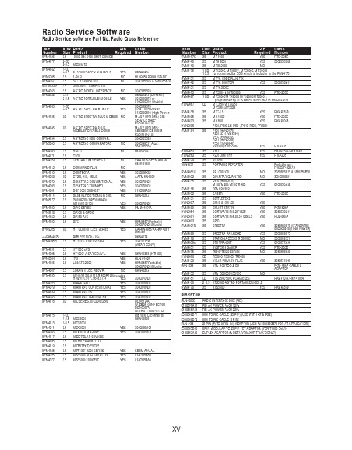
RVN4126 3.59100-386-9100-386/T DEVICERVN41772-CD2-3.5MCS/MTSRVN41821-CD2-3.5XTS3000/SABER PORTABLE YES RKN4046KHVN9085 3.51-20 R NO HLN9359 PROG. STAND RVN4057 3.532 X 8 CODEPLUG NO3080385B23 & 5880385B30 MDVN4965 3.59100-WS/T CONFIG KITRVN4053 3.5ASTRO DIGITAL INTERFACE NO3080385B23RVN41842-CD RKN4046A (Portable) 2-3.5ASTRO PORTABLE /MOBILE YES3080369B73 or0180300B10 (Mobile) RVN41831-CD3080369B732-3.5ASTRO SPECTRA MOBILE YES(Low / Mid Power)0180300B10 (High Power) RVN4185CD ASTRO SPECTRA PLUS MOBILE NO MANY OPTIONS; SEESERVICE BRIEF#SB-MO-0101RVN4186CD ASTRO SPECTRA PLUS MANY OPTIONS;MOBILE/PORTABLE COMB SEE SERVICE BRIEF#SB-MO-0101RVN4154 3.5ASTROTAC 3000 COMPAR.3080385B23RVN5003 3.5ASTROTAC COMPARATORS NO3080399E31 Adpt.5880385B34RVN4083 3.5BSC II NO FKN5836ARVN4171 3.5C200RVN4029 3.5CENTRACOM SERIES II NO VARIOUS-SEE MANUAL6881121E49RVN4112 3.5COMMAND PLUS NORVN4149 3.5COMTEGRA YES3082056X02HVN6053CD CT250, 450, 450LS YES AAPMKN4004RVN4079 3.5DESKTRAC CONVENTIONAL YES3080070N01RVN4093 3.5DESKTRAC TRUNKED YES3080070N01RVN4091 3.5DGT 9000 DESKSET YES0180358A22RVN4114 3.5GLOBAL POSITIONING SYS.NO RKN4021AHVN8177 3.5GM/GR300/GR500/GR400M10/M120/130YES3080070N01RVN4159 3.5GP60 SERIES YES PMLN4074AHVN9128 3.5GP300 & GP350RVN4152 3.5GP350 AVSRVN4150 3.5GTX YES HKN9857 (Portable)3080070N01(Mobile) HVN9025CD HT CDM/MTX/EX SERIES YES AARKN4083/AARKN4081RiblessAARKN4075RIBLESS NON-USA RKN4074RVN4098H 3.5HT1000/JT1000-VISAR YES3080371E46(VISAR CONV)RVN4151 3.5HT1000 AVSRVN4098 3.5HT1000/ VISAR CONV’L.YES RKN4035B (HT1000) HVN9084 3.5i750YES HLN-9102ARVN4156 3.5LCS/LTS 2000YES HKN9857(Portable)3080070N01(Mobile) RVN4087 3.5LORAN C LOC. RECV’R.NO RKN4021ARVN4135 3.5M100/M200,M110,M400,R100 includesHVN9173,9177,9646,9774YES3080070N01RVN4023 3.5MARATRAC YES3080070N01RVN4019 3.5MAXTRAC CONVENTIONAL YES3080070N01RVN4139 3.5MAXTRAC LS YES3080070N01RVN4043 3.5MAXTRAC TRK DUPLEX YES3080070N01RVN4178CD MC SERIES, MC2000/2500DDN6124AW/DB25 CONNECTORDDN6367AW/DB9 CONNECTOR RVN41751-CD Rib to MIC connector 1-3.5MCS2000 RKN4062BRVN41131-3.5MCS2000RVN4011 3.5MCX1000YES3000056M01RVN4063 3.5MCX1000 MARINE YES3000056M01RVN4117 3.5MDC/RDLAP DEVICESRVN4105 3.5MOBILE PROG. TOOLRVN4119 3.5MOBITEX DEVICESRVN4128 3.5MPT1327-1200 SERIES YES SEE MANUALRVN4025 3.5MSF5000/PURC/ANALOG YES0180355A30RVN4077 3.5MSF5000/10000FLD YES0180355A30RVN4017K 3.5MT 1000YES RTK4205CRVN4148 3.5MTR 2000YES3082056X02RVN4140 3.5MTRI 2000NORVN41761-CD MTS2000, MT2000*, MTX8000, MTX90001-3.5*programmed by DOS which is included in the RVN4176RVN4131 3.5MTVA CODE PLUG FIXRVN4142 3.5MTVA DOCTOR YES3080070N01RVN4131 3.5MTVA3.EXERVN4013 3.5MTX800 & MTX800S YES RTK4205CRVN4097 1-CD MTX8000/MTX9000,MTS2000,MT2000*,* programmed by DOS which is included in the RVN4176HVN9067CD MTX850/MTX8250MTX950,MTX925RVN4138 3.5MTX-LS YES RKN4035DRVN4035 3.5MX 1000YES RTK4203CRVN4073 3.5MX 800YES RKN4006BHVN9395 P100, P200 LB, P50+, P210, P500, PR3000RVN4134 3.5P100 (HVN9175)P200 LB (HVN9794)P50+ (HVN9395)P210 (HVN9763)P500 (HVN9941)PR3000 (HVN9586)YES RTK4205HVN9852 3.5P110YES HKN9755A/REX1143 HVN9262 3.5P200 UHF/VHF YES RTK4205RVN4129 3.5PDT220YVN4051 3.5PORTABLE REPEATER Portable rptr.P1820/P1821AXRVN4061C 3.5PP 1000/500NO3080385B23 & 5880385B30 RVN5002 3.5QUANTAR/QUANTRO NO3O80369E31RVN4135 3.5R100 (HVN9177)M100/M200/M110/M400YES0180358A52RVN4146 3.5RPM500/660RVN4002 3.5SABER YES RTK4203CRVN4131 3.5SETTLET.EXEHVN9007 3.5SM50 & SM120YESRVN4039 3.5SMART STATUS YES FKN5825AHVN9054 3.5SOFTWARE R03.2 P1225YES3080070N01HVN9001 3.5SOFTWARE R05.00.00 1225LS YES HLN9359AHVN9012 3.5SP50RVN4001N 3.5SPECTRA YES3080369B73 (STANDARD)0180300B10 (HIGH POWER) RVN4099 3.5SPECTRA RAILROAD YES3080369B73RVN4110 3.5STATION ACCESS MODULE NO3080369E31RVN4089A 3.5STX TRANSIT YES0180357A54RVN4051 3.5SYSTEMS SABER YES RTK4203BRVN4075 3.5T5600/T5620 SERIES NO3080385B23HVN9060CD TC3000, TS3000, TR3000RVN4123 3.5VISAR PRIVACY PLUS YES3080371E46FVN4333 3.5VRM 100 TOOLBOX FKN4486A CABLE &ADAPTORRVN4133 3.5VRM 500/600/650/850NORVN4181CD XTS 2500/5000 PORTABLES RKN4105A/RKN4106A RVN41002- 3.5XTS3000 ASTRO PORTABLE/MOBILERVN4170 3.5XTS3500YES RKN4035DRIB SET UPRLN4008E RADIO INTERFACE BOX (RIB)0180357A57RIB AC POWER PACK 120V0180358A56RIB AC POWER PACK 220V3080369B71IBM TO RIB CABLE (25 PIN) (USE WITH XT & PS2)3080369B72IBM TO RIB CABLE (9 PIN)RLN443825 PIN (F) TO 9 PIN (M) ADAPTOR (USE W/3080369B72 FOR AT APPLICATION) 5880385B308 PIN MODULAR TO 25 PIN ”D” ADAPTOR (FOR T5600 ONLY)0180359A29DUPLEX ADAPTOR (MOSTAR/TRAXAR TRNK’D ONLY)Item Disk Radio RIB Cable Number Size Product Required Number Item Disk Radio RIB Cable Number Size Product Required NumberUtilizing your personal computer, Radio Service Software (RSS)/Customer Programming Software (CPS)/CustomerConfiguration Software (CCS) enables you to add or reprogram features/parameters as your requirements change. RSS/CPS/CCS is compatible with IBM XT, AT, PS/2 models 30, 50, 60 and 80.Requires 640K RAM. DOS 3.1 or later. Consult the RSS users guide for the computer configuration and DOS requirements. (ForHT1000, MT/MTS2000, MTX838/8000/9000, Visar and some newer products —IBM model 386, 4 MEG RAM and DOS 5.0 or higher are recommended.) A Radio Interface Box (RIB) may be required as well as the appropriate cables. The RIB and cables must be ordered separately.Licensing:A license is required before a software (RVN) order is placed. The software license is site specific (customer number and ultimate destination tag). All sites/locations must purchase their own software.Be sure to place subsequent orders using the original customer number and ship-to-tag or other licensed sites; ordering software without a licensed customer number and ultimate tag may result in unnecessary delays. To obtain a no charge license agreement kit, order RPX4719. To place an order in the U.S. call 1-800-422-4210. Outside the U.S., FAX 847-576-3023.Subscription Program:The purchase of Radio ServiceSoftware/Customer Programming/Customer ConfigurationSoftware (RVN & HVN kits) entitles the buyer/subscriber to three years of free upgrades. At the end of these three years, the sub-scriber must purchase the same Radio Service Software kit to receive an additional three years of free upgrades. If the sub-scriber does not elect to purchase the same Radio Service Software kit, no upgrades will be sent. Annually a subscription status report is mailed to inform subscribers of the RSS/CPS/CCS items on our database and their expiration dates.Notes:1)A subscription service is offered on “RVN”-Radio Service Software/Customer Programming/Customer Configuration Software kits only.2)“RVN” software must only be procured through Radio Products and Services Division (RPSD). Software not procured through the RPSD will not be recorded on the subscription database; upgrades will not be mailed.3)Upgrades are mailed to the original buyer (customer number & ultimate tag).4)SP software is available through the radio product groups.The Motorola General Radio Service Software Agreement is now available on Motorola Online. If you need assistance please feel free to submit a “Contact Us” or call 800-422-4210.SMART RIB SET UPRLN1015D SMART RIB0180302E27 AC POWER PACK 120V 2580373E86 AC POWER PACK 220V3080390B49SMARTRIB CABLE (9 PIN (F) TO 9 PIN (M) (USE WITH AT)3080390B48SMARTRIB CABLE (25 PIN (F) TO 9 PIN (M) (USE WITH XT)RLN4488ASMART RIB BATTERY PACKWIRELESS DATA GROUP PRODUTS SOFTWARERVN4126 3.59100-386/9100T DEVICES MDVN4965 3.59100-WS/T CONFIG’TN RVN41173.5MDC/RDLAP DEVICESPAGING PRODUCTS MANUALS6881011B54 3.5ADVISOR6881029B90 3.5ADVISOR ELITE 6881023B20 3.5ADVISOR GOLD 6881020B35 3.5ADVISOR PRO FLX 6881032B30 3.5BR8506881032B30 3.5LS3506881032B30 3.5LS5506881032B30 3.5LS7506881033B10 3.5LS9506881035B20 3.5MINITOR III8262947A15 3.5PAGEWRITER 20008262947A15 3.5PAGEWRITER 2000X 6881028B10 3.5TALKABOUT T3406881029B35 3.5TIMEPORT P7308262947A15 3.5TIMEPORT P930NLN3548BUNIVERSAL INTERFACE KITItem Disk Radio NumberSize Product。
高精度数字电容传感芯片 MDC04 产品手册(V3.4)说明书

高精度数字电容传感芯片MDC04产品手册(V3.4)©敏源传感科技有限公司2021/07目录1.产品简介 (1)1.1概述与应用 (1)1.2特性 (1)1.3功能框图 (1)2.引脚配置及功能 (2)2.1引脚列表 (2)2.2应用电路 (3)2.2.1单总线接口方式 (3)2.2.2I²C接口方式 (4)3.技术规格 (4)3.1电气特性 (4)3.1.1.绝对最大额定值 (5)3.1.2.非易失性存储器特性 (5)3.2.单总线接口时序 (5)3.3.I2C接口时序 (6)4.电路描述 (7)4.1.电容转换 (7)4.1.1.偏置电容和测量范围配置以及通道选择 (8)4.1.2.偏置电容设置寄存器Cos (8)4.1.3.系统配置寄存器Cfg (9)4.1.4.系统状态寄存器 (9)4.2.温度转换 (10)5.循环冗余校验(CRC)计算 (10)6.单总线通信接口 (11)6.1.单总线寄存器访问 (11)6.2.复位 (12)6.3.ROM指令 (14)6.4.功能指令 (15)6.5.MDC04运行示例 (17)6.5.1.示例1 (17)6.5.2.示例2 (18)7.I²C通信接口 (19)7.1.I2C寄存器访问 (19)7.2.读写指令 (19)7.3.操作与通信 (20)7.3.1.上电及通信起始 (20)7.3.2.开始测量 (20)7.3.3.单字节读和写指令 (21)7.3.4.设定配置寄存器指令 (22)7.3.5.读取状态寄存器和配置寄存器指令 (22)7.3.6.复位状态寄存器指令 (22)7.3.7.偏置电容、反馈电容和通道选择寄存器访问 (23)7.3.8.单次测量模式指令 (23)7.3.9.连续测量模式指令 (24)7.3.10.单次和连续测量模式下读取数据 (24)7.3.11.停止连续测量模式指令 (25)7.3.12.复位 (25)7.3.13.寄存器保存和恢复指令 (26)7.3.14.自动配置偏置电容指令 (26)8.封装 (28)附录一:不同电容测量范围的配置 (29)1.产品简介1.1 概述与应用电容型传感芯片MDC04是高集成度的数字模拟混合信号传感集成电路,芯片直接与被测物附近的差分电容极板相连,利用不同物质介电常数的区别,通过放大、数字转换、补偿计算电容的微小变化来实现物质成分的传感。
液位计远程调试指导
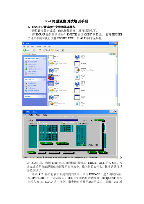
854伺服液位调试培训手册1,ENSITE调试软件安装和基本操作:液位计安装完成后,确认接线正确,就可以送电了。
将ENRAF提供的调试软件ENSITE直接COPY到D盘,打开ENSITE 文件夹中的可执行文件ENSITE.EXE,按ALT+回车全屏化。
没点击SCAN后,选择1200(CIU的通讯波特率),COM1,ALL后按OK。
搜索完成后所有的现场仪表都显示在列表中,输入新的文件名,按确认就可以开始调试了。
单击ALL将所有表添加到右侧列表中,单击ENCASE,进入调试界面,按SPLIT=OFF打开显示窗口,SELECT可以任意切换罐,REQUEST是指令输入窗口,SEND送出指令。
指令送出后显示&表示成功,显示!058或者!053表示失败。
当然,调试同样可以使用手操器PET 在罐上进行。
所有指令都完全一一样。
当调试完液位计后,单击左侧的LOG,将液位计的所有设置备份到相应文件下:D:\ENSITE\DAT\文件名\罐名2,液位计基本设置:新的液位计送电后会显示+027.0000,这是出厂的设置。
输入FR停住浮子,检查DC(磁鼓周长是否和磁鼓上刻的是否一致)。
输入:W2=ENRAF2 指令输入密码DW=+.26540000E+03 预设浮子的重量(数值刻在浮子上)(D isplacer W eight)DV=+.20040000E+03 设置浮子体积(数值刻在浮子上)(D isplacer V olume)S1=+.20800000E+03 预设测量液位(I1)时钢丝张力的平衡值(S et point1)S2=+.05000000E+03 设定浮子到罐底(I2)钢丝张力的平衡值(S et point2)TA=03 新的仪表地址(原先是00)(T ransmission A ddress)TI=TK-003 输入罐的编号,空格补齐6位(T ank I dentifier)WT=EDE 力传感器保护(W ire T ension protection)ML=+000.0000 马达低限位由1米改成0。
DMC2004VK-7;中文规格书,Datasheet资料
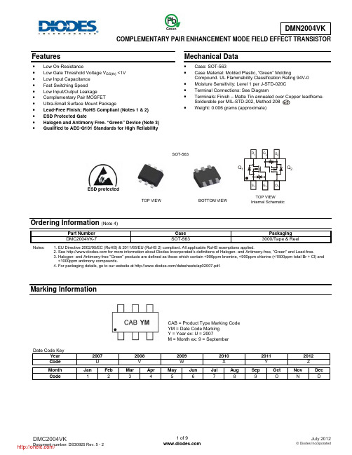
COMPLEMENTARY PAIR ENHANCEMENT MODE FIELD EFFECT TRANSISTORFeatures• Low On-Resistance • Low Gate Threshold Voltage V GS(th) <1V • Low Input Capacitance • Fast Switching Speed • Low Input/Output Leakage • Complementary Pair MOSFET • Ultra-Small Surface Mount Package • Lead-Free Finish; RoHS Compliant (Notes 1 & 2) • ESD Protected Gate • Halogen and Antimony Free. “Green” Device (Note 3) • Qualified to AEC-Q101 Standards for High ReliabilityMechanical Data• Case: SOT-563 • Case Material: Molded Plastic, “Green” MoldingCompound. UL Flammability Classification Rating 94V-0 • Moisture Sensitivity: Level 1 per J-STD-020C • Terminal Connections: See Diagram • Terminals: Finish – Matte Tin annealed over Copper leadframe.Solderable per MIL-STD-202, Method 208 • Weight: 0.006 grams (approximate)Ordering Information (Note 4)Part Number Case Packaging DMC2004VK-7SOT-563 3000/Tape & ReelNotes: 1. EU Directive 2002/95/EC (RoHS) & 2011/65/EU (RoHS 2) compliant. All applicable RoHS exemptions applied.2. See for more information about Diodes Incorporated’s definitions of Halogen- and Antimony-free, "Green" and Lead-free.3. Halogen- and Antimony-free "Green” products are defined as those which contain <900ppm bromine, <900ppm chlorine (<1500ppm total Br + Cl) and <1000ppm antimony compounds.4. For packaging details, go to our website at /datasheets/ap02007.pdf.Marking InformationDate Code KeyYear 2007 200820092010 20112012Code U V W X Y ZMonth Jan Feb Mar Apr May Jun Jul Aug Sep Oct Nov Dec Code 1 2 3 4 5 6 7 8 9 O N De3SOT-563TOP VIEWInternal SchematicTOP VIEW BOTTOM VIEWESD protectedQ 2CAB = Product Type Marking Code YM = Date Code Marking Y = Year ex: U = 2007 M = Month ex: 9 = September GreenMaximum Ratings N-CHANNEL – Q 1 (@T A = +25°C, unless otherwise specified.)Characteristic Symbol Value UnitDrain Source Voltage V DSS20 V Gate-Source Voltage V GSS±8 V Drain Current (Note 5) T A = +25°C T A = +85°CI D670480 mAMaximum Ratings P-CHANNEL – Q 2 (@T A = +25°C, unless otherwise specified.)Characteristic Symbol Value UnitDrain Source VoltageV DSS-20 V Gate-Source Voltage V GSS±8 V Drain Current (Note 5) T A = +25°C T A = +85°CI D-530-380 mAThermal CharacteristicsCharacteristic Symbol Value UnitPower Dissipation (Note 5) P D400 mW Thermal Resistance, Junction to Ambient (Note 5) R θJA 312.5 °C/W Operating and Storage Temperature RangeT j , T STG-65 to +150 °CNote:5. Device mounted on FR-4 PCB.Electrical Characteristics N-CHANNEL – Q 1 (@T A = +25°C, unless otherwise specified.)Characteristic SymbolMin Typ Max Unit Test Condition OFF CHARACTERISTICS (Note 6) Drain-Source Breakdown Voltage BV DSS 20 ⎯ ⎯V V GS = 0V, I D = 10µAZero Gate Voltage Drain Current I DSS ⎯ ⎯ 1.0 µAV DS = 16V, V GS = 0V Gate-Source LeakageI GSS ⎯ ⎯ ± 1.0µA V GS = ±4.5V, V DS = 0VON CHARACTERISTICS (Note 6) Gate Threshold VoltageV GS(th) 0.5 ⎯ 1.0 V V DS = V GS , I D = 250µAStatic Drain-Source On-Resistance R DS (ON)⎯ ⎯ ⎯ 0.4 0.5 0.7 0.550.70 0.90 Ω V GS = 4.5V, I D = 540mA V GS = 2.5V, I D = 500mA V GS = 1.8V, I D = 350mAForward Transfer Admittance |Y fs | 200 ⎯ ⎯ mS V DS =10V, I D = 0.2ADiode Forward Voltage (Note 6) V SD 0.5 ⎯ 1.2 V V GS = 0V, I S = 115mA DYNAMIC CHARACTERISTICS Input Capacitance C iss ⎯ ⎯ 150 pF V DS = 16V, V GS = 0Vf = 1.0MHz Output CapacitanceC oss ⎯ ⎯ 25 pF Reverse Transfer Capacitance C rss ⎯ ⎯ 20 pF Reverse Transfer CapacitanceC rss⎯⎯20 pFNotes: 6. Short duration pulse test used to minimize self-heating effect.Electrical Characteristics P-CHANNEL – Q 2 (@T A = +25°C, unless otherwise specified.)Characteristic SymbolMin Typ Max Unit Test Condition OFF CHARACTERISTICS (Note 6) Drain-Source Breakdown Voltage BV DSS -20 ⎯ ⎯V V GS = 0V, I D = -250µAZero Gate Voltage Drain Current I DSS ⎯ ⎯ -1.0 µAV DS = -20V, V GS = 0V Gate-Source LeakageI GSS ⎯ ⎯ ± 1.0µA V GS = ±4.5V, V DS = 0VON CHARACTERISTICS (Note 6) Gate Threshold VoltageV GS(th) -0.5 ⎯ -1.0 V V DS = V GS , I D = -250µAStatic Drain-Source On-Resistance R DS (ON)⎯ 0.7 1.1 1.7 0.91.42.0 Ω V GS = -4.5V, I D = -430mA V GS = -2.5V, I D = -300mA V GS = -1.8V, I D = -150mAForward Transfer Admittance |Y fs | 200 ⎯ ⎯ mS V DS =10V, I D = 0.2ADiode Forward Voltage (Note 6) V SD -0.5 ⎯ -1.2 V V GS = 0V, I S = -115mA DYNAMIC CHARACTERISTICS Input Capacitance C iss ⎯ ⎯ 175 pFV DS = -16V, V GS = 0Vf = 1.0MHzOutput CapacitanceC oss ⎯ ⎯ 30 pFReverse Transfer CapacitanceC rss⎯⎯20 pFNotes: 6. Short duration pulse test used to minimize self-heating effect.Q 1, N-CHANNELFig. 1 Typical Output CharacteristicsDS I , D R A I N C U R R E N T (A )Fig. 2 Typical Transfer CharacteristicsGS I , D R A I N C U R R E N T (A )D Fig. 3 Gate Threshold Voltage vs. Ambient TemperatureA V , G A T E T H R E S H O L D V O L T A G E (V )G S (t h)I , DRAIN CURRENT (A)Fig. 4 Static Drain-Source On-Resistancevs. Drain CurrentDI , DRAIN CURRENT (A)Fig. 5 Static Drain-Source On-Resistancevs. Drain CurrentD I , DRAIN-SOURCE CURRENT (A)Fig. 6 Static Drain-Source On-Resistance vs.Drain-Source Current vs. Gate Source VoltageDQ 1, N-CHANNEL (cont.)T , AMBIENT TEMPERATURE (°C)Fig. 7 Static Drain-Source On-State Resistancevs. Ambient TemperatureAFig. 9 Forward Transfer Admittance vs. Drain Current DV , DRAIN-SOURCE VOLTAGE (V)Fig. 10 Typical CapacitanceDSQ 2, P-CHANNEL-V , DRAIN SOURCE VOLTAGE (V)Fig. 11 Typical Output CharacteristicsDS -I , D R A I N C U R R E N T (A )DFig. 12 Typical Transfer CharacteristicsGS -I , D R A I N C U R R E N T (A )D Fig. 13 Gate Threshold Voltage vs. Ambient TemperatureA -V , G A T E T H R E S H O L D V O L T A G E (V )G S (t h)-I , DRAIN-SOURCE CURRENT (A)Fig. 14 Static Drain-Source On-Resistance vs. Drain CurrentD -I , DRAIN-SOURCE CURRENT (A)Fig. 15 Static Drain-Source On-Resistance vs.Drain CurrentDFig. 16 Static Drain-Source On-Resistance vs.Drain-Source Current vs. Gate Source VoltageDQ 2, P-CHANNEL (cont.)Fig. 17 Static Drain-Source On-State Resistancevs. Ambient TemperatureAFig. 19 Forward Transfer Admittance vs. Drain CurrentD -V , DRAIN-SOURCE VOLTAGE (V)Fig. 20 Typical CapacitanceDSPackage Outline DimensionsSuggested Pad LayoutSOT563Dim Min Max Typ A 0.15 0.30 0.20 B 1.10 1.25 1.20 C 1.55 1.70 1.60 D - - 0.50 G 0.90 1.10 1.00 H 1.50 1.70 1.60 K 0.55 0.60 0.60 L 0.100.30 0.20 M 0.10 0.18 0.11 All Dimensions in mmDimensions Value (in mm)Z 2.2 G 1.2 X 0.375 Y 0.5C11.7 C20.5 XZYC1C2C2GIMPORTANT NOTICEDIODES INCORPORATED MAKES NO WARRANTY OF ANY KIND, EXPRESS OR IMPLIED, WITH REGARDS TO THIS DOCUMENT, INCLUDING, BUT NOT LIMITED TO, THE IMPLIED WARRANTIES OF MERCHANTABILITY AND FITNESS FOR A PARTICULAR PURPOSE (AND THEIR EQUIVALENTS UNDER THE LAWS OF ANY JURISDICTION).Diodes Incorporated and its subsidiaries reserve the right to make modifications, enhancements, improvements, corrections or other changes without further notice to this document and any product described herein. Diodes Incorporated does not assume any liability arising out of the application or use of this document or any product described herein; neither does Diodes Incorporated convey any license under its patent or trademark rights, nor the rights of others. Any Customer or user of this document or products described herein in such applications shall assume all risks of such use and will agree to hold Diodes Incorporated and all the companies whose products are represented on Diodes Incorporated website, harmless against all damages.Diodes Incorporated does not warrant or accept any liability whatsoever in respect of any products purchased through unauthorized sales channel. Should Customers purchase or use Diodes Incorporated products for any unintended or unauthorized application, Customers shall indemnify and hold Diodes Incorporated and its representatives harmless against all claims, damages, expenses, and attorney fees arising out of, directly or indirectly, any claim of personal injury or death associated with such unintended or unauthorized application.Products described herein may be covered by one or more United States, international or foreign patents pending. Product names and markings noted herein may also be covered by one or more United States, international or foreign trademarks.LIFE SUPPORTDiodes Incorporated products are specifically not authorized for use as critical components in life support devices or systems without the express written approval of the Chief Executive Officer of Diodes Incorporated. As used herein:A. Life support devices or systems are devices or systems which:1. are intended to implant into the body, or2. support or sustain life and whose failure to perform when properly used in accordance with instructions for use provided in thelabeling can be reasonably expected to result in significant injury to the user.B. A critical component is any component in a life support device or system whose failure to perform can be reasonably expected to cause thefailure of the life support device or to affect its safety or effectiveness.Customers represent that they have all necessary expertise in the safety and regulatory ramifications of their life support devices or systems, and acknowledge and agree that they are solely responsible for all legal, regulatory and safety-related requirements concerning their products and any use of Diodes Incorporated products in such safety-critical, life support devices or systems, notwithstanding any devices- or systems-related information or support that may be provided by Diodes Incorporated. Further, Customers must fully indemnify Diodes Incorporated and its representatives against any damages arising out of the use of Diodes Incorporated products in such safety-critical, life support devices or systems.Copyright © 2012, Diodes Incorporated分销商库存信息: DIODESDMC2004VK-7。
_NCCP1H010_MoveAbsolute_REAL
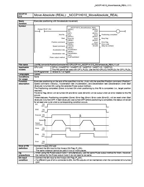
NCCP1HMove Absolute (REAL): _NCCP1H010_MoveAbsolute_REAL 010■ Variable TableOutput Variables Name Variable name Data type Range DescriptionENO ENO BOOL 1(ON): FB operating normally0(OFF): FB not operating normallyPositioning completed Done BOOL 1 (ON) indicates that positioning is completed.Busy flag Busy BOOL 1 (ON) indicates that the FB is in pregress.Error flag Error BOOL 1 (ON) indicates that an error has occurred in the FB. Error code(May be omitted)ErrorIDWORDThe error code of the error occurred in the FB will be output. For details of the errors, refer to the sections of the manual listed in the Related manuals above. When Unit No. or Axis. No. is out of the range, #0000 will be output.Limitation of Function block by Combination of CPU type and Unit Version CPU Type Unit Version Axis No. Range of Frequency Description 1.1 &0 to &3 +1.0 to +100000.0 &0 to &1 +1.0 to +100000.0XA / X 1.0 &2 to &3 +1.0 to +30000.0Please use Function Block Version1.10 or higher whenyou set values that are larger than 30000.0Hz to Axis. No.2 or No.3. &0 to &1 +1.0 to +1000000.0 Y 1.1 &2 to &3 +1.0 to +100000.0Please use Function Block Version1.10 or higher forCP1H-Y20DT-D.■ Revision History Version Date Contents 1.10 2006.5. Addition of CP1H CPU Unit unit version 1.1 1.00 2005.9. Original productionNoteThis document explains the function of the function block.It does not provide information of restrictions on the use of Units and Components or combination of them. For actual applications, make sure to read the operation manuals of the applicable products.。
EM70系列指令手册勘误表说明书

On each of the following screens, a value within a setting range or an item from those displayed is selected and set.Event SettingEvent 1 type setting screen Initial value:Select from the following types shown on the screen.: No setting (initial value): Lower limit side degree of opening : Higher limit side degree of opening : Lower limit side input : Higher limit side input : Automatic : Manual: degree of opening error : Input error: Control loop errorNote: However, a set value is initialized when the type of event is changed.Event 1 hysteresis setting screen Initial value: 0.1%Setting range: 0.1~5.0%Select a value within the setting range. S etting is possible only when the event is higher and lower limit alarm. ( , , , )Event 1 stand-by action setting screen Initial value:Select either of the following: : With stand-by action : Without stand-by actionS etting is possible only when the event is higher and lower than the limit alarm. ( , , , )Event 2 type setting screen Initial value:T he same as event 1.Event 2 hysteresis setting screen Initial value: 0.1%Setting range: 0.1~5.0%T he same as event 1.Event 2 stand-by action setting screen Initial value:Select either of the following: : With stand-by action : Without stand-by action T he same as event 1Screen Group 11-0 automatic adjustment screen or 1-00 manual adjustmentEvent 3 type setting screen Initial value:T he same as event 1.Event 3 hysteresis setting screen Initial value: 0.1%Setting range: 0.1~5.0%T he same as event 1.Event 3 stand-by action setting screen Initial value:Select either of the following shown on the screen:: With stand-by action : Without stand-by action T he same as event 1Setting of Motor Action at the Time of Position ErrorScreen for setting motor action at the Time of position error Initial value:Select from the following shown on the screen: : Motor stop : Motor close : Motor openP osition error: When the value of position is less than the set range of position errors (Po_LL) and when the value of position is more than the set range of position errors (Po_HH).D uring manual operation, action setting upon occurrence of a position error is not valid since manual operation is given the first priority.I n case of SSR position error output, the motor speed is put in action.Screen for Setting Motor Action Time at the time of Position ErrorScreen for setting motor action time at the time of position error Initial value: 300 seconds Setting range: 1~300 seconds Set a time within the setting range.S etting is possible only when "open" or "close" has been set against position degree. C ontrol output will output for each setting time.Setting of Motor Action at the Time of Input ErrorScreen for setting motor action at the time off input error Initial value:Select from the following shown on the screen: : Action in response to abnormal input signal: Motor stop: Motor to be adjusted to set degree of openingI nput error: An input error means that input data is below -10% (In-LL displayed) or above 110% (In-HH).D uring manual operation, suspension of operation and control with present value of position, input error is not dealt with.Screen for setting degree of opening against input errorInitial value: 0%Setting range: 0~100%Set a value within the setting range.S etting is possible only when a value of position is selected as the setting for input error.The set value of position is limited by higher/lower limit position limiters.Analog output setting screenInitial value:Select from the following shown on the screen: : Input is output.: Position is output.Note: When analog output is changed on this screen, higher and lower limit values of analog output are initialized.Lower limit side analog output setting screenInitial value: 0%Setting range: 0~100%Inversed scale is possible(lower limit value ≠ higher limit value, though).Higher limit side analog output setting screenInitial value: 100%Setting range: 0~100%Inversed scale is possible(lower limit value ≠ higher limit value, though).For the communication mode, please refer to the communication instruction manual provided separately.Communication setting screenInitial value:Select from the following:: Communication local mode (initial value): Communication modeK ey operation can make a change only from the communication mode to the communica-tion local mode.I n communication mode, keylock is effective on all the setting screens except manual operation.Communication address setting screen Initial value: 1Setting range: 1~99I n case a plurality of controllers are linked for communication, addresses need to be set individually.Communication rate setting screenInitial value:Set a value from the following shown on the screen:: 1200 bps (initial value): 2400 bps: 4800 bps: 9600 bps: 19200 bpsT he speed of communication should be setPto interrupt communication and to change to the local mode. To restart communication, the speed should be set correspondingly to that of the host computer.Communication data format setting screen Initial value:Select from the following:: 7E1: 7E2: 7N1: 7N2: 8E1: 8E2: 8N1: 8N2T he length of data bits, parity and the length of stop bits are set.Communication control code setting screen Initial value: 1Setting range: 1, 2 and 3Select from the following shown on the screen: : STX_ETX_CR: STX_ETX_CRLF: @_:_CRA communication control code is set. Communication BCC check setting screen Initial value: 1Setting range: 1, 2, 3 and 4Select from the following shown on the screen: : ADD: ADD_two' s cmp: XOR: NoneA BCC processing method to be used in BCC checking is selected. Communication memory mode setting screenInitial value:Select from the following shown on the screen: : EEPROM (initial value)Data is written in memory.: RAMData is written in RAM.Communication delay time setting screen Initial value: 20Setting range: 0~100①A delay time from receiving a communication command to carrying out transmission is set.②Delay time = Set value of communication delay time × 0.25 msec.Input range setting screen Initial value:in the case of current input in the case of voltage inputSelect one from the following types of current input.: 4~20mA (initial value): 0~20mASelect one from the following types of voltage input.: 0~10V (initial value): 0~5V : 1~5VInput filter setting screen Initial value: 0 secondSetting range: 0~99 seconds①A time constant of primary delay filter is set.②The influence of noise contained in control input signal is mitigated and control is stabilized.Screen for setting input scaling/degree of opening scaling Initial value:Select from the following shown on the screen: : Input scaling (initial value) : Scaling of degree of opening①When the setting of input scaling or scaling of the degree of opening is changed, lower and higher limit values of the scaling are initialized.②Input scaling: Higher and lower limit values of input are set respectively against 0% and 100% positions.③Position scaling: Higher and lower limit positions are set respectively against 0% and 100% inputs.Scaling lower limit setting screen Initial value: 0%Setting range: −10~109%(lower limit < higher limit)i s o P i s o P Input0InputScaling higher limit setting screen Initial value: 100%Setting range: −9~110%(lower limit < higher limit)Screen for setting lower limit value of position limiter Initial value: 0%Setting range: 0~99%(lower limit < higher limit)Screen for setting higher limit Motor speed adjustment “1G” setting screen Initial value: 100%Setting range: 10―100%When voltage / current input (automatic oper-ation) is selected , motor speed adjustment is carried out with the parameter “1G”.side value of position limiter Initial value: 100%Setting range: 1~100% (lower limit < higher limit)Position limiter is effective except during manual operation and position abnormality.Preset values of position through externaloperating input and preset values of position at the time of input error also become effective.Motor speed adjustment setting screen Initial value: 100%Setting range: 10~100%①The motor speed is adjustable when SSR output is selected.②When the motor speed is adjusted, control is carried out with a set cycle time (initial value: 500 msec.) as one cycle.¥ In the case of 10% selected on the motor speed adjustment screen:¥ Motor action time set at 50%Inputthe 1-0 automatic adjustment screen or 1-00 manual adjustment screen.ToOutput characteristics setting screen Initial value:Select from the following shown on the screen: : Direct characteristics (initial value) : Reverse characteristics①Direct characteristics (DA): Control is carried out in the state that the direction in which input increases and decreases is the same as the direction in which the value of position increases and decreases.②Reverse characteristics (RA): Control is carried out in the state that the direction in which input increases and decreases is opposite to the direction in which the value of position increases and decreases.Note: In case is selected for external input, setting is not possible and the screen is for monitoring only.Dead band setting screen Initial value: 2.0%Setting range: 0.2~10.0%①In case the control motor has higher inertia, hunting (opening and closing are repeated without stopping) may be caused. To prevent this, set a larger value for dead band.When control of high precision is needed, a smaller value should be set for dead band.You must be very careful since smaller dead band tends to result in hunting.②Hysteresis: One fourth of dead band.The minimum value of hysteresis is 0.2%.of positionHysteresis setting screen Initial value: PrPSetting range: PrP, 0.0―5.0%When set to “PrP”, hysteresis is fixed to 1/4 of dead band.If dead band is less than 0.8%, hysteresis is fixed to 0.2%.Keylock setting screen Initial value: 0Setting range: 0, 1, 2 and 3Select from the following shown on the screen: : Without keylock (initial value) : Keylock of screen groups 1 and 2 : All keylock except manual operation: All keylock (In case manual operation is set7-5.Explanation of Screen Group 2 (Special Screen Group)and SettingData in this screen group should be set only by one with thorough knowledge of the EM70 series and the system. Generally, the instrument is usable without changing the initial values in this screen group.In the screen group 2 (special screen group), setting and reading screen group).screen.The screen group 2 comprises 4 special screens, of which the sequence is shown in the following. Screen for setting square root extraction function Initial value:Select from the following shown on the screen: : With square root extraction : Without square root extraction Control is carried out by calculatingopening/closing degrees, using the square of input as a target position value.Motor speed adjustment “2G” setting screen Initial value: oFSetting range: oF, 10―100%When DI preset Value operation is selected, motor speed adjustment is carried out with the parameter “2G”.If set to “oF ”, motor speed adjustment is carried out with the parameter “1G”.next page。
云系列DAM0404D-WIFI+网口版产品说明书

云系列DAM0404D-WIFI+网口版产品说明书云系列DAM0404D-WIFI+网口版说明书V1.0北京聚英翱翔电子有限责任公司2016年01月目录一、产品说明 (1)二、产品特点 (1)三、产品功能 (1)四、产品选型 (1)五、主要参数 (1)六、通讯架构说明 (2)七、快速使用说明 (2)八、硬件说明 (3)1、接口说明 (3)2、尺寸说明 (3)3、引脚说明 (5)4、继电器接线说明 (6)5、有源开关量接线示意图 (6)6、无源开关量接线示意图 (7)九、设备参数配置及测试..............................................................................错误!未定义书签。
十、设备唯一ID号........................................................................................错误!未定义书签。
1、扫描二维码获取................................................................................错误!未定义书签。
2、使用软件获取【选用】....................................................................错误!未定义书签。
十一、平台软件说明......................................................................................错误!未定义书签。
十二、开发资料说明. (7)1.工作模式说明 (10)2、Modbus寄存器说明 (10)2.相关指令 (12)3.指令详解 (12)十三、技术支持联系方式 (14)一、产品说明DAM0404设备是我公司云系列设备中网络版的一种,设备通过连接Internet广域网来进行通讯,使用我司配套的云平台软件可实现远程控制设备功能,每个设备具有唯一ID号方便用户进行二次开发使用。
Unicore UM4B0 Installation and Operation User Manu

U ni c o r e C o n f i dINSTALLATION AND OPERATIONUSER MANUALData subject to change without notice.Communications, Inc.Copyright© 2009-2021, Unicore RTK Positioning ModuleAll-constellation All-frequency GPS/BDS/GLONASS/Galileo U M 4B0DisclaimerInformation in this document is subject to change without notice and does not represent a commitment on the part of Unicore Communications, Inc. No part of this manual may be reproduced or transmitted in any form or by any means, electronic or mechanical, including photocopying and recording, for any purpose without the express written permission of a duly authorized representative of Unicore Communications, Inc. The information contained within this manual is believed to be true and correct at the time of publication.© Copyright 2009-2021 Unicore Communications, Inc. All rights RSV.UM4B0 User Manual ForewordThis <User Manual> offers you information in the features of the hardware, the installation, specification and use of UNICORECOMM UM4B0 product.This manual is a generic version. Please refer to the appropriate part of the manual according to your purchased product configuration, concerning CORS, RTK and Heading.Readers it applies toThis <User Manual> is applied to the technicists who know GNSS Receiver to some extent but not to the general readers.Contents1INTRODUCTION (1)1.1O VERVIEW (1)1.2K EY F EATURES (1)1.3T ECHNICAL S PECIFICATIONS (2)1.4I NTERFACES (2)2HARDWARE (3)2.1D IMENSIONS (3)2.2P IN D EFINITION (T OP V IEW) (4)2.3E LECTRICAL S PECIFICATIONS (6)2.4O PERATIONAL C ONDITIONS (7)2.5P HYSICAL S PECIFICATIONS (7)3HARDWARE DESIGN (8)3.1D ESIGN IN C ONSIDERATIONS (8)3.2UM4B0R EFERENCE D ESIGN (9)3.3P INS (10)3.4PCB P ACKAGING (11)3.5R ESET S IGNAL (12)3.6A NTENNA (12)3.7E XTERNAL A NTENNA F EED D ESIGN (12)4INSTALLATION AND CONFIGURATION (14)4.1ESD H ANDLING P RECAUTIONS (14)4.2H ARDWARE I NSTALLATION (14)4.3S TART U P (17)4.4C ONFIGURATION AND O UTPUT (17)4.4.1Operation Procedures (18)5CONFIGURATION COMMANDS (19)5.1RTK R EFERENCE S TATION C ONFIGURATION (20)5.2RTK R OVER C ONFIGURATION (21)5.3M OVING B ASE C ONFIGURATIONS (21)5.4H EADING C ONFIGURATION (21)6ANTENNA DETECTION (22)7FIRMWARE UPGRADE (22)8PRODUCTION REQUIREMENT (24)9PACKAGING (25)1Introduction1.1OverviewUM4B0 is a high precision positioning and heading RTK module developed by Unicore Communications, targeting light robots, UAVs, intelligent vehicles, GIS information collection, etc.By employing a single UC4C0 (432 channel tracking) baseband chip and a single RF chip, using single-sided SMD packaging, UM4B0 has achieved the smallest size(30x40mm) in this industry with high accuracy heading and positioning output. It can simultaneously track BDS B1I/B2I/B3I/B1C/B2a + GPS L1/L2/L5 + GLONASSL1/L2+Galileo E1/E5a/E5b.Figure 1-1 UM4B0 Module1.2Key Features•30*40mm, the smallest multi-system multi-frequency high precision module •Support GPS L1/L2/L5+GLONASS L1/L2+BDS B1I/B2I/B3I/B1C/B2a+Galileo E1/E5a/E5b•Based on 432 channel NebulasII GNSS SoC•20Hz update rate•Instant RTK initialization and long-distance RTK•Enhanced multi-system multi-frequency RTK technology, JamShield adaptive narrow-band anti-interference and U-AutoAlign multi-path mitigation •Support odometer input and external high-performance IMU interface* •SMD packagingUM4B0 User Manual 1.3Technical SpecificationsTable 1-1 Performance SpecificationsTable 1-2 Functional Ports1.4InterfacesFigure 1-2 Block Diagram1.RF PartThe receiver gets filtered and enhanced GNSS signal from the antenna via a coaxial cable. The RF part converts the RF input signals into the IF signal, and converts IF analog signal into digital signals required for NebulasII (UC4C0) digital processing.2.NebulasII SoC (UC4C0)The UM4B0 incorporates the processing from the NebulasII (UC4C0), UNICORECOMM’s new generation high precision GNSS SoC with 55nm low power design, which supports up to 12 digital intermediate frequency or 8 analog intermediate frequency signals and can track 12 navigation signals with 432 channels.3.1PPSUM4B0 outputs 1 PPS with adjustable pulse width and polarity.4.EventUM4B0 provides 1 Event Mark Input with adjustable pulse width and polarity.2Hardware2.1DimensionsUM4B0 User ManualFigure 2-1 Mechanical Dimensions2.2Pin Definition (Top View)Figure 2-2 UM4B0 Pin DiagramTable 2-2 Pin DefinitionUM4B0 User Manual2.3Electrical SpecificationsTable 2-3 Absolute Maximum Ratings2.4Operational ConditionsTable 2-4 Operational ConditionsNOTE: Since the product contains capacitors at the input, inrush current will occur during power-on. Evaluate in the actual environment in order to check the effect of the supply voltage drop due to the inrush current.2.5Physical SpecificationsTable 2-5 Physical Specifications3Hardware Design3.1Design in ConsiderationsTo make UM4B0 work properly, you need to properly connect the following:The module VCC power-on behavior is repeatable, the initial level is lower than0.4V, and the undershoot and ringing should be guaranteed to be within 5% VCC Provide stable power to the VCC pinConnect all the GND pins to groundConnect VBAT pin to a 3.0V power supplyConnect ANT_IN signal to the antenna, and ensure the 50-ohm impedance matchingConnect ANT_PWR to +3.3~5.5 V voltage, then supply +3.3~5.5 V feed to the antenna through ANT_INEnsure COM1 is connected to a PC or an external processor, and users can use this serial port to receive position data. COM1 is also necessary for firmwareupgradesProperly connect the module’s reset pin FRESET_N to ensure complete reset of the module. It will restore the module to the manufacturing configuration.When ANT_NLOD, ANT_FFLG and antenna detection indication signal are connected, the IO without any pull-up/down of the client MCU terminal isrequired at the input.In order to obtain proper performance, special concerns should be paid during the design:Power supply: A table and low ripple power supply is necessary for good performance. Make sure the peak-to-peak voltage ripple does not exceed50mVpp. It is recommended to use a power chip with current output capacity greater than 2A to power the board.-Use LDO to ensure the purity of power supply-Try to place LDO close to the module in layout-Widen the tracks of power circuit or use copper pour surface to transmit current-Avoid walking through any high-power or high inductance devices such as a magnetic coilInterfaces: Ensure that the signals and baud rate of the main equipment match those of the UM4B0 moduleAntenna interface: Make sure the antenna impedance matches, and the cable is short without any kinks, try to avoid all acute anglesTry to avoid designing in any circuits underneath UM4B0This module is a temperature sensitive device, so dramatic changes in temperature will result in reduced performance. Keep it away as far as possible from any high-power high-temperature air and heating devices3.2UM4B0 Reference DesignFigure 3-1 Minimum Reference DesignFigure 3-2 UM4B0 Reference Design 3.3PinsTable 3-1 Pin Notes3.4 PCB PackagingFigure 3-3 UM4B0 recommended PCB Packaging (unit: mil, in brackets: mm)3.5Reset SignalUM4B0 module can’t work properly unless it is correctly reset after power on. To ensure effective reset, the reset pin (RST) and power supply pin (VCC) must meet the following time sequence requirement. To reset UM4B0 during normal operation, please pull RST pin to low level for more than 5ms.Figure 3-4 UM4B0 RST3.6AntennaThe module has the antenna input pin ANT_IN, which provides a +3.3V antenna feed. When an active antenna of +3.3~5V is adopted, please make sure the 50 Ω antenna impedance is matched.Figure 3-5 UM4B0 Active Antenna Connection3.7External Antenna Feed DesignUM4B0 feeds the antenna signals to the required circuits internally, but in order to effectively prevent damage from lightning and surges, circuit protection should be installed externally to protect the module.High voltage and high-power protection chips should be used to feed the antenna from the outside of the module. A gas discharge tube, varistor, TVS tube and other high-power protective devices may also be used in the antenna circuit to effectively improve the prevention against lightning stroke and surge.ANTFigure 3-6 UM4B0 External Antenna Feed Reference CircuitRemarks:a)L1, feed inductor, 68nH RF inductor in 0603 package is recommended;b)C1, decoupling capacitor, it is recommended to connect two capacitors of 100nF/100pFin parallel;c)C2, DC blocking capacitor, recommended 100pF capacitor.4Installation and Configuration4.1ESD Handling PrecautionsUM4B0 Module is an Electrostatic Sensitive Device (ESD) and special precautions when handling are required.Electrostatic discharge may cause damages to the device. All operations mentioned in this chapter should be carried out on an antistatic workbench, wearing an antistatic wrist strap and using a conductive foam pad. If anantistatic workbench is not available, wear an antistatic wrist strap and connect the other end to a metal frame to avoid the effects of static electricity.Hold the edge of the module, not in direct contact with the componentsPlease check carefully whether the module has obviously loose or damaged components.Figure 4-1 Typical Installation of UM4B0Please check the contents of the package carefully after receiving the package of UM4B0.UM4B0 EVK suite (or evaluation board)User manualUPrecise softwareQualified antennaMMCX antenna cablePC or Laptop with serial ports (Win7 or above), with UPrecise installed4.2Hardware InstallationAfter the above preparation, please follow the steps below to install:Step 1: Make sure to take all the anti-static measures, such as wearing an anti-static wrist strap, grounding the workbench;Step 2: Align UM4B0 transfer board positioning holes and pins with EVK, and fix it in the EVK. EVK provides power supply and standard communication interface for the module to communicate with peripheral devices;NOTE: The RF connector of the board is MMCX, and the suitable connecting wire should be selected according to the package. The input signal gain at the antenna interface is optimal between 20 and 36 dB. Please select the appropriate antenna, antenna cable and online LNA accordingly.Figure 4-2 Installation InstructionStep 3: Select the GNSS antenna with appropriate gain, and fix it in a stable, non-block area, using the coaxial radio frequency cable to connect the antenna to UM4B0 EVK;Step 4: Connect the PC to the EVK serial port through direct serial cable;Figure 4-3 Connect the Serial PortStep 5: Connect a 12V adapter to the EVK power input, and switch on to powerthe device;Figure 4-4 Connect the AntennaStep 6: Open the UPrecise software on the PC;Step 7: Control the receiver through UPrecise to send commands or to log data.4.3Start UpThe power supply for UM4B0 is 3.3VDC. Before powering on the device, please connect UM4B0 serial port to the GNSS antenna. The receiver is started and the communication is connected after powering up. Testing tools are provided for module testing.4.4Configuration and OutputUNICORECOMM UPrecise software provides a user-friendly graphical interface to control and display the operation of your receiver. The features of Uprecise include: Logging Control View: Graphic interface for data loggingConsole window for sending command to the receiver (Console View)Displaying the receiver’s output in ASCII-format (ASCII View)Graphic window for displaying Position of satellite, PRN, and Signal/Noise Ratio (Constellation View)Historical and present Trajectory of the receiver (Trajectory View)Position/Velocity/Time of the receiver (PVT View)Apart from the basic functions above, UPrecise offers advanced functions as follows: Selecting and recording the logSending commands to the receiverOperating and configuration of the ASCII viewThe trajectory view for displaying the present point and the past point of the receiverSwitching Views over the tracking windowSwitching between Constellation ViewsResetting the receiverReplaying the GGA logFigure 4-5 UPrecise SoftwareUM4B0 User Manual 4.4.1Operation ProceduresStep 1. Follow 4.2 Installation Guide to connect the power source, antenna to the board, and turn on the EVK switchStep 2. Click file - > connect the serial port, and set the baud rate; the default baud rate of UB4B0M is 115200bpsFigure 4-6 Connect the Serial PortStep 3. Click the receiver settings button to configure the NMEA message output. Itis recommended to configure GPGGA, GPGSV, and other messages.Figure 4-7 NMEA Data OutputStep 4. Click the receiver settings button to configure the NMEA message output, then click send. It is recommended to configure GPGGA, GPGSV, and other messages. Step 5.In the data session window, click “Send all Message” to complete all the NMEA message output (update rate 1Hz). Right click in the data session window to adjust: output log font size, stop / resume log output, or clear log content, etc.Step 6. Use various views of UPrecise to configure or input commands as required.5Configuration CommandsUM4B0 supports abbreviated ASCII format. Simplified ASCII format without check bit is more accessible to user commands. All commands are composed of a log heading and configuration parameters (If parameters are null, there will be only one heading in the command). Header field contains the command name or message headers. UM4B0 is simple to use, and common instructions are shown in the following table:UM4B0 User Manual5.1RTK Reference Station ConfigurationIf the precise coordinates are known, the precise coordinates could be set as in this example:Mode base 40.07898324818 116.23660197714 60.4265 // set lat lon heightrtcm1033 com2 10 // RTCM1033 input from com2rtcm1006 com2 10rtcm1074 com2 1rtcm1084 com2 1rtcm1094 com2 1rtcm1124 com2 1saveconfigIf precise coordinates are unknown:Mode base time 60 1.5 2.0 // 60 seconds position averagertcm1033 com2 10rtcm1006 com2 10rtcm1074 com2 1rtcm1084 com2 1rtcm1094 com2 1rtcm1124 com2 1saveconfig5.2RTK Rover ConfigurationRTK Rover stations (rover station) receive differential correction data sent from reference stations and receive satellite signals to provide an RTK positioning solution and realize RTK high-precision positioning with cm or mm-level accuracy. Common instructions for configuring RTK rover are as follows:gngga 1saveconfig5.3Moving Base ConfigurationsRTK reference station provides precisely known coordinates of a fixed station. Unlike the RTK reference station, moving base station is in motion, at the same time receives the satellite information, and sends it to the rover station receiver (to be determined) directly or after processing. The rover station receiver receives satellite observations as well as information from the moving base station, to make relative positioning and determine the position of the rover station. Commonly used instructions to set the moving base station are as follows:Mode movingbasertcm1006 com2 1rtcm1074 com2 1rtcm1084 com2 1rtcm1094 com2 1rtcm1124 com2 1saveconfig5.4Heading ConfigurationGNSS heading refers to the clockwise angle between true North and the baseline vector constituted by the two GNSS antennas. Commonly used instructions are as follows:Mode headinggphdt com1 1saveconfigUM4B0 User Manual6Antenna Detection1The UM4B0 module offers antenna open/short detection. The corresponding pins are ANT_NLOAD and ANT_FFLG.•The current monitoring chip outputs 2 bit high and low voltage; the software portion sets 2 bit IO of corresponding NII as input pull-up, and then queries the status of 2 bit IO to check the antenna state.•If ANT_PWR malfunctions, the query result is invalid.•If the antenna is not fed by ANT_PWR but by other means, the query result is invalid.7Firmware UpgradeUprecise software is used for the remote update of UM4B0. Please follow the steps below to upgrade the device:Figure 7-1 Update InterfaceClick “…” to browse the firmware update package, and click“Start” to start the firmware upgrading process (uncheck software reset):1 Optional by FirmwareFigure 7-2 Update StepsWaiting for the process to complete 100% (the upgrade time is normally within 5min):Figure 7-3 Update StepsPlease use COM1 only to update firmware.UM4B0 User Manual8Production RequirementRecommended thermal cycle curve is as follows:Figure 8-1 Soldering TemperatureTemperature rising stage∙Rising slope: Max. 3℃/s∙Rising temperature range:50℃-150℃Preheating stage∙Preheating time: 60 – 120 s∙Preheating temperature range: 150 - 180℃Reflux Stage∙Over melting temperature (217℃) time: 40 – 60 s∙Peak temperature: no higher than 245℃Cooling Stage∙Cooling slope: Max. 4℃ / sNotes:In order to prevent fall off during soldering of the modules, please avoid soldering the module in the back of the Board during design, that is, better not to go through soldering cycle twice.The setting of temperature depends on many factors, such as type of Board, solder paste type, solder paste thickness, etc. Please also refer to the relevant IPC standards and indicators for solder paste.Since the lead soldering temperatures are relatively low, if using this soldering method, please give priority to other components on the Board.9PackagingUM4B0 modules are delivered in trays, which is suitable for mainstream SMT equipment. Each box contains 5 trays, so there are 150 UM4B0 modules in the box. Table 9-1 Package Informationw 。
蒂森控制板操作器说明书

DIAGNOSTIC UNIT IFunction 01 00 Display of error stack as per:05.00显示故障堆栈 Example:ErrorExplanationWeighting BWlanding 楼层S stopping 停止undefined 未定义M spontaneous message 自发信息 explanations from page 21 解释21页B lift blocked 电梯被锁定 Number of marking flag 标志编Significance: Frequency levels of error:含义:故障频繁度Level 1 infrequent 1度不频繁11) Dependenton the function involved, reset can either mean emergency stop following by adjusting run or stopping of the lift installation2) Handshake is defined as cyclical data exchange (telegram) between two data carriers.1) SR module can be masked out via teach-in mode function AF 0d. Running-open operation and re-1) Error from TCI work program 03.89/7 – no longer used.2) Error 35 00 and 3b 00 can no longer occur from work program 02.87/4 and error 36 00 can no longer occur from 06.95/25.1) SR module can be masked out through teach-in-mode function AF 0d. N Runnin-open operation and21) If errors 65 00 to 74 00 occur more than 3 times, error 4F 00 will follow afterwards, which leads to1) DSP is the digital signal processor in the CPI controller2) Handshake is defined as cyclical data exchange (telegram) between two data carriers.Explanations of the existing error code numbers04 NN TCI control – Interrogation of ZSE solenoid switchesNN is represented as a hexadecimal number; in the event of errors, it indicates the number of ZSE switches (no other than the ZSE switch of the car position may be actuated).04 00 applies to ZSE 25 t o ZSE 3104 00 applies to ZSE 17 t o ZSE 2404 00 applies to ZSE 9 to ZSE 1604 0C applies to ZSE 1 to ZSE 8Example: 0 4 0 CHexadecimal number 0C∣∣Binary number 0 0 0 0 1 1 0 0∣∣∣∣∣∣∣∣assigned ZSE switch 8 7 6 5 4 3 2 1The example shows that ZSE switches ZSE3 and ZSE4 (in 3. and 4. landing) havebeen activated. (Also compare hexadecimal code in part 4, page 2)04 NN TCM control – Interrogation of ZSE solenoid switchesIf ZSE switches are closed in the third and fourth landing, the TCM controlwill file two errors: 04 03 und 04 0406 XX TCI control–Door locking not possible (from work program version 08.91/9)The lift will be put out of service for 15 min. after 3 unsuccessful doorlocking attempts. A new locking attempt will be initiated after expiry ofthis period of time.XX = StandortDoor variant – hinged door:A new locking attempt will also be made within these 15 min. after opening of the landing door (TK open) and closingit again (TK closed).Door variant D4 (with mechanical locking device)A start attempt will be enabled within 15 min., as soon as the control receives the bolt contact.06 XX TCM control – Door locking not possibleIf open bolt contact is recognized in the command chain preceding the position the following error will follow 14 XX (XX = bolt contact main side) 18 XX (XX = bolt contact rear side)09 NN Car will be blocked in the landing >4 minExample LED Signal name (LED display on diagnostic unit Irow A) 0 KKD 0 LSD 1 KK O.K. 1 LS O.K.0 TSUD 0 TSOD 0 TSU1 TSO activatedFor LEDs and signal names see Operating Instructions of Diagnostic Unit I, function 05 00, column 0d (display of predefined memory locations, from page 25).19 NN Door zone not detected0 TO0 TU1 FL0 FS0 FO0 FUIn the operation phase STOP (lift at standstill), the CPU recognizes that thedoor zone calculated from the landing vanes was left.For LEDs and signal names see Operating Instructions Diagnostic Unit Ifunction 05 00, column 05 (display of predefined memory locations,from page25)1d NN Emergeny stop (wrong run direction)No run direction or both run directions were produced with the run contactoractivated and the brake disengaged.For LEDs and signal names see Operating Instructions, Diagnostic Unit I,function 05 00, column 05 (display of predefined memory locations from page25).In case of error 1d C8 the processor outputs the signals VR, A5A and FL (butwithout run directions); compare above representation of error 19 NN1E NN Deceleration not effectiveBinary display of car positionIt will be examined whether deceleration has been initiated already onreaching the marked terminal landing vanes.The position is indicated by the five bitst 20 to 25 as binary number.0 211 201 E 9d: bits 20 to 27 stand for landing 29, therefore only run direction UPexists, since 26 = 0 and 27 = 1, and consequently 9 d will follow.Function 02 00 Display of order number (fromTCI work program version 06.88/6 and with TCM)显示定单号码(从TCI 06.88/6版工作程序起以及TCM梯)Example: Order No.: 27 70 06 42 10∣∣∣∣∣LED 5 12 3 10 1B A B A BFunction 03 00 Position indicator (decimal)楼层显示(十进制)Function 04 00 Operation phaseFunction 05 00 Display of specified memory locations1) Set function 05 00 with program selector wheel2) Press start-stop button3)Select desired column in 7-segment display with program selector wheelExample: Column 0d is desired. For example, select 0C 0d in 7-segment display, then left LED row B applies to column 0C and right LED row A applies to column0d, etc.4) Interrogate LED display (compare overview and signal description)5) Exit: press start-stop button for longer than 2 s.The LEDs listed in the table will light on selecting the respective column (Col) :Extension of columns for TCM control with MC1 or MC2 circuit boards1) Error marking1) pulses are counted dependent on the run direction (2071) will be displayed as hexadecimal number in LED row A. Example: 09 in LED row A LEDs2) displays last failure before current failure cause column 2C. Is displayed in hexadecimal1) MF3 (VA) stands for circuit board MF3 with double-sided insertion 1) MF3 (VA) stands for circuit board MF3 with double-sided insertion1。
欧姆龙错误代码

错误代码型号品牌错误类型错误原因解决办法Uv 3G3MV 欧姆龙UV( 主回路低电压) 变频器停止时,主回路直流电压低于低电压检测值200V 级:主回路直流电压约为200V 以下时停止( 单相约为160V 以下)400V 级:主回直流电压约为400 以下时停止1.检查电源电压2.检查主回路电源线是否断线3.检查端子螺丝紧固状态ov 3G3MV 欧姆龙OV(主回路过电压)变频器停止时,主回路直流电压超过过电压检测值检测值:约410V 以上(400V级约为820V)检查电源电压oH 3G3MV 欧姆龙OH( 冷却散热座过热,变频器停止,进风温度上升检查进风温度CAL 3G3MV 欧姆龙CAL(MEMOBUS通信待机时) 参数n003( 运行指令选择)=2或参数n004(频率指令选择)=6时,且电源投入后,PLC 的正常数据没有接收到检查通信装置,传送信号oP 3G3MV 欧姆龙OPE□(MEMOBUS通信参数设定时,参数设定复(参数n050~异常)OP1:多功能输入选择的设定值重056)OP2:V/f 参数设定的大小关系有矛盾( 参数n011,013,014,016)OP3:电机额定电流的设定值超过变频器额定的150(%)( 参数n036)OP4:频率指令上限和下限大小相反( 参数n033,034)OP5:跳跃频率1,2,3 的大小关系有矛盾( 参数n083,084,085)OP9:负载频率设定不正确( 参数n080)检查设定值oL3 3G3MV 欧姆龙变频器输出电流超过过力矩检测值( 参数n098:过力矩检测值)降低负载,延长加减速时间SEr 3G3MV 欧姆龙SER( 顺序异常) 变频器运行中接到了面板/远距通信控制回路端子切换信号检查外部回路( 顺控器)bb 3G3MV 欧姆龙BB( 外部基极锁定) 外部基极锁定收到后,变频器输出切断( 注:外部基本延时解除后运行重新开始)检查外部回路( 顺控器)STP 3G3MV 欧姆龙1.STP( 操作器停止) 控制回路端子的正转、反转指令运行中按操作器的STOP/RESET键,此时变频器将按停止方法设定(n005)停止2.STP( 紧急停止) 接到紧急停止报警信号,变频器将按停止方法设定(n005) 停止1.将控制回路端子的正转反转指令设为“开”2.检查外部回路( 顺控器)FAn 3G3MV 欧姆龙FAN( 冷却风扇异常)冷却风扇被卡住了1.检查冷却风扇2.检查冷却风扇的接线CE 3G3MV 欧姆1.CE(MEMOBUS) 通信异常2.通信数据不能正常受信检查通信设备,通信信号龙EF 3G3MV 欧姆龙1.EF( 正转·反转指令同时投入)控制回路端子的正转指令和反转指令同时为“闭”2.500ms以上“闭”时,按停止方法选择的设定(参数n005)变频器停止检查外部回路(顺控器)FbL 3G3MV 欧姆龙1.FBL(PID反馈丧失的检出),PID 所馈值,低于了丧失检出值以下(n137)2.PID 反馈值的丧失被检出后便按参数n136的设定内容动作1.调查机械的使用状态,排除原因2.增大设定值( 参数n137)达到机械的允许值为止bUS 3G3MV 欧姆龙选择卡通信异常,来自通信选择卡的运行指令或频率指令设定模式,通信错误发生了检查通信选择卡,通信信号PF 3G3MV 欧姆龙主回路电压错误,当回馈能量无法释放时,造成直流电压异常波动(n166, n167)1.检查是否出现瞬时停电2.检查是否出现输入电压开路3.检查是否输入电压波动较大4.检查是否输入线电压不平衡5.也可能是因为主回路电容器损坏LF 3G3MV 欧姆龙输出开路错误(n168,n169)1.输出电缆断开时检查电缆接线2.若电机线圈断开则需更换新电机3.输出终端螺丝松动时进行紧固4.变频器输出晶体管损坏时需要更换变频器GF 3G3MV 欧姆龙接地错误,接地电流超过额定输出电流的50(%)以上1.检查电机绝缘电阻以确认电机是否烧损或绝缘受损2.检查电缆与FG之间的绝缘以确认电缆是否受损3.如果电缆超过100m,降低载波频率,或通过输出端连接AC电抗器来降低电缆与FG之间的漂移量SC 3G3MV 欧姆龙负载短路,变频器输出或负载被短路1.检查电机相间电阻,确认是否电机烧损或绝缘受损2.检查电缆间电阻,确认是否电缆受损6FF 3G3MV 欧姆龙电源故障1.确认是否供电2.确认是否有螺丝松动、连接是否正确3.检查是否变频器损坏oC 3G3MV 欧姆龙OC( 过电流),变频器输出电流超过额定电流的约250(%)( 瞬时动作)1.变频输出短路,接地2.负载GD2 过大3.加减速时间设定过短(参数n019~022)4.使用特殊电机5.自由减速的电机的起动6.变频器输出侧的电磁接触器的开闭7.检查原因后复位Uv1 3G3MV 欧姆龙UV1( 主回路低电压)变频运行中,主回路电压低于低电压检测值:1.200V 级主回路直流电压约200V 以下时停止( 单相约160V 以下时停止)2.400V 级主回路直流电压约400V以下时停止1.输入电源电压低2.缺相3.发生瞬间停电1.检查电源电压2.检查主回路电源接线3.检查端子螺丝是否松动Uv2 3G3MV 欧姆龙UV2( 控制电源异常)检测到控制电源的异常1.一旦切断电源后,再投入异常继续发生时,更换变频器2.螺丝是否松动oH 3G3MV 欧姆龙OH( 冷却散热座过热)由变频器过载运行温度上升或进风温度上升1.负载太大2.V/f 特性不好3.加速时,设定时间太短4.进风温度超过50℃5.冷却风扇停止1.检查负载大小2.检查V/f 设定值( 参数)(n011 ~n017)3.检查进风温度oL1 3G3MV 欧姆龙OL1( 电机过载) 变频器内热电子保护进行电机过载保护1.检查负载大?br />诵星遃/f 设定值(n011 ~017)2.将电机铭牌额定电流设定,在参数n036上oL2 3G3MV 欧姆龙OL2( 变频器过载) 变频器内热电子保护进行过载保护1.检查负载大?br />诵星遃/f 设定值(n011 ~017)2.重新设定变频器容量F00 3G3MV 欧姆龙CPF-00电源投入5 秒后,也无法建立与操作器的通信1.切断电源,确认操作器安装状态后,再接入电源2.异常继续发生时,更换操作器或变频器F01 3G3MV 欧姆龙CPF-01与操作器的传输开始后,5 秒以上传送异常发生1.切断电源确认操作器安装状态后,再接入电源2.异常继续发生时,更换操作器或变频器F04 3G3MV 欧姆CPF -04变频器控制回路的EEPROM故障1.记录全部参数, 将参数初始化( 参数的初始龙化参考36 页)2.一时切断电源确认操作器安装状态后, 再接入电源3.异常继续发生时,更换操作器或变频器F05 3G3MV 欧姆龙CPF -05变频器控制回路的A/D 变换器故障一时切断电源再投入,异常继续发生时,更换变频器F06 3G3MV 欧姆龙CPF -061.选择卡接触不良2.被接上方形号不一致的选择卡1.一时切断电源正确联接可选卡后再投入2.确认变频器的软件编号No(n179)F07 3G3MV 欧姆龙CPF -07操作器控制回路(EEPROM,A /D变换器的故障)1.一时切断电源确认操作器联接后,再投入2.异常继续发生时,更换操作器或变频器F21 3G3MV 欧姆龙通信选择卡的自己诊断故障1.通信选择卡的故障2.交换通信选择卡F22 3G3MV 欧姆龙通信选择卡的机种编号故障1.通信选择卡的故障2.交换通信选择卡F23 3G3MV 欧姆龙通信选择卡的相互诊断不良1.通信选择卡的故障2.交换通信选择卡oPr 3G3MV 欧姆龙OPR( 操作器联接故障)切断电源,正确联接操作器后,再投入仅供个人用于学习、研究;不得用于商业用途。
ACKU040 核心板用户手册说明书

KINTEX UltraScale开发平台用户手册ACKU040核心板2 / 24芯驿电子科技(上海)有限公司文档版本控制文档版本修改内容记录REV1.0创建文档目录文档版本控制 (2)一、ACKU040核心板 (4)(一)简介 (4)(二)FPGA芯片 (5)(三)DDR4 DRAM (5)(四)QSPI Flash (10)(五)时钟配置 (11)(六)LED灯 (12)(七)电源 (12)(八)结构图 (14)(九)连接器管脚定义 (14)3 / 244 / 24芯驿电子科技(上海)有限公司一、 ACKU040核心板(一) 简介ACKU040(核心板型号,下同)核心板,FPGA 芯片是基于XILINX 公司的XC7K325系列的XCKU040-2FFVA1156I 。
核心板使用了4片Micron 的1GB 的DDR4芯片MT40A512M16LY-062EIT,总的容量达4GB 。
另外核心板上也集成了2片128MBit 大小的QSPI FLASH ,用于启动存储配置和系统文件。
这款核心板的6个板对板连接器扩展出了359个IO ,其中BANK64和BANK65的104个IO 的电平是3.3V ,其它BANK 的IO 都是1.8V 。
另外核心板也扩展出了20对高速收发器GTH 接口。
对于需要大量IO 的用户,此核心板将是不错的选择。
而且IO连接部分,FPGA 芯片到接口之间走线做了等长和差分处理,并且核心板尺寸仅为80*60(mm ),对于二次开发来说,非常适合。
ACKU040核心板正面图5 / 24(二) FPGA 芯片核心板使用的是Xilinx 公司的KINTEX UltraSacale 芯片,型号为XCKU040-2FFVA1156I 。
速度等级为2,温度等级为工业级。
此型号为FFVA1156封装,1156个引脚,引脚间距为1.0mm 。
Xilinx KINTEX UltraSacale 的芯片命名规则如下图1-2-1所示:图1-2-1 KINTEX UltraSacale FPGA 型号命名规则定义其中FPGA 芯片XCKU040的主要参数如下所示:名称具体参数 逻辑单元Logic Cells 530,250 查找表(CLB LUTs) 242,400 触发器(CLB flip-flops) 484,800 Block RAM (Mb )大小 21.1 DSP 处理单元(DSP Slices )1,920 PCIe Gen3 x8 3GTH Transceiver20个,16.3Gb/s max速度等级 -2 温度等级工业级(三) DDR4 DRAM核心板上配有四片Micron(美光)的1GB 的DDR4芯片,型号为MT40A512M16LY-062EIT 。
北京飞易来产品选型指南

单 USB 硬件模拟键盘鼠标模块 功能同 UI012_WU
全速或低速 USB,单向通讯;无驱 HID 键盘协议 读取 MCU 发过来的 PS2 通断码,模拟 USB 键盘的数据格式发往上
位机,在记事本等程序中显示 支持全键盘操作及任意键组合(不支持 PAUSE/PRINT SCREEN 按
USB 继电器 UR01
模块
免驱动 1 路继电器 外壳指示灯可选
USB 继电器 UR02
模块
免驱动 2 路继电器 外壳指示灯可选
USB 继电器 UR04
模块
免驱动 4 路继电器 外壳指示灯可选
如果您有开发、使用方面的问题,可随时通过如下任一方式联系我们: 电话或短信:18310802036 公司网站: 技术支持邮箱:support@ 淘宝网站:
类型
北京飞易来科技有限公司 产品选型指南
型号
封装
接口
UI011
(UI011L 是 低 速 版本)
收
功能描述
全速或低速 USB,单向通讯;无驱 HID 键盘协议 读取 MCU 发过来的 ASCII,模拟 USB 键盘的数据格式发往上位机,
在记事本等程序中显示 有限支持全键盘操作(仅支持 Ctrl/Alt/Shift/Windows 按键与其他按
鼠标
两头都是 UBS 接口
UI013_W
模块
单 USB 接口
全速或低速 USB,单向通讯;无驱 HID 键盘、鼠标协议 支持全键盘操作,支持最多 6+8 个无冲突按键 同时支持 3 键鼠标 两端都是无驱 HID 接口 支持按键精灵/VC/VB/C#/Delphi/E 易语言编程控制 被控端功能同 UI012
施耐德PLC问题解答

Zhangdengjiecai93,问:Momentum现有哪些处理器模块?Momentum现有10种M1处理器:94,问:Momentum处理器171CCC96020/96030只有以太网接口和I/O Bus接口,如何给它们分配IP地址?可用BootP Lite软件给它们分配IP地址.此软件可用来给Momentum M1以太网处理器或Quantum NOE模板分配IP地址,子网掩码和网关.此软件免费.可从网上免费下载.95,问:170AMM09000模拟量输入模块当外部电路开路时,有指示吗?只有在电流方式下才能有断路指示。
断路时,输入端会产生一个不确定的值并保持,用一个100KΩ电阻连接在+、-端可以消除此值为0。
96,问:位于I/O BUS上的Momentum 开关量输出,当通讯失败时能否保持最后的值?不可以。
当通讯失败时,I/O BUS上的Momentum开关量输出将为0。
97,问:Momentum的M1处理器加I/O基板,断电后,程序和数据不能保存,怎么办?Momentum的处理器包含INTERNAL MEMORY和FLASH RAM,如果将程序存入FLASH RAM中,处理器断电,程序会保留。
如果还要保存数据,必须配带电池的可选适配器172JNN21032。
这样,即使不将程序存入FLASH RAM中,因有电池保护,断电后,程序和数据都不会丢失。
注意:用984LL编的程序都能存入内部闪存,对IEC程序,只有171CCC96030/98030能存入闪存,如用Concept2.5 SR1或更高的版本,171CCC76010/78010也能将IEC程序存入闪存。
98,问:如何将Momentum的程序存入内部闪存?1. 首先用Concept联机,Online/Connect,2. 联机后,在Online主菜单下选择Online control panel,点击Flash program,出现SaveTo Flash对话框,再点击Save To Flash。
UNI800 称重显示控制器

UNI800 使用说明书
1
用前须知:
初次使用前,请详细阅读本说明书,现场使用许多疑难问题,在本说明书中将找到答案。 使用前,请检查称重系统其他部件是否匹配。 使用本仪表,注意防晒、防雨水、防撞击。 使用本仪表,请尽可能配备常用安装、检修工具:小型一字螺丝刀,数字式万用表,称重传 感器模拟器(mV 信号发生器) 。
3
安装.......................................................................................................................................................................8 3-1 3-2 3-3 3-4 3-5 3-6 安装注意事项 ..............................................................................................................................................8 称重显示器输入灵敏度...............................................................................................................................8 传感器与显示器之连接法...........................................................................................................................8 称重终端最长可联接的称重信号电缆长度表 ...........................................................................................9 称重传感器接线方式...................................................................................................................................9 安装尺寸图(单位:MM) ......................................................................................................................1-2 1-3 2
UniMAT X系列PLC选型手册说明书

UniMAT X系列PLC选型手册深圳市亿维自动化技术有限公司是一家为所有自动化行业提供整体解决方案的“国家级高新技术企业”。
亿维自动化以“致力于成为全球领先、受人尊敬的工业自动化产品与服务提供商”为愿景,公司集研发、生产、销售及服务于一体,产品涵盖、、触控一体机、伺服以及工业物联网系统,并为水质监测和立体停车行业开发出专用控制器,具有所有产品完整的自主知识产权和核心技术,可提供暖通、环保、汽车、冶金、节能等行业的自动化控制系统解决方案,同时为机器人、电子设备、包装机械、物流自动化设备等设备提供配套。
通过不断助力设备制造商转型升级以逐步实现“以科技提高人类劳动生产力”的伟大使命。
亿维自动化自成立以来坚持走自主研发之路,年在武汉成立子公司,专注物联网产品的研发,深圳总公司和武汉分公司研发人员超过公司总人数的公司每年的研发费用超过销售额的。
并与国内著名大学建立合作关系,产学研相结合,持续提升公司技术水平及产品竞争力,立志发展成为"中国智造”的领导者。
亿维自动化已在多个主要工业城市设有办事处,建成通达全国的服务网络,为遍布全国各地的代理商和终端用户提供服务。
同时,国际业务拓展至海外多个国家和地区,在印度、阿尔及利亚、摩洛哥等多个国家有代理商,能够为全球用户提供优质、快捷的服务。
PLC HMI 201735%,10%2030资质荣誉国家级高新技术企业UniMAT 荣获多项国家发明专利UniMAT全系列产品通过CE认证市场影响力研发/设计/生产管理体系均符合:标准ISO90012015亿维简介公司使命以科技提高人类劳动生产力公司愿景成为全球领先、受人尊敬的工业自动化产品与服务提供商诚信、责任、合作、创新价值观品质保证ISO9001:2018质量管理体系TCQ生产与品质管控体系全部产品通过CE认证饺子机颗粒包装机械制面机X 系列PLC 在烧录设备上应用自动托盘上下料机自动卷带上下料机自动管装上下料机IC IC 专用光纤刻字机描述:向核心IC 中烧录专有程序是智能电子产品生产的一个重要环节,以往多是通过手工方式,速度慢耗时长不说,安全性和可靠性都存在风险,随着产能的不断扩大和人工成本的增加,采用自动烧录机势在必行。
UniMAT 亿维发布四通道高速高精度模拟量输入模块
UniMAT 亿维发布四通道高速高精度模拟量输入模块
佚名
【期刊名称】《自动化应用》
【年(卷),期】2012(000)011
【摘要】2012年11月.Uni-MAT亿维正式推出四通道高速高精度模拟量输入模块.订货号为:UN231—7HC22—0XA0。
该模块属于UN200PLC扩展模块.具有4通道高精度高速度模拟量输入功能,可以测量标准电压或电流信号,分辨率达16位,并提供两通道高精度IOV直流电压源,可以作为电子尺(滑动变阻器)的基准电源。
【总页数】1页(PI0003-I0003)
【正文语种】中文
【中图分类】TM571.61
【相关文献】
1.基于FPGA技术的核电站模拟量输入模块设计 [J], 崔亚军;王连春;张春雷;柏祥基
2.模拟量输入模块在制冷系统温度控制中的应用 [J], 付惠琪
3.UniMAT亿维发布四通道高速高精度模拟量输入模块 [J], 无;
4.控制系统模拟量信号输入模块共串模抑制能力测试方法的探讨 [J], 郑林鑫;邹海明;沈君;余逸航;方慧
5.泓格科技发布新产品一一EIP-2019EtherNet/IP远程8通道热电偶模拟量输入模块 [J],
因版权原因,仅展示原文概要,查看原文内容请购买。
- 1、下载文档前请自行甄别文档内容的完整性,平台不提供额外的编辑、内容补充、找答案等附加服务。
- 2、"仅部分预览"的文档,不可在线预览部分如存在完整性等问题,可反馈申请退款(可完整预览的文档不适用该条件!)。
- 3、如文档侵犯您的权益,请联系客服反馈,我们会尽快为您处理(人工客服工作时间:9:00-18:30)。
Kabelverschraubungen für geschirmte LeitungenInhaltsverzeichnisUNI IRIS®EMV - schwere Ausführung UNI IRIS®EMV - Ex Seite4-927UNI HF - schnelle Montage UNI HF - Ex Seite10-1528UNI EMV - Doppelkonus - schwere Ausführung UNI EMV - Ex Seite16-1926UNI Entstör - Einfachkonus Seite20-24ZubehörAnhang - Technische Informationen Seite2934-37UNI SVD - Metallschlauch UNI HF - UL-Schlauch Montageanleitung Seite30-3132-3325UNI EMV · 12· UNI EMVSystembauteile mit hohem Nutzwert,komb iniert mit einem umfassenden Dienstleistungsangebot, praktischen Werk z eugen und rationellen Bearbei -tungsmaschinen – das macht den welt-weiten PFLITSCH-Erfolg aus.Viele tausend Anwender aus den Berei -chen Elektrotechnik/Elektronik, Maschi -nen/Anlagenbau, IT/Kommu n ikation,Lebensmittelindustrie und der Verkehrs-technik setzen heute international auf unsere Lösungen, wenn es um die sichere und wirtschaftliche Kabel f ührung geht. In den über 80 Jahren Firmengeschichte hat PF LITSCH immer wieder technologische Grenzen überschritten sowie neue Maßstäbe gesetzt. So überzeugen die modernen Kabelver s chraubungen und Kabelkanäle im m er mehr namhafte Kunden durch Kon z ept, Langlebigkeit und Qualität.Bei den Metall- und Kunststoff-Kabel v er -schraubungsfamilien UNI Dicht und blue globe setzt PFLITSCH auf ein einzig-artiges Prinzip: Mit Dichteinsätzen, die das Kabel großflächig umschließen, wer-den hohe Dichtigkeiten bis IP 68 und bessere Zugentlastungen erreicht, als bei herkömmlichen Lösungen. Gleich -zeitig verhindert dieses schonende Abdicht v er f ahren langfristig Beschädi -gungen des Kabelmantels und erhöht damit die Lebensdauer des Gesamt -systems. Die blue globe überzeugt darü-ber hinaus mit sehr großen Dichtberei-chen, so dass der Anwender mit weniger Verschrau b ungsgrößen auskommt. Diese innovative Kabelverschraubung ist liefer-bar in den Größen M12 bis M63.Das UnternehmenKompetenz im KabelmanagementUNI EMV · 3Das durchdachte UNI Dicht Baukasten -system bringt dem Anwender ein Höchst -maß anlexibilität: Denn aus Verschraubungskörper und anwendungs-spezifischem Dichteinsatz lassen sich Kabelverschraubungen für unterschied-lichste Einsatzfälle zusammen stellen.EMV- und Ex-Schutz, Einführen von Flach-und Sonderkabeln (z.B. ASI-Bus) und unterschiedliche Leitungen durch eine Mehrfach-Verschraubung sind ebenso realisiert wie die Halogenfreiheit und gute Beständigkeiten gegen viele Öle und Schmierstoffe. UNI Dicht gibt es in den Größen M6 bis M90, weiterhin auch in Pg und internationalen Sondergewinden wie NPT, CTG oder Zoll. In Kombination mit Schutzschläuchen und Wellrohren lassen sich Leitungen mechanisch rundum per-fekt schützen.In den verschiedenen PF LITSCH Kanal -systemen werden Kabel sicher und prak-tisch geführt. Über 800 verschiedene Kanallängen und Formteile sowie die passende Befesti g ungs t echnik machen aus Serienpro d ukten individuelle Lösungen für den Anlagenbau, die Datentechnik und weitere Branchen.Montagehilfen, rationelle Werkzeuge und Maschinen optimieren Konfektion und Montage der P LITSCH Kanalsysteme.Den Industriekanal gibt es in den Maßen 50 mm x 50 mm bis 300 mm x 150 mm,der PIK-Installationskanal von 15 mm x 15mm bis 200 mm x 60 mm. Für die flexible Kabelverlegung hat P LITSCH Gitterkanäle und Gitterrinnen im Programm.Selbstverständlich entsprechen die PF LITSCH-Produkte nationalen wie inter-nationalen Normen und Standards. Über eine intelligente Internet-Datenbank können Anwender in aller Welt An s ichten und technische Zeichnungen der PF LITSCH-Produkte downloaden. F ür die Kanäle ist das System ergänzt um eine Online-CAD-Funktion , über die sich die Kanalteile einfach zu einem Gesamtstreckenverlauf kombinieren las-sen. Diese Daten sind zur weiteren Verarbeitung in das CAD-System des Kunden portierbar.4· UNI EMVDie zunehmende elektromagnetische Strahlung und die steigende Empfind -lichkeit von Elektronikbauteilen bringt es mit sich, dass Kabelverschraubungen im Schirmungskonzept eines Systems eine wichtige Rolle spielen.Mit seiner Bau r eihe UNI Dicht bietet PFLITSCH in den Größen M10 bis M80 ein dreistufiges EMV-Konzept.Die EMV-Kabelverschraubungen aus hochwertig vernickeltem Messing gewährleisten unter allen Bedingungen wie Temperatur,Feuchtigkeit, Staub usw. einen möglichst niederohmigen Übergangswiderstand zur Gehäu s ewand.Als komfortabelste EMV-Lösung habensich Kabelverschraubungen mit einer innenliegenden Ringfeder nach dem UN R S ®-Prinzip (siehe S. 6) etabliert.Beim F estdrehen der Druckschraube drückt der Dichteinsatz die ringförmige eder gleich m äßig um das freigelegte Schirm g eflecht des Kabels. Diese 360°-Kon t aktierung gelingt, ohne das Schirm -geflecht abzulängen oder aufzuweiten.Der Schirmaufbau des Kabels bleibt da -mit stabil und erreicht höchste Dämpfungs w erte. Deutliche Montage v orteile werden er -zielt, weil das Kabel nur an der Kon -taktstelle von seinem äußeren Mantel befreit werden muss.EMV-KabelverschraubungenLösungen für eine sichere SchirmungUNI EMV · 5Die preiswerteste Lösung bieten PFLITSCH-Kabelverschraubungen vom Typ UNI Entstör (siehe S. 20), bei denen das Schirmgeflecht des Kabels einfach auf einen Konus in der Ver s chraubung aufge-legt wird. Durch die Aufweitung ist aber nicht immer ausgeschlossen, dass kleinere Lücken im EMV-Schirm entstehen und somit die Dämpfungs e igen c haften beein-flusst werden.F ür höhere Ansprüche setzen Anwender auf Kabelverschraubungen mit Doppel -konus wie der UNI EMV DICHT (siehe S.16). Hierbei wird das Kabel abgemantelt,das nur leicht aufgeweitete Schirm -geflecht zwischen einem Konenpaar ge -führt, dort sicher kontaktiert und überErdungseinsatz und Verschrau b ungs -körper in das EMV-Kon z ept eingebunden.Das Schirmgeflecht endet in der Verschraubung und wird auf seinem gan-zen Umfang kontaktiert. Die Kontaktierung bietet eine sehr hohe Stromtragfähigkeit zwischen Schirm und Kabelverschraubung.Ein Maximum an Sicherheit bieten die UNI Dicht Baureihen, die EMV- und Ex-Schutz nach ATEX kombinieren (siehe S.26). Ebenso möglich ist die Kombi n ation von einer EMV-Kabelver s chrau b ung mit einem Schlauch, der Kabel mechanisch rundum vor mechanischen Beschädigun-gen schützt (siehe S. 30).Auch für stahlarmierte Kabel wie Hoch -spannungs- und Starkstromlei t ungen hat PF LITSCH eine aktuelle Lösung mit der Kabel nach Britisch Standard …Armoured Cables“ sicher geführt und abdichtet werden (Datenblatt auf Anfrage). Die Metall a rmierung des Kabels wird dabei über einen speziellen Messing-Klemmring kon t aktiert. Da das Ablängen und Aufspleißen der Armierung sowie das aufwändige Einfädeln zwischen Erdungs -konen entfällt, verkürzen sich Montage -zeiten erheblich.Technische DatenUNI EMV-KabelverschraubungUNI IRIS®EMV DICHTMessing, vernickelt,Art.-Gruppe: U 71.Werkstoffe:Verschraubung:Messing, vernickeltschwere VarianteDichteinsatz:TPE-VFarbe: naturTemp.-Bereich: –40° C bis +135° CKonen:Messing, vernickeltEMV-Feder:UNI IRIS®-Feder, EdelstahlAnschlussgewinde Dichtring:NBR (Perbunan),Lieferbestandteil beiMs VerschraubungTemp.-Bereich: –30°C bis +100°CSchutzart nach EN 60529:IP 68, bis 10 barDie Kabelverschraubung steht mit dreiverschiedenen Anschlussgewinden zurVerfügung:Anschlussgewinde:Metrisches Gewinde EN 60 423Pg-GewindeMetrisches Gewinde DIN 89280®= Warenzeichen der PFLITSCH GMBH & CO. KG Die UNI IRIS®EMV DICHT-Kabelverschrau-bungen dienen zum Einführen einesabgeschirmten Kabels oder einer abge-schirmten Leitung z.B. in Motoren,Sensoren und Schaltschränke.FunktionsprinzipBeimFestdrehen der Druckschraubedrückt der Dichteinsatz auf zwei Konenzwischen denen die ringförmige UNI Iris®-Feder liegt. Dieser Federring verjüngt sichdadurch in seinem Durchmesser und wirdan den vorher abzuisolierenden blankenLeitungsschirm gepresst.Das Schirmgeflecht wird auf seinem gan-zen Umfang (360°) kontaktiert. Es ent-steht eine niederohmige leitende Verbin-dung zwischen Schirm, Verschraubungund Gehäuse, Montageanleitung sieheSeite 25.In Abhängigkeit vom Außendurchmesserder Leitung und des Leitungsschirmeskommen zwei verschiedene Montage-varianten zur Anwendung:Beachte:Die UNI IRIS®-F eder ist 2-fachgeschweißt und muss bei höhrerenStrombelastungen auf Eignung geprüftwerden. Alternative: Kontaktierung mitKonenpaar, siehe Seiten 16 bis 19.Variante A: Abgesetzter AußenmantelDer Außenmantel der Leitung muss vomLeitungsende her soweit entfernt werden,dass die UNI IRIS®-Feder auf dem blankenSchirm zu liegen kommt. Der Dichteinsatzbei seiner endgülti-gen Lage nochvollständig aufdem Außenman-tel liegen.Variante B: Durchgängiger AußenmantelDer Außenmantel wird in F orm einesRinges nur an der Stelle entfernt, wo sichdie endgültige Lage der UNI IRIS®-Feder inder Kabelverschraubung befindet. DerAußenmantel bleibt bis auf diese Stelleerhalten und kann noch weiter geführtwerden - Verwendung bei Zwischenkon-taktierungen, Schalt-schränken, Ste-ckern undähnlichenAnwendungen.Der Vorteil dieser Verschraubung ist dieverminderte Montagezeit und das durch-gehende Schirmgeflecht bei niedrigemÜbergangswiderstand.Abb. 1: Variante AAbb. 2: Variante B6· UNI EMVUNI EMV · 7U71.UNI EMV-KabelverschraubungUNI IRIS ®EMV DICHTMs vernickelt,mit metrischem Gewinde EN 60423.Schutzart (nach EN 60529): IP 68 bis 10 bar Art.-Gruppe: U 71. MDichteinsätzeVerschraubungskörperAbb. 1Abb. 3: Variante BDurchgängiger Außenmantelpassende Gegenmuttern s. Seite 29Abb. 2: Variante AAbgesetzter Außenmantel8· UNI EMVAbb. 1: Variante AAbgesetzter AußenmantelU71.UNI EMV-Kabel-verschraubungUNI IRIS ®EMV DICHTMs vernickelt,Pg-Anschlussgewinde Dichteinsatz: TPE-V, -40° C bis +135° CSchutzart (nach EN 60529):IP 68, bis 10 barArt.-Gruppe: U 71. PgVariante AAbb. 2: Variante BDurchgängiger AußenmantelVariante BUNI EMV · 9Abb. 1Schirmdämpfungsvergleich—— UNI Iris EMV Art.-Gr. U 71.----- UNI EMV Dicht und UNI E Exe Art.-Gr. U 40. für abgeschirmte LeitungenSchirmdämpfung(dB)Frequenz (MHz)Messung: Harting, D-Espelkampmittels TEM-Zelle und Netzwerkkanalysator Dynamik: > 100 dB Leistung + 20 dB mU71.UNI EMV-KabelverschraubungUNI IRIS ®EMV DICHTMs vernickelt,mit metrischem Gewinde DIN 89280 (Marine).Schutzart (nach EN 60529): IP 68 bis 10 bar Art.-Gruppe: U 71. Marine passende Gegenmuttern s. Seite 29DichteinsätzeVerschraubungskörperAbb. 2: Variante AAbgesetzter AußenmantelAbb. 3: Variante BDurchgängiger AußenmantelTechnische DatenUNI EMV-KabelverschraubungUNI HF DICHTMessing, vernickelt,Art.-Gruppe: U 87.Werkstoffe:Verschraubung:Messing, vernickeltStandardDichteinsatz:TPEFarbe:UNI FarbcodeTemp.-Bereich: –40°C bis +130°CVarianten:TPE-VFarbe: naturTemp.-Bereich: –40°C bis +135°C(LSR auf Anfrage)Konen:Messing, vernickeltEMV-Feder:UNI IRIS®-Feder, EdelstahlAnschlussgewinde Dichtring:NBR (Perbunan)Lieferbestandteilbei Ms Verschraubung Temp.-Bereich:–30°C bis +100°CSchutzart nach EN 60529:IP 68, bis 10 barVorteil dieser Verschraubung:Verminderte Montagezeit und durch-gehendes Schirmgeflecht bei niedri-gem Übergangswiderstand.Die UNI HF DICHT-Kabelverschraubungendienen zum Einführen eines abgeschirm-ten Kabels oder einer abgeschirmtenLeitung in einen Anschlussraum oderGehäuse. Diese Kabelverschraubung isteine kompaktere Version als die UNI IRIS®EMV DICHT-Kabelverschraubungen durchVerwendung von Standard Bauteilen ausdem UNI DICHT System. Sie ist geeignetfür den Einsatz unter beengten Platzver-hältnissen da sie in der Höhe und imAußendurchmesser kleiner baut als dieUNI IRIS®EMV DICHT-Kabelverschrau-bungen.FunktionsprinzipBeimFestdrehen der Druckschraubedrückt der Dichteinsatz auf zwei Konenzwischen denen die ringförmige Spiral -feder (UNI IRIS®-Feder) liegt. DieserFederring verjüngt sich dadurch in seinemDurchmesser und wird an den vorherabzuisolierenden blanken Leitungsschirmgepresst. Das Schirmgeflecht wird auf sei-nem ganzen Umfang (360°) kontaktiert.Es entsteht eine niederohmige leitendeVerbindung zwischen Schirm – UNI IRIS®-Feder – Verschraubungskörper undGehäuse. In Abhängigkeit vom Außen-durchmesser der Leitung und desSchirmes kommen zwei verschiedeneMontagevarianten zur Anwendung:Montageanleitung siehe Seite 25.Beachte:Die UNI IRIS®-Feder ist 2-fach geschweißtund muss bei höhren Strombelastungenauf Eignung geprüft werden. Alternative:Kontaktierung mit Konenpaar, sieheSeiten 16 bis 19.Variante A Abgesetzter Außenmantel(Abb. 2 – Seite 11)Der Außenmantel der Leitung muss vomLeitungsende her soweit entfernt werden,dass die UNI IRIS®-Feder auf dem blankenSchirm zu liegen kommt. Der Dichteinsatzsoll in seiner vollen Länge bei seiner end-gültigen Lage noch vollständig auf demAußenmantel liegen.Variante B Durchgängiger Außenmantel(Abb. 3 – Seite 11)Der Außenmantel wird in F orm einesRinges nur an der Stelle entfernt, wo sichdie endgültige Lage der UNI IRIS®-Feder inder Kabelverschraubung befindet. DerAußenmantel bleibt bis auf diese Stelleerhalten. Die Kabelverschraubung steht inzwei verschiedenen Bauformen und mitzwei verschiedenen Anschlussgewin-denin Standardlänge oder in 15 mm (aufAnfrage) zur Verfügung:Anschlussgewinde:Metrisches Gewinde EN 60 423Pg-GewindeAnschlussgewindelänge:15 mm auf Anfrage10· UNI EMVUNI EMV · 11DichteinsätzeGewinde-Varianten:Standard Maß D = Art.-Nr. 22052...15mm Länge= Art.-Nr. 82052...U87.UNI EMV-KabelverschraubungUNI HF DICHTMs vernickelt,mit metrischem Anschlussgewinde EN 60423.Schutzart (nach EN 60529):IP 68 bis 10 bar Art.-Gruppe: U87. M12· UNI EMVU87.UNI EMV-KabelverschraubungUNI HF DICHTMs vernickelt,mit metrischem Anschlussgewinde EN 60 423.Schutzart (nach EN 60529):IP 68 bis 10 bar Art.-Gruppe: U87. M Dichteinsätzepassende Gegenmuttern s. Seite 29Gewinde-Varianten :Standard Maß D = Art.-Nr. 22052...15mm Länge= Art.-Nr. 82052...Abb. 3: Variante BDurchgängiger AußenmantelUNI EMV · 13U87.UNI EMV-KabelverschraubungUNI HF DICHTMs vernickelt,Pg-AnschlussgewindeSchutzart (nach EN 60529):IP 68 bis 10 bar Art.-Gruppe: U 87. Pg DichteinsätzeGewinde-Varianten:Standard Maß D = Art.-Nr. 152...15mm Länge= Art.-Nr. 182...14· UNI EMVU87.UNI EMV-KabelverschraubungUNI HF DICHTMs vernickelt,Pg-AnschlussgewindeSchutzart (nach EN 60529): IP 68 bis 10 bar Art.-Gruppe: U 87. Pg DichteinsätzeGewinde-Varianten:Standard Maß D = Art.-Nr. 152...15mm Länge = Art.-Nr. 182...gilt nur für Pg-GewindeAbb. 3: Variante BDurchgängiger AußenmantelUNI EMV · 15U87.UNI EMV-Kabel-verschraubung UNI HF DICHTMs vernickelt, MetrischesAnschlussgewinde EN 60 423Pg-Anschlussgewinde Dichteinsatz: TPESchutzart (nach EN 60529):IP 68, bis 10 barArt.-Gruppe: U 87. M / U 87. PgMetrische Anschlussgewinde EN 60 423Pg AnschlussgewindeAbb. 1:Abb. 2: Variante AAbgesetzter AußenmantelAbb. 3: Variante BDurchgängiger Außenmantel16· UNI EMVTechnische DatenUNI EMV-Kabelverschraubung UNI EMV DICHTMessing, vernickelt,Art.-Gruppe: U 40.Werkstoffe:Verschraubung:Messing, vernickeltschwere VarianteDichteinsatz: TPE-V ,Farbe: natur Temp.-Bereich: –40°C bis +135°C Erdungseinsatz DIN 89 345:InnenteilMessing, vernickeltAußenteilAnschlussgewinde Dichtring:NBR (Perbunan), Lieferbestandteilbei Ms VerschraubungTemp.-Bereich: –30°C bis +100°C Schutzart nach EN 60529:IP 68, bis 10 barDie UNI EMV DICHT -Kabelverschrau-bungen dienen zum Einführen eines abgeschirmten Kabels oder einer abge-schirmten Leitung in einen Anschluss-raum oder in ein Gehäuse.FunktionsprinzipBeim Festdrehen der Druckschraube drückt der Dichteinsatz auf zwei Konen des Erdungseinsatzes zwischen denen das Schirmgeflecht liegt. Das Schirmgeflecht wird auf seinem ganzen Umfang (360°)kontaktiert. Das Geflecht endet in der Verschraubung. Es entsteht eine großflä-chige, niederohmige leitende Verbindung zwischen Schirm - Erdungseinsatz -Verschraubungskörper und Gehäuse (Abb. 1). Montageanleitung siehe Seite 25.Die UNI EMV DICHT -Kabelverschraubung wurde in Anlehnung an die DIN 89 280konstruiert. Sie wird deshalb verstärkt im Schiffbau und in der Verkehrstechnik ein-gesetzt.Abb. 2Abb. 1Dämpfung (dB)Frequenz (MHz)Messung: Van Rietschoten & Houwens gemäß VG 95.373.525 von 9 kHz bis 30 MHzeiner M30x2 Verschraubung mit Gegenmutter auf blanker Edelstahlplatte}Es bestehen Baumusterprüfungen und Zulassungen:Germanischer Lloyd:Baumusterprüfung Nr. 94 546Die Kabelverschraubung steht in drei verschiedenen Anschlussgewinden in Standardlänge zur Verfügung:Anschlussgewinde:Metrisches Gewinde EN 60 423Pg-GewindeMetrisches Gewinde DIN 89 280Die Verschraubung steht auch mit Metrischem Gewinde EN 60423 in Explosionsgeschützter Ausführung E Ex e II zur Verfügung, s. Seite 26.UNI EMV · 17Abb. 1U40.UNI EMV-KabelverschraubungUNI EMV DICHTMs vernickelt,mit metrischem Anschlussgewinde EN 60 423.Schutzart (nach EN 60529): IP 68 bis 10 bar Art.-Gruppe: U 40. M passende Gegenmuttern s. Seite 29DichteinsätzeVerschraubungskörperAbb. 3Abb. 218· UNI EMVAbb. 1U40.UNI EMV-KabelverschraubungUNI EMV DICHTMs vernickelt,mit metrischem Anschlussgewinde DIN 89 280 (Marine).Schutzart (nach EN 60529): IP 68 bis 10 bar Art.-Gruppe: U 40. Marine DichteinsätzeVerschraubungskörperAbb. 3Abb. 2UNI EMV · 19U40.UNI EMV-KabelverschraubungUNI EMV DICHTMs vernickelt,Pg-AnschlussgewindeSchutzart (nach EN 60529): IP 68 bis 10 bar Art.-Gruppe: U 40. PgDichteinsätzeVerschraubungskörperAbb. 1Abb. 2Technische DatenUNI EMV-KabelverschraubungUNI ENTSTÖR DICHTMessing, vernickelt,Art.-Gruppe: U 4.Werkstoffe:Verschraubung:Messing, vernickeltStandardDichteinsatz: TPEFarbe: UNI, Farbcode s. T abellenTemp.-Bereich: –40 °C bis +130 °CVarianten:LSRFarbe: transparentTemp.-Bereich: –60 °C bis +200 °CTPE-VFarbe: naturTemp.-Bereich: –40 °C bis +135 °CErdungseinsatz Innenteil:Messing, vernickeltZugentlastung: PolyamidAnschlussgewinde Dichtringe:NBR (Perbunan),Lieferbestandteil bei Ms VerschraubungTemp.-Bereich: –30 °C bis +100 °CVariante:LSRFarbe: rotTemp.-Bereich: –60 °C bis +200 °CSchutzart nach EN 60529:IP 54 bei Ausführungen mit ZugentlastungIP 68, bis 10 bar bei allen übrigenAusführungen Die UNI ENTSTÖR DICHT-Kabelverschrau-bungen dienen zur Einführung von abge-schirmten Kabeln oder Leitungen in einenAnschlussraum oder in ein Gehäuse.FunktionsprinzipBeimFestdrehen der Druckschraubedrückt der Dichteinsatz das Schirmge-flecht auf den Konus des Erdungseinsat-zes. Das Schirmgeflecht wird auf seinemganzen Umfang (360°) kontaktiert. DasGeflecht endet in der Verschraubung. Esentsteht eine großflächig, niederohmigleitende Verbindung zwischen Schirm -Erdungseinsatz - Verschraubungskörperund Gehäuse.Montageanleitung siehe Seite 25.Die UNI ENTSTÖR DICHT-Kabelverschrau-bungen gibt es neben der standardmäßi-gen Zugentlastung auch mit erhöhterZugentlastung (s. Seite 22). Diese er höhteZugentlastung wird durch einen einge-spritzten Verstärkungsring aus Poly a midim Dichteinsatz erreicht.Die Kabelverschraubung steht in zweiAnschlussgewinden mit Standardlängeund mit 15 mm zur Verfügung:Anschlussgewinde:Metrisches Gewinde EN 60 423Pg-GewindeAnschlußgewindelänge 15 mm aufAnfrage20· UNI EMV®®passende Gegenmuttern s. Seite 29Gewinde-Varianten: Standard Maß D= Art.-Nr. 22052e...15mm Länge = Art.-Nr. 82052e....** Artikel mit und ZertifizierungC USC USUNI EMV · 21®®passende Gegenmuttern s. Seite 29Gewinde-Varianten: Standard Maß D= Art.-Nr. 22052e...15mm Länge = Art.-Nr. 82052e....22· UNI EMVUNI EMV · 23U4.UNI EMV-KabelverschraubungUNI ENTSTÖR DICHTMs vernickelt,Pg-AnschlussgewindeSchutzart (nach EN 60529): IP 68 bis 10 bar Art.-Gruppe: U4. Pg Dichteinsätze* Farbcode nur bei TPEpassende Gegenmuttern s. Seite 29Pg 11 Messing, mit Dichteinsatz aus TPE, Anschlussgewindelänge 15 mm:Art.-Nr. = 18152e1310 (2. Ziffer der Art.-Nr. 15152e1310 durch 8ersetzen)Gewinde-Varianten:Standard Maß D = Art.-Nr. 152e....15mm Länge= Art.-Nr. 182e....** Artikel mit und ZertifizierungCUSCUS24· UNI EMVU4.UNI EMV-KabelverschraubungUNI ENTSTÖR DICHTMs vernickelt, mit erhöhter Zugentlastung Pg-AnschlussgewindeSchutzart (nach EN 60529): IP 54 Art.-Gruppe: U4. Pg Zug Dichteinsätze* Farbcode nur bei TPEpassende Gegenmuttern s. Seite 29Pg 11 Messing, mit erhöhter Zugentlastung, Dichteinsatz aus TPE, Anschlussgewindelänge 15 mm:Art.-Nr. = 181ez1108 (2. Ziffer der Art.-Nr. 151ez1108 durch 8ersetzen)Gewinde-Varianten:Standard Maß D = Art.-Nr. 152e....15mm Länge = Art.-Nr. 182e....UNI EMV · 25Abb. 1U 71. UNI IRIS ®Dicht KabelverschraubungMs vernickeltIn Abhängigkeit vom Außendurchmesser des Kabels und des Außendurchmessers des Kabelschirmes kommen zwei Montage-varianten zur Anwendung.U 4. UNI Entstör Dicht KabelverschraubungMs vernickeltDer Schirm des Kabels/der Leitung wird nach Abb.1 und Tabelle 1um das Maß S freigelegt und leicht aufgeweitet.Abb. 3U 40. UNI EMV Dicht KabelverschraubungMs vernickeltDas Schirmgeflecht des Kabels/der Leitung wird nach Abb. 2+3 um das Maß S von 9 bis 12 mm freigelegt und leicht aufgeweitet.Abb. 4Variante A - Abgesetzter Kabelmantel Variante B - Durchgängiger KabelmantelDie UNI IRIS ®Dicht mit den 2 Konen wird auf dem mit Maß S freigeleg-ten Schirm nach Abb. 4 und Tabelle 2 montiert.U 87. UNI HF Dicht KabelverschraubungMs vernickeltIn Abhängigkeit vom Außendurchmesser des Kabels und des Außendurchmessers des Kabelschirmes kommen zwei Montage-varianten zur Anwendung.Variante A - Abgesetzter Kabelmantel Variante B - Durchgängiger KabelmantelDie UNI HF Dicht mit den 2 Konenwird auf dem mit Maß S freigelegten Schirm nach Abb. 4und Tabelle 3montiert.KurzfassungBetriebs - und Montageanleitungen für Kabel – und Leitungseinführungen (KLE) für abgeschirmte LeitungenAnschlussgewinde Dichtring DoppelnippelDichteinsatzKabelSchirmgeflecht < S >DruckschraubeKonus KonenpaarUNI Iris ®-Feder DruckschraubeGegenmutter AnschlussgewindeDichtringDoppelnippelKonenKabelDichteinsatz· UNI EMV Wichtiger Hinweis:Bei Ex-Kabelverschraubungen, deren EG-Baumusterprüfbescheinigung mit -X endet, sind die Angaben der Prüfbescheinigung zu beachten. Die obigen Kabelverschraubungen sind nur für den Anschluss von festverlegten Kabeln und Leitungen zugelassen. Bei flexibel verlegten Leitungen ist die Zugentlastung auf andere Weise sicher zu stellen. Weitere Informationen finden Sie in unserem Katalog UNI EEx 5.06.Abb. 1U40.Ex-KabelverschraubungUNI Ex e IIMs vernickelt,mit metrischem Anschlussgewinde DIN 60 423.Schutzart (nach EN 60529): IP 68 bis 10 barArt.-Gruppe: U 40. ExDichteinsätzeVerschraubungskörperAbb. 2EMV Kabelverschraubung für geschirmte Kabel und LeitungenExplosionsschutz:Zündschutzart: II 2 G/D, Ex e II, für die Zonen 1, 2, 21 und 22Normen: EN 60079-0 und EN 60079-7EG-Baumusterprüfbesch.: PTB 01 ATEX 3102 X + Ergänzungen ATEX26UNI EMV · 27U71.EX-KabelverschraubungUNI IRIS ®Ex e IIEMV - Kabelverschraubung für abgeschirmte Kabel und Leitungen Ms vernickelt, mit metrischem Gewinde EN 60 423.Schutzart EN 60 529: IP 68 bis 10 bar Art.-Gruppe: UNI IRIS ®M-ExDichteinsätzeVerschraubungskörperAbb. 1Abb. 3: Variante BDurchgängiger Außenmantelpassende Gegenmuttern s. Seite 29Abb. 2: Variante AAbgesetzter AußenmantelATEXU87.Ex-KabelverschraubungUNI HF Dicht Ex e IIEMV - Kabelverschraubung für abgeschirmte Kabel und Leitungen Ms vernickelt, mit metrischem Anschlussgewinde EN 60 423.Schutzart EN 60 529: IP 68 bis 10 bar Art.-Gruppe: U87. UNI HF-DICHT DichteinsätzeUNI EMV · 29niederohmig sichergestellt sein. Die Gegenmuttern U 40.5.1 eig n en sich besonders gut für die Befestigung von EMV-Kabel -verschraubungen in Durchgangslöchern von Gehäusen.Bei der Leitungseinführung in Gehäuse mit Durchgangslöchern, sollte im Rahmen von EMV-Maßnahmen, immer eine Gegenmutter mit Zähnen verwendet werden.Die Gegenmutter ist auch geeignet für eine vibrationsfeste Befestigung von Kabelver -schraubungen.Lackierte oder pulverbeschichtete Metall-Gehäuse lassen sich nicht ohne Vorbe h andlung der Anschlussstellen in den Poten z ialausgleich einbeziehen. Bei der Verwendung von norma-len Gegenmuttern muss die Kontaktfläche blank gemacht werden.Diese zusätzliche Arbeit entfällt mit der Verwendung der Gegenmutter U40.5.1.Die Zähne der Gegenmutter durchreiben beim Anziehen die Isolierschichten von Nass- oder Pulverlackierungen und schaffen einen leiten-den Kontakt. Der Übergangswiderstand zwi-schen Kabelverschraubung und Gehäuse mussU40.5.1.Gegenmuttern für den Potenzialausgleichund für EMV-AnwendungenGegenmutter fürPotenzialausgleichMs vern.,mit metrischem Gewinde nach EN 60 423.Gegenmutter für PotenzialausgleichMs vern.,mit Pg-GewindeAbb. 1Gegenmutter für PotenzialausgleichMs vern.,mit metrischem Gewinde DIN 89 280 (Marine)。