德国博世报警系统联动模块
BOSCH博世总线制报警主机DS7400XI智能防盗报警系统解决方案要点
BOSCH博世总线制报警主机DS7400XI智能防盗报警系统解决方案要点1.强大的报警处理能力:DS7400XI主机配备了先进的报警处理器,能够实时监测和处理多种类型的报警信号。
它支持多种传感器和控制器的连接,如红外线探测器、玻璃破碎探测器、门禁系统等,可以根据需要进行扩展和个性化设置。
2.网络化管理:DS7400XI主机采用了高速的总线通信技术,可以与其他智能设备和系统进行联动,实现整体的安全管理。
通过互联网和局域网,用户可以随时远程监控和控制报警系统,方便快捷。
4.全面的防护功能:DS7400XI主机具有多重防护功能,能够及时发现并处理各种潜在的安全风险。
它可以监测入侵、火灾、气体泄漏等各种危险信号,并及时向用户发出报警,防止损失扩大。
5.可靠的备份和故障恢复功能:DS7400XI主机具备多重备份和故障恢复机制,确保系统的稳定性和可靠性。
它支持数据自动备份和恢复,同时还具备电池备份,即使在停电情况下也能正常运行。
6.灵活的扩展性:DS7400XI主机具有良好的可扩展性,可以根据用户的需求进行灵活的系统配置和扩展。
用户可以根据自己的安全需求,增设更多的传感器和控制器,扩大系统的覆盖范围和监测能力。
总之,BOSCH博世总线制报警主机DS7400XI智能防盗报警系统是一种功能强大、可靠性高的安全控制设备,能够提供全面的报警监控和防护功能。
它的解决方案包括强大的报警处理能力、网络化管理、丰富的报警方式、全面的防护功能、可靠的备份和故障恢复功能,以及灵活的扩展性。
用户可以根据自己的需求进行定制化设置,实现个性化的安全管理和防护措施。
BOSCH博世DS7400XI-CHI总线报警主机简易编程综述
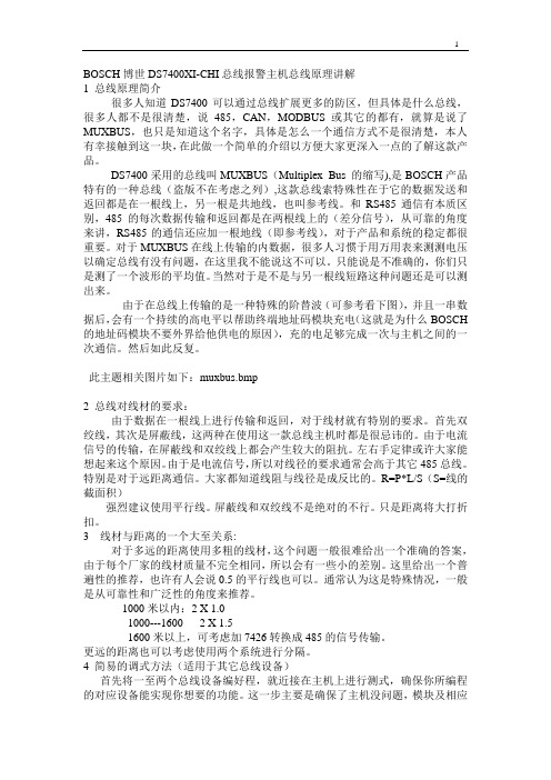
BOSCH博世DS7400XI-CHI总线报警主机总线原理讲解1 总线原理简介很多人知道DS7400可以通过总线扩展更多的防区,但具体是什么总线,很多人都不是很清楚,说485,CAN,MODBUS或其它的都有,就算是说了MUXBUS,也只是知道这个名字,具体是怎么一个通信方式不是很清楚,本人有幸接触到这一块,在此做一个简单的介绍以方便大家更深入一点的了解这款产品。
DS7400采用的总线叫MUXBUS(Multiplex Bus 的缩写),是BOSCH产品特有的一种总线(盗版不在考虑之列),这款总线索特殊性在于它的数据发送和返回都是在一根线上,另一根是共地线,也叫参考线。
和RS485通信有本质区别,485的每次数据传输和返回都是在两根线上的(差分信号),从可靠的角度来讲,RS485的通信还应加一根地线(即参考线),对于产品和系统的稳定都很重要。
对于MUXBUS在线上传输的内数据,很多人习惯于用万用表来测测电压以确定总线有没有问题,在这里我不能说这不可以。
只能说是不准确的,你们只是测了一个波形的平均值。
当然对于是不是与另一根线短路这种问题还是可以测出来。
由于在总线上传输的是一种特殊的阶替波(可参考看下图),并且一串数据后,会有一个持续的高电平以帮助终端地址码模块充电(这就是为什么BOSCH 的地址码模块不要外界给他供电的原因),充的电足够完成一次与主机之间的一次通信。
然后如此反复。
此主题相关图片如下:muxbus.bmp2 总线对线材的要求:由于数据在一根线上进行传输和返回,对于线材就有特别的要求。
首先双绞线,其次是屏蔽线,这两种在使用这一款总线主机时都是很忌讳的。
由于电流信号的传输,在屏蔽线和双绞线上都会产生较大的阻抗。
左右手定律或许大家能想起来这个原因。
由于是电流信号,所以对线径的要求通常会高于其它485总线。
特别是对于远距离通信。
大家都知道线阻与线径是成反比的。
R=P*L/S(S=线的截面积)强烈建议使用平行线。
博士报警系统配置说明
CP516
1
16防区LED键盘,可接多个
后备电池
TP12-7
1
探测器
DS835iT等
各类探测器,开关输出
语音转换芯片(可选)
CC888
1
可录制语音信号,报警后通过电话线路传送,可选
分区管理主键盘(可选)
CP500P
1
可管理控制4个分区
分区管理子键盘(可选)
CP500A
4
可管理控制一个分区
总线制防盗报警系统
BOSCH防盗报警系统简易快速配置表
名称
型号
数量
说明
3.6防区报警系统
3.6防区报警主机
DS3MX/DS6MX
1
键盘一体化,可与DS7400总线通讯
电源供应器
PS002
1
DC 12V
探测器
DS835iT等
各类探测器,开关输出
语音拔号器(可选)
DS110
1
报警后通过电话线路语音传送,可选。
聪明锁(可选)
单防区扩展模块(可选)
DS7457I
连接至总线上,可扩展1个防区,最多可连接240个。
双防区扩展模块(可选)
DS7460
连接至总线上,可扩展2个防区,最多可连接120个。
单防区输入输出模块(可选)
DS7465
连接至总线上,可连接1个防区和1个输出,最多可连接60个。
总线制三技术探测器(可选)
DS7476
RF3212E
1
主机配置该设备后即可连接无线探测器和无线遥控按钮,最多连接16个无线探测器和8个无线遥控器
无线被动红外探测器(可选)
RF920E
可和RF3212E进行无线通讯,最多可接16个
BOSCH报警系统详细介绍及如何使用

DS9370 特点
➢被动红外、微波和人工智能三种技术 合成
➢吸顶式安装,3个PIR探测元件, 360°全方位。
。 ➢ 主机可配套使用CMS7000报警管理软件,通过管理软件可以识别DS6MX
的布撤防信息及其所带6个防区的信息。 ➢ 总线上的模块可以混合使用,系统组织灵活。 ➢ 可以配置联动输出模块灵活实现联动输出。 ➢ 系统有自检功能并通过液晶键盘或管理软件直观显示,方便系统维护
管理。 ➢ 主机可直接连接电话线向报警接收中心发送各类标准格式的报警信息
F 10
e e
5
t0
0 F ee t
15 M 3e
t
e
0r 50 s
O -Q
J -N
A -I
Mirror adjusted t o -3?
Mi rror Seg ment to P attern Reference
P
O
Q
J K LMN
A B CDE F GH I
Optics
SENSOR
一:透镜
➢将变化的红外能量聚焦到探测元件上 ➢可以是反射镜片或菲涅耳透镜 ➢由镜片或透镜上的小刻面来决定 ➢探测区域或角度
➢ 性能 ➢ 多种探测回路探测所有已知的攻击方式 ➢ 多点防拆保护蓄意的破坏 ➢ 优秀的防误报性能 ➢ 先进的信号处理模式 ➢ 表面安装技术 ➢ 优良的防无线干扰
震动探测器的处理
➢ 使用的探测方式 ➢ 钻头, 高温焊割, 切割 ➢ 振幅低/持续时间长的信号 ➢ DS1535 有专门为 ATM机设计的附加过滤功能,能 减少误报
BOSCH 防盗报警系统DS7432 系列 8 防区总线输入模块 说明书

DS7432 系列 8 防区总线输入模块包括 DS7432 和 DS7432E 两种型号。
两种模块均可处理多达 8 路常规触点的输入回路与控制主机的多路复用总线相连。
DS7432E 还提供一个串连双终端电阻 (EOL) 布线配置。
DS7432E 可处理多达 16 路输入触点(每路回路的报警点和防拆点)。
DS7432 每路输入使用一个 47 kΩ电阻。
DS7432E 每路输入使用 22 kΩ + 47 kΩ 电阻。
证书与认可地区认证欧洲CE1999/5/CE Radio Eqipment & TelephoneEquipment Directive (R&TTE)2004/108/EC EMC Directive (EMC),2006/95/EC Low-Voltage Directive (LVD)美国UL DS7432: AMCX: Central Station AlarmUnits (UL1610, UL1635), APAW: PoliceStation Alarm Units (UL365, UL464),UOXX: Control Unit Accessories, System(UL864, 9th edition), UTOU: Control Unitsand Accessories - Household System Type(UL985)CSFM DS7432: 7165-1615: 113, 7165-1615:119NYC-MEA DS7432: 274-94-E, Vol. IVDS7432: 274-94-E, Vol. III 安装/配置兼容性信息DS7432 系列模块只能通过相连的多路复用总线扩展接口连接至下列控制主机。
控制主机D9412GV2 控制主机D7412GV2 控制主机D9412G 控制主机D7412G 控制主机DS7400XiV4 控制主机DS7400Xi 控制主机多路复用总线接口模块D8125MUX 多路复用总线接口模块DS7430 多路复用总线扩展模块DS7436 多路复用总线扩展模块注解当 PCB 的跳线设为 DS7432 模式时,DS7432E 与 D9412GV2、D9412G、D7412GV2 和D7412G 兼容。
BOSCH 防盗报警系统 ISM
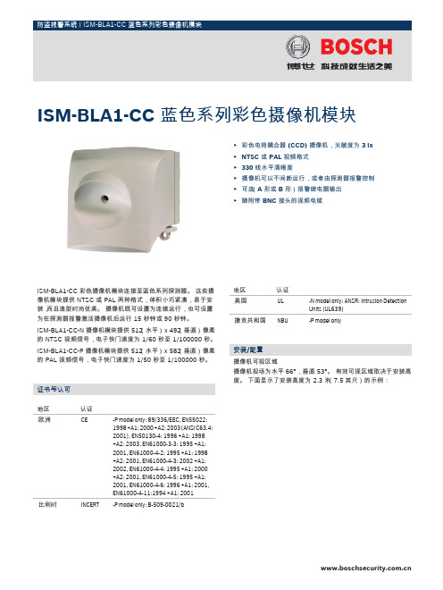
ISM-BLA1-CC 彩色摄像机模块连接至蓝色系列探测器。
这些摄像机模块提供 NTSC 或 PAL 两种格式,体积小巧紧凑,易于安装,而且造型时尚优美。
摄像机既可设置为连续运行,也可设置为在探测器报警激活摄像机后运行 15 秒钟或 90 秒钟。
ISM-BLA1-CC-N 摄像机模块提供 512(水平)x 492(垂直)像素的 NTSC 视频信号,电子快门速度为 1/60 秒至 1/100000 秒。
ISM-BLA1-CC-P 摄像机模块提供 512(水平)x 582(垂直)像素的 PAL 视频信号,电子快门速度为 1/50 秒至 1/100000 秒。
证书与认可地区认证欧洲CE-P model only: 89/336/EEC, EN55022:1998 +A1: 2000 +A2: 2003 (ANSI C63.4:2001), EN50130-4: 1996 +A1: 1998+A2: 2003, EN61000-3-3: 1995 +A1:2001, EN61000-4-2: 1995 +A1: 1998+A2: 2001, EN61000-4-3: 2002 +A1:2002, EN61000-4-4: 1995 +A1: 2000+A2: 2001, EN61000-4-5: 1995 +A1:2001, EN61000-4-6: 1996 +A1: 2001,EN61000-4-11:1994 +A1: 2001比利时INCERT-P model only: B-509-0021/b 地区认证美国UL-N model only: ANSR: Intrusion DetectionUnits (UL639)捷克共和国NBU-P model only安装/配置摄像机可视区域摄像机视场为水平 66°,垂直 53°。
有效可视区域取决于安装高度。
下面显示了安装高度为 2.3 米(7.5 英尺)的示例:ISM‑BLA1‑CC 蓝色系列彩色摄像机模块▶彩色电荷耦合器 (CCD) 摄像机,光敏度为 3 lx▶NTSC 或 PAL 视频格式▶330 线水平清晰度▶摄像机可以不间断运行,或者由探测器报警控制▶可选(A 形或 B 形)报警继电器输出▶随附带 BNC 接头的视频电缆2俯视图1摄像机的可视区域2PIR 探测区域侧视图1摄像机的可视区域2PIR 探测区域3下视区注解被动红外 (PIR) 探测区域和下视区取决于使用的特定探测器。
博世防盗报警产品系统介绍

MT产品:MTGW总线转换模块
➢一端连接CAN总线与MTR通讯 ➢另三端连接RS485总线与DS6R/MT1-8/
MT1-1等终端设备进行通讯 ➢每路RS485总线互相隔离 ➢最多可连接120个RS485终端设备 ➢通过拔码设置CAN总线地址及RS485终端设备数量, 免编程 ➢设有电源/系统/CAN总线/RS485总线四类指示灯, 方便工程人员安装维护 ➢备有机壳及变压器,设有12V备用电池接口及 13.5Vdc@500mA辅助电源输出,并有防拆保护
DS7400XI 附件介绍
DSR-32C 32路继电器输出模块
连接方式一:4线接入DS7400XI主板辅助总线端由报警主机直接控制工作 连接方式二:通过RS232接口直接和电脑连接,由CMS7000软件控制动作 提供32路继电器开路和闭路输出 每台DS7400XI可连接16个DSR-32C,默认可与每个防区一一对应动作 CMS7000软件可设置两个RS232端口连接DSR-32C,最多可连接16台,提 供512个继电器输出控制 可通过自带软件设定跟随一个防区或多个防区输出,或多个防区启动一个继 电器输出 继电器动作可设定手动复位或自动复位 特别适用于需要联动LED电子地图、联动灯光、联动矩阵硬盘录像机或者BA 系统等场合
MUX总线:RVV-4x1.5(最长1500米)
最多120 防 区
防区 输入 模块
探 测 器
输入 输出 模块
用户 键盘
探 测 器
区自 带 防
32路 输出模块
MUX总线:RVV-4x1.5(最长1500米)
最多120 防 区
总线驱 动模块
用户 键盘
输入 输出 模块
防区 输入 模块
DS7400
系统 键盘
博世8防区模块说明书
博世8防区模块说明书一、模块概述:博世8防区模块采用先进的传感技术和信号处理技术,能够准确地检测目标物体并及时报警。
模块具有8个独立的防区输入端口,每个端口可连接一个传感器。
模块内部集成了报警处理电路和通信接口,可将报警信号传输给报警主机或其他安全设备。
二、产品特点:1.多防区输入:模块具有8个独立的防区输入,可以连接各种类型的传感器,如红外线传感器、微波传感器、烟雾传感器等。
2.灵敏度可调:根据实际需要,可以调整每个防区的灵敏度,以适应不同环境下的安全需求。
3.报警方式多样:模块支持多种报警方式,包括声音报警、光闪报警和远程报警等,用户可根据需要选择合适的报警方式。
4.报警处理迅速:模块内部集成了高效的报警处理电路,一旦检测到目标物体越界或异常,模块会立即发出报警信号,确保报警响应的及时性。
5.通信接口丰富:模块具有RS485通信接口,可以与报警主机或其他安全设备进行通信,实现联动报警和信息传输。
三、安装方法:1.安装位置选择:根据需要,选择适合的位置安装模块,建议选取离地面2-3米的位置,以确保传感器的有效监测范围。
2.传感器连接:将传感器与模块的防区输入端口进行连接,确保连接牢固可靠。
3.电源接入:将模块的电源接入电源线路,确保电源的稳定供应。
4.通信接口连接:如需与报警主机或其他安全设备进行通信,可将模块的通信接口与相应设备进行连接。
四、使用方法:1.激活模块:安装完成后,通过设置模块的相关参数,对模块进行激活。
2.参数设置:根据实际需要,设置每个防区的灵敏度、报警方式等参数。
3.监测与报警:模块开始工作后,会实时监测各个防区的状态,并在检测到异常情况时及时发出报警信号。
4.报警处理:一旦发生报警,模块会启动内部的报警处理电路进行处理,并通过通信接口将报警信息传送给报警主机或其他安全设备,用户可以根据实际情况进行处理和处置。
五、注意事项:1.安装时请确保电源接线准确、可靠,避免短路或其他电气问题。
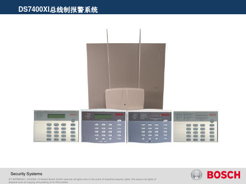
博世DS7400XI报警系统介绍共38页文档
Security Systems
ST-IN/PRM-EU | 3/2/2005 | © Robert Bosch GmbH reserves all rights even in the event of industrial property rights. We reserve all rights of disposal such as copying and passing on to third parties.
DS7400XI的附件介绍:八防区输入扩展模块DS7432
DS7400XI的附件介绍: 总线驱动器DS7436
Security Systems
ST-IN/PRM-EU | 3/2/2005 | © Robert Bosch GmbH reserves all rights even in the event of industrial property rights. We reserve all rights of disposal such as copying and passing on to third parties.
DS7400XI的附件介绍: 液晶控制键盘DS7447
Security Systems
ST-IN/PRM-EU | 3/2/2005 | © Robert Bosch GmbH reserves all rights even in the event of industrial property rights. We reserve all rights of disposal such as copying and passing on to third parties.
DS7400XI主板示意图
博世DS7400XI报警系统介绍
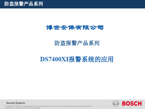
DS7400XI的附件介绍:双防区扩展模块DS7460i
Security Systems
ST-IN/PRM-EU | 3/2/2005 | © Robert Bosch GmbH reserves all rights even in the event of industrial property rights. We reserve all rights of disposal such as copying and passing on to third parties.
Security Systems
ST-IN/PRM-EU | 3/2/2005 | © Robert Bosch GmbH reserves all rights even in the event of industrial property rights. We reserve all rights of disposal such as copying and passing on to third parties.
DS7400XI的附件介绍:八防区输入扩展模块DS7432
Security Systems
ST-IN/PRM-EU | 3/2/2005 | © Robert Bosch GmbH reserves all rights even in the event of industrial property rights. We reserve all rights of disposal such as copying and passing on to third parties.
DS7400XI的附件介绍:单路输入/输出扩展模块DS7465i DS7465i单路输入/输出扩展模块 直接并入两线制总线工作。 每个模块占用总线2个防区地址 提供一个防区输入和一个继电器输出接口
BOSCH博世总线制报警主机DS7400XI智能防盗报警系统解决方案
BOSCH博世总线制报警主机DS7400XI智能防盗报警系统
解决方案
首先,DS7400XI可以连接多种不同类型的传感器和控制器,如红外
探测器、门禁控制器、烟雾报警器等,实现对多种安全事件的监测和响应。
这些传感器和控制器通过总线技术与主机连接,可以实现双向通信和数据
交换,从而提高系统的灵敏度和可靠性。
其次,DS7400XI支持多种报警方式和联动控制策略,可以根据不同
的安全事件触发相应的报警行为,如触发警报器、发送短信通知等。
同时,系统还能够与其他设备和系统进行联动控制,如与监控摄像头联动,实时
监测发生的安全事件。
此外,DS7400XI还具有用户友好的界面和操作方式,可以通过面板、遥控器或者手机App对系统进行操作和监控。
用户可以通过系统设置不同
的安全模式和权限,对不同的用户进行权限控制,保证系统的安全性和可
靠性。
最后,DS7400XI还具有高可靠性和自我监测功能。
该系统具备自我
检测和故障自愈功能,能够实时监测系统的运行状态,并对任何故障进行
自动报警和修复。
系统还支持远程监控和管理,管理员可以通过网络远程
查看系统的实时状态和报警信息,提高了系统的管理和维护效率。
综上所述,BOSCH博世总线制报警主机DS7400XI智能防盗报警系统
解决方案通过总线技术实现多种传感器和控制器的联动和集成,提供了更
高效、可靠的安全保护。
系统具备多种报警方式和联动控制策略、用户友
好的界面和操作方式、高可靠性和自我监测功能,可以满足不同场景下的
安全需求。
bosch联动报警调试报告

调试报告一、要求:对射报警,硬盘录像机上对应的摄像机进行录像。
二、设备:1,博世报警主机DS7400。
2,博世联动报警继电器DSR32C,(输出信号)。
3,中佳报警控制器ZJ1602606Z J A C1。
三,调试步骤;1,DSR23C打开DSR32C上盖板,可以看到说明如下:a,与DS7400连接,JP33设置在TTL;与485设备连接,JP33设置在485。
b,DS7400主机的辅助R/B/G/Y四根线分别接到DSR32A上的相应接线柱上。
接通DSR32A报警继电器输出板的电源,电源指示灯亮,表明电源工作正常。
然后接通DS7400主机的电源,在听到“嘟”一声响后,两只通讯LED灯(TX,TR)开始不断的闪烁,表明报警继电器输出板和DS7400已经通讯正常。
c,当DS7400布防后,若产生报警信号,继电器板上相应的继电器将吸合,同时该继电器相应的LED将亮。
(预置值为一对一;若要多对一、一对多,可用软件进行设置)。
d,通过JP1-JP32跳线器的设置可以对每一个防区报警实现开路或短路输出(预置值为短路输出)。
e,若JP37为开路状态,继电器吸合三秒后将断开。
否则只有通过手动复位开关才能将吸合的继电器断开(预置值为短路)。
注:DS7400 为V4.0以上版本,地址4019编成为11,4020编成为30为V3.0版本,地址0206编成为17,0207编成为30为V4.10版本,地址0341编成为11,0342编成为302,ZJ1602A连线说明:(1) PC DB9端接数字录像机串行口1/串行口2(COM1/COM2)DB9-2脚TXDDB9-3脚RXDDB9-5脚GND(2) 485通讯接口A 串行通信控制信号A输出端;B 串行通信控制信号B输出端;(3) ALM IN 报警控制输入IN1 1#探测器IN2 2#探测器..IN16 16#探测器(4) ALM OUT1第一路报警控制器输出ALM OUT2第二路报警控制器输出(触点:36 V交流/0.5A)ON:常闭端NC:常开端COM:公共端报警输出1DC+12V输出485通讯接口PC 接口COMNO NCCOMNONCA O U T1O UT 2IN16IN15IN14IN13IN12IN11IN10IN9IN8IN7IN6IN5IN4IN3IN2IN1GND+12VGNDBARSTRXDTXDA L M I N 最大0.5A 485P CB ,DSR32C 输出32路,每一路2根线。
博世周界报警系统方案

周界入侵报警系统解决方案目录一、系统综述 (2)二、系统配置 (3)2.1 前端探测器 (3)2.2 前端控制与数据存储设备配置 (3)2.3 系统管理和控制配置 (3)三、系统功能 (4)3.1 系统控制 (4)3.2 报警监视, 显示和事件日记 (4)四、系统结构 (4)4.1 键盘功能 (5)4.2 报警管理中心功能 (5)五、设备技术参数 (5)5.1 报警主机DS7400Xi-CHI (5)5.2 DS7447E-CN 控制键盘 (9)5.3 DS7436 双回路总线驱动器 (10)5.4 DS7457i -CHI 单防区输入模块 (10)5.5 DSR-32C 三十二路继电器模块 (11)5.6 DX4010V2 USB/RS-232接口模块 (12)5.7 报警管理软件MTSW (12)5.8 紧急报警按钮 (14)5.9 室外相对式双光束红外线探测器 (14)一、系统综述本方案中周界入侵报警系统包含总线制报警主机,总线式输入模块,室外相对式双光束红外线探测器、和继电器输出模块等。
室外相对式双光束红外线探测器保护重点是防止有人非法翻越围墙,这些围墙只要有人非法闯入,或者用户触发红外线探测器,设备即会产生报警,报警信号通过总线式输入模块解决后通过系统总线传回至控制中心报警主机,报警主机会按照预先设定的程序通过系统总线迅速传输至前端现场控制总线式输入/输出模块进行联动,启动相应报警点的声光报警器,与此同时控制中心报警管理软件会自动调出电子地图显示报警确切位置,方便中心值班人员及时查看警情事件及报警方位等信息。
入侵报警系统还可以与视频监控系统联动。
当有警情发生时控制中心报警管理软件会自动控制继电器输出模块,将相应报警点信号传输至视频监控系统,实现视频监控管理软件自动弹出相应报警点的监控视频画面。
系统具有防破坏功能,在报警线路被切断或短路,入侵探测器被破坏等情况下均能有效报警。
各子系统配备UPS应急电源,在市电交流电断电2个小时的情况下,系统仍然可以可靠运营。
博世报警系统

博世防盗报警系统
DS7447 V2-CHI 液晶键盘 DS7447 V2-CHI LCD Keypad
• DS7447V2 数字字母键盘:两行文字,显示屏可自由编程, 允许设置 16 个字符的自定义文本来描述防区和分区。 用户
可通过简单易用的双键命令来调整声音报警器的音量和背光
强度。
• DS7447V2 Alphanumeric Keypad: Two line, freely programmable display allows 16 characters of custom text to be programmed for zone and area descriptions. The user can adjust the sounder volume and backlight intensity using easy two-button commands.
normally-open (NO) or normally-closed (NC)
contacts.
STCT/SAL1.2 | Dieter GAO Chuanjian | 23/10/2012 | © Robert Bosch GmbH reserves all rights even in the event of industrial property rights. We reserve all rights of disposal such as copying and passing on to third parties.
博世防盗报警系统
IP7400Xi-CHI 系统基本结构 System Structure
MUX 总线:RVV-2x1.5(最长1500米) MUX Bus: RVV-2x1.5 (Max: 1500 m) 最多120 防区 Max: 120 Zone 总线驱动 模块 Bus Driver 自 带 防 区 键盘 Keypad MUX总线:RVV-2x1.5(最长1500米) MUX Bus: RVV-2x1.5 (Max: 1500 m) 最多120 防区 Max: 120 Zone
博世宝盾(Bosch)安全系统的警报中心连接报警设备说明书

APAW.S1871indicated in the instructions, wiring diagram.Control unit subassemblies, Models D2212B, D2212BE, followed by suffix "LC".Control unit accessories, keypads, Models D202A, D220A, D222A, D223A, may be suffixed by TD; Models D621, D621B, D621W, D623,D623B, D623W, D625, D625B, D625W for use with control panels indicated in the installation instructions.Models D720 and D1255, may be followed by suffixes R, TD or W, for use with control panels indicated in the installation instructions (covered under File S5579); Models D1260, D1260B, D1260R, D1260W, D1260BLK.Control unit subassembly, Model ICP-SDI-9114, for use with control panels and keypads indicated in the installation instructions.Control unit accessories, Models D133, D134 relay modules.Control unit accessory, Model D208 zone expansion module.Control unit subassembly, Model D208LC zone expansion module.Control unit accessories, Models D9210B, D9210BC, D9210BLC access control modules. (Covered under File S5579).Control unit accessories, Models SK-820 Data Repeater, SC9002 Printer (Covered under S5579).Control unit modules, Models SC-4000D, SC-4000DSC, SC-4000 Guard Unit RF transmitters (Covered under S5579).Control unit subassembly, Model LS-500 Line Simulator, Ethernet Module, Model B420 (Covered under S5579).Control unit accessory, Network Interface Module, Model DX4020 (covered under File S5579).Control unit subassembly, GPRS/GSM IP Communicator, Model ITS-DX4020-G (+8).Communicator interface module, Model B450(+12).Control unit accessories, printer interface, Model D9131A. For use with Radionics products where referenced in the installation instructions. Control unit subassemblies, Models D6412LC, D6412M, D4412LC, D4412M, DX2010, DX3010.Control unit subassembly, Ethernet Module, Model B420 (++)(Covered under S5579).Control unit accessory, RF Receiver, Model RF3224. Suitable for use with transmitters indicated in the installation instructions.Models D4412, D4412LT, D6412, D6412LT. For all applications, the Model D8108A or D8108AH, attack resistant enclosure and a Listed local sounding device are required. Suitable for use with Models D621, D621W, D623, D623W, D625, D625W Command Centers. The units may include Listed modules and subassemblies referenced in the manufacturer's operation, installation manual. Suitable for bank safe and vault applications when used in conjunction with the Listed Model S110 Electronic Sounding Device by Rothenbuhler Engineering.Control unit subassembly, C900V2+ dialer capture module.Enclosure, Model ULPS (++).Computer, Model B-010 (+2) for use with receiver model D6600.Monitor, Model B-008 (+3).Digital alarm communicator receiver, Model 6100IPv6. The Model 6100IPv6 Connettix Receiver is suitable for use as a commercial DACR and PSDN communicator.Control unit accessory, Model ISW-D8125CW-V2 (+7) wireless Interface module for use with separately Listed ISW-EN-4200 Wireless Inovonics RF Receiver. Compatible with control panels D9412GV3/D7412GV3/D7212GV3, D9412GV2/D7412GV2, D7212GV2.Subassembly, Model B46 Communicator Status Indicator (+17).Model B465 Connettix Universal Dual Path Communicator (+17).+ - Complementary Listed to AMCX, AMCX7, UTOU, UTOU7, NBSX, NBSX7, APAW7, APOU, APOU7.++ - Complementary Listed to ALVY, AMCX, AOTX, APOU, NBSX, UOXX, UTOU.(+2) - Complementary Listed to UOJZ, UOJZC, AMCX7, APAW7, APOU, APOU7.(+3) - Complementary Listed to UOXX, UOXXC, AMCX7, APAW7, APOU, APOU7.(+4) - Complementary Listed to AMCX, AMCX7, APAW7.(+5) - Suitable for Encrypted Line Security when employing Listed Models DX4020 or C900V2 via PSDN only.(+6) - Complementary Listed to UOJZ, AMCX, APOU, ALVY, AOTX, NBSX, UTOU.(+7) Complimentary Listed to APOU, AMCX, UTOU, AOTX, NBSX.(+8) Complimentary Listed to UOJZ, AMCX, UTOU, NBSX, APOU.(+9) Complimentary Listed to UOJZ, APOU, AMCX, APAW, ALVY, AOTX, UTOU, NBSX, AMTB, ANET, Suitable for Encrypted Line Security when employing Listed Models DX4020 or C900V2 via PSDN only.(+10) Complimentary Listed to UOJZ, APOU, AMCX, APAW, ALVY, AOTX, UTOU, NBSX, AMTB, ANET, Suitable for Encrypted Line Security when employing Listed Models DX4020 or C900V2 via PSDN only.(+11) Complimentary Listed to APOU, APOU7, AMCX, AMCX7, AOTX, AOTX7, APAW7, UTOU, UTOU7, NBSX, NBSX7, AMTB, ANET.(+12) Complementary Listed to UOJZ, AMCX, AMCX7, APAW7, APOU, APOU7, AOTX, AOTX7, UTOU, NBSX, AMTB, ANET.(+13) Complementary Listed under AMCX, AMCX7, AMTB (ANSI/SIA CP-01-2010), ANET, AOTX, AOTX7, APAW7, APOU, APOU7, NBSX, NBSX7, UTOU, UTOU7.(+14) Complementary Listed under AMCX, AMCX7, AMTB, ANET, AOTX, ATOX7, APAW7, APOU, APOU7, NBSX, NBSX7, UTOU, UTOU7, UOJZ, ANSI/SIA CP-01-2010.(+15) Complementary Listed under AMCX, AMTB, ANET, AOTX, APOU, NBSX, UTOU, ANSI/SIA CP-01-2010.(+16) Complimentary Listed to APOU, APOU7, AMCX, AMCX7, AOTX, AOTX7, APAW7, UOJZ, UTOU, UTOU7, NBSX, NBSX7, AMTB, ANET.(+17) Complementary Listed under AMCX, AMCX7, AMTB, ANET, AOTX, ATOX7, APAW7, APOU, APOU7, NBSX, NBSX7, UTOU, UTOU7, UOXX, ANSI/SIA CP-01-2010.Model StandardLineSecurityEncryptedLineSecurityNo LineSecurityConditions andNotesD6600 Netcom Receiver X——when used with compatible control unitD6600 Netcom Receiver—X—when used with a compatible control unit and ListedModel DX4020 Network Interface Module or the Listedmodel C900V2 Dialer Capture Module along with theD6680 network adapter.D6500 Digital AlarmCommunicator Receiver——X—D7412, D9412GV2, D7412GV2,D7212GV2, D9412GV3,D7412GV3, D7212GV3 DACTUnitsX———B3512, B4512, B5512 Control Units X——With onboard IP connection, B426 module, B440,B441, B442 or B443 cellular communication modulewith Bosch Listed D6600 or D6100IPv6B8512G(+16), B8512G-E (+16), B9512G (+16), B9512 (+16)—X—With onboard IP connection, B426 module, B440,B441, B442 or B443 cellular communication modulewith Bosch Listed D6600 or D6100IPv6B3512, B4512, B5512 ControlUnits——X When using B430 DACT communication moduleB8512G(+16), B8512G-E(+16), B9512G (+16), B9512(+16)——X When using B430 DACT communication moduleD7412, D9412GV2, D7412GV2, D7212GV2, D9412GV3,D7412GV3, D7212GV3 DACT Units —X—when used with Listed Models DX4020 or C900V2 viaPSDN onlyD2212B, D2212BE(may be followed by suffix "LT") Control Units —X—when used with Listed model C900V2 Dialer CaptureModule for use with receivers as indicated in theinstallation instructionsD4412, D4412LT, D6412, D6412LT Control Units —X—when used with the model C900V2 dialer capturemodule for use with receivers as indicated in theinstallation instructionsD6100IPv6 Digital AlarmCommunicator Receiver—X——ITS-DX4020-G X X—When used with Bosch control panels, modelsD9412GV2, D7412GV2, D7212GV2, D9412GV3,D7412GV3, D7212GV3, and Bosch receivers, modelsD6600 and D6100I.Trademark and/or Tradename: "Safecom"。
BOSCH博世总线制报警主机DS7400XI智能防盗报警系统解决方案
BOSCH博世总线制报警主机DS7400XI智能防盗报警系统解决方案某大型工厂有 5 个厂区,分布比较分散,厂区之间通过光纤布了局域网。
厂方现在要求对每个厂区安装防盗报警系统,在管理中心进行集中管理。
根据该项目的具体设计要求和实际情况,该系统采用了 BOSCH 公司的大型报警系统,该系统采用了一切有效的探测手段,使用第 l 节防盗报警系统的设计思想1.1 系统设计指导思想某大型工厂有 5 个厂区,分布比较分散,厂区之间通过光纤布了局域网。
厂方现在要求对每个厂区安装防盗报警系统,在管理中心进行集中管理。
根据该项目的具体设计要求和实际情况,该系统采用了 BOSCH 公司的大型报警系统,该系统采用了一切有效的探测手段,使用总线扩展的方式来达到系统的可扩展性和易操作性,利用工厂的局域网将主机连接起来,使用多媒体 PC 机对系统进行有效的管理,并可实现与视频和 BA 系统的联动。
1.2 系统方案特点1.2.1 系统中的前端探测器共分六类:三技术探测器,玻璃破碎探测器,震动探测器,对射探测器,烟感探测器,幕帘探测器和防抢按钮。
1.2.2 防盗报警系统与电视监控系统实现报警联动控制功能。
1.2.3 防盗报警系统与 BA 系统实现灯光联动控制功能。
1.2.4 每个区的报警系统可独立操作互不影响。
1.2.5 通过管理软件可直观显示系统状态,一有报警即刻有电子地图和声音提示。
1.2.6 系统大容量,并采用总线制方式,操作简便,可扩展性较强。
1.2.7 每个厂区用一个 DS7400XI 主机,通过 RS232/TCPIP 转换器实现与局域网的连接。
第 2 节防盗报警系统的组成2.1 设备选型采用德国 BOSCH 公司的防盗报警控制设备和探测器。
2.2 系统组成本方案中防盗报警系统由前端探测器、信号传输、控制以及联网通信部分组成。
2.2.1 前端探测器本系统一共采用了 8 种探测器:幕帘式被动红外探测器 DS920I ,三技术探测器 DS970 ,吸顶式三技术探测器 DS9370 ,四光束红外对射探测器 DS453Q ,玻璃破碎探测器 GBS210 ,震动探测器 ISN-SM-50 ,光电式烟感探测器SD-212SP 以及防抢按钮。
Bosch报警技术方案
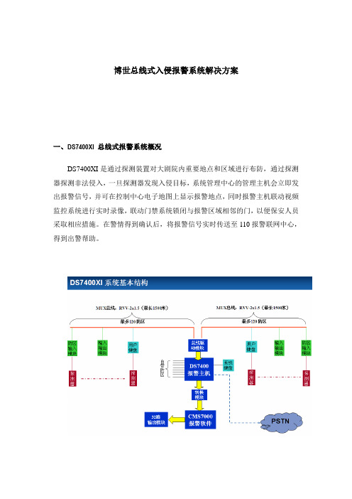
博世总线式入侵报警系统解决方案一、DS7400XI 总线式报警系统概况DS7400XI是通过探测装置对大剧院内重要地点和区域进行布防,通过探测器探测非法侵入,一旦探测器发现入侵目标,系统管理中心的管理主机会立即发出报警信号,并可在控制中心电子地图上显示报警地点,同时报警主机联动视频监控系统进行实时录像,联动门禁系统锁闭与报警区域相邻的门,以便保安人员采取相应措施。
在警情得到确认后,将报警信号实时传送至110报警联网中心,得到出警帮助。
二、系统需求根据大剧院的建筑特点,系统防范重点在主要出入口、库房等区域设置双鉴探测器,在残疾人卫生间设置声光报警器和紧急按钮。
本系统由报警主机,编程键盘,总线扩展模块,八防区输入模块,双鉴探测器、声光报警器、紧急按钮,系统软件组成。
编程键盘用于对每个防区编程,定义防区功能,对防区撒/布防。
双行LCD 屏可显示系统状态,警报提示。
总线扩展模块用于给主机提供总线防区扩展,内置于DS7400XI主板上。
连接各种防区输入模块。
八防区输入模块可能提供8个总线式防区,连接双鉴探测器、声光报警器、紧急按钮等设备。
系统软件用于对DS7400XI可直接管理,集通讯、报警信息管理、用户资料管理、备份、巡更管理、地图显示为一体的专业管理软件。
可以转发报警信息,联动处理。
三、系统功能DS7400XI设计采用总线制结构,每一个现场报警设备均有各自独立的地址,当发生非正常事件报警时,系统能够自动识别报警来源,并在电子地图上显示出报警区域位置,同时声光报警器发出报警声光提醒保卫人员及时处理警情;保卫人员可以在报警主机根据不同时段需要进行布防、撤防等操作,可以在电子地图进行相应的操作。
报警管理软件具有报警信息的记录、统计、打印报表等相应功能。
不同用户的实际情况影响构成系统的规模和功能,但是按输入、控制、输出来区分,其功能结构不外乎是以下三部分:1、前端探测器:探测器是系统的输入部分,各种类型的探测器用不同的手段探测各种入侵行为,常用的探测器有双鉴探测器、红外探测器、幕帘探测器、门磁探测器、玻璃破碎探测器、煤气泄漏探测器、周界红外对射探测器和紧急按钮等等,系统将所得信号进行一些逻辑判断,发出警报。
博世火警系统 FPA-5000 与功能模块 FPA-5000 与功能模块 www.boschsecu
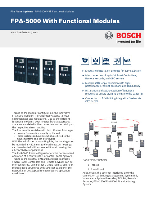
u Modular configuration allowing for easy extensionu Interconnection of up to 32 Panel Controllers,Remote Keypads, and OPC serversu Multiple CAN loop connection with high-performance Ethernet backbone and redundancyu Installation and auto-detection of functionalmodules by simply plugging them into the panel railu Connection to BIS Building Integration System viaOPC serverThanks to the modular configuration, the innovativeFPA‑5000 Modular Fire Panel easily adapts to localcircumstances and regulations. Due to the differentfunctional modules, country-specific characteristicsare accommodated in the connection just as quickly asthe respective alarm handling.The fire panel is available with two different housings:•Housing for mounting directly on the wall•Frame installation housings which are fitted to themounting frame and can be swiveledWith the aid of special mounting kits, the housings can be mounted in 482.6 mm (19") cabinets. All housingscan be extended with various additional housings for all conceivable applications.The FMR‑5000 Remote Keypad offers the decentralized operation of a control panel or control panel network. Thanks to the external CAN and Ethernet interfaces, several Panel Controllers and Remote Keypads can be interconnected. Using either a single‑loop structure or multiple‑loop structures with Ethernet backbone, the network can be adapted to nearly every application conditions.CAN CANCANCAN/Ethernet Network1Fire panel2Remote KeypadAdditionally, the Ethernet interfaces allow the connection to: Building Management System BIS, Voice Alarm System Praesideo/PAVIRO, Remote Services, FSM-2500/FSM-5000 Fire Monitoring System.FPA-5000 systems can be connected to the Bosch UGM Universal Security System and thus, be integrated into a large network system.The entire fire detection system is configured via a laptop using the FSP-5000-RPS Programming Software.Pos.DescriptionA Functional ModulesB Address Cards / Licencse KeysC Panel ControllerD Distributor, optionalE Panel Rail ShortF Power Supply Bracket (installed in Frame Installation Housingsex-works)G Power SupplyH Housing (in this case HCP 0006 A)I Panel Rail Long L BatteriesM Remote KeypadOperation / processing of messagesThe operation and the processing of all messages are easy and intuitive thanks to the ergonomically-designed control panel with its TFT touch‑screen offering a menu-driven handling and multi-color display. To that end, there are permanently located keys on the right, bottom, and upper edge of the display as well as variably located virtual keys in the touch-screen area.Modular StructureDue to its modular structure, the FPA-5000 Modular Fire Panel provides complete flexibility and thus customized solutions for any application. Depending on the requirements, the following selection can be made when planning:1.Housing type: Frame installation or wall-mount–Selection of a basic housing–Optional Extension Housings–Optional Power Supply Housings–Optional kits for installation in 48 cm (19'') racks 2.Operating and Display Unit with Panel Controller–Selection from the various language variants3.Panel Rail–Selection according to housing type and/ornumber of required functional modules4.Functional modules–Selection based on planning and country-specific requirements5.Power supply–Batteries–Additional power supply facilities–Power Supply Brackets are preinstalled ex-works for Frame Installation Housings–For Wall-mount Housings, Power Supply Brackets are selected as needed6.Additional accessories–Front Doors–Printer with Frame Installation Housing–Cable Sets for special applicationsModulesThe functional modules are autonomous, encapsulated units that can be inserted into any control panel slot using plug-and-play technology. Thus, the power supply and the data traffic to the control panel are indicated automatically without any additional settings. The module is automatically identified by the control panel and functions in the default operating mode.Wiring to external components is performed using compact connector/screw terminals.After a replacement, only the connectors need to be reinserted; extensive rewiring is no longer required.NetworkingUp to 32 Panel Controllers, Remote Keypads and OPC server can be interconnected within a network. Depending on the application requirements, Panel Controllers and Remote Keypads can be grouped,defined as network node or local node. Within a group, only panel conditions of the same group can bedisplayed. Regardless of the groups, network nodes allow for the display and handling of all panelconditions. Local nodes display the conditions of the related panel.When networking via CAN and/or Ethernet interfaces, the following connection topologies are optional:•Redundant loop via CAN1 and CAN2 (max. 32 nodes)•Ethernet loop (max. 32 nodes)•Multiple CAN loops with Ethernet backbone and up to32 nodesFor networking with optical fibers, you can use various converters. For detailed information on suitable converter types and maximum line lengths, refer to the FPA-5000 Networking Guide (available for download). Detection PointsThe Address Cards activate detection points. TheFPA-5000 governs up to 4096 detection points.Each element and input which is able to set off analarm requires a detection point.Inputs are considered as detection points if they areprogrammed accordingly in the FSP-5000-RPS Programming Software.This applies to all manual call points and automatic detectors as well as to the following modules and interfaces because of their inputs:Modules Detection PointsCZM 0004 A up to 4IOP 0008 A up to 8RMH 0002 A up to 2ENO 0000 B requires 1 detection point only if a FSErelease element is connected andprogrammed using the FSP-5000-RPSprogramming softwareFPP‑5000‑TI2Interface modules Detection PointsFLM-420/4‑CON up to 2FLM-420-I8R1-S up to 8FLM-420-I2up to 2FLM-420-O8I2-S up to 2FLM-420-O1I1up to 1FLM-420-RHV Up to 2FLM-420-RLE-S up to 2Certifications and approvalsThe provided options according to EN 54‑2:1997/A1:2006 include:•Output to fire alarm devices•Control of fire alarm routing equipment–Output to fire alarm routing equipment–Alarm confirmation input from fire alarm routing equipment•Outputs to fire protection equipment –Output type A –Output type B –Output type C–Fault monitoring of fire protection equipment •Delays to outputs•Dependencies on more than one alarm signal –Type A dependency –Type B dependency •Alarm counter•Fault warning condition–Fault signals from points–Total loss of the power supply–Output to fault warning routing equipment •Disabled condition–Disablement of adressable points •Test conditionInstallation/configuration notes•Country-specific standards and guidelines must be considered during planning.•Connection conditions for the regional authorities and institutions (police, fire service) must be maintained.•It is preferable to use the loop formation owing to the greater security of loop lines compared with stub lines.•Consider the system limit for the number of LSN elements.•It is possible to combine LSN interface modules and LSN detectors on one loop or stub line.•For a mixed connection of LSN classic elements and LSN improved elements, a maximum of 127 elements are permitted.•Existing conventional detectors can be connected to a CZM 0004 A module. A CZM 0004 A module provides four DC primary lines (zones).•In accordance with EN 54-2, control panels with more than 512 detectors / call points must be connected redundantly. To that end, a second basic housing with a second MPC Panel Controller is used.•For operation of the fire detection system according to EN 54-13, it is necessary to terminate every stub and T-tap with EOL-modules.General System LimitsSystem Limits Functional ModulesSystem Limits for each LSN 0300 A Module•Up to 254 LSN improved version elements or 127classic LSN elements can be connected •Output current–LSN 0300 A: up to 300 mA –LSN 1500 A: up to 1500 mA •Cable length–LSN 0300 A: up to 1600 m –LSN 1500 A: up to 3000 m •Unshielded cables can be usedNoticeOwing to the Planning Software by Bosch, the planning of fire panels in compliance with the limits (e.g. concerning cable length and power supply) is quick and easy.Installation Notes•Fire panels can only be installed in dry, clean interior rooms.•To ensure optimum battery service life, the control panel should only be operated at sites with normal room temperatures.•The following environmental conditions must be noted:–Permissible ambient temperature: -5 °C – 50 °C–Permissible relative humidity: Max. 95 %, non-condensing•Operating and display elements should be located at eye level.•Frame installation housings require at least 230 mm free space on the right next to the last housing; this space is for swiveling out the attached housing for connection, maintenance, and service.•Sufficient space should be left underneath and nextto the control panel for any possible extensions, e.g.for an additional power supply or an extension housing.•Do not operate devices showing condensation.•Only use the mounting materials specified byBOSCH ST. Interference resistance cannot otherwise be guaranteed.•If connected to a Building Management System (BIS Bosch Building Integration System) via the Ethernet and an OPC server, please verify with the responsible network administrator that in case of a network spanning multiple buildings:–the network is designed for connections across multiple buildings (e.g. no interference by different potentials of the ground connection)–all users are assigned to the networkTechnical specifications General System LimitsOrdering informationBCM-0000-B Battery controller modulemonitors the power supply of the fire panel and the charging of the batteriesOrder number BCM-0000-B ANI 0016 A Annunciator module displays the status of 16 individually programmable detection pointsOrder number ANI 0016 ALSN 0300 A LSN bus module, 300mAfor connecting an LSN loop with up to 254 LSNimproved elements or 127 classic LSN elements, with a maximum line current of 300 mAOrder number LSN 0300 ALSN 1500 A LSN bus module, 1500mAfor connecting an LSN loop with up to 254 LSN improved elements with a maximum line current of 1500 mA, or with up to 127 classic LSN elements, with a maximum line current of 300 mAOrder number LSN 1500 AFPE-5000-UGM Module interface to UGMfor connecting the fire panels FPA‑5000 and FPA-1200 to superordinate systems (UGM 2020, FAT 2002/RE, FSM‑2000)Order number FPE-5000-UGMCZM 0004 A Conventional zone modulefor connecting conventional peripherals; provides four monitored conventional linesOrder number CZM 0004 AIOS 0020 A Communication module, 20mAprovides one interface of each S20 and RS232Order number IOS 0020 AIOS 0232 A Communication module, RS232for connecting two devices, e.g. voice alarm system Plena, a laptop or a printer, via two independent serial interfacesOrder number IOS 0232 AENO 0000 B External notification modulefor connecting fire service equipment in compliance with DIN 14675Order number ENO 0000 BCPA 0000 A Cable set panel control to analog transm Used to connect an AT 2000 to the MPC and the ENO 0000 B.Order number CPA 0000 AIOP 0008 A Input-output modulefor individual displays or flexible connection of various electrical devices, providing eight independent digital inputs and eight open collector outputsOrder number IOP 0008 A RML 0008 A Relay module low-voltageprovides 8 change-over contact relays (type C) for low voltageOrder number RML 0008 ARMH 0002 A Relay module high-voltageprovides 2 change-over contact relays (type C) for high voltage, for monitored connection of external elements with feedbackOrder number RMH 0002 ANZM 0002 A Notification appliance zone modulefor connecting 2 separate notification appliance zone lines, provides 2 monitored primary linesOrder number NZM 0002 AAccessoriesFLM-320-EOL2W End-of-line module, 2-wirefor EN 54‑13 compliant termination of conventional linesOrder number FLM-320-EOL2WFLM-420-EOL2W-W End-of-line module 4-wire LSN wall-mountfor EN 54‑13 compliant termination of LSN stubs or T-tapsOrder number FLM-420-EOL2W-WFDP 0001 A Dummy coverFor available module slotsOrder number FDP 0001 APSK 0001 A Lettering strip for keys20 sheets each with 6 strips, printable,for the functional modules BCM‑0000‑B, LSN 0300 A, LSN 1500 A, CZM 0004 A, NZM 0002 A, RMH 0002 A, CTM 0002 A and ENO 0000 BOrder number PSK 0001 APSL 0001 A Lettering strip for LEDs20 sheets each with 10 strips, printable, for theANI I0016 A Annunciator ModuleOrder number PSL 0001 ARepresented by:Europe, Middle East, Africa:Germany:North America:Asia-Pacific:Bosch Security Systems B.V.P.O. Box 800025600 JB Eindhoven, The Netherlands Phone: + 31 40 2577 284****************************** Bosch Sicherheitssysteme GmbHRobert-Bosch-Ring 585630 GrasbrunnGermanyBosch Security Systems, Inc.130 Perinton ParkwayFairport, New York, 14450, USAPhone: +1 800 289 0096Fax: +1 585 223 9180*******************.comRobert Bosch (SEA) Pte Ltd, Security Systems11 Bishan Street 21Singapore 573943Phone: +65 6571 2808Fax: +65 6571 2699*****************************© Bosch Security Systems 2018 | Data subject to change without notice 1218214923 | en, V36, 11. Jun 2018。
BOSCH报警系统详细介绍及如何使用PPT课件

动态分析 II 信号处理(MAP II)
处理信号特别的 “特征” 使用多个临界位来测量信号振幅、极性和持续时间之间的复杂 关系
Puls e Dur ati on
1) Amplitude 2) Timing 3) Polarity
+
+
+ Alarm Th reshold
–
–
Alarm Th reshold
上海冠林银保科技有限公司
BOSCH报警系统技术介绍
Bosch Security Systems
报警系统组成
前端探测器
被动红外探测器 主动红外探测器 震动感应探测器 玻璃破碎震动探测器 烟雾感应探测器 门窗磁开关 紧急按钮
中心控制主机
被动红外的工作原理
原理一:所有固态的物体的温度在超过绝对温度(-459°F or -273°C)后会发射红外能量。
独有的室外三技术探测器,微波及红外 和微处理技术.可靠性高.
动态分析(MAPⅡ)信号处理技术,线性 移动探测技术,抗环境干扰能力强.
可设置DAY/NIGHT模式,白天解除,夜晚 工作
可选择AND/OR模式,根据需要设置安全 模式.
CCC、UL认证
DS720i 长距离三技术探测器
DS小区报警系统是基于专业总线形式的报警系统。
DS7400XI控制主机功能介绍
DS7400XI控制主机功能介绍
主机自带8个防区,可通过总线扩展240个防区。 主机可分成独立工作的8个分区,最多可连接15个操作管理键盘。 总线防区可以通过单防区模块、双防区模块、8防区模块扩展。 主机可通过串行通讯模块连接PC机等串行设备,方便系统集成和管理。 主机可配套使用CMS7000报警管理软件,通过管理软件可以识别DS6MX
- 1、下载文档前请自行甄别文档内容的完整性,平台不提供额外的编辑、内容补充、找答案等附加服务。
- 2、"仅部分预览"的文档,不可在线预览部分如存在完整性等问题,可反馈申请退款(可完整预览的文档不适用该条件!)。
- 3、如文档侵犯您的权益,请联系客服反馈,我们会尽快为您处理(人工客服工作时间:9:00-18:30)。
德国博世报警系统联动模块,DSR-32C总线继电器输出板
DSR-32C是一个总线继电器输出板包含有32个继电器输出终端,它们的报警输出(短路或开路)可以通过设置内部的跳针来控制当DSR-32C连接到一个主机上,这些输出可以由主机来控制,而且可以设置为一对一、一对多或多对一。
品牌:博世BOSCH
型号:DSR-32C
◆直接连接DS7400xi报警主机.实现警报联动输出。
◆直接连接DS7240报警主机。
实现警报联动输出。
◆连接运行CMS7000或M下SW软件的PC。
实现警报联动输出。
◆连接MT 系统.使用MTSW软件.实现继电器输出控制。
◆功能1,或功能2, 或功能4可以和功能3同时使用。
◆使用上述1 .2, 3功能时.可设定一对多或多对一的联动方式。
规格:
◆产品名称32路继电器模块
◆工作电源电压DC12V-15V
◆输入电源电压AC100V-240V
◆电器功耗MAX: 15W, MIN: 0.5W
◆继电器触点负载(阻性) 1 A 240V AC,触点接触电阻(l00mΩ)
◆工作温度0 C-50 ℃
◆产品重量2.85KG
◆产品尺寸432*180*52mm(不包含继电器输出端子和RS232接口)
◆产品结构金属外壳
◆可以应用在DS7400Xi-CHI和DS7240控制主机上
◆一个电源LED指示灯和32个继电器LED指示灯
◆自动或手动继电器复位
◆输出
◆电流(220VAC时)电流为1A
◆接点电阻< 100mW
◆电源要求
◆功率< 30W
◆电压(输入)220 ± 10%VAC
主营产品:
RS485总线制联网报警、TCP/IP网络联网报警、110电话联网报警、RS485总线制温湿度报警控制器、TCP/IP温湿度报警控制器、迷你型温湿度报警探测器、外置式温湿度报警器、可控制降温/除温/加温微开关变送器、机房服务器声光告警系统、机房断电报警系统、博世(BOSCH)防盗报警系列、周界报警系统主动红外对射探测器、壁挂/吸顶/双鉴被动式红外探头、报警一系列配件。
