UF20C05C-G中文资料
F20C20中文资料

MOSPEC F20C05 Thru F20C20 SwitchmodeDual Fast Recovery Power RectifiersDesigned for use in switching power supplies. inverters and as freewheeling diodes. These state-of-the-art devices have the followingfeatures:Glass Passivated chip junctionsLow Reverse Leakage CurrentFast Switching for High Efficiency150¢J Operating Junction TemperatureLow Stored Charge Majority Carrier ConductionLow Forward Voltage , High Current CapabilityPlastic Material used Carries Underwriters LaboratoryFlammability Classification 94V-OMAXIMUM RATINGSF20CCharacteristic Symbol05 10 15 20UnitPeak Repetitive Reverse Voltage Working Peak Reverse Voltage DC Blocking Voltage V RRMV RWMV R50 100 150200 VRMS Reverse Voltage V R(RMS) 35 70 105 140 V Average Rectifier Forward CurrentPer Leg T C=125¢J Per Total Device I F(AV)1020APeak Repetitive Forward Current(Rate V R, Square Wave, 20kHz)I FM 20 ANon-Repetitive Peak Surge Current(Surge applied at rate load conditionshalfware, single phase, 60Hz)I FSM 175 AOperating and Storage JunctionTemperature RangeT J , T stg-65 to +150 JELECTRIAL CHARACTERISTICSF20CCharacteristic Symbol05 10 15 20UnitMaximum Instantaneous Forward Voltage( I F=10 Amp T C = 25¢J) V F 1.30 V Maximum Instantaneous Reverse Current( Rated DC Voltage, T C = 25¢J) ( Rated DC Voltage, T C = 125¢J) I R10200uAReverse Recovery Time( I F = 0.5 A, I R =1.0 , I rr =0.25 A )T rr 150 nsTypical Junction Capacitance(Reverse Voltage of 4 volts & f=1 MHz) C P 55 P FFAST RECOVERYRECTIFIERS20 AMPERES50-200 VOLTSTO-220ABMILLIMETERSDIMMIN MAXA 14.68 15.32B 9.78 10.42C 5.02 6.52D 13.06 14.62E 3.57 4.07F 2.42 2.66G 1.12 1.36H 0.72 0.96I 4.22 4.98J 1.14 1.38K 2.20 2.98L 0.33 0.55M 2.48 2.98O 3.70 3.90F20C05 Thru F20C20FIG-3 FORWARD CURRENT DERATING CURVEA V E R A G E F O R W A R D R E C T I F I E D C U R R E N T (A m p .)LEAD TEMPERATURE (¢J )FIG-4TYPICAL JUNCTION CAPACITANCEJ U N C T I O N C A P A C I T A N C E (P F )REVERSE VOLTAGE (Volts.)FIG-5PEAK FORWARD SURGE CURRENTP E A K F O R W A R D S U R G E C U R R E N T (A m p .)NUMBER OF CYCLES AT 60 HzFIG-1 TYPICAL FORWARD CHARACTERISITICSA V E R A G EF O R WA R D R E C T I F I E D C U R R E N T (A m p .)FORWARD VOLTAGE (Volts)FIG-2 TYPICAL REVERSE CHARACTERISTICSI N S T A N T A N E O U S R E V E R S E C U R R E N T (u A .)PERCENT OF PEAK REVERSE VOLTAGE (¢M )Set time base for 20/50 ns/cmFIG-6 Reverse Recovery Time Characteristic and Test Circuit Diagram。
SMS05C中文资料
110 100
90 80 70 60 50 40 30 20 10
0 0
25
50
75
100
125
150
Ambient Temperature - TA (oC)
Clamping Voltage vs. Peak Pulse Current
Clamping Voltage - VC (V)
45
40 SMS24C
Non-Repetitive Peak Pulse Power vs. Pulse Time
10
Peak Pulse Power - PPP (kW)
1
0.1
Percent of IPP
0.01 0.1
110 100
90 80 70 60 50 40 30 20 10
0 0
1
10
100
Pulse Duration - tp (µs)
SMS15C Parameter
Reverse Stand-Off Voltage Reverse Breakdown Voltage Reverse Leakage Current Clamping Voltage Clamping Voltage Junction Capacitance
Symbol VRWM VBR IR VC VC Cj
Minimum
It = 1mA
6
VRWM = 5V, T=25°C
IPP = 5A, tp = 8/20µs
IPP = 24A, tp = 8/20µs
Between I/O Pins and Gnd
VR = 0V, f = 1MHz
Typical 325
2SC4250中文资料(toshiba)中文数据手册「EasyDatasheet - 矽搜」

反向传输电容 过渡频率 转换增益 噪声系数
(Ta = 25°C)
符号
测试条件
ICBO IEBO V (BR) CEO hFE Cre
fT Gce NF
VCB = 25 V, I E = 0 VEB = 3 V, I C = 0 IC = 1毫安,我B = 0 VCE = 10 V, I C = 5毫安 VCB = 10 V, I E = 0, f = 1兆赫 VCE = 10 V, I C = 5毫安 VCC = 12 V, f = 200兆赫,女 L = 260兆赫 (图1)
• 请联系您的东芝销售代表了解详细信息,以环境问题,如产品的RoHS指令的兼容性. 请遵守产品使用与规范纳入或使用受控物质,包括但不限于,欧盟RoHS指令的所有适用的法律和法规.东芝对发生违规作为适用的法律和法规而导致的损害 或损失不承担任何责任.
5
2007-11-01
• 东芝公司及其子公司和附属公司(统称为“TOSHIBA”),保留这份文件中更改信息的权利,以及相关的硬件,软件和系统(统称为“产品”),恕不另行通 知.
• 本文档以及任何信息均不得转载未经东芝事先书面许可.即使 东芝的书面许可,复制是允许的,只要在没有任何改动/遗漏.
• 虽然东芝的作品不断地提高产品的质量和可靠性,产品会发生故障或失败.客户 负责符合安全标准和用于提供充分的设计和保障其硬件,软件和 这最大限度地降低风险,并避免出现在产品的故障或失效可能导致生命丧失,身体系统 人身伤害或财产损失,包括数据丢失或损坏.在创作和制作的设计和使用,客户必须 也指,符合(一)中的所有相关信息,东芝的最新版本,包括但不限于本文件, 规格,数据表和应用笔记产品的注意事项和条件中规定的“TOSHIBA 半导体可靠性手册“和(b)对于该产品将与或使用的应用程序的说明.客户全权负责自己的产品设计或应用程序的各个方面,包括但不限于:(a)确定 的利用这样的设计或应用该产品的适当性; (b)评价和确定本文档中包含的任何信息的适用性,或图表,图表,程序,算法,示例应用电路,或 任何其他引用文件; (三)验证这样的设计和应用的所有运行参数.
C8051f020中文资料

C8051F020与80C51单片机的异同点来源:世界电子元器件作者:时间:2007-06-05发布人:卢春妙1引言80C51系列单片机及其衍生产品在我国乃至全世界范围获得了非常广泛的应用。
单片机领域的大部分工作人员都熟悉80C51单片机,各大专院校都采用80C51系列单片机作为教学模型。
随着单片机的不断发展,市场上出现了很多高速、高性能的新型单片机,基于标准8051内核的单片机正面临着退出市场的境地。
为此,一些半导体公司开始对传统8051内核进行大的构造,主要是提高速度和增加片内模拟和数字外设,以期大幅度提高单片机的整体性能。
其中美国Cygnal公司推出的C8051F系列单片机把80C51系列单片机从MCU时代推向SoC时代,使得以8051为内核的单片机上了一个新的台阶。
C8051F系列单片机是完全集成的混合信号系统级芯片,具有与8051兼容的CIP-51微控制器内核,采用流水线结构,单周期指令运行速度是8051的12倍,全指令集运行速度是原来的9.5倍。
熟悉NCS-51系列单片机的工程技术人员可以很容易地掌握C8051F的应用技术并能进行软件的移植。
但是不能将8051的程序完全照搬的应用于C8051F单片机中,这是因为两者的内部资源存在较大的差异,必须经过加工才能予以使用。
其中C8051F020以其功能较全面,应用较广泛的特点成为C8051F的代表性产品,其性能价格比在目前应用领域也极具竞争力。
C8051F020的内部电路包括CIP-51微控制器内核及RAM、ROM、I/O口、定时/计数器、ADC、DAC、PCA(Printed Circuit Assembly印制电路组装)、SPI(Serial Peripheral Interface--串行外设接口)和SMBus(System Management Bus)等部件,即把计算机的基本组成单元以及模拟和数字外设集成在一个芯片上,构成一个完整的片上系统(SoC)。
CRGB中文资料

CRG-B Series
BI-DIRECTIONAL COUPLERS
5 to 1500 MHz / Multi-Octave / 4-Port ht / Hi-Rel Surface Mount Package
PRINCIPAL SPECIFICATIONS
CRG-11B-1005 100 - 1500 CRG-20B-1005 100 - 1500
¤ Coupling is Referenced to the Input
* Insertion Loss excludes Coupling Loss
General Notes: 1. The CRG-B series of bi-directional couplers has both coupled ports available. Units may be ordered with one coupled port terminated internally with coupling values up to 30 dB and with coverage over selected frequency bands up to 2 GHz. 2. These units comply with MIL-C-15370 requirements and can be supplied screened for compliance with specifications you designate for military and aerospace applications requiring higher reliability.
Model for Frequency Vapor Phase Range, & IR Insertion MHz CRG-10B-255 CRG- 20B-255 5 - 500 5 - 500 Performance ¤ Coupling Bandwidth, Value, MHz dB, Nom. 5 - 500 5 - 500 10 - 400 100 - 1500 500 - 1000 100 - 1500 500 - 1000 10 ±1.0 20 ±1.0 20 ±1.0 11 ±1.0 11 ±1.0 20 ±1.0 20 ±1.0 Frequency Sensitivity, dB, Max. ± 0.5 ± 0.75 ± 0.5 ± 0.5 ± 0.5 ± 0.5 ± 0.5 Directivity, *Insertion dB, Loss, dB, Min. Max. 20 18 20 15 15 15 15 1.3 1.0 0.6 1.5 1.2 1.5 1.2 VSWR, In/Out, Max. 1.5:1 1.5:1 1.3:1 1.7:1 1.5:1 1.7:1 1.5:1
SMDA05C中文资料

SMDA05C THRU SMDA24C
Bidirectional TVS Array for Protection of Four Lines
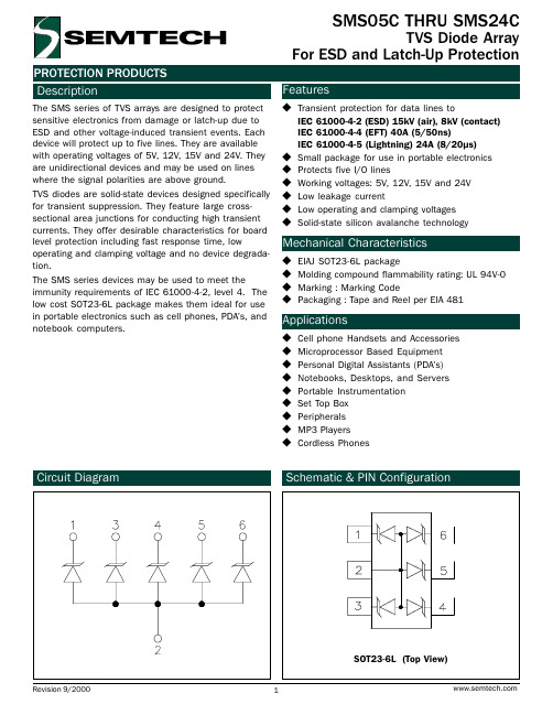
PROTECTION PRODUCTS
Description
The SMDAxxC series of TVS arrays are designed to provide bidirectional protection for sensitive electronics from damage or latch-up due to ESD, lightning and other voltage-induced transient events. Each device will protect four data or I/O lines. They are available with operating voltages of 5V, 12V, 15V and 24V.
8
15
ã 2000 Semtech Corp.
4
元器件交易网
PROTECTION PRODUCTS Applications Information
Device Connection for Protection of Four Data Lines
The SMDAxxC series devices are designed to protect up to four data lines. The devices are connected as follows:
l The SMDAxxC are bidirectional devices and are designed for use on lines where the normal operating voltage is above and below ground. Pins 1, 2, 3, and 4 are connected to the protected lines. Pins 5, 6, 7, and 8 are connected to ground. Since the device is electrically symmetrical, these connections may be reversed. The ground connections should be made directly to the ground plane for best results. The path length is kept as short as possible to reduce the effects of parasitic inductance in the board traces.
1C10C0G101J050B(vishay)中文数据手册「EasyDatasheet」

TOLERANCE
± 5% ± 10% ± 20%
AVAILABLE IN EIA CHARACTERISTIC
C0G X7R Z5U
B = Bulk
R = Tape and Reel
* 1.0 [25.4] minimum lead length.
文件编号:42012 修订25九月00
31
050 DC VOLTAGE RATING
Thisisexpressed in volts. To complete the three-digit block, zeros precede the voltage rating.
B LEAD LENGTH*
See Dimensional Configurations.
文件编号:42012 修订25九月00
芯片中文手册,看全文,戳
标准零件编号
1C20C0G222J050R 1C20C0G222J100B 1C20C0G222J100R 1C20C0G330J050B 1C20C0G330J050R 1C20C0G330J100B 1C20C0G330J100R 1C20C0G331J050B 1C20C0G331J050R 1C20C0G331J100B 1C20C0G331J100R 1C20C0G332J050B 1C20C0G332J050R 1C20C0G332J100B 1C20C0G332J100R
1C20X7R333K100B 1C20X7R333K100R 1C20X7R472K050B 1C20X7R472K050R 1C20X7R472K100B 1C20X7R472K100R 1C20X7R473K050B 1C20X7R473K050R 1C20X7R473K100B 1C20X7R473K100R 1C20Z5U103M050B 1C20Z5U103M050R 1C20Z5U103M100B 1C20Z5U103M100R 1C20Z5U104M050B 1C20Z5U104M050R 1C20Z5U104M100B 1C20Z5U104M100R 1C20Z5U223M050B 1C20Z5U223M050R
VI20200C资料

V20200C, VF20200C, VB20200C & VI20200CVishay General SemiconductorDocument Number: 89072For technical questions within your region, please contact one of the following:Dual High-Voltage Trench MOS Barrier Schottky RectifierUltra Low V F = 0.60 V at I F = 5 AFEATURES •Trench MOS Schottky technology •Low forward voltage drop, low power losses •High efficiency operation •Low thermal resistance•Meets MSL level 1, per J-STD-020, LF maximum peak of 245 °C (for TO-263AB package) •Solder dip 260 °C, 40 s (for TO-220AB, ITO-220AB and TO-262AA package) •Component in accordance to RoHS 2002/95/EC and WEEE 2002/96/EC TYPICAL APPLICATIONSFor use in high frequency inverters, switching power supplies, freewheeling diodes, OR-ing diode, dc-to-dc converters and reverse battery protection.MECHANICAL DATACase: TO-220AB, ITO-220AB, TO-263AB and TO-262AAEpoxy meets UL 94V-0 flammability ratingTerminals: Matte tin plated leads, solderable per J-STD-002 and JESD22-B102E3 suffix for commercial grade, meets JESD 201 class 1A whisker test Polarity: As markedMounting Torque:10 in-lbs maximumPRIMARY CHARACTERISTICSI F(AV) 2 x 10 A V RRM 200 V I FSM 120 A V F at I F = 10 A 0.68 V T J max.150 °C12312KMAXIMUM RATINGS (T A = 25°C unless otherwise noted)PARAME ER SYMBOL V20200C VF20200C VB20200C VI20200C UNIMaximum repetitive peak reverse voltage V RRM 200V Maximum average forward rectified current (Fig. 1)per device per diodeI F(AV)2010APeak forward surge current 8.3 ms single half sine-wave superimposed on rated load per diodeI FSM 120 A Peak repetitive reverse current at t p = 2 µs, 1 kHz per diode I RRM 0.5A Isolation voltage (ITO-220AB only)from terminal to heatsink t = 1 minV AC 1500V Operating junction and storage temperature rangeT J , T STG- 40 to + 150°CV20200C, VF20200C, VB20200C & VI20200CVishay General Semiconductor For technical questions within your region, please contact one of the following:Document Number: 89072Notes:(1) Pulse test: 300 µs pulse width, 1 % duty cycle (2) Pulse test: Pulse width ≤ 40 msRATINGS AND CHARACTERISTICS CURVES(T A = 25 °C unless otherwise noted)ELECTRICAL CHARACTERISTICS (T A = 25°C unless otherwise noted)PARAME ER T ES T CONDI T IONS SYMBOL TYP.MAX.UNI TBreakdown voltageI R = 1.0 mA T A = 25 °C V BR200 (minimum)-VInstantaneous forward voltage per diode (1)I F = 5 AI F = 10 A T A = 25 °CV F0.851.21-1.60VI F = 5 A I F = 10 A T A = 125 °C 0.600.68-0.76Reverse current per diode (2)V R = 180 V T A = 25 °C T A = 125 °CI R63.6--µA mA V R = 200 VT A = 25 °C T A = 125 °C-5.615018µA mATHERMAL CHARACTERISTICS (T A = 25°C unless otherwise noted)PARAME ER SYMBOL V20200C VF20200CVB20200C VI20200C UNI TTypical thermal resistance per diodeR θJC2.85.02.82.8°C/WORDERING INFORMATION (Example)PACKAGE PREFERRED P/N UNIT WEIGHT (g)PACKAGE CODEBASE QUANTITYDELIVERY MODETO-220AB V20200C-E3/4W 1.884W 50/tube T ube ITO-220AB VF20200C-E3/4W1.754W50/tubeT ubeTO-263AB VB20200C-E3/4W 1.374W50/tube T ubeTO-263AB VB20200C-E3/8W 1.378W800/reel T ape and reel TO-262AAVI20200C-E3/4W1.454W50/tubeT ubeFigure 1. Maximum Forward Current Derating Curve Figure 2. Forward Power Loss Characteristics Per DiodeV20200C, VF20200C, VB20200C & VI20200CVishay General SemiconductorDocument Number: 89072For technical questions within your region, please contact one of the following:Figure 3. Typical Instantaneous Forward Characteristics Per Diode Figure 4. Typical Reverse Characteristics Per Diode Figure 5. Typical Junction Capacitance Per DiodeFigure 6. Typical Transient Thermal Impedance Per DiodeFigure 7. Typical Transient Thermal Impedance Per DiodeV20200C, VF20200C, VB20200C & VI20200CVishay General Semiconductor For technical questions within your region, please contact one of the following:Document Number: 89072PACKAGE OUTLINE DIMENSIONS in inches (millimeters)Disclaimer Legal Disclaimer NoticeVishayAll product specifications and data are subject to change without notice.Vishay Intertechnology, Inc., its affiliates, agents, and employees, and all persons acting on its or their behalf (collectively, “Vishay”), disclaim any and all liability for any errors, inaccuracies or incompleteness contained herein or in any other disclosure relating to any product.Vishay disclaims any and all liability arising out of the use or application of any product described herein or of any information provided herein to the maximum extent permitted by law. The product specifications do not expand or otherwise modify Vishay’s terms and conditions of purchase, including but not limited to the warranty expressed therein, which apply to these products.No license, express or implied, by estoppel or otherwise, to any intellectual property rights is granted by this document or by any conduct of Vishay.The products shown herein are not designed for use in medical, life-saving, or life-sustaining applications unless otherwise expressly indicated. Customers using or selling Vishay products not expressly indicated for use in such applications do so entirely at their own risk and agree to fully indemnify Vishay for any damages arising or resulting from such use or sale. Please contact authorized Vishay personnel to obtain written terms and conditions regarding products designed for such applications.Product names and markings noted herein may be trademarks of their respective owners.元器件交易网Document Number: 。
- 1、下载文档前请自行甄别文档内容的完整性,平台不提供额外的编辑、内容补充、找答案等附加服务。
- 2、"仅部分预览"的文档,不可在线预览部分如存在完整性等问题,可反馈申请退款(可完整预览的文档不适用该条件!)。
- 3、如文档侵犯您的权益,请联系客服反馈,我们会尽快为您处理(人工客服工作时间:9:00-18:30)。
COMCHIP TECHNOLOGY 4115 CLIPPER CT. FREMONT CA 94538 TEL: (510) 657-8671 FAX: (510) 657-8921
元器件交易网
Glass Passivated Ultra Fast Recovery Rectifier
o o o
UF UF UF 20C01C-G 20C02C-G 20C03C-G 50 35 50 100 70 100 200 140 200 20.0
UF UF UNIT 20C04C-G 20C05C-G 400 280 400 600 420 600 V V V A
VRRM VRMS VDC IF(AV)
125
16
PEAK FORWARD SURGE CURRENT, AMPERES
AVERAGE FORWARD RECTIFIED CURRENT, AMPERES
Pulse Width 8.3ms Single Half-Sire-Wave (JEDEC Method)
100
10
75
8
50
6
4 60 Hz Resistive or Inductive load 0 0 50 100
元器件交易网
Glass Passivated Ultra Fast Recovery Rectifier
UF20C01C-G THRU UF20C05C-G
Voltage Range 50 to 600 V Current 20.0 Ampere Features Fast switching for high efficiency Low forward voltage drop High current capability Low reverse leakage current High surge current capability Mechanical Data Case: Molded plastic TO-220AB Epoxy: UL 94V-0 rate flame retardant Terminals: Solderable per MIL-STD-202 method 208 Polarity:Color band denotes cathode Mounting position: Any Weight: 2.24 grams TO-220AB
10 UF20C01C-G-UF20C03C-G
FIG.4 - TYPICAL REVERSE CHARACTERISTICS
1000
INSTANTANEOUS REVERSE CURRENT, MICROAMPERES
100
TJ=125 C
o
1.0
UF20C04C-G
UF20C05C-G
10
0.1
o
25
0 150 1 10 100
CASE TEMPERATURE, C
NUMBER OF CYCLES AT 60Hz
FIG.3 - TYPICAL INSTANTANEOUS FORWARD CHARACTERISTICS
IINSTANTANEOUS FORWARD CURRENT, AMPERES
RATINGS AND CHARACTERISTIC CURVES UF20C01C-G THRU UF20C05C-G
FIG.1 - FORWARD CURRENT DERATING CURVE
20
FIG.2 - MAXIMUM NON-REPETITIVE PEAK FORWARD SURGE CURRENT
1
TJ=25 C
o
0.01 0.4 0.6 0.8 1.0
TJ=25 C PULSE WIDTH=300uS 1% DUTY CYCLE 1.2 1.4 1.6 1.8
o
0.1 0 20 40 60 80 100
INSTANTANEOUS FORWARD VOLTAGE, VOLTS
PERCENT OF RATED PEAK REVERSE VOLTAGE,%
.113(2.87) .103(2.62) .185(4.70) .175(4.44) MAX.412(10.5) DIA .154(3.91) .148(3.74) .055(1.40) .045(1.14)
.06(1.52) .05(1.27)
.594(15.1) .587(14.9) PIN 1 2 3 .27(6.86) .23(5.84) .56(14.22) .53(13.46)
FIG.5 - TYPICAL JUNCTION CAPACITANCE
1000
JUNCTION CAPACITANCE, pF
TJ = 25 C f = 1.0 MHZ Vsig = 50mVp-p
o
100
10 0.1 1.0 4.0 10 100
REVERSE VOLTAGE, VOLTS
COMCHIP TECHNOLOGY 4115 CLIPPER CT. FREMONT CA 94538 TEL: (510) 657-8671 FAX: (510) 657-8921
SYMBOL Maximum Recurrent Peak Reverse Voltage Maximum RMS Voltage Maximum DC Blocking Voltage Maximum Average Forward Rectified Current TC=125 C Peak Forward Surge Current, 8.3ms single Half sine-wave superimposed on rated load (JEDEC method) Maximum Instantaneous Forward Voltage @ 10.0 A Maximum DC Reverse Current @TJ=25 C At Rated DC Blocking Voltage @TJ=125 C Maximum Reverse Recovery Time (Note 1) Typical junction Capacitance (Note 2) Typical Thermal Resistance (Note 3) Operating Junction and Storage Temperature Range
MAXIMUM RATINGS AND ELECTRICAL CHARACTERISTICS
Rating at 25oC ambient temperature unless otherwise specified. Single phase, half wave, 60Hz, resistive or inductive load. For capacitive load, derate current by 20%.
.16(4.06) .14(3.56)
.11(2.79) .10(2.54)
.037(0.94) .027(0.68) 1 3 case 2 .105(2.67) .095(2.41) .025(0.64) .014(0.35)
Dimensions in inches and (millimeters)
IFSM
125
A
VF
1.0 10.0 250 50 120 2.0 -55 to &#A uA
IR Trr CJ R JA TJ, TSTG
75 70
o
nS pF CW
o
C
NOTES : (1) Reverse recovery test conditions IF = 0.5A, IR = 1.0A, Irr = 0.25A. (2) Measured at 1.0 MHz and applied reverse voltage of 4.0 Volts DC. (3) Thermal Resistance junction to case.