735D476X0125C2中文资料
4763型电气阀门定位器
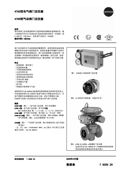
4763型和4765型的认证
AIR LIQUIDE
2003/OL 216 A
2003-07-30 带 6109 型电气转换器使用氧气气源,允许最高环境温度 60℃
EEx d隔爆型6116型电气转换器的认证请见数据表 T 6116 ZH
电气连接和尺寸(mm)
输入控制信号 4(0)至20mA
输入
输出 (38) 气源 (9)
0.19 m3(N)/h 0.5 m3(N)/h
0.13 m3(N)/h 0.33 m3(N)/h
3 m3(N)/h 8.5 m3(N)/h
240cm2:≤1.8秒 ·350cm2:≤2.5秒 ·700cm2:≤10秒·
带电气转换器
6109型 -20...70℃; 带金属电缆接头:
6112型 -20...80℃; 带金属电缆接头
气动连接 ISO 228/1 G ¼ ¼ NPT
温度范围 标准
低温到 -50℃ 特殊型
无 用于氧气气源
订货文件 电气阀门定位器 型号4763-x... 气动阀门定位器 型号4765-01...
附加规格 - 不带/带压力表 - 装配不锈钢外壳、镀铬接头的压力表或全不锈钢压力表 - 已调输入控制信号....或气源压力....巴 - 管路:镀锌管或不锈钢管或DN6/10 聚乙烯(PE)管 - 按照IEC 60534-6-1(NAMUR)标准装配
-35...80℃; 特殊型:-50...80℃
-35...70℃
-35...80℃;
特殊型:
-45...80℃
使用氧气气源型最大到60℃
温度 < 0.03%/℃·气源 < 0.3%/0.1巴
在10...150Hz和1.5g时< 2%
ST735SCD,ST735SCD, 规格书,Datasheet 资料
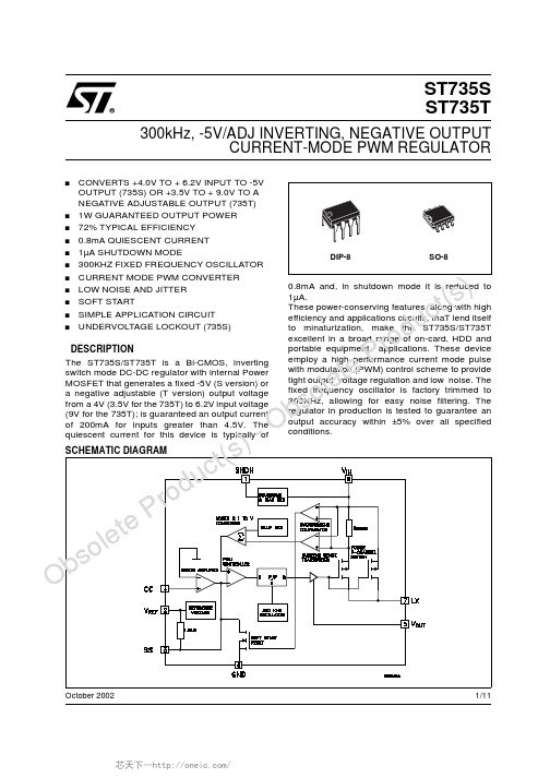
1/11October 2002sCONVERTS +4.0V TO +6.2V INPUT TO -5V OUTPUT (735S)OR +3.5V TO +9.0V TO A NEGATIVE ADJUSTABLE OUTPUT (735T)s 1W GUARANTEED OUTPUT POWER s 72%TYPICAL EFFICIENCY s 0.8mA QUIESCENT CURRENT s 1µA SHUTDOWN MODEs 300KHZ FIXED FREQUENCY OSCILLATOR s CURRENT MODE PWM CONVERTER s LOW NOISE AND JITTER s SOFT STARTs SIMPLE APPLICATION CIRCUIT sUNDERVOLTAGE LOCKOUT (735S)DESCRIPTIONThe ST735S/ST735T is a Bi-CMOS,inverting switch mode DC-DC regulator with internal Power MOSFET that generates a fixed -5V (S version)or a negative adjustable (T version)output voltage from a 4V (3.5V for the 735T)to 6.2V input voltage (9V for the 735T);is guaranteed an output current of 200mA for inputs greater than 4.5V.The quiescent current for this device is typically of 0.8mA and,in shutdown mode it is reduced to1µA.These power-conserving features,along with high efficiency and applications circuits,thaT lend itself to minaturization,make the ST735S/ST735T excellent in a broad range of on-card,HDD and portable equipment applications.These device employ a high performance current mode pulse with modulation (PWM)control scheme to provide tight output voltage regulation and low noise.The fixed frequency oscillator is factory trimmed to 300KHz,allowing for easy noise filtering.The regulator in production is tested to guarantee an output accuracy within ±5%over all specified conditions.ST735S ST735T300kHz,-5V/ADJ INVERTING,NEGATIVE OUTPUTCURRENT-MODE PWMREGULATORl c -O bs o e t eP r od u t (sl c )Ob so e t et eP r od u t (sST735S/ST735T2/11ABSOLUTE MAXIMUM RATINGSAbsolute Maximum Ratings are those values beyond which damage to the device may occur.Functional operation under these condition is not implied.Note 1:The input to output differential voltage is limited to V IN +|V OUT |<12.7VTHERMAL DATACONNECTION DIAGRAM (top view)PIN DESCRIPTIONSymbol ParameterValue Unit V IN DC Input Voltage (V IN to GND)for ST735S -0.3to +7V V IN DC Input Voltage (V IN to GND)for ST735T (Note 1)-0.3to +11V SHDN Shutdown Voltage (SHDN to GND)-0.3to V IN +0.3V V LX Switch Voltage (Lx to V IN )-12.5to +0.3V V FB Feedback Voltage (V OUT to GND)-11to +0.3V V OUT Output Voltage (V OUT to GND)-11to +0.3V Other Input Voltage (SS,CC to GND)-0.3to V ++0.3V I LX Peack Switch Current 2A P tot Power Dissipation at T j =70°C DIP-8725mW SO-8470T stg Storage Temperature Range-55to +150°CT opOperating Junction Temperature Range-40to +125°CSymbol ParameterDIP-8SO-8Unit R thj-caseThermal Resistance Junction-case28°C/WPin N°Symbol Name and Function1SHDN SHUT-DOWN Control (V CC =ON GND=Shutdown2V REF Reference Output Voltage 3SSSoft Start4CC Compensation Input 5V OUT Negative Output Voltage6GND Ground7LX Switch Output8V INPositive Supply -Voltage Inputl s Ob so e t ePr od u c t () -O bST735S/ST735T3/11ORDERING CODESTYPICAL APPLICATION CIRCUITNOTE:1)All capacitors are X7R ceramic2)C 5can be omitted if are used higher values for the input and output capacitors (suggested C 2=47µF,C 1=100µF).3)R 1and R 2must be placed is ST735T applications only.Their values are calculated by the following formula R 2=(|V OUT |/V REF )xR 1.For R 1can be chosen any value between 2k Ωand 20k ΩAPPLICATION CIRCUITTo achieve the best performances from switching power supply topology,particular care to layout drawing is needed,in order to minimize EMI and obtain low noise.Moreover,jitter free operation ensures the full device yout design proposed on demoboard helps to lower the developing time.Wire lengths must be minimized,filter and bypass capacitors must be low ESRtype,placed as close as possible to the integrated circuit.The 4.7µF (or 6.8µF)inductor must be chosen built on a core,taking care that saturation current should be higher than the peak LX switch current.See the Peak Inductor Current vs Output Current graph.PRINTED DEMOBOARD (not in scale)TYPE DIP-8SO-8SO-8(T&R)ST735S ST735SCN ST735SCD ST735SCD-TR ST735TST735TCNST735TCDST735TCD-TRl t l u )Ob so e t ePr od u c (s )- O bs o e t eP r od c t(sST735S/ST735T4/11ELECTRICAL CHARACTERISTICS OF ST735S (Refer to test circuit,V IN =5V,C IN =4.7µF,C OUT =10µF all X7R ceramic,L =4.7µH (Note1),I OUT =0mA,T amb =-40to 125°C,unless otherwise specified.Typical value are referred at T amb =25°C)Note 1:Utilize of 6.8µH permits to reach higher current capability at the same operating conditions Note2:Guaranteed by design,but not tested in production Note3:Tested at I VREF =125µASymbol ParameterTest ConditionsMin.Typ.Max.Unit V IN Input Voltage 4 6.2V V OUTOutput VoltageV IN =4.5V to 6.2V I OUT =0to 200mA T amb =-40to 125°C-5.25-5-4.75V V IN =4.0V to 6.2V I OUT =0to 175mA T amb =-40to 125°C-5.25-5-4.75V I OUTOutput CurrentV IN =4.5V to 6.2V T J =0to 125°C 200275mA V IN =4.5V to 6.2V I OUT =0to 175mA T amb =-40to 125°C 175mA V IN =4.0VV OUT =-5V175mAI SUPPLY Supply Current Includes Switch Current0.8 1.6mAI STANDBY Standby CurrentV SHDN =0V 110µA I SC Short Circuit Current V IN =5V 0.9A I PEAK LX Max Peak Current (Note 2)1.5A V LO Undervoltage Lock-out 3.54V ∆V OUT Line Regulation V IN =4.0V to 6.2V 0.1%/V ∆V OUT Load Regulation I OUT =0to 200mA 0.003%/mA V REF Reference Voltage T amb =25°C (Note 3) 1.225V ∆V REF Reference Drift T amb =-40to 125°C50ppm/°C R DSON LX ON Voltage 0.5ΩI LEAK LX Leakage Current V DS =10V 1µAI SH Shutdown Pin Current 1µA V IL Shutdown Input Low Threshold0.25V V IH Shutdown Input High Threshold2Vf OSC Maximum Oscillator Frequency 300KHz νEfficencyI OUT =100mA72%R CCCompensation Pin Impedance on CC Pin7.5K Ωl t l u )Ob so e t ePr od u c (s )- O bs o e t eP r od c t(sST735S/ST735T5/11ELECTRICAL CHARACTERISTICS OF ST735T (Refer to test circuit,V IN =5V,C IN =4.7µF,C OUT =10µF all X7R ceramic,L =4.7µH (Note1),I OUT =0mA,V O adjusted to -5V,T amb =-40to 125°C,unless otherwise specified.Typical value are referred at Tamb=25°C)Note 1:Utilize of 6.8µH permits to reach higher current capability at the same operating conditions Note2:Guaranteed by design,but not tested in production Note3:Tested at I VREF =125µASymbol ParameterTest ConditionsMin.Typ.Max.Unit V IN Input Voltage 3.59V V OOutput VoltageV IN =4.5V to 6.2V I OUT =0to 200mA T amb =-40to 125°C-5.25-5-4.75V V IN =4.0V to 6.2V I OUT =0to 175mA T amb =-40to 125°C-5.25-5-4.75V I OOutput CurrentV IN =4.5V to 6.2V T amb =0to 125°C 200275mA V IN =4.5V to 6.2V I OUT =0to 175mA T amb =-40to 125°C 175mA V IN =4.0VV OUT =-5V175mAI SUPPLY Supply Current Includes Switch Current0.8 1.6mAI STANDBY Standby CurrentV SHDN =0V 110µA I SC Short Circuit Current V IN =5V 0.9A I PEAK LX Max Peak Current (Note 2)1.5A V LO Undervoltage Lock-out 3.54V ∆V OUT Line Regulation V IN =4.0V to 6.2V 0.1%/V ∆V OUT Load Regulation I OUT =0to 200mA 0.003%/mA V REF Reference Voltage T amb =25°C (Note 3) 1.225V ∆V REF Reference Drift T amb =-40to 125°C50ppm/°C R DSON LX ON Voltage 0.5ΩI LEAK LX Leakage Current V DS =10V 1µAI SH Shutdown Pin Current 1µA V IL Shutdown Input Low Threshold0.25V V IH Shutdown Input High Threshold2Vf OSC Maximum Oscillator Frequency 300KHz νEfficencyI OUT =100mA72%R CCCompensation Pin Impedance on CC Pin7.5K ΩO-O ST735S/ST735T6/11TYPICAL CHARACTERISTICS (Referred to typical application circuit,T amb =25°C unless otherwise specified)Figure 1:Output Voltage vs TemperatureFigure 2:Reference Voltage vs Temperature Figure 3:Efficency vs TemperatureFigure 4:Efficency vs Ouput CurrentFigure 5:Efficency vs Low Ouput CurrentFigure 6:Supply Current vs TemperatureOo-OsST735S/ST735T7/11Figure7:Supply Current vs Input Voltage for ST735SFigure8:Supply Current vs Input Voltage for ST734TFigure9:Shutdown Threshold vs Temperature Figure10:Peack Inductor vs Output Current Figure11:Switch Current Limit vs Soft Start VoltageFigure12:Oscillator Frequency Vs Temperaturel l c )Ob so e t ePr o-O bs o e t eP r od u t (sST735S/ST735T8/11Figure 13:LX On Resistance vs TemperatureFigure 14:LX On Resistance vs Input Voltage Figure 15:Load TransientFigure 16:Load TransientFigure 17:Load TransientFigure 18:Switching WaveformV I =5V,I O =20mA to 200mA,C I =4.7µF,C O =100µF,t r =t f =1µs V I =5V,I O =20mA to 200mA,C I =4.7µF,C O =100µF,t f =1µsV I =5V,I O =20mA to 200mA,C I =4.7µF,C O =100µF,t r =1µsV I =5V,I O =100mAl slc)O b s oe t eP ro du ct()-O bs oe t eP ro dut(sST735S/ST735T11/11Information furnished is believed to be accurate and reliable. However, STMicroelectronics assumes no responsibility for the consequences of use of such information nor for any infringement of patents or other rights of third parties which may result from its use. No license is granted by implication or otherwise under any patent or patent rights of STMicroelectronics. Specifications mentioned in this publication are subject to change without notice. This publication supersedes and replaces all information previously supplied. STMicroelectronics products are not authorized for use as critical components in life support devices or systems without express written approval of STMicroelectronics.© The ST logo is a registered trademark of STMicroelectronics© 2002 STMicroelectronics - Printed in Italy - All Rights ReservedSTMicroelectronics GROUP OF COMPANIESAustralia - Brazil - Canada - China - Finland - France - Germany - Hong Kong - India - Israel - Italy - Japan - Malaysia - Malta - Morocco Singapore - Spain - Sweden - Switzerland - United Kingdom - United States.© 芯天下--/。
德力西 CDBXZ直流小型断路器 产品说明书

目 录CONTENT12 11注:只有符合RoHS的物料才符合CE认证。
14 13注:只有符合RoHS的物料才符合CE认证。
1615备注:1.仅CDBX 产品编码中极数编码5代表1P+N 产品;2.CDBXP 产品全部为1P+N 产品,产品编码中极数代码缺省;■ 产品说明短路保护、过载保护、隔离功能■主要功能额定工作电压(V )1P :230/400 、240/415AC 1P+N :230/240 AC 2P,3P,3P+N,4P :400/415 AC 额定电流(A )1,2,3,4,5,6,8,10,13,16,20,25,32,40,50,63额定频率(Hz )50/60极数1P,1P+N,2P,3P,3P+N,4P 分断能力(kA )6、10脱扣曲线B 、C 、D 型■ 主要特性GB/T 10963.1 ■ 符合标准■ 符合认证注:该产品可拼装附件OF,SD,MSN,MV,MN,MVMN,FF,FS,MO(有源型),MOWY(无源型)■ 电气特性额定绝缘电压 Ui (V )500额定工作电压Ue (V ) 1P (V )230/400 AC 、240/415 AC 1P+N (V )230/240 AC 2P ,3P ,4P ,3P+N (V )400/415 AC 额定短路能力 Icn (IEC/EN 60898-1) (kA )6、10额定冲击耐受电压 Uimp (1.2/50) (kV )4 介电测试电压(kV )2kV (50/60Hz,1分钟)隔离功能具备污染等级2脱扣形式热磁脱扣热磁脱扣特性B 型曲线(3ln~5ln )■C 型曲线(5ln~10ln )■D 型曲线(10ln~14ln )■电气及机械附件■1817手柄红色,移印指示ON-OFF 位置机械寿命次20000电气寿命次12000防护等级安装于配电箱内:IP40直接安装:IP20抗机械冲击30g,3次冲击,持续时间11ms (无显著振动和冲击的地方)抗震动(IEC/EN 60068-2-6)无显著振动和冲击的地方抗湿热性(IEC 60068-2)湿热 ℃/RH 2类,28次循环,温度55℃时,相对湿度90%~96%温度25℃时,相对湿度95~100%基准环境温度 ℃30℃使用环境温度(日平均温度≤+35℃) ℃ -35℃~+70℃存储温度 ℃-40℃~+85℃■ 机械特性接线端子形式U 接线端子最大接线能力电流等级1-63A :25mm 2最大极限扭矩电流等级1-63A :2.5N.m 工具十字螺丝刀或者一字螺丝刀安装安装于标准DIN 导轨(35mm )进线方式上下均可进线■ 安装特性■ 尺寸图■接线图1P3P4P2P1P+N3P+N 短路保护、过载保护、隔离功能■ 主要功能额定工作电压(V )1P :230/400 AC 1P+N :230 AC 2P,3P,3P+N,4P :400 AC 1P :60V DC 2P :125V DC 额定电流(A )1-63额定频率(Hz )50(仅限交流)极数1P,1P+N,2P,3P,3P+N,4P 分断能力(kA )6■ 主要特性GB/T14048.2■ 符合标准■ 符合认证注:该产品可拼装附件OF,SD,MSN,MV,MN,MVMN,FF,FS,MO (有源型),MOWY(无源型)■ 电气特性额定绝缘电压 Ui (V )500最大工作电压 Ubmax 1P ,1P+N (V )230/400 AC 2P ,3P ,3P+N ,4P (V )400 AC 1P (V )60DC 2P (V )125DC 额定短路能力 Icn (IEC/EN60898) (kA )6额定冲击耐受电压 Uimp (1.2/50) (kV )4 介电测试电压(kV )2kV (50/60Hz,1分钟)使用类别A 隔离功能具备污染等级2脱扣形式热磁脱扣热磁脱扣特性Ii (B)型曲线4ln(AC)、5In(DC)■Ii (C)型曲线8ln(AC)、10In(DC)■Ii (D)型曲线12ln(AC)、15In(DC)■电气及机械附件■20191P 1P+N 3P 4P 2P3P+N1P 左视图1P 3P 1P+N ,2P 3P+N ,4P■ 尺寸图■ 接线图手柄红色,移印指示ON-OFF 位置机械寿命次20000电气寿命次10000防护等级安装于配电箱内:IP40直接安装:IP20抗机械冲击30g,3次冲击,持续时间11ms (无显著振动和冲击的地方)抗震动(IEC/EN 60068-2-6)无显著振动和冲击的地方抗湿热性(IEC 60068-2)湿热 ℃/RH 2类,28次循环,温度55℃时,相对湿度90%~96%温度25℃时,相对湿度95~100%基准环境温度 ℃30℃使用环境温度(日平均温度≤+35℃) ℃ -35℃~+70℃存储温度℃-40℃~+85℃■ 机械特性接线端子形式U 接线端子最大接线能力电流等级1-63:25mm 2最大极限扭矩电流等级1-63:2.5N.m 工具十字螺丝刀或者一字螺丝刀安装安装于标准DIN 导轨(35mm )进线方式上下均可进线■ 安装特性短路保护、过载保护、漏电保护、隔离功能、过压保护(仅限于过压型号产品)■ 主要功能GB/T 16917.1 ■ 符合标准■符合认证额定工作电压(V )1P+N,2P :230 AC 3P,3P+N,4P :400 AC 额定电流(A )一般型:6~63S 型(延时型):32~63额定频率(Hz )50/60极数1P+N,2P,3P,3P+N,4P 分断能力(kA )6、10脱扣曲线B 、C 、D 型额定剩余动作电流(mA)一般型:10(1P+N 、2P),30,50,75,100,300S 型(延时型):50,75,100,300漏电脱扣时间一般型:t ≤0.1S S 型:0.13S ≤t ≤0.5S 漏电保护类型A 、AC 型过压保护功能(V)(280±14)VAC(仅适用于1P+N,2P)■ 主要特性 小体积,省空间:宽度整模数化,体积减小30%~50%,节约柜体空间及成本 大孔接线:25mm 2大孔接线,接线更便捷 规格齐全:增加A 型漏电保护、10kA 分断能力、漏电延时型及下进线规格,保护更全面,布线更灵活 快速闭合+放喷弧挡板设计:使用寿命更长久,分合闸操作更放心注:该产品可拼装附件:OF ,SD ,MSN ,MV ,MN ,MVMN ,FF ,FS ,MO (有源型),MOWY (无源型)22 21额定绝缘电压 Ui(V)500最大工作电压 Uemax (V)1P+N,2P:230 AC3P,3P+N,4P:400 AC额定短路能力 Icn(kA)6、10额定冲击耐受电压 Uimp(1.2/50)(kV) 4介电测试电压2kV(50/60HZ,1分钟)隔离功能具备(1P+N、3P+N不具备)漏电保护类型A、AC型污染等级2脱扣形式热磁脱扣热磁脱扣特性B型曲线(3ln~5ln)■C型曲线(5ln~10ln)■D型曲线(10ln~14ln)■电气及机械附件■■ 电气特性脱扣指示CDBXLES上有剩余电流动作脱扣指示,复位按钮弹起,为漏电脱扣手柄红色,机械寿命次20000电气寿命次10000防护等级安装于配电箱内IP40直接安装IP20抗机械冲击30g,3次冲击,持续时间11ms(无显著振动和冲击的地方)抗震动 (IEC/EN 60068-2-6)无显著振动和冲击的地方抗湿热性(IEC 60068-2)湿热℃/RH2类,28次循环,温度55℃时,相对湿度90%~96%温度25℃时,相对湿度95%~100%基准环境温度℃30℃使用环境温度(日平均温度≤+35℃) ℃-35℃~+70℃存储温度℃ -40℃~+85℃■ 机械特性接线端子形式U接线端子最大接线能力25mm2最大极限扭矩 2.5 N.m工具十字螺丝刀或者一字螺丝刀安装安装于标准DIN导轨(35mm)进线方式上进线(所有极数);下进线(仅有1P+N/2P规格产品)■ 安装特性1P+N/2P■ 尺寸图1P+N3P+N4P2P3P■ 接线图■ 主要功能额定工作电压(V)230AC额定电流(A)6,10,16,20,25,32,40额定频率(Hz)50■ 主要特性GB/T 10963.1■ 符合标准■ 符合认证短路保护、过载保护、隔离功能极数1P+N分断能力(kA) 4.5、6注:该产品可拼装附件:OF,SD,MSN,MV,MN,MVMN,FF,FS,MO(有源型),MOWY(无源型)2423额定绝缘电压 Ui (V )500额定电压Ue (V )(V )230额定短路能力 Icn (IEC/EN60898-1)(kA ) 4.5、6额定冲击耐受电压 Uimp (1.2/50)(kV ) 4介电测试电压2kV (50HZ,1分钟)隔离功能具备污染等级2脱扣形式热磁脱扣热磁脱扣特性C 型曲线(5ln~10ln)■D 型曲线(10ln~14ln)■电气及机械附件■■ 电气特性手柄红色,移印指示ON-OFF 位置机械寿命次20000电气寿命次10000防护等级安装于配电箱内:IP40直接安装:IP20抗机械冲击30g,3次冲击,持续时间11ms (无显著振动和冲击的地方)抗震动(IEC/EN 60068-2-6)无显著振动和冲击的地方抗湿热性(IEC 60068-2)湿热℃/RH2类,28次循环,温度55℃时,相对湿度90%~96%温度25℃时,相对湿度95~100%基准环境温度℃30℃使用环境温度(日平均温度≤+35℃) ℃ -35℃~+70℃存储温度℃-40℃~+85℃■ 机械特性接线端子形式U 接线端子最大接线能力电流等级6-40:10mm 2最大极限扭矩电流等级6-40:2 N.m工具十字螺丝刀或者一字螺丝刀安装安装于标准DIN 导轨(35mm )进线方式上下均可进线■ 安装特性1P+N■ 接线图■ 主要功能额定工作电压(V )1P ,1P+N :230/240AC 、80DC2P,3P,3P+N,4P :400/415 AC (2P :125 DC )额定电流(A )63-125额定频率(Hz )50/60极数1P ,1P+N,2P ,3P ,3P+N,4P 分断能力(kA )10■ 主要特性GB/T 14048.2■ 符合标准短路保护、过载保护、隔离功能■符合认证注:该产品可拼装附件 OF ,SD ,MO ,MV ,MN ,MVMN2625额定绝缘电压 Ui(V )500额定工作电压Ue(V )1P ,1P+N :230/240 AC 、80 DC2P ,3P ,3P+N ,4P :400/415 AC (2P :125 DC )额定短路能力Icn (IEC/EN60898-1)(kA )10额定冲击耐受电压 Uimp (1.2/50)(kV )4 介电测试电压2kV(50HZ,1分钟)隔离功能具备污染等级2脱扣形式热磁脱扣热磁脱扣特性C 型曲线(5ln~10ln)■D 型曲线(10ln~14ln)■电气及机械附件■■ 电气特性接线端子形式U 接线端子最大接线能力电流等级63-125:50mm 2最大极限扭矩电流等级63-125:3.5N.m工具十字螺丝刀或者一字螺丝刀安装安装于标准DIN 导轨(35mm )进线方式上下均可进线■ 安装特性■ 机械特性手柄红色触头指示通过红绿色指示产品的通断机械寿命次20000电气寿命次6000次(In ≤100A )4000次(In>100A )防护等级安装于配电箱内IP40直接安装IP20抗机械冲击30g,3次冲击,持续时间11ms (无显著振动和冲击的地方)抗震动 (IEC/EN 60068-2-6)无显著振动和冲击的地方抗湿热性(IEC 60068-2)湿热 ℃/RH2类,28次循环,温度55℃时,相对湿度90%~96%温度25℃时,相对湿度95%~100%基准环境温度℃30℃使用环境温度(日平均温度≤+35℃) ℃-35℃~+70℃存储温度℃ -40℃~+85℃■ 接线图1P3P4P2P1P+N3P+N2827■ 主要功能额定工作电压(V )1P+N,2P :230/240AC3P,3P+N,4P :400/415AC额定电流(A )63-125额定频率(Hz )50/60极数1P+N,2P ,3P ,3P+N,4P■ 主要特性GB/T 14048.2■ 符合标准■ 符合认证短路保护、过载保护、漏电保护、隔离功能、过压保护分断能力(kA )10额定剩余动作电流(mA )30,50,75,100,300漏电动作时间t ≤0.1s过压保护功能(V )(280±14)AC(仅适用于1P+N 、2P D 型产品,I △n=30mA)注: 该产品可拼装附件 OF ,SD额定绝缘电压 Ui(V )500额定工作电压Ue(V )1P+N,2P :230/240 AC 3P ,3P+N,4P :400/415 AC额定短路能力Icu (IEC/EN60898)(kA )10额定冲击耐受电压 Uimp (1.2/50)(kV )4 介电测试电压2kV (50HZ,1分钟)隔离功能具备漏电保护类型A 、AC 型污染等级2脱扣形式热磁脱扣热磁脱扣特性C 型曲线(5ln~10ln)■D 型曲线(10ln~14ln)■电气及机械附件■■ 电气特性接线端子形式U 接线端子最大接线能力电流等级63-125:50mm 2最大极限扭矩电流等级63-125:3.5N.m工具十字螺丝刀或者一字螺丝刀安装安装于标准DIN 导轨(35mm )进线方式上进线■ 安装特性■ 机械特性脱扣指示CDBXLE-125上有剩余电流动作脱扣指示,复位按钮弹起,为漏电脱扣手动控制过电流故障给断路器手柄合闸漏电故障剩余电流动作装置先复位,断路器后复位手柄红色,移印指示ON-OFF 位置机械寿命次20000电气寿命次6000次(In ≤100A )4000次(In>100A )防护等级安装于配电箱内IP40直接安装IP20抗机械冲击30g,3次冲击,持续时间11ms (无显著振动和冲击的地方)抗震动 (IEC/EN 60068-2-6)无显著振动和冲击的地方抗湿热性(IEC 60068-2)湿热 ℃/RH2类,28次循环,温度55℃时,相对湿度90%~96%温度25℃时,相对湿度95%~100%基准环境温度℃30℃使用环境温度(日平均温度≤+35℃) ℃-35℃~+70℃存储温度℃ -40℃~+85℃1P+N 2P1P+N右视图30293P3PN■ 接线图4P3P+N1P+N3P2P■ 主要功能额定电压(V )1P DC250V ;2P/3P DC500V额定电流(A )1,2,3,4,5,6,8,10,13,16,20,25,32,40,50,63A (B 型无1-6A )极数1P/2P/3P 分断能力(kA )6■ 主要特性短路保护、过载保护、隔离、控制GB/T 14048.2■ 符合标准■ 符合认证注:该产品可拼装附件OF,SD,MSN,MV,MN,MVMN,FF,FS,MO (有源型),MOWY(无源型)■ 机械特性机械寿命次20000电气寿命次10000环境使用温度℃-35℃~70℃3231■33机械寿命次10000电气寿命次3000防护等级安装于配电箱内IP40直接安装IP20抗机械冲击30g,3次冲击,持续时间11ms (无显著振动和冲击的地方)抗震动 (IEC/EN 60068-2-6)无显著振动和冲击的地方抗湿热性(IEC 60068-2)湿热℃/RH2类,28次循环,温度55℃时,相对湿度90%~96%温度25℃时,相对湿度95%~100%基准环境温度℃30℃使用环境温度(日平均温度≤+35℃) ℃-35℃~+70℃存储温度℃ -40℃~+85℃■ 机械特性接线端子形式隧道式接线端子最大接线能力 3.5N.m 最大极限扭矩50mm 2工具十字螺丝刀或者一字螺丝刀安装安装于标准DIN 导轨(35mm )进线方式上下进线均可■ 安装特性1P2P1P2P4P35■ 主要功能主要包含如 MO (分励脱扣)、OF (辅助触头)、SD (报警触头)、MSN(失压保护)等多类型附件GB/T 14048.1GB/T 14048.5■ 符合标准■ 符合认证品类齐全可靠稳定。
AMP04FSZ,AMP04FPZ,AMP04EPZ,AMP04FSZ-RL,AMP04FSZ-R7,AMP04FS-REEL7,AMP04ESZ-R7, 规格书,Datasheet 资料
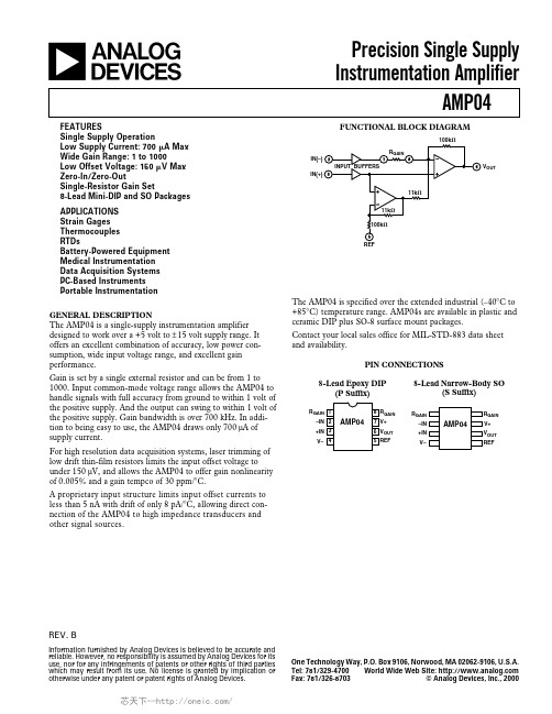
One Technology Way, P.O. Box 9106, Norwood, MA 02062-9106, U.S.A.
Tel: 781/329-4700 World Wide Web Site:
Fax: 781/326-8703
© Analog Devices, Inc., 2000
For high resolution data acquisition systems, laser trimming of low drift thin-film resistors limits the input offset voltage to under 150 µV, and allows the AMP04 to offer gain nonlinearity of 0.005% and a gain tempco of 30 ppm/°C.
1000 1 0.005 0.015 0.025 30
0.75 %
1.0 %
0.75
%
1000 V/V
%
%
%
50
ppm/°C
OUTPUT Output Voltage Swing High
Output Voltage Swing Low Output Current Limit
VOH
RL = 2 kΩ
Contact your local sales office for MIL-STD-883 data sheet and availability.
PIN CONNECTIONS
8-Lead Epoxy DIP (P Suffix)
8-Lead Narrow-Body SO (S Suffix)
25
变频器说明书大全
目录一、用户须知 2二、注意事项 3三、系统简介 4四、输出逆变系统 5五、可控整流系统 40附录一维护与保养 54附录二、依照EMC导则进行传动装置设计的说明 55一、用户须知该变频调速装置为电力电子器件组成,在运输及安装过程中,尽量避免强烈的震动,尽量垂直运输。
该变频调速装置尽量安装在干燥通风的区域,变频器的散热片距墙壁(或遮挡物)距离应大于米。
长期不用时,应存放在清洁干燥的地方;在井下安装好而不运行的状况下,该设备尽量不停电。
使用之前,必须详细阅读用户手册。
二、注意事项变频调速装置其隔爆外壳体及本安控制盒的结构和非本安及本安电路的电气参数,在出厂前均已装配调试合格,用户严禁改动变频调速装置壳体的结构和电气参数,以确保本产品的防爆性能、电气性能和本安性能。
设备在带电情况下,严禁松动隔爆壳紧固件,在检修或处理故障时,请注意“断电源后开盖”。
(注:本安接线腔不受此限制)外壳应接地良好。
电源接线隔爆腔在接线时请注意按图接线,不得接错。
装置防爆主腔内进行操作时,手上必须带接地导线或静电环。
装置电源R、S、T停电以后5分钟内禁止对变频器隔爆主腔内的任意电路进行操作,且必须用仪表确认机内电容已放电完毕,方可实施机内作业。
停电以后1分钟内禁止再次给电。
负载运行过程中尽量减少瞬时停电次数。
禁止对变频器主回路及控制回路进行耐压试验,如对与变频有电路联系的相关设备进行耐压试验之前应将与变频相关的电路切断。
测量变频器输出电压时必须使用整流式交流电压表,使用其它非整流式电压表测量高频脉冲电压时,容易产生误操作或显示不准确。
变频器安装应远离大容量变压器及电动机(容量为变频器的10倍以上)。
该系统输出端不可以加装进项电容或阻容吸收装置。
该系统变频器箱与电抗器箱连接必须完全按照相关图纸,以保证反馈电压相序一致。
未经唐山开诚电器有限责任公司许可,用户不得随意改动本系统安装调试后设置的ZJT-MSC参数及ZJT-MSC2参数(尤其是不允许通过操作防爆主腔内部的键盘更改ZJT-MSC2参数)。
常用稳压管型号之欧阳术创编
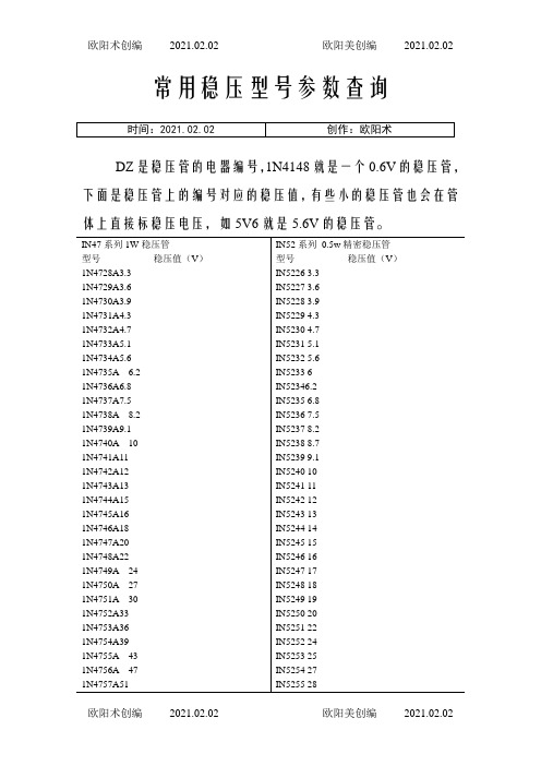
常用稳压型号参数查询DZ是稳压管的电器编号,1N4148就是一个0.6V的稳压管,下面是稳压管上的编号对应的稳压值,有些小的稳压管也会在管体上直接标稳压电压,如5V6就是5.6V的稳压管。
美标稳压二极管型号:HITACHI(日立):HITACHI(日立)0.5W稳压二极管型号参数稳压HZ3A1 2.5~2.7VHZ3A2 2.6~2.8VHZ3A3 2.6~2.9VHZ3B1 2.8~3.0VHZ3B2 2.9~3.1VHZ3B3 3.0~3.2V线性稳压器件(输入输出电流相等,压降3V以上)型号稳压(V) 最大输出电流可替代型号79L05 -5V 100mA79L06 -6V 100mA79L08 -8V 100mALM7805 5V 1A L7805,LM340T5LM7806 6V 1A L7806LM7808 8V 1A L7808LM7809 9V 1A L7809LM7812 12V 1A L7812,LM340T12LM7815 15V 1A L7815,LM340T15LM7818 18V 1A L7815LM7824 24V 1A L7824LM7905 -5V 1A L7905LM7906 -6V 1A L7906,KA7906LM7908 -8V 1A L7908LM7909 -9V 1A L7909LM7912 -12V 1A L7912LM7915 -15V 1A L7915LM7918 -18V 1A L7918LM7924 -24V 1A L792478L05 5V 100mA78L06 6V 100mA78L08 8V 100ma78L09 9V 100ma78L12 12V 100ma78L15 15V 100ma78L18 18V 100ma78L24 24V 100ma开关稳压器件(电压转换效率高)型号说明最大输出电流LM1575T-3.3 3.3V简易开关电源稳压器1ALM1575T-5.0 5V简易开关电源稳压器1ALM1575T-12 12V简易开关电源稳压器1ALM1575T-15 15V简易开关电源稳压器1ALM1575T-ADJ 简易开关电源稳压器(可调1.23V~37V) 1ALM1575HVT-3.3 3.3V简易开关电源稳压器1ALM1575HVT-5.0 5V简易开关电源稳压器1ALM1575HVT-12 12V简易开关电源稳压器1ALM1575HVT-15 15V简易开关电源稳压器1ALM1575HVT-ADJ 简易开关电源稳压器(可调1.23V~37V) 1ALM2575T-3.3 3.3V简易开关电源稳压器1ALM2575T-5.0 5V简易开关电源稳压器1ALM2575T-12 12V简易开关电源稳压器1ALM2575T-15 15V简易开关电源稳压器1ALM2575T-ADJ 简易开关电源稳压器(可调1.23V~ 37V) 1ALM2575HVT-3.3 3.3V简易开关电源稳压器1ALM2575HVT-5.0 5V简易开关电源稳压器1ALM2575HVT-12 12V简易开关电源稳压器1ALM2575HVT-15 15V简易开关电源稳压器1ALM2575HVT-ADJ 简易开关电源稳压器(可调1.23V~37V) 1ALM2576T-3.3 3.3V简易开关电源稳压器3A LM2576T-5.0 5.0V简易开关电源稳压器3A LM2576T-12 12V简易开关电源稳压器3A LM2576T-15 15V简易开关电源稳压器3A LM2576T-ADJ 简易开关电源稳压器(可调1.23V~37V) 3A LM2576HVT-3.3 3.3V简易开关电源稳压器3ALM2576HVT-5.0 5.0V简易开关电源稳压器3ALM2576HVT-12 12V简易开关电源稳压器3ALM2576HVT-15 15V简易开关电源稳压器3ALM2576HVT-ADJ 简易开关电源稳压器(可调1.23V~37V) 3A。
735D477X0025C2中文资料
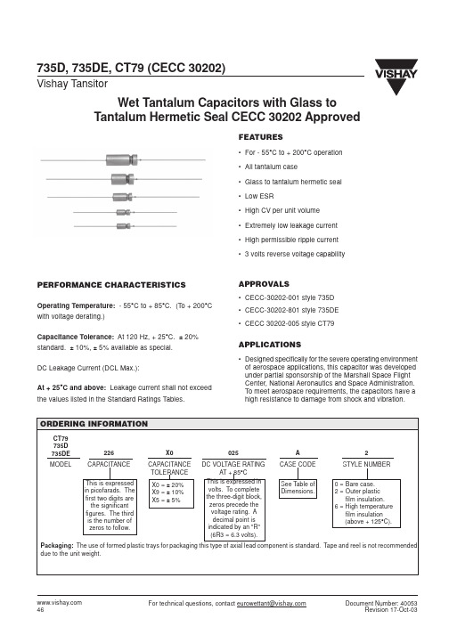
X0 CAPACITANCE TOLERANCE X0 = ± 20% X9 = ± 10% X5 = ± 5%
025 DC VOLTAGE RATING AT + 85°C This is expressed in volts. To complete the three-digit block, zeros precede the voltage rating. A decimal point is indicated by an "R" (6R3 = 6.3 volts).
Wet Tantalum Capacitors with Glass to Tantalum Hermetic Seal CECC 30202 Approved
DIMENSIONS in inches [millimeters]
E L1 E D
Vishay Tansitor
0.0253 ± 0.002 [0.64 ± 0.05] Dia. (No. 22 AWG) Tinned Nickel Leads Solderable and Weldable
WEIGHT IN GRAMS (Max.) 2.6 6.2 11.6 17.7
*For insulated parts, add 0.007" [0.178] to the diameter. The insulation shall lap over the ends of the capacitor body.
元器件交易网
735D, 735DE, CT79 (CECC 30202)
Vishay Tansitor
STANDARD RATINGS
MAX DF at + 20°C (%) 10 20 22 25 42 55 40 37 40 80 95 92 103 7 11 13 16 21 35 35 35 30 48 35 48 60 60 82 7 10 11 15 25 30 23 23 37 43 43 45 MAX DCL MAX IMP. IN µA at MAX CAP. CHANGE at - 55°C + 85°C & (%) at (Ω) + 20°C + 125°C - 55°C + 85°C + 125°C 90 100 100 50 62 60 30 24 23 42 42 25 25 140 140 130 120 50 62 60 33 27 48 24 48 48 24 26 175 200 190 60 60 62 35 27 52 52 30 30 1.0 1.5 1.5 1.0 2.0 2.0 2.0 3.0 3.0 5.0 6.0 8.0 8.0 1.0 1.5 1.5 2.0 1.0 2.0 2.0 2.0 3.0 7.0 3.0 7.0 7.0 8.0 8.0 1.0 1.5 1.5 1.0 2.0 2.0 2.0 3.0 7.0 8.0 8.0 9.0 2.0 3.0 3.0 7.0 10 12 14 18 18 20 24 32 32 2.0 3.0 3.0 9.0 9.0 10 10 13 20 28 20 28 28 32 32 2.0 4.0 4.0 8.0 10 12 12 22 28 32 32 36 -28 -28 -28 -28 -35 -45 -58 -75 -80 -80 -80 -82 -84 -20 -20 -24 -28 -28 -35 -48 -52 -60 -70 -68 -76 -80 -80 -80 -20 -20 -24 -24 -40 -32 -48 -58 -60 -65 -75 -80 +14 +16 +16 +14 +16 +18 +18 +25 +25 +25 +25 +25 +25 +10 +12 +14 +16 +13 +15 +14 +18 +25 +25 +25 +25 +25 +25 +25 +10 +12 +12 +13 +15 +15 +14 +23 +25 +25 +25 +25 +16 +16 +16 +16 +16 +18 +20 +25 +25 +25 +25 +25 +30 +12 +12 +14 +16 +15 +15 +15 +20 +25 +25 +25 +25 +25 +25 +25 +12 +12 +12 +15 +15 +15 +15 +23 +25 +25 +25 +25 MAX RMS RIPPLE CURRENT 40KHz (mA) 820 760 760 1230 1215 1215 1760 2100 2300 1585 1585 2300 2300 800 715 715 715 1215 1130 1130 1615 1865 1400 2025 1400 1400 1940 1865 660 580 580 1285 1285 1245 1525 1900 1375 1375 1900 1900 Document Number: 40053 Revision 17-Oct-03
AD7356_中文资料

VDD VDRIVE
AD7356
VINA+ VINA– REFA T/H 12-BIT SUCCESSIVE APPROXIMATION ADC
SDATAA
Information furnished by Analog Devices is believed to be accurate and reliable. However, no responsibility is assumed by Analog Devices for its use, nor for any infringements of patents or other rights of third parties that may result from its use. Speci cations subject to change without notice. No license is granted by implication or otherwise under any patent or patent rights of Analog Devices. Trademarks and registered trademarks are the property of their respective owners.
产品聚焦
1. 两个完整的 ADC,允许两个通道同步采样和转换。两 个通道的转换结果可通过独立的数据线路同时获得, 或如果仅有一个串行端口可用,则通过一条数据线路 先后获得。 2. 高吞吐速率、低功耗。AD7356提供5 MSPS吞吐速率, 功耗为36 mW。 3. 无转换延迟。AD7356采用两个标准逐次逼近型ADC, 通过CS输入和转换控制能够精确控制采样时刻。
空气开关型号说明及代表的意思含义.
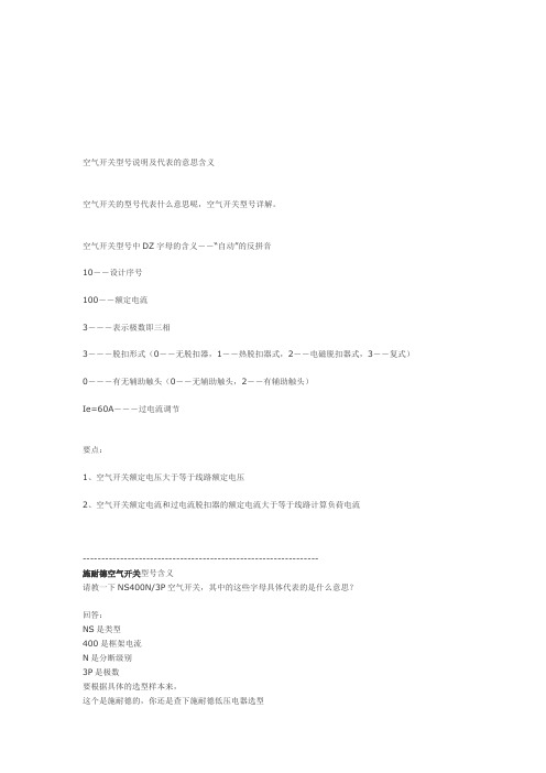
空气开关型号说明及代表的意思含义空气开关的型号代表什么意思呢,空气开关型号详解。
空气开关型号中DZ字母的含义--“自动”的反拼音10--设计序号100--额定电流3---表示极数即三相3---脱扣形式(0--无脱扣器,1--热脱扣器式,2--电磁脱扣器式,3--复式)0---有无辅助触头(0--无辅助触头,2--有辅助触头)Ie=60A---过电流调节要点:1、空气开关额定电压大于等于线路额定电压2、空气开关额定电流和过电流脱扣器的额定电流大于等于线路计算负荷电流---------------------------------------------------------------施耐德空气开关型号含义请教一下NS400N/3P空气开关,其中的这些字母具体代表的是什么意思?回答:NS是类型400是框架电流N是分断级别3P是极数要根据具体的选型样本来,这个是施耐德的,你还是查下施耐德低压电器选型这里应该有下这个型号不完整NS400N/3P XXX,最后面才是断路器的额定电流.不同的生产商所生产的产品代号是不一样的---------------------------------------------------------------三种空气开关上的标签第一种:multi9C65NC6第二种:DZ47-60C20第三种:DZ47-63C63请教各位上面三种空开的数字和字母的含义回答:施耐德包括微型断路器塑壳断路器框架断路器(智能断路器)施耐德微型断路器代号标注方法:举例:1-C65N-C20A/2P+VE+30mA+SD,各项含义为1---------识别号C65------序列代号N--------分断能力,N为6000A,H为10000A,L为15kAC--------脱扣曲线,B为电子保护,C为配电保护,D为动力保护20A------额定电流,有1、2、4、6、10、16、20、25、32、40、50、63A2P-------极数,有1、2、3、4极VE-------剩余电流附件,有VE、VEG、VM、VEA,VM为电磁式30mA-----剩余动作电流,有30、100、300mASD-------选配附件,有MX、OF、MN、MV、SD、Tm、ATm,其中SD为辅助接点。
MAX4761ETX+中文资料
MAX4760/MAX4760A/MAX4761/MAX4761A
Applications
USB Signal Switching Audio-Signal Switching Cellular Phones PDAs/Handheld Devices Notebook Computers
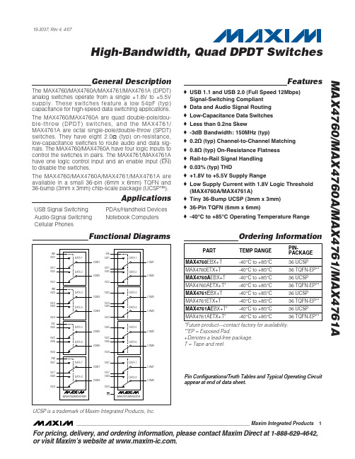
Functional Diagrams
Ordering Information
PART TEMP RANGE -40°C to +85°C -40°C to +85°C -40°C to +85°C -40°C to +85°C -40°C to +85°C -40°C to +85°C -40°C to +85°C -40°C to +85°C PINPACKAGE 36 UCSP 36 TQFN-EP** 36 UCSP 36 TQFN-EP** 36 UCSP 36 TQFN-EP** 36 UCSP 36 TQFN-EP**
INA NO1 DATA 1 COM1 NC1 NO2 DATA 2 COM2 NC2 INB NO3 NC2 NO3 COM3 NC3 NO4 DATA 4 COM4 NC4 INC NO5 NC4 NO5 COM5 NC5 NO6 DATA 6 COM6 NC6 IND NO7 NC6 NC5 NO6 DATA 6 COM6 NC3 NO4 DATA 4 COM4 NC1 NO2 DATA 2 COM2 INA NO1
Features
♦ USB 1.1 and USB 2.0 (Full Speed 12Mbps) Signal-Switching Compliant ♦ Data and Audio Signal Routing ♦ Low-Capacitance Data Switches ♦ Less than 0.2ns Skew ♦ -3dB Bandwidth: 150MHz (typ) ♦ 0.2Ω (typ) Channel-to-Channel Matching ♦ 0.8Ω (typ) On-Resistance Flatness ♦ Rail-to-Rail Signal Handling ♦ 0.03% (typ) THD ♦ +1.8V to +5.5V Supply Range ♦ Low Supply Current with 1.8V Logic Threshold (MAX4760A/MAX4761A) ♦ Tiny 36-Bump UCSP (3mm x 3mm) ♦ 36-Pin TQFN (6mm x 6mm) ♦ -40°C to +85°C Operating Temperature Range
日积电空调制作商品说明书

If Necessary, Get Help
These instructions are all you need for most installation sites and maintenance conditions. If you require help for a special problem, contact our sales/service outlet or your certified dealer for additional instructions.
When Connecting Refrigerant Tubing
• Use the flare method for connecting tubing. • Apply refrigerant lubricant to the matching surfaces of
the flare and union tubes before connecting them, then tighten the nut with a torque wrench for a leak-free connection. • Check carefully for leaks before starting the test run.
FAIRCHILD RC7352 数据手册

RC7352PRODUCT SPECIFICATIONPRODUCT SPECIFICATION RC7352Pin DescriptionPin Name Pin Number Pin Description+V S 28+V S should be bypassed to ground with a 10.0 m F tantalium capacitor placed as close to the pin as possible.-V S 16–V S should be bypassed to ground with a 10.0 m F tantalium capacitor placed as close to the pins as possible.V EE 3V EE is the negative supply for range D. This pin should be bypassed with a 0.1 m F ceramic capacitor to ground.GND 8This pin should be connected to the printed circuit board’s ground plane.I/V IN23Input reference voltage for V OUT or I OUT . In the force voltage measure current mode (FV/MI)V(I/V OUT ) = V(I/V IN )andV(I/VM) = 4 x I OUT x RWhere I OUT is the device output current and R is the range resistor.In the Force Current/Measure Voltage ModeV(I/VM) = V(I/V OUT )I/V OUT7The Load or Device under test is connected to I/V OUT . The current to the load is supplied via the appropriate range resistor with I/V OUT serving as the voltage feedback point for the PMUs internal instrumentation amplifier.SI/V 13A TTL/CMOS signal applied to this pin selects either Force Voltage/Measure Current or Force Current/Measure Voltage mode. A TTL/CMOS low level will select Force Voltage/Measure Current function. A TTL/CMOS high level selects Force Current/Measure Voltage mode.R A9Resistor R A should be placed between R A and I/V OUT . R A tolerance should be better than +0.05% to improve gain error. Maximum current for range A is shown in the equation below.The ±2 volts represents the maximum voltage V A across R A . For Range A, I A should not exceed ±20 m A, i.e., R A should be higher than or equal to 100 k W . A metal film resistor should be used to reduce inherent resistor noise (schott and pop corn noise) and improve resolution. For maximum stability, a 300 pF capacitor should be connected across R A .R B19For Range B, I B should not exceed ±200 m A, i.e., R B should be higher than or equal to 10 k W with ±0.05% tolerance. For maximum stability a 1,000 pF capacitor should be connected across R B .R C 22For Range C, I C should not exceed ±1 mA, i.e., R C should be higher than or equal to 2 k W with ±0.05% tolerance.R D 24For Range D, I D should not exceed ±40 mA, i.e., R D should be higher than or equal to 50 W with ±0.05% tolerance.D 1Two diodes must be connected between D & R D as shown in the block diagram.C A , C B 6, 25 A 30pF capacitor placed between these pins will improve stability.R DIL2Range D output for current limiting. An external resistor is connected between RDIL and D to limit current to a value I LIM = 0.8V/R LM .I OUT V I VIN ¤()4R´------------------------=I A 2V ±R A----------=R S1, 12R S1 and R S2 are TTL or CMOS compatible. The truth table below shows the range selection table.R S214R S1R S2 RangeSelectedL L AL H BH H CH L DI/V MX, I/V MN426The voltage applied to pin 4 sets the upper current or voltage limit for themeasurement at pin 15 I/VM. To set the desired limit for current measurement avoltage equaling (4 x I L x R) must be applied on this pin. R is the external resistor ofthe selected range (A, B, C, or D). For voltage measurement the voltage applied tothis pin is the limit.V HF5V HF, High Fail, is an open collector output that requires a pull-up to the logic supply.If the voltage at pin 15, I/VM, is greater than the threshold voltage at pin 4, I/V MX,V HF will become a logic low. The open collector structure makes wire-ORing ofmultiple PMU’s possible. Connect a 3,000 pF capacitor to GND to minimizeoscillation at the cross-over point.V LF29V LF mirror V HF for the lower threshold I/V MN. Connect a 3,000 pF capacitor to GND to minimize oscillation at the cross over point.V DIS21When V DIS is tied to ground output I/VM, V HF and V LF are enabled. If V DIS is open V HF and V LF will require external pullups to maintain a logic high. And I/VM will be ina high impedance state.I/VM15In the Force Voltage/Measure Current mode this output voltage is equal to four times the voltage across external resistor R of selected range A, B, C, or D through whichthe measured current is flowing ((I/V)M = 4.0 x I M x R). In the Force Current/Measure Voltage mode this output is equal to the voltage at I/V out. This output canbe disabled by applying a TTL HI on the V DIS pin. (Pin 21)V FB20V FB, voltage feedback, is the buffered output voltage, I/V OUT. This pin should notbe loaded. Connect a 50K 1% resistor from V FB to CAP_V.RADJ10The RADJ pin is provided to adjust the offset for the I SENSE function. The bestaccuracy for V/IM is obtained when RADJ is shorted to analog ground. The point isterminated with a 100 W resistor in the block diagram.CAP_I CAP_V CA 111817CA is the common point for two 50 pF compensation capacitors that improve thestability of the PMU. These components are optional and can be omitted for someloads.Pin Description (continued)Pin Name Pin Number Pin DescriptionAbsolute Maximum Ratings 1Notes:1.Absolute maximum ratings are limiting values applied individually while all other parameters are within specified operatingconditions. Functional operation under any of these conditions is NOT implied.2.Applied voltage must be current limited to specified range, and measured with respect to GND.3.Forcing voltage must be limited to specified range.4.Current is specified as conventional current flowing into the device.Recommended Operating ConditionsNotes:1.+V S + |–VS| £ 30V +V S + |–VS| ³ 242.–V S & V EE are always at the same voltage.ParameterMin.Max.Units Absolute Difference, +V S +|–VS|32VDigital Control Inputs SI/V, RS 1, RS 2, V DIS -2+6VComparator InputsI/V MN , I/V MX I/V MN £ +V S –V S £ I/V MX V I/V IN–V S £I/V IN £+V SVSymbol ParametersMin.Typ.Max.Units T C Case operating temperature 070°C +V S Positive supply voltage 110.420.020.6V –VS Negative supply voltage 1-15.75-10.0-9.5V V EE Negative supply voltage for range D 2–V SV R A Resistor for I A current range 1002000K W R B Resistor for I B current range 10200K W R C Resistor for I C current range 240K W R DResistor for I D current range501000WPRODUCT SPECIFICATION RC7352DC Electrical Characteristics+V S = 20V ±3%, –V S = -10V ±5% T A = 25°C, and external ±0.05% tolerance resistors R A = 1000k W, R B= 10k W, R C= 2k W, and R D = 50W unless otherwise specified.Symbol Parameters Test Conditions Min.Typ.Max.Units Forced Current/Measure VoltageI/V IN Input Voltage Range For SettingForced Current (I F)I/VF IN = 4 x I F x R-8+8 VI/V M Measured Voltage Output @ (I/V)M All ranges, full scale current-5+15V Output Sink/Source Current(I/V)M = -5V, +15V-200+200m AV MR Voltage Measured Resolution-.05±0.025+0.05 %FSR V OR Voltage Measurement Offset I/V IN = 0V; Measured @ I/VM-6.0±2+6.0mVV GE Voltage Gain Error Gain of 4-2.0+0.5+2.0%CMRR1 I OER I OUT Error Due to Common ModeLoad Voltage-5V £ I/V OUT £ +15V; Measured@ (I/V)M4560dBForced Voltage/Measure CurrentI/V IN Force Input Voltage Range All ranges, full scale current -5+15 VI/VF VOS Forced Voltage Offset I/V IN = 0V, measure I/V OUT andVFB-6.0 ±2 +6.0mV Forced Voltage Linearity Error±0.025±0.05FSR%CMRR2 VLER I OUT Measure Error Due to I/VMCommon Mode Voltage-FSR £ I OUT £ +FSR; Measured@ (I/V)M4560dBI/V OUT Forced Output Voltage Range All ranges, full scale current -5+15 V I/V M Voltage Output Equivalent toMeasured Current:(I/V)M = 4 x I F x RAll ranges, full scale voltage-8+8VI I measured; I = (I/VM)/(4R)I/V M = -8.0V, +8.0V; full scale-200+200m A Current RangesRange AI A Maximum Full Scale Current R A = 100k W (0.05%)±20m A I AMR Current Measurement Resolution guaranteed by design±0.025% I LIN Linearity3-0.05±0.025+0.05l GE Current Gain Error4-2.00.5 +2.0% I FIOS Force Current Offset5I/V IN = 0V-25±10+25nA I MIOS Measure Current Offset6I/V IN = 0V-25 ±10+25nA Range BI B Maximum Full Scale Current R B = 10k W (0.05%)±200m A I BMR Current Measurement Resolution guaranteed by design±0.025 % I LIN Linearity3-0.05±0.025+0.05l GE Current Gain Error4-2.0±0.5 +2.0% I FIOS Force Current Offset5-250±100+250nA I MIOS Measure Current Offset6-250±100+250nADC Electrical Characteristics (continued)Notes:1.CMRR is measured with V L =15V/-5V; R is R A , R B , R C or R D ; V 1 = constant; This parameter is to define the I OUT current errordue to the V L common mode voltage for a constant V 1. This parameter is guaranteed to full V 1 range. (±8V) SymbolParameters Test Conditions Min.Typ.Max.UnitsRange C I C Maximum Full Scale Current R C = 2k W (0.05%)±1mA I CMR Current Measurement Resolution guaranteed by design±.025%I LIN Linearity 3-0.05±.025+0.05%l GE Current Gain Error 4-2.0±0.5 +2.0%I FIOS Force Current Offset 5-1.5±0.5+1.5m A I MIOS Measure Current Offset 6-1.5±0.5+1.5m ARange D I C Maximum Full Scale Current R D = 50W (0.05%)±40mAI DMR Current Measurement Resolution Current Measurement Accuracy guaranteed by design±.025 %I LIN Linearity 3-0.05±.025+0.05%l GE Current Gain Error 4-2.0±0.5 +2.0%I FIOS Force Current Offset 5-50±20+50m A I MIOS Measure Current Offset 6-50±20+50m A Digital Control Inputs (SI/V, RS 1, RS 2)V IH Internal Threshold Voltage 0.81.42.0V I LH Logic High Bias Current V H = 2.0V 200nA I LL Logic Low Bias Current V L = 0.8V2.0nA Digital Control Input V DISV IH Internal Threshold Voltage 0.81.42.0V I LH Logic High Bias Current V H = 2.0V 1.0m A I LLLogic Low Bias CurrentV L = 0.8V2.0nA Comparator Input; I/V MAX , I/V MIN I/V MX,MN Input Voltage Range -8.0+15 V I H Input Bias Current (Logic High)V H = +15V 0.4m A I L Input Bias Current (Logic Low)V L = 0.8V 0.4m A Comparator Status Outputs; V HF , V LFV OH Output Voltage (Logic High)R PULLUP = 10k W 3.5V V OL Output Voltage (Logic Low)R PULLUP = 10k W 0.8V I OH Output Current High V OUT = 5.0V 0.1m A I OL Output Current Low1.0mA I Z Output Leakage Current Disable StateV OUT = 5.0V 0.1m A Other I+ (1.0)Positive Supply Current No load Range A 4.011.0mA I- (2.0)Positive Supply Current No load Range A4.011.0mACMRR 20D I OUT 4´R ´D V L -------------------------------------èøç÷æölog =2.CMRR is measured with V 1 = +15V/-5V; R is R A , R B , R C or R D ; I OUT = constant. This parameter is to define the currentmeasurement error due to the input voltage V 1. It guarantees all ranges and ± full scale I OUT .3.Linearity is measured against two point straight line calibration with five measurement points.4.Current Gain Error is measured with –full scale current to +full scale current. The ideal gain is 4.5.Force current is measured with I/V OUT to ground with I/V IN = 0V.6.Measured current offset is measured with I/V IN = 0V, Offset = (I/VM)/4R where R is R A , R B , R C , and R D .CMRR 20D V M D V 1------------èøç÷æölog =Current Gain Error VM 2VM 1–R I OUT2I OUT1–()-------------------------------------------------=PRODUCT SPECIFICATION RC7352AC Electrical Characteristics+V S = 20V ±3%, -V S = -10V ±5%, T A = 25°C, and external ±0.05% tolerance resistors R A = 100k W,R B = 10k W, R C = 2k W, and R D = 50W unless otherwise specified.Symbol Parameters Test Conditions Min.Typ.Max.Units Comparatort HL Response Time High to Low R LOAD = 10k, 5mV Overdrive 1.1m s t LH Response Time Low to High R LOAD = 10k, 5mV Overdrive450ns Differential Amplifiert MZF Response Time (setting time)1Range A 2.4ms Force Current/Measure Voltage Range B 2.3Range C 2.6Range D 2.6Voltage @ I/V M = -5.0V to +15VI F = Maxt MZF Response Time (settling time)1Ranges A 2.4ms Force Voltage/Measure Current Ranges B 2.5Ranges C 2.6Ranges D 2.7Voltage @ I/V OUT = 5.0V to +15VI M = Maxt MZF Response Time (Settling time)1Ranges A, B, C, & D 1.03msVoltage @ I/V OUT = -2.0V to +6.0V30pF from CA to CBNo Loadt DS Output Disable to Enable Time20m sNotes:1.Response Time (settling time) for Force Current/Measure Voltage mode is measured with 30pF from CA to CB andI/V IN Voltage Swings from -8.0V to +8.0V, and RL value for Range placed between I/V OUT and 5V.500K W A50K W B10K W C250W DRC7352PRODUCT SPECIFICATION Application ExamplePRODUCT SPECIFICATION RC735211RC7352PRODUCT SPECIFICATION 7/24/98 0.0m 002Stock#DS30007352Ó 1998 Fairchild Semiconductor Corporation LIFE SUPPORT POLICYFAIRCHILD’S PRODUCTS ARE NOT AUTHORIZED FOR USE AS CRITICAL COMPONENTS IN LIFE SUPPORT DEVICES OR SYSTEMS WITHOUT THE EXPRESS WRITTEN APPROVAL OF THE PRESIDENT OF FAIRCHILD SEMICONDUCTOR CORPORATION. As used herein:1.Life support devices or systems are devices or systemswhich, (a) are intended for surgical implant into the body,or (b) support or sustain life, and (c) whose failure toperform when properly used in accordance withinstructions for use provided in the labeling, can bereasonably expected to result in a significant injury of theuser.2. A critical component in any component of a life support device or system whose failure to perform can be reasonably expected to cause the failure of the life support device or system, or to affect its safety or 。
常用电器元件的基础知识 PPT资料共29页

万能转换开关图片
万能转换开关图片
信号灯
1)文字符号: HL(信号灯) EL(照明灯) 2) 图形符号:
信号灯图片
(1)选择时应根据所需的触头数、使用的场所及颜色来确定。 常用的LA18,LA19,LA20系列按钮开关,适用于AC500V, DC440V, 额定电流5A,控制功率为AC300W,DC70W的控制回路中。
(2)按钮颜色要求:
① “停止”和“急停”按钮必须是红色。当按下红色按 钮时,必须使设备停止工作或断电。
② “起动”按钮的颜色是绿色。 ③ “起动” 与“停止”交替动作的按钮必须是黑色、白 色或灰色,不得用红色和绿色。 ④“点动”按钮必须是黑色。
⑤“复位”(如保护继电器的复位按钮)必须是蓝色。当复 位按钮还有停止的作用时,则必须是红色。
按钮的图片
按钮的图片
按钮的图片
行程开关
1) 基本结构及工作原理
1)文字符号:QF
QF
QF
2)图形符号:
单极
三极
3)型号:主要有DZ15、DZ20、DZ47、C63、 C65系列。
DZ47-60
交流接触器
1)基本结构 电磁机构:由线圈、动铁心(衔铁)和静铁心组成。
触头系统:由主触头和辅助触头组成。主触头由用于通断 主电路,辅助触头由于控制电路中。
2)文字符号:KM
1)文字符号:KA 2)图形符号:
吸引线圈 常开触头 常闭触头
3)用途
当其它电器的触头对数不够用时,可借助中间继电器来扩展 它们的触头数量。
也可以实现触点通电容量的扩展。
DC 24V
DC24V小型中间继电器
DC 24V
AC
220V
DC
AC
E47精度限位开关产品说明书
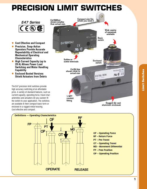
L i m i t S w i t c h e sl Cost Effective and Compact l Precision, snap-action operators Provide accurate repeatability of Electrical and mechanical operating Characteristics l High Current Capacity (up to 20 a) allows Power Load switching and motor Handling Capability l Enclosed Booted Versions shield actuators from debrisThe E47 precision limit switches provide high accuracy switching at an affordable price. A variety of standard features, such as current capacity, operating force, travel char-acteristics and actuators let you custom fit the switch to your application. The switches are available in their compact basic form or enclosed in a rugged metal housing.Cost effective and compact.Precision Limit switchesE47 SeriesOF – Operating Force RF – Return Force PT – Pre-Travel OT – Operating Travel MD – Movement Differential FP – Free Position OP – Operating PositionRugged die cast aluminum enclosure1⁄2 NPTconduit fittingEnclosed switchWide variety of operators availableBasic switchSolder orscrew terminalsCompact size fits where you need itE47BLS06 shown close toactual sizeE47BMS42 shown smaller than actual size.Definitions — Operating Characteristics0.8 (20)0.67 (17)0.165 (4.2) 0.17 (4.4)L i m i t S w i t c h e ssPECifiCaTionsoperating speed: 0.01 m/second to 1 m/secondoperating frequency:mechanical: 120 operations/minute Electrical: 20 operations/minute mechanical Life:3,000,000 operations maximum Electrical Life:500,000 operations minimum Contact resistance: 15 m Ω insulation resistance: 100 m Ω minimum @ 500 Vdc dielectric strength:Between non-current carrying parts: 1000 Vac, 50/60 hz for 1 minute Between current carrying parts and ground: 2000 Vac, 50/60 hz for 1 minuteambient operating Temperature: Basic: -25 to 80°C (-13 to 176°F) Enclosed: -15 to 80°C (5 to 176°F) Environmental rating Enclosed, mounting Centers: 25.4 mm (1.0 in), #8 screw sizeTerminal screws: Bottom facing M4 x 0.7 (8 – 32) — screws with cup washers will accept 22 to 12 AWG (2.5 sq. mm maximum) Threaded Bushing: 15/32 in Housing material: Mineral filled phenolicEnclosure: Aluminum die casting Conduit fitting on Enclosed Type: 1⁄ NPTEnCLosEd swiTCHEsMODEL NuMBER15 A 20 ADESCRiPTiON SPECiFiCATiONSOF Max: 800 g (28.22 oz) RF Min: 240 g (8.46 oz)PT Max: 2.0 mm (0.079") OT Max: 5.0 mm (0.197") MD Max: 0.1 mm (0.004") OP: 45.8 mm (0.016")OF Max: 640 g (22.57 oz) RF Min: 230 g (8.11 oz)PT Max: 5.0 mm (0.197") OT Max: 6.0 mm (0.236")MD Max: 0.4 mm (0.016")OF Max: 500 g (17.64 oz) RF Min: 100 g (3.53 oz)PT Max: 1.0 mm (0.039") OT Max: 3.5 mm (0.138") MD Max: 0.005 mm (0.012") OP: 49.7 mm (1.957")OF Max: 60 g (2.11 oz) RF Min: 25 g (0.88 oz)PT Max: 13.2 mm (0.520")OT Max: 8.0 mm (0.315")MD Max: 1.0 mm (0.039")0.9(23)0.67(17)1.56(40)0.75 x 0.31(19 x 8)1.73(44)0.76(19)E47BLS06 N/A E47BLS33 N/A E47BLS08 N/A E47BLS14 N/A Booted Plunger Booted Roller Lever Booted Roller Plunger Booted Roller Lever All Dimensions: in (mm)OPPT0.5 x 0.18(13 x 5)0.67(17)OPPT0.47(12)R = 0.67(17)0.91(23)0.67(17)0.08(2.1)5.91(150)1.00(25.5)1.00 (25.4)1.00 (25.4)0.96 (24.5)3.37(85.5)0.25 (6.5)Dia.PT 0.37(9.5)2-M4.0 x 45L i m i t S w i t c h e s0.92(23)M12 P = 10.5 x 0.19(12.7 x 4.8)0.63(16)0.61(15.5)OPPTE47BMS100.47(12)0.92(23)M12 P = 10.33(8.4)0.63(16)0.64(16)0.52(3.1)OPPTR=E47BMS04(7.2)0.28(12)0.480.39(10)0.92(23)0.47(12)R=PT OPE47BMS0220.8(20)0.67(17)1.03(26)0.165(4.2)0.17(4.4)1.94(49)1.0(25.40.47(12)0.17(4.2)0.69(17.5)0.19(5)0.36(9.2)2.5(64)0.04(1)0.55(14)OP FPR=t=E47BMS22M12 P = 10.5 x 0.19(12.7 x 4.8)0.92(23)0.63(16)0.61(15.5)OPPTE47BMS110.8(20)0.67(17)1.03(26)0.04(1)t=0.55(14)(9.5 x 4.0)OPFP 1.6(49)R=0.37 x 0.16E47BMS420.67(17) 1.05(27)R=0.04(1.0)t= 1.03(26)OPFP0.55(14)0.37 x 0.16(9.5 x 4.0)0.8(20)E47BMS30(9.5 x 5.0)0.37 x 0.191.16(29)1.52(39)0.87(22)0.8(21)2.3(59)R=0.75(19)2 - M4.02 - M4.0 x 30.028(7)OPFPE47BMS43To OrderBASiC SWiTChES MODEL NO. MODEL NO DESCRiPTiON 15 A 20 A E47BMS02 Straight plunger E47BMS22 E47CMS22 Straight lever E47BMS04 E47CMS04 Extended straight plunger E47BMS10 Roller plunger E47BMS11 Cross roller plunger E47BMS42 Extended roller lever E47BMS30 E47CMS30 Roller leverE47BMS43 Extended adjustable rollerDimensions: in (mm) Dimensions: in (mm)Dimensions: in (mm)Dimensions: in (mm) Dimensions: in (mm) Dimensions: in (mm)Dimensions: in (mm)Dimensions: in (mm)0.9(23)0.67(17)Dimensions: mm (in)PT0.47(12)R =E47BLS06Dimensions: in (mm)。
半导体传感器AD7357YRUZ中文规格书
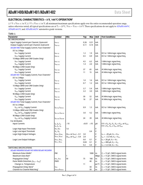
ADuM1400/ADuM1401/ADuM1402Data SheetRev. L | Page 6 of 31 ELECTRICAL CHARACTERISTICS—3 V, 105°C OPERATION 1 2.7 V ≤ V DD1 ≤ 3.6 V , 2.7 V ≤ V DD2 ≤ 3.6 V; all minimum/maximum specifications apply over the entire recommended operation range, unless otherwise noted; all typical specifications are at T A = 25°C, V DD1 = V DD2 = 3.0 V . These specifications do not apply to ADuM1400W , ADuM1401W , and ADuM1402W automotive grade versions. Table 2.ParameterSymbol Min Typ Max Unit Test Conditions DC SPECIFICATIONSInput Supply Current per Channel, QuiescentI DDI (Q) 0.26 0.31 mA Output Supply Current per Channel, QuiescentI DDO (Q) 0.11 0.14 mA ADuM1400 Total Supply Current, Four Channels 2DC to 2 MbpsV DD1 Supply CurrentI DD1 (Q) 1.2 1.9 mA DC to 1 MHz logic signal freq. V DD2 Supply CurrentI DD2 (Q) 0.5 0.9 mA DC to 1 MHz logic signal freq. 10 Mbps (BRW and CRW Grades Only)V DD1 Supply CurrentI DD1 (10) 4.5 6.5 mA 5 MHz logic signal freq. V DD2 Supply CurrentI DD2 (10) 1.4 2.0 mA 5 MHz logic signal freq. 90 Mbps (CRW Grade Only)V DD1 Supply CurrentI DD1 (90) 37 65 mA 45 MHz logic signal freq. V DD2 Supply CurrentI DD2 (90) 11 15 mA 45 MHz logic signal freq. ADuM1401 Total Supply Current, Four Channels 2DC to 2 MbpsV DD1 Supply CurrentI DD1 (Q) 1.0 1.6 mA DC to 1 MHz logic signal freq. V DD2 Supply CurrentI DD2 (Q) 0.7 1.2 mA DC to 1 MHz logic signal freq. 10 Mbps (BRW and CRW Grades Only)V DD1 Supply CurrentI DD1 (10) 3.7 5.4 mA 5 MHz logic signal freq. V DD2 Supply CurrentI DD2 (10) 2.2 3.0 mA 5 MHz logic signal freq. 90 Mbps (CRW Grade Only)V DD1 Supply CurrentI DD1 (90) 30 52 mA 45 MHz logic signal freq. V DD2 Supply CurrentI DD2 (90) 18 27 mA 45 MHz logic signal freq. ADuM1402 Total Supply Current, Four Channels 2DC to 2 MbpsV DD1 or V DD2 Supply CurrentI DD1 (Q), I DD2 (Q) 0.9 1.5 mA DC to 1 MHz logic signal freq. 10 Mbps (BRW and CRW Grades Only)V DD1 or V DD2 Supply CurrentI DD1 (10), I DD2 (10) 3.0 4.2 mA 5 MHz logic signal freq. 90 Mbps (CRW Grade Only)V DD1 or V DD2 Supply CurrentI DD1 (90), I DD2 (90) 24 39 mA 45 MHz logic signal freq. For All ModelsInput CurrentsI IA , I IB , I IC , I ID , I E1, I E2 −10 +0.01 +10µA 0 V ≤ V IA , V IB , V IC , V ID ≤ V DD1 or V DD2, 0 V ≤ V E1, V E2 ≤ V DD1 or V DD2 Logic High Input ThresholdV IH , V EH 1.6 V Logic Low Input ThresholdV IL , V EL 0.4 V Logic High Output VoltagesV OAH , V OBH , V OCH , V ODH (V DD1 or V DD2) − 0.1 3.0 V I Ox = −20 µA, V Ix = V IxH (V DD1 or V DD2) − 0.4 2.8 V I Ox = −3.2 mA, V Ix = V IxH Logic Low Output Voltages V OAL , V OBL , V OCL , V ODL 0.0 0.1 VI Ox = 20 µA, V Ix = V IxL 0.04 0.1 VI Ox = 400 µA, V Ix = V IxL0.2 0.4 V I Ox = 3.2 mA, V Ix = V IxLSWITCHING SPECIFICATIONSADuM1400ARW /ADuM1401ARW /ADuM1402ARWMinimum Pulse Width 3PW 1000 ns C L = 15 pF, CMOS signal levels Maximum Data Rate 41 Mbps C L = 15 pF, CMOS signal levels Propagation Delay 5t PHL , t PLH 50 75 100 ns C L = 15 pF, CMOS signal levels Pulse Width Distortion, |t PLH − t PHL |5PWD 40 ns C L = 15 pF, CMOS signal levels Change vs. Temperature11 ps/°C C L = 15 pF, CMOS signal levels Propagation Delay Skew 6t PSK50 ns C L = 15 pF, CMOS signal levels Channel-to-Channel Matching 7 t PSKCD /t PSKOD50 ns C L = 15 pF, CMOS signal levelsADuM1400/ADuM1401/ADuM1402 Data SheetELECTRICAL CHARACTERISTICS—MIXED 5 V/3 V OR 3 V/5 V, 105°C OPERATION15 V/3 V operation: 4.5 V ≤ V DD1 ≤ 5.5 V, 2.7 V ≤ V DD2 ≤ 3.6 V; 3 V/5 V operation: 2.7 V ≤ V DD1 ≤ 3.6 V, 4.5 V ≤ V DD2 ≤ 5.5 V; all minimum/maximum specifications apply over the entire recommended operation range, unless otherwise noted; all typical specifications are at T A = 25°C; V DD1 = 3.0 V, V DD2 = 5 V or V DD1 = 5 V, V DD2 = 3.0 V. These specifications do not apply to ADuM1400W, ADuM1401W, and ADuM1402W automotive grade versions.Table 3.Parameter Symbol Min Typ Max Unit Test ConditionsDC SPECIFICATIONSInput Supply Current per Channel, Quiescent I DDI (Q)5 V/3 V Operation 0.50 0.53 mA3 V/5 V Operation 0.26 0.31 mAOutput Supply Current per Channel, Quiescent I DDO (Q)5 V/3 V Operation 0.11 0.14 mA3 V/5 V Operation 0.19 0.21 mAADuM1400 Total Supply Current, Four Channels2DC to 2 MbpsV DD1 Supply Current I DD1 (Q)5 V/3 V Operation 2.2 2.8 mA DC to 1 MHz logic signal freq.3 V/5 V Operation 1.2 1.9 mA DC to 1 MHz logic signal freq.V DD2 Supply Current I DD2 (Q)5 V/3 V Operation 0.5 0.9 mA DC to 1 MHz logic signal freq.3 V/5 V Operation 0.9 1.4 mA DC to 1 MHz logic signal freq.10 Mbps (BRW and CRW Grades Only)V DD1 Supply Current I DD1 (10)5 V/3 V Operation 8.6 10.6 mA 5 MHz logic signal freq.3 V/5 V Operation 4.5 6.5 mA 5 MHz logic signal freq.V DD2 Supply Current I DD2 (10)5 V/3 V Operation 1.4 2.0 mA 5 MHz logic signal freq.3 V/5 V Operation 2.6 3.5 mA 5 MHz logic signal freq.90 Mbps (CRW Grade Only)V DD1 Supply Current I DD1 (90)5 V/3 V Operation 70 100 mA 45 MHz logic signal freq.3 V/5 V Operation 37 65 mA 45 MHz logic signal freq.V DD2 Supply Current I DD2 (90)5 V/3 V Operation 11 15 mA 45 MHz logic signal freq.3 V/5 V Operation 18 25 mA 45 MHz logic signal freq.ADuM1401 Total Supply Current, Four Channels2DC to 2 MbpsV DD1 Supply Current I DD1 (Q)5 V/3 V Operation 1.8 2.4 mA DC to 1 MHz logic signal freq.3 V/5 V Operation 1.0 1.6 mA DC to 1 MHz logic signal freq.V DD2 Supply Current I DD2 (Q)5 V/3 V Operation 0.7 1.2 mA DC to 1 MHz logic signal freq.3 V/5 V Operation 1.2 1.8 mA DC to 1 MHz logic signal freq.10 Mbps (BRW and CRW Grades Only)V DD1 Supply Current I DD1 (10)5 V/3 V Operation 7.1 9.0 mA 5 MHz logic signal freq.3 V/5 V Operation 3.7 5.4 mA5 MHz logic signal freq.V DD2 Supply Current I DD2 (10)5 V/3 V Operation 2.2 3.0 mA 5 MHz logic signal freq.3 V/5 V Operation 4.1 5.0 mA 5 MHz logic signal freq.Rev. L | Page 8 of 31。
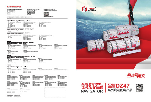
德力西电气全新DZ47系列终端配电产品样本
产品选型及订货号
安装尺寸
附录
性能影响因素
01-01 02-03 04-19
20-21 22-34 35-42 43-43 44-45
产品选型规则
产品选型
说明
DZ47s 1 C 16 R100 G
产品名称
DZ47s:小型标准断路器 DZ47sLE:小型漏电保护断路器 DZ47P:“相线 + 中性线”断路器 DZ47PLE:“相线 + 中性线”漏电保护断路器 DZ47-125:大电流断路器 DZ47LE-125:大电流漏电保护断路器 DZ47G:隔离开关 DZ47X:框缘式插座 ( 模数化插座) DZ47Y:电源类电涌保护器
产品简介
产品概览
DZ47-125
DZ47LE-125
DZ47G
DZ47X
GB16917.1 IEC/EN61009-1 CCC 1P+N 6-40 50/60
GB14048.2 IEC/EN60947-2 CCC 1P,2P,3P,4P 63-125 50/60
GB14048.2 IEC60947-2 CCC 1P+N,2P,3P,3P+N,4P 63-125 50/60
产品细节展示
安装方向灵活
安装在35mm标准N导级轨指示上
N
安装方向灵活
附件安装及定位孔
移印及电气原理图
25m产m品安装示意3图 N.m
04
DZ47s 小型标准断路器
功能和特性
电气特性
IP40
额定绝缘电压 Ui
ห้องสมุดไป่ตู้
(V) 250( 相对地 ) / 500( 相对相 )
最大工作电压 UBmax
赛米控丹佛斯电子 SK75GD12T4ETE2 数据表

© by SEMIKRONRev. 1.0–08.01.20201®E2IGBT moduleSK75GD12T4ETE2Features*•Low inductive design•Press-Fit contact technology•Rugged mounting due to integrated mounting clamps•Heat transfer and insulation through direct copper bonded aluminium oxide ceramic (DBC)•Trench4 IGBT technology•Robust and soft switching CAL4F diode technology•Integrated NTC temperature sensor •UL recognized file no. E 63 532Typical Applications•Motor drives •Servo drives •Air conditioning •Auxiliary Inverters •UPSAbsolute Maximum Ratings SymbolConditions Values UnitIGBT 1V CES T j =25°C1200V I C λpaste =0.8 W/(mK)T j =175°C T s =25°C 88A T s =70°C 71A I Cλpaste =2.5 W/(mK)T j =175°C T s =25°C 113A T s =70°C 92A I Cnom 75A I CRM I CRM = 3 x I Cnom 225A V GES -20 (20)V t psc V CC =800V V GE ≤ 15V V CES ≤ 1200VT j =150°C10µs T j-40 (175)°CAbsolute Maximum Ratings SymbolConditions Values UnitDiode 1V RRM T j =25°C1200V I F λpaste =0.8 W/(mK)T j =175°C T s =25°C 79A T s =70°C 62A I F λpaste =2.5 W/(mK)T j =175°C T s =25°C 101A T s =70°C81A I Fnom 75A I FRM I FRM = 2 x I Fnom 150A I FSM 10ms sin 180°T j =25°C 430A T j =150°C430A T j-40 (175)°CAbsolute Maximum Ratings SymbolConditions Values UnitModule I t(RMS)∆T terminal at PCB joint = 30 K, per pin30A T stg -40...125°C V isolAC, sinusoidal, t =1min2500V2Rev. 1.0–08.01.2020© by SEMIKRON®E2IGBT moduleSK75GD12T4ETE2Features*•Low inductive design•Press-Fit contact technology•Rugged mounting due to integrated mounting clamps•Heat transfer and insulation through direct copper bonded aluminium oxide ceramic (DBC)•Trench4 IGBT technology•Robust and soft switching CAL4F diode technology•Integrated NTC temperature sensor •UL recognized file no. E 63 532Typical Applications•Motor drives •Servo drives •Air conditioning •Auxiliary Inverters •UPSIGBT 1V CE(sat)I C =75A V GE =15V chiplevel T j =25°C 1.85 2.10V T j =150°C 2.25 2.45V V CE0chiplevel T j =25°C 0.800.90V T j =150°C 0.700.80V r CEV GE =15V chiplevelT j =25°C 1416m ΩT j =150°C2122m ΩV GE(th)V GE = V CE , I C =3mA5 5.8 6.5V I CES V GE =0V,V CE =1200V, T j =25°C 1mA C ies V CE =25V V GE =0Vf =1MHz 4.4nF C oes f =1MHz 0.29nF C res f =1MHz0.235nF Q G V GE =-15V ... +15V 553nC R Gint T j =25°C 10Ωt d(on)V CC =600V I C =75AV GE =+15/-15V R G on =1.1ΩR G off =1.1Ωdi/dt on =2410A/µs di/dt off =593A/µs dv/dt =4035V/µsT j =150°C 129ns t r T j =150°C 42ns E on T j =150°C 6.62mJ t d(off)T j =150°C 333ns t f T j =150°C 65ns E off T j =150°C 7.11mJ R th(j-s)per IGBT, λpaste =0.8 W/(mK)0.61K/W R th(j-s)per IGBT, λpaste =2.5 W/(mK)0.39K/WCharacteristics SymbolConditionsmin.typ.max.UnitDiode 1V F I F =75A chiplevel T j =25°C 2.17 2.49V T j =150°C 2.11 2.42V V F0chiplevel T j =25°C 1.30 1.50V T j =150°C 0.90 1.10V r F chiplevelT j =25°C 1213m ΩT j =150°C1618m ΩI RRM I F =75A di/dt off =2410A/µs V GE =-15VV CC =600VT j =150°C 114A Q rr T j=150°C11.22µC E rr T j =150°C 4.41mJ R th(j-s)per Diode, λpaste =0.8 W/(mK)0.82K/W R th(j-s)per Diode, λpaste =2.5 W/(mK)0.55K/W© by SEMIKRONRev. 1.0–08.01.20203®E2IGBT moduleSK75GD12T4ETE2Features*•Low inductive design•Press-Fit contact technology•Rugged mounting due to integrated mounting clamps•Heat transfer and insulation through direct copper bonded aluminium oxide ceramic (DBC)•Trench4 IGBT technology•Robust and soft switching CAL4F diode technology•Integrated NTC temperature sensor •UL recognized file no. E 63 532Typical Applications•Motor drives •Servo drives •Air conditioning •Auxiliary Inverters •UPSModule M s to heatsink 1.62.3Nm wweight35gCharacteristics SymbolConditionsmin.typ.max.UnitTemperature Sensor R 100T r =100°C493 ± 5%ΩB 100/125R (T)=R 100exp[B 100/125(1/T-1/T 100)]; T[K];3550 ±2%K4Rev. 1.0–08.01.2020© by SEMIKRON© by SEMIKRON Rev. 1.0–08.01.202056Rev. 1.0–08.01.2020© by SEMIKRON© by SEMIKRON Rev. 1.0–08.01.20207This is an electrostatic discharge sensitive device (ESDS), international standard IEC 60747-1, chapter IX.*IMPORTANT INFORMATION AND WARNINGSThe specifications of SEMIKRON products may not be considered as guarantee or assurance of product characteristics ("Beschaffenheitsgarantie"). The specifications of SEMIKRON products describe only the usual characteristics of products to be expected in typical applications, which may still vary depending on the specific application. Therefore, products must be tested for the respective application in advance. Application adjustments may be necessary. The user of SEMIKRON products is responsible for the safety of their applications embedding SEMIKRON products and must take adequate safety measures to prevent the applications from causing a physical injury, fire or other problem if any of SEMIKRON products become faulty. The user is responsible to make sure that the application design is compliant with all applicable laws, regulations, norms and standards. Except as otherwise explicitly approved by SEMIKRON in a written document signed by authorized representatives of SEMIKRON, SEMIKRON products may not be used in any applications where a failure of the product or any consequences of the use thereof can reasonably be expected to result in personal injury. No representation or warranty is given and no liability is assumed with respect to the accuracy, completeness and/or use of any information herein, including without limitation, warranties of non-infringement of intellectual property rights of any third party. SEMIKRON does not assume any liability arising out of the applications or use of any product; neither does it convey any license under its patent rights, copyrights, trade secrets or other intellectual property rights, nor the rights of others. SEMIKRON makes no representation or warranty of non-infringement or alleged non-infringement of intellectual property rights of any third party which may arise from applications. Due to technical requirements our products may contain dangerous substances. For information on the types in question please contact the nearest SEMIKRON sales office. This document supersedes and replaces all information previously supplied and may be superseded by updates. SEMIKRON reserves the right to make changes.8。
- 1、下载文档前请自行甄别文档内容的完整性,平台不提供额外的编辑、内容补充、找答案等附加服务。
- 2、"仅部分预览"的文档,不可在线预览部分如存在完整性等问题,可反馈申请退款(可完整预览的文档不适用该条件!)。
- 3、如文档侵犯您的权益,请联系客服反馈,我们会尽快为您处理(人工客服工作时间:9:00-18:30)。
A CASE CODE See Table of Dimensions.
2 STYLE NUMBER 0 = Bare case. 2 = Outer plastic film insulation. 6 = High temperature film insulation (above + 125°C).
X0 CAPACITANCE TOLERANCE X0 = ± 20% X9 = ± 10% X5 = ± 5%
025 DC VOLTAGE RATING AT + 85°C This is expressed in volts. To complete the three-digit block, zero A decimal point is indicated by an "R" (6R3 = 6.3 volts).
ORDERING INFORMATION
CT79 735D 735DE MODEL
226 CAPACITANCE This is expressed in picofarads. The first two digits are the significant figures. The third is the number of zeros to follow.
STANDARD RATINGS
CASE CODE A A A B B B C D C D A A A A B B B B C D D C C D D MAX DF at + 20°C (%) 15 21 34 40 90 106 50 72 172 170 13 21 25 30 30 30 65 74 44 46 57 92 137 114 138 MAX DCL MAX IMP. IN µA at MAX CAP. CHANGE at - 55°C + 85°C & (%) at (Ω) + 20°C + 125°C - 55°C + 85°C + 125°C 60 81 80 30 46 48 25 22 36 22 100 85 84 82 45 40 52 54 25 20 22 36 36 23 24 1.0 1.5 2.0 1.0 2.0 2.0 2.0 3.0 5.0 6.0 1.0 1.5 2.0 2.0 1.0 1.0 2.0 2.0 2.0 3.0 3.0 4.0 5.0 7.0 7.0 2.0 3.0 9.0 6.5 10 10 16 14 20 24 2.0 3.0 6.0 6.0 7.0 7.0 10 10 15 16 16 16 20 25 25 -40 -41 -42 -44 -60 -68 -64 -80 -90 -90 -36 -40 -40 -40 -32 -35 -54 -60 -65 -80 -80 -80 -80 -88 -88 +14 +15 +16 +16 +20 +20 +18 +25 +25 +25 +14 +15 +16 +16 +14 +14 +17 +19 +18 +25 +25 +25 +25 +30 +30 +16 +16 +16 +18 +20 +20 +20 +25 +25 +25 +16 +16 +16 +16 +16 +16 +18 +20 +20 +25 +25 +25 +25 +30 +30 MAX RMS RIPPLE CURRENT 40KHz (mA) 960 820 820 1370 1285 1255 1900 2390 1615 2265 855 820 820 820 1275 1300 1195 1195 1800 2490 2360 1720 1720 2360 2360 47
Packaging: The use of formed plastic trays for packaging this type of axial lead component is standard. Tape and reel is not recommended due to the unit weight.
• For - 55°C to + 200°C operation • All tantalum case • Glass to tantalum hermetic seal • Low ESR • High CV per unit volume • Extremely low leakage current • High permissible ripple current • 3 volts reverse voltage capability
Capacitance Tolerance: At 120 Hz, + 25°C. ± 20% standard. ± 10%, ± 5% available as special. DC Leakage Current (DCL Max.): At + 25°C and above: Leakage current shall not exceed the values listed in the Standard Ratings Tables.
WEIGHT IN GRAMS (Max.) 2.6 6.2 11.6 17.7
*For insulated parts, add 0.007" [0.178] to the diameter. The insulation shall lap over the ends of the capacitor body.
元器件交易网
735D, 735DE, CT79 (CECC 30202)
Vishay Tansitor
STANDARD RATINGS
MAX DF at + 20°C (%) 10 20 22 25 42 55 40 37 40 80 95 92 103 7 11 13 16 21 35 35 35 30 48 35 48 60 60 82 7 10 11 15 25 30 23 23 37 43 43 45 MAX DCL MAX IMP. IN µA at MAX CAP. CHANGE at - 55°C + 85°C & (%) at (Ω) + 20°C + 125°C - 55°C + 85°C + 125°C 90 100 100 50 62 60 30 24 23 42 42 25 25 140 140 130 120 50 62 60 33 27 48 24 48 48 24 26 175 200 190 60 60 62 35 27 52 52 30 30 1.0 1.5 1.5 1.0 2.0 2.0 2.0 3.0 3.0 5.0 6.0 8.0 8.0 1.0 1.5 1.5 2.0 1.0 2.0 2.0 2.0 3.0 7.0 3.0 7.0 7.0 8.0 8.0 1.0 1.5 1.5 1.0 2.0 2.0 2.0 3.0 7.0 8.0 8.0 9.0 2.0 3.0 3.0 7.0 10 12 14 18 18 20 24 32 32 2.0 3.0 3.0 9.0 9.0 10 10 13 20 28 20 28 28 32 32 2.0 4.0 4.0 8.0 10 12 12 22 28 32 32 36 -28 -28 -28 -28 -35 -45 -58 -75 -80 -80 -80 -82 -84 -20 -20 -24 -28 -28 -35 -48 -52 -60 -70 -68 -76 -80 -80 -80 -20 -20 -24 -24 -40 -32 -48 -58 -60 -65 -75 -80 +14 +16 +16 +14 +16 +18 +18 +25 +25 +25 +25 +25 +25 +10 +12 +14 +16 +13 +15 +14 +18 +25 +25 +25 +25 +25 +25 +25 +10 +12 +12 +13 +15 +15 +14 +23 +25 +25 +25 +25 +16 +16 +16 +16 +16 +18 +20 +25 +25 +25 +25 +25 +30 +12 +12 +14 +16 +15 +15 +15 +20 +25 +25 +25 +25 +25 +25 +25 +12 +12 +12 +15 +15 +15 +15 +23 +25 +25 +25 +25 MAX RMS RIPPLE CURRENT 40KHz (mA) 820 760 760 1230 1215 1215 1760 2100 2300 1585 1585 2300 2300 800 715 715 715 1215 1130 1130 1615 1865 1400 2025 1400 1400 1940 1865 660 580 580 1285 1285 1245 1525 1900 1375 1375 1900 1900 Document Number: 40053 Revision 17-Oct-03
