PAC390QR中文资料
艾茨顿199034产品说明说明书

Eaton 199034Eaton Moeller® series Rapid Link - Speed controllers, 8.5 A, 4 kW, Sensor input 4, Actuator output 2, 230/277 V AC, PROFINET, HAN Q4/2, with braking resistance, with fanGeneral specificationsEaton Moeller® series Rapid Link Speed controller199034195 mm270 mm 220 mm 3.65 kgUL 61800-5-1 IEC/EN 61800-5-1 UL approval RoHS CERASP5-8422PNT-4120101S1Product NameCatalog NumberProduct Length/Depth Product Height Product Width Product Weight Certifications Catalog Notes Model Code3 fixed speeds and 1 potentiometer speedcan be switched over from U/f to (vector) speed control Connection of supply voltage via adapter cable on round or flexible busbar junction480 VIs the panel builder's responsibility. The specifications for the switchgear must be observed.400 V AC, 3-phase480 V AC, 3-phaseMeets the product standard's requirements.4 kW500 VMeets the product standard's requirements.-40 °C380 VThermo-click with safe isolationBraking resistance2 Actuator outputsIGBT inverterKey switch position AUTOPC connectionKey switch position HANDSelector switch (Positions: REV - OFF - FWD)FanKey switch position OFF/RESETPTC thermistor monitoringControl unitInternal DC linkBreaking resistanceTwo sensor inputs through M12 sockets (max. 150 mA) for quick stop and interlocked manual operation0 Hz Generation change from RA-SP to RASP 4.0Generation change RAMO4 to RAMO5Generation change from RA-MO to RAMO 4.0Configuration to Rockwell PLC for Rapid LinkGeneration Change RA-SP to RASP5Generation Change RASP4 to RASP5Rapid Link 5 - brochureDA-SW-USB Driver DX-COM-STICK3-KITDA-SW-USB Driver PC Cable DX-CBL-PC-1M5DA-SW-Driver DX-CBL-PC-3M0DA-SW-drivesConnect - installation helpDA-SW-drivesConnect - InstallationshilfeDA-SW-drivesConnectMaterial handling applications - airports, warehouses and intra-logistics ETN.RASP5-8422PNT-4120101S1.edzIL034093ZUramo5_v36.dwgrasp5_v36.stpDA-DC-00003964.pdfDA-DC-00004184.pdfDA-DC-00004514.pdfDA-DC-00004508.pdfeaton-bus-adapter-rapidlink-speed-controller-dimensions-002.eps eaton-bus-adapter-rapidlink-speed-controller-dimensions-003.eps eaton-bus-adapter-rapidlink-speed-controller-dimensions.epseaton-bus-adapter-rapidlink-speed-controller-dimensions-004.epsMains voltage - max10.11 Short-circuit ratingRated operational voltage10.4 Clearances and creepage distancesOutput at quadratic load at rated output voltage - max Output voltage - max10.2.3.1 Verification of thermal stability of enclosures Ambient storage temperature - minMains voltage - minFitted with:Output frequency - min Applikasjonsmerknader BrosjyrereCAD model Installeringsinstruksjoner mCAD model SertifiseringsrapporterTegningerStarting current - max200 %, IH, max. starting current (High Overload), For 2 seconds every 20 seconds, Power sectionRated conditional short-circuit current (Iq)10 kAAmbient operating temperature - max40 °CCommunication interfacePROFINET, optionalAssigned motor power at 115/120 V, 60 Hz, 1-phase5 HPOutput frequency - max500 HzSwitching frequency8 kHz, 4 - 32 kHz adjustable, fPWM, Power section, Main circuitFeaturesParameterization: drivesConnect mobile (App) Parameterization: FieldbusInternal and on heat sink, temperature-controlled Fan Parameterization: drivesConnectParameterization: KeypadAmbient operating temperature - min-10 °CBraking current≤ 0.6 A (max. 6 A for 120 ms), Actuator for external motor brakeNumber of HW-interfaces (serial TTY)10.6 Incorporation of switching devices and componentsDoes not apply, since the entire switchgear needs to be evaluated.Nominal output current I2N8.5 A10.2.6 Mechanical impactDoes not apply, since the entire switchgear needs to be evaluated.10.3 Degree of protection of assembliesDoes not apply, since the entire switchgear needs to be evaluated.Product categorySpeed controllerRadio interference classC2, C3: depending on the motor cable length, the connected load, and ambient conditions. External radio interference suppression filters (optional) may be necessary.C1: for conducted emissions onlyHeat dissipation capacity Pdiss0 WRated control voltage (Uc)230/277 V AC (external brake 50/60 Hz)24 V DC (-15 %/+20 %, external via AS-Interface® plug)Assigned motor power at 460/480 V, 60 Hz, 3-phase5 HPNumber of HW-interfaces (RS-422)Mains current distortion120 %ProtocolPROFINET IO10.9.2 Power-frequency electric strengthIs the panel builder's responsibility.Overvoltage categoryIIIDegree of protectionIP65NEMA 12Ambient storage temperature - max70 °CRated impulse withstand voltage (Uimp)2000 VConnectionPlug type: HAN Q4/2Overload currentFor 60 s every 600 sAt 40 °CFunctionsFor actuation of motors with mechanical brake3 fixed speeds1 potentiometer speedBrake chopper with braking resistance for dynamic braking4-quadrant operation possibleOutput at linear load at rated output voltage - max4 kWMains voltage tolerance380 - 480 V (-10 %/+10 %, at 50/60 Hz)Leakage current at ground IPE - max3.5 mAConverter typeU converter10.2.2 Corrosion resistanceMeets the product standard's requirements.Supply frequency50/60 Hz10.2.4 Resistance to ultra-violet (UV) radiationMeets the product standard's requirements.10.2.7 InscriptionsMeets the product standard's requirements.Shock resistance15 g, Mechanical, According to IEC/EN 60068-2-27, 11 ms, Half-sinusoidal shock 11 ms, 1000 shocks per shaftApplication in domestic and commercial area permittedYesNumber of inputs (analog)Number of phases (output)310.12 Electromagnetic compatibilityIs the panel builder's responsibility. The specifications for the switchgear must be observed.10.2.5 LiftingDoes not apply, since the entire switchgear needs to be evaluated.Number of HW-interfaces (RS-485)1Number of HW-interfaces (industrial ethernet)Efficiency98 % (η)System configuration typePhase-earthed AC supply systems are not permitted.AC voltageCenter-point earthed star network (TN-S network)10.8 Connections for external conductorsIs the panel builder's responsibility.Switch-on threshold for the braking transistor765 VDCProtectionFinger and back-of-hand proof, Protection against direct contact (BGV A3, VBG4)Braking voltage230/277 V AC -15 % / +10 %, Actuator for external motor brakeApplication in industrial area permittedYesClimatic proofingIn accordance with IEC/EN 50178< 95 %, no condensation10.9.3 Impulse withstand voltageIs the panel builder's responsibility.Overload current IL at 150% overload12.7 AInput current ILN at 150% overload7.8 ANumber of HW-interfaces (RS-232)Number of inputs (digital)4Current limitationAdjustable, motor, main circuit0.8 - 8.5 A, motor, main circuitCable lengthC3 ≤ 25 m, maximum motor cable lengthC1 ≤ 1 m, maximum motor cable lengthC2 ≤ 5 m, maximum motor cable length10.5 Protection against electric shockDoes not apply, since the entire switchgear needs to beevaluated.Mounting positionVerticalMains switch-on frequencyMaximum of one time every 60 seconds10.13 Mechanical functionThe device meets the requirements, provided the information in the instruction leaflet (IL) is observed.10.9.4 Testing of enclosures made of insulating materialIs the panel builder's responsibility.Heat dissipation per pole, current-dependent Pvid0 WElectromagnetic compatibility1st and 2nd environments (according to EN 61800-3)Resolution0.1 Hz (Frequency resolution, setpoint value)Assigned motor power at 460/480 V, 60 Hz5 HPRelative symmetric net voltage tolerance10 %Rated operational current (Ie)8.5 A at 150% overload (at an operating frequency of 8 kHz and an ambient air temperature of +40 °C)Number of outputs (analog)Rated operational power at 380/400 V, 50 Hz, 3-phase4 kWNumber of HW-interfaces (USB)Operating modeSensorless vector control (SLV)PM and LSPM motorsSynchronous reluctance motorsBLDC motorsU/f controlRated frequency - min45 HzDelay time< 10 ms, On-delay< 10 ms, Off-delayNumber of outputs (digital)2Power consumption95 W10.2.3.2 Verification of resistance of insulating materials to normal heatMeets the product standard's requirements.10.2.3.3 Resist. of insul. mat. to abnormal heat/fire by internal elect. effectsMeets the product standard's requirements.Number of HW-interfaces (other)Rated frequency - max66 HzVibrationResistance: According to IEC/EN 60068-2-6Resistance: 6 Hz, Amplitude 0.15 mmResistance: 10 - 150 Hz, Oscillation frequency Resistance: 57 Hz, Amplitude transition frequency on accelerationShort-circuit protection (external output circuits)Type 1 coordination via the power bus' feeder unit, Main circuit10.7 Internal electrical circuits and connectionsIs the panel builder's responsibility.Braking torque≤ 30 % (I/Ie)Adjustable to 100 % (I/Ie), DC - Main circuitRelative symmetric net frequency tolerance10 %10.10 Temperature riseThe panel builder is responsible for the temperature rise calculation. Eaton will provide heat dissipation data for the devices.Number of HW-interfaces (parallel)Assigned motor power at 230/240 V, 60 Hz, 1-phase5 HPInterfacesNumber of slave addresses: 31 (AS-Interface®)Eaton Corporation plc Eaton House30 Pembroke Road Dublin 4, Ireland © 2023 Eaton. Med enerett.Eaton is a registered trademark.All other trademarks are property of their respectiveowners./socialmediaMax. total power consumption from AS-Interface® power supply unit (30 V): 250 mASpecification: S-7.4 (AS-Interface®)351.6 W at 25% current and 0% speed 53.8 W at 25% current and 50% speed 60.9 W at 50% current and 0% speed 64 W at 50% current and 90% speed 65.4 W at 50% current and 50% speed 85.1 W at 100% current and 0% speed 94 W at 100% current and 50% speed 95.3 W at 100% current and 90% speed 2Max. 2000 mAbove 1000 m with 1 % performance reduction per 100 mNumber of phases (input)Heat dissipation at current/speed Number of interfaces (PROFINET)Altitude。
法国百福马涡旋压缩机性能参数
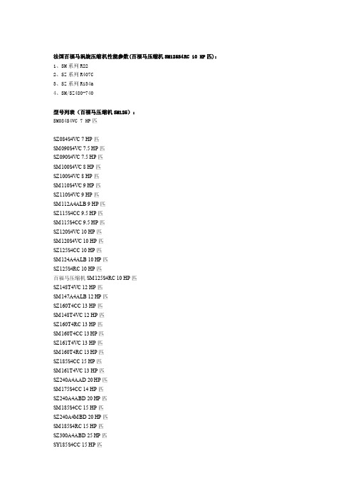
法国百福马涡旋压缩机性能参数(百福马压缩机SM125S4RC 10 HP匹):1、SM系列R222、SZ系列R407C3、SZ系列R134a4、SM/SZ480-740型号列表(百福马压缩机SM125):SM084S4VC 7 HP匹SZ084S4VC 7 HP匹SM090S4VC 7.5 HP匹SZ090S4VC 7.5 HP匹SM100S4VC 8 HP匹SZ100S4VC 8 HP匹SM110S4VC 9 HP匹SZ110S4VC 9 HP匹SM112A4ALB 9 HP匹SZ115S4CC 9.5 HP匹SM115S4CC 9.5 HP匹SZ120S4VC 10 HP匹SM120S4VC 10 HP匹SZ125S4CC 10 HP匹SM124A4ALB 10 HP匹SZ125S4RC 10 HP匹百福马压缩机SM125S4RC 10 HP匹SZ148T4VC 12 HP匹SM147A4ALB 12 HP匹SZ160T4CC 13 HP匹SM148T4VC 12 HP匹SZ160T4RC 13 HP匹SM160T4CC 13 HP匹SZ161T4VC 13 HP匹SM160T4RC 13 HP匹SZ185S4CC 15 HP匹SM161T4VC 13 HP匹SZ240A4AAD 20 HP匹SM175S4CC 14 HP匹SZ240A4ABD 20 HP匹SM185S4CC 15 HP匹SZ240A4MBD 20 HP匹SM185S4RC 15 HP匹SZ300A4ABD 25 HP匹SY185S4CC 15 HP匹SZ300A4MBD 25 HP匹SY240A4ABD 20 HP匹百福马SZ380A4CBE 30 HP匹SY240A4MBD 20 HP匹SH090A4ALC 6.5 HP匹SY300A4ABD 25 HP匹SH105A4ALC 9 HP匹SY300A4MBD 25 HP匹SH120A4ALC 10 HP匹SY380A4CBE 30 HP匹SH161A4ALC 13 HP匹SH140A4ALC 12 HP匹SH184A4ALC 15 HP匹SH300A4ABE 25 HP匹下面是泰戈尔励志经典语录,欢迎阅读。
UC3902中文资料
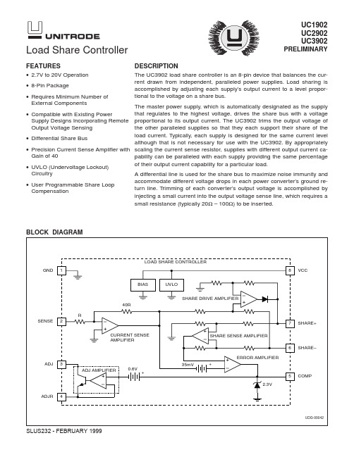
• User Programmable Share Loop Compensation
accommodate different voltage drops in each power converter’s ground return line. Trimming of each converter’s output voltage is accomplished by injecting a small current into the output voltage sense line, which requires a
PARAMETERS
TEST CONDITIONS
MIN TYP MAX UNIT
Share Sense Amplifier
Input Impedance
SHARE+ = 1V, SHARE– = 1V, SENSE = +10mV
10 15
kΩ
200Ω resistor SHARE+ to GND, SHARE– = 1V, SENSE =
PARAMETERS
TEST CONDITIONS
MIN TYP MAX UNIT
Power Supply
Supply Current
SHARE+ = 1V, SENSE = 0V
4
6 mA
VCC = 20V
6
10 mA
Undervoltage Lockout
Startup Voltage
SHARE+ = 0.2V, SENSE = 0V, COMP = 1V
0.12 0.24 0.34 V/µs
2
元器件交易网
UC1902 UC2902 UC3902
中文版MP2905
TA=85 C o TA=25 C
o
42.5 60
57.5 100
Ω Ω ns ns ns ns
oC
说明: 5) 当输入供给电压小于 5V 时,电路能保持工作但效率较低 6) 由设计保证
MP2905 Rev. 1.0 9/18/2015
MPS Proprietary Information. Unauthorized Photocopy and Duplication Prohibited. © 2015. All Rights Reserved.
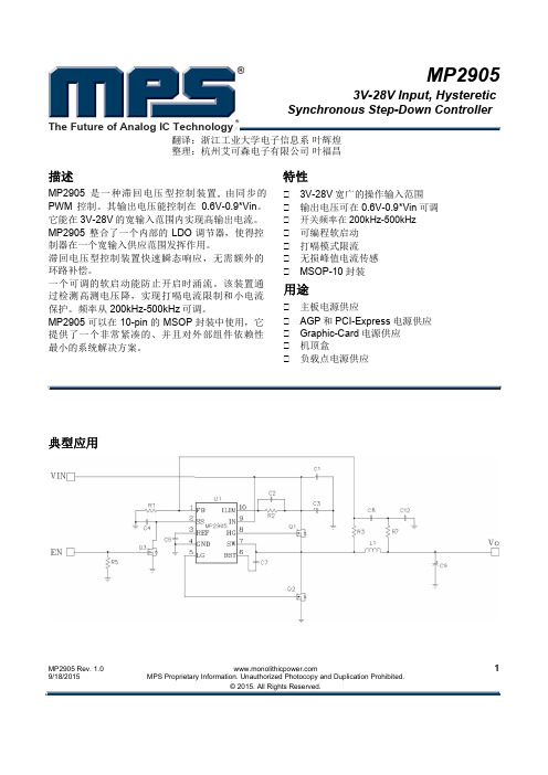
特性
3V-28V 宽广的操作输入范围 输出电压可在 0.6V-0.9*Vin 可调 开关频率在 200kHz-500kHz 可编程软启动 打嗝模式限流 无损峰值电流传感 MSOP-10 封装 主板电源供应 AGP 和 PCI-Express 电源供应 Graphic-Card 电源供应 机顶盒 负载点电源供应
1
FB
2
SS
6
BST
7 8 9
SW HG IN
10
ILIM
MP2905 Rev. 1.0 9/18/2015
MPS Proprietary Information. Unauthorized Photocopy and Duplication Prohibited. © 2015. All Rights Reserved.
1
MP2905- 3V to 28V INPUT, HYSTERETIC SYNCHRONOUS STEP-DOWN CONTROLLER
订购须知
零件号码* MP2905EK 封装 MSOP10 上部标记 2905E 温度 –40C to +85C
PAC500TFQR中文资料
-40 10 MHz
25 Ω Filters 0 S12 (dB)
-20
100 MHz
-40 10 MHz
39 Ω Filters 0 S12 (dB) -10
-20
-30
-40
-50 10 MHz
100 Ω Filter -10
S12 (dB) -20
100 MHz 100 MHz
15 Ω Filter 0
9
Filt6
10
Filt7
11
Filt8
12
GND
GND
24
Filt1
23
Filt2
22
Filt3
21
GND
20
Filt4
19
Filt5
18
GND
17
Filt6
16
Filt7
15
Filt8
14
GND
13
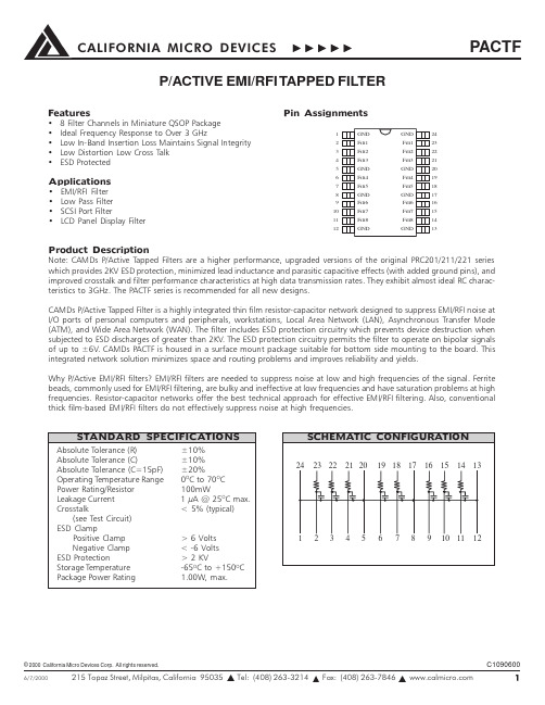
Product Description Note: CAMDs P/Active Tapped Filters are a higher performance, upgraded versions of the original PRC201/211/221 series which provides 2KV ESD protection, minimized lead inductance and parasitic capacitive effects (with added ground pins), and improved crosstalk and filter performance characteristics at high data transmission rates. They exhibit almost ideal RC characteristics to 3GHz. The PACTF series is recommended for all new designs.
金属化聚丙烯抗干扰电容器(X2型)产品规格承认书说明书

产品规格承认书Product Spec Certification客户名:品名:金属化聚丙烯抗干扰电容(X2)型号:客户料号:日期:批准审核拟制金属化聚丙烯膜抗干扰电容器(X2型)产品外形尺寸客户料号容量(μF)容量误差(%)额定电压(VAC)1KDF(%)尺寸加工方式制造商料号W±0.5MMH±0.5MMT±0.5MMP±0.5MML±0.3MMd∮±0.050.01102750.11211510220.6A MPX-103K275VAC-B-C2 0.047102750.11811515250.8A MPX-473K275VAC-C-D1 0.068102750.1101157.5220.6A MPX-683K275VAC-A-B40.1102750.11312610250.6A MPX-104K275VAC-B-C30.1102750.11812615250.8A MPX-104K275VAC-C-D20.1102750.1101157.5220.6A MPX-104K275VAC-A-B40.15102750.11312610250.6A MPX-154K275VAC-B-C30.22102750.1101267.5220.6A MPX-224K275VAC-A-B50.22102750.11312610250.6A MPX-224K275VAC-B-C30.22102750.11812615250.8A MPX-224K275VAC-C-D20.22102750.11314810220.6A MPX-224K275VAC-B-C50.22102750.11814.58.515250.8A MPX-224K275VAC-C-D40.22102750.11813.57.515250.8A MPX-224K275VAC-C-D30.33102750.11314810220.6A MPX-334K275VAC-B-C50.33102750.11813.57.515250.8A MPX-334K275VAC-C-D30.33102750.11814.58.515250.8A MPX-334K275VAC-C-D40.33102750.11815.59.515250.8A MPX-334K275VAC-C-D50.33102750.126.5178.522.5250.8A MPX-334K275VAC-E-E30.47102750.11814.58.515250.8A MPX-474K275VAC-C-D40.47102750.11815.59.515250.8A MPX-474K275VAC-C-D50.47102750.1181910.815250.8A MPX-474K275VAC-C-D70.47102750.126.5191022.5250.8A MPX-474K275VAC-E-E40.68102750.11815.59.515250.8A MPX-684K275VAC-C-D50.68102750.1181910.815250.8A MPX-684K275VAC-C-D70.68102750.126.5191022.5250.8A MPX-684K275VAC-E-E41.0102750.126.5191022.5250.8A MPX-105K275VAC-E-E41.0102750.11815.59.515250.8A MPX-105K275VAC-C-D5芯通电子科技有限公司拟定审核批准金属化聚丙烯膜抗干扰电容器(X2型)编码规则MPX 0.22μF K 275VAC 13*12*6mm P=10mm1、电容器型别2、电容量代码表示方法用电容单位法拉表达,前面两位代表容量大小,第三位数要制定跟随以下101=0.0001μF 104=0.1μF 102=0.001μF 105=1.0μF 103=0.01μF 106=10.0μF 3、电容量偏差4、额定电压代码025002750300030506301000120016002000类型250V275V 300V 305V 630V 1000V 1200V 1600V 2000V5、额定电压别代码PEI-MPX-CBB22-CBB21-CL21-CL22-CBB81-类型PEIMPXCBB22CBB21CL21CL22CBB81代码G J K M 电容量偏差±2.5%±5%±10%±20%MPX -224K 275V AC .-B -C312345676、脚距(mm)7、内部识别码外壳型号金属化聚丙烯膜抗干扰电容器TYPE:MPX产生说明书Rev.11、应用本规范涵盖了金属化聚丙烯介质固定的要求。
美国电解放PDF34K0250E3XN电解放纤维筋电容电流保护器说明说明书
Eaton PDF34K0250E3XNPower Defense Globally Rated 100% UL, Frame 3, Four Pole, 250A, 50kA/480V, PXR20 LSIG w/ CAM Link, ZSI and Relays, No TerminalsEaton Power Defense molded case circuit breakerPDF34K0250E3XN 786679487747109.1 mm 257.1 mm 182.9 mm 7.68 kg Eaton Selling Policy 25-000, one (1) year from the date of installation of theProduct or eighteen (18) months from thedate of shipment of the Product,whichever occurs first.RoHS Compliant CCC MarkedIEC 60947-2Product NameCatalog Number UPCProduct Length/Depth Product Height Product Width Product Weight WarrantyCompliancesCertifications250 AComplete breaker 3Four-pole (100% N)PD3 Global (100% UL) Class APXR 20 LSIGCAM Link600 Vac600 V100% neutral protectionNo Terminals50 kAIC at 480 Vac10 kAIC Icu/ 5 kAIC Ics/ 21 kAIC Icm @690V (IEC)50 kAIC @480V (UL)85 kAIC Icu/ 85 kAIC Ics/ 187 kAIC Icm @240V (IEC)85 kAIC @240V (UL)35 kAIC Icu/ 35 kAIC Ics/ 73.5 kAIC Icm @440V (IEC)25 kAIC @600V (UL/CSA)35 kAIC Icu/ 22.5 kAIC Ics/ 73.5 kAIC Icm @480V Brazil (IEC) 10 kAIC Icu @250 Vdc25 kAIC Icu/ 10 kAIC Ics/ 52.5 kAIC Icm @525V South Africa (IEC)50 kAIC Icu/ 50 kAIC Ics/ 105 kAIC Icm @380-415V (IEC)Eaton Power Defense MCCB PDF34K0250E3XN 3D drawingConsulting application guide - molded case circuit breakers Power Xpert Protection Manager x32Power Xpert Protection Manager x64StrandAble terminals product aidPower Defense brochurePower Defense molded case circuit breaker selection poster Power Defense technical selling bookletMolded case circuit breakers catalogAmperage RatingCircuit breaker frame type FrameNumber of poles Circuit breaker type ClassTrip Type CommunicationVoltage ratingVoltage rating - maxProtectionTerminalsInterrupt rating Interrupt rating rangeTrip rating 3D CAD drawing package Application notesBrochuresCatalogs250 A Power Xpert Release trip units for Power Defense molded case circuitbreakersCertification reportsPDG3 UL authorization 250-600a TMTUPDG3 UL authorization 100-400aInstallation instructionsPower Defense Frame 3 Breaker Instructions (IL012107EN).pdfMultimediaPower Defense Frame 5 Trip Unit How-To VideoPower Defense Frame 2 Variable Depth Rotary Handle MechanismInstallation How-To VideoPower Defense molded case circuit breakersPower Defense Frame 3 Variable Depth Rotary Handle MechanismInstallation How-To VideoEaton Power Defense for superior arc flash safetyPower Defense BreakersPower Defense Frame 6 Trip Unit How-To VideoSpecifications and datasheetsEaton Specification Sheet - PDF34K0250E3XNTime/current curvesPower Defense time current curve Frame 3 - PD3White papersImplementation of arc flash mitigating solutions at industrial manufacturingfacilitiesMaking a better machineIntelligent circuit protection yields space savingsMolded case and low-voltage power circuit breaker healthIntelligent power starts with accurate, actionable dataMolded case and low-voltage breaker healthSafer by design: arc energy reduction techniquesEaton Corporation plc Eaton House30 Pembroke Road Dublin 4, Ireland © 2023 Eaton. All Rights Reserved. Eaton is a registered trademark.All other trademarks areproperty of their respectiveowners./socialmedia。
ALPHA CVP-390 CNP TB SM1068-7 Chinese 20140923
ALPHA CVP-390完全不含卤素、低空洞、精密器件、优异在线测试性能、免清洗无铅焊膏兼容SAC305和低银合金描述ALPHA CVP-390是一种针对要求优异在线测试性能焊接残留和符合JIS标准铜腐蚀性测试应用的无铅、完全不含卤素、免清洗焊膏。
本产品还能实现稳定的细间距印刷能力,可以采用100µm厚网板进行180µm圆印刷。
其优异的印刷焊膏量可重复性有助于降低印刷工艺波动而造成的缺陷。
此外,ALPHA CVP-390能实现IPC7095标准的第三级空洞性能。
特性与优点•网板使用寿命长:在至少8小时连续印刷的条件,无需添加焊膏,亦能保持稳定的印刷性能•高粘附力寿命长:确保高贴片效率,良好的自调整能力•宽广的回流曲线窗口:在复杂、高密度电路板装配上亦可实现最优质量的可焊性(空气或氮气回流,保温或升温回流曲线,最高温度175-185°C条件下)•降低随机焊球水平:最大程度减少返工,提高首件良品率•优异的聚结和润湿性能:即使在高保温环境下,能实现180µm圆焊膏的聚结•优异的焊点和助焊剂残留外观:回流焊接后,即使采用长时间高温保温,不会出现炭化或烧结现象•优异的防空洞性能:符合IPC7095标准第三级空洞要求•卤素含量:完全不含卤素,无特意添加卤素•残留物:优异的在线测试属性,符合JIS标准铜腐蚀性测试•安全和环保:材料符合RoHS和无卤素要求(见下表),以及TOSCA和EINECS要求。
产品信息合金:SAC305 (96.5%Sn/3.0%Ag/0.5%Cu)SACX Plus™ 0307 SMT (99%Sn/0.3%Ag/0.7%Cu)SACX Plus™ 0807 SMT (98.5%Sn/0.8%Ag/0.7%Cu)InnoLot TM (90.95%Sn/3.8%Ag/0.7%Cu/1.4%Sb/0.15%Ni/3%Bi)Sn99.3/Cu0.7对于其他合金要求,请联系爱法当地销售办事处粉末尺寸:3号粉(25-45μm,根据IPC J-STD-005)4号粉(20-38μm,根据IPC J-STD-005)4.5号粉(专有的锡粉粗细度分布)- 按需定制5号粉(15-25μm,根据IPC J-STD-005) - 按需定制包装规格:500克罐装,6”和12”筒装助焊剂凝胶:有10和30毫升针筒包装的助焊剂凝胶,供返工操作使用无铅:符合RoHS Directive 2002/95/EC要求.应用针对标准和精密间距网板印刷配方,印刷速度可控制在25mm/秒(1”/秒)- 150mm/秒(6”/秒)之间;适用的网板厚度为0.100mm(0.004”)- 0.150mm(0.006”),特别推荐与ALPHA®网板搭配使用。
百福马压缩机2012样本

数据修改不预先通知 完整的详细信息请参考数据表在线生成: /odsg 8
应用指南 60 Hz 参数
机型 SM084 SM090 SM100 SM110 SM112 SM115 SM120 R22 单台 SM124 SM125 SM147 SM148 SM160 SM161 SM175 SM/SY185 SY240 SY300 SZ084 SZ090 SZ100 SZ110 SZ115 SZ120 R407C 单台 SZ125 SZ148 SZ160 SZ161 SZ175 SZ185 SZ240 SZ300 SZ380 TR = 冷吨 COP = 性能系数 EER = 能效比 额定工况 制冷剂 频率 标准额定工况 蒸发温度 冷凝温度 过冷 过热 名义冷量 60 Hz TR 7 7.5 8 9 9.5 9.5 10 10.5 10 12 12 13 13 14 15 20 25 7 7.5 8 9 9.5 10 10 12 13 13 14 15 20 25 30
目录
百福马®涡旋压缩机工作原理 特征 压缩机型号说明 命名 技术参数 50 Hz 参数 60 Hz 参数 尺寸 SM/SZ 084-090-100-110-120 SM 112-124-147* SM 147 代码 3 SM/SZ 115-125 SM/SZ 148-161 SM/SZ 160 SM/SZ 175-185 & SY185 SY/SZ 240-300-380 接口类型 电气参数,连接和接线 电机电压 接线 IP 等级 接线盒温度 三相电参数 丹佛斯MCI软启动控制器 一般接线信息 电机保护 电压不平衡 认证 许可和认证 压力设备认证 97/23/EC 低电压认证 2006/95/EC 机械认证 2006/42/EC 内部空余容积 运行状况 制冷剂和润滑油 电机电源 压缩机环境温度 运行区间 在中点温度下的运行范围 排气温度保护 高低压保护 启停限制 5 6 7 7 8 8 9 10 10 11 11 12 13 14 15 16 17 18 18 18 19 19 20 21 22 24 25 26 26 26 26 26 26 27 27 28 28 28 30 32 32 33
SN54LS390J中文资料
Copyright © 1988, Texas Instruments Incorporated PRODUCTION DATA information is current as of publication date.Products conform to specifications per the terms of Texas Instrumentsstandard warranty. Production processing does not necessarily includetesting of all parameters.POST OFFICE BOX 655303 • DALLAS, TEXAS 752652POST OFFICE BOX 655303 • DALLAS, TEXAS 75265POST OFFICE BOX 655303 • DALLAS, TEXAS 752654POST OFFICE BOX 655303 • DALLAS, TEXAS 75265POST OFFICE BOX 655303 • DALLAS, TEXAS 752657 POST OFFICE BOX 655303 • DALLAS, TEXAS 75265POST OFFICE BOX 655303 • DALLAS, TEXAS 75265PACKAGING INFORMATIONOrderableDevice Status (1)Package Type Package DrawingPins Package Qty Eco Plan (2)Lead/Ball FinishMSL Peak Temp (3)7802601EA ACTIVE CDIP J 161TBD Call TI Level-NC-NC-NC 7802601FA ACTIVE CFP W 161TBD Call TI Level-NC-NC-NC 7802601FA ACTIVE CFP W 161TBD Call TI Level-NC-NC-NC JM38510/32701B2A ACTIVE LCCC FK 201TBD Call TI Level-NC-NC-NC JM38510/32701B2A ACTIVE LCCC FK 201TBD Call TI Level-NC-NC-NC JM38510/32701BEA ACTIVE CDIP J 161TBD Call TI Level-NC-NC-NC JM38510/32701BEA ACTIVE CDIP J 161TBD Call TI Level-NC-NC-NC JM38510/32702B2A ACTIVE LCCC FK 201TBD Call TI Level-NC-NC-NC JM38510/32702B2A ACTIVE LCCC FK 201TBD Call TI Level-NC-NC-NC JM38510/32702BCA ACTIVE CDIP J 141TBD Call TI Level-NC-NC-NC JM38510/32702BCA ACTIVE CDIP J 141TBD Call TI Level-NC-NC-NC JM38510/32702BDA ACTIVE CFP W 141TBD Call TI Level-NC-NC-NC JM38510/32702BDA ACTIVE CFP W 141TBD Call TI Level-NC-NC-NC JM38510/32702SCA ACTIVE CDIP J 141TBD Call TI Level-NC-NC-NC JM38510/32702SCA ACTIVE CDIP J 141TBD Call TI Level-NC-NC-NC JM38510/32702SDA ACTIVE CFP W 141TBD Call TI Level-NC-NC-NC JM38510/32702SDAACTIVE CFP W 141TBD Call TI Level-NC-NC-NC SN54393J OBSOLETE CDIP J 14TBD Call TI Call TI SN54393J OBSOLETE CDIP J 14TBD Call TI Call TISN54LS390J ACTIVE CDIP J 161TBD Call TI Level-NC-NC-NC SN54LS390J ACTIVE CDIP J 161TBD Call TI Level-NC-NC-NC SN54LS393J ACTIVE CDIP J 141TBD Call TI Level-NC-NC-NC SN54LS393J ACTIVE CDIP J 141TBD Call TI Level-NC-NC-NC SN74390N OBSOLETE PDIP N 16TBD Call TI Call TI SN74390N OBSOLETE PDIP N 16TBD Call TI Call TI SN74393N OBSOLETE PDIP N 14TBD Call TI Call TI SN74393N OBSOLETE PDIP N 14TBD Call TI Call TI SN74393N3OBSOLETE PDIP N 14TBD Call TI Call TI SN74393N3OBSOLETE PDIP N 14TBD Call TI Call TISN74LS390D ACTIVE SOIC D 1640Green (RoHS &no Sb/Br)CU NIPDAU Level-1-260C-UNLIM SN74LS390D ACTIVE SOIC D 1640Green (RoHS &no Sb/Br)CU NIPDAU Level-1-260C-UNLIM SN74LS390DE4ACTIVE SOIC D 1640Green (RoHS &no Sb/Br)CU NIPDAU Level-1-260C-UNLIM SN74LS390DE4ACTIVE SOIC D 1640Green (RoHS &no Sb/Br)CU NIPDAU Level-1-260C-UNLIM SN74LS390DR ACTIVE SOIC D 162500Green (RoHS &no Sb/Br)CU NIPDAU Level-1-260C-UNLIM SN74LS390DR ACTIVE SOIC D 162500Green (RoHS &no Sb/Br)CU NIPDAU Level-1-260C-UNLIM SN74LS390DRE4ACTIVE SOIC D 162500Green (RoHS &no Sb/Br)CU NIPDAU Level-1-260C-UNLIM SN74LS390DRE4ACTIVESOICD162500Green (RoHS &CU NIPDAULevel-1-260C-UNLIMPACKAGE OPTION ADDENDUM17-Oct-2005Addendum-Page 1元器件交易网Orderable Device Status(1)PackageType PackageDrawingPins PackageQtyEco Plan(2)Lead/Ball Finish MSL Peak Temp(3)no Sb/Br)SN74LS390N ACTIVE PDIP N1625Pb-Free(RoHS)CU NIPDAU Level-NC-NC-NCSN74LS390N ACTIVE PDIP N1625Pb-Free(RoHS)CU NIPDAU Level-NC-NC-NC SN74LS390N3OBSOLETE PDIP N16TBD Call TI Call TISN74LS390N3OBSOLETE PDIP N16TBD Call TI Call TISN74LS390NE4ACTIVE PDIP N1625Pb-Free(RoHS)CU NIPDAU Level-NC-NC-NCSN74LS390NE4ACTIVE PDIP N1625Pb-Free(RoHS)CU NIPDAU Level-NC-NC-NCSN74LS390NSR ACTIVE SO NS162000Green(RoHS&no Sb/Br)CU NIPDAU Level-1-260C-UNLIMSN74LS390NSR ACTIVE SO NS162000Green(RoHS&no Sb/Br)CU NIPDAU Level-1-260C-UNLIMSN74LS390NSRE4ACTIVE SO NS162000Green(RoHS&no Sb/Br)CU NIPDAU Level-1-260C-UNLIMSN74LS390NSRE4ACTIVE SO NS162000Green(RoHS&no Sb/Br)CU NIPDAU Level-1-260C-UNLIMSN74LS393D ACTIVE SOIC D1450Green(RoHS&no Sb/Br)CU NIPDAU Level-1-260C-UNLIMSN74LS393D ACTIVE SOIC D1450Green(RoHS&no Sb/Br)CU NIPDAU Level-1-260C-UNLIMSN74LS393DE4ACTIVE SOIC D1450Green(RoHS&no Sb/Br)CU NIPDAU Level-1-260C-UNLIMSN74LS393DE4ACTIVE SOIC D1450Green(RoHS&no Sb/Br)CU NIPDAU Level-1-260C-UNLIMSN74LS393DR ACTIVE SOIC D142500Green(RoHS&no Sb/Br)CU NIPDAU Level-1-260C-UNLIMSN74LS393DR ACTIVE SOIC D142500Green(RoHS&no Sb/Br)CU NIPDAU Level-1-260C-UNLIMSN74LS393DRE4ACTIVE SOIC D142500Green(RoHS&no Sb/Br)CU NIPDAU Level-1-260C-UNLIMSN74LS393DRE4ACTIVE SOIC D142500Green(RoHS&no Sb/Br)CU NIPDAU Level-1-260C-UNLIM SN74LS393J OBSOLETE CDIP J14TBD Call TI Call TISN74LS393J OBSOLETE CDIP J14TBD Call TI Call TISN74LS393N ACTIVE PDIP N1425Pb-Free(RoHS)CU NIPDAU Level-NC-NC-NCSN74LS393N ACTIVE PDIP N1425Pb-Free(RoHS)CU NIPDAU Level-NC-NC-NC SN74LS393N3OBSOLETE PDIP N14TBD Call TI Call TISN74LS393N3OBSOLETE PDIP N14TBD Call TI Call TISN74LS393NE4ACTIVE PDIP N1425Pb-Free(RoHS)CU NIPDAU Level-NC-NC-NCSN74LS393NE4ACTIVE PDIP N1425Pb-Free(RoHS)CU NIPDAU Level-NC-NC-NCSN74LS393NSR ACTIVE SO NS142000Green(RoHS&no Sb/Br)CU NIPDAU Level-1-260C-UNLIM SN74LS393NSR ACTIVE SO NS142000Green(RoHS&CU NIPDAU Level-1-260C-UNLIMOrderable Device Status(1)PackageType PackageDrawingPins PackageQtyEco Plan(2)Lead/Ball Finish MSL Peak Temp(3)no Sb/Br)SN74LS393NSRE4ACTIVE SO NS142000Green(RoHS&no Sb/Br)CU NIPDAU Level-1-260C-UNLIMSN74LS393NSRE4ACTIVE SO NS142000Green(RoHS&no Sb/Br)CU NIPDAU Level-1-260C-UNLIM SNJ54393J OBSOLETE CDIP J14TBD Call TI Call TISNJ54393J OBSOLETE CDIP J14TBD Call TI Call TISNJ54393W OBSOLETE CFP W14TBD Call TI Call TISNJ54393W OBSOLETE CFP W14TBD Call TI Call TISNJ54LS390FK ACTIVE LCCC FK201TBD Call TI Level-NC-NC-NC SNJ54LS390FK ACTIVE LCCC FK201TBD Call TI Level-NC-NC-NC SNJ54LS390J ACTIVE CDIP J161TBD Call TI Level-NC-NC-NC SNJ54LS390J ACTIVE CDIP J161TBD Call TI Level-NC-NC-NC SNJ54LS390W ACTIVE CFP W161TBD Call TI Level-NC-NC-NC SNJ54LS390W ACTIVE CFP W161TBD Call TI Level-NC-NC-NC SNJ54LS393FK ACTIVE LCCC FK201TBD Call TI Level-NC-NC-NC SNJ54LS393FK ACTIVE LCCC FK201TBD Call TI Level-NC-NC-NC SNJ54LS393J ACTIVE CDIP J141TBD Call TI Level-NC-NC-NC SNJ54LS393J ACTIVE CDIP J141TBD Call TI Level-NC-NC-NC SNJ54LS393W ACTIVE CFP W141TBD Call TI Level-NC-NC-NC SNJ54LS393W ACTIVE CFP W141TBD Call TI Level-NC-NC-NC (1)The marketing status values are defined as follows:ACTIVE:Product device recommended for new designs.LIFEBUY:TI has announced that the device will be discontinued,and a lifetime-buy period is in effect.NRND:Not recommended for new designs.Device is in production to support existing customers,but TI does not recommend using this part in a new design.PREVIEW:Device has been announced but is not in production.Samples may or may not be available.OBSOLETE:TI has discontinued the production of the device.(2)Eco Plan-The planned eco-friendly classification:Pb-Free(RoHS)or Green(RoHS&no Sb/Br)-please check /productcontent for the latest availability information and additional product content details.TBD:The Pb-Free/Green conversion plan has not been defined.Pb-Free(RoHS):TI's terms"Lead-Free"or"Pb-Free"mean semiconductor products that are compatible with the current RoHS requirements for all6substances,including the requirement that lead not exceed0.1%by weight in homogeneous materials.Where designed to be soldered at high temperatures,TI Pb-Free products are suitable for use in specified lead-free processes.Green(RoHS&no Sb/Br):TI defines"Green"to mean Pb-Free(RoHS compatible),and free of Bromine(Br)and Antimony(Sb)based flame retardants(Br or Sb do not exceed0.1%by weight in homogeneous material)(3)MSL,Peak Temp.--The Moisture Sensitivity Level rating according to the JEDEC industry standard classifications,and peak solder temperature.Important Information and Disclaimer:The information provided on this page represents TI's knowledge and belief as of the date that it is provided.TI bases its knowledge and belief on information provided by third parties,and makes no representation or warranty as to the accuracy of such information.Efforts are underway to better integrate information from third parties.TI has taken and continues to take reasonable steps to provide representative and accurate information but may not have conducted destructive testing or chemical analysis on incoming materials and chemicals.TI and TI suppliers consider certain information to be proprietary,and thus CAS numbers and other limited information may not be available for release.In no event shall TI's liability arising out of such information exceed the total purchase price of the TI part(s)at issue in this document sold by TI to Customer on an annual basis.元器件交易网IMPORTANT NOTICETexas Instruments Incorporated and its subsidiaries (TI) reserve the right to make corrections, modifications,enhancements, improvements, and other changes to its products and services at any time and to discontinueany product or service without notice. Customers should obtain the latest relevant information before placingorders and should verify that such information is current and complete. All products are sold subject to TI’s termsand conditions of sale supplied at the time of order acknowledgment.TI warrants performance of its hardware products to the specifications applicable at the time of sale inaccordance with TI’s standard warranty. T esting and other quality control techniques are used to the extent TIdeems necessary to support this warranty. Except where mandated by government requirements, testing of allparameters of each product is not necessarily performed.TI assumes no liability for applications assistance or customer product design. Customers are responsible fortheir products and applications using TI components. T o minimize the risks associated with customer productsand applications, customers should provide adequate design and operating safeguards.TI does not warrant or represent that any license, either express or implied, is granted under any TI patent right,copyright, mask work right, or other TI intellectual property right relating to any combination, machine, or processin which TI products or services are used. Information published by TI regarding third-party products or servicesdoes not constitute a license from TI to use such products or services or a warranty or endorsement thereof.Use of such information may require a license from a third party under the patents or other intellectual propertyof the third party, or a license from TI under the patents or other intellectual property of TI.Reproduction of information in TI data books or data sheets is permissible only if reproduction is withoutalteration and is accompanied by all associated warranties, conditions, limitations, and notices. Reproductionof this information with alteration is an unfair and deceptive business practice. TI is not responsible or liable forsuch altered documentation.Resale of TI products or services with statements different from or beyond the parameters stated by TI for thatproduct or service voids all express and any implied warranties for the associated TI product or service andis an unfair and deceptive business practice. TI is not responsible or liable for any such statements.Following are URLs where you can obtain information on other Texas Instruments products and applicationsolutions:Products ApplicationsAmplifiers Audio /audioData Converters Automotive /automotiveDSP Broadband /broadbandInterface Digital Control /digitalcontrolLogic Military /militaryPower Mgmt Optical Networking /opticalnetworkMicrocontrollers Security /securityTelephony /telephonyVideo & Imaging /videoWireless /wirelessMailing Address:Texas InstrumentsPost Office Box 655303 Dallas, Texas 75265Copyright 2005, Texas Instruments Incorporated。
国内外压敏电阻型号及参数

国内外压敏电阻型号及参数压敏电阻220V电压的电路国内型号:MYG14K471(对应的国外型号:US 470NR-14D)MYG05K471(对应的国外型号:US 470NR-5D)22V左右的电路国内型号:MYG14K470(对应的国外型号:US 470NR-14D)MYG05K470(对应的国外型号:US 470NR-5D)。
压敏电阻型号及参数压敏电阻百科名片压敏电阻“压敏电阻"是中国大陆的名词,意思是在一定电流电压范围内电阻值随电压而变,或者是说"电阻值对电压敏感"的阻器。
英文名称叫“Voltage Dependent Resistor”简写为“VDR”, 或者叫做“Varistor"。
压敏电阻器的电阻体材料是半导体,所以它是半导体电阻器的一个品种。
现在大量使用的"氧化锌"(ZnO)压敏电阻器,它的主体材料有二价元素(Zn)和六价元素氧(O)所构成。
所以从材料的角度来看,氧化锌压敏电阻器是一种“Ⅱ-Ⅵ族氧化物半导体”。
在中国台湾,压敏电阻器称为"突波吸收器",有时也称为“电冲击(浪涌)抑制器(吸收器)”。
目录[隐藏]1、压敏电阻电路的“安全阀”作用2、压敏电阻的应用类型3、保护用压敏电阻的基本性能4. 压敏电阻的基本参数1、压敏电阻电路的“安全阀”作用2、压敏电阻的应用类型3、保护用压敏电阻的基本性能4. 压敏电阻的基本参数[编辑本段]1、压敏电阻电路的“安全阀”作用压敏电阻有什么用?压敏电阻的最大特点是当加在它上面的电压低于它的阀值" UN"时,流过它的电流极小,相当于一只关死的阀门,当电压超过UN时,流过它的电流激增,相当于阀门打开。
利用这一功能,可以抑制电路中经常出现的异常过电压,保护电路免受过电压的损害。
[编辑本段]2、压敏电阻的应用类型不同的使用场合,应用压敏电阻的目的,作用在压敏电阻上的电压/电流应力并不相同,因而对压敏电阻的要求也不相同,注意区分这种差异,对于正确使用是十分重要的。
深圳力合微载波芯片配套陶瓷滤波器LT390DW规格书
Table 1.
vibration of amplitude of 1.5mm with 10-55Hz
band of vibration frequency to each of 3
perpendicular directions for 2 hours
引线端子须插入助焊剂中5 秒,后浸入230 最少95%的引线脚端子
℃,for 100 hours and then being placed in
room temperature for 1 hour , filter shall be
measured.
将滤波器放在-20±2℃的温箱中100 小时,
8–4
低温试验 Low Temperature
后置于自然环境中1 小时,再进行测试。 After being placed in a chamber with -20±2 ℃,for 100 hours and then being placed in room temperature for 1 hour, filter shall be
2. 规格书号Spec No.:FHWT201107
3. 产品型号Part No.:LT390DW
4. 电气性能Electrical Characteristics
NO. 项 目 Item
规格Specification
4 – 1 中心频率 Center Frequency
390±2.0KHz
4–2 4–3
230±5℃, for 3±0.5 sec.
with solder.
端子强度 7-4 Terminal (1) strength
拉力试验 Pulling
在每个端子上沿端子的轴方向作用1Kg 的 拉力10秒,后对滤波器进行测试。 After force of 1kg for 10 seconds is applied to each terminal in axial direction, Filter shall be measured.
Transmation QuikCal 390 校验仪是精密电子 说明书

T TransmationTransmation QuikCal 390校验仪是精密电子仪器,精确地测量和显示压强和电流信号。
另外,有手动内部开关保持测试单位能力。
底部安装插入式的压力模块和 NPT配件允许简单连接到过程校验,输入开关和电流的连接孔在显示器上方。
五个容易可替换的AA碱性电池提供更长的使用寿命和最小的更换时间。
可选择的单位允许配置所有普通工程单位。
QuikCal 390为综合Transmation过程校验设备的综合系列之一。
压力模块可互换在其他校验仪,包括 QuikCal多功能的 190系列校验仪和自动泵。
文件是非曲直设备操作和维护安全是不可缺少必备的资料,不可遗弃这些说明书。
·QuikCal 390·快,精确结果·可选择压强单位测试压强开/关可以冻结测量结果。
·测量达 0.001 mA分辨率校验你的 P/I传感变送器。
·Interchang模块能配置其他 QuikCal校验仪。
安全考虑绝对保证所有任何连接或切断的系统压力低于在制造过程中预先设定的压力。
过高的系统压力能引起严重个人的伤害或设备损害的故障。
当工作在压力装置设备附近的地方,必须实行标准的安全保护(i.e,eye保护,用手套抓,保护的衣服,等等)。
连接QuikCal 390在匣子的底部可装一个Transmation 90型模块。
此外,另一个模块插上插头经由Modpack 91以接通外部电源。
Modpack QuikCal 390附加端口通过电缆和微型-DIN连接头连接,由绝缘导线或等效导线提供电的连接。
为了连接压力,供应配件必须安在压力端口。
这端口包含1/8"-18 NPT插孔线。
1. 供给的配件以铁袱龙或以导管蒙布漆多圈绕。
2. 保证拧紧提供的配件,应用5/8"扳手定住模块端口,防止旋转。
直到供给配件拧紧。
功能键QuikCal 390 包含6个功能键:★On/Off 键:该键打开或关校验仪。
上海永铭电子专业铝电解电容器目录(PDF)
⭫㖇$&
$&'&᮪⍷
傧ࣞ
ࣕ⦽䖢ᦘ
/('ݿⓆ
䗉ޛ᮪⍷┚⌘
ᒩ┇䗉ޛ᮪⍷⭫ুχ ੮᭬ᶛ㠠᮪⍷⭫䐥ӝ ⭕Ⲻ㓯⌘⭫⍷χ ੮᭬ᶛ㠠/('傧ࣞ⭫䐥 ӝ⭕Ⲻ㓯⌘⭫⍷
䗉࠰᮪⍷┚⌘
䲃ք⍷䜞࠼ⲺӚ⍷࠼䠅χ ᣇ仇䰠χ 䴶㾷ཝᇯ䠅Ⲻ⭫䀙⭫ᇯᶛࠅ ቇ⍷ѣⲺӚ⍷࠼䠅θ۞ᆎ 䏩ཕⲺ㜳䠅θᚈ⍷Ⲻ᭾᷒
2-3
∌䫁⬉ᄤ
䇟⭫䀙⭫ᇯу߃ᡆѰ/('ݿⓆⲺስળ⸣ᶵ
AC
䗃⌒└ޕ
⭫䀙⭫ᇯ䘿ශ᧞㦆ഴ
傧
ࣞ
/
ಞ
(
ᔶ ީ
'䍕
⭫
䖳
䐥
᧗ࡦ⭥䐟
䗃ࠪ└⌒
/.* ćˈ+UV
/./ ćˈ+UV
//. ćˈ+UV
9a9
/.* ćˈ+UV
6 使用环境的限制
• 请不要在以下环境中使用电容器。 ① 直接溅水、盐水、油或处于结露状态的环境。 ② 充满有害气体(硫化氢、亚硫酸、亚硝酸、氯气、氨气、溴等)的环境。 ③ 有臭氧、紫外线及放射线照射的环境。 ④ 振动或冲击条件超过商品目录或规格书规定范围的过激环境。 ⑤ 对组装到设备上,且已经通过电的电容器,请勿再次使用,除了在定期检修时,为检测电特性而取下的
12 固定、涂层剂
• 请不要使用含有含卤溶剂等的固定剂、涂层剂。
∌䫁⬉ᄤ
• 在使用固定剂和涂层剂之前,请将基板和电容器的封口部位之间清扫干净, 不可留有助焊剂残 渣剂污垢。
• 在使用固定剂和涂层剂之前,请对电容器上附着的清洗剂等进行干燥。 • 在使用固定剂和涂层剂时,请不要将电容器封口部全部堵塞。
Meraki MS390数据手册说明书
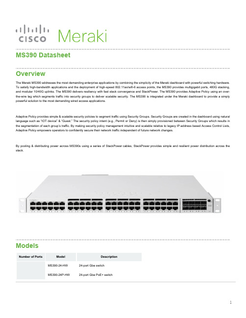
MS390 DatasheetOverviewThe Meraki MS390addresses the most demanding enterprise applications by combining the simplicity of the Meraki dashboard with powerful switching hardware. To satisfy high-bandwidth applications and the deployment of high-speed802.11ax/wifi-6access points,the MS390provides multigigabit ports,480G stacking, and modular10/40G uplinks.The MS390delivers resiliency with fast stack convergence and StackPower.The MS390provides Adaptive Policy using an over-the-wire tag which segments traffic into security groups to deliver scalable security.The MS390is integrated under the Meraki dashboard to provide a simply powerful solution to the most demanding wired access applications.Adaptive Policy provides simple&scalable security policies to segment traffic using Security Groups.Security Groups are created in the dashboard using natural language such as“IOT device”&“Guest.”The security policy intent(e.g.,Permit or Deny)is then simply provisioned between Security Groups which results in the segmentation of each group’s traffic.By making security policy management intuitive and scalable relative to legacy IP-address based Access Control Lists, Adaptive Policy empowers operators to confidently secure their network traffic independent of future network changes.By pooling&distributing power across MS390s using a series of StackPower cables,StackPower provides simple and resilient power distribution across the stack.ModelsNumber of Ports Model DescriptionMS390-24-HW24-port Gbe switchMS390-24P-HW24-port Gbe PoE+ switch24 Ports MS390-24U-HW24-port Gbe UPoE switch MS390-24UX-HW24-port mGbe UPoE switch48 Ports MS390-48-HW48-port Gbe switchMS390-48P-HW48-port Gbe PoE+ switchMS390-48U-HW48-port Gbe UPoE switchMS390-48UX-HW36-port 2.5Gbe + 12-port mGbe UPoE switch MS390-48UX2-HW48-port 5Gbe UPOE switchFeaturesCategory FeaturesHighlights •Layer-3•40G or 10G modular uplink options on all models •mGig support•Dual Dedicated 120G Hardware Stacking Ports •PoE+ and UPoE Support•StackPowerManagement •Managed via Cisco Meraki Dashboard•Zero-touch remote provisioning (no staging needed)•Basic configuration capability via local management page•Detailed historical per-port and per-client usage statistics•Operating System, device, and hostname fingerprinting•Automatic firmware upgrades with scheduling control•SNMP and SYSLOG support for integration with other network management solutions*Remote Diagnostics •Email, SMS and Mobile push notification alerts1•Ping, traceroute, cable testing, and link failure detection with alerting •Remote packet capture•Dynamic and interactive network discovery and topology •Combined event and configuration change logs with instant searchStacking •Physically stack up to 8 switches with 480 Gbps of stacking bandwidth on all models•Virtual stacking supports thousands of switch ports in a single logical stack for unified management, monitoring, and configuration•Faster convergence•StackPowerEthernet Switching Capabilities •802.1p Quality of Service, 8 queues (w/ 6 configurable for DSCP-to-CoS mapping)•802.1Q VLAN and trunking support for up to 4,094 VLANs (1000 active VLANs with STP enabled)•Single Instance of 802.1s Multiple Spanning Tree Protocol (interoperable with RSTP, STP, PVST, RPVST)•STP Enhancements: BPDU guard, Root guard, Loop guard, UDLD•Broadcast storm control•802.1ab Link Layer Discovery Protocol (LLDP) and Cisco Discovery Protocol (CDP)•802.3ad Link aggregation with up to 8 ports per aggregate, Multichassis aggregates supported on stacked switches •Port mirroring•IGMP snooping for multicast filtering•MAC Forwarding Entries: 32KLayer 3•Static routing, OSFPv2•Multicast routing (PIM-ASM)•Warm Spare (VRRP)•DHCP Server, DHCP RelaySecurity •Integrated multi-factor authentication for Dashboard management•Role-based access control (RBAC) with granular device and configuration control •Corporate wide password policy enforcement•IEEE 802.1X RADIUS and MAB, hybrid authentication and RADIUS server testing •Single-Host/Multi-Domain/Multi-Host/Multi Authentication•Port security: Sticky MAC, MAC whitelisting•DHCP snooping, detection and blocking, Dynamic ARP Inspection•IPv4 and IPv6 ACLs•Secure Connect *•Adaptive Policy *MS390 LicensingMS390license structure includes two feature tiers:Enterprise and Advanced. The MS390 also introduces a new and simpler license to hardware mapping, specifically 24-port or 48-port licenses. As with all MS, every MS390 license is available in 1, 3, 5, 7, and 10 year terms.MS390 License Structure24-Port Model48-port ModelAdvanced Features LIC-MS390-24A LIC-MS390-48A* Available in a future software releaseEnterprise Features LIC-MS390-24E LIC-MS390-48EThe features available with advanced licensing are:•Adaptive policy *•Greater than 1,000 routes for OSPF* Available in a future software releaseContext and Comparisons24 Port Models48 Port ModelsDescription MS350-24X MS355-24X2MS390-24UX MS350-48FP MS355-48X2MS390-48UX2 1GbE RJ4516--4824-mGbE RJ4582424-244810GbE SFP+44Modular44Modular40GbE QSFP+n/a2Modular-2Modular Hardware Stack Port2x 40G2x 100G2x 120G2x 40G2x 100G2x 120G Management Interface111111Hot Swap PS Yes, Dual Yes, Dual Yes, Dual Yes, Dual Yes, Dual Yes, Dual Hot Swap Fans Yes, 2x Yes, 3x Yes, 3x Yes, 2x Yes, 3x Yes, 3x Layer 3 Routing Yes Yes Yes Yes Yes Yes UPoE Capable Yes, 740W Yes, 740W Yes, 560W Yes, 740W Yes, 740W Yes, 645W Max Switching Capacity176 Gbps640 Gbps640 Gbps176 Gbps688 Gbps640 Gbp Max Stacking Bandwidth160 Gbps400 Gbps480 Gbps160 Gbps400 Gbps480 GbpsTechnical BreakdownInterfaces SpecificationsModel InterfacesUplink10/40GbE(SFP+, QSFP+)120G Hardware Stack PortDedicated ManagementInterfacePoE/UPoECapabilitiesMS390-24-HW24 x1GbE RJ45Modular21n/aMS390-24P-HW24 x1GbE RJ45Modular21PoEMS390-24U-HW24 x1GbE RJ45Modular21UPoEMS390-24UX-HW24 x mGbE RJ45Modular21UPoEMS390-48-HW48 x1GbE RJ45Modular21n/aMS390-48P-HW48 x1GbE RJ45Modular21PoEMS390-48U-HW48 x1GbE RJ45Modular21UPoEMS390-48UX-HW36 x100M/1G/2.5G +12 x100M/1G/2.5G/5G/10GModular21UPoEMS390-48UX2-HW48 x100M/1G/2.5G/5G Modular21UPoEPhysical SpecificationsModelDimensions(h x w x d)W/ Default Power SupplyWeight Mount Type Hot Swap Fans Operating Temperature Humidity MS390-24-HW1.73” x 17.5” x17.7”(4.4 x 44.5 x 44.9cm)16.03 lb (7.27 kg)1U Rack Mount Yes, 3x-5°C to 45°C 5 to 90%MS390-24P-HW1.73” x 17.5” x17.7”(4.4 x 44.5 x 44.9cm)16.33 lb (7.4 kg)1U Rack Mount Yes, 3x-5°C to 45°C 5 to 90%All models are available with modular uplinks that have been listed under the Accessories list. For supported SFP modules please refer the SFP Datasheet.1.73” x 17.5” x 19.2”MS390-24U-HW16.63 lb (7.54 kg)1U Rack Mount Yes, 3x-5°C to 45°C 5 to 90%(4.4 x 44.5 x 44.8cm)1.73” x 17.5” x 20.2”18.18 lb (8.25 kg)1U Rack Mount Yes, 3x-5°C to 45°C 5 to 90% MS390-24UX-HW(4.4 x 44.5 x 51.3cm)1.73” x 17.5” x17.7”16.43 lb (7.45 kg)1U Rack Mount Yes, 3x-5°C to 45°C 5 to 90% MS390-48-HW(4.4 x 44.5 x 44.9cm)1.73” x 17.5” x17.7”MS390-48P-HW16.73 lb (7.59 kg)1U Rack Mount Yes, 3x-5°C to 45°C 5 to 90%(4.4 x 44.5 x 44.9cm)1.73” x 17.5” x 19.2”17.03 lb (7.72 kg)1U Rack Mount Yes, 3x-5°C to 45°C 5 to 90% MS390-48U-HW(4.4 x 44.5 x 48.8cm)1.73” x 17.5” x 22.2”MS390-48UX-HW20.50 lb (9.34 kg)1U Rack Mount Yes, 3x-5°C to 45°C 5 to 90%(4.4 x 44.5 x 56.4cm)1.73” x 17.5” x 22.2”MS390-48UX2-HW20.05 lb (9.09 kg)1U Rack Mount Yes, 3x-5°C to 45°C 5 to 90%(4.4 x 44.5 x 56.4cm)PerformanceSwitching Capacity Stacking Bandwidth Forwarding rateModelMS390-24-HW208 Gbps480 Gbps154.76 MppsMS390-24P-HW208 Gbps480 Gbps154.76 MppsMS390-24U-HW208 Gbps480 Gbps154.76 MppsMS390-24UX-HW640 Gbps480 Gbps476.19 MppsMS390-48-HW256 Gbps480 Gbps190.48 MppsMS390-48P-HW256 Gbps480 Gbps190.48 MppsMS390-48U-HW256 Gbps480 Gbps190.48 MppsMS390-48UX-HW580 Gbps480 Gbps431.54 MppsMS390-48UX2-HW 640 Gbps 480 Gbps 476.19 MppsPower Options and SpecificationsModelDefault PowerSupplyHot Swap PowerSupplyAvailable PoE W/Primary PSAvailable PoE W/ SecondaryPS***Power Load (idle/max)MS390-24-HW MA-PWR-350WAC**Yes, Dual n/a n/a 79.2 / 99 WMS390-24P-HW MA-PWR-715WAC**Yes, Dual 445W 720W84.1 / 554.4W MS390-24U-HW MA-PWR-1100WAC Yes, Dual 830W 1440W85.4 / 990.3W MS390-24UX-HW MA-PWR-1100WAC Yes, Dual 560W 1440W162.7 / 809.9W MS390-48-HW MA-PWR-350WAC**Yes, Dual n/a n/a83.9 / 109.9WMS390-48P-HW MA-PWR-715WAC**Yes, Dual 437W 1152W 92.6 / 555 WMS390-48U-HW MA-PWR-1100WAC Yes, Dual 822W 1800W145 / 844.9W MS390-48UX-HW MA-PWR-1100WAC Yes, Dual 490W 1590W218.5 / 785.5W MS390-48UX2-HW MA-PWR-1100WACYes, Dual 645W 1745W157.9 / 843.8WWhat's includedModel Package ContentsMS390-24-HW 1 x Power Supply (MA-PWR-350WAC), Rack mount brackets and screw kit,3 x Pre-Installed Fans, Cable guide MS390-24P-HW1 x Power Supply (MA-PWR-715WAC), Rack mount brackets and screw kit, 3 x Pre-Installed Fans, Cable guide** Upgrade options to 715W and 1100W PSU are available.*** The PoE values are provided considering the secondary PS to be the default power supply of the respective model.MS390-24U-HW 1 x Power Supply (MA-PWR-1100WAC), Rack mount brackets and screw kit, 3 x Pre-Installed Fans, Cable guideMS390-24UX-HW 1 x Power Supply (MA-PWR-1100WAC), Rack mount brackets and screw kit, 3 x Pre-Installed Fans, Cable guideMS390-48-HW 1 x Power Supply (MA-PWR-350WAC), Rack mount brackets and screw kit, 3 x Pre-Installed Fans, Cable guideMS390-48P-HW 1 x Power Supply (MA-PWR-715WAC), Rack mount brackets and screw kit, 3 x Pre-Installed Fans, Cable guideMS390-48U-HW 1 x Power Supply (MA-PWR-1100WAC), Rack mount brackets and screw kit, 3 x Pre-Installed Fans, Cable guideMS390-48UX-HW 1 x Power Supply (MA-PWR-1100WAC), Rack mount brackets and screw kit, 3 x Pre-Installed Fans, Cable guideMS390-48UX2-HW 1 x Power Supply (MA-PWR-1100WAC), Rack mount brackets and screw kit, 3 x Pre-Installed Fans, Cable guideOptional AccessoriesAccessory Description Supported ModelsMA-PWR-350WAC350W AC Power Supply MS390-24-HW, MS390-48-HWMA-PWR-715WAC715W AC Power Supply All ModelsMA-PWR-1100WAC1100W AC Power Supply All ModelsMA-MOD-2X40G 2 x 40G Uplink Module All ModelsMA-MOD-4X10G 4 x 10G Uplink Module All ModelsMA-MOD-8X10G8 x 10G Uplink Module All ModelsMA-CBL-120G-50CM Meraki 120G Stacking Cable, 0.5Meter All ModelsMA-CBL-120G-1M Meraki 120G Stacking Cable, 1Meter All ModelsMA-CBL-120G-3M Meraki 120G Stacking Cable, 3Meter All ModelsMA-CBL-SPWR-30CM Meraki MS390 30CM Power-Stack Cable All ModelsMA-CBL-SPWR-150CM Meraki MS390 150CM Power-Stack Cable All ModelsMA-FAN-16K2System Fan All ModelsMA-RCKMNT Meraki MS390 Rack Mount Kit All ModelsRegulations and ComplianceElectromagnetic FCC Part 15 (CFR 47) Class A, ICES-003 Class A, CISPR22 Class A,CNS13438, EN 300 386 V1.6.1,EN 55022 Class A, ENCompatibility Certifications 61000-3-2,EN61000-3-3, KN 32, TCVN 7189 Class A, EN 55032 , CISPR 32 Class A, V-2/2015.04, V-3/2015.04, VCCI-CISPR 32 Class A, CISPR24, EN 300 386 V1.6.1, EN 55024, KN35, TCVN 7317SafetyCAN/CSA-C22.2 No. 60950-1, UL 60950-1, EN 60950-1, IEC 60950-1, AS/NZS 60950.1 Environmental Reduction of Hazardous Substances (RoHS)Warranty Full lifetime hardware warranty with next-day advanced replacement includedMTBF RatingModelMTBF at 25°CMS390-24-HW314,790MS390-24P-HW299,000MS390-24U-HW238,410MS390-24UX-HW214,760MS390-48-HW305,870MS390-48P-HW277,770MS390-48U-HW227,410MS390-48UX-HW202,160MS390-48UX2-HW198,647Installation GuideFor instructions on how to install and configure the MS390 series switch please refer the MS390 Series Installation Guide。
Fiber Distribution Frame Cable Clamp Kit (E-501-L4
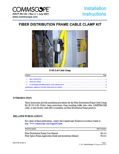
ADCP-90-123 Rev C Page 1. © 2021 CommScope.All Rights Reserved.E-501-L40 Cable Clamp1KIT CONTENTS . . . . . . . . . . . . . . . . . . . . . . . . . . . . . . . . . . . . . . . . . . . . . . . . . . . . . . . . . . . . . . . . . . . . . . . . . . . . . . . . . . 22INSTALLATION . . . . . . . . . . . . . . . . . . . . . . . . . . . . . . . . . . . . . . . . . . . . . . . . . . . . . . . . . . . . . . . . . . . . . . . . . . . . . . . . . . 33CUSTOMER INFORMATION AND ASSISTANCE . . . . . . . . . . . . . . . . . . . . . . . . . . . . . . . . . . . . . . . . . . . . . . . . . . . . . 8APPENDIX: SHIELD CONNECTOR INSTALLATION . . . . . . . . . . . . . . . . . . . . . . . . . . . . . . . . . . . . . . . . . . . . . . . . . . . . . . . 9INTRODUCTIONThese instructions provide installation procedures for the Fiber Distribution Frame Cable Clamp Kit (E-501-L40). Follow these instructions when installing buffer tube cable, LIGHTPACK® cable, or intra facility cable (IFC) assemblies on Fiber Distribution Frame products.RELATED PUBLICATIONSFor copies of these publications, contact the CommScope Technical Assistance Center at /SupportCenterFiber Distribution Frame User Manual90-113Fiber Splice Frame Application Guide and Installation Manual 90-321Content PageTitle/DescriptionADCP NumberADCP-90-123 • Rev C • July FIBER DISTRIBUTION FRAME CABLE CLAMP KITInstallation InstructionsADCP-90-123 • Rev C • July 2021Trademark InformationCommScope (logo) and Commscope are registered trademarks of CommScope, Inc.LIGHTPACK® is a registered trademark of NS-MPG, Inc.ScotchLok® is a registered trademark of 3M.1KIT CONTENTSThe E-501-L40 cable clamp kit provides the necessary hardware for securing the cable end tothe frame and for connecting metallic strength members or metallic cable sheaths to the frameground conductor. Each kit contains the components listed in Table 1.Table 1. E-501-L40 Component ListQUANTITY DESCRIPTION1Clamp bracket1Clamp cover2Cable yoke1Inner grommet, .40 diameter1Inner grommet, .50 diameter1Inner grommet, .60 diameter1Inner grommet, .70 diameter1Outer grommet, .80 diameter1Outer grommet, .90 diameter1Outer grommet, 1.00 diameter1Outer grommet, 1.10 diameter8Cable ties26-32 × .25 inch screw210-32 × 2.0 inch screw210-32 nut1Shield connector1Split bolt1Ground wire assembly1Instruction sheet3Large cable ties1Plastic edge protector1Installation drawingPage 2© 2021 CommScope, Inc. All Rights ReservedADCP-90-123 • Rev C • July 2021Page 3© 2021 CommScope, Inc. All Rights Reserved2INSTALLATIONThis section describes how to secure outside plant or IFC assemblies to the Fiber Distribution Frame using the cable clamp kit. The E-501-L40 clamp kit will accommodate cable that has an external diameter of 0.40 inch to 1.20 inches (10.2 - 30.5 mm). Cable may be routed to each clamping location from either the top or the bottom of the frame and may be clamped to either the left or right side of the frame. Use the following procedure to route and clamp each cable.1.Route the cable to the selected cable clamping position at the rear of the frame.2.Determine the length of the service loop required for routing the fibers from the clamppoint on the frame to the actual cable termination point. If installing OSP cables, refer to the Fiber Distribution Frame User Manual (ADCP-90-113) or Fiber Splice Frame Application Guide and User Manual (ADCP-90-191) for the routing procedure and the stripping recommendations. If installing IFC assemblies, refer to the Intra facility Fiber Cable Kit Instruction Sheet (ADCP-90-165) for the routing procedure and the fiber breakout lengths3.Strip back the cable sheath and prepare the cable fibers as required for installation.Outside plant cables are generally routed to a splice module for splicing to pigtails.If LIGHTPACK cable is installed, a buffer tube kit (accessory item) is required toIf the cable is filled with water blocking compound, the cable end must be sealed toInstall kit according to instructions provided with the kit.If the cable has a metallic sheath, a special connector is provided for grounding the ® 4460 Shield Connectors manufactured by 3M.ADCP-90-123 • Rev C • July 2021Page 44.Secure the clamp bracket to the Fiber Distribution Frame cable plate as shown in Figure 1.The bottom of the bracket (end with slots) should be angled toward the fanning triangles.Figure 1. Installing Clamp Bracket5.Two rubber yokes and eight grommets of various sizes are provided for securing the cable.Determine the correct grommet(s) to use by separating the grommets into two groups as shown in Figure 2. Place the four small grommets in the first group. Place the four large grommets in the second group.6.Determine the outside diameter of the cable. If the cable diameter is 0.4 inch or greater,but less than 0.8 inch, proceed to step 7. If the cable diameter is 0.8 inch or larger, proceed to step 8.7.If the cable diameter is 0.4 inch or greater, but less than 0.8-inch, place all four of the 0.8inch OD grommets around the cable. Look at each grommet, then select the one with a gap that is approximately zero to 0.030-inch (7.6 mm) wide. Also, select the 1.2 inch OD grommet with the thickest side walls.8.If the cable diameter is greater than 0.8 inch but less than 1.1 inches, place all four of the1.2-inch OD grommets around the cable. Look at each grommet, then select the one with agap that is approximately zero to 0.030-inch (7.6 mm) wide.If the cable diameter is larger than 1.1 inch, no grommet is required.INSTALL 10-32 SCREW IN CLAMPBRACKET BEFORE MOUNTINGBRACKET ON CABLE PLATEADCP-90-123 • Rev C • July 2021Page 5© 2021 CommScope, Inc. All Rights ReservedFigure 2. Rubber GrommetsGROMMETS WITH 1.2 INCH OUTSIDE DIAMETERGROMMETS WITH 0.8 INCH OUTSIDE DIAMETERWHENEVER A SMALL GROMMET (FROM THE LEFT COLUMN OF GROMMETS) IS USED,THIS GROMMET MUST BE PLACED AROUND IT 2489-BADCP-90-123 • Rev C • July 2021Page 6© 2021 CommScope, Inc. All Rights Reserved9.Place the rubber yokes and grommets (as required) around the cable and secure cable toclamp bracket as shown in Figure 3.Figure 3. Installed Cablee the small cable ties to secure the cable fibers to the end of the clamp e the large cable ties to secure the cable to the side of the frame. Use the tie bars that aremounted on the sides of the rack as attachment points.If the cable diameter is larger than 1.1 inch, no grommet is required.10-32 SCREW(2)3314-BADCP-90-123 • Rev C • July 2021Page 7© 2021 CommScope, Inc. All Rights Reserved12.If cable must be grounded, use the split-bolt connector to secure the metallic strengthmember or ground wire assembly to the frame ground conductor as shown in Figure 4.Figure 4. Installed Cable27466-ASPLIT BOLT CONNECTORMETALLIC STRENGTHMEMBER FROM CABLELOOSE BUFFERTUBESADCP-90-123 • Rev C • July 20213CUSTOMER INFORMATION AND ASSISTANCE For product support, use the following URL:http://www,/SupportCenterFor information on patents, refer to:http://www,Page 8© 2021 CommScope, Inc. All Rights ReservedADCP-90-123 • Rev C • July 2021Page 9Reproduced by permission of 3M Company, from 3M Instruction Bulletin, Issue 1, dated February 1985, Number 43-7018-2209-9APPENDIX: SHIELD CONNECTOR INSTALLATIONThis Appendix provides the procedures for installing Scotchlok 4460 Shield Connectors which are manufactured by the 3M Company and utilized in the Fiber Management Panel. The shield connector kit provides a means for grounding cables that have a metallic shield. Use the following procedure to install each kit:1.The shield connector kit is comprised of the components shown in Figure A-1.Figure A-1. Kit Components2.Prepare the cable by cutting the shield flush with the outer cable sheath as shown in FigureA-2. If the cable has a double sheath, cut only the outer sheath and shield leaving the inner sheath intact as shown.Figure A-2. Cable Preparation2 SECURING NUTSTOPBASE27471-ACABLE SINGLE SHEATH CABLEDOUBLE SHEATH CABLEOUTER WRAP27470-AADCP-90-123 • Rev C • July 2021Page 10Reproduced by permission of 3M Company, from 3M Instruction Bulletin, Issue 1, dated February 1985, Number 43-7018-2209-93.Make a one-inch cut in the cable sheath opposite the point at which the connector will beattached as shown in Figure A-3.Figure A-3. Cutting Cable Sheath4.If installing single shield cable, insert connector base between shield and core wrap. Ifinstalling double shield cable, insert connector base between shield and inner sheath.5.Slide connector into cable until stops contact outer sheath. Tap on shield above connectorat point shown in Figure A-4 to set teeth.Figure A-4. Setting Connector Teeth6.Install bonding wire on stud and place connector top over bonding wire. Do not tap onconnector top.7.Install both nuts on connector as shown in Figure A-5 and tighten.Figure A-5. Bonding Wire Installation1.0 IN. (25 mm)27469-ATAP HERE。
艾莫ン电压较低功率电路保护器MPSC404MEAXX2Q说明书
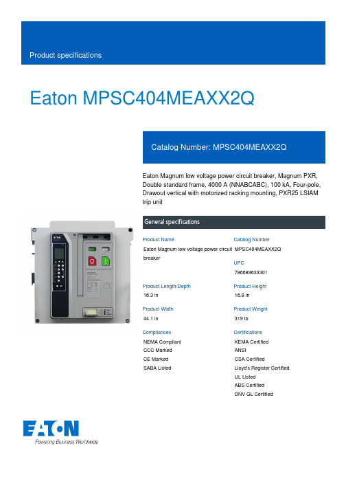
Eaton MPSC404MEAXX2QEaton Magnum low voltage power circuit breaker, Magnum PXR,Double standard frame, 4000 A (NNABCABC), 100 kA, Four-pole,Drawout vertical with motorized racking mounting, PXR25 LSIAMtrip unitGeneral specificationsEaton Magnum low voltage power circuitbreakerMPSC404MEAXX2Q78668963330116.3 in16.8 in44.1 in319 lbNEMA Compliant CCC MarkedCE Marked SABA Listed KEMA CertifiedANSICSA CertifiedLloyd's Register Certified UL ListedABS CertifiedDNV GL CertifiedProduct Name Catalog NumberUPCProduct Length/Depth Product Height Product Width Product Weight Compliances CertificationsDouble standard Four-pole Magnum PXRDouble standard Magnum PXR25 LSI ARMSFour-pole4000 A100 kAIC100 kAIC4000 AZone selective interlocking application paper Magnum circuit breakers with Power Xpert Release trip units product aid Selevctive coordination application paper - IA0120000E3Magnum PXR and PD-SB standard and narrow frame UL Certificate of ComplianceMagnum PXR and PD-SB double and double narrow frame UL Certificate of ComplianceMagnum PXR low voltage power circuit breakers user manual Microsoft Word - Power Xpert Protection Manager Quick Start Guide.docxFrameNumber of poles TypeFrameSeries Trip TypeNumber of poles Rated uninterrupted current (Iu)Interrupt rating Interrupt rating Rated uninterrupted current (Iu)Application notesBrochuresCatalogsCertification reportsManuals and user guidesEaton Corporation plc Eaton House30 Pembroke Road Dublin 4, Ireland © 2023 Eaton. All Rights Reserved. Eaton is a registered trademark.All other trademarks areproperty of their respectiveowners./socialmediaPower Xpert Release trip unit for Magnum PXR circuit breakers PXR 20/25 user manualPower Xpert Protection Manager x64 22.6 1 Power Xpert Protection Manager x32 22.06 1 Eaton Specification Sheet - MPSC404MEAXX2Q Low voltage circuit breakers guide spec Magnum PXR 20/25 electronic trip units time current curves Molded case and low-voltage power circuit breaker health Cyber security white paperSafer by design: arc energy reduction techniquesSoftware, firmware, and applications Specifications and datasheetsTime/current curvesWhite papers。
永磁磁滞回线测量仪Permagraph L(1)

Page 6 / 12
曲线
退磁曲线 完整磁滞回线 回复线 可在 HcJ 点自动停止 可在 -Imax 点自动停止 (BH)max 区域 B=0 曲线
评估
剩磁(Br 或 Jr) J 曲线矫顽力 HcJ(内禀矫顽力) B 曲线矫顽力 HcB(矫顽力) 最大磁能积(BH)max 最大磁场强度 Hk: 肘型参数(当 B = 0.9 ·Br 时,H 等同于内禀曲线) Hx: 当 B = x ·Br 时,H 等同于 J(H) 曲线 (H) and B(H) 列表, 此处 H 为客户定义的磁场强度. 可以预先设定和存储 H 值列表. 样品、测量参数和计算结果的输出到 ASCII 文件,便于导入其他程序进行处理 样品、测量参数和计算结果输出到数据库内 温度校正:根据温度系数对结果进行转化
标准配置
配置 2 Permagraph L (仅用于在室温条件下测量) 1 个 PERMAGRAPH L 电器柜,配有用于测量、 电子控制以及加热极头的电源 ® 1 个 PERMAGRAPH 电源 SVP 2 1 个测量和控制单元 ST-P-L 1 个电磁铁 EP 3 2 个极头 P 0/0, 直径 Ø92 mm 1 个室温条件下使用的 J 补偿环绕线圈 JH 26-1 (其他线圈直径可选) 1 台电脑 1 套在 Windows 系统下运行的操作软件 PERMA 1 天培训
单位
软件和输出完全支持 SI 和 CGS 单位制 可随时进行单位制转换 图标上同时显示 SI 和 CGS 两种单位
控制单元 ® 标准型 Permagraph L 的计算机硬件 为了设置该自动测量系统并保证上述软件顺利安装,需要的电脑硬件配置如下: 电脑 硬盘驱动 CD/DVD 驱动 网络连接 LCD 显示器 键盘, 鼠标 接口 (COM, USB) 打印机,电脑等等的连接线. WINDOWS (最新版本) HP 台式打印机 (当前型号)
- 1、下载文档前请自行甄别文档内容的完整性,平台不提供额外的编辑、内容补充、找答案等附加服务。
- 2、"仅部分预览"的文档,不可在线预览部分如存在完整性等问题,可反馈申请退款(可完整预览的文档不适用该条件!)。
- 3、如文档侵犯您的权益,请联系客服反馈,我们会尽快为您处理(人工客服工作时间:9:00-18:30)。
P/ACTIVE EMI/RFI T FILTER
Features
•8 Filter Channels in Miniature QSOP Package •Ideal Frequency Response to Over 3 GHz •Low In-Band Insertion Loss Maintains Signal Integrity
•Low Distortion Low Cross Talk •ESD Protected
Applications
•EMI/RFI Filter •Low Pass Filter •SCSI Port Filter
•LCD Panel Display Filter
Product Description
Note: CAMD’s P/Active T Filter is a higher performance, upgraded version of the original PRC200/210 series which provides 2KV ESD
protection, minimized lead inductance and parasitic capacitive effects (with added ground pins), and improved crosstalk and filter performance characteristics at high data transmission rates. They exhibit almost ideal RC characteristics to 3 GHz. The P ACT series is recommended for all new designs.
CAMD’s P/Active T is a highly integrated thin film resistor-capacitor network designed to suppress EMI/RFI noise at I/O ports of personal computers and peripherals, workstations, Local Area Network (LAN), Asynchronous Transfer Mode (ATM), and Wide Area Network (WAN). The filter includes ESD protection circuitry which prevents device
destruction when subjected to ESD discharges of greater than 2KV . The ESD protection circuitry permits the filter to operate on bipolar signals of up to ±6V. CAMD’s PACT is housed in a surface mount package suitable for bottom side mounting to the board. This integrated network solution minimizes space and routing problems and improves reliability and yields.
Why P/Active EMI/RFI filters? EMI/RFI filters are needed to suppress noise at low and high frequencies of the signal.Ferrite beads, commonly used for EMI/RFI filtering, are bulky and ineffective at low frequencies and have saturation problems at high frequencies. Resistor-capacitor networks offer the best technical approach for effective EMI/RFI filtering. Also, conventional thick film-based EMI/RFI filters do not effectively suppress noise at high frequencies.
Pin Assignments
123456789101112
242322212019181716151413
GND Filt1Filt2Filt3GND Filt4Filt5GND Filt6Filt7Filt8GND
GND Filt1Filt2Filt3GND Filt4Filt5GND Filt6Filt7Filt8GND
Filter Insertion Loss (S12, dB), Typical (T A = 25o C)Representative Sample
ATTENUATION CURVES
S parameters are measured using a Hewlett Packard HP8753C Network Analyzer with a HP85047A S-parameter Test Set.。
