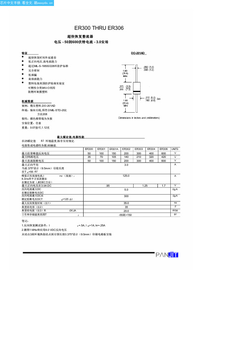
ER2003CT中文资料(PANJIT)中文数据手册「EasyDatasheet - 矽搜」
2003年7月LVDT卡片指南书说明书

Safety GuidelinesWarning notices must be observed to ensure personal safety as well as that of others, and to protect the product and the connected equipment. These warning notices are accompanied by a clarification of the level of caution to be observed.Qualified PersonnelThis device/system may only be set up and operated in conjunction with this manual. Qualified personnel are only authorized to install and operate this equipment in accordance with established safety practices and standards.Warning:This product can only function properly and safely if it is correctly transported, stored, installed, set up, operated, and maintained.Note: Always use product in accordance with specifications.This document is available in bound version and inelectronic version. We encourage users to purchase authorized bound manuals, or to viewelectronic versions as designed and authored bySiemens Milltronics Process Instruments Inc. Siemens Milltronics Process Instruments Inc. will not be responsible for the contents of partial or whole reproductions of either bound or electronic versions.While we have verified the contents ofthis manual for agreement with the instrumentation described, variationsremain possible. Thus we cannotguarantee full agreement. The contents of this manual are regularly reviewed and corrections are included in subsequent editions. We welcome all suggestions for improvement. Technical data subject to change.MILLTRONICS®is a registered trademark of Siemens Milltronics Process Instruments Inc. Contact SMPI Technical Publications at the following address:Technical PublicationsSiemens Milltronics Process Instruments Inc.1954 Technology Drive, P.O. Box 4225Peterborough, Ontario, Canada, K9J 7B1Email: techpubs@SpecificationsPower:•±5 V dc (typically from a Milltronics integrator)Ambient Temperature:•-40 to 50 o C (-40 to 122 o F)Input:•0 to 1.0 Vac from LVDT based belt scale or solids flow meter (maximum 3m [(10 ft]separation between LVDT and Conditioner Card).Output:•0 to 50m Vdc to Milltronics BW100 or BW500/SF500(maximum 300 m (1000 ft) separation between Conditioner Card and Integrator).•Accuracy: 0.1% of rangeEnclosure:•General Purpose Type 4/Nema 4Approvals:•CECable:•LVDT Conditioner Card to Integrator: Belden 8404, 4 conductor, shielded 20 AWG orequivalent, 150m (500 ft) max.Belden 9260, 6 conductor, shielded 20 AWG or equivalent, 300 m (1000 ft) max.•LVDT to LVDT Conditioner Card (CT connection not required): Belden 8404, 4 conductor, shielded 20 AWG or equivalent, 300 m (1000 ft) max.7ML19985EF01LVDT Conditioner Card– INSTRUCTION MANUAL Page 1The LVDT Conditioner CardThe LVDT (Linear Variable Differential Transformer) Conditioner Card is an ancillary piece of equipment. The LVDT Conditioner Card provides all the complex circuitry required to allow the Milltronics BW100 or BW500 to interface with a position transducer (LVDT) based scale.It also allows the SF500 to interface with a position transducer (LVDT) based solidsflowmeter.General OperationThe Milltronics BW100 or BW500/SF500 supplies the excitation for the LVDT Conditioner Card, which in turn supplies the excitation for the LVDT.In belt scale operations the LVDT signal is proportional to material loading. The LVDT signal is converted to a 0-50mVdc signal then applied to the Load Cell A input of theMilltronics BW100 or BW 500 and used with the speed signal to produce an integral rate signal.In solids flowmeter applications, the LVDT signal is proportional to the material flow rate.The LVDT signal is converted to a 0-50mV dc signal then applied to Load Cell A input of the Milltronics SF500 and used to produce an integral rate signal. InterconnectionPage 2 LVDT Conditioner Card – INSTRUCTION MANUAL7ML19985EF01Connection to a BW500/SF500* Where separation between the integrator and LVDT conditioner exceeds 150 m (500 ft):•remove the jumpers BW500/SF500 terminal 11/12 and 13/14, or BW100 terminal 17/18 and 19/20•run additional conductors from:BW500/SF500 terminal 12, or Milltronics BW100 terminal 19, to conditioner terminalblock marked Integrator +EXCBW500/SF500 terminal 13, or Milltronics BW100 terminal 18, to conditioner terminalblock marked Integrator -EXCFor further connection information on specific LVDTs, consult Siemens Milltronics. See for a representative near you.!Shields are common, but not grounded to chassis. Run cable shields through SHLD terminals and ground at integrator only.The LVDT Conditioner Card is also available in a smaller configuration for mounting within the solids flowmeter sensing head.7ML19985EF01LVDT Conditioner Card– INSTRUCTION MANUAL Page 3InstallationTop ViewPage 4 LVDT Conditioner Card – INSTRUCTION MANUAL7ML19985EF01。
ER306中文资料(Pan Jit)中文数据手册「EasyDatasheet - 矽搜」
最大经常峰值反向电压
最大RMS电压
最大直流阻断电压
最大正向平均
当前.375"设计(9.5mm)引线长度
在T A=55 ¢J
峰值正向浪涌电流,I 8.3ms单半正弦波叠加
FM (浪涌):
在额定负荷(JEDEC方法)
最大正向电压在3.0A DC
反向电流最大DC 在额定阻断电压DC 反向电流最大DC在 额定阻断电压DCT
0.1
TJ = 25 ¢J PULSE WIDTH = 300uS
2% DUTY CYCLE 0.01
0.4 0.6 0.8 1.0 1.2 1.4 1.6 1.8
正向电压,伏
图. 4正向电流降额曲线
100
TJ = 25 ¢J
f = 1.0MHz
Vsig = 50mVp-p
50 100
结电容,P1F0
4.0
3.0
(10)-A2M.0P (10)-AAV
.375" 9.5mm LENGTH
平均正向电1.0流
0 50 75 100 125 150 175 200
环境温度,
¢J
图. 2,最大正向平均
电流额定值
100 ER300 ~ ER302
ER303 ~ ER304 10
安培
1
瞬时正向电流,
ER306
可燃性分类94V-O利用
阻燃环氧模塑料
DO-201AD
机械数据
案例:模压塑料,DO-201AD 终端:轴向引线,焊符合MIL-STD-202,
方法208
极性:颜色频带端为负极 安装位置:额定值 ,电器性能 在25额定值 ¢J 环境温度,除非另有规定.
电阻性或电感性负载,60赫兹.
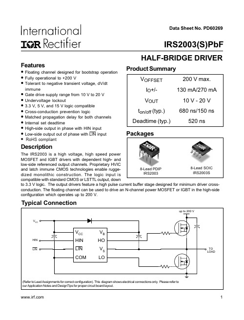
IRS2003STRPbF中文资料
Data Sheet No. PD60269Typical ConnectionProduct SummaryV OFFSET 200 V max.I O +/-130 mA/270 mA V OUT 10 V - 20 V t on/off (typ.)680 ns/150 nsDeadtime (typ.)520 nsHALF-BRIDGE DRIVERFeatures•Floating channel designed for bootstrap operation •Fully operational to +200 V•Tolerant to negative transient voltage, dV/dtimmune•Gate drive supply range from 10 V to 20 V •Undervoltage lockout•3.3 V, 5 V, and 15 V logic compatible •Cross-conduction prevention logic•Matched propagation delay for both channels •Internal set deadtime•High -side output in phase with HIN input •Low -side output out of phase with LIN input DescriptionThe IRS2003 is a high voltage, high speed power MOSFE T and IGBT drivers wi th dependent high - and low -side referenced output channels. Proprietary HVICand latch immune CMOS technologies enable rugge-dized monolithic construction. The logic input iscompatible with standard CMOS or LSTTL output, downto 3.3 V logic. The output drivers feature a high pulse current buffer stage designed for minimum driver cross-conduction. The floating channel can be used to drive an N-channel power MOSFET or IGBT in the high -side configuration which operates up to 200 V. 1IRS2003(S)PbFPackages8-Lead PDIP IRS20038-Lead SOIC IRS2003S • RoHS compliantIRS2003(S)PbFAbsolute Maximum RatingsAbsolute maximum ratings indicate sustained limits beyond which damage to the device may occur. All voltage param-eters are absolute voltages referenced to COM. The thermal resistance and power dissipation ratings are measured under board mounted and still air conditions.Note 1: Logic operational for V S of -5 V to +200 V. Logic state held for V S of -5 V to -V BS . (Please refer to the Design Tip DT97-3 for more details).IRS2003(S)PbFStatic Electrical CharacteristicsV BIAS (V CC, V BS) = 15 V and T A = 25 °C unless otherwise specified. The V IN, V TH, and I IN parameters are referenced to COM. The V O and I O parameters are referenced to COM and are applicable to the respective output leads: HO or LO. Dynamic Electrical CharacteristicsV BIAS (V CC, V BS) = 15 V, C L = 1000 pF and T A = 25 °C unless otherwise specified.IRS2003(S)PbFLead DefinitionsSymbol DescriptionHIN Logic input for high -side gate driver output (HO), in phase Logic input for low-side gate driver output (LO), out of phase V B High -side floating supply HO High -side gate drive output V S High -side floating supply return V CC Low-side and logic fixed supply LO Low -side gate drive output COMLow -side returnLIN Lead Assignments8 Lead PDIP 8 Lead SOICIRS2003PbF IRS2003SPbF12348765V CC HIN LIN COMV B HO V S LO12348765V CC HIN LIN COMV B HO V S LOIRS2003(S)PbFLINHOLOHINFigure 3. Deadtime Waveform DefinitionsFigure 2. Switching Time Waveform DefinitionsLOIRS2003(S)PbFIRS2003(S)PbF8-50-250255075100125Temperature (oC)Figure 10A. Logic "0"(HIN) & Logic "1" ( )Input Voltage vs. TemperatureLINIRS2003(S)PbFIRS2003(S)PbFIRS2003(S)PbF10vs. Temperaturevs. VoltageFigure 17A. Logic "0" Input Bias Currentvs. TemperatureFigure 17B. Logic "0" Input Bias Currentvs. VoltageL o g i c “0” I n p u t B i a s C u r r e n t (µA )0123456-50-250255075100125Temperature (°C)F ig u r e 17A. L o g ic "0" I n p u t B ia s C u r r e n t 0123456101214161820Supply Voltage (V)Case OutlinesCTape & Reel 8-lead SOICPer SCOP 200-002The SOIC-8 is MSL 2 qualified.This product has been designed and qualified for the industrial level.Qualification standards can be found at Data and specifications subject to change without notice. 11/27/2006。
原版WindowsServer2003DatacenterEdition(数据中心版)(英文版中文版)
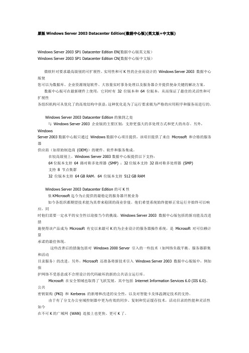
原版Windows Server 2003 Datacenter Edition(数据中心版)(英文版+中文版)Windows Server 2003 SP1 Datacenter Edition EN(数据中心版英文版)Windows Server 2003 SP1 Datacenter Edition CN(数据中心版中文版)微软针对要求最高级别的可扩展性、实用性和可K性的企业而设计的Windows Server 2003 数据中心版使您可以为数据库、企业资源规划软件、大容量实时事务处理以及服务器合并提供使命关键的解决方案。
数据中心版可在最新硬件上使用,它同时有32 位版本和64 位版本,从而保证了最佳的灵活性和可扩展性各组织机构可从优化了的高效结构中获益,这种优化是为了运行要求极为严格的应用程序和服务而进行的。
Windows Server 2003 Datacenter Edition的独到之处与Windows Server 2003 企业版的主要区别:支持更强大的多处理方式和更大的内存。
另外,WindowsServer 2003数据中心版只通过Windows数据中心项目提供,该项目提供了来自Microsoft 和合格的服务器供应商(如原始制造商(OEM))的硬件、软件和服务集成。
在较高级别上,Windows Server 2003数据中心版提供以下支持:64位版本支持64 路对称多处理器(SMP) ;32位版本支持32路对称多处理器(SMP)支持8 节点集群32 位版本支持64 GB RAM,64 位版本支持512 GB RAMWindows Server 2003 Datacenter Edition的可K性依KMicrosoft迄今为止提供的最稳定的服务器开展业务如今各组织都期望技术能为其带来稳固的商业价值。
他们希望系统始终能够正常运行并始终可以响应,同时他们需要一定水平的安全性以迎接当今的挑战。
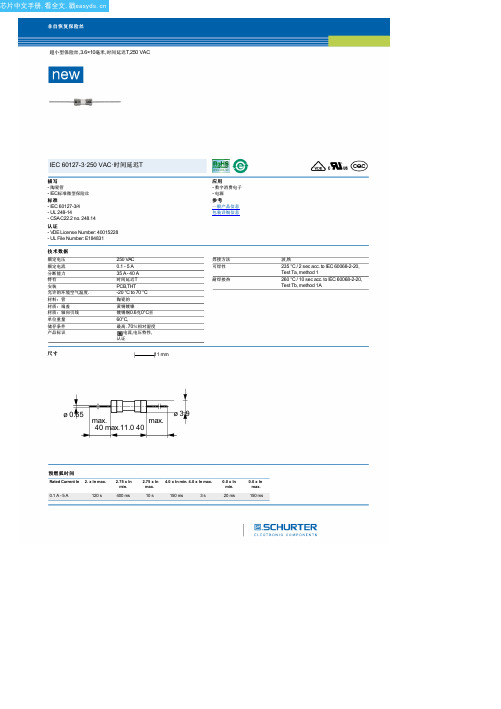
8020.0516.xx中文资料(Schurter)中文数据手册「EasyDatasheet - 矽搜」
ø 0.65
ø 3.9
max.
max.
40 max.11.0 40
预燃弧时间 Rated Current In 2. x In max.
0.1 A - 5 A
120 s
2.75 x In min.
400 ms
2.75 x In max.
10 s
4.0 x In min. 4.0 x In max.
认证
- VDE License Number: 40015228 - UL File Number: E184831
技术数据
额定电压 额定电流 分断能力 特有 安装
允许的环境空气温度.
材料:管 材质:端盖 材质:轴向引线 单位重量 储存条件 产品标识
250 VAC 0.1 - 5 A 35 A - 40 A 时间延迟T PCB,THT -20 °C to 70 °C
芯片中文手册,看全文,戳
非自恢复保险丝
超小型保险丝,3.6×10毫米,时间延迟T,250 VAC
IEC 60127-3·250 VAC·时间延迟T
描写
- 陶瓷管 - IEC标准微型保险丝
标准
- IEC 60127-3/4 - UL 248-14 - CSA C22.2 no. 248.14
陶瓷的
黄铜镀镍
镀锡铜0.6克0°C至 60°C, 最高. 70%相对湿度
,电流,电压特性,
认证
尺寸
11 mm
应用
- 数字消费电子 - 电源
参考 一般产品信息 包装详细信息
焊接方法 可焊性
耐焊接热
波,铁 235 °C / 2 sec acc. to IEC 60068-2-20, Test Ta, method 1 260 °C / 10 sec acc. to IEC 60068-2-20, Test Tb, method 1A
2003年版Expedition第三次印刷产品说明书

April 2003Third PrintingQuick Reference2L1J-19G217-ACExpeditionLitho in U.S.A.Fuel Tank Capacity– Your vehicle’s fuel tank can accommodate 28 gallons of gasoline. Yourvehicle is designed to use "Regular" unleaded gasoline with pump (R+M)/2 octane ratingof 87 for optimum performance. The use of gasoline with lower octane ratings maydegrade performance.Tire Pressure– Your tire pressure is properly set at the dealership according to therecommended specifications found on the Certification Label located on the front doorlatch pillar on the driver’s side. Please check your tire pressure during routine maintenanceand seasonal changes. Warning:Improperly inflated tires can affect vehicle handling andcan fail suddenly, possibly resulting in loss of vehicle control.Fuses– If electrical components in the vehicle are not working, a fuse may have blown. Formore information about changing a fuse, please consult your Owner’s Guide.Fuel Pump Shut-Off Switch – After a collision, if the engine cranks but does not start, thefuel pump shut-off switch may have to be reset. The switch is located in the left rearquarter trim panel, near the liftgate. For complete details on resetting the switch, pleaseconsult your Owner’s Guide.Changing the Tires– If you get a flat tire while driving, do not apply the brake heavily.Instead, gradually decrease your speed. Hold the steering wheel firmly and slowly move toa safe place on the side of the road. Your vehicle is equipped with a spare tire that may beused as a spare or a regular tire.Location of the Spare Tire and ToolsItem LocationSpare Tire Under the vehicle, just forward of the rear bumperJack Tools and Under the access panel, located in the floorJacking Instructions compartment behind the third row seatRoadside Emergencies– To fully assist if you should have a vehicle concern, Ford MotorCompany offers a complimentary roadside assistance program. This program is separatefrom the New Vehicle Limited Warranty. The service is available: 24 hours, seven days aweek for the Basic Warranty period (Canada) or New Vehicle Limited Warranty period (U.S.)of three years or 36,000 miles. Roadside assistance will cover:Changing a flat tire Jump-starts Limited fuel deliveryLockout assistance Towing of your vehicleRoadside Assistance CentersCountry Phone NumberUnited States(800) 241-3673Canada(800) 665-2006For complete details on any roadside assistance concern, see the Roadside Emergenciessection, or the Customer Assistance section in your Owner’s Guide.(if equipped)For information on other types of radios,please refer to your Owner’s Guide.Scan Function–In radio mode, pressto hear a sampling of all listenablestations. In CD mode, press to hear abrief sampling of all selections on thecurrent CD.Shuffle Function– Press to engage thedesired shuffle mode. SHUFFLE DISCrandomly plays tracks from all CDs;SHUFFLE TRK plays all selections fromthe current CD in random order.Loading CD– Press to open the CD door,then load a CD into the player. PressLOAD and then a preset number toselect a slot. Press and hold LOAD toactivate autoload.Volume/Power Control – Press thecontrol to turn the audio system on oroff. Turn the control to raise or lowervolume. The speed sensitive volumefeature automatically adjusts radiovolume in accordance with vehicle speedto compensate for road and wind noise.To engage, press and hold the volumecontrol for five seconds (with the radioon), then simultaneously press SEL tochoose the compensation level.AM/FM and CD Select – In radio mode,press AM/FM to select AM or FMfrequency bands. In CD mode, pressAM/FM to stop play and begin radio play.To begin CD play while in radio mode,press the CD control.Disc/Tune Adjust– In radio mode, press tomove to the next frequency up or downthe band. In CD mode, press to select adisc in the CD player.Digital Signal Processing– Press DSP andthen SEL to choose the desired signalmode (DSP OFF, NEWS, JAZZ CLUB, HALL,CHURCH, STADIUM).Seek Function– In radio mode, press tomove to the next listenable station up ordown the band. In CD mode, press toselect the next/previous track on thecurrent disc.Setting the Clock– Press MENU untilSELECT HOUR or SELECT MINUTE isdisplayed. Press SEL to set the time. PressMENU again to disengage the clock mode.Setting Memory Preset Stations– SelectAM, FM1, or FM2 band, then select astation. Next, press and hold a numberedcontrol until the sound returns.ABDCEFIJHGAIJEXPEDITION2003modelQuick Reference Guide23MODELEXPEDITIONQUICKREFERENCEGUIDEHFCDETo open the liftgate glass, push the button(figure a) under the center of the license platelamp shield.To open the liftgate, place your hand on top ofthe liftgate handle (figure b) and pull. Do notpull the handle from the bottom. To close, makecertain the rear window is closed, and then pushthe liftgate closed until it latches securely.Do not open the liftgate or liftgate glass in agarage or other enclosed area with a low ceiling.Y ou can also unlock/lock the liftgate and liftgateglass using your remote entry system.Folding the OutboardSeats to a Load Floor PositionTo fold the seats to a load floor position, liftthe lever (lever 1) located on the outboardside of the seat to release the seat back.Ensure that the seat back is locked in thedown position by applying pressure to it. Tolower the seat further to the full-loweredposition for maximum cargo capacity, locatethe pull strap at the front of the seat, thenpull forward to release the seat into akneel-down load floor position. A moderateforce may be required to move the seatforward and down.Exiting the Third Row SeatPull up on the lever (lever 2) located at theback of the second row seat. First, the seatback will fold forward to the cushion, thenthe seat will flip forward.To return the seat to the upright position,push the seat down and back until it islatched to the floor. Then, lift the seat backto the upright position.(continued)Folding the 20% Middle Seat (if equipped)to a Load Floor PositionTo fold the seat, pull the release straplocated between the seat cushion and the seatback to release the folding seat latch. With thelatch released, the seat back can be lowered intothe load floor position.Before folding the second row seats, ensure that the head restraints are fully loweredand that all items have been removed from in front of and on the seats.G*f2l1j-19g217-ac*Entering the Third Row SeatPull up on the lever (lever1) located on the sideof either outboard second row seat until theseat back folds forward to the cushion. Pull upon the lever (lever 2) located on the back of theseat. The seat will then flip forward.lever 1pull strapreleasestrapfigure afigure bReturning the Seats to the Upright Position from theFull-Lowered Floor PositionThe seat back cannot be returned to the upright positionuntil the seat is returned from the kneel-down position.To return the seat to the upright position, lift and pull theseat rearward until the latch is engaged. Do not attemptto unlatch the rear floor hooks while the seat is in thekneel-down position.With the seat in the flat back position, lift up on thelever (lever 1) located on the side of the seatcushion. This will allow the seat back to be lifted tothe upright locked position.lever 1Blever 2Ford Motor CompanyCustomer Relationship Center16800 Executive Plaza DriveP.O. Box 6248Dearborn, MI 481211-800-392-3673 (FORD)(TDD for the hearing impaired: 1-800-232-5952)This Quick Reference Guide is not intended to replace your vehicle Owner’sGuide which contains more detailed information concerning the features ofyour vehicle, as well as important safety warnings designed to help reducethe risk of injury to you and your occupants. Please read your entire Owner’sGuide carefully as you begin learning about your new vehicle and refer tothe appropriate sections when questions arise.All information contained on this Quick Reference Guide was accurate at thetime of duplication. We reserve the right to change features, operationand/or functionality of any vehicle specification at any time. Your Ford dealeris the best source for the most current information.For detailed operating and safety information, please consult your Owner’s Guide.CAUTION: DO NOT USE CD WITH ADHESIVE LABEL**CDs with adhesive labels and irregularly shaped CDs may get stuck in the CD player. HomemadeCDs should be identified with permanent felt tip marker rather than adhesive labels.*Refer to the minimum configuration requirements located on the back panel of the CD jacket.3Service Engine Soon LampIlluminates briefly to ensure thesystem is functional. If the lightcomes on after the engine isstarted, refer to your Owner’s Guide.To help prevent activation, always secureyour fuel cap by turning it clockwise 1/8 of aturn until it stops.Please note that if the fuel cap is not properlysecured, the warning "Check Fuel Cap" will bedisplayed on the optional message center. Thewarning will be reset once the cap is properlytightened and your vehicle is driven a shortdistance. If your vehicle is not equipped with amessage center, the Service Engine Soon Lampwill illuminate.ABS Warning LampIlluminates briefly when the ignitionis turned to the ON position. In anemergency, apply continuous forceon the brake to prevent wheel lockwhen braking on slippery surfaces - donot pump your brakes. Any pulsation or noiseyou may feel or hear is normal.Hazard Flasher ControlPress to activate all hazard flasherssimultaneously in an emergency to warn trafficof vehicle breakdown, approaching danger, etc.Press the control again to turn the flashers off.The hazard flashers can be operated when theignition is off.Message Center (if equipped)Please see Additional Features for more details.Air Flow AdjustY ou can direct or shut off the air flow from theinstrument panel registers. Turn the satin steelportion on the round register module clockwiseto eliminate air, or counterclockwise to openthe air vents. Push and move the vent knob inthe direction you wish to adjust the airflow.Audiophile In-Dash Six-CD Radio(if equipped)Please see reverse side for more details.2567Turn Signal &Wiper/WasherControl4Service EngineSoon LampABSWarningLampAudiophileIn-Dash Six-CDRadio (if equipped)12Gearshift/OverdriveControl11Control-TracFour-WheelDrive Control(if equipped)14SpeedControl13SteeringWheel Controls(if equipped)6HazardFlasherControl16HoodRelease10Rear WindowDefroster5Rear Window DefrosterPress to activate rear window defrost. Therear defrost indicator will illuminate. Whenin operation, the rear window defrosteralso defrosts the side view mirrors. The rearwindow defroster will automatically turnoff after approximately 10 minutes ofoperation. Press the control again tore-engage if needed.Control-Trac Four-Wheel Drive Control(if equipped)2H (2WD HIGH) delivers powerto the rear wheels only, andis the optimum position forsmoothness and fueleconomy. A4WD (4X4 AUTO)automatically delivers powerto all four wheels, as required, forincreased traction. 4H (4X4 HIGH) providesmechanically locked four-wheel drive powerto all four wheels. 4L (4X4 LOW) providesmechanically locked four-wheel drive whenextra power at reduced speeds is required.To shift from 2H to A4WD or 4H, move thecontrol at any forward speed up to 55 mph.To shift from A4WD to 4H, move the controlat a stop or while driving at any speed. Toshift to or from 4L, bring the vehicle to a stopand keep the brake pedal depressed. Next,place the gearshift in N (Neutral), and thenmove the control to 4L.When shifting from one four-wheel driveposition to the next, a mechanical noise maybe heard. This is normal and no serviceshould be required.Gearshift/Overdrive ControlOverdrive is the normal drive position forthe best fuel economy. Only deactivate(OFF) overdrive when: drivingwith a heavy load, towing atrailer up or down steephills, or when additionalengine braking is desired.To deactivate, press theswitch located on theend of the gearshift lever.104AdvanceTrac TM System(if equipped)This system provides a stabilityand traction enhancementfeature by detecting andcontrolling wheel spin. Thesystem defaults to on, however,the system does not function whenthe vehicle is traveling in R (Reverse), or ifequipped with four-wheel drive, in 4L. Ifyou should become stuck, try switching thesystem off by pressing the button on thecenter console.Keyless Entry SystemWith this control you can lock or unlockall doors without using a key. First, enteryour five-digit program code and thenpress the corresponding quick key:Unlock all doors = 3-4Lock all doors = 7-8 and 9-0simultaneouslyClimate Controlled Seats(if equipped)Push the left portion of the control toheat the seat back and the seat cushion. Ared light will illuminate when the systemis engaged. Push again to disengage. Pushthe right portion to cool the seat backand the seat cushion. A blue light willilluminate when the system is engaged.Push again to disengage. When in theheat or cool mode, rotate thethumbwheel to select the desired levelfrom 0 (OFF) to 5 (MAX). If in the coolmode and setting 1 is selected, the seat(s)will provide vent cooling only (the sametemperature as cabin air).Once the feature is activated, pleaseallow five minutes for the temperaturelevel to stabilize. Some initial blower noiseshould be expected at the beginning ofthe cool cycle.The climate control seats turn off afterapproximately 15 minutes in heat mode andapproximately 30 minutes in the cool modeto minimize unintended drain on thevehicle’s power supply.The climate control seat system includes anair filter that has to be replaced periodically.For more information, please consult yourOwner’s Guide.Message Center (if equipped)The message centerdisplays importantvehicle informationthrough a constant monitor of vehicle systems(with the ignition in the ON position). Thesystem will notify you of potential vehicleproblems with a display of system warningsfollowed by a long indicator chime. You mayselect display features on the message centerby pressing the Info or Setup buttons. TheReset button may be used to reset selectfunctions in the Info and Setup menus.For complete details on the message centerdisplay features, please refer to yourOwner’s Guide.Reverse Sensing System (if equipped)This sonar and radar system sounds a tone towarn the driver if an obstacle is detectedwithin approximately 20 feet behind the rearbumper while the vehicle moves in reverse atspeeds less than 6 mph. RSS defaults to ON,but can be disabled using the message centerfunctions when the ignition is ON, and thegearshift is in R (Reverse).Tire Pressure Monitoring System (if equipped)Using radio-frequency pressure sensors, thissystem monitors tire pressure on all tiresincluding the spare, and provides the driverwith a warning message when pressure isseverely low or high. If alerted, the system canbe reset using the message center functions.915Power AdjustableFoot PedalsIn order to help you fully appreciate the countless features of your new Expedition, we invite you to explore this easy-to-use Quick Reference Guide. Using this Guide in conjunction with the Interactive Owner Experience CD Rom, you can briefly hear how to operate the features listed to the right once you place the CD into any audio CD player.Find the numbered call-outs from the photograph of the instrument panel located in the center of the Quick Reference Guide, and then select the corresponding numbered audio track on the CD. For more comprehensive information, place the CD into any computer,* or consult your Owner’s Guide.This vehicle handles differently from anordinary passenger car in drivingconditions which may occur on streetsand highways and off-road. DRIVE WITH CARE AND WEAR A SAFETY BELT AT ALL TIMES. Ford urges you to read the Owners’ Guide and Driving Your SUV or Truck Supplement for further information on safe driving precautions and instructions.MessageCenter(if equipped)27Headlampand PanelDimmer Control1198Headlamp and Panel Dimmer ControlRotate clockwise oneposition from off toturn on the parkinglamps. Rotate twopositions to also turnon the headlamps. Rotate counterclockwiseto activate autolamp, which provides light-sensitive automatic on-off control of theexterior lights and keeps them on for a shortperiod of time after the ignition is turnedOFF. When the control is in any positionexcept high beams or off, pull the controltoward you to activate the foglamps.Turn Signal & Wiper/Washer ControlPush downto activatethe leftturn signal,or up to activate the right turn signal. OnEddie Bauer vehicles, the lower portion ofthe corresponding side view mirror will blinkto provide an additional warning to otherdrivers that your vehicle is about to turn.For front-wiper operation, rotate the ringon the left to the desired interval, low- orhigh-speed position. When in theintermittent position, rotate the control upfor fast and down for slow intervals. Thespeed-sensitive feature also allows the wipersto adjust automatically as the vehicle’s speedchanges when the wiper control is set on theintermittent settings. Push the end of thestalk briefly for a single wipe (no wash).Push and hold to activate the washer.The ring on the right operates the rear-window wiper. Rotate the control to INT 2(slow interval), INT 1 (fast interval), orwasher position.For extended wiper blade quality, occasionalcleaning of the wiper blades is required.3Note:The transmission shift strategy willslightly delay transmission upshift in coldweather to decrease the time required towarm up the engine and produce heat inthe passenger compartment.Steering Wheel Controls (if equipped)For audio control operation, press thecontrol with the musical note to selectwhich media to play. Depending on themode, press MEM to select a preset station,the next selection on a tape, or the nexttrack on a disc. Use VOL to adjust volume.For climate control operation, press TMP upor down to adjust temperature. Press thecontrol with the fan icon up or down toadjust fan speed.Speed ControlTo operate, the speed controlmust be ON and the vehiclespeed must be greater than30 mph. To set a speed,press SET +. To set a higherspeed, press SET + again.To set a lower speed,press CST -. Pressing RESwill return to a previouslyset speed. To turn thespeed control off, pressthe OFF button, or depress the brakepedal to disengage.Power Adjustable Foot PedalsPress and hold the rocker controlto adjust the accelerator andbrake pedal toward you or awayfrom you. Adjust the pedalsonly when the vehicle is stoppedand the gearshift lever is in theP (Park) position.Hood ReleasePull the hood release handle toward you.Next, release the auxiliary latch locatedunder the front center of the hood. Lift thehood until the lift cylinders hold it open.1215161314Air FlowAdjust81。
《Windows Server 2003组网教程(管理篇)》第6章:数据故障恢复的管理

6.1.1 卷状态 卷状态说明在“磁盘管理”中,该卷的图形视 图以及列表视图的“状态”栏中,始终会出现下面 的一种卷状态描述:
● 失败
● 失败的重复
失败的重复(子状态) 系统 启动 页面文件 故障转储 表明该卷是系统卷。 表明该卷是启动卷。
描述
表明该卷包含有页面文件。 表明该卷包含有故障转储,也称为内存转储。内存转储 可用于在Windows XP Professional或Windows Server 2003 家族操作系统意外停止时记录系统内存的内容。 表明由于某个磁盘出现故障且剩余动态磁盘检测到了 I/O错误,镜像卷或RAID-5卷上的数据不再具有容错能 力。只要在磁盘上的任一部分检测到I/O错误,则磁盘 的所有动态卷上都将显示警告图标。不具备容错能力的 动态卷将显示“良好(有危险)”状态。
采用RAID1或RAID5后,虽然一块硬盘的损坏不会导 致数据的丢失,但却无法避免2块或2块以上硬盘同时 损坏而产生的灾难性后果。由于电力或UPS等故障而导 致整个系统崩溃的可能性也不是没有,另外,由于病 毒或黑客的入侵也会造成数据不可恢复的损失。因此, 对数据及时进行备份,并在错误发生后迅速恢复就显 得尤其重要。
有危险
● 正在重新生成
● 重新同步
重新同步(子状态) 系统 启动 页面文件 故障转储 表明该 表明该卷包含有故障转储,也称为内存转储。内存转储 可用于在Windows XP Professional或Windows Server 2003 家族操作系统意外停止时记录系统内存的内容。
6.2.1 备份概述
如果系统的硬件或存储媒体发生故障,只要曾经及 时备份过,那么,就可以帮助我们保护数据免受意外 的损失。当硬盘上的原始数据被意外删除或覆盖,或 者因为硬盘故障而不能访问该数据时,可以方便的从 存档副本中还原该数据。
UF2003-T中文资料

UF2001 - UF20072.0A ULTRA-FAST RECTIFIERFeatures• Diffused Junction• Ultra-Fast Switching for High Efficiency• Surge Overload Rating to 60A Peak• Low Reverse Leakage Current• Lead Free Finish, RoHS Compliant (Note 4)Mechanical Data• Case: DO-15• Case Material: Molded Plastic. UL Flammability Classification Rating 94V-0• Moisture Sensitivity: Level 1 per J-STD-020D• Terminals: Finish – Tin. Solderable per MIL-STD-202, Method 208• Polarity: Cathode Band• Marking: Type Number• Ordering Information: See Page 3• Weight: 0.4 grams (approximate)DO-15Dim Min MaxA 25.40 ⎯B 5.50 7.62C 0.686 0.889D 2.60 3.60All Dimensions in mmMaximum Ratings and Electrical Characteristics@T A = 25°C unless otherwise specifiedSingle phase, half wave, 60Hz, resistive or inductive load.For capacitive load, derate current by 20%.Characteristic SymbolUF2001UF2002UF2003UF2004UF2005UF2006UF2007Unit Peak Repetitive Reverse VoltageWorking Peak Reverse VoltageDC Blocking Voltage (Note 5)V RRMV RWMV R50 100 200 400 600 800 1000 V RMS Reverse Voltage V R(RMS)35 70 140 280 420 560 700 V Average Rectified Output Current(Note 1) @ T A = 50°CI O 2.0 A Non-Repetitive Peak Forward Surge Current8.3ms Single Half Sine-Wave Superimposed on Rated Load I FSM60 A Forward Voltage @ I F = 2.0A V FM 1.0 1.3 1.7 V Peak Reverse Current @ T A = 25°Cat Rated DC Blocking Voltage (Note 5) @ T A = 100°CI RM5.0100μAReverse Recovery Time (Note 3) t rr50 75 ns Typical Total Capacitance (Note 2) C T50 30 pF Typical Thermal Resistance Junction to Ambient RθJA50 °C/W Operating and Storage Temperature Range T J, T STG-65 to +150 °CNotes: 1. Valid provided that leads are maintained at ambient temperature at a distance of 9.5mm from the case.2. Measured at 1.0MHz and applied reverse voltage of 4.0V DC.3. Measured at I F = 0.5A, I R = 1.0A, I rr = 0.25A. See figure 5.4. RoHS revision 13.2.2003. High temperature solder exemption applied, see EU Directive Annex Note 7.5. Short duration pulse test used to minimize self heating effect.Please click here to visit our online spice models database.0.010.11.0100.60.81.01.21.4I ,I N S T A N T A N E O U S F O R W A R D C U R R E N T (A )F V , INSTANTANEOUS FORWARD VOLTAGE (V)Fig. 2 Typical Forward CharacteristicsF00.40.81.21.62.0255075100125150175200I ,A V E R A G E F O R W A R D R E C T I F I E D C U R R E N T (A )(A V )T , AMBIENT TEMPERATURE (C)Fig. 1 Forward Current Derating CurveA°I , P E A K F O R W A R D S U R G E C U R R E N T (A )F S M 0204060110NUMBER OF CYCLES AT 60Hz Fig. 3 Peak Forward Surge Current100110100110100C , T OT A L C A P A C I T A N C E (p F )T V , DC REVERSE VOLTAGE (V)Fig. 4 Typical T otal CapacitanceROrdering Information (Note 6)Device Packaging ShippingUF2001-T DO-15 4K/Tape & Reel, 13-inchUF2002-T DO-15 4K/Tape & Reel, 13-inchUF2003-T DO-15 4K/Tape & Reel, 13-inchUF2004-T DO-15 4K/Tape & Reel, 13-inchUF2005-T DO-15 4K/Tape & Reel, 13-inchUF2006-T DO-15 4K/Tape & Reel, 13-inchUF2007-T DO-15 4K/Tape & Reel, 13-inchNotes: 6. For packaging details, visit our website at /datasheets/ap02007.pdf.IMPORTANT NOTICEDiodes Incorporated and its subsidiaries reserve the right to make modifications, enhancements, improvements, corrections or other changes without further notice to any product herein. Diodes Incorporated does not assume any liability arising out of the application or use of any product described herein; neither does it convey any license under its patent rights, nor the rights of others. The user of products in such applications shall assume all risks of such use and will agree to hold Diodes Incorporated and all the companies whose products are represented on our website, harmless against all damages.LIFE SUPPORTDiodes Incorporated products are not authorized for use as critical components in life support devices or systems without the expressed written approval of the President of Diodes Incorporated.。
ECS-120-20-33-A-E-L-TR中文资料(ECS)中文数据手册「EasyDatasheet - 矽搜」
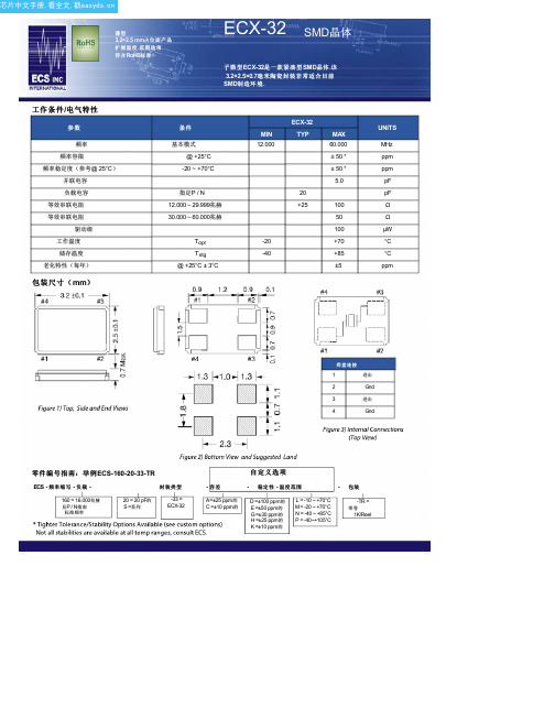
L = -10 ~ +70°C M = -20 ~ +70°C N = -40 ~ +85°C P = -40~+105°C
-TR =
带卷
1K/Reel
芯片中文手册,看全文,戳
发达国家频率
频率
MHz
16.000 18.432 19.6608 20.000 24.000 25.000 27.000 30.000 32.000 36.000 40.000 48.000
代码
160 184 196 200 240 250 270 300 320 360 400 480
袖 珍 磁 带 尺 寸 ( mm)
ECid
基地 密封 终奌站
描述 Metal
陶瓷
缝/ EB
钨(金属化)
电镀
RoHS
黄金/镍 表面/下
标准(无铅)
芯片中文手册,看全文,戳
薄型
3.2×2.5 mm占位面产品 扩展温度 .范围选项 符合 RoHS标准
ECX-32 SMD晶体
子 微 型 ECX-32是 一 款 紧 凑 型 SMD晶 体 .该 3.2×2.5×0.7毫米陶瓷封装非常适合目前 SMD制 造 环 境 .
工 作 条 件 /电 气 特 性
参数
频率 频率容限
频率稳定度(参考@ 25°C)
并联电容 负载电容 等效串联电阻 等效串联电阻
驱动级 工作温度 储存温度 老化特性(每年)
包 装 尺 寸 ( mm)
条件 基本模式
@ +25°C -20 ~ +70°C
指定P / N 12.000〜29.999兆赫 30.000〜60.000兆赫
Topr Tstg @ +25°C ± 3°C
米高2003说明书
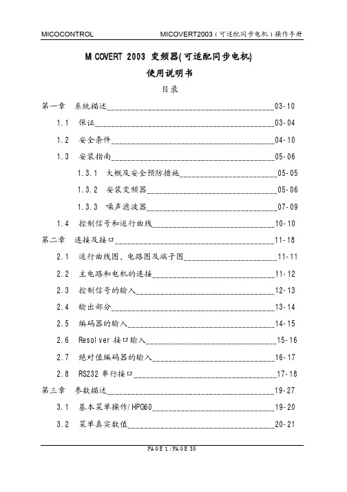
PAGE 3 / PAGE 35
MICOCONTROL
MICOVERT2003 可适配同步电机 操作手册
此保修条款不影响客户在法律授权下的法定权利及客户与销售商之间的 购销协议所赋予的权利 1.2 安全条件
常识 由于存在高压 不允许变频器在没有保护外壳的情况下运行 否则会引 起人员的伤亡 只有具有熟练工艺的人员才能操作 而且必须符合国际及当地的安全条 件及法规 如 DIN VDE0100 DIN VDE 0110 IEC 364 IEC 664
运输及安装 变频器的运输必须十分小心 请不要接触电子和端子部分 这些元件有 可能由于人手上的静电而有所损坏 在接线时 请不要打开变频器的保 护外壳 所有接线端子都是外露的 请注意变频器周围的通风
PAGE 4 / PAGE 35
MICOCONTROL来自MICOVERT2003 可适配同步电机 操作手册
运行条件 所有变频器必须配备符合国家和当地的安全法规的安全设施 如欧洲法 规 EN81 变频器的外壳必须盖上 并且正确安装内置滤波器 由于电容的关系 即使关掉电源后 变频器仍然带有危险的高压 请不 要触摸 变频器断电后至少 5 分钟后 才能打开变频器的外壳
CT中文手册【范本模板】

Clinical Development - PMS Greater China BL SystemPhilips螺旋 CT 系列UltraZ操作手册Clinical Development - PMS Greater China BL System系统介绍:有关这本手册--手册章节介绍:该手册由若干个信息功能章节构成,所有章节如下:第一章:系统介绍第二章:控制及显示系统第三章:系统的开启与关机第四章:总体设制自动声音的录制预制窗宽窗位的修改扫描方案的预制日期与时间的设定第五章 : 扫描控制操作按钮的使用,工作流程标识,主菜单标识 X线系统的预热移动病人至扫描床Clinical Development - PMS Greater China BL System病人的摆位输入病人信息选择扫描方案执行定位计划扫描扫描采集回顾式重建穿刺定位扫描团注分析扫描第六章 : 图像显示及分析二维显示多平面重组最大投影密度表面遮盖成象4D 血管造影第七章:图像的摄影第八章:图像的存档Clinical Development - PMS Greater China BL System第一章常规介绍此手册将采用一些特殊的标识及格式介绍相关信息操作员的信息输入:针对操作员的指令,系统将在如下的对话框中显示指令信息:1。
如果输入的工作涉及到鼠标器,系统将在对话中提示操作员使用鼠标器的某一个键“点击”屏幕上的某一个功能选项.2。
如果输入工作涉及到键盘上的某一个功能键,系统将提示操作员“按下"该功能键。
3.如果输入工作涉及到键盘录入,系统将提示精确的输入数量及字符类型系统的提示及相关信息系统会在当前屏幕上显示提示信息的对话框屏幕按键;工作流程块及菜单键的使用扫描器的操作是通过使用鼠标器及从监视器上选择用户要求的扫描序列实现的。
屏幕按键的介绍屏幕按键是设置在扫描参数前的钻石状的按钮,操作人员可以简单地通过移动鼠标至该按钮上,然后单击鼠标器,此按钮将变黄为黄色,代表选择结束。
Lotto Skyworks 2003 扫描指南说明书

LOTTO SKYWORKS 2003This WARSUG guide is for scanning the Lotto Skyworks 2003. The information in here is mostly guesswork as it’s usually next to impossible to find out the correct channel allocations until the afternoon of the event. Based on previous years however, we can make an “educated guess” on what to listen to.WA POLICE SERVICEPerth district area channel: Ch 34 468.675 Cannington district area channel: Ch 08 468.025Special Events Channels: Ch 25 468.425 Ch 03 467.900Ch 63 468.400 Ch 38 468.775Ch 51 469.100 Ch 45 468.950Ch 43 468.900 Ch 61 469.350Mobile Police Facility Channel: Ch 09 468.050Police Air Wing 131.600 Note:Channel allocations for the evening are often given out to cars asthey book onto the city channel (Ch 34) throughout the afternoon.THE MIX 94.5Studio to announcer talkback: 492.425 Fireworks cues: 494.500Note: On the talkback frequency, you will probably hear only the operatorin the studio, you won’t hear the announcer. The cues are short “beep” sounds to trigger the release of each firework. There may also be some voice traffic before the start of the event.WESTRAILMetro Train Control418.725 Customer Service and Security Channel:419.750 Note: After the SkyWorks has finished, you’ll hear lots of activity on the Westrail channels as the exodus of people reaches the City train station… Some of the callsigns you may hear are: Tango (Train riders: on-train security), Delta (Roving patrols), Alpha (Aboriginal Liaison), CSA (Customer Service Assistant) and SSO (Station Security Officer) TVW CHANNEL SEVEN161.2625 163.400463.025463.200463.875Note:Not much info on the above frequencies, but there’s a reasonable chance of hearing the outside broadcast (OB) crews since it’s going to be replayed on TV later that night…WA STATE EMERGENCY SERVICECh 01 468.600 Ch 02 468.625 Ch 03 468.650 Ch 06 467.225 Ch 07 467.475Ch 08 467.725Note:The SES are always active around the Skyworks event performing duties such as car park control, etc. They may be heard on any of the above channels…AIR SERVICESPerth Appr/Dep 123.700 118.700 Perth Radar128.100 Emergency 121.500Plane to Plane Talk123.450Note:These are the standard air frequencies for use in and around Perth. You may hear the police helicopter, TV station helicopters, light planes, etc...MARINE RADIOSea Search and Rescue: Ch 06156.300 Water Police: Ch 16 156.800 Ch 67 156.375 Ch 73156.675Ch 74156.725Note:May contain Water Police, Sea Search and Rescue, and possibly the barges themselves…OTHERBoat Torque Cruises 464.750 475.050 Spices Catering469.725 Amateur Repeater VK6RVP438.425UHF CB Ch 8476.600COUNCILSCity of South Perth 471.300 471.600 Town of Victoria Park163.725Note:Council rangers may be on these channels. Unfortunately, the City of Perth use a trunking system which is very difficult to monitor…Copyright © 2003 WA Radio Scanner Users GroupWeb: /。
smarty中文手册

Smarty 教 程 Copyright © by ispi of Lincoln, Inc. - 05/05/2007目 录一、模板设计 (1)1.基本语法 (1)Comments [注释] (1)Functions [函数] (1)Attributes [属性] (1)Embedding Vars in Double Quotes [双引号里值的嵌入] (2)Math[数学运算] (2)2.变量 (3)Variables assigned from PHP [从PHP分配的变量] (3)Associative arrays [关联数组] (4)Array indexes[数组下标] (4)Objects[对象] (5)Variables loaded from config files [从配置文件读取的变量] (6){$smarty} reserved variable [{$smarty}保留变量] (7)Request variables[页面请求变量] (7){$smarty.now} (8){$smarty.const} (8){$smarty.capture} (9){$smarty.config} (9){$smarty.section}, {$smarty.foreach} (9){$smarty.template} (9)3.Variable Modifiers [变量调节器] (10)capitalize [所有单词首字符大写] (10)count_characters[字符计数] (11)cat[连接字符串] (12)count_paragraphs[计算段数] (12)count_sentences[计算句数] (13)count_words[计算词数] (13)date_format[格式化日期] (14)default[默认值] (15)escape[编码] (16)indent[缩进] (17)lower [小写] (18)nl2br [换行符替换成<br />] (19)regex_replace [正则替换] (19)replace [替换] (20)spacify [插空] (21)string_format [字符串格式化] (22)strip [去除(多余空格)] (22)strip_tags [去除html标签] (23)truncate [截取] (24)upper [大写] (25)wordwrap [行宽约束] (26)bining Modifiers [组合使用变量调节器] (27)5.Built-in Functions [内建函数] (28)capture [获取页面输出] (28)config_load [配置加载] (29)foreach,foreachelse [循环处理数组] (31)include [包含文件] (36)include_php [包含PHP脚本] (37)insert [插入函数] (38)if,elseif,else (40)ldelim,rdelim [输出分隔符] (42)literal [文本处理] (42)php [嵌入php脚本] (43)section,sectionelse [遍历数组] (43)strip [去处首尾空格和回车] (55)6.Custom Functions[自定义函数] (56)assign [为模板变量赋值] (56)counter [计数] (56)cycle [轮转使用值] (58)debug [调试输出] (59)eval (60)fetch [取文件、HTTP、FTP] (61)html_checkboxes [html 复选框] (62)html_image [html 图片] (64)html_options [html下拉列表] (65)html_radios [html 单选框] (67)html_select_date [html 日期下拉列表] (69)html_select_time [html 时间下拉列表] (74)html_table [html 制表] (79)math [数学运算] (81)mailto (82)popup_init (84)popup [创建javascript弹出窗口] (85)textformat [文本格式化] (91)7.Config Files [配置文件] (95)8.Debugging Console [调试控制台] (97)二、Smarty For Programmers [程序员篇] (98)9.Constants [常量] (98)SMARTY_DIR [Smarty目录] (98)10.Variables [变量] (98)$template_dir [模板目录变量] (98)$compile_dir [编译目录变量] (98)$config_dir [配置目录变量] (99)$plugins_dir [插件目录变量] (99)$debugging [调试变量] (99)$debug_tpl [调试模板变量] (100)$debugging_ctrl [调试控制变量] (100)$global_assign [全局配置变量] (100)$undefined [未定义变量] (100)$autoload_filters [自动加载过滤器变量] (101)$compile_check [编译检查变量] (101)$force_compile [强迫编译变量] (101)$caching [缓存变量] (102)$cache_dir [缓存目录变量] (102)$cache_lifetime [缓存生存时间变量] (102)$cache_handler_func [缓存处理函数变量] (103)$cache_modified_check [缓存修正检查变量] (103)$config_overwrite [配置覆盖变量] (103)$config_booleanize [配置布尔化变量] (103)$config_read_hidden [配置读取隐藏变量] (104)$config_fix_newlines [配置固定换行符变量] (104)$default_template_handle r_func [默认模板处理函数变量] (104)$php_handling [PHP处理变量] (104)$security [安全变量] (105)$secure_dir [安全目录变量] (106)$security_settings [安全配置变量] (106)$trusted_dir [信任目录变量] (107)$left_delimiter [左结束符变量] (107)$right_delimiter [右结束符变量] (107)$compiler_class [编译类变量] (107)$request_vars_order [变量顺序变量] (107)$request_use_auto_globals [自动全局变量] (108)$compile_id [编译ID变量] (108)$use_sub_dirs [子目录变量] (108)$default_modifiers [默认修正器变量] (108)$default_resource_type [默认源类型变量] (109)11.Methods [方法] (109)append [添加] (109)append_by_ref [引用添加] (110)assign [赋值] (111)assign_by_ref [引用赋值] (111)clear_all_assign [清除所有赋值] (112)clear_all_cache [清除所有缓存] (112)clear_assign [清除赋值] (113)clear_cache [清除缓存] (113)clear_compiled_tpl [清除已编译模板] (114)clear_config [清除配置] (114)config_load [加载配置] (115)display [显示] (115)fetch [取得输出的内容] (117)get_config_vars [取配置变量的值] (118)get_registered_object [取得已注册的对象] (119)get_template_vars [取得模板变量的值] (119)load_filter [加载过滤器] (120)register_block [注册一个块] (121)register_compiler_function [注册编译函数] (122)register_function [注册函数] (123)register_modifier [注册修饰器] (123)register_object [注册对象] (124)register_outputfilter [注册输出过滤器] (124)register_postfilter [注册提交过滤器] (125)register_prefilter [注册预过滤器] (125)register_resource [注册资源] (126)trigger_error [触发错误] (127)template_exists [模板是否存在] (127)unregister_block [注销一个块] (127)unregister_compiler_function [注销编译函数] (127)unregister_function [注销函数] (128)unregister_modifier [注销修饰器] (128)unregister_object [注销对象] (128)unregister_outputfilter [注销输出过滤器] (129)unregister_postfilter [注销提交过滤器] (129)unregister_prefilter [注销预过滤器] (129)unregister_resource [注销资源] (129)12.Caching [缓存] (130)Multiple Caches Per Page [每页多个缓存] (133)Cache Groups [缓存集合] (135)Controlling Cacheability of Plugins' Output [控制插件输出的缓冲能力] (136)13.Advanced Features [高级特征] (138)Objects [对象] (138)Prefilters [预过滤器] (140)Postfilters [后过滤器] (141)Output Filters [输出过滤器] (141)Cache Handler Function [缓冲处理函数] (142)Resources [资源] (145)14.Extending Smarty With Plugins [利用插件扩展Smarty] (149)How Plugins Work [插件如何工作] (150)Naming Conventions [命名约定] (151)Writing Plugins [编写插件] (152)Template Functions [模板函数插件] (153)Modifiers [修正器插件] (155)Block Functions [区块函数插件] (156)Compiler Functions [编译函数插件] (158)Prefilters/Postfilters [预滤器/补滤器插件] (159)Output Filters [输出过滤插件] (161)Resources [资源插件] (162)Inserts [嵌入插件] (164)三、Appendixes [附录] (165)15.Troubleshooting [疑难解答] (165)Smarty/PHP errors [错误] (165)16.Tips & Tricks [使用技巧和经验] (167)Blank Variable Handling[空白变量处理] (167)Default Variable Handling[默认变量处理] (167)Passing variable title to header template[传递变量型标题给头模板] (168)Dates[日期] (169)WAP/WML[WAP/WML] (170)Componentized Templates[组合的模板] (171)Obfuscating E-mail Addresses[拒绝电子邮件地址] (173)17.Resources [相关资源] (174)18.BUGS [漏洞] (174)一、模板设计1.基本语法Comments [注释]模板注释被*号包围,例如 {* this is a comment *} 。
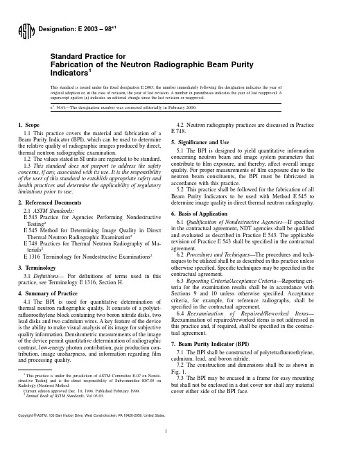
E2003
7.4Cadmium and lead shall be at least 99.9%pure elemen-tal material.7.5Boron nitride shall be hot-pressed,minimum 40%elemental boron.7.6The polytetrafluoroethylene block tolerances shall be 610%.7.7The tolerances for the holes and the grooves shall besuch that the disks and the wires do not fall out during use.8.Fabrication8.1Individual Components :8.1.1Form the polytetrafluoroethylene base by milling an8-mm thick sheet of the material into a 25-mm square.8.1.2Drill a 1661-mm hole in the center of the unit.8.1.3Mill two 4-mm diameter by 2-mm deep holes centered4-mm from adjacent corners on one face of the unit.8.1.4Cut two lengths of 0.761-mm diameter cadmiumwire,each 12-mm long.8.1.5Mill a groove in the base between the holes milled in8.1.3.The groove should be 0.04mm deeper and 0.04mmnarrower than the diameter of the wire cut in 8.1.4,so the wirewill be flush and tight.The groove may extend to the outsideedge of the unit (see Fig.1).8.1.6Repeat the process on the opposite face,makingcertain that the holes are not stacked upon each other.8.1.7Prepare a 4-mm diameter rod of boron nitride (a lathemay be used).8.1.8Cut off two 2-mm thick disks from the rod machinedin 8.1.7.8.1.9Prepare a 4-mm diameter rod of lead (a lathe may beused).8.1.10Cut off two 2-mm thick disks from the rod machined in 8.1.9.8.2Assembly :8.2.1Place the polytetrafluoroethylene block with the two holes and groove on the left side.8.2.2Insert a lead disk (as prepared in 8.1.9and 8.1.10)in the upper hole.8.2.3Insert a boron nitride disk (as prepared in 8.1.7and 8.1.8)in the lower hole.8.2.4Insert a cadmium wire piece (as prepared in 8.1.4)into the groove between the two disks,making certain the wire is flush,tight,and centered.8.2.5Turn the block over and orient it so that the groove and holes are on the left side.Repeat the steps specified in 8.2.1through 8.2.4.8.2.6The final assembly shall conform to Fig.1.9.Certification 9.1Upon request of the purchaser by contract or purchase order,any fabricator of the BPI described in this practice shall provide materials certification.To verify correct assembly and functionality,a comparison thermal neutron radiograph of the assembled BPI with that of a reference BPI (preferably on a single neutron radiograph)shall be provided.9.2The comparison thermal neutron radiograph of the assembled BPI along with a reference BPI shall show the following:9.2.1The disks and wires are properly placed and intact.9.2.2Using Method E 545(latest revision),calculate the values for thermal neutron,scattered neutron,gamma,and pair productioncontent.PolytetrafluoroethyleneCadmium 99.9%pureLead 99.9%pureBN-Boron nitrideHot-pressed,40%min elemental boronN OTE 1—Pb and BN disks are 4-mm in diameter and 2-mm thick (minimum thickness).FIG.1Beam PurityIndicator9.2.3The values should be comparable to those of thereference BPI.9.2.4Assign a unique identification number to the accept-able unit and mark the BPI.The identification number shall besuch that it shall not interfere with any density readings used tocalculate any exposure contributors (see Method E 545,latestrevision).9.3The comparison thermal neutron radiograph of theassembled BPI with the reference BPI shall meet quality levelCategory I specified in Method E 545,latest revision.9.4Any BPI fabricated in accordance with Method E 545from 1981through 1991is assumed to be a reference BPI (unless there is known to be a disqualifying deficiency).10.Records 10.1Complete records of the fabrication details shall be maintained by the manufacturing facility for three years or as specified in the basis of purchase.11.Keywords 11.1beam purity indicator;direct method;image quality indicator;neutron radiography;sensitivity indicatorThe American Society for Testing and Materials takes no position respecting the validity of any patent rights asserted in connection with any item mentioned in this ers of this standard are expressly advised that determination of the validity of any such patent rights,and the risk of infringement of such rights,are entirely their own responsibility.This standard is subject to revision at any time by the responsible technical committee and must be reviewed every five years and if not revised,either reapproved or withdrawn.Your comments are invited either for revision of this standard or for additional standards and should be addressed to ASTM Headquarters.Your comments will receive careful consideration at a meeting of the responsible technical committee,which you may attend.If you feel that your comments have not received a fair hearing you should make your views known to the ASTM Committee on Standards,at the address shown below.This standard is copyrighted by ASTM,100Barr Harbor Drive,PO Box C700,West Conshohocken,PA 19428-2959,United States.Individual reprints (single or multiple copies)of this standard may be obtained by contacting ASTM at the above address or at 610-832-9585(phone),610-832-9555(fax),or service@ (e-mail);or through the ASTM website().。
BR2003说明书
一、功能简介1.集重量显示器和配料控制器为一体。
2.双显示器显示。
(1)在等待计量状态:小显示器显示配方代码,大显示器显示秤重量。
(2)在计量状态:小显示器显示单种物料的动态计量重量值,大显示器显示秤内总重量。
(3)在设置状态:小显示器显示提示符,大显示器显示设定值。
3.可控制1-4种不同种类的物料。
4.提供过动控制(粗计量)、抖动控制(精计量)两种控制方式。
每种物料可独立选择各自的控制方式,设置各自的控制参数。
5.所有配料数据、系统功能数据均可通过面板按键输入,并存储于存储器内。
6.所有配料控制数据都具有断电保护功能。
7.零点自动跟踪。
8.按键后自动去皮重。
9.通过RS485接口输入设置配料控制数据和系统功能数据。
10.通过RS485接口输出配料完成量及工作过程代码。
11.配接专用打印机,记录每次配料的时间、配比、设定值和实际计量值。
12.在过动控制(粗计量)方式下,动态修正过动量控制参数。
13.预置9种配比,单键快速选择其一作为实际配比。
14.可与上位机(如工控机或BR2007专用控制器)组成集散控制系统,用于成套设备的集中控制和管理。
15.现场校秤。
二、技术规格电源:AC220V/50HZ±15%环境温度:0—50℃相对湿度:20—75%RH消耗功率:≤8W传感器:电阻应变式测力与称重传感器传感器激励电压:DC12V最大输入信号:24mv控制继电器:SSR固态继电器5个继电器触点容量:3A/220V外壳:盘装式仪表外壳外型尺寸:160×80×160mm开口尺寸:152×76mm三、名词解释目标重量值:每种物料的计量重量。
配比:多种物料目标重量值经实验室调配后的组合。
去皮:秤体的重量简称皮重。
仪表中记忆皮重的清除。
精称量:选用抖动控制法时,在测重值小于“目标重量值—精称量”时,自动控制为连续放料;当测重值达到和超过“目标重量值—精称量”时,自动控制为料门间开(t)时间、间闭(t.)时间的抖动放料。
- 1、下载文档前请自行甄别文档内容的完整性,平台不提供额外的编辑、内容补充、找答案等附加服务。
- 2、"仅部分预览"的文档,不可在线预览部分如存在完整性等问题,可反馈申请退款(可完整预览的文档不适用该条件!)。
- 3、如文档侵犯您的权益,请联系客服反馈,我们会尽快为您处理(人工客服工作时间:9:00-18:30)。
ER2000CT~ER2006CT
隔离超快恢复整流
电压
50至 600伏
当前
20.0安培
特征
•塑料包装已防护险商实验室 可燃性分类94V-O. 阻燃环氧模塑料.
•超过MIL-S-19500/228•低功耗,高效率环防护标 准. •低forwrd voltge,高电流能力•高浪涌能 力. •超快速恢复时间,高电压. •外延芯片建设. •在符合欧盟RoHS指令2002/95/EC
35
50
100 ns
CJ
85
pF
R Jc
3.0
O C/W
TJ ,TSTG
-50 to +150
OC
NOTES:
1. Measured at 1 MHz and applied reverse voltage of 4.0 VDC. 2. Reverse Recovery Test Conditions: I F=.5A, I R=1A, Irr=.25A. 3. Both Bonding and Chip structure are available.
. 058(1. 47) . 042(1. 07)
MECHANICALDATA •案例:每MIL-STD-750,方法 2026•极性铅焊:TO-220AB模压塑料•端子标示.
•标准包装:任何•重量 :0.0655盎司,1.859克.
最大额定值和电气 CHARACTERISTICSS 在25°C环境温度额定值除非另有规定.单相,半波,60赫兹,电阻或电感性负载. 对于容性负载,减免电流20%
Fig.2-典 型 正 向
特性
180 150 120
90
8.3ms Single Half Since-W ave JEDEC Method
60
25 PEAK FORWARD SURGE CURRENT,
0
1
2
5 10 20
NO. OF CYCLE AT 60HZ
Fig.4-最大不 - 重复浪涌电流
1000
O
TJ = 125 C 100
MICROAMPERES
TJ = 75 CO 10
INVSTANTANEOUS REVERSE CURRENT,
1.0 TJ = 25 CO
0.1
20
40
60
80 100
120
PERCENT OF RAT ED PEAK INVERSE VOLT GE, VOLT S
50 100
90
80
70
60 CAPACI5T0ANCE, pF
O
TJ = 25 C
40
30
20
10 1 2 5 10 20 50 100 200 500 REVERSE VOLTAGE, VOLTS
Fig.5-典型结电容
Typical Junction capacitance (Note 1)
Typical thermal Resistance (Note 3)
Operating Junction and Storage Temperature Range
SYMBOL ER2000CT
ER2001CT ER2001ACT ER2002CT
图 3典型反向特性
50
10
AMPERES
5 0 -2 0 0 V 3 0 0 -4 0 0 V
1.0
INSTANTANEOUS FORWARD CURR60E0VNT
ቤተ መጻሕፍቲ ባይዱ
T J= 25OC Pulse W idth=200us
0.1
0.75
0.95
1.15
1.35
1.55
1.75
INSTANTANEOUS FORWARD VOLTAGE, VOLTS
芯片中文手册,看全文,戳
ER2000CT~ER2006CT
额定值和特性曲线
20 16 12
安培
6
RESIST IVEORINDUCT IVE LOAD
4 平均正向电流,
0 0 20 40 60 80 100 120 140 160 CASETEMPERAURE, C O
Fig.1-正 向 电 流 降 额 曲 线
PARAMETER Maximum Recurrent PeakReverse Voltage
Maximum RMS Voltage
Maximum DC Blocking Voltage
Maximum Average Forward Current at Tc=90 o C PeakForward Surge Current : 8.3mssingle half sine-wave superimposed on rated load(JEDEC method) Maximum Forward Voltage at 10A Maximum DC Reverse Current T J =25 O C at Rated DC Blocking VoltageT J =100 O C Maximum Reverse Recovery Time (Note 2)
ER2003CT
ER2004CT
ER2006CT
UNITS
VR R M
50
100
150
200
300
400
600
V
VR MS
35
70
105
140
210
280
420
V
VD C
50
100
150
200
300
400
600
V
IF (AV)
20.0
A
IF S M
150
A
VF
0.95
1.3
1.7
V
I
R
1
µA
500
trr
