Ansys_12[1].0_CFX_官方教程__17
ansys12.0安装

Windows 7 下ansys12.0 的安装2010-08-28 01:52一、准备工作:1、依次点击开始——控制面板——程序和功能——打开或关闭windows功能——勾选Microsoft. NET Framework3.5.1下面的两个复选框,确定。
2、在光盘映像文件(.iso)解压文件夹中,找到MAGNITUDE文件夹,运行其中的ap120_calc.exe,然后出现命令提示符,问是否继续,需要选择“Y”或者“N”,键入字母"Y",然后就会在这个文件夹里面出现一个LICENSE.TXT的文本,留用。
(这一步只要在安装过程中的第5步之前做就可以了。
)二、安装过程:1、将下载的光盘映像文件(.iso)解压缩(或者用虚拟光驱加载。
虽然解压缩容易操作,但是有时会导致解压得到的文件不能正常使用,推荐使用光驱加载)。
2、在解压得到的文件夹中找到SETUP.EXE,运行SETUP.EXE。
3、首先安装第一项:基础环境。
Instal Required Prerequisites在出现的界面中点OK,开始安装.这里面当安装到 Framework 2.0 sp1时,(!!!虽然已经做了准备工作中的“1”,但是依旧)会出现如下错误提示:“必须使用“控制面板”中的“打开或关闭Windows功能”安装或配置Microsoft .NET Framewrok 2.0 SP1”点击确定即可,这时已经不会影响到安装了。
(解释:因为我们准备工作中已经用 Framework 3.5.1代替了 Framework 2.0 SP1,这里确定即可。
)4、然后安装第二项:ansys。
Install ANSYS, Inc.Products过程中会出现两处安装选项(各两个Skip),如果系统中没有安装PRO/E等,都勾选皆可。
安装过程中还需要填写计算机名(区别于用户名)。
5、安装第三项:Install ANSYS, Inc.License Manager安装过程中会提示需要安装证书,需要手动指定路径,指定准备工作第2步中生成的license.txt 文本。
ANSYS Workbench 12.1官方中文培训教程
Workshop 3 - Results
• You can also plot contours at specific frequencies. • Click RMB on the solution object and >Insert> Stress, Strain, or Deformation
– set the scoping to all faces on the beam – set the Spatial Resolution to Use Maximum – set the Orientation to Y Axis
Training Manual
ANSYS, Inc. Proprietary © 2009 ANSYS, Inc. All rights reserved.
• The Beam (3 m x 0.5 m x 25 mm) is made of Steel.
Constrain (Fix) Both Ends
ANSYS, Inc. Proprietary © 2009 ANSYS, Inc. All rights reserved.
WS3-2
July 2009 Inventory #002666
WS3-7
July 2009 Inventory #002666
Workshop 3 - Environment
– – – – – –
Training Manual
• In the Harmonic Response branch, apply one force to one edge.
There are two edges imprinted on the beam face. Switch to Edge selection mode as necessary and >Insert>Force. Use LMB and drag over surface to highlight to pick the applicable edge. Click “Apply” in the Details window In Details, change the “Defined By” to “Components” (i.e., XYZ). Enter 250 for “Y”. Leave Phase Angle = 0
完整版ansys 中文帮助手册----内容与目录
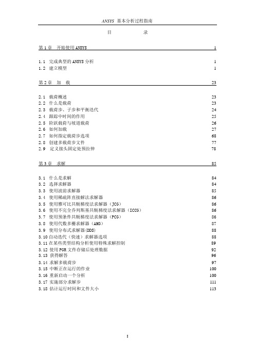
目录第1 章开始使用ANSYS 11.1 完成典型的ANSYS 分析 1 1.2 建立模型 1第2 章加载232.1 载荷概述23 2.2 什么是载荷23 2.3 载荷步、子步和平衡迭代24 2.4 跟踪中时间的作用25 2.5 阶跃载荷与坡道载荷26 2.6 如何加载27 2.7 如何指定载荷步选项68 2.8 创建多载荷步文件77 2.9 定义接头固定处预拉伸78第3 章求解853.1 什么是求解84 3.2 选择求解器84 3.3 使用波前求解器85 3.4 使用稀疏阵直接解法求解器86 3.5 使用雅可比共轭梯度法求解器(JCG)86 3.6 使用不完全乔列斯基共轭梯度法求解器(ICCG)86 3.7 使用预条件共轭梯度法求解器(PCG)86 3.8 使用代数多栅求解器(AMG)87 3.9 使用分布式求解器(DDS)88 3.10 自动迭代(快速)求解器选项88 3.11 在某些类型结构分析使用特殊求解控制89 3.12 使用PGR 文件存储后处理数据92 3.13 获得解答96 3.14 求解多载荷步97 3.15 中断正在运行的作业100 3.16 重新启动一个分析100 3.17 实施部分求解步111 3.18 估计运行时间和文件大小1133.19 奇异解114第4 章后处理概述1164.1 什么是后处理116 4.2 结果文件117 4.3 后处理可用的数据类型117第5 章通用后处理器(POST1) 1185.1 概述118 5.2 将数据结果读入数据库118 5.3 在POST1 中观察结果127 5.4 在POST1 中使用PGR 文件152 5.5 POST1 的其他后处理内容160第6 章时间历程后处理器(POST26)1746.1 时间历程变量观察器174 6.2 进入时间历程处理器176 6.3 定义变量177 6.4 处理变量并进行计算179 6.5 数据的输入181 6.6 数据的输出183 6.7 变量的评价184 6.8 POST26 后处理器的其它功能187第7 章选择和组件190 7.1 什么是选择190 7.2 选择实体190 7.3 为有意义的后处理选择194 7.4 将几何项目组集成部件与组件195第8 章图形使用入门1988.1 概述198 8.2 交互式图形与“外部”图形198 8.3 标识图形设备名(UNIX 系统)198 8.4 指定图形显示设备的类型(WINDOWS 系统)2018.5 与系统相关的图形信息202 8.6 产生图形显示205 8.7 多重绘图技术207第9 章通用图形规范2109.1 概述210 9.2 用GUI 控制显示210 9.3 多个ANSYS 窗口,叠加显示210 9.4 改变观察角、缩放及平移211 9.5 控制各种文本和符号214 9.6 图形规范杂项217 9.7 3D 输入设备支持218第10 章增强型图形21910.1 图形显示的两种方法219 10.2P OWER G RAPHICS 的特性219 10.3何时用P OWER G RAPHICS219 10.4激活和关闭P OWER G RAPHICS220 10.5怎样使用P OWER G RAPHICS220 10.6希望从P OWER G RAPHICS 绘图中做什么220第11 章创建几何显示22311.1 用GUI 显示几何体223 11.2 创建实体模型实体的显示223 11.3 改变几何显示的说明224第12 章创建几何模型结果显示23312.1 利用GUI 来显示几何模型结果233 12.2 创建结果的几何显示233 12.3 改变POST1 结果显示规范235 12.4 Q-S LICE 技术238 12.5 等值面技术238 12.6 控制粒子流或带电粒子的轨迹显示239第13 章生成图形24013.1 使用GUI 生成及控制图240 13.2 图形显示动作240 13.3 改变图形显示指定241第14章注释24514.1 注释概述245 14.2 二维注释245 14.3 为ANSYS 模型生成注释246 14.4 三维注释246 14.5 三维查询注释247第15 章动画24815.1 动画概述248 15.2 在ANSYS 中生成动画显示248 15.3 使用基本的动画命令248 15.4 使用单步动画宏249 15.5 离线捕捉动画显示图形序列249 15.6 独立的动画程序250 15.7 WINDOWS 环境中的动画251第16 章外部图形25316.1 外部图形概述253 16.2 生成中性图形文件254 16.3 DISPLAY 程序观察及转换中性图形文件255 16.4 获得硬拷贝图形258第17 章报告生成器25917.1 启动报告生成器259 17.2 抓取图象260 17.3 捕捉动画260 17.4 获得数据表格261 17.5 获取列表264 17.6 生成报告26417.7 报告生成器的默认设置267 第18 章 CMAP 程序26918.1 CMAP 概述269 18.2 作为独立程序启动CMAP269 18.3 在ANSYS 内部使用CMAP271 18.4 用户化彩色图271第19 章文件和文件管理27419.1 文件管理概述274 19.2 更改缺省文件名274 19.3 将输出送到屏幕、文件或屏幕及文件275 19.4 文本文件及二进制文件275 19.5 将自己的文件读入ANSYS 程序278 19.6 在ANSYS 程序中写自己的ANSYS 文件279 19.7 分配不同的文件名280 19.8 观察二进制文件内容(AXU2)280 19.9 在结果文件上的操作(AUX3)280 19.10 其它文件管理命令280第20 章内存管理与配置28220.1 内存管理282 20.2 基本概念282 20.3 怎样及何时进行内存管理283 20.4 配置文件286第1 章开始使用ANSYS1.1 完成典型的ANSYS 分析ANSYS 软件具有多种有限元分析的能力,包括从简单线性静态分析到复杂的非线性瞬态动力学分析。
ansys12
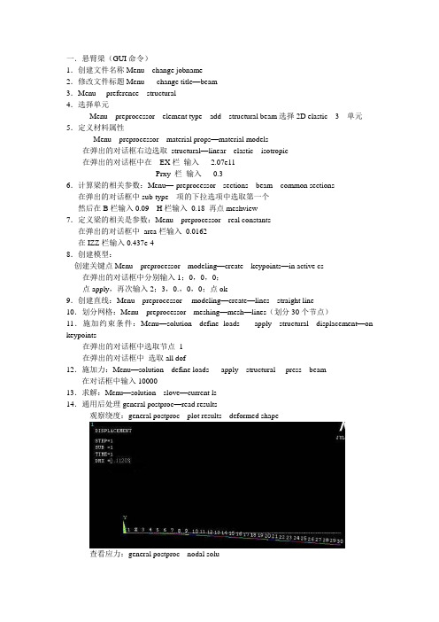
一.悬臂梁(GUI命令)1.创建文件名称Menu---change jobname----2.修改文件标题Menu ----change title—beam3.Menu----preference---structural4.选择单元Menu---preprocessor---element type---add---structural beam选择2D elastic 3 单元5.定义材料属性Menu---preprocessor---material props—material models在弹出的对话框右边选取structural—linear---elastic---isotropic在弹出的对话框中在EX栏输入 2.07e11Prxy 栏输入0.36.计算梁的相关参数:Menu—-preprocessor---sections---beam---common sections 在弹出的对话框中sub-type 项的下拉选项中选取第一个然后在B栏输入0.09 H栏输入0.18 再点meshview7.定义梁的相关是参数:Menu---preprocessor---real constants在弹出的对话框中area栏输入0.0162在IZZ栏输入0.437e-48.创建模型:创建关键点Menu---preprocessor---modeling—create---keypoints—in active cs 在弹出的对话框中分别输入1;0,0,0;点apply,再次输入2;3,0.,0,0;点ok9.创建直线:Menu---preprocessor--- modeling—create—lines---straight line10.划分网格:Menu---preprocessor---meshing—mesh—lines(划分30个节点)11.施加约束条件:Menu—solution---define loads---- apply---structural---displacement—on keypoints在弹出的对话框中选取节点 1在弹出的对话框中选取all dof12.施加力:Menu—solution---define loads---- apply---structural----press---beam--- 在对话框中输入1000013.求解:Menu—solution---slove—current ls14.通用后处理general postproc—read results观察绕度:general postproc---plot results---deformed shape查看应力:general postproc---nodal solu在弹出的对话框中选取stress—von mises stress二.薄壁长板(GUI命令)1.创建文件名称:执行Menu---change jobname----2.修改文件标题:执行Menu ----change title—zuoye33.选择单元:执行Menu---preprocessor---element type---add---structural solid选择Quad 4node 4.定义材料属性在real constants一栏中输入0.005,0.005,0.005,0.005执行Menu---preprocessor---material props—material models在弹出的对话框右边选取structural—linear---elastic---isotropic在弹出的对话框中在EX栏输入 2.1e11Prxy 栏输入0.27选取structural—Density 在弹出的对话框dens栏填入78405.创建模型:创建矩形:Menu---preprocessor--- modeling—create—areas ----rectangle—by dimensions 在弹出的对话框中输入0,1,0,1;7.划分网格:Menu---preprocessor---meshing—meshtool---在set area 在弹出的对话框中第一栏输入0.1 。
ANSYS Workbench 12.1官方中文培训教程
Workbench –Mechanical Introduction第一章简介B. ANSYS Workbench 简介Training Manual •什么是ANSYS Workbench?–ANSYS Workbench中提供了与ANSYS系统求解器的强大交互功能的方法。
这个环境提供了一个独特的CAD及设计过程的集成系统。
法这个环境提供了个独特的及设计过程的集成系统•ANSYS Workbench由多种的应用模块组成(例子):–Mechanical:利用ANSYS的求解器进行结构和热分析。
•网格划分也包含在Mechanical应用中。
–Mechanical APDL:采用传统的ANSYS用户界面对高级机械和多物理场进行分析。
–Fluid Flow (CFX):利用CFX进行CFD分析。
–Fluid Flow (FLUENT):使用FLUENT进行CFD分析。
Fl id Fl(FLUENT)–Geometry (DesignModeler):创建几何模型(DesignModeler)和CAD几何模型的修改。
Engineering Data:定义材料性能。
–Engineering Data–Meshing Application:用于生成CFD和显示动态网格。
–Design Exploration:优化分析。
()格行转–Finite Element Modeler (FE Modeler):对NASTRAN和ABAQUS的网格进行转化以进行ansys分析。
–BladeGen (Blade Geometry) :用于创建叶片几何模型。
–Explicit Dynamics:具有非线性动力学特色的模型用于显式动力学模拟。
Training Manual… ANSYS Workbench 简介•Workbench 环境支持两种类型的应用程序:–本地应用(workspaces):目前的本地应用包括工项目管理,工程数据和优化设计本机应用程序的启动完全在窗运行•本机应用程序的启动,完全在Workbench 窗口运行。
Ansys 12.0 CFX 官方教程 12
Translational motion:
– Train moving in a tunnel, longitudinal sloshing of fluid in a tank, etc.
General rigid-body motion
– Boat hulls, etc.
Boundary deformations
– Flap valves, flexible pipes, blood vessels, etc.
ANSYS, Inc. Proprietary 2009 ANSYS, Inc. All rights reserved.
Topics Domain Motion
– Rotating Fluid Domains
Single Frame of Reference Multiple Frames of Reference
– Frame Change Models – Pitch Change
Training Manual
Moving Zones
Overview of Moving Zones
Training Manual
Many engineering problems involve flows through domains which contain moving components Rotational motion:
x
Domain
Mesh Deformation – Domain changes shape as a function of time
Ansys_12.0_CFX_官方教程__10(Heat Transfer)

– Optically thick/dense means that the fluid absorbs and re-emits the radiation
• For optically thick media the P1 model is a good choice
– Many combustion simulations fall into this category since combustion gases tend to absorb radiation – The P1 models gives reasonable accuracy without too much computational effort
1) Rosseland Model (Diffusion Approximation Model) 2) P-1 Model (Gibb’s Model/Spherical Harmonics Model) 3) Discrete Transfer Model (DTM) (Shah Model) 4) Monte Carlo Model (not available in the ANSYS CFD-Flo product)
ANSYS, Inc. Proprietary © 2009 ANSYS, Inc. All rights
10-3
April 28, 2009 Inventory #002598
Heat Transfer
Governing Equations
Training Manual
• For multicomponent flows, reacting flows and radiation modeling additional terms are included in the energy equation
ANSYS12[1].0_及ANSYS12.0安装
![ANSYS12[1].0_及ANSYS12.0安装](https://img.taocdn.com/s3/m/9fab48a50029bd64783e2c85.png)
ANSYS12.0 及ANSYS12.0安装ANSYS 新版本在CAE 功能上引领现代产品研发科技,涉及的内容包括:高级分析、网格划分、优化、多物理场和多体动力学。
ANSYS Products的主体是ANSYS WORKBENCH,整合了Ansys诸多软件。
继续开发和提供世界一流的求解器技术提供了针对复杂仿真的多物理场耦合解决方法整合了ANSYS 的网格技术并产生统一的网格环境通过对先进的软硬件平台的支持来实现对大规模问题的高效求解继续改进最好的CAE 集成环境-ANSYS WORKBENCH继续融合先进的计算流体动力学技术加速多步求解ANSYS VT 加速器,基于ANSYS 变分技术,是通过减少迭代总步数以加速多步分析的数学方法。
这包括了收敛迭代和时间步迭代或者二者的综合。
收敛迭代的例子是非线性静态分析,不涉及接触或塑性,而时间步迭代指的是线性瞬态结构分析,二者组合的例子,非线性结构瞬态或者热瞬态分析。
网格变形和优化对于很多单位,进行优化分析的最大障碍是CAD 模型不能重新生成,特征参数不能反映那些修改研究的几何改变。
通过与ANSYS WORKBENCH 的结合,ANSYS MESH MORPHER(FE-MODELER 的新增加模块)可以实现这个功能,甚至更多。
通过网格操作而不是实体模型,ANSYS MESH MORPHER 对于来自于CAD 的非参数几何数据,如IGES 或者STEP,以及来自于ANSYS CDB 文件的网格数据,实现了模型参数化。
将网格读入FE MODELER,并且产生对应于该网格的“综合几何”的初次配置。
ANSYS MESH MORPHER 提供了四种不同的转换:面平移、面偏置、边平移和边偏置。
更多样的配置可以通过以上转换的组合实现。
例如,一个圆柱表面的面偏置就等效于变更其半径。
在ANSYS WORKBENCH 中,ANSYS 和ANSYS CFX 技术的集成取得了更大的进步。
ANSYS CFX 高性能计算配置指南
CFX并行任务提交
GUI提交: windows上:
CFX并行任务提交
CFX并行任务提交
GUI提交: Unix/Linux上:
直接进入…/ansys_inc/v120/cfx/bin下,运行./cfx5solve,界面同windows
CFX并行任务提交
命令行提交: Windows上:cfx5solve –def Benchmark.def -start-method "MPICH2 Local Parallel" part 4(单机并行) Unix/Linux上:cfx5solve -def Benchmark.def -start-method "MPICH2 Distributed Parallel" –par-dist cn01*4,cn02*4
MPI软件安装配置
Unix/Linux下: 对于以下平台,安装ansys的同时就装好了HP-MPI UNIX: hpux, hpux-ia64, osf Linux: linux, linux-amd64, linux-ia64
SGI下,各台机器上: /usr/lib/array/array.conf 中添加: array me machine localhost 例如:array default host1 host2 host3
END # SIMULATION CONTROL
MPI软件安装配置
Windows下(每个节点): 安装
<install_dir>\v121\CFX\bin\cfx5parallel -install-hpmpi-service <install_dir>\v121\CFX\bin\cfx5parallel -install-mpich2-service
Ansys_12.0_CFX_官方教程__17
– Ex. Create monitor points – Ex. Setup a multiconfiguration run
Training Manual
• Write .def file and start the solver
• Stage, Frozen Rotor, Transient Rotor Stator
– Solver parameters
• Advection Scheme • Time Scale/Step controls
ANSYS, Inc. Proprietary © 2009 ANSYS, Inc. All rights reserved.
B-11
April 28, 2009 Inventory #002598
Turbo Pre and Post
CFX-Pre General Mode
Training Manual
• After the case has been set up in Turbo Mode, the following modifications can be made in general mode: – Component mesh or case reload – One to One connections for periodic and stationary domain connections can be specified directly – Domain interface intersection control – Creation of monitor points and/or source points – Multi-configuration simulation – Execution control
Ansys 12.0 CFX 官方教程
ANSYS, Inc. Proprietary © 2009 ANSYS, Inc. All
April 28, 2009 Inventory #002598
Installation and Licensing
CFD Products
Training Manual
Appendix E Licensing
Introduction to CFX
ANSYS, Inc. Proprietary © 2009 ANSYS, Inc. All rights reserved.
E-1
April 28, 2009 Inventory #002598
Installation and Licensing
Installation and Licensing
CFD Products
Training Manual
• You may also have purchased the following modular products:
– Again, each product allows you to run only 1 task at a time
• “ANSYS CFD”
– Run ANSYS Meshing, CFX-Pre, CFX-Solver, CFD-Post or FLUENT
• “ANSYS CFX”
– Run ANSYS Meshing, CFX-Pre, CFX-Solver or CFD-Post
• “ANSYS FLUENT”
– Run ANSYS Meshing, FLUENT or CFD-Post
• “ANSYS CFD-Flo”
– A reduced capability version of CFX
Ansys12详细安装图解教程
Ansys安装教程这是在我32位Win7系统安装ansys12.0的教程;截图为32位程序,64位步骤基本一致,可作为参考。
ansys安装后会占用3G-6G内存,所以选择好位置,不推荐装在C盘,除了占空间大以外,另外的原因就是这是破解的,破解软件尽量避免装到C盘,否则做好重装系统的准备吧,这是有着血淋淋的教训啊!!!!注意:为了防止杀毒软件自动禁止某些进程,安装前最好关闭所有的杀毒软件,比如360、金山、卡巴斯基等,如果担心这样不安全,那就拔网线吧……win7安装ansys12的注意事项:前期准备:在Window7环境下安装ANSYS12,安装系统环境的时候,程序会出现错误提示“必须使用“控制面板”中的“打开或关闭Windows功能”安装或配置 Framewrok 2.0SP1”。
解决方法:只需要进入控制面板,在分类视图下,点击“程序”分类标题,在“打开或关闭windows功能”的列表中,勾选.NET Framework3.5项目下的两个复选框,确定即可。
(这一步最好在安装前就完成!)1安装准备工作!!!!下载好的ansys12.1。
现给出地址:(咱们大一班的可以直接过来拷)ansys12.064位迅雷下载地址:[高级有限元仿真].TLF-SOFT-ANSYS.PRODUCTS.V12.WIN64-MAGNiTUDE.iso(3.27GB)ansys12.032位迅雷下载地址:TLF-SOFT-ANSYS.PRODUCTS.V12.WIN32-MAGNiTUDE.iso(2.56GB)将iso文件解压到文件夹,需要注意的是,文件夹路径中不得出现中文。
(注意,这一点非常重要!!!!)2电脑准备电脑名必须为英文或数字,负责安装的用户(管理员身份)名必须为英文或数字,否则安装将失败。
3开始安装。
步骤1)先制作许可文件license,打开上图蓝色的文件夹,右击,以管理员身份运行,出来dos框,y,回车生成许可文件license,在其所在文件夹内。
ansys教程完整PDF.

SY SN A
果结验检�2 果结析分看查�1 理处后 .3 evlos 解求�2 项选步荷载及荷载义定�2 制控解求和项选析分义定�1 解求行进荷载加施 .2 件条荷载、件条束约加施�4 分划格网元限有�3 型模体实何几入读或建创�2 �性属料材、数常实、型类元单�义定性属元单�1 型模元限有建创——理处前 .1
法算�HPS�力动体流点质顺光● 析分合耦元限有、元界边�法方元界边MEB ● 析分场声时实● 析分动运体柔�体刚、动运体刚● 析分展扩纹裂�析分效失● 析分落跌�析分性容包片叶及撞鸟�真仿甲穿彻侵● 析分播传的波力应及果效爆起�拟模炸爆● 学声、体流、热、构结�析分合耦场理物多● 式模料材性线非种多001 ● 动启重、分划重格网、格网应适 ● 拉欧质物单、拉欧质物多● 析分�ELA�拉欧�日郎格拉意任● 型类触接种多十四�析分触接动自全● �ANYD-SL/SYSNA�析分力动态瞬性线非度高 .2
.系关次层的间之们它及以 ,元图型模体实类四 .3-3
SYSNA
e vitcejbO
stniopyeK
seniL
!sPOO
s e n iL
stniopyeK saerA
.除删能不元图阶低则�上元图阶高在连元图的阶低果如 :示提 �semuloV�体 • �saerA�面 • � s en iL � 线 • �stniopyeK�点键关 • �为系关次层的元图型模�阶高最到阶低最从
SYSNA
能功体总的口窗个六中IUG SYSNA .2-1
e vitcejbO
Ansys 12.0 CFX 官方教程 1
Gas Domain of interest Cyclone
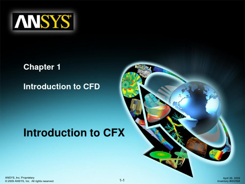
Can it be simplified or approximated as a 2D or axisymmetric problem?
L-valve Gas
Cyclone Separator
ANSYS, Inc. Proprietary 2009 ANSYS, Inc. All rights reserved.
– Remove unnecessary features that would complicate meshing (fillets, bolts…)? – Make use of symmetry or periodicity?
Do you need to split the model so that boundary conditions or domains can be created?
6. Define solver settings
Solve
7. Compute solution
7. Compute and monitor the solution
Post Processing
8. Examine results
ANSYS, Inc. Proprietary 2009 ANSYS, Inc. All rights reserved.
Problem Identification
1. 2. Define goals Identify domain
Training Manual
How will you isolate a piece of the complete physical system? Where will the computational domain begin and end?
ansys教程完整
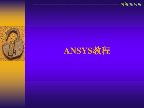
Total Force = 2pr = 47,124 lb.
坡度压力载荷沿起始关键点(I) 线性变化到第二个关键点 (J)。
1000 500 L3 VALI = 500 VALJ = 1000
如果加载后坡度的方向相反, 将 两个压力数值颠倒即可。
1000 500 L3 VALI = 1000 VALJ = 500
加载 (续)
加载轴对称载荷 轴对称载荷可加载到具有对称轴的3-D 结构上。 3-D 轴对称结构可用一2-D 轴对称模型描述。
Volumes Areas
OOPs!
Areas
Lines Keypoints
Lines Keypoints
2.布尔操作
要使用布尔操作: Main Menu: Preprocessor > -Modeling- Operate >
选择一种布尔操作 (例如: Add)
1. ..... 2. ..... 3. ..... Procedure
Areas
Keypoints
Lines
Area
Volume
ANSYS中图元(续)
层次关系
从最低阶到最高阶,模型图元的层次关系为: • 关键点(Keypoints) • 线(Lines) • 面(Areas) • 体(Volumes) 提示: 如果低阶的图元连在高阶图元上,则低阶图元不能删除.
I’ll just change this line
一、主要功能简介
1. 结构分析 1) 静力分析 - 用于静态载荷. 可以考虑结构的线性及 非线性行为。 ● 线性结构静力分析 ● 非线性结构静力分析 ♦ 几何非线性:大变形、大应变、应力强化、旋 转软化 ♦ 材料非线性:塑性、粘弹性、粘塑性、超弹性、 多线性弹性、蠕变、肿胀等 ♦ 接触非线性:面面 / 点面 / 点点接触、柔体 / 柔体 刚体接触、热接触 ♦ 单元非线性:死/活单元、钢筋混凝土单元、非 线性阻尼/弹簧元、预紧力单元等
ANSYSHELP说明
ANSYSHELP说明ANSYS的帮助文件使用说明很多网友都曾觉得ANSYS使用起来有一定的难度,经常会遇到这样或那样的问题,但市面上的参考书又不尽如人意,那究竟有没有比较好的参数书?有的,个人认为ANSYS的帮助文件就是一本不错的参数书。
接下来就ANSYS在线帮助的使用做一些基本的介绍,希望能对初学者有所帮助。
ANSYS的帮助文件包括所有ANSYS命令解释及所有的GUI解释,还包括ANSYS各模块的分析指南,实例练习等。
一.进入帮助系统可以通过下列三种方式进入:1.进入ANSYS的操作界面后,在应用菜单中选取Help进入;2.在ANSYS程序组中选取Help System进入:Start Menu > Programs > ANSYS XX>Help System;3.在任何对话框中选取Help。
二.帮助系统的内容安排:点击帮助系统的目录,就看到如下的ANSYS帮助系统的整体内容安排:1.前面4个部分是与软件版本,安装,注册相关的信息,只需作相应的了解即可,如下:※Release Notes※ANSYS Installation and Configuration Guide for UNIX※ANSYS Installation and Configuration Guide for Windows※ANSYS, Inc. Licensing Guide2.接下来两个部分是比较重要的部分,ANSYS的命令和单元手册,对用到的命令和单元应作详细的了解和掌握。
※ANSYS Commands Reference※ANSYS Element Reference3.下面四个部分是ANSYS相关的操作手册,说明如下:※Operations Guide 基本界面,操作指南※Basic Analysis Procedures Guide 基础分析指南※Advanced Analysis Techniques Guide 高级分析指南※Modeling and Meshing Guide 建模与分网指南4.以下几个部分则是ANSYS分模块的分析指南,如下:※Structural Analysis Guide 结构分析指南※Thermal Analysis Guide 热分析指南※CFD FLOTRAN Analysis Guide 流体分析指南※Electromagnetic Field Analysis Guide 电磁场分析指南※Coupled-Field Analysis Guide 耦合场分析指南5.为更好的使用ANSYS方便,快捷的解决更多的工程实际问题,建议仔细学习以下几个部分:※APDL Programmer's Guide:APDL操作手册※ANSYS Troubleshooting Guide:ANSYS错误信息指南※Mechanical Toolbar:机械工具栏※ANSYS/LS-DYNA User's Guide:ANSYS/LS-DYNA操作指南※ANSYS Connection Users Guide:接口技术指南6.欲快速掌握ANSYS的使用,莫过于通过实例和练习,而ANSYS的帮助系统中则提供大量的例题及练习供用户参考,所以以下两个部分是经常光顾的。
- 1、下载文档前请自行甄别文档内容的完整性,平台不提供额外的编辑、内容补充、找答案等附加服务。
- 2、"仅部分预览"的文档,不可在线预览部分如存在完整性等问题,可反馈申请退款(可完整预览的文档不适用该条件!)。
- 3、如文档侵犯您的权益,请联系客服反馈,我们会尽快为您处理(人工客服工作时间:9:00-18:30)。
– Solver parameters
• Advection Scheme • Time Scale/Step controls
ANSYS, Inc. Proprietary © 2009 ANSYS, Inc. All rights reserved.
B-13
April 28, 2009 Inventory #002598
Turbo Pre and Post
CFD-Post Turbo Workspace
Training Manual
• The Turbo workspace improves and speeds up postprocessing for turbo machinery simulations
ANSYS, Inc. Proprietary © 2009 ANSYS, Inc. All rights reserved.
B-12
April 28, 2009 Inventory #002598
Turbo Post
ANSYS, Inc. Proprietary © 2009 ANSYS, Inc. All rights reserved.
ANSYS, Inc. Proprietary © 2009 ANSYS, Inc. All rights reserved.
B-2
April 28, 2009 Inventory #002598
Turbo Pre and Post
CFX-Pre Turbo Mode
Training Manual
• • • • • Frozen rotor Transient rotor stator Stage Periodic None
Training Manual
– Right-click to add or delete interfaces
ANSYS, Inc. Proprietary © 2009 ANSYS, Inc. All rights reserved.
B-8
April 28, 2009 Inventory #002598
Turbo Pre and Post
CFX-Pre Turbo Mode 5. Boundary Definition – Boundary regions and conditions automatically setup! – Define/check boundary conditions – Right-click to add or remove boundary conditions
• At any time, users can enter turbo mode from the file menu – Tools > Turbo Mode • Buttons at bottom to navigate through the wizard: – Next – move to the next page – Back – move to the previous page – Finish – any data that has been entered will be committed, Pre goes into General Mode – Cancel – close Turbo mode and revert to General Mode
ANSYS, Inc. Proprietary © 2009 ANSYS, Inc. All rights reserved.
B-6
April 28, 2009 Inventory #002598
Turbo Pre and Post
CFX-Pre Turbo Mode 3. Physics Definition – Fluid properties – Steady State vs. Transient – Model Data
Training Manual
ANSYS, Inc. Proprietary © 2009 ANSYS, Inc. All rights reserved.
B-9
April 28, 2009 Inventory #002598
Turbo Pre and Post
CFX-Pre Turbo Mode 6. Final Operations – Options:
– Option to quit CFX Pre
ANSYS, Inc. Proprietary © 2009 ANSYS, Inc. All rights reserved.
B-10
April 28, 2009 Inventory #002598
Turbo Pre and Post
CFX-Pre Turbo Mode •
B-11
April 28, 2009 Inventory #002598
Turbo Pre and Post
CFX-ining Manual
• After the case has been set up in Turbo Mode, the following modifications can be made in general mode: – Component mesh or case reload – One to One connections for periodic and stationary domain connections can be specified directly – Domain interface intersection control – Creation of monitor points and/or source points – Multi-configuration simulation – Execution control
• Energy and Turbulence Models
Training Manual
– Boundary Templates:
• Pt inlet - Ps outlet • Pt inlet - mass flow outlet • Mass flow inlet – Ps outlet
– Interface Type:
CFX-Pre Turbo Mode 1. Basic Settings – setup axis of rotation and coordinate frame
Training Manual
ANSYS, Inc. Proprietary © 2009 ANSYS, Inc. All rights reserved.
1. 2. 3. 4. 5. 6.
Training Manual
Summary – six steps to setup a turbomachinery simulation:
Basic Settings Component Definition Physics Definition Interface Definition Boundary Definition Final Operation
Appendix B Turbo Pre and Post
Introduction to CFX
ANSYS, Inc. Proprietary © 2009 ANSYS, Inc. All rights reserved.
B-1
April 28, 2009 Inventory #002598
Turbo Pre
All Turbo postprocessing performed on the Turbo tab
ANSYS, Inc. Proprietary © 2009 ANSYS, Inc. All rights reserved.
B-14
April 28, 2009 Inventory #002598
ANSYS, Inc. Proprietary © 2009 ANSYS, Inc. All rights reserved.
B-3
April 28, 2009 Inventory #002598
Turbo Pre and Post
CFX-Pre Turbo Mode
Training Manual
•
– –
Advantages:
Rapid setup for turbomachinery simulations Automatic creation of domain interfaces and boundary definitions
ANSYS, Inc. Proprietary © 2009 ANSYS, Inc. All rights reserved.
• Turbo mode in ANSYS CFX-Pre is a specialist mode allowing users to set up turbo machinery simulations, such as compressors or turbines, in a simple manner.
B-7
April 28, 2009 Inventory #002598
Turbo Pre and Post
CFX-Pre Turbo Mode 4. Interface Definition – Domain interfaces automatically generated! – Setup/check all Domain Interfaces
B-5
April 28, 2009 Inventory #002598
Turbo Pre and Post
CFX-Pre Turbo Mode 2. Component Definition – Import meshes (right-click) – Define rotating or stationary
